Embed Size (px)
Citation preview
A Course Material on
Medical Electronics
By
Ms.P.VEENA
ASSISTANT PROFESSOR
DEPARTMENT OF ELECTRONICS AND COMMUNICATIONENGINEERING
SASURIE COLLEGE OF ENGINEERING
VIJAYAMANGALAM – 638 056
www.Vidyarthiplus.com
www.Vidyarthiplus.com
QUALITY CERTIFICATE
This is to certify that the e-course material
Subject Code : EC2021
Scubject : Medical Electronics
Class : III Year ECE
being prepared by me and it meets the knowledge requirement of the universitycurriculum.
Signature of the Author
P.Veena
Assistant Professor
This is to certify that the course material being prepared Ms.P.Veena is of adequatequality. She has referred more than five books among them minimum one is fromabroad author.
Signature of HD
N.RAMKUMAR
ASSISTANT PROFESSOR
www.Vidyarthiplus.com
www.Vidyarthiplus.com
TABLE OF CONTENTS
S.NO TOPICPAGE NO
UNIT I
ELECTRO-PHYSIOLOGY AND BIO-POTENTIAL RECORDING
1.1ORIGIN OF BIOPOTENTIALS
1
1.2BIO POTENTIAL ELCTRODES
4
1.3BIOLOGICAL AMPLIFIERS
10
1.4ELECTROCARDIOGRAPHY(ECG)
111.5
ELECTROENCEPHALOGRAPHY(EEG)18
1.6ELECTROMYOGRAPHY(EMG)
26
1.7ELECTROCULOGRAM(EOG)
29
1.8PHONOCARDIOGRAM(PCG)
31
UNIT II
BIO-CHEMICAL AND NON ELECTRICAL PARAMETER MEASUREMENT
2.1PH
342.2
PO2 352.3
PCO236
2.4PHCO3
36
2.5ELCTROPHORESIS
38
2.6COLORIMETER
402.7
PHOTOMETER41
2.8AUTOANALYZER
43
2.9BLOOD FLOW METER
43
2.10CARDIAC OUTPUT
50
2.11RESPIRATORY MEASUREMENT
522.12
BLOOD PRESSURE57
2.13 TEMPERATURE 652.14
PULSE MEASUREMENT66
www.Vidyarthiplus.com
www.Vidyarthiplus.com
2.15BLOOD CELL COUNTERS
68UNIT III
ASSIST DEVICES AND BIO-TELEMETRY
3.1CARDIAC PACEMAKERS
713.2
DC DEFIBRILLATOR75
3.3TELEMETRY PRINCIPLES & BIO TELEMETRY
80
3.4RADIO PILL AND TELESTIMULASTION
88
UNIT IV
RADIOLOGICAL EQUIPMENTS
4.1IONISING RADIATION
894.2
DIAGNOSTIC EQUIPMENT93
4.3USE OF RADIO ISOTOPE IN DIAGNOSIS
99
4.4RADIATION THERAPY
101
UNIT V
RECENT TRENDS IN MEDICAL INSTRUMENTATION
5.1THERMOGRAPH
1065.2
ENDOSCOPY UNIT109
5.3LASER IN MEDICINE
117
5.4DIATHERMY UNITS
1245.5
ELECTRICAL SAFETY IN MEDICAL EQUIPMENT129
APPENDICESA GLOSSARYB QUESTION BANKC UNIVERSITY QUESTIONS
www.Vidyarthiplus.com
www.Vidyarthiplus.com
EC2021 MEDICAL ELECTRONICS L T P 3 0 0 3
AIMTo make students to understand the applications of electronics in diagnostic andtherapeutic area.
OBJECTIVES To study the methods of recording various biopotentials To study how to measure biochemical and various physiological information To understand the working of units which will help to restore normal functioning To understand the use of radiation for diagnostic and therapy To understand the need and technique of electrical safety in Hospitals
UNIT I ELECTRO-PHYSIOLOGY AND BIO-POTENTIALRECORDING 9The origin of Bio-potentials; biopotential electrodes, biological amplifiers, ECG,EEG, EMG, PCG, EOG, lead systems and recording methods, typical waveforms andsignal characteristics.
UNIT II BIO-CHEMICAL AND NON ELECTRICAL PARAMETERMEASUREMENT 9
PH, PO2, PCO2, PHCO3, Electrophoresis, colorimeter, photometer, Auto analyzer,Blood flow meter, cardiac output, respiratory measurement, Blood
pressure, temperature, pulse, and Blood cell counters.
UNIT III ASSIST DEVICES AND BIO-TELEMETRY 9Cardiac pacemakers, DC Defibrillator, Telemetry principles, frequency selection, Bio-telemetry, radio-pill and tele-stimulation.
UNIT IV RADIOLOGICAL EQUIPMENTS 9Ionizing radiation, Diagnostic x-ray equipments, use of Radio Isotope indiagnosis, Radiation Therapy.
UNIT V RECENT TRENDS IN MEDICAL INSTRUMENTATION 9Thermograph, endoscopy unit, Laser in medicine, Diathermy units, Electrical safety inmedical equipment.
TEXT BOOK1. Leislie Cromwell, “Biomedical instrumentation and measurement”, PrenticeHall of India, New Delhi, 2007.
REFERENCES TOTAL PERIOS:451. Khandpur, R.S., “Handbook of Biomedical Instrumentation”, TATA McGraw-Hill,New Delhi, 2003.2. Joseph J.Carr and John M.Brown, “Introduction to Biomedical
equipmentTechnology”, John Wiley and Sons, New York, 2004.
www.Vidyarthiplus.com
www.Vidyarthiplus.com

www.Vidyarthiplus.com
www.Vidyarthiplus.com

www.Vidyarthiplus.com
www.Vidyarthiplus.com
EC2021 MEDICAL ELECTRONICS
SCE 1 DEPT.OF ECE
UNIT I
ELECTRO-PHYSIOLOGY AND BIO-POTENTIAL RECORDING
1.1 THE ORIGIN OF BIO-POTENTIALS:
Bioelectric phenomenon is of immense importance to biomedical engineers becausethese potentials are routinely recorded in modern clinical practice.
ECG (Electrocardiogram), EMG (Electromyogram), EEG (Electroencephalogram), ENG(Electroneurogram), EOG (Electro-oculogram), ERG (Electroretinogram), etc. are someexamples of biopotentials. We will briefly look at origin of ENG, EMG and ECG in thistalk.
As engineers, we should have a good physical insight into the nature of electromagneticfields generated by bioelectric sources. Therefore we could contribute to quantitativesolution of biological problems.
To understand the origin of biopotentials we need to focus on:
Bioelectric phenomena at the cellular level Volume conductor fields of simple bioelectric sources Volume conductor fields of complex bioelectric sources Volume conductor fields as a necessary link between cellular activity and gross externally
recorded biological signals
1.1.1 ELECTRICAL ACTIVITY OF EXCITABLE CELLS
Biopotentials are produced as a result of electrochemical activity of excitable cells: i.e.,nervous, muscular (cardiac and smooth) and glandular cells
Factors influencing the flow of ions across the cell membrane
Diffusion gradients Inwardly directed electric field (inside negative, outside positive) Membrane structure (availability of pores; K+, Na+and permeability of membrane to
different ions) Active transport of ions across membrane against established electrochemical gradients When appropriately stimulated, they generate an action potential (flow of ions across the
cell membrane and generation of a propagating wave of depolarization along themembrane)
www.Vidyarthiplus.com
www.Vidyarthiplus.com
EC2021 MEDICAL ELECTRONICS
SCE 2 DEPT.OF ECE
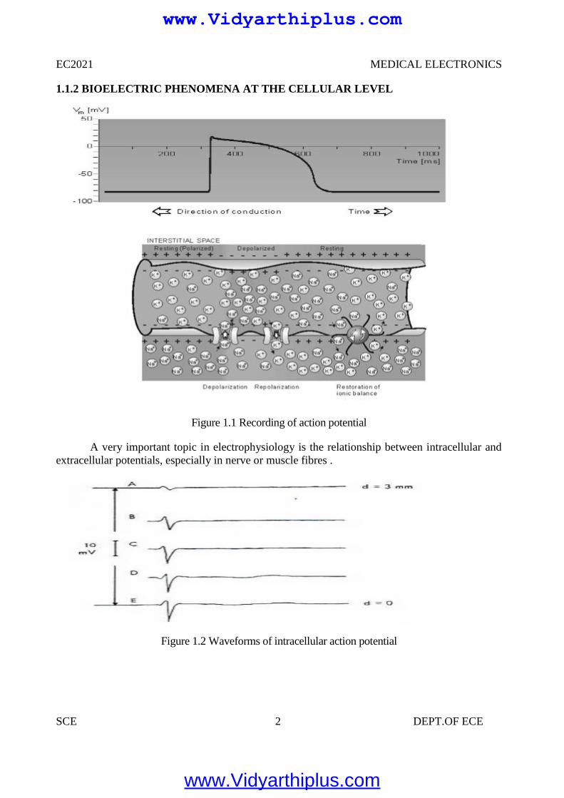
1.1.2 BIOELECTRIC PHENOMENA AT THE CELLULAR LEVEL
Figure 1.1 Recording of action potential
A very important topic in electrophysiology is the relationship between intracellular andextracellular potentials, especially in nerve or muscle fibres .
Figure 1.2 Waveforms of intracellular action potential
EC2021 MEDICAL ELECTRONICS
SCE 2 DEPT.OF ECE
1.1.2 BIOELECTRIC PHENOMENA AT THE CELLULAR LEVEL
Figure 1.1 Recording of action potential
A very important topic in electrophysiology is the relationship between intracellular andextracellular potentials, especially in nerve or muscle fibres .
Figure 1.2 Waveforms of intracellular action potential
www.Vidyarthiplus.com
www.Vidyarthiplus.com
EC2021 MEDICAL ELECTRONICS
SCE 3 DEPT.OF ECE
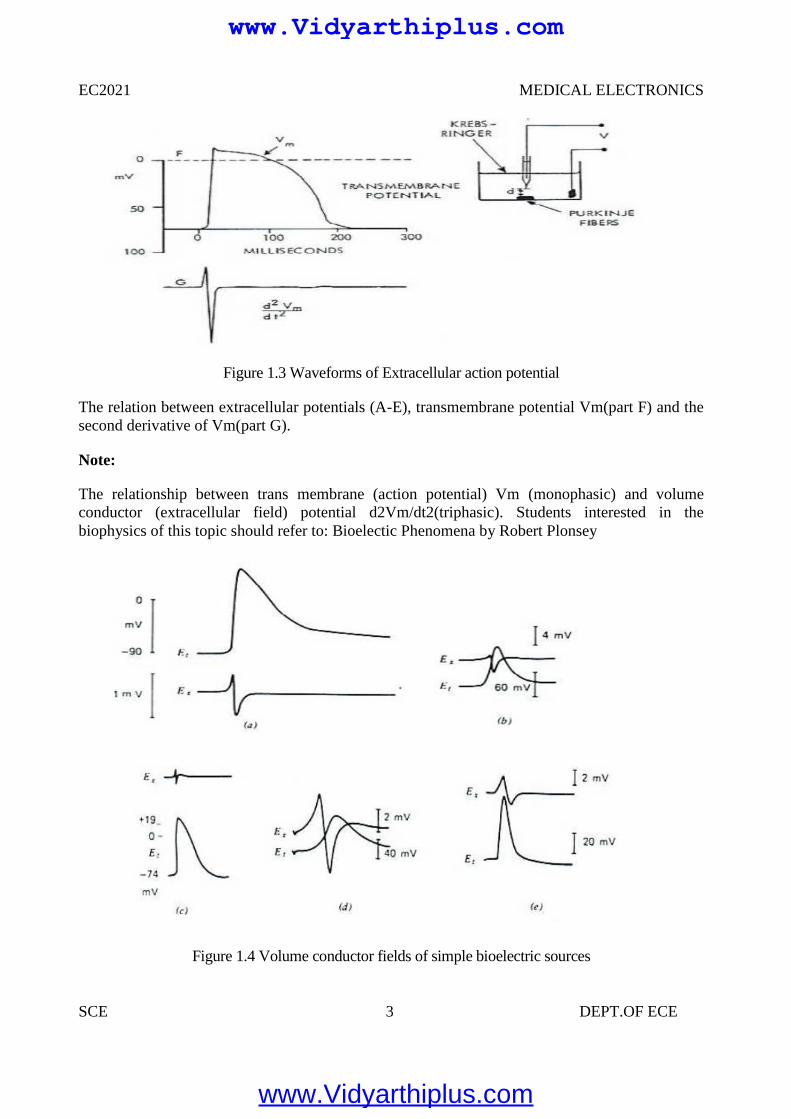
Figure 1.3 Waveforms of Extracellular action potential
The relation between extracellular potentials (A-E), transmembrane potential Vm(part F) and thesecond derivative of Vm(part G).
Note:
The relationship between trans membrane (action potential) Vm (monophasic) and volumeconductor (extracellular field) potential d2Vm/dt2(triphasic). Students interested in thebiophysics of this topic should refer to: Bioelectic Phenomena by Robert Plonsey
Figure 1.4 Volume conductor fields of simple bioelectric sources
www.Vidyarthiplus.com
www.Vidyarthiplus.com
EC2021 MEDICAL ELECTRONICS
SCE 4 DEPT.OF ECE
Trans membrane (Et= Vm) and extracellular action potentials (Ex) obtained from differentexcitable tissues. Note the monophasic and triphasic shapes.
a. Frog semitendinous muscleb. Toad sartorius musclec. Rabbit atriumd .Squid giant axon.
1.2 BIOPOTENTIAL ELECTRODES
Electrode – Electrolyte Interface
General Ionic Equations
C<->Cn+ +ne-
Am-<->A +me -
If electrode has same material as cation, then this material gets oxidized and enters theelectrolyte as a cation and electrons remain at the electrode and flow in the externalcircuit.
If anion can be oxidized at the electrode to form a neutral atom, one or two electrons aregiven to the electrode
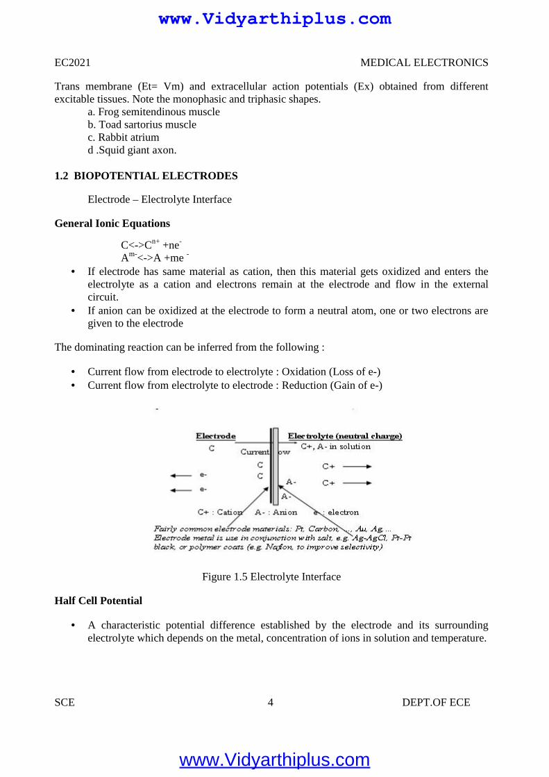
The dominating reaction can be inferred from the following :
Current flow from electrode to electrolyte : Oxidation (Loss of e-) Current flow from electrolyte to electrode : Reduction (Gain of e-)
Figure 1.5 Electrolyte Interface
Half Cell Potential
A characteristic potential difference established by the electrode and its surroundingelectrolyte which depends on the metal, concentration of ions in solution and temperature.
EC2021 MEDICAL ELECTRONICS
SCE 4 DEPT.OF ECE
Trans membrane (Et= Vm) and extracellular action potentials (Ex) obtained from differentexcitable tissues. Note the monophasic and triphasic shapes.
a. Frog semitendinous muscleb. Toad sartorius musclec. Rabbit atriumd .Squid giant axon.
1.2 BIOPOTENTIAL ELECTRODES
Electrode – Electrolyte Interface
General Ionic Equations
C<->Cn+ +ne-
Am-<->A +me -
If electrode has same material as cation, then this material gets oxidized and enters theelectrolyte as a cation and electrons remain at the electrode and flow in the externalcircuit.
If anion can be oxidized at the electrode to form a neutral atom, one or two electrons aregiven to the electrode
The dominating reaction can be inferred from the following :
Current flow from electrode to electrolyte : Oxidation (Loss of e-) Current flow from electrolyte to electrode : Reduction (Gain of e-)
Figure 1.5 Electrolyte Interface
Half Cell Potential
A characteristic potential difference established by the electrode and its surroundingelectrolyte which depends on the metal, concentration of ions in solution and temperature.
www.Vidyarthiplus.com
www.Vidyarthiplus.com
EC2021 MEDICAL ELECTRONICS
SCE 5 DEPT.OF ECE
Half cell potential cannot be measured without a second electrode.
The half cell potential of the standard hydrogen electrode has been arbitrarily set to zero.Other half cell potentials are expressed as a potential difference with this electrode.
Reason for Half Cell Potential : Charge Separation at Interface
Oxidation or reduction reactions at the electrode-electrolyte interface lead to a double-charge layer, similar to that which exists along electrically active biological cellmembranes.
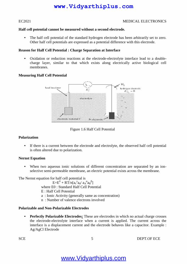
Measuring Half Cell Potential
Figure 1.6 Half Cell Potential
Polarization
If there is a current between the electrode and electrolyte, the observed half cell potentialis often altered due to polarization.
Nernst Equation
When two aqueous ionic solutions of different concentration are separated by an ion-selective semi-permeable membrane, an electric potential exists across the membrane.
The Nernst equation for half cell potential isE=E0 + RT/n[ac
yad/ aAαaB
β]where E0 : Standard Half Cell PotentialE : Half Cell Potentiala : Ionic Activity (generally same as concentration)n : Number of valence electrons involved
Polarizable and Non-Polarizable Electrodes
Perfectly Polarizable Electrodes: These are electrodes in which no actual charge crossesthe electrode-electrolyte interface when a current is applied. The current across theinterface is a displacement current and the electrode behaves like a capacitor. Example :Ag/AgCl Electrode
EC2021 MEDICAL ELECTRONICS
SCE 5 DEPT.OF ECE
Half cell potential cannot be measured without a second electrode.
The half cell potential of the standard hydrogen electrode has been arbitrarily set to zero.Other half cell potentials are expressed as a potential difference with this electrode.
Reason for Half Cell Potential : Charge Separation at Interface
Oxidation or reduction reactions at the electrode-electrolyte interface lead to a double-charge layer, similar to that which exists along electrically active biological cellmembranes.
Measuring Half Cell Potential
Figure 1.6 Half Cell Potential
Polarization
If there is a current between the electrode and electrolyte, the observed half cell potentialis often altered due to polarization.
Nernst Equation
When two aqueous ionic solutions of different concentration are separated by an ion-selective semi-permeable membrane, an electric potential exists across the membrane.
The Nernst equation for half cell potential isE=E0 + RT/n[ac
yad/ aAαaB
β]where E0 : Standard Half Cell PotentialE : Half Cell Potentiala : Ionic Activity (generally same as concentration)n : Number of valence electrons involved
Polarizable and Non-Polarizable Electrodes
Perfectly Polarizable Electrodes: These are electrodes in which no actual charge crossesthe electrode-electrolyte interface when a current is applied. The current across theinterface is a displacement current and the electrode behaves like a capacitor. Example :Ag/AgCl Electrode
www.Vidyarthiplus.com
www.Vidyarthiplus.com
EC2021 MEDICAL ELECTRONICS
SCE 6 DEPT.OF ECE
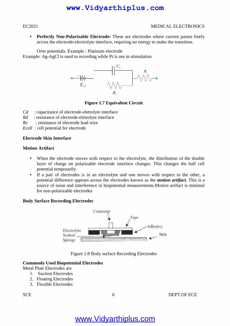
Perfectly Non-Polarizable Electrode: These are electrodes where current passes freelyacross the electrode-electrolyte interface, requiring no energy to make the transition.
Over potentials. Example : Platinum electrodeExample: Ag-AgCl is used in recording while Pt is use in stimulation
Figure 1.7 Equivalent Circuit
Cd : capacitance of electrode-eletrolyte interfaceRd : resistance of electrode-eletrolyte interfaceRs : resistance of electrode lead wireEcell : cell potential for electrode
Electrode Skin Interface
Motion Artifact
When the electrode moves with respect to the electrolyte, the distribution of the doublelayer of charge on polarizable electrode interface changes. This changes the half cellpotential temporarily.
If a pair of electrodes is in an electrolyte and one moves with respect to the other, apotential difference appears across the electrodes known as the motion artifact. This is asource of noise and interference in biopotential measurements.Motion artifact is minimalfor non-polarizable electrodes
Body Surface Recording Electrodes
Figure 1.8 Body surface Recording Electrodes
Commonly Used Biopotential ElectrodesMetal Plate Electrodes are
1. Suction Electrodes2. Floating Electrodes3. Flexible Electrodes
www.Vidyarthiplus.com
www.Vidyarthiplus.com
EC2021 MEDICAL ELECTRONICS
SCE 7 DEPT.OF ECE
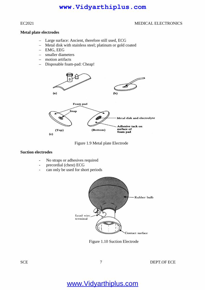
Metal plate electrodes
– Large surface: Ancient, therefore still used, ECG– Metal disk with stainless steel; platinum or gold coated– EMG, EEG– smaller diameters– motion artifacts– Disposable foam-pad: Cheap!
Figure 1.9 Metal plate Electrode
Suction electrodes
- No straps or adhesives required- precordial (chest) ECG- can only be used for short periods
Figure 1.10 Suction Electrode
www.Vidyarthiplus.com
www.Vidyarthiplus.com
EC2021 MEDICAL ELECTRONICS
SCE 8 DEPT.OF ECE
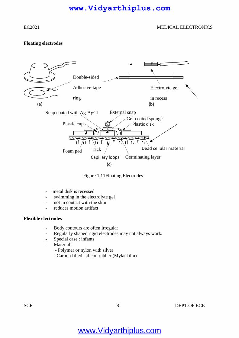
Floating electrodes
- metal disk is recessed- swimming in the electrolyte gel- not in contact with the skin- reduces motion artifact
Flexible electrodes
- Body contours are often irregular- Regularly shaped rigid electrodes may not always work.- Special case : infants- Material :
- Polymer or nylon with silver- Carbon filled silicon rubber (Mylar film)
Double-sided
Adhesive-tape
ring
Electrolyte gel
in recess(a) (b)
(c)
Snap coated with Ag-AgCl External snap
Plastic cup
Tack
Plastic disk
Foam padCapillary loops
Dead cellular material
Germinating layer
Gel-coated sponge
Figure 1.11Floating Electrodes
www.Vidyarthiplus.com
www.Vidyarthiplus.com
EC2021 MEDICAL ELECTRONICS
SCE 9 DEPT.OF ECE
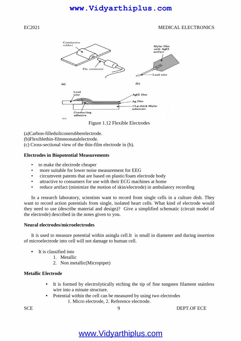
Figure 1.12 Flexible Electrodes
(a)Carbon-filledsiliconerubberelectrode.(b)Flexiblethin-filmneonatalelectrode.(c) Cross-sectional view of the thin-film electrode in (b).
Electrodes in Biopotential Measurements
• to make the electrode cheaper• more suitable for lower noise measurement for EEG• circumvent patents that are based on plastic/foam electrode body• attractive to consumers for use with their ECG machines at home• reduce artifact (minimize the motion of skin/electrode) in ambulatory recording
In a research laboratory, scientists want to record from single cells in a culture dish. Theywant to record action potentials from single, isolated heart cells. What kind of electrode wouldthey need to use (describe material and design)? Give a simplified schematic (circuit model ofthe electrode) described in the notes given to you.
Neural electrodes/microelectrodes
It is used to measure potential within asingla cell.It is small in diameter and during insertionof microelectrode into cell will not damage to human cell.
It is classified into1. Metallic2. Non metallic(Micropipet)
Metallic Electrode
It is formed by electrolytically etching the tip of fine tungsten filament stainlesswire into a minute structure.
Potential within the cell can be measured by using two electrodes1. Micro electrode, 2. Reference electrode.
www.Vidyarthiplus.com
www.Vidyarthiplus.com
EC2021 MEDICAL ELECTRONICS
SCE 10 DEPT.OF ECE
Non Metallic (Micropipet)
It is used to measure the potential within the single cell using non metallicmaterial is used.
It is filled within an electrolyte ,that is compatible with the cellular fluids.
1.3 BIOPOTENTIAL AMPLIFIERS
These are very important part of modern medical instrumentation. We need toamplify biopotentials which are generated in the body at low levels with highsource impedance.
Biopotentials amplifiers are required to increase signal strength while maintainingfidelity
Basic Requirements of Biopotential Amplifiers
Essential functions of a bioamplifier are:
• To take a weak biopotential and increase its amplitude so that it can be processed,recorded or displayed• To amplify voltage, but it could be considered as a power amplifier as well.To amplify
current since in some cases a biopotential amplifier is used to isolate the load from the sourcecurrent gain only
Input Impedance (Zin)
• All biopotential amplifiers must have high input impedance minimize loading(remember the characteristics of biopotential electrodes resulting into loading and distortion ifinput impedance of the amplifier is not high enough) – typical values of Zin over the frequencyrange of the measure and = 10 MΩ (remember the loading rule)
Protection & Isolation
• The input circuit of a biopotential amplifier must provide protection to the live measureVbio
• Any potential or current at amplifier’s input terminals can affectVbio
• Electric currents produced by the biopotential amplifier can result in microshock andmacro shock• The bioamplifier must have isolation and protection circuitry so that the current throughthe electrodes can be kept at safe levels and any artifact generated by such current can beminimized
Output Impedance (Zout)
The output circuit does not present any critical problems, all it needs to do is to drive theload
Output impedance must be low with respect to the load impedance and it must be capableof satisfying the power requirements of the load
www.Vidyarthiplus.com
www.Vidyarthiplus.com
EC2021 MEDICAL ELECTRONICS
SCE 11 DEPT.OF ECE
Bandwidth (BW)
Frequency response
• The biopotential amplifier must be sensitive to important frequency components of thebiosignal• Since biopotentials are low level signals, it is important to limit bandwidth optimizesignal-to-noise ratio
Gain (G)
• Biopotential amplifiers have a gain of 1000 or greater
Mode of Operation
• Very frequently biosignals are obtained from bipolar electrodes• Electrodes symmetrically located with respect to ground need differential amplification• High CMRR required because:
1. Common mode signals much greater than the biosignal appear on bipolar electrodes2. Symmetry with respect to ground is not perfect (mismatch between electrode impedances) –more on this later
Calibration Signal
Medical and clinical equipment require quick calibration. The gain of the biopotentialamplifier must be calibrated to provide us with an accurate indication of the signal’samplitude
Push button to apply standard signal to the input of the biopotential amplifier Adjustable gain switch carefully selects calibrated fixed gains.
1.4 ELECTROCARDIOGRAPHY (ECG)
A very widely used medical instrument, which is utilized to diagnose and monitor cardiacbeat abnormalities, is the electrocardiograph.
It measures the electrical activity of the heart (more precisely biopotential differencesarising from the electrical activity of myocardium). We’ve already talked about thegenesis of the ECG signal.
The ECG machine uses surface electrodes and high input impedance Differential amplifiers with good common mode rejection ratio to record the
electrocardiogram Normal ECG amplitude ranges between 0.5-4 mV. Normal frequency content of ECG
(for diagnostic purposes) is 0.05-100 Hz. A typical ECG waveform is shown below:
www.Vidyarthiplus.com
www.Vidyarthiplus.com
EC2021 MEDICAL ELECTRONICS
SCE 12 DEPT.OF ECE
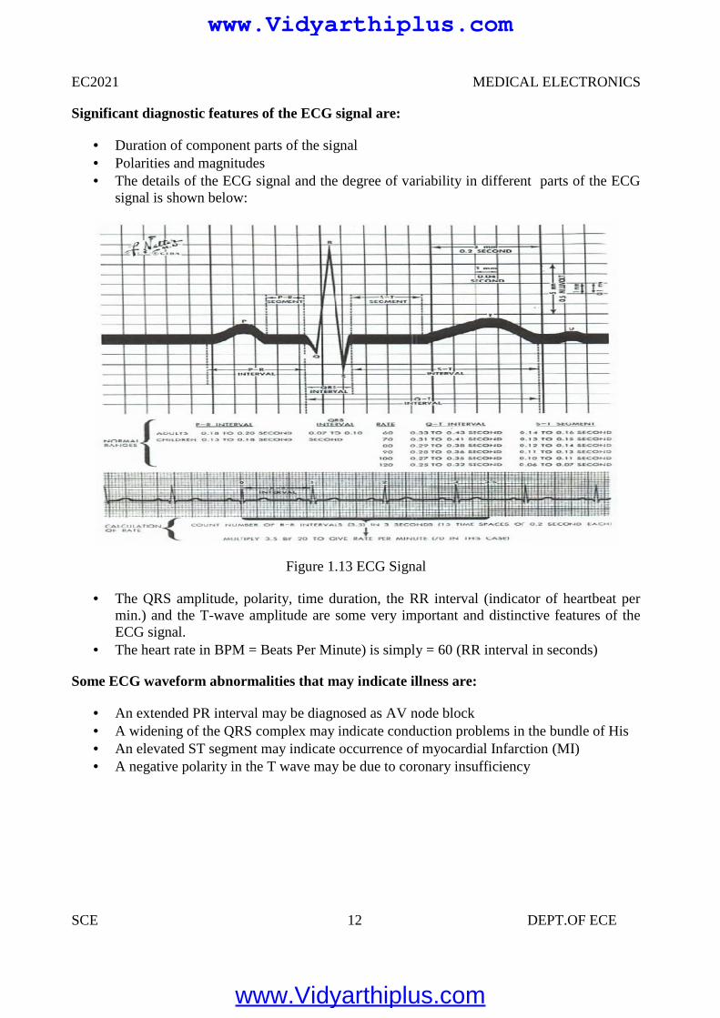
Significant diagnostic features of the ECG signal are:
Duration of component parts of the signal Polarities and magnitudes The details of the ECG signal and the degree of variability in different parts of the ECG
signal is shown below:
Figure 1.13 ECG Signal
The QRS amplitude, polarity, time duration, the RR interval (indicator of heartbeat permin.) and the T-wave amplitude are some very important and distinctive features of theECG signal.
The heart rate in BPM = Beats Per Minute) is simply = 60 (RR interval in seconds)
Some ECG waveform abnormalities that may indicate illness are:
An extended PR interval may be diagnosed as AV node block A widening of the QRS complex may indicate conduction problems in the bundle of His An elevated ST segment may indicate occurrence of myocardial Infarction (MI) A negative polarity in the T wave may be due to coronary insufficiency
www.Vidyarthiplus.com
www.Vidyarthiplus.com
EC2021 MEDICAL ELECTRONICS
SCE 13 DEPT.OF ECE
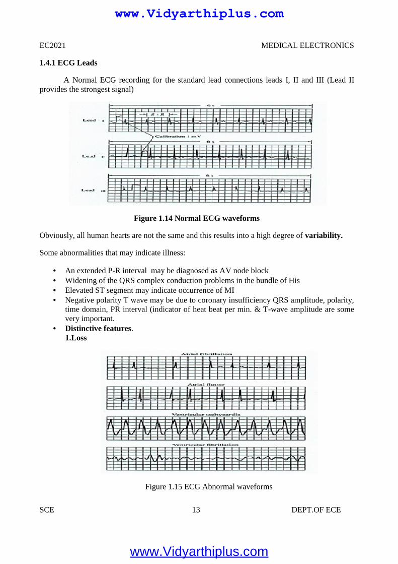
1.4.1 ECG Leads
A Normal ECG recording for the standard lead connections leads I, II and III (Lead IIprovides the strongest signal)
Figure 1.14 Normal ECG waveforms
Obviously, all human hearts are not the same and this results into a high degree of variability.
Some abnormalities that may indicate illness:
An extended P-R interval may be diagnosed as AV node block Widening of the QRS complex conduction problems in the bundle of His Elevated ST segment may indicate occurrence of MI Negative polarity T wave may be due to coronary insufficiency QRS amplitude, polarity,
time domain, PR interval (indicator of heat beat per min. & T-wave amplitude are somevery important.
Distinctive features.1.Loss
Figure 1.15 ECG Abnormal waveforms
www.Vidyarthiplus.com
www.Vidyarthiplus.com
EC2021 MEDICAL ELECTRONICS
SCE 14 DEPT.OF ECE
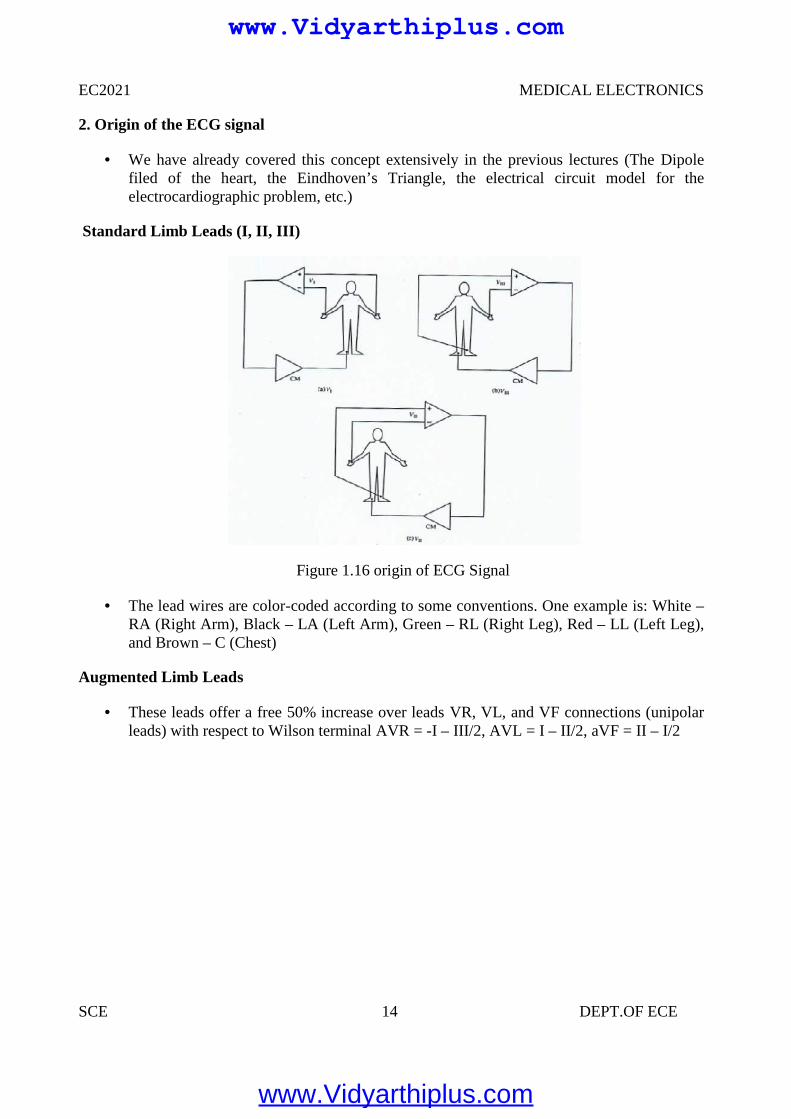
2. Origin of the ECG signal
We have already covered this concept extensively in the previous lectures (The Dipolefiled of the heart, the Eindhoven’s Triangle, the electrical circuit model for theelectrocardiographic problem, etc.)
Standard Limb Leads (I, II, III)
Figure 1.16 origin of ECG Signal
The lead wires are color-coded according to some conventions. One example is: White –RA (Right Arm), Black – LA (Left Arm), Green – RL (Right Leg), Red – LL (Left Leg),and Brown – C (Chest)
Augmented Limb Leads
These leads offer a free 50% increase over leads VR, VL, and VF connections (unipolarleads) with respect to Wilson terminal AVR = -I – III/2, AVL = I – II/2, aVF = II – I/2
www.Vidyarthiplus.com
www.Vidyarthiplus.com
EC2021 MEDICAL ELECTRONICS
SCE 15 DEPT.OF ECE
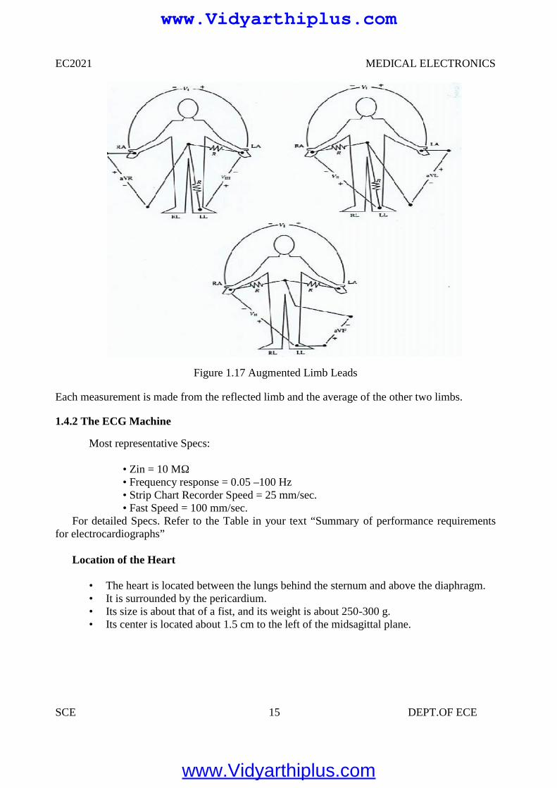
Figure 1.17 Augmented Limb Leads
Each measurement is made from the reflected limb and the average of the other two limbs.
1.4.2 The ECG Machine
Most representative Specs:
• Zin = 10 MΩ• Frequency response = 0.05 –100 Hz• Strip Chart Recorder Speed = 25 mm/sec.• Fast Speed = 100 mm/sec.
For detailed Specs. Refer to the Table in your text “Summary of performance requirementsfor electrocardiographs”
Location of the Heart
• The heart is located between the lungs behind the sternum and above the diaphragm.• It is surrounded by the pericardium.• Its size is about that of a fist, and its weight is about 250-300 g.• Its center is located about 1.5 cm to the left of the midsagittal plane.
www.Vidyarthiplus.com
www.Vidyarthiplus.com
EC2021 MEDICAL ELECTRONICS
SCE 16 DEPT.OF ECE
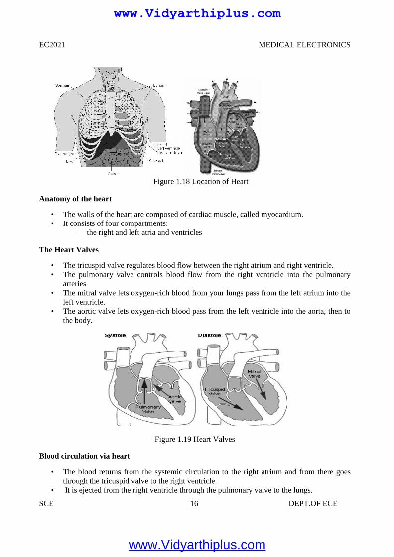
Figure 1.18 Location of Heart
Anatomy of the heart
• The walls of the heart are composed of cardiac muscle, called myocardium.• It consists of four compartments:
– the right and left atria and ventricles
The Heart Valves
• The tricuspid valve regulates blood flow between the right atrium and right ventricle.• The pulmonary valve controls blood flow from the right ventricle into the pulmonary
arteries• The mitral valve lets oxygen-rich blood from your lungs pass from the left atrium into the
left ventricle.• The aortic valve lets oxygen-rich blood pass from the left ventricle into the aorta, then to
the body.
Figure 1.19 Heart Valves
Blood circulation via heart
• The blood returns from the systemic circulation to the right atrium and from there goesthrough the tricuspid valve to the right ventricle.
• It is ejected from the right ventricle through the pulmonary valve to the lungs.
EC2021 MEDICAL ELECTRONICS
SCE 16 DEPT.OF ECE
Figure 1.18 Location of Heart
Anatomy of the heart
• The walls of the heart are composed of cardiac muscle, called myocardium.• It consists of four compartments:
– the right and left atria and ventricles
The Heart Valves
• The tricuspid valve regulates blood flow between the right atrium and right ventricle.• The pulmonary valve controls blood flow from the right ventricle into the pulmonary
arteries• The mitral valve lets oxygen-rich blood from your lungs pass from the left atrium into the
left ventricle.• The aortic valve lets oxygen-rich blood pass from the left ventricle into the aorta, then to
the body.
Figure 1.19 Heart Valves
Blood circulation via heart
• The blood returns from the systemic circulation to the right atrium and from there goesthrough the tricuspid valve to the right ventricle.
• It is ejected from the right ventricle through the pulmonary valve to the lungs.
www.Vidyarthiplus.com
www.Vidyarthiplus.com
EC2021 MEDICAL ELECTRONICS
SCE 17 DEPT.OF ECE
• Oxygenated blood returns from the lungs to the left atrium, and from there through themitral valve to the left ventricle.
• Finally blood is pumped through the aortic valve to the aorta and the systemiccirculation.
Electrical activation of the heart
• In the heart muscle cell, or myocyte, electric activation takes place by means of the samemechanism as in the nerve cell, i.e., from the inflow of Na ions across the cell membrane.
• The amplitude of the action potential is also similar, being 100 mV for both nerve andmuscle
• The duration of the cardiac impulse is, however, two orders of magnitude longer than ineither nerve cell or sceletal muscle cell.
• As in the nerve cell, repolarization is a consequence of the outflow of K ions.• The duration of the action impulse is about 300 ms
Mechanical contraction of Cardiac Muscle
• Associated with the electric activation of cardiac muscle cell is its mechanicalcontraction, which occurs a little later.
• An important distinction between cardiac muscle tissue and skeletal muscle is that incardiac muscle, activation can propagate from one cell to another in any direction.
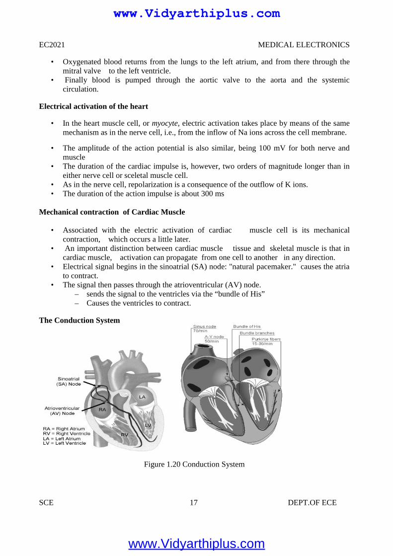
• Electrical signal begins in the sinoatrial (SA) node: "natural pacemaker." causes the atriato contract.
• The signal then passes through the atrioventricular (AV) node.– sends the signal to the ventricles via the “bundle of His”– Causes the ventricles to contract.
The Conduction System
Figure 1.20 Conduction System
EC2021 MEDICAL ELECTRONICS
SCE 17 DEPT.OF ECE
• Oxygenated blood returns from the lungs to the left atrium, and from there through themitral valve to the left ventricle.
• Finally blood is pumped through the aortic valve to the aorta and the systemiccirculation.
Electrical activation of the heart
• In the heart muscle cell, or myocyte, electric activation takes place by means of the samemechanism as in the nerve cell, i.e., from the inflow of Na ions across the cell membrane.
• The amplitude of the action potential is also similar, being 100 mV for both nerve andmuscle
• The duration of the cardiac impulse is, however, two orders of magnitude longer than ineither nerve cell or sceletal muscle cell.
• As in the nerve cell, repolarization is a consequence of the outflow of K ions.• The duration of the action impulse is about 300 ms
Mechanical contraction of Cardiac Muscle
• Associated with the electric activation of cardiac muscle cell is its mechanicalcontraction, which occurs a little later.
• An important distinction between cardiac muscle tissue and skeletal muscle is that incardiac muscle, activation can propagate from one cell to another in any direction.
• Electrical signal begins in the sinoatrial (SA) node: "natural pacemaker." causes the atriato contract.
• The signal then passes through the atrioventricular (AV) node.– sends the signal to the ventricles via the “bundle of His”– Causes the ventricles to contract.
The Conduction System
Figure 1.20 Conduction System
www.Vidyarthiplus.com
www.Vidyarthiplus.com
EC2021 MEDICAL ELECTRONICS
SCE 18 DEPT.OF ECE
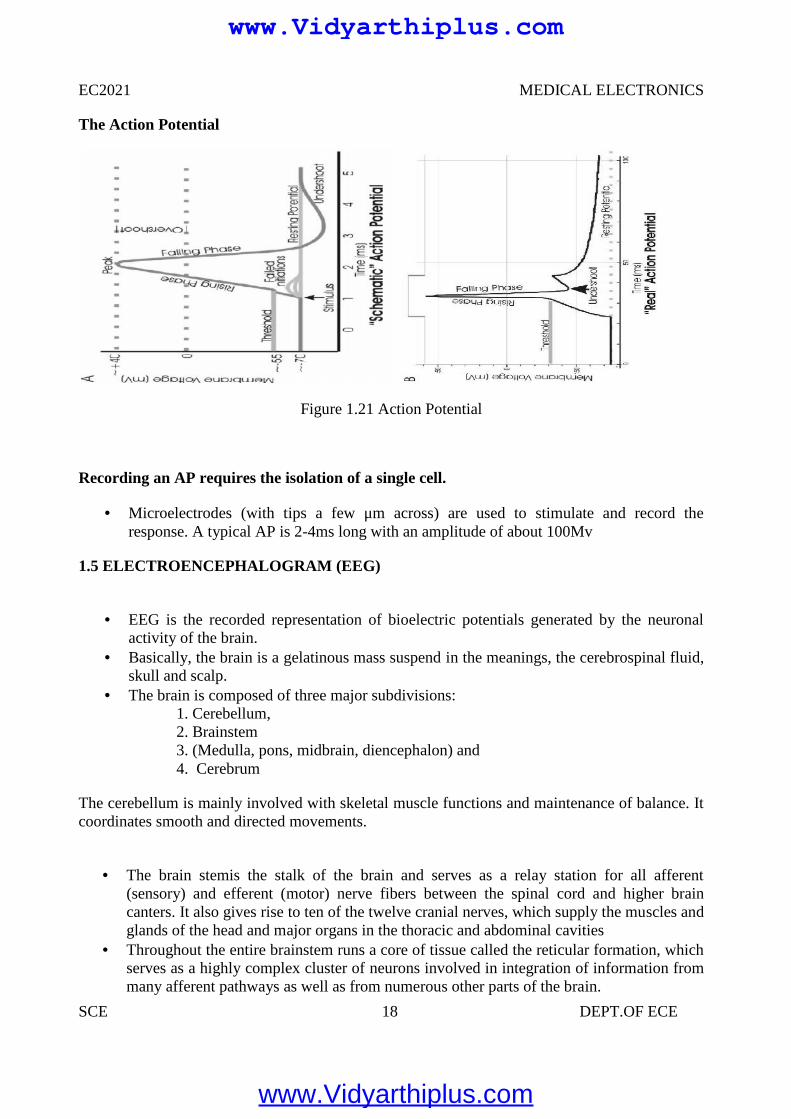
The Action Potential
Figure 1.21 Action Potential
Recording an AP requires the isolation of a single cell.
Microelectrodes (with tips a few μm across) are used to stimulate and record theresponse. A typical AP is 2-4ms long with an amplitude of about 100Mv
1.5 ELECTROENCEPHALOGRAM (EEG)
EEG is the recorded representation of bioelectric potentials generated by the neuronalactivity of the brain.
Basically, the brain is a gelatinous mass suspend in the meanings, the cerebrospinal fluid,skull and scalp.
The brain is composed of three major subdivisions:1. Cerebellum,2. Brainstem3. (Medulla, pons, midbrain, diencephalon) and4. Cerebrum
The cerebellum is mainly involved with skeletal muscle functions and maintenance of balance. Itcoordinates smooth and directed movements.
The brain stemis the stalk of the brain and serves as a relay station for all afferent(sensory) and efferent (motor) nerve fibers between the spinal cord and higher braincanters. It also gives rise to ten of the twelve cranial nerves, which supply the muscles andglands of the head and major organs in the thoracic and abdominal cavities
Throughout the entire brainstem runs a core of tissue called the reticular formation, whichserves as a highly complex cluster of neurons involved in integration of information frommany afferent pathways as well as from numerous other parts of the brain.
EC2021 MEDICAL ELECTRONICS
SCE 18 DEPT.OF ECE
The Action Potential
Figure 1.21 Action Potential
Recording an AP requires the isolation of a single cell.
Microelectrodes (with tips a few μm across) are used to stimulate and record theresponse. A typical AP is 2-4ms long with an amplitude of about 100Mv
1.5 ELECTROENCEPHALOGRAM (EEG)
EEG is the recorded representation of bioelectric potentials generated by the neuronalactivity of the brain.
Basically, the brain is a gelatinous mass suspend in the meanings, the cerebrospinal fluid,skull and scalp.
The brain is composed of three major subdivisions:1. Cerebellum,2. Brainstem3. (Medulla, pons, midbrain, diencephalon) and4. Cerebrum
The cerebellum is mainly involved with skeletal muscle functions and maintenance of balance. Itcoordinates smooth and directed movements.
The brain stemis the stalk of the brain and serves as a relay station for all afferent(sensory) and efferent (motor) nerve fibers between the spinal cord and higher braincanters. It also gives rise to ten of the twelve cranial nerves, which supply the muscles andglands of the head and major organs in the thoracic and abdominal cavities
Throughout the entire brainstem runs a core of tissue called the reticular formation, whichserves as a highly complex cluster of neurons involved in integration of information frommany afferent pathways as well as from numerous other parts of the brain.
www.Vidyarthiplus.com
www.Vidyarthiplus.com
EC2021 MEDICAL ELECTRONICS
SCE 19 DEPT.OF ECE
The cerebrum consists of the right and left hemispheres. The outer part of the cerebralhemispheres, the cerebral cortex, is a cellular shell 1.5 – 4 mm thick of grey matter.
The cerebral cortex is highly convoluted and is the most complex integrating center of thenervous system. It brings together basic sensory information into meaningful perceptualimages and formulates ultimate decisions for control over the motor systems of the body.
The cerebral cortex is comprised of two layers: the pale cortex and the neocortex. The pale cortex is located on the median surface and the base of the brain and the
neocortex is present on the superior and lateral aspects of the cerebral hemispheres. The neocortex is composed of six layers and its cells can be categorized as pyramidal and
non-pyramidal cells. There are approximately 1010 neurons in the human cerebral cortex,about 75% of, which is pyramidal.
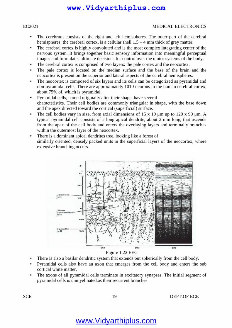
Pyramidal cells, named originally after their shape, have severalcharacteristics. Their cell bodies are commonly triangular in shape, with the base downand the apex directed toward the cortical (superficial) surface.
The cell bodies vary in size, from axial dimensions of 15 x 10 μm up to 120 x 90 μm. Atypical pyramidal cell consists of a long apical dendrite, about 2 mm long, that ascendsfrom the apex of the cell body and enters the overlaying layers and terminally brancheswithin the outermost layer of the neocortex.
There is a dominant apical dendrites tree, looking like a forest ofsimilarly oriented, densely packed units in the superficial layers of the neocortex, whereextensive branching occurs.
Figure 1.22 EEG There is also a basilar dendritic system that extends out spherically from the cell body. Pyramidal cells also have an axon that emerges from the cell body and enters the sub
cortical white matter. The axons of all pyramidal cells terminate in excitatory synapses. The initial segment of
pyramidal cells is unmyelinated,as their recurrent branches
www.Vidyarthiplus.com
www.Vidyarthiplus.com
EC2021 MEDICAL ELECTRONICS
SCE 20 DEPT.OF ECE
Axons of some pyramidal cells turn back toward the cortical surface to end via their manydendritic branches on the dendrites of other cells.
It has been shown by electrophysiological studies that under normal circumstances,propagating action potentials in axons do not contribute significantly to surface corticalrecordings.
There reason being that action potentials travel in large number of axons (running inmany different directions relative to the surface) in a temporally a synchronized way.Therefore, their net contribution to the surface EEG is minimal and negligible.
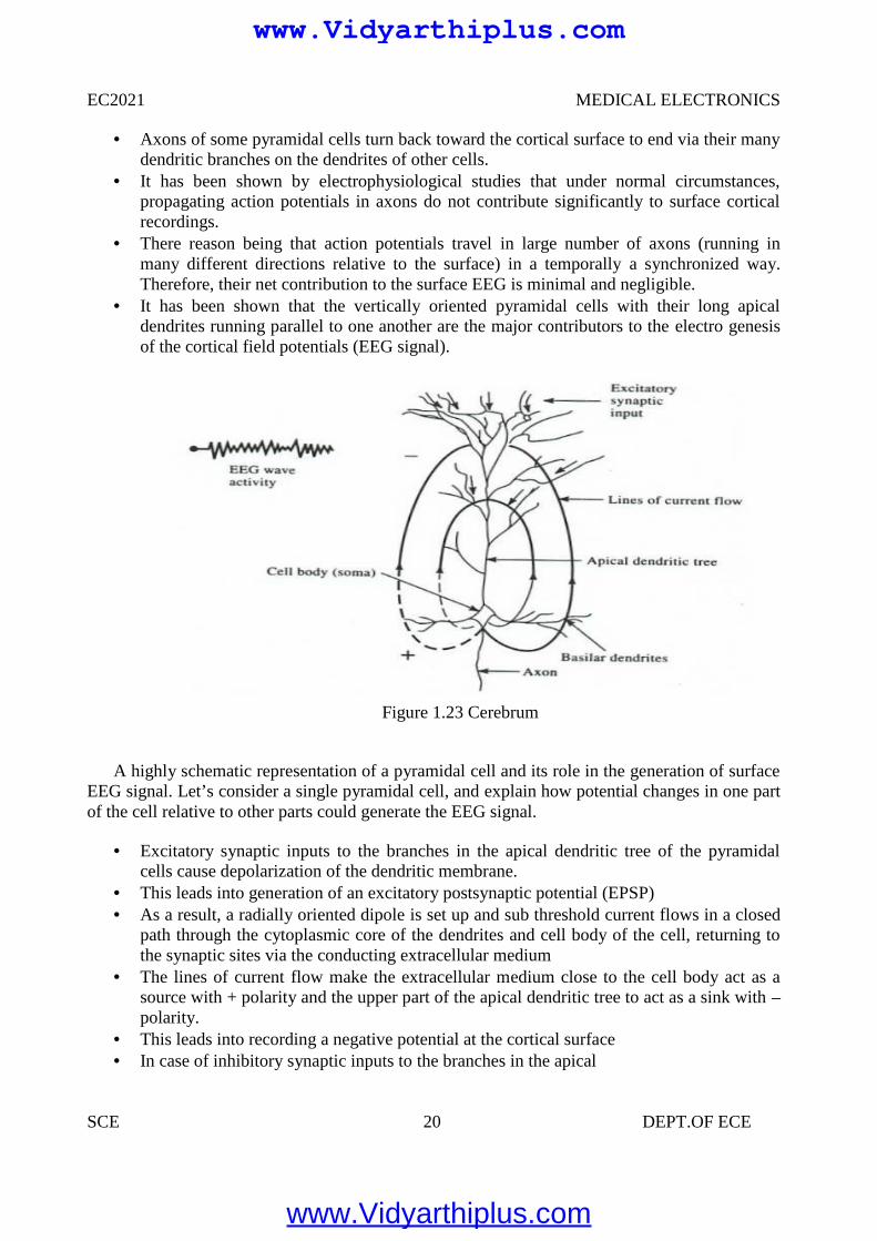
It has been shown that the vertically oriented pyramidal cells with their long apicaldendrites running parallel to one another are the major contributors to the electro genesisof the cortical field potentials (EEG signal).
Figure 1.23 Cerebrum
A highly schematic representation of a pyramidal cell and its role in the generation of surfaceEEG signal. Let’s consider a single pyramidal cell, and explain how potential changes in one partof the cell relative to other parts could generate the EEG signal.
Excitatory synaptic inputs to the branches in the apical dendritic tree of the pyramidalcells cause depolarization of the dendritic membrane.
This leads into generation of an excitatory postsynaptic potential (EPSP) As a result, a radially oriented dipole is set up and sub threshold current flows in a closed
path through the cytoplasmic core of the dendrites and cell body of the cell, returning tothe synaptic sites via the conducting extracellular medium
The lines of current flow make the extracellular medium close to the cell body act as asource with + polarity and the upper part of the apical dendritic tree to act as a sink with –polarity.
This leads into recording a negative potential at the cortical surface In case of inhibitory synaptic inputs to the branches in the apical
www.Vidyarthiplus.com
www.Vidyarthiplus.com
EC2021 MEDICAL ELECTRONICS
SCE 21 DEPT.OF ECE
dendritic tree, an inhibitory postsynaptic potential (IPSP) is generated with a reversal inthe polarity of the current dipole, which leads into a generation of a positive corticalrecording.
Therefore, the influence of a particular dendritic postsynaptic potential on the corticalrecording depends on its net excitatory or inhibitory effect and on its location relative tothe measurement site.
The EEG (electroencephalogram) signal is a recording of the electrical activity of the brain.The EEG signal recorded at the cortex or the scalp is generated by the polled activity of billionsof cortical and sub cortical regions. The origin of the EEG signal is based on the electricalactivity of the pyramidal cells. The EEG potentials primarily reflect the summated fluctuations ofexcitatory and inhibitory postsynaptic potentials in the pyramidal cells of the upper layers of thecerebral cortex. For reasons of geometry as well as because of extreme extracellular attenuation,action potentials from firings of pyramidal cells contribute only minimally or not all to thegeneration of the EEG signal.
All we need to contend ourselves with at this stages that the EEG or brain waves aresummation of neural depolarization sin the brain due to the stimuli from the five senses aswell as from thought processes (indeed a very complex source). More on this inphysiology in the Nervous System topic.
EEG potentials have random-appearing waveforms with peak-to-peak amplitudes rangingfrom less than 10 mV to over 100mV. Required bandwidth is from below 1 Hz to over100 Hz.
EEG is recorded with 3 types of electrodes:
1. Scalp2. Cortical Electrocardiogram (recording from surface of cortex)3. Depth Electrodes recording from depth of brain (thin insulated needles of various designs)
No matter where the recording is obtained from (scalp, cortex or depth of the brain), thefluctuating potentials represent a superposition of the volume conductor fields producedby a huge variety of active neuronal current-generators.
On the surface of the brain (i.e. Electrocardiogram), we can record voltages on the orderof 10 mV! But, typical EEG electrodes measure the electrical activity propagated throughskull bone and is attenuated from 1 to 100 μV.
EEG potentials vary as a function of position over the surface of the skull, making itnecessary to select sets of electrodes grouped around Frontal, Parietal, Temporal andOccipital lobes.
The EEG Signal
The character of the EEG signal is highly dependent on the degree of the activity of thecerebral cortex, i.e. waves change markedly between states of wakefulness and sleep.
Much of the time, EEGs are irregular and no general pattern can be observed. Othertimes, distinct patterns emerge
The EEG waveform is divided into four wave groups:
1. The Alpha Waves (α) 8-13 Hz
www.Vidyarthiplus.com
www.Vidyarthiplus.com
EC2021 MEDICAL ELECTRONICS
SCE 22 DEPT.OF ECE
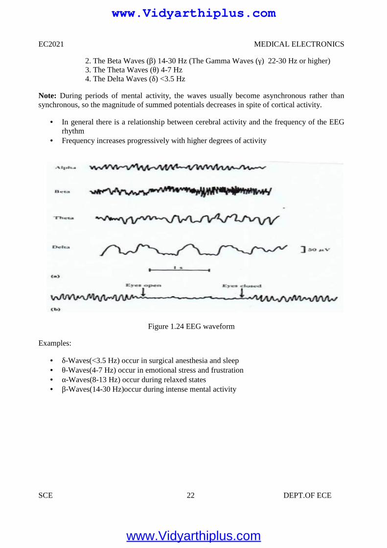
2. The Beta Waves (β) 14-30 Hz (The Gamma Waves (γ) 22-30 Hz or higher)3. The Theta Waves (θ) 4-7 Hz4. The Delta Waves (δ) <3.5 Hz
Note: During periods of mental activity, the waves usually become asynchronous rather thansynchronous, so the magnitude of summed potentials decreases in spite of cortical activity.
In general there is a relationship between cerebral activity and the frequency of the EEGrhythm
Frequency increases progressively with higher degrees of activity
Figure 1.24 EEG waveform
Examples:
δ-Waves(<3.5 Hz) occur in surgical anesthesia and sleep θ-Waves(4-7 Hz) occur in emotional stress and frustration α-Waves(8-13 Hz) occur during relaxed states β-Waves(14-30 Hz)occur during intense mental activity
www.Vidyarthiplus.com
www.Vidyarthiplus.com
EC2021 MEDICAL ELECTRONICS
SCE 23 DEPT.OF ECE
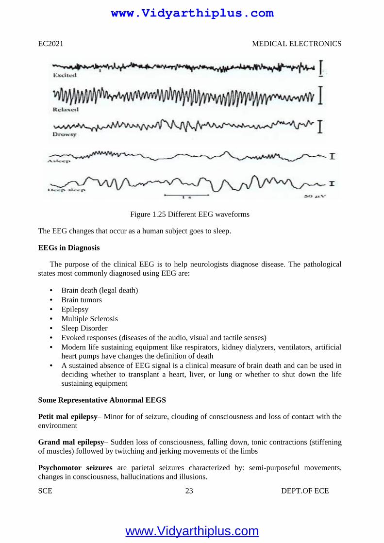
Figure 1.25 Different EEG waveforms
The EEG changes that occur as a human subject goes to sleep.
EEGs in Diagnosis
The purpose of the clinical EEG is to help neurologists diagnose disease. The pathologicalstates most commonly diagnosed using EEG are:
Brain death (legal death) Brain tumors Epilepsy Multiple Sclerosis Sleep Disorder Evoked responses (diseases of the audio, visual and tactile senses) Modern life sustaining equipment like respirators, kidney dialyzers, ventilators, artificial
heart pumps have changes the definition of death A sustained absence of EEG signal is a clinical measure of brain death and can be used in
deciding whether to transplant a heart, liver, or lung or whether to shut down the lifesustaining equipment
Some Representative Abnormal EEGS
Petit mal epilepsy– Minor for of seizure, clouding of consciousness and loss of contact with theenvironment
Grand mal epilepsy– Sudden loss of consciousness, falling down, tonic contractions (stiffeningof muscles) followed by twitching and jerking movements of the limbs
Psychomotor seizures are parietal seizures characterized by: semi-purposeful movements,changes in consciousness, hallucinations and illusions.
www.Vidyarthiplus.com
www.Vidyarthiplus.com
EC2021 MEDICAL ELECTRONICS
SCE 24 DEPT.OF ECE
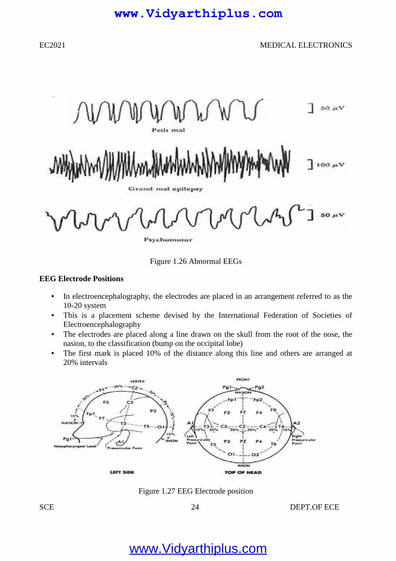
Figure 1.26 Abnormal EEGs
EEG Electrode Positions
In electroencephalography, the electrodes are placed in an arrangement referred to as the10-20 system
This is a placement scheme devised by the International Federation of Societies ofElectroencephalography
The electrodes are placed along a line drawn on the skull from the root of the nose, thenasion, to the classification (bump on the occipital lobe)
The first mark is placed 10% of the distance along this line and others are arranged at20% intervals
Figure 1.27 EEG Electrode position
www.Vidyarthiplus.com
www.Vidyarthiplus.com
EC2021 MEDICAL ELECTRONICS
SCE 25 DEPT.OF ECE
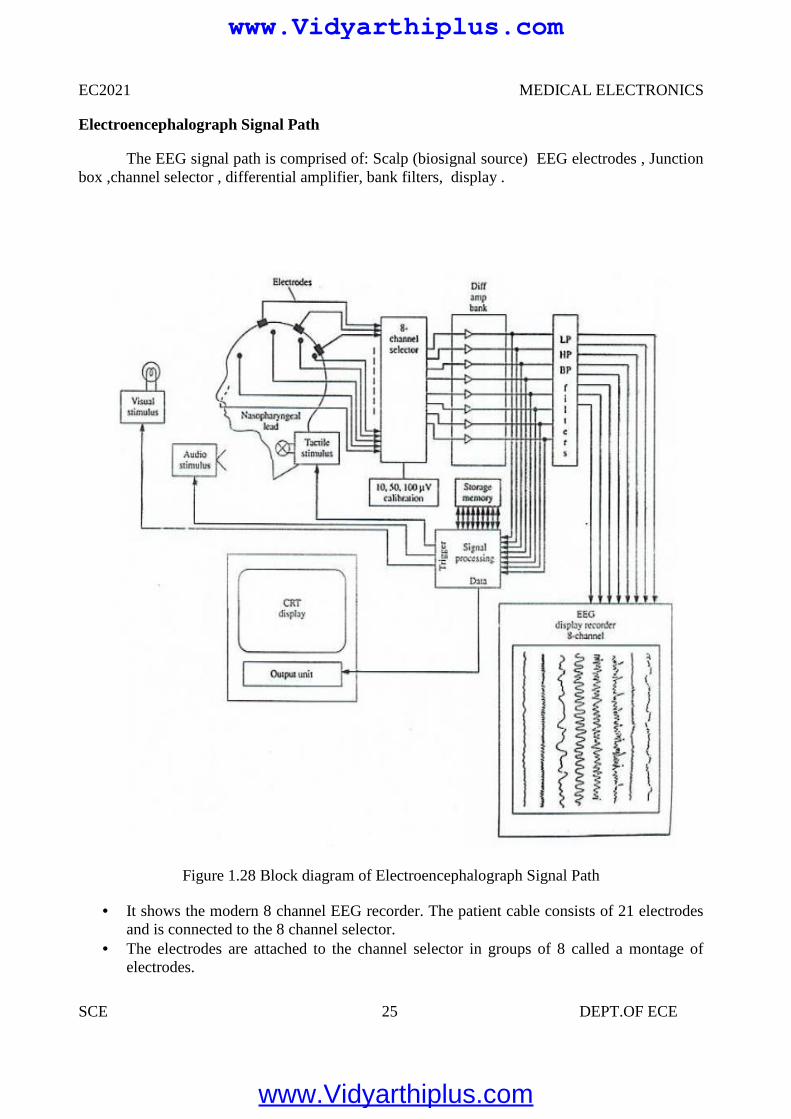
Electroencephalograph Signal Path
The EEG signal path is comprised of: Scalp (biosignal source) EEG electrodes , Junctionbox ,channel selector , differential amplifier, bank filters, display .
Figure 1.28 Block diagram of Electroencephalograph Signal Path
It shows the modern 8 channel EEG recorder. The patient cable consists of 21 electrodesand is connected to the 8 channel selector.
The electrodes are attached to the channel selector in groups of 8 called a montage ofelectrodes.
www.Vidyarthiplus.com
www.Vidyarthiplus.com
EC2021 MEDICAL ELECTRONICS
SCE 26 DEPT.OF ECE
The right ear electrode acts as reference electrode for the right brain electrodes and leftear electrode act as reference electrode for left brain electrodes.
The 50 Hz interference is reduced by employing differential amplifiers as preamplifierswith more than 80 dB CMRR and by use of 50 Hz notch filters.
The effect of notch filter on signal distortion is not so much because important EEGsignals have frequencies below 30 Hz.
The output voltage from the amplifier may either be applied directly to the eight channeldisplay through the filter bank or it may be stored as data on a tape recorder or in acomputer memory for further processing.
1.6 EMG (ELECTRO MYOGRAPH)
It is an instrument used for recording the electrical activity of the muscles to determinewhether the muscle is contracting or not. Study of neuromuscular function is also possible byusing EMG. Muscular contractions are caused by the depolarization of muscle fibers. Similarlythe recording of peripheral nerves action potentials is called as electro neurography.
ELECTRODES USED FOR EMG
Two types of electrodes:
Surface electrodes- Usually this electrode is used for EMG. But by using this electrode,it is not possible to take the deeper potential.
Needle electrodes – These are inserted into tissue or closer to tissue to measure theelectrical activity of muscle.
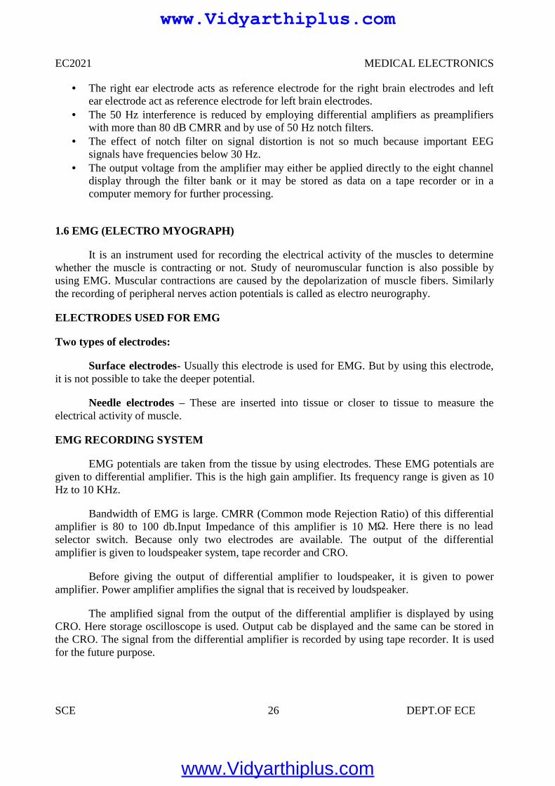
EMG RECORDING SYSTEM
EMG potentials are taken from the tissue by using electrodes. These EMG potentials aregiven to differential amplifier. This is the high gain amplifier. Its frequency range is given as 10Hz to 10 KHz.
Bandwidth of EMG is large. CMRR (Common mode Rejection Ratio) of this differentialamplifier is 80 to 100 db.Input Impedance of this amplifier is 10 MΩ. Here there is no leadselector switch. Because only two electrodes are available. The output of the differentialamplifier is given to loudspeaker system, tape recorder and CRO.
Before giving the output of differential amplifier to loudspeaker, it is given to poweramplifier. Power amplifier amplifies the signal that is received by loudspeaker.
The amplified signal from the output of the differential amplifier is displayed by usingCRO. Here storage oscilloscope is used. Output cab be displayed and the same can be stored inthe CRO. The signal from the differential amplifier is recorded by using tape recorder. It is usedfor the future purpose.
www.Vidyarthiplus.com
www.Vidyarthiplus.com
EC2021 MEDICAL ELECTRONICS
SCE 27 DEPT.OF ECE
Figure 1.29 EMG Recording System
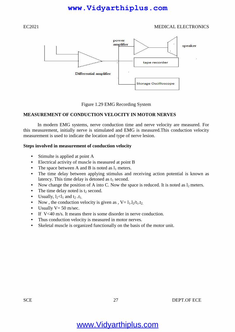
MEASUREMENT OF CONDUCTION VELOCITY IN MOTOR NERVES
In modern EMG systems, nerve conduction time and nerve velocity are measured. Forthis measurement, initially nerve is stimulated and EMG is measured.This conduction velocitymeasurement is used to indicate the location and type of nerve lesion.
Steps involved in measurement of conduction velocity
Stimulte is applied at point A Electrical activity of muscle is measured at point B The space between A and B is noted as l1 meters. The time delay between applying stimulus and receiving action potential is known as
latency. This time delay is detoned as t1 second. Now change the position of A into C. Now the space is reduced. It is noted as l2 meters. The time delay noted is t2 second. Usually, l2<l1 and t2 <t1.
Now , the conduction velocity is given as , V= l1-l2/t1-t2.
Usually V= 50 m/sec. If V<40 m/s. It means there is some disorder in nerve conduction. Thus conduction velocity is measured in motor nerves. Skeletal muscle is organized functionally on the basis of the motor unit.
www.Vidyarthiplus.com
www.Vidyarthiplus.com
EC2021 MEDICAL ELECTRONICS
SCE 28 DEPT.OF ECE
Figure 1.30 Conduction Velocity In Motor Nerves
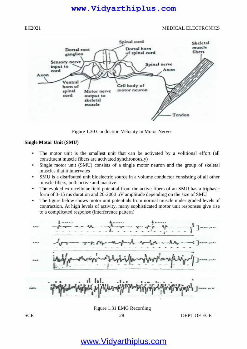
Single Motor Unit (SMU)
The motor unit is the smallest unit that can be activated by a volitional effort (allconstituent muscle fibers are activated synchronously)
Single motor unit (SMU) consists of a single motor neuron and the group of skeletalmuscles that it innervates
SMU is a distributed unit bioelectric source in a volume conductor consisting of all othermuscle fibers, both active and inactive.
The evoked extracellular field potential from the active fibers of an SMU has a triphasicform of 3-15 ms duration and 20-2000 μV amplitude depending on the size of SMU
The figure below shows motor unit potentials from normal muscle under graded levels ofcontraction. At high levels of activity, many sophisticated motor unit responses give riseto a complicated response (interference pattern)
Figure 1.31 EMG Recording
www.Vidyarthiplus.com
www.Vidyarthiplus.com
EC2021 MEDICAL ELECTRONICS
SCE 29 DEPT.OF ECE
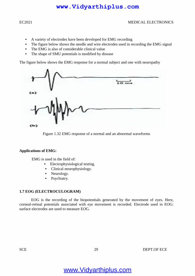
A variety of electrodes have been developed for EMG recording The figure below shows the needle and wire electrodes used in recording the EMG signal The EMG is also of considerable clinical value The shape of SMU potentials is modified by disease
The figure below shows the EMG response for a normal subject and one with neuropathy
Figure 1.32 EMG response of a normal and an abnormal waveforms
Applications of EMG:
EMG is used in the field of: Electrophysiological testing. Clinical neurophysiology. Neurology. Psychiatry.
1.7 EOG (ELECTROCULOGRAM)
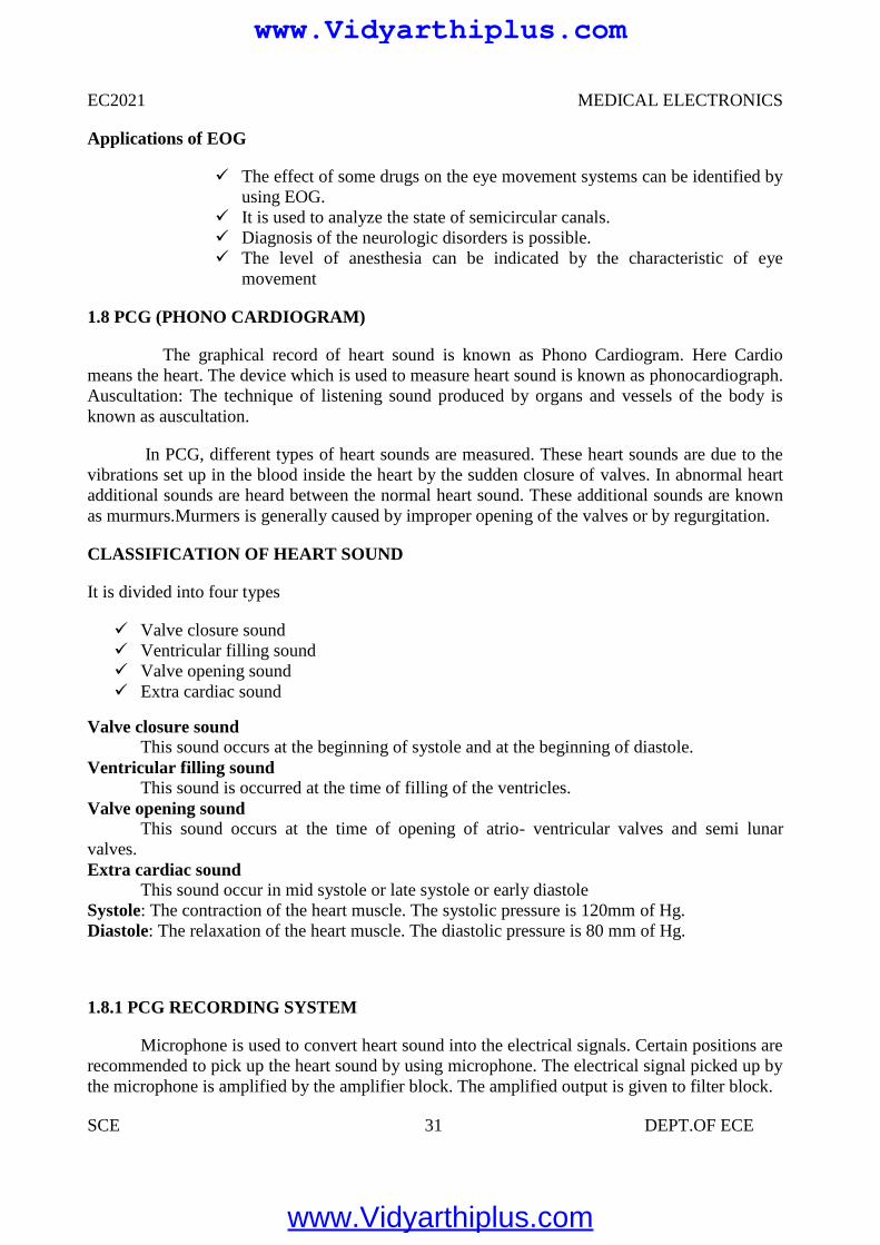
EOG is the recording of the biopotentials generated by the movement of eyes. Here,corneal-retinal potentials associated with eye movement is recorded. Electrode used in EOG:surface electrodes are used to measure EOG.
www.Vidyarthiplus.com
www.Vidyarthiplus.com
EC2021 MEDICAL ELECTRONICS
SCE 30 DEPT.OF ECE
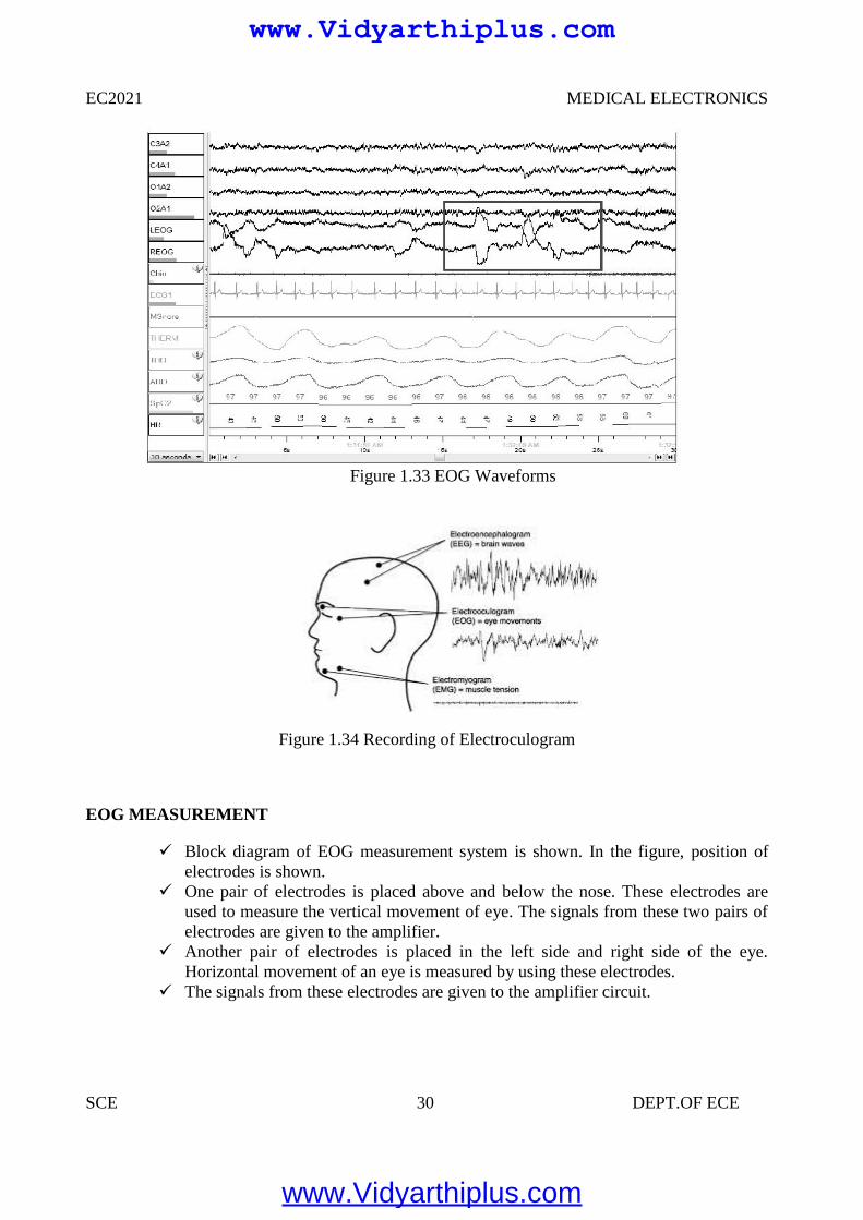
Figure 1.33 EOG Waveforms
Figure 1.34 Recording of Electroculogram
EOG MEASUREMENT
Block diagram of EOG measurement system is shown. In the figure, position ofelectrodes is shown.
One pair of electrodes is placed above and below the nose. These electrodes areused to measure the vertical movement of eye. The signals from these two pairs ofelectrodes are given to the amplifier.
Another pair of electrodes is placed in the left side and right side of the eye.Horizontal movement of an eye is measured by using these electrodes.
The signals from these electrodes are given to the amplifier circuit.
EC2021 MEDICAL ELECTRONICS
SCE 30 DEPT.OF ECE
Figure 1.33 EOG Waveforms
Figure 1.34 Recording of Electroculogram
EOG MEASUREMENT
Block diagram of EOG measurement system is shown. In the figure, position ofelectrodes is shown.
One pair of electrodes is placed above and below the nose. These electrodes areused to measure the vertical movement of eye. The signals from these two pairs ofelectrodes are given to the amplifier.
Another pair of electrodes is placed in the left side and right side of the eye.Horizontal movement of an eye is measured by using these electrodes.
The signals from these electrodes are given to the amplifier circuit.
www.Vidyarthiplus.com
www.Vidyarthiplus.com
EC2021 MEDICAL ELECTRONICS
SCE 31 DEPT.OF ECE
Applications of EOG
The effect of some drugs on the eye movement systems can be identified byusing EOG.
It is used to analyze the state of semicircular canals. Diagnosis of the neurologic disorders is possible. The level of anesthesia can be indicated by the characteristic of eye
movement
1.8 PCG (PHONO CARDIOGRAM)
The graphical record of heart sound is known as Phono Cardiogram. Here Cardiomeans the heart. The device which is used to measure heart sound is known as phonocardiograph.Auscultation: The technique of listening sound produced by organs and vessels of the body isknown as auscultation.
In PCG, different types of heart sounds are measured. These heart sounds are due to thevibrations set up in the blood inside the heart by the sudden closure of valves. In abnormal heartadditional sounds are heard between the normal heart sound. These additional sounds are knownas murmurs.Murmers is generally caused by improper opening of the valves or by regurgitation.
CLASSIFICATION OF HEART SOUND
It is divided into four types
Valve closure sound Ventricular filling sound Valve opening sound Extra cardiac sound
Valve closure soundThis sound occurs at the beginning of systole and at the beginning of diastole.
Ventricular filling soundThis sound is occurred at the time of filling of the ventricles.
Valve opening soundThis sound occurs at the time of opening of atrio- ventricular valves and semi lunar
valves.Extra cardiac sound
This sound occur in mid systole or late systole or early diastoleSystole: The contraction of the heart muscle. The systolic pressure is 120mm of Hg.Diastole: The relaxation of the heart muscle. The diastolic pressure is 80 mm of Hg.
1.8.1 PCG RECORDING SYSTEM
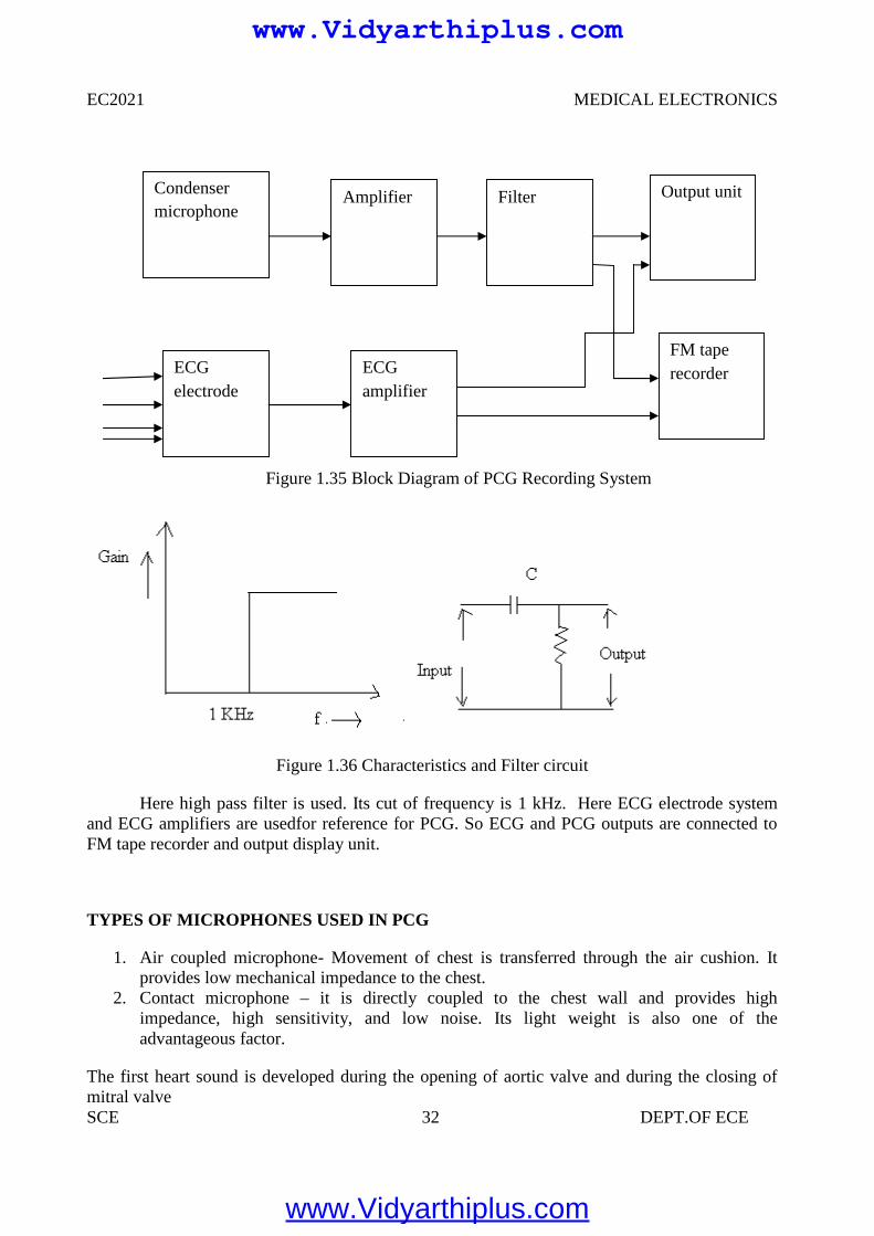
Microphone is used to convert heart sound into the electrical signals. Certain positions arerecommended to pick up the heart sound by using microphone. The electrical signal picked up bythe microphone is amplified by the amplifier block. The amplified output is given to filter block.
www.Vidyarthiplus.com
www.Vidyarthiplus.com
EC2021 MEDICAL ELECTRONICS
SCE 32 DEPT.OF ECE
Figure 1.35 Block Diagram of PCG Recording System
Figure 1.36 Characteristics and Filter circuit
Here high pass filter is used. Its cut of frequency is 1 kHz. Here ECG electrode systemand ECG amplifiers are usedfor reference for PCG. So ECG and PCG outputs are connected toFM tape recorder and output display unit.
TYPES OF MICROPHONES USED IN PCG
1. Air coupled microphone- Movement of chest is transferred through the air cushion. Itprovides low mechanical impedance to the chest.
2. Contact microphone – it is directly coupled to the chest wall and provides highimpedance, high sensitivity, and low noise. Its light weight is also one of theadvantageous factor.
The first heart sound is developed during the opening of aortic valve and during the closing ofmitral valve
Condensermicrophone
Amplifier
ECGelectrode
Filter
ECGamplifier
FM taperecorder
Output unit
www.Vidyarthiplus.com
www.Vidyarthiplus.com
EC2021 MEDICAL ELECTRONICS
SCE 33 DEPT.OF ECE
PCG waveform
Frequency of first heart sound consists of 30 to 45 Hz. Second heart sound is usuallyhigher in pitch than the first. Its frequency range is 50Hz to 70 Hz. Third heart sound is extremelyweak vibrate sound is extremely weak vibration. Its frequency is below 600 Hz.
Aortic stenos are murmur occurred when the blood is ejected from the left ventriclethrough aortic valve due to resistance to ejection, the pressure in the left ventricle increased. Soturbulent blood flow occur.This turbulent blood impinging the aortic valve. So intense vibrationis produced. It produces loud murmur.
Mitral regurgitation murmur- In this murmur, blood flows in backward direction through themitral valve during systole.
Aortic regurgitation murmur – During diastole, sound is heard. In diastole blood flows in thebackward direction from aorta to left ventricles when valves are damaged, then this sound isheard.
Mitral stenosis murmur – This murmur is produced when blood is passed from left atrium toleft ventricle. This sound is very weak.
www.Vidyarthiplus.com
www.Vidyarthiplus.com
EC2021 MEDICAL ELECTRONICS
SCE 34 DEPT.OF ECE
UNIT II
BIO-CHEMICAL AND NON ELECTRICAL PARAMETER MEASUREMENT
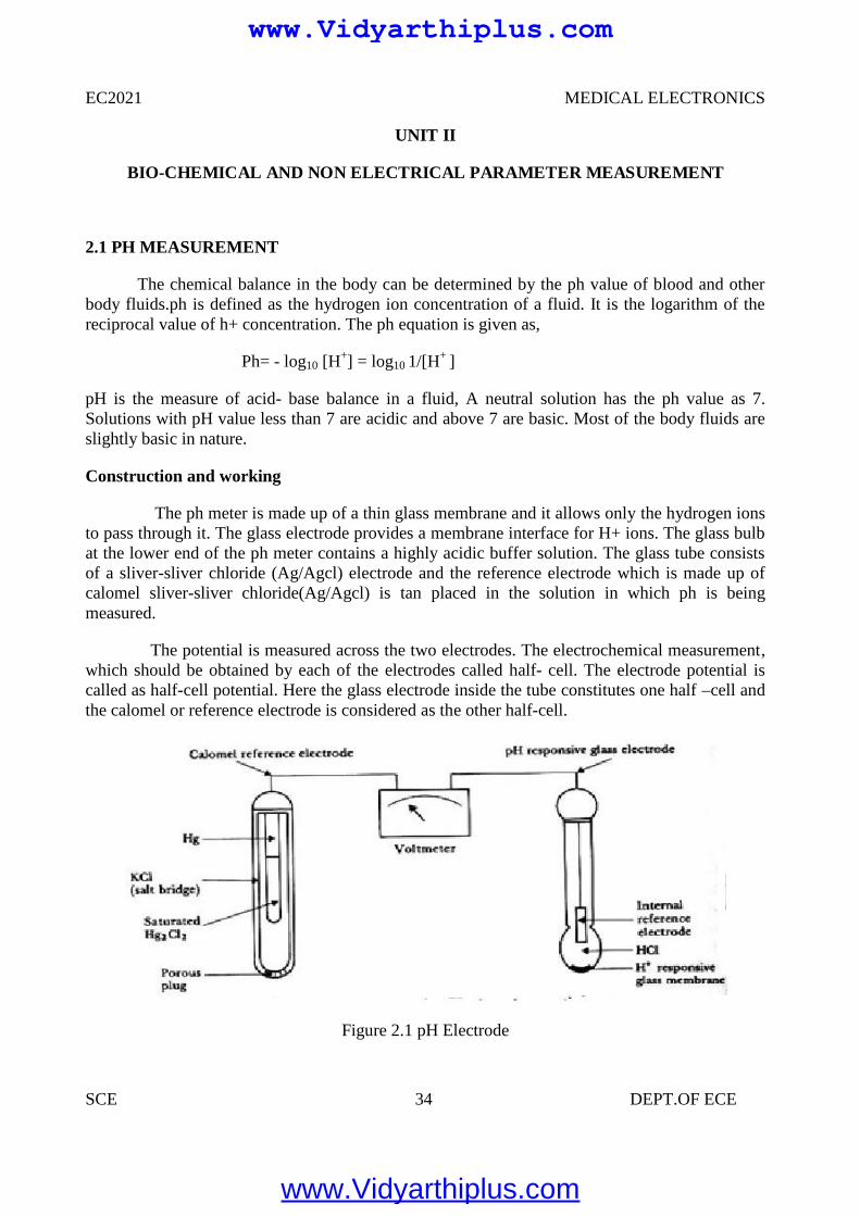
2.1 PH MEASUREMENT
The chemical balance in the body can be determined by the ph value of blood and otherbody fluids.ph is defined as the hydrogen ion concentration of a fluid. It is the logarithm of thereciprocal value of h+ concentration. The ph equation is given as,
Ph= - log10 [H+] = log10 1/[H+ ]
pH is the measure of acid- base balance in a fluid, A neutral solution has the ph value as 7.Solutions with pH value less than 7 are acidic and above 7 are basic. Most of the body fluids areslightly basic in nature.
Construction and working
The ph meter is made up of a thin glass membrane and it allows only the hydrogen ionsto pass through it. The glass electrode provides a membrane interface for H+ ions. The glass bulbat the lower end of the ph meter contains a highly acidic buffer solution. The glass tube consistsof a sliver-sliver chloride (Ag/Agcl) electrode and the reference electrode which is made up ofcalomel sliver-sliver chloride(Ag/Agcl) is tan placed in the solution in which ph is beingmeasured.
The potential is measured across the two electrodes. The electrochemical measurement,which should be obtained by each of the electrodes called half- cell. The electrode potential iscalled as half-cell potential. Here the glass electrode inside the tube constitutes one half –cell andthe calomel or reference electrode is considered as the other half-cell.
Figure 2.1 pH Electrode
www.Vidyarthiplus.com
www.Vidyarthiplus.com
EC2021 MEDICAL ELECTRONICS
SCE 35 DEPT.OF ECE
For easier ph measurement combination electrodes are used. In this type both the activeglass electrode and reference electrode are present in the same meter. The glass electrodes aresuitable only to measure ph values around 7. Since this type of glass electrodes produceconsiderable errors during the measurement of high Ph values, special type of Ph electrodes areused. After every measurement the pH meter is washed with 20% ammonium biflouride solution,for accurate results. The Ph meter with hydroscopic glass absorbs water readily and provides bestpH value.
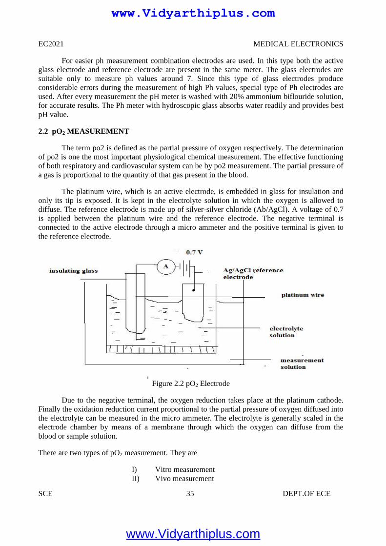
2.2 pO2 MEASUREMENT
The term po2 is defined as the partial pressure of oxygen respectively. The determinationof po2 is one the most important physiological chemical measurement. The effective functioningof both respiratory and cardiovascular system can be by po2 measurement. The partial pressure ofa gas is proportional to the quantity of that gas present in the blood.
The platinum wire, which is an active electrode, is embedded in glass for insulation andonly its tip is exposed. It is kept in the electrolyte solution in which the oxygen is allowed todiffuse. The reference electrode is made up of silver-silver chloride (Ab/AgCl). A voltage of 0.7is applied between the platinum wire and the reference electrode. The negative terminal isconnected to the active electrode through a micro ammeter and the positive terminal is given tothe reference electrode.
Figure 2.2 pO2 Electrode
Due to the negative terminal, the oxygen reduction takes place at the platinum cathode.Finally the oxidation reduction current proportional to the partial pressure of oxygen diffused intothe electrolyte can be measured in the micro ammeter. The electrolyte is generally scaled in theelectrode chamber by means of a membrane through which the oxygen can diffuse from theblood or sample solution.
There are two types of pO2 measurement. They are
I) Vitro measurementII) Vivo measurement
www.Vidyarthiplus.com
www.Vidyarthiplus.com
EC2021 MEDICAL ELECTRONICS
SCE 36 DEPT.OF ECE
In case of dark electrode the platinum cathode and the reference electrode is present in a singleunit. This electrode is used for vitro and vivo measurements.
In Vitro Measurements
In this method the blood sample is taken and the measurement for oxygen saturation ismade in the laboratory. The electrode is placed in the sample blood solution and the pO2 value isdetermined.
In Vivo Measurements
In this method the oxygen saturation is determined while the blood is flowing in thecirculatory system. A micro version of the pO2 electrode is placed at the tip of the catheter so thatit can be inserted into various parts of the heart or circulatory system.
The pO2 measurement also has some disadvantages in it. The reduction process in theplatinum cathode removes a finite amount of the oxygen from the cathode. And there is a gradualreduction of current with respect to time. However careful design and proper procedures inmodern pO2 electrodes reduce the errors.
2.3 pCO2 MEASUREMENT
The term pco2 is defined as the partial pressure of carbon dioxide respectively. Thedetermination of pco2 is one the most important physiological chemical measurement. Theeffective functioning of both respiratory and cardiovascular system can be by pco2 measurement.The partial pressure of a gas is proportional to the quantity of that gas present in the blood.
The partial pressure of carbon dioxide can be measured with the help of pCO2 electrodes.Since there is a linear relationship between the logarithm of pCO2 and pH of a solution. ThepCO2 measurement is made by surrounding a pH electrode with a membrane selectivelypermeable to CO2.
The modern improved pCO2 electrode is called as severinghous electrode. In thiselectrode the membrane permeable to CO2 is made up of Teflon which is not permeable to otherions which affects the pH value. The space between the Teflon and glass contains a matrix layerwhich allows only the CO2 gas molecules to diffuse through it.
One of the demerits in older CO2 electrode is, it requires a length of time for the CO2
molecules to diffuse through the membrane. The modern CO2 electrode is designed in such a wayto overcome this demerit. Here the CO2 molecules diffuse rapidly through the membrane and themeasurement can be done easily.
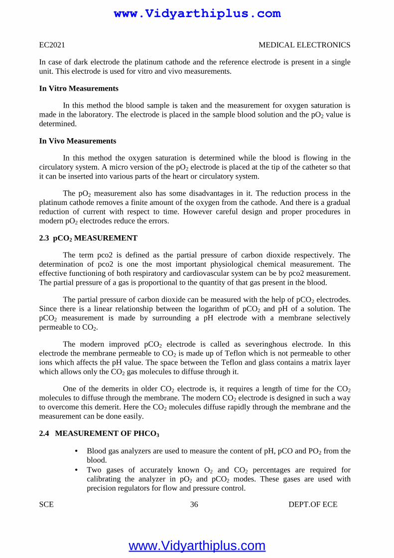
2.4 MEASUREMENT OF PHCO3
Blood gas analyzers are used to measure the content of pH, pCO and PO2 from theblood.
Two gases of accurately known O2 and CO2 percentages are required forcalibrating the analyzer in pO2 and pCO2 modes. These gases are used withprecision regulators for flow and pressure control.
www.Vidyarthiplus.com
www.Vidyarthiplus.com
EC2021 MEDICAL ELECTRONICS
SCE 37 DEPT.OF ECE
Two standard buffers of known pH are required for calibration of the analyzer inthe pH mode.
Input signal to the calculator is obtained from the outputs of the pH and pCO2
amplifiers The outputs are adjusted by multiplying with a constant and are given to an adder
circuit The output of adder is passed to antilog generators circuit. Then it is passed to
A/D converter for display. Resistance R is used to adjust zero at the output. Total CO2 is calculated by summing the output signals of the calculators and the
output of the pCO2 amplifier
Figure 2.3 circuit diagram of computation of bicarbonate
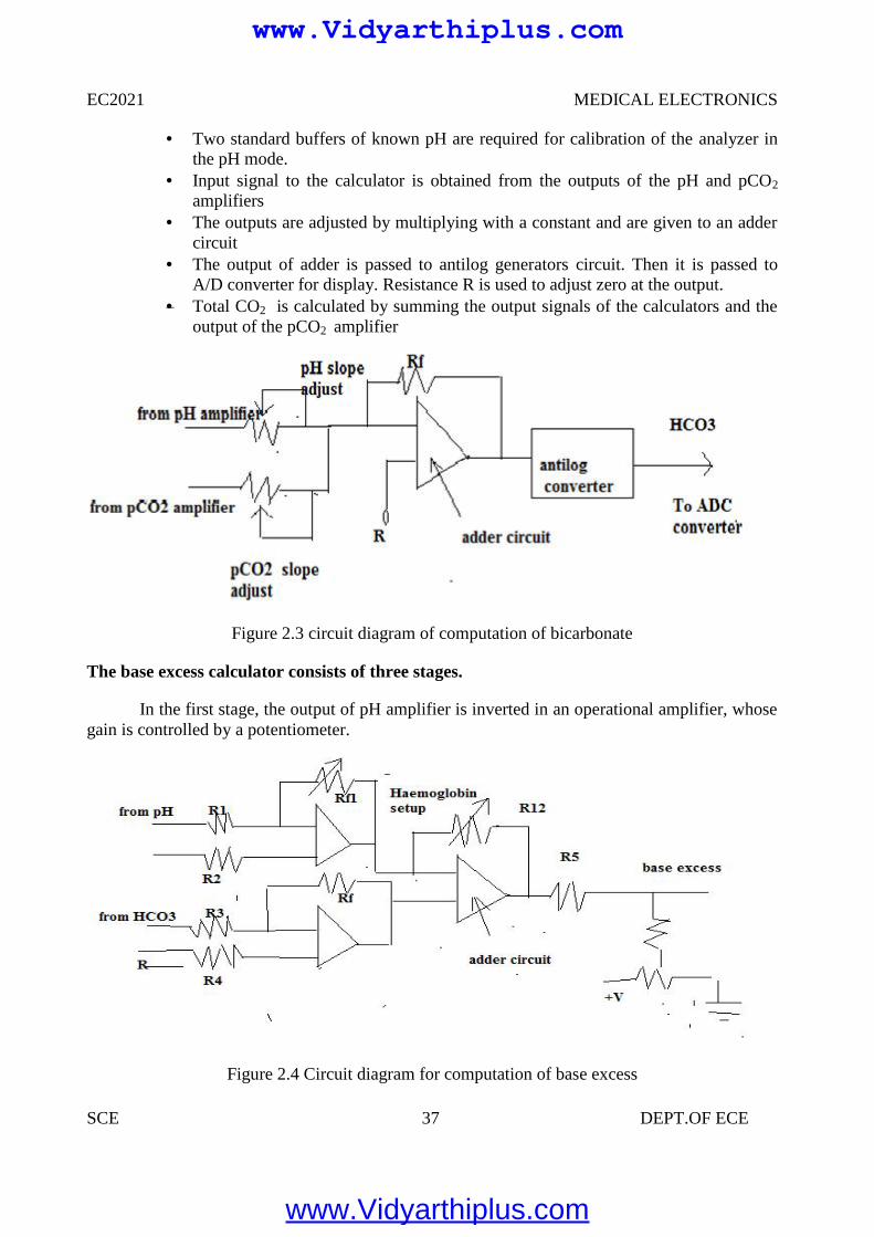
The base excess calculator consists of three stages.
In the first stage, the output of pH amplifier is inverted in an operational amplifier, whosegain is controlled by a potentiometer.
Figure 2.4 Circuit diagram for computation of base excess
www.Vidyarthiplus.com
www.Vidyarthiplus.com
EC2021 MEDICAL ELECTRONICS
SCE 38 DEPT.OF ECE
The output of HCO3—calculator is inverted in the second stage.
The third stage is a summing amplifier A3 whose output is given to A/D converter, that gives adigital read out.
2.5 ELECTROPHORESIS
In clinical laboratories, various devices are used based on the electrophoretic principle.These devices are used for the following applications.
To measure the quantity of protein in plasma, urine, etc. To separate enzymes into their components is enzymes. To identify antibodies.
Basic principle
Electrophoresis is defined as the movement of a solid phase with respect to a liquid. Thebuffer solution is used to carry the current and to maintain the pH value of the solution as aconstant one during the migration.
In this title, zone electrophoresis is explained. In this technique, the sample is applied tothe medium and under the effect of the electric field, group of particles that are similar in charge,size, and shape migrate at the same rate. So the particles are separated into zones.
Factors Affect the Speed of Migration
Magnitude of charge:
The mobility of a given particle is directly related to the net magnitude of the particlescharge. Mobility is defined as, the distance in cm, a particle moves in unit time per unit fieldstrength.
Ionic Strength of Buffer
If the buffer is more concentrated then the migration of the particles is slow. Because, ifgreater the proportion of buffer ions present, then greater the proportion of the current they carry.
Temperature:
Mobility is directly related to temperature. Heat is produced when the current flowsthrough the resistance of the medium. So, the temperature of the medium is increased andresistance is decreased. Finally, the rate of migration is increased.
The water is evaporated from the surface of the medium due to heat. So, the concentrationof particle is increased. Finally the rate of migration is increased. When the gel is used as amedium; this heat will create a problem. So, for this medium, constant current sources are used tominimize the heat production.
Time: The distance of migration is related to the time period during which electrophoresis takesplace.
www.Vidyarthiplus.com
www.Vidyarthiplus.com
EC2021 MEDICAL ELECTRONICS
SCE 39 DEPT.OF ECE
Types of Support Media:
Cellulose acetate, starch gel and sucrose are used as support media in variouselectrophoretic applications. We can see the cellulose acetate electrophoresis in the followingsections.
Cellulose Acetate Electrophoresis
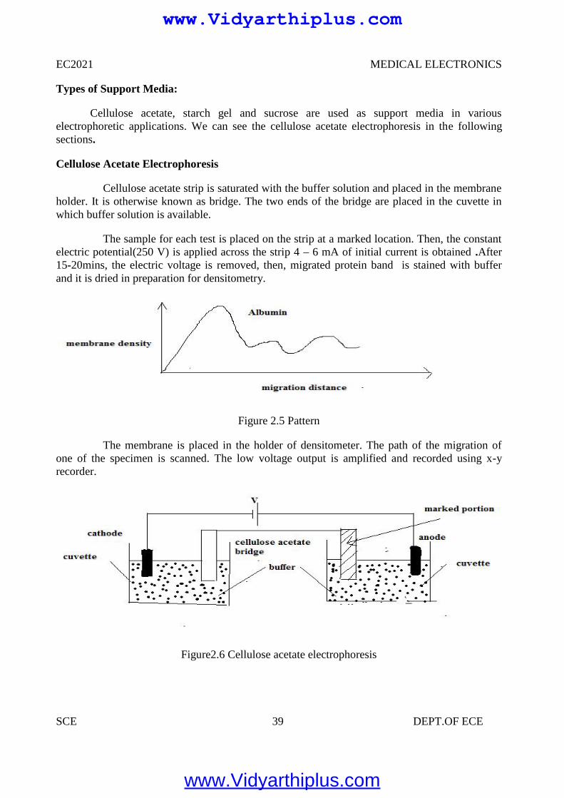
Cellulose acetate strip is saturated with the buffer solution and placed in the membraneholder. It is otherwise known as bridge. The two ends of the bridge are placed in the cuvette inwhich buffer solution is available.
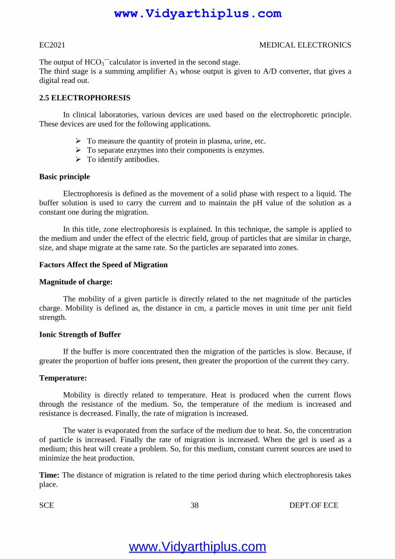
The sample for each test is placed on the strip at a marked location. Then, the constantelectric potential(250 V) is applied across the strip 4 – 6 mA of initial current is obtained .After15-20mins, the electric voltage is removed, then, migrated protein band is stained with bufferand it is dried in preparation for densitometry.
Figure 2.5 Pattern
The membrane is placed in the holder of densitometer. The path of the migration ofone of the specimen is scanned. The low voltage output is amplified and recorded using x-yrecorder.
Figure2.6 Cellulose acetate electrophoresis
www.Vidyarthiplus.com
www.Vidyarthiplus.com
EC2021 MEDICAL ELECTRONICS
SCE 40 DEPT.OF ECE
2.6 COLORIMETER
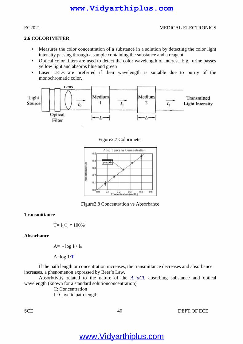
Measures the color concentration of a substance in a solution by detecting the color lightintensity passing through a sample containing the substance and a reagent
Optical color filters are used to detect the color wavelength of interest. E.g., urine passesyellow light and absorbs blue and green
Laser LEDs are preferred if their wavelength is suitable due to purity of themonochromatic color.
Figure2.7 Colorimeter
Figure2.8 Concentration vs Absorbance
Transmittance
T= I1/I0 * 100%
Absorbance
A= - log I1/ I0
A=log 1/T
If the path length or concentration increases, the transmittance decreases and absorbanceincreases, a phenomenon expressed by Beer’s Law.
Absorbtivity related to the nature of the A=aCL absorbing substance and opticalwavelength (known for a standard solutionconcentration).
C: ConcentrationL: Cuvette path length
EC2021 MEDICAL ELECTRONICS
SCE 40 DEPT.OF ECE
2.6 COLORIMETER
Measures the color concentration of a substance in a solution by detecting the color lightintensity passing through a sample containing the substance and a reagent
Optical color filters are used to detect the color wavelength of interest. E.g., urine passesyellow light and absorbs blue and green
Laser LEDs are preferred if their wavelength is suitable due to purity of themonochromatic color.
Figure2.7 Colorimeter
Figure2.8 Concentration vs Absorbance
Transmittance
T= I1/I0 * 100%
Absorbance
A= - log I1/ I0
A=log 1/T
If the path length or concentration increases, the transmittance decreases and absorbanceincreases, a phenomenon expressed by Beer’s Law.
Absorbtivity related to the nature of the A=aCL absorbing substance and opticalwavelength (known for a standard solutionconcentration).
C: ConcentrationL: Cuvette path length
www.Vidyarthiplus.com
www.Vidyarthiplus.com

EC2021 MEDICAL ELECTRONICS
SCE 41 DEPT.OF ECE
2.7 PHOTOMETER
2.7.1 FLAME PHOTOMETER
Figure2.9 Flame Photometer
Measures the color intensity of a flame supported by O2 and a specific substance.Sample’s emission of light is measured (rather than the absorbance of light).Typically used todetermine the conc. of pure metals and/or Na+, K+, Li+ and Ca++
In this method, fine droplets of the sample is aspirated into gas flame that burns in achimney. A known amount of lithium salt is added to the sample, as a reference. As a result, redlight is emitted by the lithium and yellow and violet beam are emitted due to sodium andpotassium respectively. These diffracted colours are made to incident on photodiodes. The photodetector circuits consists of a reverse biased diode in which the current flow increases as intensityof incident light increases. A calibration potentiometer is used in every channel. Since the lithiumis used as a standard reference, the output of sodium and potassium channel are calibrated interms of differences with the known lithium. The output can be compared with the spectralillustration.
2.7.2 SPECTROPHOTOMETER
The general name given to the group of instruments whose principle of operation isbased on the fact that substances of clinical interest selectively absorb or emit EMenergy (light) at different wavelengths.
www.Vidyarthiplus.com
www.Vidyarthiplus.com
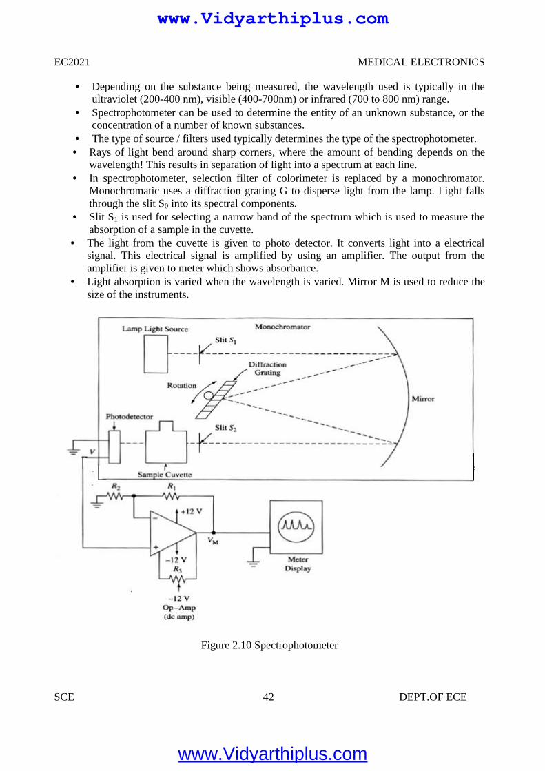
EC2021 MEDICAL ELECTRONICS
SCE 42 DEPT.OF ECE
Depending on the substance being measured, the wavelength used is typically in theultraviolet (200-400 nm), visible (400-700nm) or infrared (700 to 800 nm) range.
Spectrophotometer can be used to determine the entity of an unknown substance, or theconcentration of a number of known substances.
The type of source / filters used typically determines the type of the spectrophotometer. Rays of light bend around sharp corners, where the amount of bending depends on the
wavelength! This results in separation of light into a spectrum at each line. In spectrophotometer, selection filter of colorimeter is replaced by a monochromator.
Monochromatic uses a diffraction grating G to disperse light from the lamp. Light fallsthrough the slit S0 into its spectral components.
Slit S1 is used for selecting a narrow band of the spectrum which is used to measure theabsorption of a sample in the cuvette.
The light from the cuvette is given to photo detector. It converts light into a electricalsignal. This electrical signal is amplified by using an amplifier. The output from theamplifier is given to meter which shows absorbance.
Light absorption is varied when the wavelength is varied. Mirror M is used to reduce thesize of the instruments.
Figure 2.10 Spectrophotometer
www.Vidyarthiplus.com
www.Vidyarthiplus.com
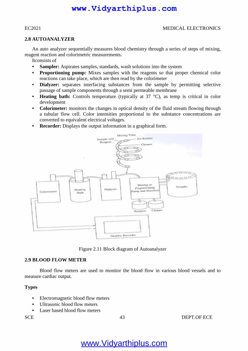
EC2021 MEDICAL ELECTRONICS
SCE 43 DEPT.OF ECE
2.8 AUTOANALYZER
An auto analyzer sequentially measures blood chemistry through a series of steps of mixing,reagent reaction and colorimetric measurements.
Itconsists of Sampler: Aspirates samples, standards, wash solutions into the system Proportioning pump: Mixes samples with the reagents so that proper chemical color
reactions can take place, which are then read by the colorimeter Dialyzer: separates interfacing substances from the sample by permitting selective
passage of sample components through a semi permeable membrane Heating bath: Controls temperature (typically at 37 °C), as temp is critical in color
development Colorimeter: monitors the changes in optical density of the fluid stream flowing through
a tubular flow cell. Color intensities proportional to the substance concentrations areconverted to equivalent electrical voltages.
Recorder: Displays the output information in a graphical form.
Figure 2.11 Block diagram of Autoanalyzer
2.9 BLOOD FLOW METER
Blood flow meters are used to monitor the blood flow in various blood vessels and tomeasure cardiac output.
Types
Electromagnetic blood flow meters Ultrasonic blood flow meters Laser based blood flow meters
www.Vidyarthiplus.com
www.Vidyarthiplus.com
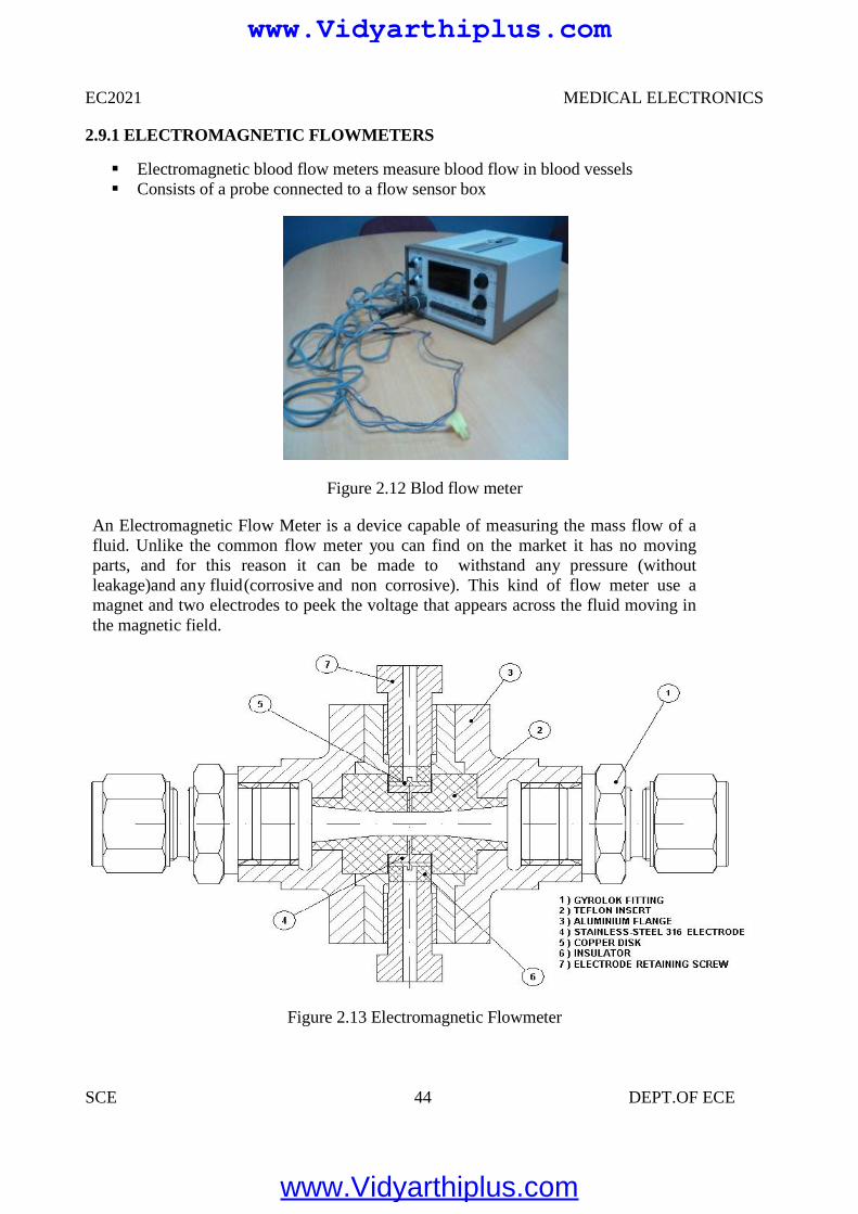
EC2021 MEDICAL ELECTRONICS
SCE 44 DEPT.OF ECE
2.9.1 ELECTROMAGNETIC FLOWMETERS
Electromagnetic blood flow meters measure blood flow in blood vessels Consists of a probe connected to a flow sensor box
Figure 2.12 Blod flow meter
An Electromagnetic Flow Meter is a device capable of measuring the mass flow of afluid. Unlike the common flow meter you can find on the market it has no movingparts, and for this reason it can be made to withstand any pressure (withoutleakage)and any fluid(corrosive and non corrosive). This kind of flow meter use amagnet and two electrodes to peek the voltage that appears across the fluid moving inthe magnetic field.
Figure 2.13 Electromagnetic Flowmeter
www.Vidyarthiplus.com
www.Vidyarthiplus.com
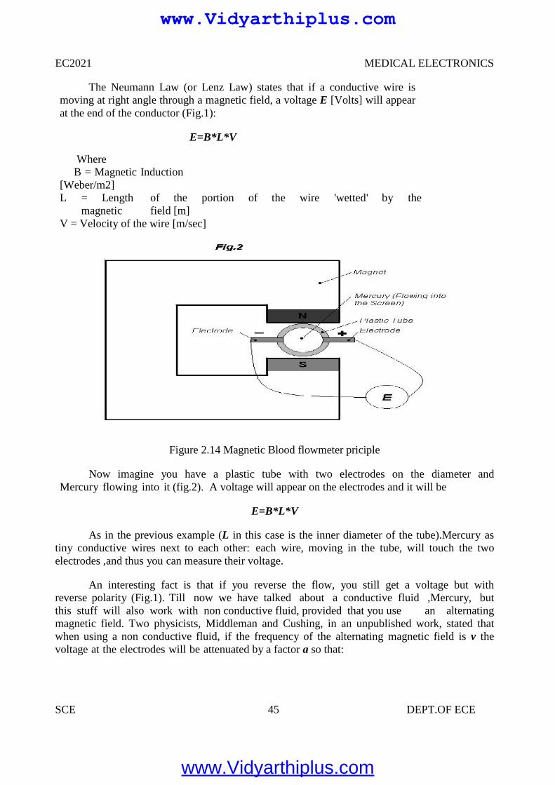
EC2021 MEDICAL ELECTRONICS
SCE 45 DEPT.OF ECE
The Neumann Law (or Lenz Law) states that if a conductive wire ismoving at right angle through a magnetic field, a voltage E [Volts] will appearat the end of the conductor (Fig.1):
E=B*L*V
WhereB = Magnetic Induction
[Weber/m2]L = Length of the portion of the wire 'wetted' by the
magnetic field [m]V = Velocity of the wire [m/sec]
Figure 2.14 Magnetic Blood flowmeter priciple
Now imagine you have a plastic tube with two electrodes on the diameter andMercury flowing into it (fig.2). A voltage will appear on the electrodes and it will be
E=B*L*V
As in the previous example (L in this case is the inner diameter of the tube).Mercury astiny conductive wires next to each other: each wire, moving in the tube, will touch the twoelectrodes ,and thus you can measure their voltage.
An interesting fact is that if you reverse the flow, you still get a voltage but withreverse polarity (Fig.1). Till now we have talked about a conductive fluid ,Mercury, butthis stuff will also work with non conductive fluid, provided that you use an alternatingmagnetic field. Two physicists, Middleman and Cushing, in an unpublished work, stated thatwhen using a non conductive fluid, if the frequency of the alternating magnetic field is v thevoltage at the electrodes will be attenuated by a factor a so that:
www.Vidyarthiplus.com
www.Vidyarthiplus.com
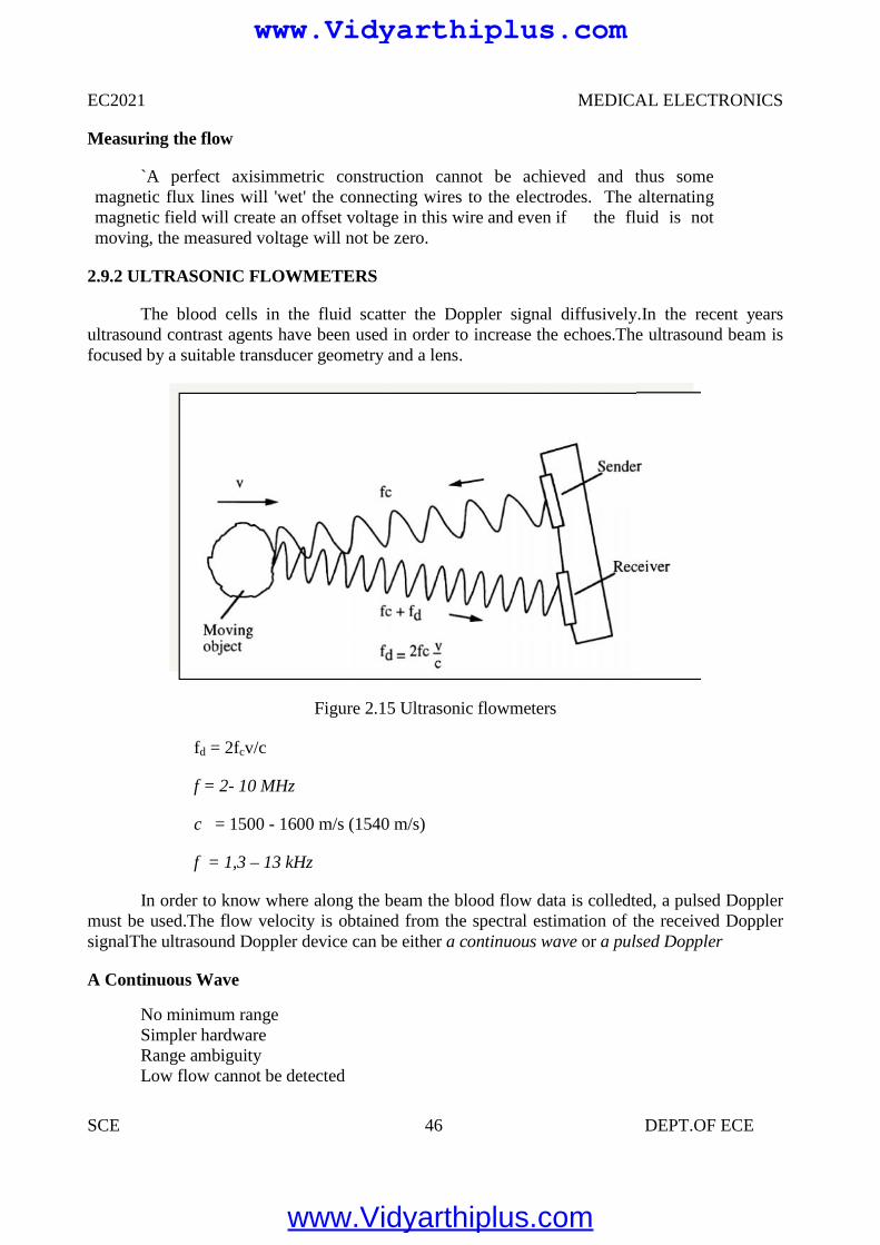
EC2021 MEDICAL ELECTRONICS
SCE 46 DEPT.OF ECE
Measuring the flow
`A perfect axisimmetric construction cannot be achieved and thus somemagnetic flux lines will 'wet' the connecting wires to the electrodes. The alternatingmagnetic field will create an offset voltage in this wire and even if the fluid is notmoving, the measured voltage will not be zero.
2.9.2 ULTRASONIC FLOWMETERS
The blood cells in the fluid scatter the Doppler signal diffusively.In the recent yearsultrasound contrast agents have been used in order to increase the echoes.The ultrasound beam isfocused by a suitable transducer geometry and a lens.
Figure 2.15 Ultrasonic flowmeters
fd = 2fcv/c
f = 2- 10 MHz
c = 1500 - 1600 m/s (1540 m/s)
f = 1,3 – 13 kHz
In order to know where along the beam the blood flow data is colledted, a pulsed Dopplermust be used.The flow velocity is obtained from the spectral estimation of the received DopplersignalThe ultrasound Doppler device can be either a continuous wave or a pulsed Doppler
A Continuous Wave
No minimum rangeSimpler hardwareRange ambiguityLow flow cannot be detected
www.Vidyarthiplus.com
www.Vidyarthiplus.com
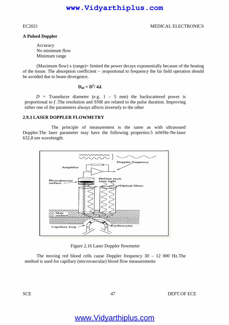
EC2021 MEDICAL ELECTRONICS
SCE 47 DEPT.OF ECE
A Pulsed Doppler
AccuracyNo minimum flowMinimum range
(Maximum flow) x (range)= limited the power decays exponentially because of the heatingof the tissue. The absorption coefficient ~ proportional to frequency the far field operation shouldbe avoided due to beam divergence.
Dnf = D2/ 4
D = Transducer diameter (e.g. 1 – 5 mm) the backscattered power isproportional to f .The resolution and SNR are related to the pulse duration. Improvingeither one of the parameters always affects inversely to the other
2.9.3 LASER DOPPLER FLOWMETRY
The principle of measurement is the same as with ultrasoundDoppler.The laser parameter may have the following properties:5 mWHe-Ne-laser632,8 nm wavelength.
Figure 2.16 Laser Doppler flowmeter
The moving red blood cells cause Doppler frequency 30 – 12 000 Hz.Themethod is used for capillary (microvascular) blood flow measurements
www.Vidyarthiplus.com
www.Vidyarthiplus.com
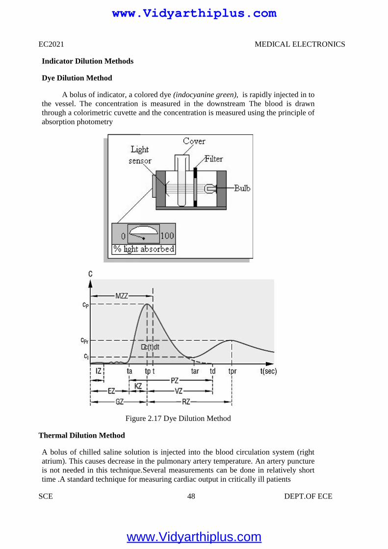
EC2021 MEDICAL ELECTRONICS
SCE 48 DEPT.OF ECE
Indicator Dilution Methods
Dye Dilution Method
A bolus of indicator, a colored dye (indocyanine green), is rapidly injected in tothe vessel. The concentration is measured in the downstream The blood is drawnthrough a colorimetric cuvette and the concentration is measured using the principle ofabsorption photometry
Figure 2.17 Dye Dilution Method
Thermal Dilution Method
A bolus of chilled saline solution is injected into the blood circulation system (rightatrium). This causes decrease in the pulmonary artery temperature. An artery punctureis not needed in this technique.Several measurements can be done in relatively shorttime .A standard technique for measuring cardiac output in critically ill patients
www.Vidyarthiplus.com
www.Vidyarthiplus.com
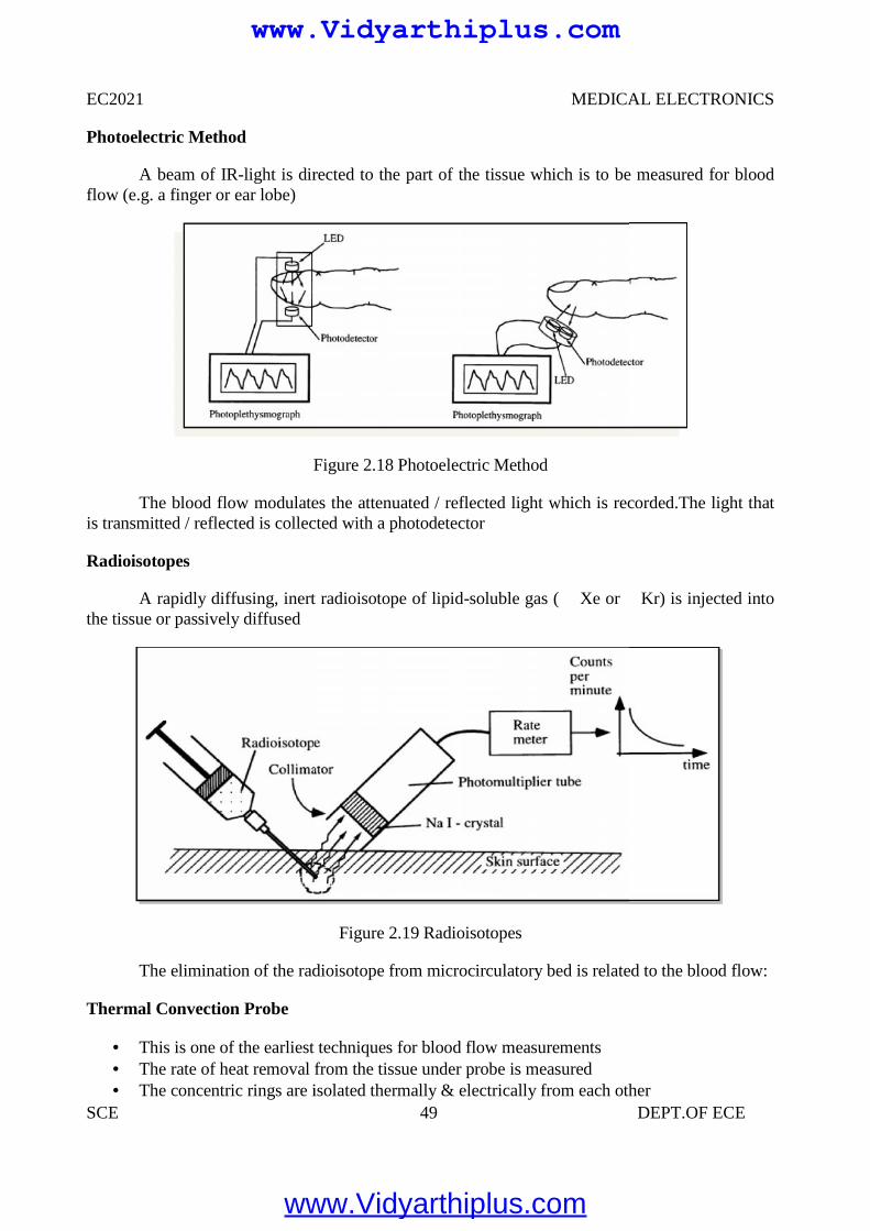
EC2021 MEDICAL ELECTRONICS
SCE 49 DEPT.OF ECE
Photoelectric Method
A beam of IR-light is directed to the part of the tissue which is to be measured for bloodflow (e.g. a finger or ear lobe)
Figure 2.18 Photoelectric Method
The blood flow modulates the attenuated / reflected light which is recorded.The light thatis transmitted / reflected is collected with a photodetector
Radioisotopes
A rapidly diffusing, inert radioisotope of lipid-soluble gas ( Xe or Kr) is injected intothe tissue or passively diffused
Figure 2.19 Radioisotopes
The elimination of the radioisotope from microcirculatory bed is related to the blood flow:
Thermal Convection Probe
This is one of the earliest techniques for blood flow measurements The rate of heat removal from the tissue under probe is measured The concentric rings are isolated thermally & electrically from each other
www.Vidyarthiplus.com
www.Vidyarthiplus.com
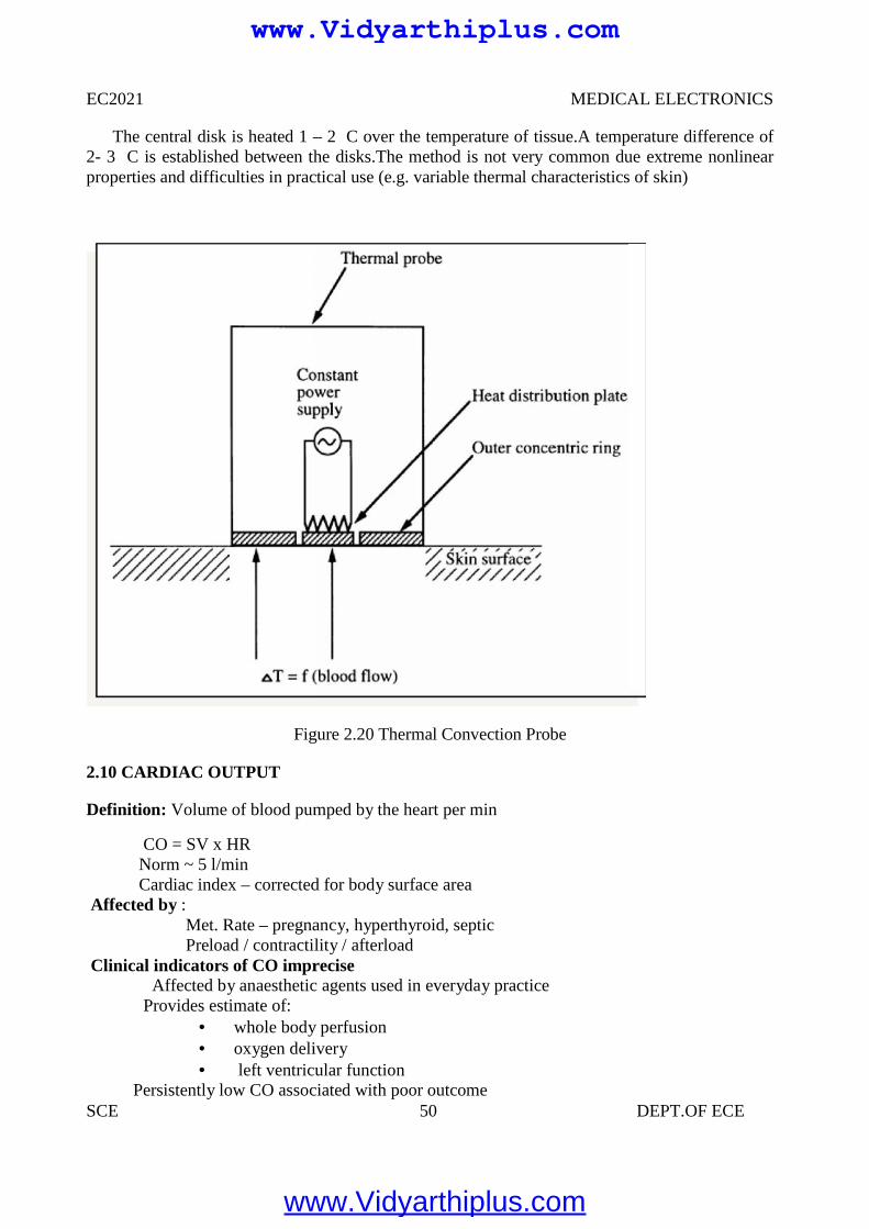
EC2021 MEDICAL ELECTRONICS
SCE 50 DEPT.OF ECE
The central disk is heated 1 – 2 C over the temperature of tissue.A temperature difference of2- 3 C is established between the disks.The method is not very common due extreme nonlinearproperties and difficulties in practical use (e.g. variable thermal characteristics of skin)
Figure 2.20 Thermal Convection Probe
2.10 CARDIAC OUTPUT
Definition: Volume of blood pumped by the heart per min
CO = SV x HRNorm ~ 5 l/minCardiac index – corrected for body surface area
Affected by :Met. Rate – pregnancy, hyperthyroid, septicPreload / contractility / afterload
Clinical indicators of CO impreciseAffected by anaesthetic agents used in everyday practice
Provides estimate of: whole body perfusion oxygen delivery left ventricular function
Persistently low CO associated with poor outcome
www.Vidyarthiplus.com
www.Vidyarthiplus.com
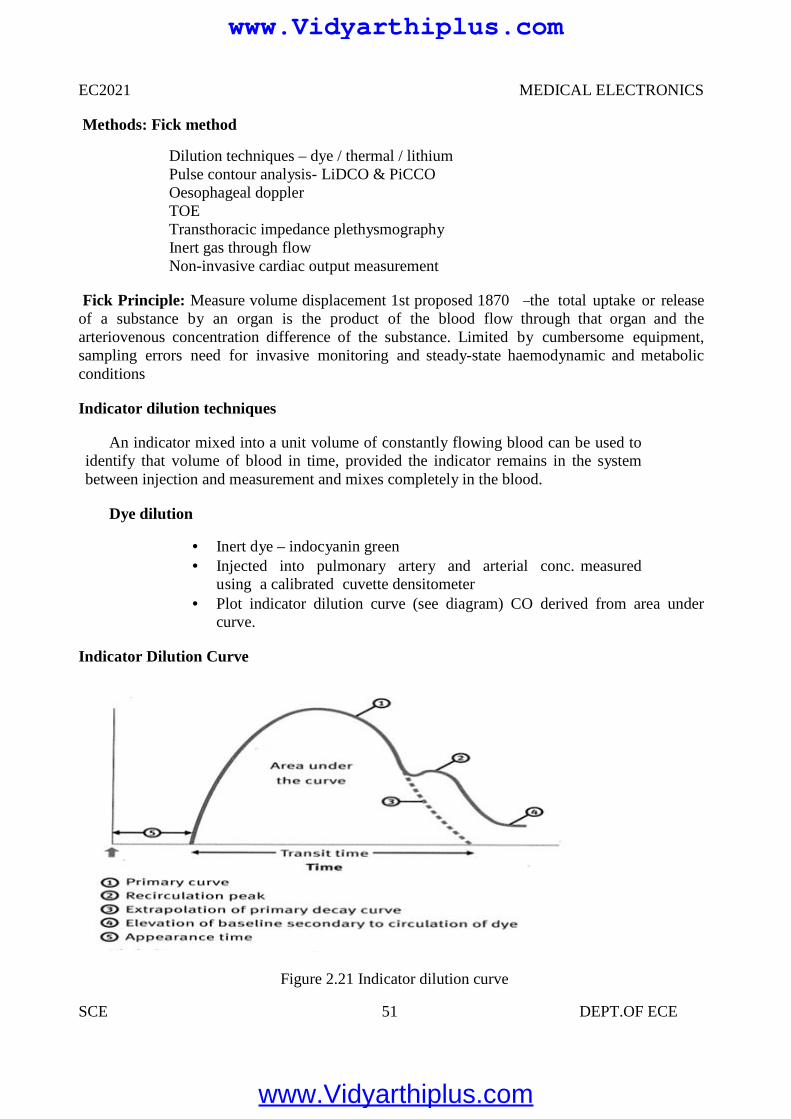
EC2021 MEDICAL ELECTRONICS
SCE 51 DEPT.OF ECE
Methods: Fick method
Dilution techniques – dye / thermal / lithiumPulse contour analysis- LiDCO & PiCCOOesophageal dopplerTOETransthoracic impedance plethysmographyInert gas through flowNon-invasive cardiac output measurement
Fick Principle: Measure volume displacement 1st proposed 1870 ―the total uptake or releaseof a substance by an organ is the product of the blood flow through that organ and thearteriovenous concentration difference of the substance. Limited by cumbersome equipment,sampling errors need for invasive monitoring and steady-state haemodynamic and metabolicconditions
Indicator dilution techniques
An indicator mixed into a unit volume of constantly flowing blood can be used toidentify that volume of blood in time, provided the indicator remains in the systembetween injection and measurement and mixes completely in the blood.
Dye dilution
Inert dye – indocyanin green Injected into pulmonary artery and arterial conc. measured
using a calibrated cuvette densitometer Plot indicator dilution curve (see diagram) CO derived from area under
curve.
Indicator Dilution Curve
Figure 2.21 Indicator dilution curve
www.Vidyarthiplus.com
www.Vidyarthiplus.com
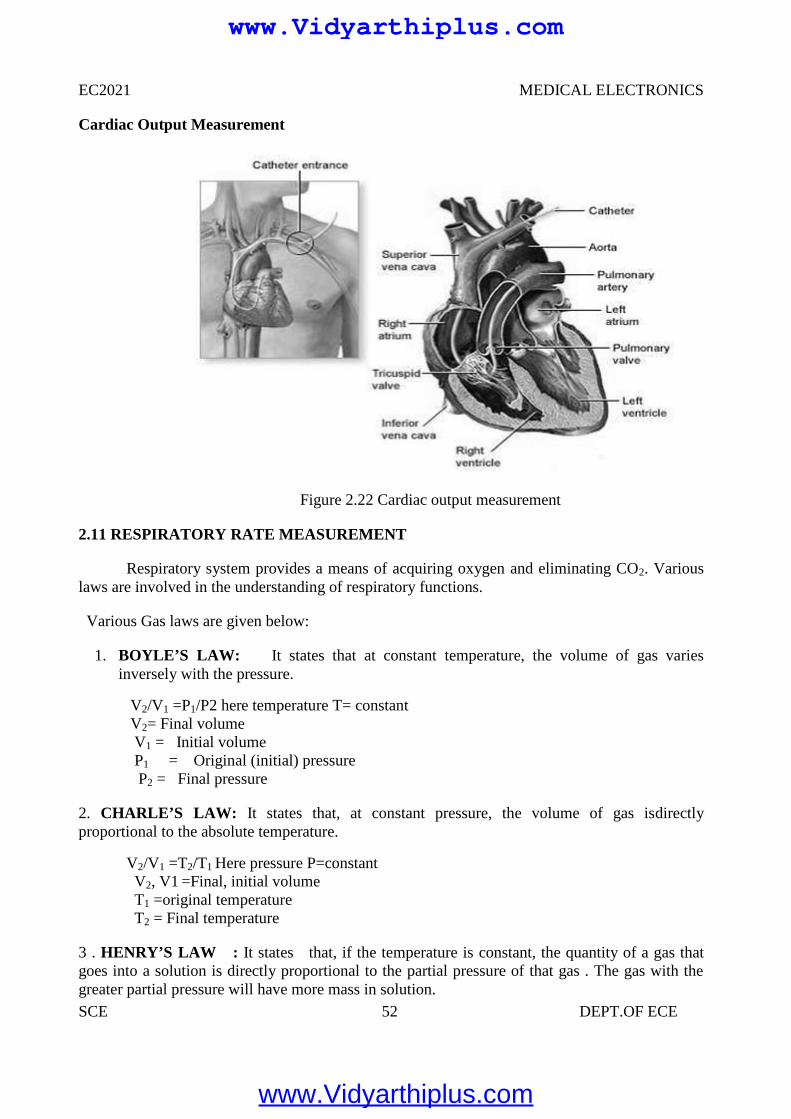
EC2021 MEDICAL ELECTRONICS
SCE 52 DEPT.OF ECE
Cardiac Output Measurement
Figure 2.22 Cardiac output measurement
2.11 RESPIRATORY RATE MEASUREMENT
Respiratory system provides a means of acquiring oxygen and eliminating CO2. Variouslaws are involved in the understanding of respiratory functions.
Various Gas laws are given below:
1. BOYLE’S LAW: It states that at constant temperature, the volume of gas variesinversely with the pressure.
V2/V1 =P1/P2 here temperature T= constantV2= Final volumeV1 = Initial volumeP1 = Original (initial) pressureP2 = Final pressure
2. CHARLE’S LAW: It states that, at constant pressure, the volume of gas isdirectlyproportional to the absolute temperature.
V2/V1 =T2/T1 Here pressure P=constantV2, V1 =Final, initial volumeT1 =original temperatureT2 = Final temperature
3 . HENRY’S LAW : It states that, if the temperature is constant, the quantity of a gas thatgoes into a solution is directly proportional to the partial pressure of that gas . The gas with thegreater partial pressure will have more mass in solution.
www.Vidyarthiplus.com
www.Vidyarthiplus.com
EC2021 MEDICAL ELECTRONICS
SCE 53 DEPT.OF ECE
4. DALTON’S LAW : It states that, the total pressure exerted by a mixture of gases is equal tothe sum of the partial pressures of various gases.
PT =P1 + P2 + …………… +Pn
PT = total pressureP1, P2 ,P3 = partial pressure of various gases
TYPES OF RESPIRATION
Types of respiration
Internal respiration External respiration
Respiration is nothing but the interchange of gases between an organism and the living mediumInternal respiration is the exchange of gases between the blood stream and nearby cells.External respiration is the exchange of gases between the lungs and blood stream .
Lungs Volumes and Capacities (Respiration Parameters) Or (LVC)
Respiration parameters are used to indicate the state of respiratory function , including lungvolumes and capacities , airway resistance , lung compliance , etc .
Dead Air
Only a portion of the air entering the respiratory system actually reaches the alveoli . Thevolume of air that is not available for gas exchange with the blood is known as dead air . Thetotal dead space is less less than 30 percentage of the total volume .
Tidal Volume (TV)
Tidal volume is the depth of breathing or the volume of gas inspired or expired during eachrespiratory cycle. It is equal to 500 ml for a normal person .
Inspiratory Reserve Volume (IRV)
It is the maximal amount of gas that can be inspired from the end- inspiratory position (Extra inspiration from the high peak tidal volume . It is equal to 3600 ml for a normal person
Expiratory reserve volume (ERV)
It is the maximal amount of gas that can be end expiratory level. It is equal to 1200 ml.
Residual Volume(RV)
It is the amount of gas remaining in the lungs at the end of maximal expiration. It is equalto 1200 ml.
www.Vidyarthiplus.com
www.Vidyarthiplus.com
EC2021 MEDICAL ELECTRONICS
SCE 54 DEPT.OF ECE
Minute Volume (MV)It is the volume of air breathed normally for 1 minute.Total Lung Capacity(TLC)
It is the amount of gas contained in the lungs at the end of maximal inspiration and it isthe sum of inspiratory capacity(IC) and functional residual capacity (FRC). TLC is of 6000 mlfor a normal person.Vital Capacity(VC)
It is the maximum amount of gas that can be expelled from the lungs by forceful effortfrom maximal inspiration. It is 4800 ml for a normal person.Inspiratory Capacity(IC)
It is the maximum amount of gas that can be inspired from the resting expiratory level andit is the sum of tidal volume and inspiratory reserve volume. It is equal to 3600 ml for a normalperson.Functional Residual Capacity(FRC)
It is the amount of gas remaining in the lungs at the resting expiratory level.FRC = ERV + RV
Airway resistanceIt relates to the ease with air flows through tubular respiratory structures. In smaller tubes,
airway resistance is high.Lung Compliance
It is the ability of the alveoli and lung tissue to expand on inspiration.Lung Elasticity
It is the ability of the lung’s elastic tissues to recoil during expirationIntra thoractic Pressure
It is the positive and negative pressure occur within the thoracic cavityTypes of respiration rate measurement
1. Displacement method2. Thermistor method3. Impedance pneumography4. CO2 method5. Apnoea detectors
Displacement Method
In this method the transducer is hold by an elastic band which goes around the chest.Therespiratory movements results in a corresponding resistance changes of the strain gauge. It isconnected as one arm of a wheatstone bridge circuit. Its output varies with chest expansion. Thisoutput corresponds to the respiration activity.
Thermistor Method
Generally there is a temperature difference between inspired and expired air. This temperature issensed by placing thermistor in front of nostrils. Thermistor is placed by using suitable stand. Thethermistor is connected with the bridge circuit. So unbalance signal is amplified to get therespiratory activity.
www.Vidyarthiplus.com
www.Vidyarthiplus.com
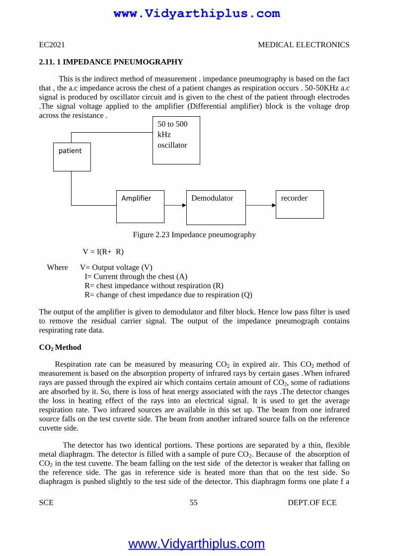
EC2021 MEDICAL ELECTRONICS
SCE 55 DEPT.OF ECE
2.11. 1 IMPEDANCE PNEUMOGRAPHY
This is the indirect method of measurement . impedance pneumography is based on the factthat , the a.c impedance across the chest of a patient changes as respiration occurs . 50-50KHz a.csignal is produced by oscillator circuit and is given to the chest of the patient through electrodes.The signal voltage applied to the amplifier (Differential amplifier) block is the voltage dropacross the resistance .
Figure 2.23 Impedance pneumography
V = I(R+ R)
Where V= Output voltage (V)I= Current through the chest (A)R= chest impedance without respiration (R)R= change of chest impedance due to respiration (Q)
The output of the amplifier is given to demodulator and filter block. Hence low pass filter is usedto remove the residual carrier signal. The output of the impedance pneumograph containsrespirating rate data.
CO2 Method
Respiration rate can be measured by measuring CO2 in expired air. This CO2 method ofmeasurement is based on the absorption property of infrared rays by certain gases .When infraredrays are passed through the expired air which contains certain amount of CO2, some of radiationsare absorbed by it. So, there is loss of heat energy associated with the rays .The detector changesthe loss in heating effect of the rays into an electrical signal. It is used to get the averagerespiration rate. Two infrared sources are available in this set up. The beam from one infraredsource falls on the test cuvette side. The beam from another infrared source falls on the referencecuvette side.
The detector has two identical portions. These portions are separated by a thin, flexiblemetal diaphragm. The detector is filled with a sample of pure CO2. Because of the absorption ofCO2 in the test cuvette. The beam falling on the test side of the detector is weaker that falling onthe reference side. The gas in reference side is heated more than that on the test side. Sodiaphragm is pushed slightly to the test side of the detector. This diaphragm forms one plate f a
patient
50 to 500kHzoscillator
Demodulator recorderAmplifier
www.Vidyarthiplus.com
www.Vidyarthiplus.com
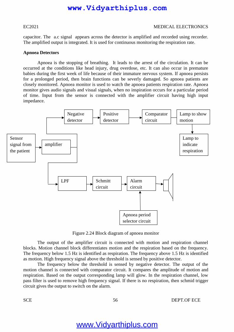
EC2021 MEDICAL ELECTRONICS
SCE 56 DEPT.OF ECE
capacitor. The a.c signal appears across the detector is amplified and recorded using recorder.The amplified output is integrated. It is used for continuous monitoring the respiration rate.
Apnoea Detectors
Apnoea is the stopping of breathing. It leads to the arrest of the circulation. It can beoccurred at the conditions like head injury, drug overdose, etc. It can also occur in prematurebabies during the first week of life because of their immature nervous system. If apnoea persistsfor a prolonged period, then brain functions can be severly damaged. So apnoea patients areclosely monitored. Apnoea monitor is used to watch the apnoea patients respiration rate. Apnoeamonitor gives audio signals and visual signals, when no inspiration occurs for a particular periodof time. Input from the sensor is connected with the amplifier circuit having high inputimpedance.
Figure 2.24 Block diagram of apnoea monitor
The output of the amplifier circuit is connected with motion and respiration channelblocks. Motion channel block differentiates motion and the respiration based on the frequency.The frequency below 1.5 Hz is identified as respiration. The frequency above 1.5 Hz is identifiedas motion. High frequency signal above the threshold is sensed by positive detector.
The frequency below the threshold is sensed by negative detector. The output of themotion channel is connected with comparator circuit. It compares the amplitude of motion andrespiration. Based on the output corresponding lamp will glow. In the respiration channel, lowpass filter is used to remove high frequency signal. If there is no respiration, then schmid triggercircuit gives the output to switch on the alarm.
Sensorsignal fromthe patient
Negativedetector
amplifier
Positivedetector
Comparatorcircuit
Lamp toindicaterespiration
Lamp to showmotion
LPF Schmittcircuit
Alarmcircuit
Apnoea periodselector circuit
www.Vidyarthiplus.com
www.Vidyarthiplus.com
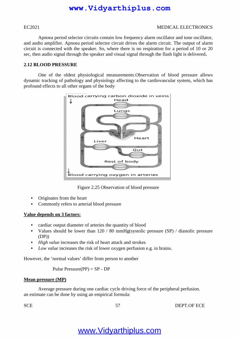
EC2021 MEDICAL ELECTRONICS
SCE 57 DEPT.OF ECE
Apnoea period selector circuits contain low frequency alarm oscillator and tone oscillator,and audio amplifier. Apnoea period selector circuit drives the alarm circuit. The output of alarmcircuit is connected with the speaker. So, where there is no respiration for a period of 10 or 20sec, then audio signal through the speaker and visual signal through the flash light is delivered.
2.12 BLOOD PRESSURE
One of the oldest physiological measurements.Observation of blood pressure allowsdynamic tracking of pathology and physiology affecting to the cardiovascular system, which hasprofound effects to all other organs of the body
Figure 2.25 Observation of blood pressure
Originates from the heart Commonly refers to arterial blood pressure
Value depends on 3 factors:
cardiac output diameter of arteries the quantity of blood Values should be lower than 120 / 80 mmHg(systolic pressure (SP) / diastolic pressure
(DP)) High value increases the risk of heart attack and strokes Low value increases the risk of lower oxygen perfusion e.g. in brains.
However, the ’normal values’ differ from person to another
Pulse Pressure(PP) = SP - DP
Mean pressure (MP)
Average pressure during one cardiac cycle driving force of the peripheral perfusion.an estimate can be done by using an empirical formula:
www.Vidyarthiplus.com
www.Vidyarthiplus.com
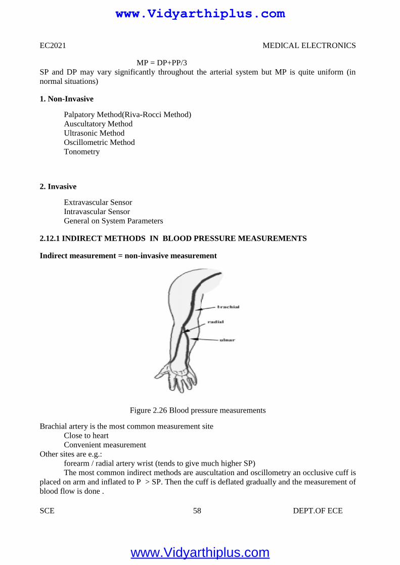
EC2021 MEDICAL ELECTRONICS
SCE 58 DEPT.OF ECE
MP = DP+PP/3SP and DP may vary significantly throughout the arterial system but MP is quite uniform (innormal situations)
1. Non-Invasive
Palpatory Method(Riva-Rocci Method)Auscultatory MethodUltrasonic MethodOscillometric MethodTonometry
2. Invasive
Extravascular SensorIntravascular SensorGeneral on System Parameters
2.12.1 INDIRECT METHODS IN BLOOD PRESSURE MEASUREMENTS
Indirect measurement = non-invasive measurement
Figure 2.26 Blood pressure measurements
Brachial artery is the most common measurement siteClose to heartConvenient measurement
Other sites are e.g.:forearm / radial artery wrist (tends to give much higher SP)The most common indirect methods are auscultation and oscillometry an occlusive cuff is
placed on arm and inflated to P > SP. Then the cuff is deflated gradually and the measurement ofblood flow is done .
www.Vidyarthiplus.com
www.Vidyarthiplus.com
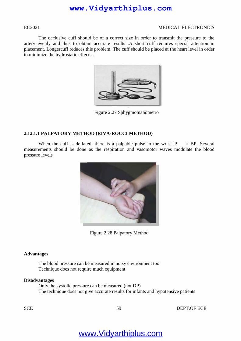
EC2021 MEDICAL ELECTRONICS
SCE 59 DEPT.OF ECE
The occlusive cuff should be of a correct size in order to transmit the pressure to theartery evenly and thus to obtain accurate results .A short cuff requires special attention inplacement. Longercuff reduces this problem. The cuff should be placed at the heart level in orderto minimize the hydrostatic effects .
Figure 2.27 Sphygmomanometro
2.12.1.1 PALPATORY METHOD (RIVA-ROCCI METHOD)
When the cuff is deflated, there is a palpable pulse in the wrist. P = BP .Severalmeasurements should be done as the respiration and vasomotor waves modulate the bloodpressure levels
Figure 2.28 Palpatory Method
Advantages
The blood pressure can be measured in noisy environment tooTechnique does not require much equipment
DisadvantagesOnly the systolic pressure can be measured (not DP)The technique does not give accurate results for infants and hypotensive patients
www.Vidyarthiplus.com
www.Vidyarthiplus.com
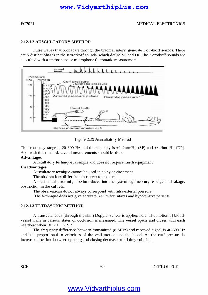
EC2021 MEDICAL ELECTRONICS
SCE 60 DEPT.OF ECE
2.12.1.2 AUSCULTATORY METHOD
Pulse waves that propagate through the brachial artery, generate Korotkoff sounds. Thereare 5 distinct phases in the Korotkoff sounds, which define SP and DP The Korotkoff sounds areausculted with a stethoscope or microphone (automatic measurement
Figure 2.29 Auscultatory Method
The frequency range is 20-300 Hz and the accuracy is +/- 2mmHg (SP) and +/- 4mmHg (DP).Also with this method, several measurements should be done.Advantages
Auscultatory technique is simple and does not require much equipmentDisadvantages
Auscultatory tecnique cannot be used in noisy environmentThe observations differ from observer to anotherA mechanical error might be introduced into the system e.g. mercury leakage, air leakage,
obstruction in the cuff etc.The observations do not always correspond with intra-arterial pressureThe technique does not give accurate results for infants and hypotensive patients
2.12.1.3 ULTRASONIC METHOD
A transcutaneous (through the skin) Doppler sensor is applied here. The motion of blood-vessel walls in various states of occlusion is measured. The vessel opens and closes with eachheartbeat when DP < P < SP .
The frequency difference between transmitted (8 MHz) and received signal is 40-500 Hzand it is proportional to velocities of the wall motion and the blood. As the cuff pressure isincreased, the time between opening and closing decreases until they coincide.
www.Vidyarthiplus.com
www.Vidyarthiplus.com
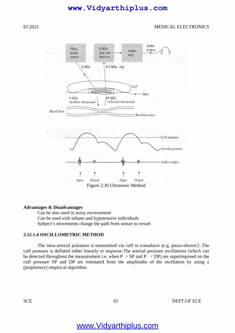
EC2021 MEDICAL ELECTRONICS
SCE 61 DEPT.OF ECE
Figure 2.30 Ultrasonic Method
Advantages & DisadvantagesCan be also used in noisy environmentCan be used with infants and hypotensive individualsSubject’s movements change the path from sensor to vessel
2.12.1.4 OSCILLOMETRIC METHOD
The intra-arterial pulsation is transmitted via cuff to transducer (e.g. piezo-electric) .Thecuff pressure is deflated either linearly or stepwise.The arterial pressure oscillations (which canbe detected throughout the measurement i.e. when P > SP and P < DP) are superimposed on thecuff pressure SP and DP are estimated from the amplitudes of the oscillation by using a(proprietary) empirical algorithm.
www.Vidyarthiplus.com
www.Vidyarthiplus.com
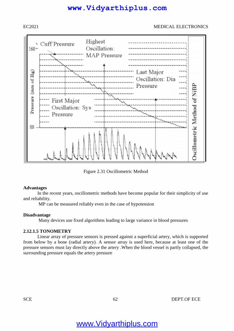
EC2021 MEDICAL ELECTRONICS
SCE 62 DEPT.OF ECE
Figure 2.31 Oscillometric Method
AdvantagesIn the recent years, oscillometric methods have become popular for their simplicity of use
and reliability.MP can be measured reliably even in the case of hypotension
DisadvantageMany devices use fixed algorithms leading to large variance in blood pressures
2.12.1.5 TONOMETRYLinear array of pressure sensors is pressed against a superficial artery, which is supported
from below by a bone (radial artery). A sensor array is used here, because at least one of thepressure sensors must lay directly above the artery .When the blood vessel is partly collapsed, thesurrounding pressure equals the artery pressure
www.Vidyarthiplus.com
www.Vidyarthiplus.com
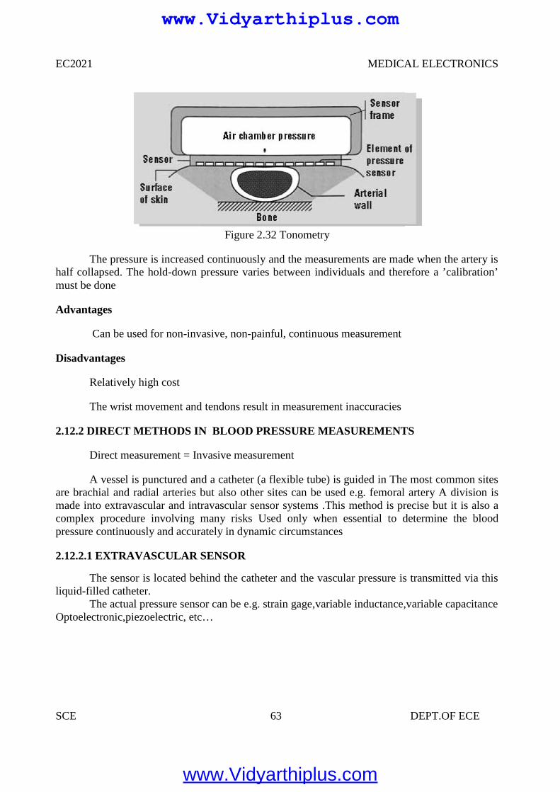
EC2021 MEDICAL ELECTRONICS
SCE 63 DEPT.OF ECE
Figure 2.32 Tonometry
The pressure is increased continuously and the measurements are made when the artery ishalf collapsed. The hold-down pressure varies between individuals and therefore a ’calibration’must be done
Advantages
Can be used for non-invasive, non-painful, continuous measurement
Disadvantages
Relatively high cost
The wrist movement and tendons result in measurement inaccuracies
2.12.2 DIRECT METHODS IN BLOOD PRESSURE MEASUREMENTS
Direct measurement = Invasive measurement
A vessel is punctured and a catheter (a flexible tube) is guided in The most common sitesare brachial and radial arteries but also other sites can be used e.g. femoral artery A division ismade into extravascular and intravascular sensor systems .This method is precise but it is also acomplex procedure involving many risks Used only when essential to determine the bloodpressure continuously and accurately in dynamic circumstances
2.12.2.1 EXTRAVASCULAR SENSOR
The sensor is located behind the catheter and the vascular pressure is transmitted via thisliquid-filled catheter.
The actual pressure sensor can be e.g. strain gage,variable inductance,variable capacitanceOptoelectronic,piezoelectric, etc…
www.Vidyarthiplus.com
www.Vidyarthiplus.com
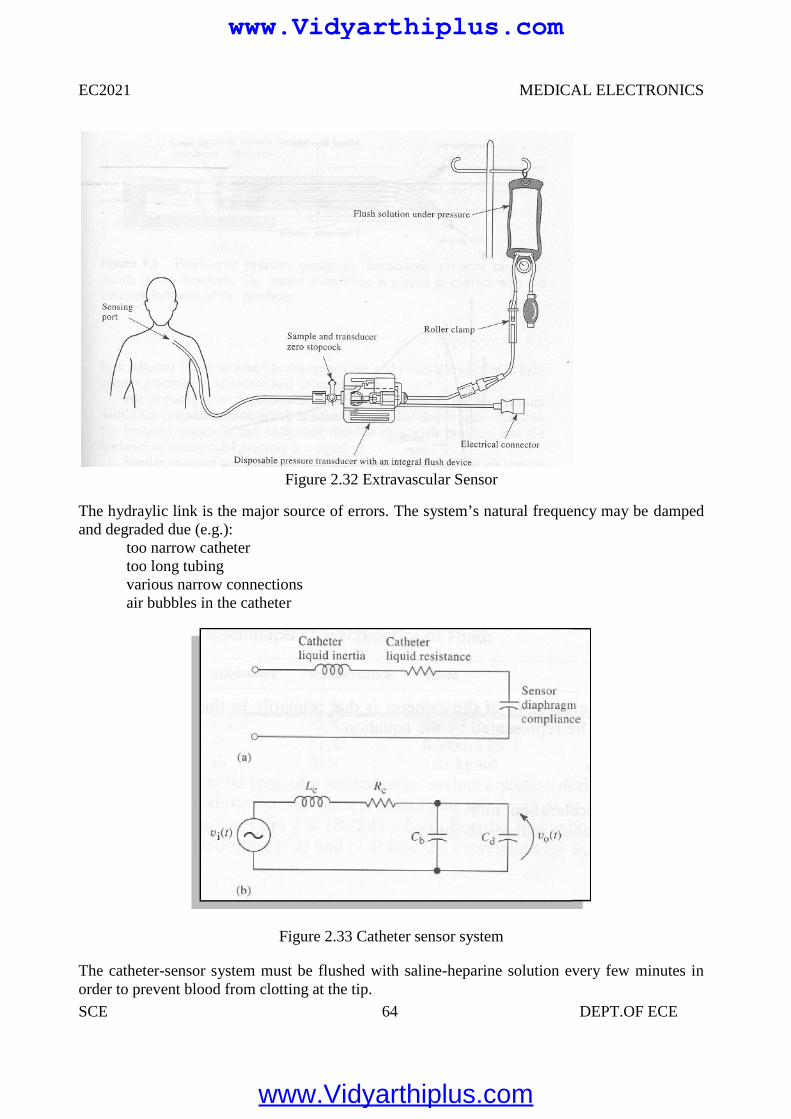
EC2021 MEDICAL ELECTRONICS
SCE 64 DEPT.OF ECE
Figure 2.32 Extravascular Sensor
The hydraylic link is the major source of errors. The system’s natural frequency may be dampedand degraded due (e.g.):
too narrow cathetertoo long tubingvarious narrow connectionsair bubbles in the catheter
Figure 2.33 Catheter sensor system
The catheter-sensor system must be flushed with saline-heparine solution every few minutes inorder to prevent blood from clotting at the tip.
www.Vidyarthiplus.com
www.Vidyarthiplus.com
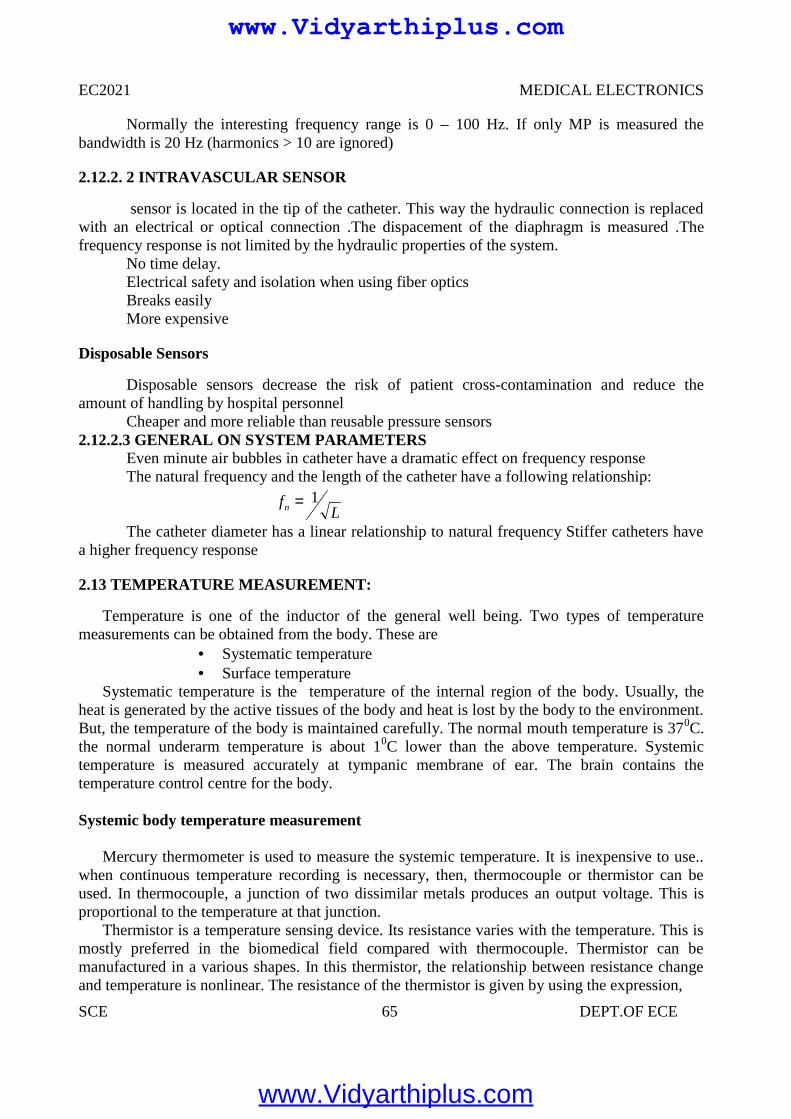
EC2021 MEDICAL ELECTRONICS
SCE 65 DEPT.OF ECE
Normally the interesting frequency range is 0 – 100 Hz. If only MP is measured thebandwidth is 20 Hz (harmonics > 10 are ignored)
2.12.2. 2 INTRAVASCULAR SENSOR
sensor is located in the tip of the catheter. This way the hydraulic connection is replacedwith an electrical or optical connection .The dispacement of the diaphragm is measured .Thefrequency response is not limited by the hydraulic properties of the system.
No time delay.Electrical safety and isolation when using fiber opticsBreaks easilyMore expensive
Disposable Sensors
Disposable sensors decrease the risk of patient cross-contamination and reduce theamount of handling by hospital personnel
Cheaper and more reliable than reusable pressure sensors2.12.2.3 GENERAL ON SYSTEM PARAMETERS
Even minute air bubbles in catheter have a dramatic effect on frequency responseThe natural frequency and the length of the catheter have a following relationship:
The catheter diameter has a linear relationship to natural frequency Stiffer catheters havea higher frequency response
2.13 TEMPERATURE MEASUREMENT:
Temperature is one of the inductor of the general well being. Two types of temperaturemeasurements can be obtained from the body. These are
Systematic temperature Surface temperature
Systematic temperature is the temperature of the internal region of the body. Usually, theheat is generated by the active tissues of the body and heat is lost by the body to the environment.But, the temperature of the body is maintained carefully. The normal mouth temperature is 370C.the normal underarm temperature is about 10C lower than the above temperature. Systemictemperature is measured accurately at tympanic membrane of ear. The brain contains thetemperature control centre for the body.
Systemic body temperature measurement
Mercury thermometer is used to measure the systemic temperature. It is inexpensive to use..when continuous temperature recording is necessary, then, thermocouple or thermistor can beused. In thermocouple, a junction of two dissimilar metals produces an output voltage. This isproportional to the temperature at that junction.
Thermistor is a temperature sensing device. Its resistance varies with the temperature. This ismostly preferred in the biomedical field compared with thermocouple. Thermistor can bemanufactured in a various shapes. In this thermistor, the relationship between resistance changeand temperature is nonlinear. The resistance of the thermistor is given by using the expression,
Lfn
1
www.Vidyarthiplus.com
www.Vidyarthiplus.com
EC2021 MEDICAL ELECTRONICS
SCE 66 DEPT.OF ECE
Rt = Rr eβ(1/T1 - 1/T0)
Rt =resistance at temperature Tt
Rr = resistance at temperature T0
T1 = temperature at which measurement is takenT0 = reference temperatureΒ = temperature cosfficient
Special circuits are used to overcome the nonlinear characteristics of thermistors. Thisspecial circuit consists of 2 matched thermistors.
Problems associated with thermistor
Self heating is very important problem in thermistor. This problem can be overcome bylimiting the current used in measurement. The power dissipation of thermistor is to bemaintained in milliwatts range to overcome this problem.
Thermistor probe should be chosen correctly based on Resistance range Sensitivity
Skin temperature measurementSkin temperature is not constant throughout the body. It is varied from 300C to 350C. Various
factors affect the skin temperature are given below How fat covers over capillary area How the skin portion is exposed to ambient temperature Blood circulation pattern beneath the skin
Probe used for measurementA small flat thermistor probe is used to measure the skin temperature.
Infrared thermometerIt is a device used to measure skin surface temperature. It is used to locate breast cancer. It isalso used to identify the spots in which blood circulation is poor.
2.14 PULSE MEASUREMENT
When heart muscle contracts , blood is ejected from the ventricles and a pulse of pressure istransmitted through the circulatory system. This pulse can be measured at various points. We cansense the pulse by placing our finger tip over the radial artery in the wrist. This pulse travels atthe speed of 5 to 15m per second. Photoelectric method is commonly employed to measure thepulse.
Types:
Photoelectric method consists of two types
Tramsmittance method Reflectance method
www.Vidyarthiplus.com
www.Vidyarthiplus.com
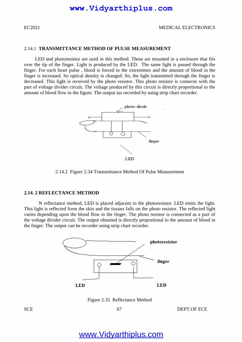
EC2021 MEDICAL ELECTRONICS
SCE 67 DEPT.OF ECE
2.14.1 TRANSMITTANCE METHOD OF PULSE MEASUREMENT
LED and photoresistor are used in this method. These are mounted in a enclosure that fitsover the tip of the finger. Light is produced by the LED. The same light is passed through thefinger. For each heart pulse , blood is forced to the extremities and the amount of blood in thefinger is increased. So optical density is changed. So, the light transmitted through the finger isdecreased. This light is received by the photo resistor. This photo resistor is connecte with thepart of voltage divider circuit. The voltage produced by this circuit is directly proportional to theamount of blood flow in the figure. The output ius recorded by using strip chart recorder.
2.14.2 Figuer 2.34 Transmittance Method Of Pulse Measurement
2.14. 2 REFLECTANCE METHOD
N reflectance method, LED is placed adjacent to the photoresistor. LED emits the light.This light is reflected form the skin and the tissues falls on the photo resistor. The reflected lightvaries depending upon the blood flow in the finger. The photo resistor is connected as a part ofthe voltage divider circuit. The output obtained is directly proportional to the amount of blood inthe finger. The output can be recorder using strip chart recorder.
Figure 2.35 Reflectance Method
www.Vidyarthiplus.com
www.Vidyarthiplus.com
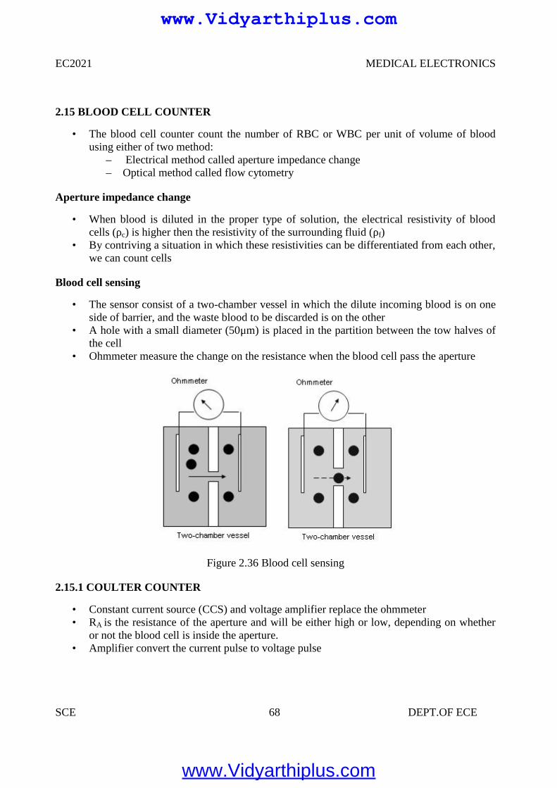
EC2021 MEDICAL ELECTRONICS
SCE 68 DEPT.OF ECE
2.15 BLOOD CELL COUNTER
• The blood cell counter count the number of RBC or WBC per unit of volume of bloodusing either of two method:
– Electrical method called aperture impedance change– Optical method called flow cytometry
Aperture impedance change
• When blood is diluted in the proper type of solution, the electrical resistivity of bloodcells (ρc) is higher then the resistivity of the surrounding fluid (ρf)
• By contriving a situation in which these resistivities can be differentiated from each other,we can count cells
Blood cell sensing
• The sensor consist of a two-chamber vessel in which the dilute incoming blood is on oneside of barrier, and the waste blood to be discarded is on the other
• A hole with a small diameter (50μm) is placed in the partition between the tow halves ofthe cell
• Ohmmeter measure the change on the resistance when the blood cell pass the aperture
Figure 2.36 Blood cell sensing
2.15.1 COULTER COUNTER
• Constant current source (CCS) and voltage amplifier replace the ohmmeter• RA is the resistance of the aperture and will be either high or low, depending on whether
or not the blood cell is inside the aperture.• Amplifier convert the current pulse to voltage pulse
www.Vidyarthiplus.com
www.Vidyarthiplus.com
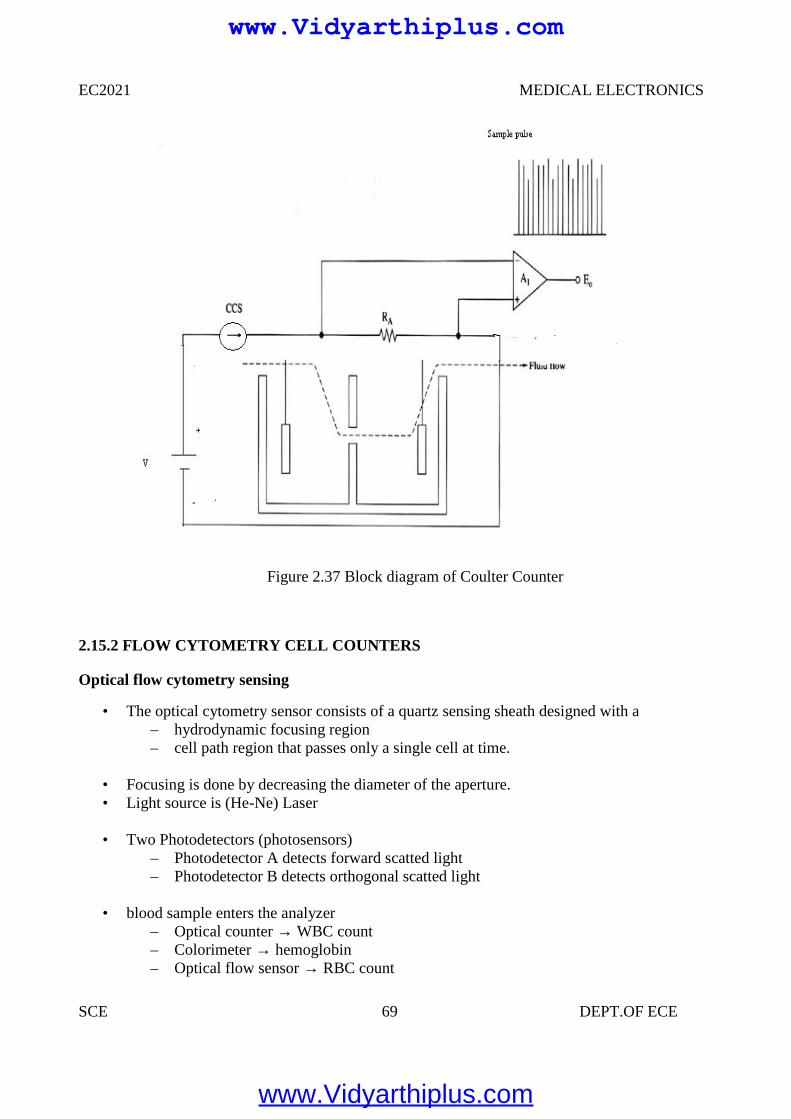
EC2021 MEDICAL ELECTRONICS
SCE 69 DEPT.OF ECE
Figure 2.37 Block diagram of Coulter Counter
2.15.2 FLOW CYTOMETRY CELL COUNTERS
Optical flow cytometry sensing
• The optical cytometry sensor consists of a quartz sensing sheath designed with a– hydrodynamic focusing region– cell path region that passes only a single cell at time.
• Focusing is done by decreasing the diameter of the aperture.• Light source is (He-Ne) Laser
• Two Photodetectors (photosensors)– Photodetector A detects forward scatted light– Photodetector B detects orthogonal scatted light
• blood sample enters the analyzer– Optical counter → WBC count– Colorimeter → hemoglobin– Optical flow sensor → RBC count
www.Vidyarthiplus.com
www.Vidyarthiplus.com
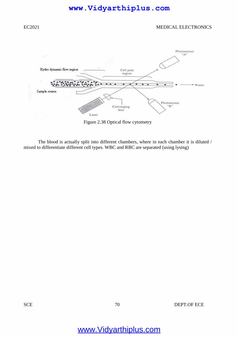
EC2021 MEDICAL ELECTRONICS
SCE 70 DEPT.OF ECE
Figure 2.38 Optical flow cytometry
The blood is actually split into different chambers, where in each chamber it is diluted /mixed to differentiate different cell types. WBC and RBC are separated (using lysing)
www.Vidyarthiplus.com
www.Vidyarthiplus.com
EC2021 MEDICAL ELECTRONICS
SCE 71 DEPT.OF ECE
UNIT III
ASSIST DEVICES AND BIO-TELEMETRY
3.1 CARDIAC PACEMAKERS
Definition:
A device capable of generating artificial pacing impulses and delivering them toheart is known as pacemaker system or pacemaker.
It consists of a pulse generator and electrodes. Sino Atrial node is responsible forthe starting of heart beat, hence it is called as Natural Pacemaker.
Types of pacemakers:
Internal pacemaker External pacemaker
3.1.1 INTERNAL PACEMAKER
It is placed inside the body. It may be permanently implanted on the patientswhose SA nodes are failed to function or those who suffered from permanent heart block. Internal pacemaker systems are implanted with the pulse generator placed in asurgically developed pocket below the right or left clavicle, in left sub costal region. In case of women it is placed beneath the left or right major pectoral’s muscle. Internal leads are connected to the electrodes that directly contact the surface ofthe myocardium. The exact location of the pulse generator used in the internal pacemaker systemdepends on the following factors.
Type and nature of the electrode used. Nature of the cardiac problems. Mode of operation of the pacemaker system.
There is no external connection for applying power. So the pulse generator shouldbe completely self contained with a battery, which is capable of operatingcontinuously for a specified period.
3.1.2 EXTERNAL PACEMAKER
It consists of an externally placed pulse generator circuit connected to theelectrodes placed on the myocardium. Temporary heart irregularities or disorders. Treating the patient from arrhythmias. Treatment of coronary patient and during the cardiac surgery.
www.Vidyarthiplus.com
www.Vidyarthiplus.com
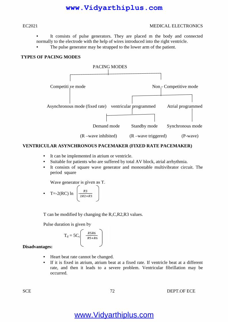
EC2021 MEDICAL ELECTRONICS
SCE 72 DEPT.OF ECE
It consists of pulse generators. They are placed m the body and connectednormally to the electrode with the help of wires introduced into the right ventricle. The pulse generator may be strapped to the lower arm of the patient.
TYPES OF PACING MODES
PACING MODES
Competiti ve mode Non - Competitive mode
Asynchronous mode (fixed rate) ventricular programmed Atrial programmed
Demand mode Standby mode Synchronous mode
(R –wave inhibited) (R –wave triggered) (P-wave)
VENTRICULAR ASYNCHRONOUS PACEMAKER (FIXED RATE PACEMAKER)
It can be implemented in atrium or ventricle. Suitable for patients who are suffered by total AV block, atrial arrhythmia. It consists of square wave generator and monostable multivibrator circuit. The
period square
Wave generator is given as T.
T=-2(RC) ln
T can be modified by changing the R,C,R2,R3 values.
Pulse duration is given by
Td = 5Cc
Disadvantages:
Heart beat rate cannot be changed. If it is fixed in atrium, atrium beat at a fixed rate. If ventricle beat at a different
rate, and then it leads to a severe problem. Ventricular fibrillation may beoccurred.
www.Vidyarthiplus.com
www.Vidyarthiplus.com
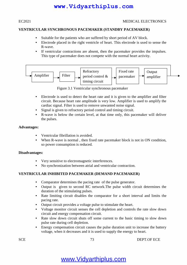
EC2021 MEDICAL ELECTRONICS
SCE 73 DEPT.OF ECE
VENTRICULAR SYNCHRONOUS PACEMAKER (STANDBY PACEMAKER)
Suitable for the patients who are suffered by short period of AV block. Electrode placed in the right ventricle of heart. This electrode is used to sense the
R-wave. If ventricular contractions are absent, then the pacemaker provides the impulses.
This type of pacemaker does not compete with the normal heart activity.
Figure 3.1 Ventricular synchronous pacemaker
Electrode is used to detect the heart rate and it is given to the amplifier and filtercircuit. Because heart rate amplitude is very low. Amplifier is used to amplify thecardiac signal. Filter is used to remove unwanted noise signal.
Signal is given to refractory period control and timing circuit. R-wave is below the certain level, at that time only, this pacemaker will deliver
the pulses.
Advantages:
Ventricular fibrillation is avoided. When R-wave is normal , then fixed rate pacemaker block is not in ON condition,
so power consumption is reduced.
Disadvantages:
Very sensitive to electromagnetic interferences. No synchronization between atrial and ventricular contraction.
VENTRICULAR INHIBITED PACEMAKER (DEMAND PACEMAKER)
Comparator determines the pacing rate of the pulse generator. Output is given to second RC network.The pulse width circuit determines the
duration of the stimulating pulses. Rate limiting circuit disables the comparator for a short interval and limits the
pacing rate. Output circuit provides a voltage pulse to stimulate the heart. Voltage monitor circuit senses the cell depletion and controls the rate slow down
circuit and energy compensation circuit. Rate slow down circuit shuts off some current to the basic timing to slow down
pulse rate during cell depletion. Energy compensation circuit causes the pulse duration unit to increase the battery
voltage, when it decreases and it is used to supply the energy to heart.
AmplifierOutputamplifierFilter
Refractoryperiod control &timing circuit
Fixed ratepacemaker
www.Vidyarthiplus.com
www.Vidyarthiplus.com
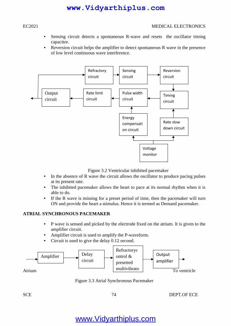
EC2021 MEDICAL ELECTRONICS
SCE 74 DEPT.OF ECE
Sensing circuit detects a spontaneous R-wave and resets the oscillator timingcapacitor.
Reversion circuit helps the amplifier to detect spontaneous R wave in the presenceof low level continuous wave interference.
Figure 3.2 Ventricular inhibited pacemaker In the absence of R wave the circuit allows the oscillator to produce pacing pulses
at its present rate. The inhibited pacemaker allows the heart to pace at its normal rhythm when it is
able to do. If the R wave is missing for a preset period of time, then the pacemaker will turn
ON and provide the heart a stimulus. Hence it is termed as Demand pacemaker.
ATRIAL SYNCHRONOUS PACEMAKER
P wave is sensed and picked by the electrode fixed on the atrium. It is given to theamplifier circuit.
Amplifier circuit is used to amplify the P-waveform. Circuit is used to give the delay 0.12 second.
Atrium To ventricle
Figure 3.3 Atrial Synchronous Pacemaker
Voltagemonitor
Outputcircuit
Rate limitcircuit
Refractorycircuit
Energycompensation circuit
Pulse widthcircuit
Sensingcircuit
Rate slowdown circuit
Timingcircuit
Reversioncircuit
Amplifier Delaycircuit
Refractorycontrol &presettedmultivibrator
Outputamplifier
www.Vidyarthiplus.com
www.Vidyarthiplus.com
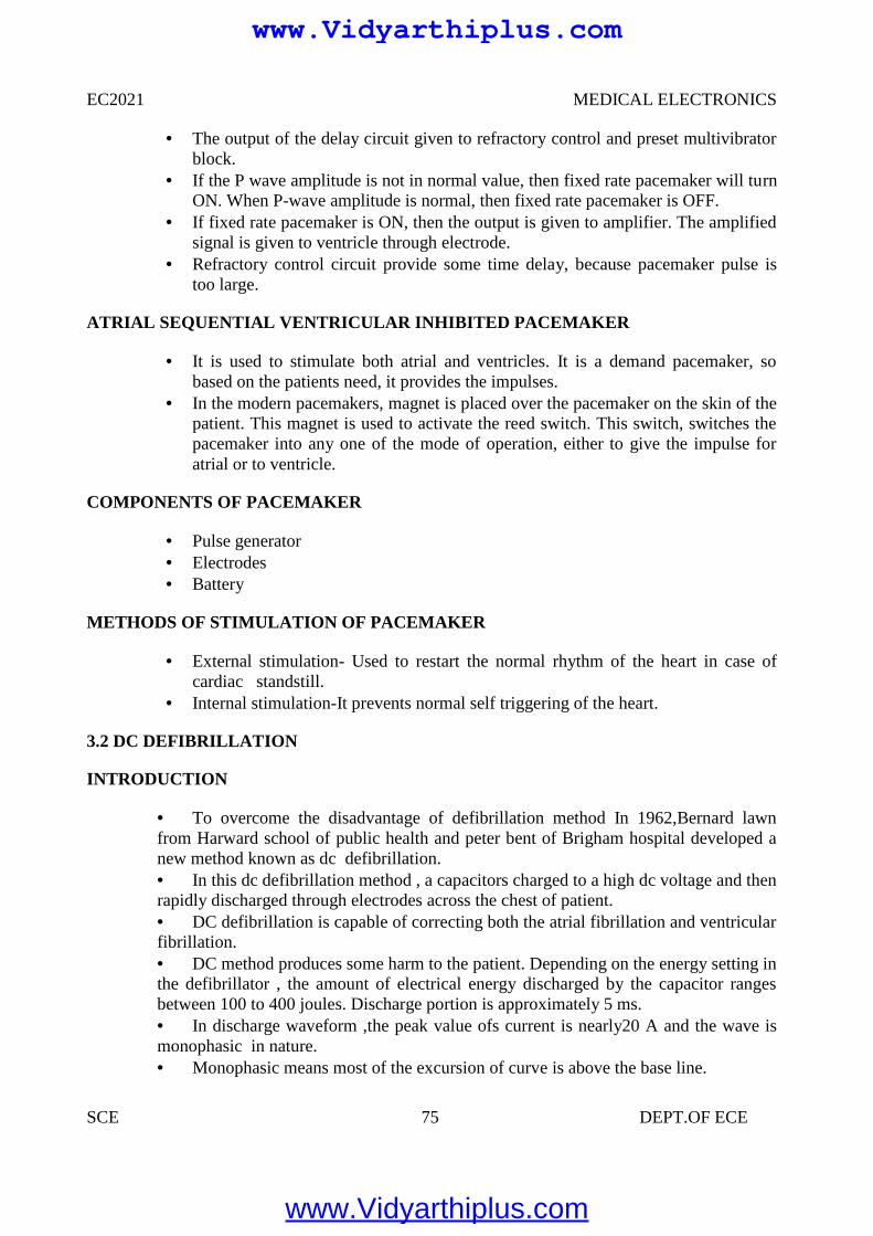
EC2021 MEDICAL ELECTRONICS
SCE 75 DEPT.OF ECE
The output of the delay circuit given to refractory control and preset multivibratorblock.
If the P wave amplitude is not in normal value, then fixed rate pacemaker will turnON. When P-wave amplitude is normal, then fixed rate pacemaker is OFF.
If fixed rate pacemaker is ON, then the output is given to amplifier. The amplifiedsignal is given to ventricle through electrode.
Refractory control circuit provide some time delay, because pacemaker pulse istoo large.
ATRIAL SEQUENTIAL VENTRICULAR INHIBITED PACEMAKER
It is used to stimulate both atrial and ventricles. It is a demand pacemaker, sobased on the patients need, it provides the impulses.
In the modern pacemakers, magnet is placed over the pacemaker on the skin of thepatient. This magnet is used to activate the reed switch. This switch, switches thepacemaker into any one of the mode of operation, either to give the impulse foratrial or to ventricle.
COMPONENTS OF PACEMAKER
Pulse generator Electrodes Battery
METHODS OF STIMULATION OF PACEMAKER
External stimulation- Used to restart the normal rhythm of the heart in case ofcardiac standstill.
Internal stimulation-It prevents normal self triggering of the heart.
3.2 DC DEFIBRILLATION
INTRODUCTION
To overcome the disadvantage of defibrillation method In 1962,Bernard lawnfrom Harward school of public health and peter bent of Brigham hospital developed anew method known as dc defibrillation. In this dc defibrillation method , a capacitors charged to a high dc voltage and thenrapidly discharged through electrodes across the chest of patient. DC defibrillation is capable of correcting both the atrial fibrillation and ventricularfibrillation. DC method produces some harm to the patient. Depending on the energy setting inthe defibrillator , the amount of electrical energy discharged by the capacitor rangesbetween 100 to 400 joules. Discharge portion is approximately 5 ms. In discharge waveform ,the peak value ofs current is nearly20 A and the wave ismonophasic in nature. Monophasic means most of the excursion of curve is above the base line.
www.Vidyarthiplus.com
www.Vidyarthiplus.com
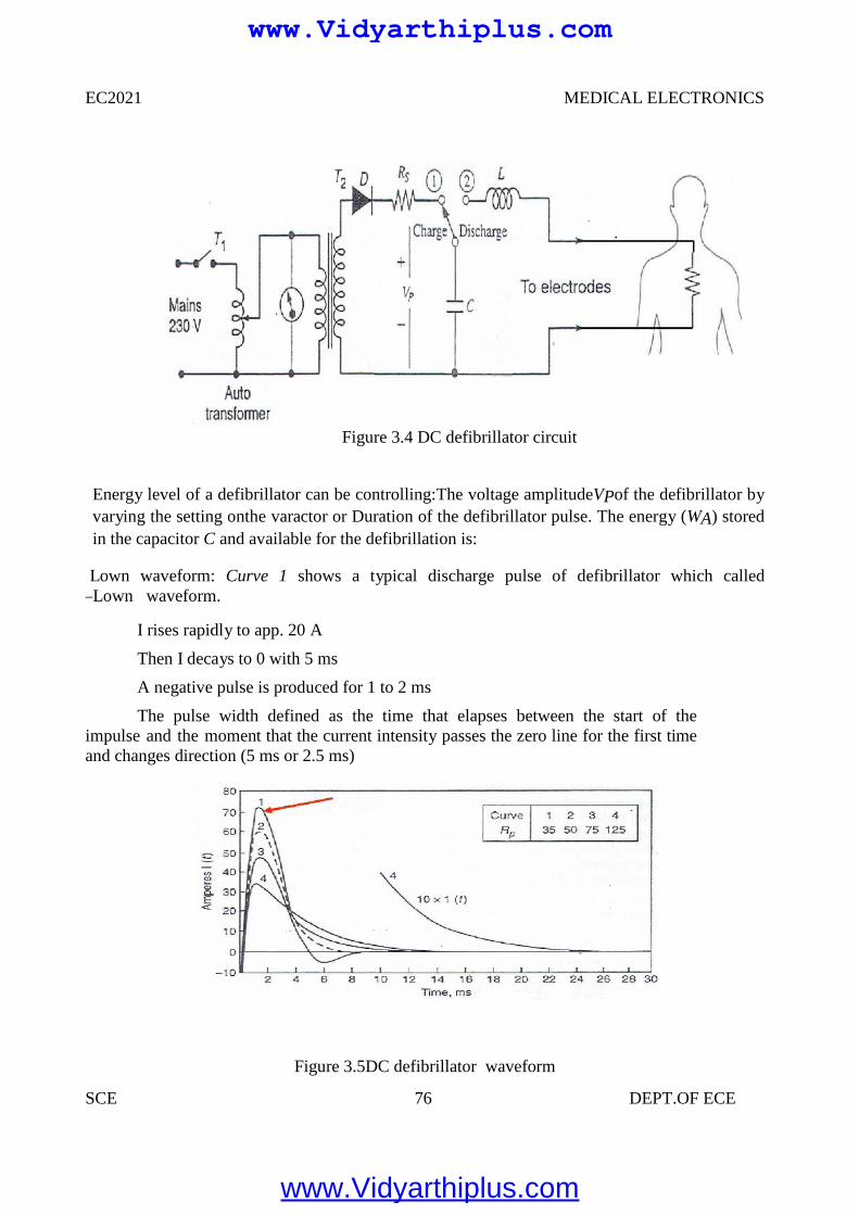
EC2021 MEDICAL ELECTRONICS
SCE 76 DEPT.OF ECE
Figure 3.4 DC defibrillator circuit
Energy level of a defibrillator can be controlling:The voltage amplitudeVPof the defibrillator byvarying the setting onthe varactor or Duration of the defibrillator pulse. The energy (WA) storedin the capacitor C and available for the defibrillation is:
Lown waveform: Curve 1 shows a typical discharge pulse of defibrillator which called―Lown waveform.
I rises rapidly to app. 20 A
Then I decays to 0 with 5 ms
A negative pulse is produced for 1 to 2 ms
The pulse width defined as the time that elapses between the start of theimpulse and the moment that the current intensity passes the zero line for the first timeand changes direction (5 ms or 2.5 ms)
Figure 3.5DC defibrillator waveform
www.Vidyarthiplus.com
www.Vidyarthiplus.com
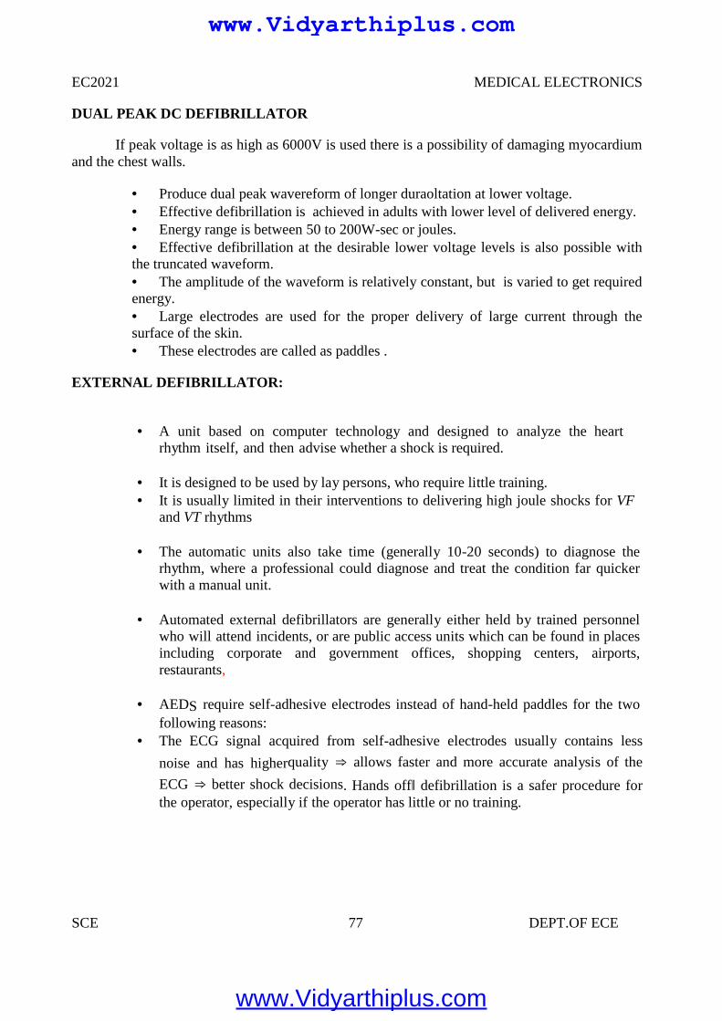
EC2021 MEDICAL ELECTRONICS
SCE 77 DEPT.OF ECE
DUAL PEAK DC DEFIBRILLATOR
If peak voltage is as high as 6000V is used there is a possibility of damaging myocardiumand the chest walls.
Produce dual peak wavereform of longer duraoltation at lower voltage. Effective defibrillation is achieved in adults with lower level of delivered energy. Energy range is between 50 to 200W-sec or joules. Effective defibrillation at the desirable lower voltage levels is also possible withthe truncated waveform. The amplitude of the waveform is relatively constant, but is varied to get requiredenergy. Large electrodes are used for the proper delivery of large current through thesurface of the skin. These electrodes are called as paddles .
EXTERNAL DEFIBRILLATOR:
A unit based on computer technology and designed to analyze the heartrhythm itself, and then advise whether a shock is required.
It is designed to be used by lay persons, who require little training. It is usually limited in their interventions to delivering high joule shocks for VF
and VT rhythms
The automatic units also take time (generally 10-20 seconds) to diagnose therhythm, where a professional could diagnose and treat the condition far quickerwith a manual unit.
Automated external defibrillators are generally either held by trained personnelwho will attend incidents, or are public access units which can be found in placesincluding corporate and government offices, shopping centers, airports,restaurants,
AEDS require self-adhesive electrodes instead of hand-held paddles for the twofollowing reasons:
The ECG signal acquired from self-adhesive electrodes usually contains less
noise and has higherquality ⇒ allows faster and more accurate analysis of the
ECG ⇒ better shock decisions. Hands off‖ defibrillation is a safer procedure forthe operator, especially if the operator has little or no training.
www.Vidyarthiplus.com
www.Vidyarthiplus.com
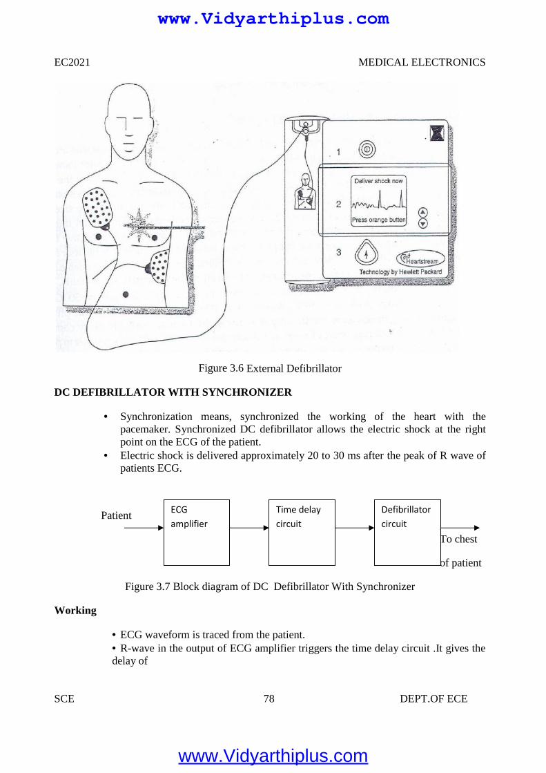
EC2021 MEDICAL ELECTRONICS
SCE 78 DEPT.OF ECE
Figure 3.6 External Defibrillator
DC DEFIBRILLATOR WITH SYNCHRONIZER
Synchronization means, synchronized the working of the heart with thepacemaker. Synchronized DC defibrillator allows the electric shock at the rightpoint on the ECG of the patient.
Electric shock is delivered approximately 20 to 30 ms after the peak of R wave ofpatients ECG.
Patient
To chest
of patient
Figure 3.7 Block diagram of DC Defibrillator With Synchronizer
Working
ECG waveform is traced from the patient. R-wave in the output of ECG amplifier triggers the time delay circuit .It gives thedelay of
ECGamplifier
Time delaycircuit
Defibrillatorcircuit
www.Vidyarthiplus.com
www.Vidyarthiplus.com
EC2021 MEDICAL ELECTRONICS
SCE 79 DEPT.OF ECE
30 ms approximately. After that, defibrillator circuit is switched ON. So that, thecapacitor discharges the electric shock to the patient’s heart. The moment at which electric shock occurs is noted by producing the markerpulse on monitoring display. This type of circuit is preferred in cardiac emergencies The sudden cardiac arrest can be treated using a defibrillator and 80 percent of thepatients will be cured from the cardiac arrest if the is given within one minute of theattack.
Electrodes used for defibrillation
These paddles have metal disks of 8 to 10 cm in diameter for external use. For internal use smaller paddles are used on infants and children. For external use, pair of electrodes are firmly pressed against the patients chest.
Need of Insulation Handle
To prevent the person applying the electrodes from accidential electric shockspecially insulated handles are provided in the paddles.
When paddles are properly positioned , this prevents the patient from receiving ashock.
In earlier equipment a foot switch is used instead of thumb switch.
Need of Thumb Switch
There is a possibility of someone accidentally stepping on the foot switch in theexcitement of an emergency before the paddles are placed. So thumb switches aremostly preferred.
Charging of Defibrillators
In some defibrillators charging is done by means of a charge switch located in thefront panel of the unit.
The charge switch is located in the handle of one of its paddles. In few defibrillators the charging process begins automatically after discharge.
Types of Electrodes
Two electrodes are Anterior-anterior Anterior-posterior
Anterior-anterior paddles are applied to the chest. Anterior-posterior paddles areapplied to both the patients chest wall and back so that energy is delivered throughthe heart.
Specially designed pediatric paddles are available with diameter ranging from 2 to6 cm.
Internal paddles can be either gas-sterilized or autoclaved.
www.Vidyarthiplus.com
www.Vidyarthiplus.com
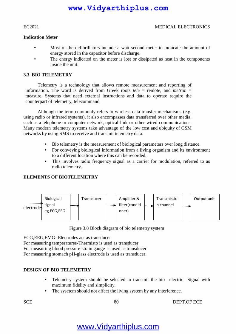
EC2021 MEDICAL ELECTRONICS
SCE 80 DEPT.OF ECE
Indication Meter
Most of the defibrillators include a watt second meter to inducate the amount ofenergy stored in the capacitor before discharge.
The energy indicated on the meter is lost or dissipated as heat in the componentsinside the unit.
3.3 BIO TELEMETRY
Telemetry is a technology that allows remote measurement and reporting ofinformation. The word is derived from Greek roots tele = remote, and metron =measure. Systems that need external instructions and data to operate require thecounterpart of telemetry, telecommand.
Although the term commonly refers to wireless data transfer mechanisms (e.g.using radio or infrared systems), it also encompasses data transferred over other media,such as a telephone or computer network, optical link or other wired communications.Many modern telemetry systems take advantage of the low cost and ubiquity of GSMnetworks by using SMS to receive and transmit telemetry data.
Bio telemetry is the measurement of biological parameters over long distance. For conveying biological information from a living organism and its environment
to a different location where this can be recorded. This involves radio frequency signal as a carrier for modulation, referred to as
radio telemetry.
ELEMENTS OF BIOTELEMETRY
electrodes
Figure 3.8 Block diagram of bio telemetry system
ECG,EEG,EMG- Electrodes act as transducerFor measuring temperatures-Thermisto is used as transducerFor measuring blood pressure-strain gauge is used as transducerFor measuring stomach pH-glass electrode is used as transducer.
DESIGN OF BIO TELEMETRY
Telemetry system should be selected to transmit the bio –electric Signal withmaximum fidelity and simplicity.
The sysetem should not affect the living system by any interference.
Biologicalsignaleg.ECG,EEG
Transducer Amplifier &filter(conditioner)
Transmission channel
Output unit
www.Vidyarthiplus.com
www.Vidyarthiplus.com
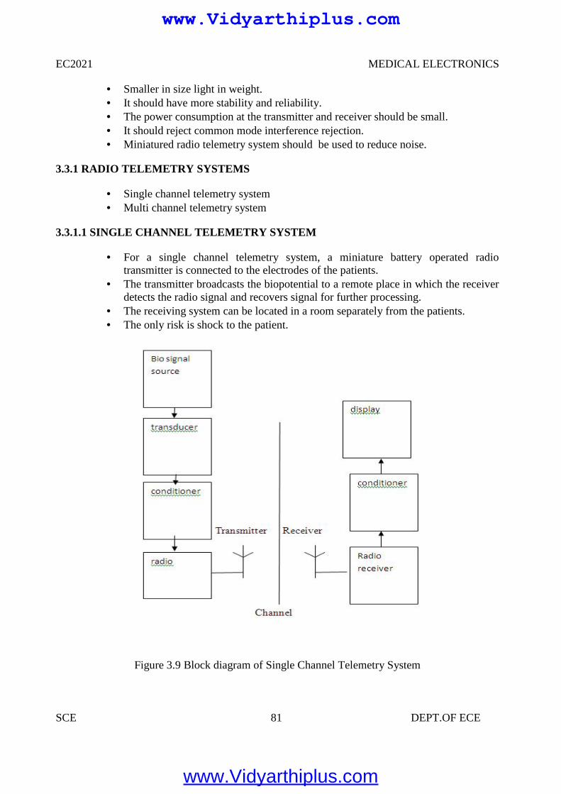
EC2021 MEDICAL ELECTRONICS
SCE 81 DEPT.OF ECE
Smaller in size light in weight. It should have more stability and reliability. The power consumption at the transmitter and receiver should be small. It should reject common mode interference rejection. Miniatured radio telemetry system should be used to reduce noise.
3.3.1 RADIO TELEMETRY SYSTEMS
Single channel telemetry system Multi channel telemetry system
3.3.1.1 SINGLE CHANNEL TELEMETRY SYSTEM
For a single channel telemetry system, a miniature battery operated radiotransmitter is connected to the electrodes of the patients.
The transmitter broadcasts the biopotential to a remote place in which the receiverdetects the radio signal and recovers signal for further processing.
The receiving system can be located in a room separately from the patients. The only risk is shock to the patient.
Figure 3.9 Block diagram of Single Channel Telemetry System
www.Vidyarthiplus.com
www.Vidyarthiplus.com
EC2021 MEDICAL ELECTRONICS
SCE 82 DEPT.OF ECE
Biosignal from the patient is converted into electrical signals by the transducer. They are amplified and filtered at the conditioner. Further they are frequency
modulated or pulse modulated.Frequency modulation provides the high noiseinterference rejection and high stability.
The biosignals are amplified to radio frequency range of few hundred KHz toabout 300 KHz and then they are transmitted by transmitter antenna.s
At radio receiver the corresponding frequency are received and then they aredemodulated, amplified and displayed.
Transmission of bioelectric variables:
Active measurements Passive measurements
Tunnel diode FM transmitter The tunnel diodes exhibit a specific characteristics known as negative resistance.
They have extremely low values of inductance an capacitance. It is used for the transmission of EMG,ECG, respiration rates. Tunnel diodes are used as active devices and this circuit has higher fidelity and
sensitivity. Total weight is 1.44 gm with battery and the size is small. Varactor diode is basically a reverse biased PN junction which utilizes the
inherent capacitance of depletion layer. Varactor diodes are voltage capacitors used for frequency modulation. The signal is transmitted through the inductor L of the tank circuit of RF
oscillator.
Advantages:
All the signal can be transmitted by using the circuit. No shielded room is needed. Interference is much reduced.
Radio telemetry with sub carrier sytem:
Transmitter side:
When the position of transmitter to the body or other conduction object change, the carrierfrequency and amplitude will change due to the loading change of the carrier frequencyresonant circuit.
If the signal has a frequency different from the loading effect ,they can be separated byfilters. .Otherwise the real signal will be distorted by loading effect.
To avoid this loading effect the sub carrier system is needed. The signal is modulated ona sub carrier to convert the signal frequency to the neighbourhood of the sub carrierfrequency.
Then the RF carrier is modulated by this sub carrier carrying the signal. The 20 KHz sub carrier signal is given to amplitude modulator. The signals are amplified and forwarded to the transmitter.
www.Vidyarthiplus.com
www.Vidyarthiplus.com
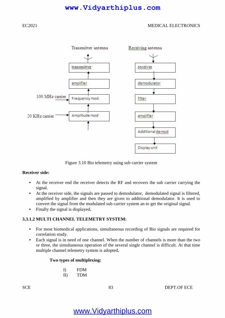
EC2021 MEDICAL ELECTRONICS
SCE 83 DEPT.OF ECE
Figure 3.10 Bio telemetry using sub carrier system
Receiver side:
At the receiver end the receiver detects the RF and recovers the sub carrier carrying thesignal.
At the receiver side, the signals are passed to demodulator, demodulated signal is filtered,amplified by amplifier and then they are given to additional demodulator. It is used toconvert the signal from the modulated sub carrier system an to get the original signal.
Finally the signal is displayed.
3.3.1.2 MULTI CHANNEL TELEMETRY SYSTEM:
For most biomedical applications, simultaneous recording of Bio signals are required forcorrelation study.
Each signal is in need of one channel. When the number of channels is more than the twoor three, the simultaneous operation of the several single channel is difficult. At that timemultiple channel telemetry system is adopted.
Two types of multiplexing:
I) FDMII) TDM
www.Vidyarthiplus.com
www.Vidyarthiplus.com
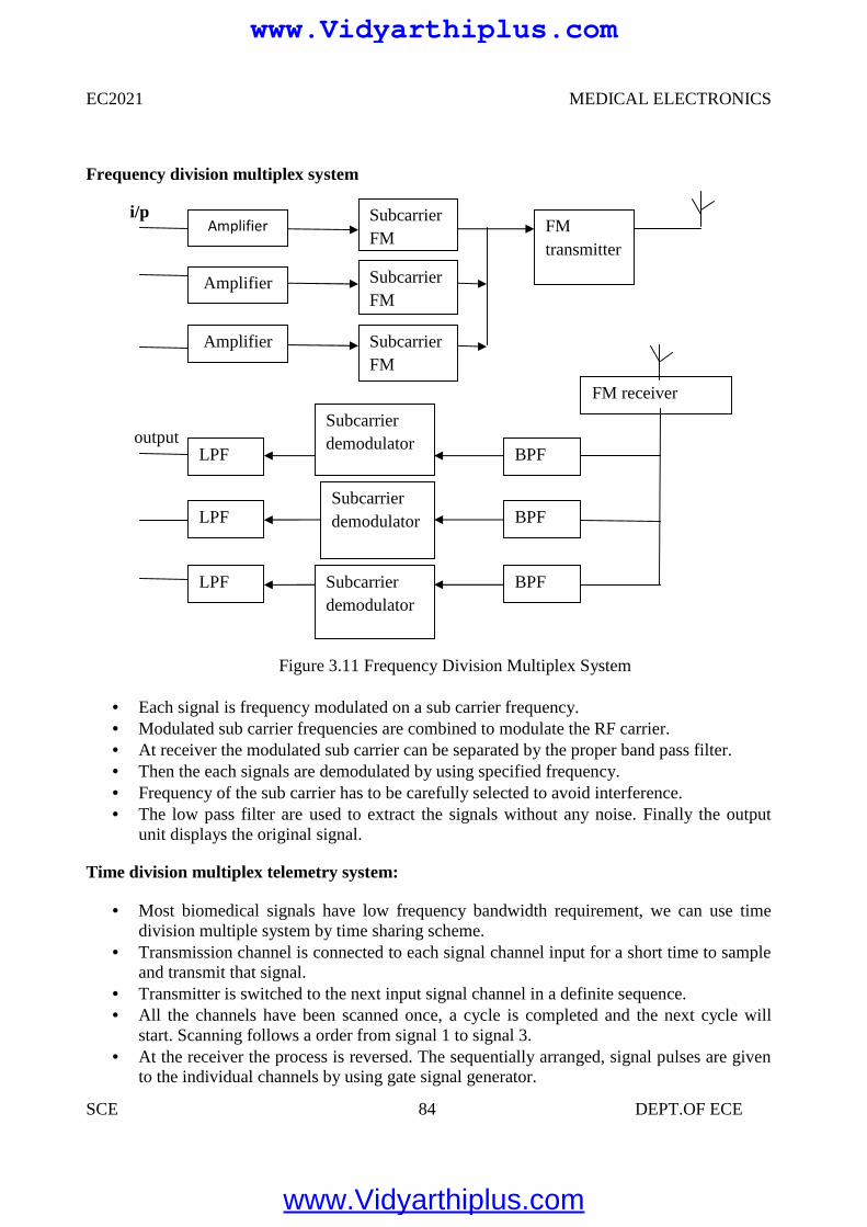
EC2021 MEDICAL ELECTRONICS
SCE 84 DEPT.OF ECE
Frequency division multiplex system
i/p
output
Figure 3.11 Frequency Division Multiplex System
Each signal is frequency modulated on a sub carrier frequency. Modulated sub carrier frequencies are combined to modulate the RF carrier. At receiver the modulated sub carrier can be separated by the proper band pass filter. Then the each signals are demodulated by using specified frequency. Frequency of the sub carrier has to be carefully selected to avoid interference. The low pass filter are used to extract the signals without any noise. Finally the output
unit displays the original signal.
Time division multiplex telemetry system:
Most biomedical signals have low frequency bandwidth requirement, we can use timedivision multiple system by time sharing scheme.
Transmission channel is connected to each signal channel input for a short time to sampleand transmit that signal.
Transmitter is switched to the next input signal channel in a definite sequence. All the channels have been scanned once, a cycle is completed and the next cycle will
start. Scanning follows a order from signal 1 to signal 3. At the receiver the process is reversed. The sequentially arranged, signal pulses are given
to the individual channels by using gate signal generator.
Amplifier
Amplifier
Amplifier
SubcarrierFM
SubcarrierFM
SubcarrierFM
FMtransmitter
Subcarrierdemodulator
Subcarrierdemodulator
Subcarrierdemodulator
BPF
BPF
BPF
LPF
LPF
LPF
FM receiverdemod
www.Vidyarthiplus.com
www.Vidyarthiplus.com
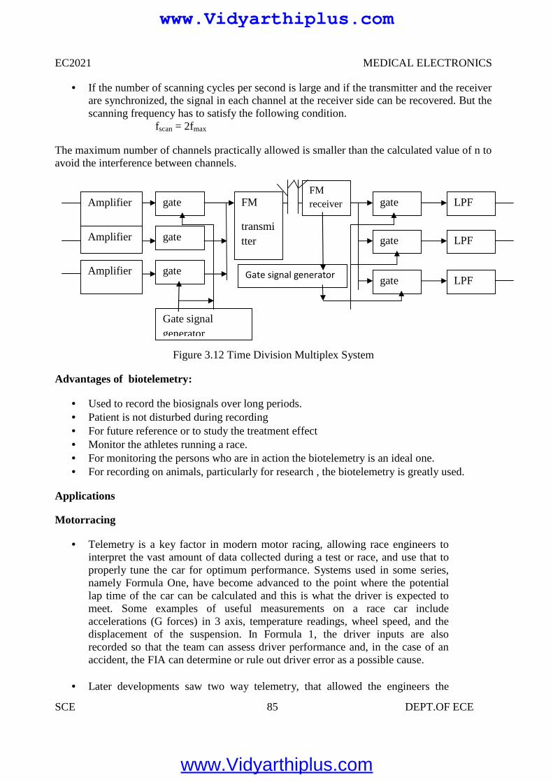
EC2021 MEDICAL ELECTRONICS
SCE 85 DEPT.OF ECE
If the number of scanning cycles per second is large and if the transmitter and the receiverare synchronized, the signal in each channel at the receiver side can be recovered. But thescanning frequency has to satisfy the following condition.
fscan = 2fmax
The maximum number of channels practically allowed is smaller than the calculated value of n toavoid the interference between channels.
Figure 3.12 Time Division Multiplex System
Advantages of biotelemetry:
Used to record the biosignals over long periods. Patient is not disturbed during recording For future reference or to study the treatment effect Monitor the athletes running a race. For monitoring the persons who are in action the biotelemetry is an ideal one. For recording on animals, particularly for research , the biotelemetry is greatly used.
Applications
Motorracing
Telemetry is a key factor in modern motor racing, allowing race engineers tointerpret the vast amount of data collected during a test or race, and use that toproperly tune the car for optimum performance. Systems used in some series,namely Formula One, have become advanced to the point where the potentiallap time of the car can be calculated and this is what the driver is expected tomeet. Some examples of useful measurements on a race car includeaccelerations (G forces) in 3 axis, temperature readings, wheel speed, and thedisplacement of the suspension. In Formula 1, the driver inputs are alsorecorded so that the team can assess driver performance and, in the case of anaccident, the FIA can determine or rule out driver error as a possible cause.
Later developments saw two way telemetry, that allowed the engineers the
Amplifier
Amplifier
Amplifier
gate
gate
gate
FM
transmitter
FMreceiver
Gate signal generator
gate
gate
gate
LPF
LPF
LPF
Gate signalgenerator
www.Vidyarthiplus.com
www.Vidyarthiplus.com
EC2021 MEDICAL ELECTRONICS
SCE 86 DEPT.OF ECE
ability to update calibrations on the car in real time, possibly while it is out onthe track. In Formula 1, two-way telemetry surfaced in the early nineties fromTAG electronics, and consisted of a message display on the dashboard whichthe team could update. Its development continued until May 2001, at whichpoint it was first allowed on the cars. By
2002 the teams were able to change engine mapping and deactivate particularengine sensors from the pits while the car was on track. For the 2003 season,the FIA banned two-way telemetry from Formula 1, however thetechnology still exists and could eventually find its way into other forms ofracing or road cars.
In addition to that telemetry has also been applied to the use of Yacht racing.The technology was applied to the Oracle's USA-76.
Agriculture
Most activities related to healthy crops and good yields depend on timelyavailability of weather and soil data. Therefore, wireless weather stations play amajor role in disease prevention and precision irrigation. These stationstransmit major parameters needed for good decisions to a base station: airtemperature and relative humidity, precipitation and leaf wetness (for diseaseprediction models), solar radiation and wind speed (to calculateevapotranspiration), water deficit stress (WDS) leaf sensors and soil moisture,crucial to understand the progress of water into soil and roots for irrigationdecisions.
Because local micro-climates can vary significantly, such data needs to comefrom right within the crop. Monitoring stations usually transmit data back byterrestrial radio though occasionally satellite systems are used. Solar power isoften employed to make the station independent from local infrastructure.
Water Management
Telemetry has become indispensable for water management applications,including water quality and stream gauging functions. Major applicationsinclude AMR (automatic meter reading), groundwater monitoring, leakdetection in distribution pipelines and equipment surveillance. Having dataavailable in almost real time allows quick reactions to occurrences in the field.
Defense, space and resource exploration systems
Telemetry is an enabling technology for large complex systems such asmissiles, RPVs, spacecraft, oil rigs and chemical plants because it allowsautomatic monitoring, alerting, and record-keeping necessary for safe,efficient operations. Space agencies asNASA, ESA, and otheragencies use telemetry/telecommand systems to collect data from operatingspacecraft and satellites.
Telemetry is vital in the development phase of missiles, satellites and aircraft
www.Vidyarthiplus.com
www.Vidyarthiplus.com
EC2021 MEDICAL ELECTRONICS
SCE 87 DEPT.OF ECE
because the system might be destroyed after/during the test. Engineers needcritical system parameters to analyze (and improve) the performance of thesystem. Without telemetry, these data would often be unavailable
Rocketry
In rocketry, telemetry equipment forms an integral part of the rocket rangeassets used to monitor the progress of a rocket launch. Some special problemsare the extreme environment (temperature, accelerations, vibrations...), theenergy supply, the precise alignment of the antenna and (at long distances, e.g.in spaceflight) the signal travel time.
Flight Test
Flight test programs typically telemeter data collected from on-board flight test
instrumentation over a PCM/RF link.[4] This data is analyzed in real-time forsafety reasons and to provide feedback to the test pilot. Particular challengesfor telemetering this data includes fading, multipath propagation and theDoppler effect. The bandwidth of the telemetry link is often insufficient totransfer all the data acquired and therefore only a limited set is sent to theground for real-time processing while an on-board recorder ensures the fulldataset is available for post flight analysis.
Enemy Intelligence
Telemetry was a vital source of intelligence for the US and UK when Sovietmissiles were tested. For this purpose, the US operated a listening post in Iran.Eventually, the Russians discovered this kind of US intelligence gathering andencrypted their telemetry signals of missile tests. Telemetry was a vital sourcefor the Soviets who would operate listening ships in Cardigan Bay to eavesdropon the UK missile tests carried out there.
ENERGY MONITORING
In factories, buildings, and houses, energy consumption of systems such asHVAC are monitored at multiple locations, together with the relatedparameters (e.g. temperature) via wireless telemetry to one central location. Theinformation is collected and processed enabling intelligent decisions regardingthe most efficient use of energy to be implemented. Such systems also facilitatepredictive maintenance.
www.Vidyarthiplus.com
www.Vidyarthiplus.com
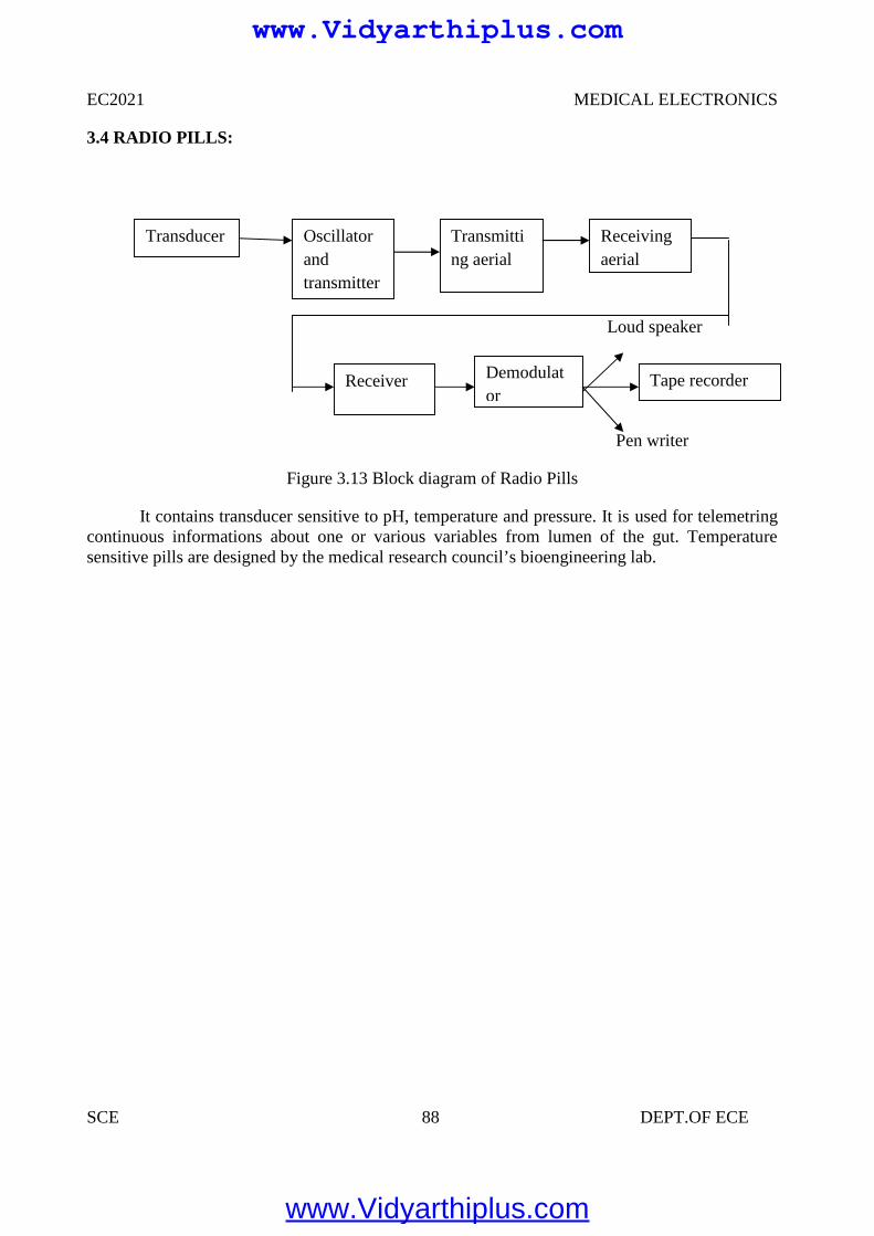
EC2021 MEDICAL ELECTRONICS
SCE 88 DEPT.OF ECE
3.4 RADIO PILLS:
Loud speaker
Pen writer
Figure 3.13 Block diagram of Radio Pills
It contains transducer sensitive to pH, temperature and pressure. It is used for telemetringcontinuous informations about one or various variables from lumen of the gut. Temperaturesensitive pills are designed by the medical research council’s bioengineering lab.
Transducer
Tape recorderReceiver Demodulator
Oscillatorandtransmitter
Transmitting aerial
Receivingaerial
www.Vidyarthiplus.com
www.Vidyarthiplus.com
EC2021 MEDICAL ELECTRONICS
SCE 89 DEPT.OF ECE
UNIT IV
RADIOLOGICAL EQUIPMENTS
4.1 IONISING RADIATION
In general, ionizing radiation is harmful and potentially lethal to living beings but canhave health benefits in radiation therapy for the treatment of cancer and thyrotoxicosis.
Most adverse health effects of radiation exposure may be grouped in two general categories:
Deterministic effects (harmful tissue reactions) due in large part to the killing/malfunction of cells following high doses; and
Stochastic effects, i.e., cancer and heritable effects involving either cancer development inexposed individuals owing to mutation of somatic cells or heritable disease in theiroffspring owing to mutation of reproductive (germ) cells.
Its most common impact is the stochastic induction of cancer with a latent period of yearsor decades after exposure. The mechanism by which this occurs is well understood, butquantitative models predicting the level of risk remain controversial. The most widely acceptedmodel posits that the incidence of cancers due to ionizing radiation increases linearly witheffective radiation dose at a rate of 5.5% per sievert. If this linear model is correct, then naturalbackground radiation is the most hazardous source of radiation to general public health, followedby medical imaging as a close second. Other stochastic effects of ionizing radiation areteratogenesis, cognitive decline, and heart disease.
High radiation dose gives rise to Deterministic effects which reliably occur above athreshold, and their severity increases with dose. Deterministic effects are not necessarily more orless serious than stochastic effects; either can ultimately lead to a temporary nuisance or afatality. Examples are: radiation burns, and/or rapid fatality through acute radiation syndrome,chronic radiation syndrome, and radiation-induced thyroiditis.
Beneficially, controlled doses are used for medical imaging and radiotherapy, and somescientists suspect that low doses may have a mild hormetic effect that can improve health, but theUS National Academy of Sciences Biological Effects of Ionizing Radiation Committee "hasconcluded that there is no compelling evidence to indicate a dose threshold below which the riskof tumor induction is zero
When alpha particle emitting isotopes are ingested, they are far more dangerous than theirhalf-life or decay rate would suggest. This is due to the high relative biological effectiveness ofalpha radiation to cause biological damage after alpha-emitting radioisotopes enter living cells.Ingested alpha emitter radioisotopes such as transuranics or actinides are an average of about 20times more dangerous, and in some experiments up to 1000 times more dangerous than anequivalent activity of beta emitting or gamma emitting radioisotopes.
www.Vidyarthiplus.com
www.Vidyarthiplus.com
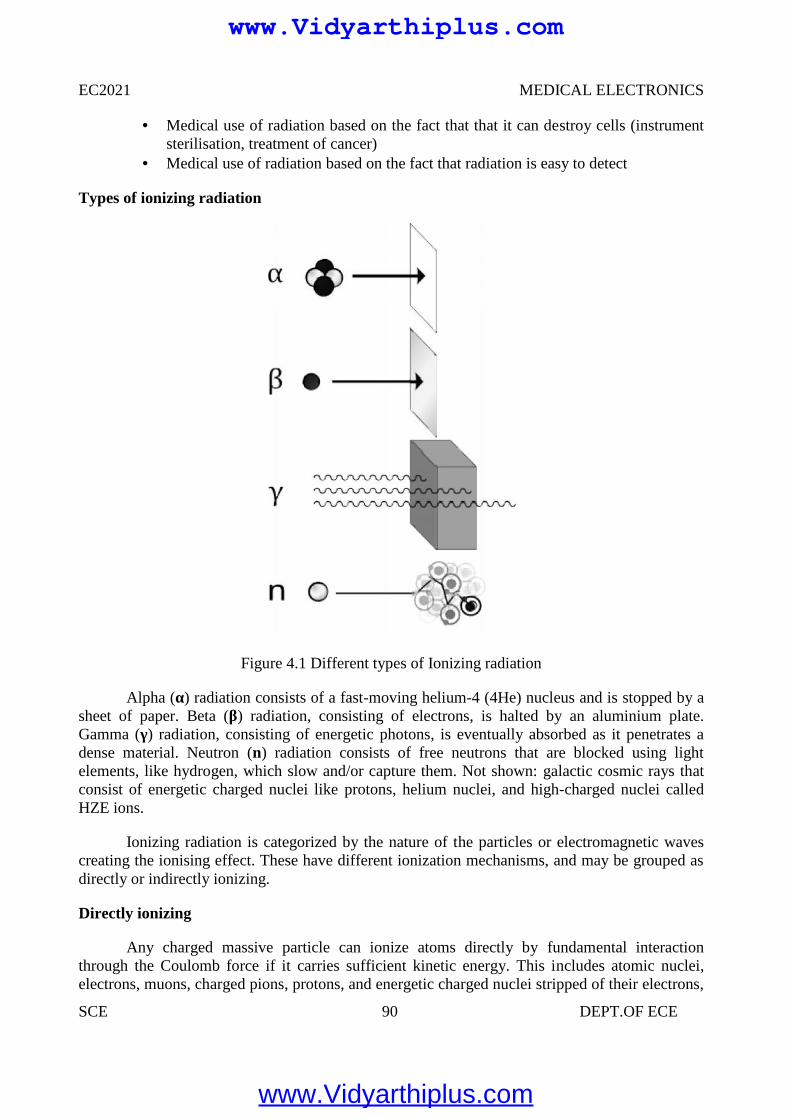
EC2021 MEDICAL ELECTRONICS
SCE 90 DEPT.OF ECE
Medical use of radiation based on the fact that that it can destroy cells (instrumentsterilisation, treatment of cancer)
Medical use of radiation based on the fact that radiation is easy to detect
Types of ionizing radiation
Figure 4.1 Different types of Ionizing radiation
Alpha (α) radiation consists of a fast-moving helium-4 (4He) nucleus and is stopped by asheet of paper. Beta (β) radiation, consisting of electrons, is halted by an aluminium plate.Gamma (γ) radiation, consisting of energetic photons, is eventually absorbed as it penetrates adense material. Neutron (n) radiation consists of free neutrons that are blocked using lightelements, like hydrogen, which slow and/or capture them. Not shown: galactic cosmic rays thatconsist of energetic charged nuclei like protons, helium nuclei, and high-charged nuclei calledHZE ions.
Ionizing radiation is categorized by the nature of the particles or electromagnetic wavescreating the ionising effect. These have different ionization mechanisms, and may be grouped asdirectly or indirectly ionizing.
Directly ionizing
Any charged massive particle can ionize atoms directly by fundamental interactionthrough the Coulomb force if it carries sufficient kinetic energy. This includes atomic nuclei,electrons, muons, charged pions, protons, and energetic charged nuclei stripped of their electrons,
www.Vidyarthiplus.com
www.Vidyarthiplus.com
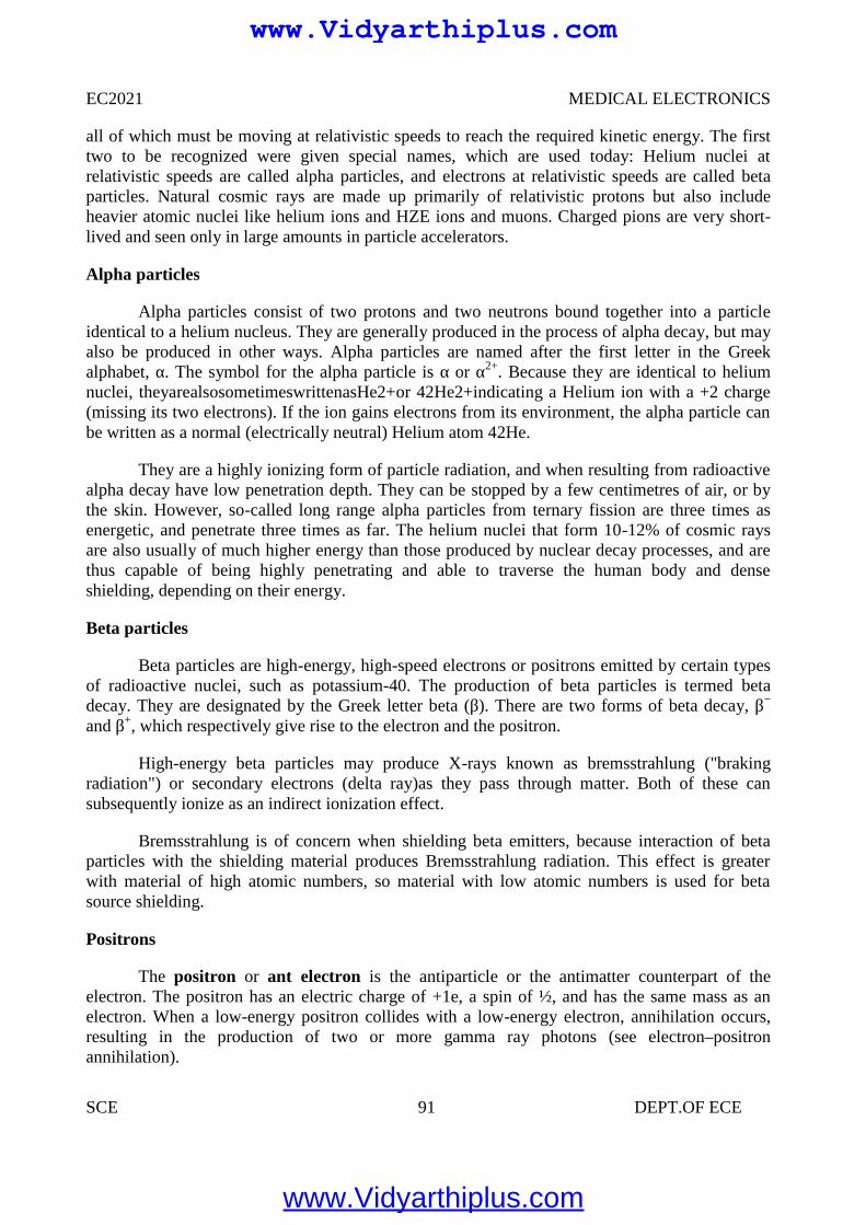
EC2021 MEDICAL ELECTRONICS
SCE 91 DEPT.OF ECE
all of which must be moving at relativistic speeds to reach the required kinetic energy. The firsttwo to be recognized were given special names, which are used today: Helium nuclei atrelativistic speeds are called alpha particles, and electrons at relativistic speeds are called betaparticles. Natural cosmic rays are made up primarily of relativistic protons but also includeheavier atomic nuclei like helium ions and HZE ions and muons. Charged pions are very short-lived and seen only in large amounts in particle accelerators.
Alpha particles
Alpha particles consist of two protons and two neutrons bound together into a particleidentical to a helium nucleus. They are generally produced in the process of alpha decay, but mayalso be produced in other ways. Alpha particles are named after the first letter in the Greekalphabet, α. The symbol for the alpha particle is α or α2+. Because they are identical to heliumnuclei, theyarealsosometimeswrittenasHe2+or 42He2+indicating a Helium ion with a +2 charge(missing its two electrons). If the ion gains electrons from its environment, the alpha particle canbe written as a normal (electrically neutral) Helium atom 42He.
They are a highly ionizing form of particle radiation, and when resulting from radioactivealpha decay have low penetration depth. They can be stopped by a few centimetres of air, or bythe skin. However, so-called long range alpha particles from ternary fission are three times asenergetic, and penetrate three times as far. The helium nuclei that form 10-12% of cosmic raysare also usually of much higher energy than those produced by nuclear decay processes, and arethus capable of being highly penetrating and able to traverse the human body and denseshielding, depending on their energy.
Beta particles
Beta particles are high-energy, high-speed electrons or positrons emitted by certain typesof radioactive nuclei, such as potassium-40. The production of beta particles is termed betadecay. They are designated by the Greek letter beta (β). There are two forms of beta decay, β−
and β+, which respectively give rise to the electron and the positron.
High-energy beta particles may produce X-rays known as bremsstrahlung ("brakingradiation") or secondary electrons (delta ray)as they pass through matter. Both of these cansubsequently ionize as an indirect ionization effect.
Bremsstrahlung is of concern when shielding beta emitters, because interaction of betaparticles with the shielding material produces Bremsstrahlung radiation. This effect is greaterwith material of high atomic numbers, so material with low atomic numbers is used for betasource shielding.
Positrons
The positron or ant electron is the antiparticle or the antimatter counterpart of theelectron. The positron has an electric charge of +1e, a spin of ½, and has the same mass as anelectron. When a low-energy positron collides with a low-energy electron, annihilation occurs,resulting in the production of two or more gamma ray photons (see electron–positronannihilation).
www.Vidyarthiplus.com
www.Vidyarthiplus.com
EC2021 MEDICAL ELECTRONICS
SCE 92 DEPT.OF ECE
Positrons may be generated by positron emission radioactive decay (through weak interactions),or by pair production from a sufficiently energetic photon. Positrons are common artificialsources of ionizing radiation in medical PET scans.As positrons are positively charged particlesthey can also directly ionize an atom through Coulomb interactions.
Indirectly ionizing
Figure4.2 Indirect Ionization
Radiation interaction - gamma rays are represented by wavy lines, charged particles andneutrons by straight lines. The small circles show where ionization occurs.Indirect ionizingradiation is electrically neutral and therefore does not interact strongly with matter. The bulk ofthe ionization effects are due to secondary ionizations.
3 main uses of ionising radiation in medicine:
• Treatment• Diagnosis• Sterilisation
Cancer
Cancers are growths of cells (cancerous tumours) which are out of control. As a result ofthis, they do not perform their intended function.
Treatment of Cancer
Cancerous tumours can be treated using the following main methods:
• Chemotherapy (drugs).• Radiation therapy (radiotherapy and brachytherapy).
Surgery.Factors which affect the choice of treatment for cancer.
The choice of treatment depends on a number of factors including:• The size of the tumour.• The position of the tumour.
www.Vidyarthiplus.com
www.Vidyarthiplus.com
EC2021 MEDICAL ELECTRONICS
SCE 93 DEPT.OF ECE
The Aims of Radiation Therapy
The aim of radiation therapy is to cause damage to the cancerous cells whilst minimisingthe risk to surrounding healthy tissue
The damage inflicted by radiation therapy causes the cancerous cells to stop reproducingand thus the tumour shrinks. Unfortunately, healthy cells can also be damaged by the radiation.The amount of radiation given to the patient has to be accurately calculated so that the damage islimited to the cancerous cells only.
Radiation Therapy
Radiation therapy uses ionising radiation to treat cancer i.e. to destroy cancerous cells.There are two techniques in radiation therapy that are used to treat cancer using ionisingradiation:
DiagnosisStatic Imaging
• There is a time delay between injecting the tracer and the build-up of radiation in theorgan. Static studies are performed on the brain, bone or lungs scans
Dynamic Imaging
• The amount of radioactive build-up is measured over time.• Dynamic studies are performed on the kidneys and heart.• Renograms are dynamic images of the kidneys and they are performed for the following
reasons:• To assess individual kidney and/or bladder function.• To detect urinary tract infections.• To detect and assess obstructed kidney(s).• To detect and assess vesico-ureteric reflux.• To assess kidney transplant(s).
Sterilisation
• Radiation not only kills cells, it can also kill germs or bacteria.• Nowadays, medical instruments (e.g. syringes) are prepacked and then irradiation using
an intense gamma ray source.• This kills any germs or bacteria but does not damage the syringe, nor make it
radioactive.
5.2 DIAGNOSTIC X-RAY EQUIPMENTS
X- rays are electromagnetic waves X-rays are similar to light and sound waves.But the frequency and wavelength are different.
Electromagnetic waves follow the relationshipν = fλ
www.Vidyarthiplus.com
www.Vidyarthiplus.com
EC2021 MEDICAL ELECTRONICS
SCE 94 DEPT.OF ECE
Where
ν = velocity
λ = wavelength
f = frequency
Electromagnetic wave is propagated in straight line. Electromagnetic wave follows the inverse square law
Intensity α 1/ d2
Where d = distance covered by the electromagnetic wave Electromagnetic waves are not deflected by the magnetic fields. Electromagnetic waves produce interference
X Ray Radiations
X ray was invented by Roentgen in 1895.
Two types of X ray radiations are
Bremstrahlung radiation Characteristic X ray radiation
X rays are produced from the two different types of radiation that are listed above.
BREMSTRAHLUNG RADIATION
1. When the fst moving electron enters into the orbit of anode material atom, its velocity iscontinuously decreased due to scattering by the orbiting electrons. Thus the loss ofenergy of that incident electrons will appear in the form of continuous X rays or whiterays.
2. This type of radiation is used in medical application based on the principle of energyabsorption.
CHARACTERISTIC X RAY RADIATION
1. It occurs when the incident electron ejects out of the K shell or L shell e- in theanode material atom.Immediately the higher orbit e- will falls into the vacancy toachieve equilibrium. During its transition, the extra energy is emitted in the form ofcharacteristic X ray photon.
X ray tube:
X ray tube is similar to that of CRT except it employs rotating anode. The speed ofrotating anode varies from 3600 to 10000 rpm. Electrons are emitted from the cathodeand focused on rotating anode and X ray is produced. Only one percent of energy isconverted into X ray and 99% is converted into thermal or heat energy.
www.Vidyarthiplus.com
www.Vidyarthiplus.com
EC2021 MEDICAL ELECTRONICS
SCE 95 DEPT.OF ECE
X ray machine has five different blocks1. Power supply2. X ray tube aluminium filter3. Collimator4. Bucky diaphragm5. Lead shield
X ray output can be obtained when electrons heat the anode
Q= constant IB t VA2
IB = Beam currentT = exposure timeQ = X ray outputVA = Anode voltage in the order of 100 kV
Efficiency η = X ray beam energy/ Electron beam energy
= 1.4 x 10⁻⁹ Z VA
Density or darkness of the image is directly proportional to the amount of X rays thatpenetrate the film
Contrast is measure of the darkness of desired image.
Contrast between two tissues = 10 log I1/I2 decibel
Power supply
X ray will have high voltage source and high voltage transformer and high voltagerectifier. The power supply arrangement will have the options for filament currentcontrol, rotor control, timer control and thermal overload production circuit.
The various component in the X ray machine are used to improve the the quality ofthe image, increase the contrast, improve the resolution size and minimize the doseof X rays used on the patient.
The density or darkness of the image is proportional to the amount of X rays thatpenetrate the film. Contrast is a measure of darkness of the desired image, compareto its surroundings.
The good contrast in image will mainly depends on the mass attenuationcoefficient.
Aluminum filters:
The emitted X rays wiil contain a broad range of frequency generally the aluminiumfilters will observe the lower X ray frequency and hence the intensity of low frequencyX ray incident on the patient is reduced.
www.Vidyarthiplus.com
www.Vidyarthiplus.com
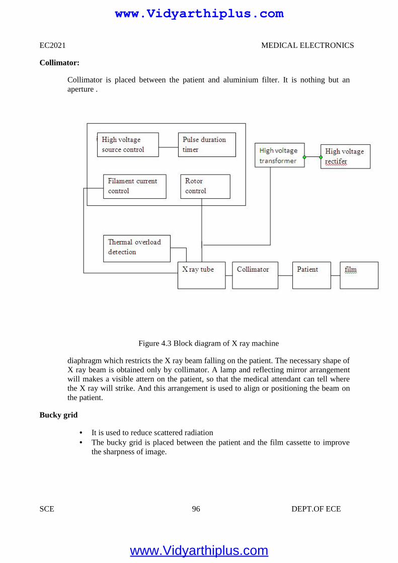
EC2021 MEDICAL ELECTRONICS
SCE 96 DEPT.OF ECE
Collimator:
Collimator is placed between the patient and aluminium filter. It is nothing but anaperture .
Figure 4.3 Block diagram of X ray machine
diaphragm which restricts the X ray beam falling on the patient. The necessary shape ofX ray beam is obtained only by collimator. A lamp and reflecting mirror arrangementwill makes a visible attern on the patient, so that the medical attendant can tell wherethe X ray will strike. And this arrangement is used to align or positioning the beam onthe patient.
Bucky grid
It is used to reduce scattered radiation The bucky grid is placed between the patient and the film cassette to improve
the sharpness of image.
www.Vidyarthiplus.com
www.Vidyarthiplus.com
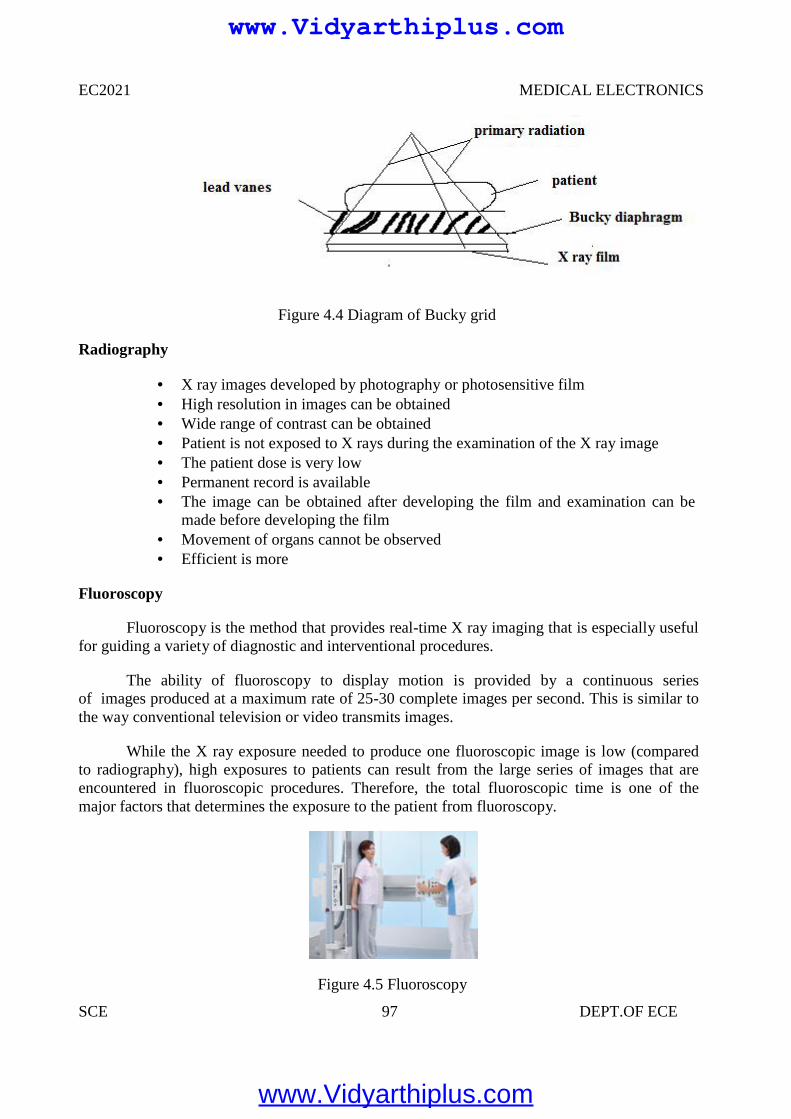
EC2021 MEDICAL ELECTRONICS
SCE 97 DEPT.OF ECE
Figure 4.4 Diagram of Bucky grid
Radiography
X ray images developed by photography or photosensitive film High resolution in images can be obtained Wide range of contrast can be obtained Patient is not exposed to X rays during the examination of the X ray image The patient dose is very low Permanent record is available The image can be obtained after developing the film and examination can be
made before developing the film Movement of organs cannot be observed Efficient is more
Fluoroscopy
Fluoroscopy is the method that provides real-time X ray imaging that is especially usefulfor guiding a variety of diagnostic and interventional procedures.
The ability of fluoroscopy to display motion is provided by a continuous seriesof images produced at a maximum rate of 25-30 complete images per second. This is similar tothe way conventional television or video transmits images.
While the X ray exposure needed to produce one fluoroscopic image is low (comparedto radiography), high exposures to patients can result from the large series of images that areencountered in fluoroscopic procedures. Therefore, the total fluoroscopic time is one of themajor factors that determines the exposure to the patient from fluoroscopy.
Figure 4.5 Fluoroscopy
www.Vidyarthiplus.com
www.Vidyarthiplus.com
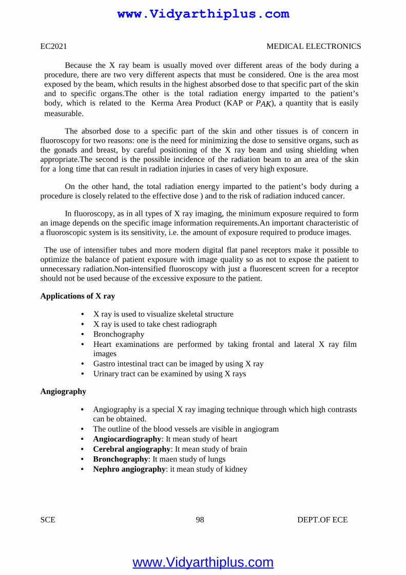
EC2021 MEDICAL ELECTRONICS
SCE 98 DEPT.OF ECE
Because the X ray beam is usually moved over different areas of the body during aprocedure, there are two very different aspects that must be considered. One is the area mostexposed by the beam, which results in the highest absorbed dose to that specific part of the skinand to specific organs.The other is the total radiation energy imparted to the patient’sbody, which is related to the Kerma Area Product (KAP or PAK), a quantity that is easilymeasurable.
The absorbed dose to a specific part of the skin and other tissues is of concern influoroscopy for two reasons: one is the need for minimizing the dose to sensitive organs, such asthe gonads and breast, by careful positioning of the X ray beam and using shielding whenappropriate.The second is the possible incidence of the radiation beam to an area of the skinfor a long time that can result in radiation injuries in cases of very high exposure.
On the other hand, the total radiation energy imparted to the patient’s body during aprocedure is closely related to the effective dose ) and to the risk of radiation induced cancer.
In fluoroscopy, as in all types of X ray imaging, the minimum exposure required to forman image depends on the specific image information requirements.An important characteristic ofa fluoroscopic system is its sensitivity, i.e. the amount of exposure required to produce images.
The use of intensifier tubes and more modern digital flat panel receptors make it possible tooptimize the balance of patient exposure with image quality so as not to expose the patient tounnecessary radiation.Non-intensified fluoroscopy with just a fluorescent screen for a receptorshould not be used because of the excessive exposure to the patient.
Applications of X ray
X ray is used to visualize skeletal structure X ray is used to take chest radiograph Bronchography Heart examinations are performed by taking frontal and lateral X ray film
images Gastro intestinal tract can be imaged by using X ray Urinary tract can be examined by using X rays
Angiography
Angiography is a special X ray imaging technique through which high contrastscan be obtained.
The outline of the blood vessels are visible in angiogram Angiocardiography: It mean study of heart Cerebral angiography: It mean study of brain Bronchography: It maen study of lungs Nephro angiography: it mean study of kidney
www.Vidyarthiplus.com
www.Vidyarthiplus.com
EC2021 MEDICAL ELECTRONICS
SCE 99 DEPT.OF ECE
4.3 USE OF RADIO ISOTOPE IN DIAGNOSIS
Nuclear medicine uses radiation to provide diagnostic information about thefunctioning of a person's specific organs, or to treat them. Diagnostic procedures are nowroutine.
Radiotherapy can be used to treat some medical conditions, especiallycancer, using radiation to weaken or destroy particular targeted cells.
Tens of millions of nuclear medicine procedures are performed each year, anddemand for radioisotopes is increasing rapidly.
Radiation is used to both detect and treat abnormalities in the body. We've alreadydiscussed the use of iodine-131 therapy for hyperthyroidism. Iodine-131 can also be usedin a diagnostic procedure to monitor the function of the thyroid.
The rate at which the thyroid rakes up the iodine-131 can be monitored with a scanningdevice to see if it is functioning properly.What makes radioisotopes so useful in diagnosticprocedures is that the body treats the tagged isotope in the same way that it treats thenonradioactive element.
Therefore, the tagged isotope goes right to the area of the body where you want it to go.For example, iodine, whether it's radioactive or not, goes right to the thyroid, where it isincorporated into the amino acid thyroxine (the only molecule in the body that containsiodine). Therefore, iodine-131 is perfect for monitoring the thyroid gland.
Chromium, in the form of sodium chromate, attaches strongly to the hemoglobin ofred blood cells. This makes radioactive chromium-151 an excellent isotope for determiningthe flow of blood through the heart. This isotope is also useful for determining the lifetime ofred blood cells, which can be of great importance in the diagnoses of anemias.
Radioactive cobalt (cobalt-59 or cobalt-60) is used to study defects in vitamin B12absorption. Cobalt is the metallic atom at the center of the B12 molecule. By injecting a patientwith vitamin B12, labeled with radioactive cobalt, the physician can study the path of thevitamin through the body and discover any irregularities.
One method is teletherapy, in which a high-energy beam of radiation is aimed at thecancerous tissues. A second method is brachytherapy, in which a radioactive isotope is placedinto the area to be treated. This is usually done by means of a seed, which could be a glass beadcontaining the isotope. In this way the isotope delivers a constant beam of radiation to theaffected area.
The third method is called radiopharmaceutical therapy. This method involves oral orintravenous administration of the isotope. The isotope then uses the normal body pathway toseek its target. This is the method that is used to get iodine-131 to the thyroid gland.
www.Vidyarthiplus.com
www.Vidyarthiplus.com
EC2021 MEDICAL ELECTRONICS
SCE 100 DEPT.OF ECE
A synthetic radioisotope is a radionuclide that is not found in nature: no natural processor mechanism exists which produces it, or it is so unstable that it decays away in a very shortperiod of time. Examples include technetium-95 and promethium-146. Many of these arefound in, and harvested from, spent nuclear fuel assemblies. Some must be manufacturedin particle accelerators.
Production
Some synthetic radioisotope are extracted from spent nuclear reactor fuel rods, whichcontain various fission products. For example, it is estimated that up to 1994, about 49,000 TBq(78 metric ton) of technetium was produced in nuclear reactors, which is by far the dominantsource of terrestrial technetium. However, only a fraction of the production is usedcommercially. Other synthetic isotopes are produced in significant quantities by fission but arenot yet being reclaimed. Other isotopes are manufactured by neutron irradiation of parentisotopes in a nuclear reactor (for example, Tc-97 can be made by neutron irradiation of Ru-96)or by bombarding parent isotopes with high energy particles from a particle accelerator.
Uses
Most synthetic radioisotopes are extremely radioactive and have a short half life.Though a health hazard, radioactive materials have many medical and industrial uses.
Nuclear medicine
The general field of nuclear medicine covers any use of radioisotopes for diagnosis ortreatment.
Diagnosis
Radioactive tracer compounds are used to observe the function of various organsand body systems. These compounds use a chemical tracer which is attracted to or concentratedby the activity which is being studied. That chemical tracer incorporates a short livedradioactive isotope, usually one which emits a gamma ray which is energetic enough to travelthrough the body and be captured outside by a gamma camera to map the concentrations.Gamma cameras and other similar detectors are highly efficient, and the tracer compounds aregenerally very effective at concentrating at the areas of interest, so the total amounts ofradioactive material needed are very small.The metastable nuclear isomer Tc-99m is a Gamma-emitter widely used for medical diagnostics because it has a short half-life of 6 hours, butcan be easily made in the hospital using a "technetium-cow".
Treatment
Radiopharmaceuticals are any of a number of compounds using a radioisotope formedical treatment, usually by bringing the radioactive isotope to a high concentration in thebody near a particular organ. For example, iodine-131 is used for treating some disorders andtumors of the thyroid gland.
www.Vidyarthiplus.com
www.Vidyarthiplus.com
EC2021 MEDICAL ELECTRONICS
SCE 101 DEPT.OF ECE
4.4 RADIATION THERAPY
Radiation therapy uses ionising radiation to treat cancer i.e. to destroy cancerous cells.There are two techniques in radiation therapy that are used to treat cancer using ionisingradiation:
• Radiotherapy• Brachytherapy
Radiation Therapy
Radiotherapy Treatment Planning
Every treatment using radiotherapy has to be rigorously planned. The planning process consistsof three phases:
• Planning• Simulation• Treatment
Planning
The cancerous tumour has to be located so that its size and position can be analysed. Thisinformation can be obtained from:
• X-rays• CT scans• MRI scans• Ultrasound images
Simulation
Once the amount of radiation to be given has been accurately calculated, the patient thengoes to the simulator to determine what settings are to be selected for the actual treatment using alinear accelerator. The settings are determined by taking a series of x-rays to make sure that thetumour is in the correct position ready to receive the ionising radiation.
Treatment
Cancerous tumours can be treated using radiotherapy as follows:• Irradiation using high energy gamma rays.• Irradiation using high energy x-rays.
Irradiation Using High Energy Gamma Rays• Gamma rays are emitted from a cobalt-60 source – a radioactive form of cobalt.• The cobalt source is kept within a thick, heavy metal container.• This container has a slit in it to allow a narrow beam of gamma rays to emerge.
www.Vidyarthiplus.com
www.Vidyarthiplus.com
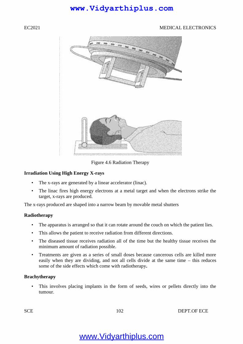
EC2021 MEDICAL ELECTRONICS
SCE 102 DEPT.OF ECE
Figure 4.6 Radiation Therapy
Irradiation Using High Energy X-rays
• The x-rays are generated by a linear accelerator (linac).
• The linac fires high energy electrons at a metal target and when the electrons strike thetarget, x-rays are produced.
The x-rays produced are shaped into a narrow beam by movable metal shutters
Radiotherapy
• The apparatus is arranged so that it can rotate around the couch on which the patient lies.
• This allows the patient to receive radiation from different directions.
• The diseased tissue receives radiation all of the time but the healthy tissue receives theminimum amount of radiation possible.
• Treatments are given as a series of small doses because cancerous cells are killed moreeasily when they are dividing, and not all cells divide at the same time – this reducessome of the side effects which come with radiotherapy.
Brachytherapy
• This involves placing implants in the form of seeds, wires or pellets directly into thetumour.
www.Vidyarthiplus.com
www.Vidyarthiplus.com
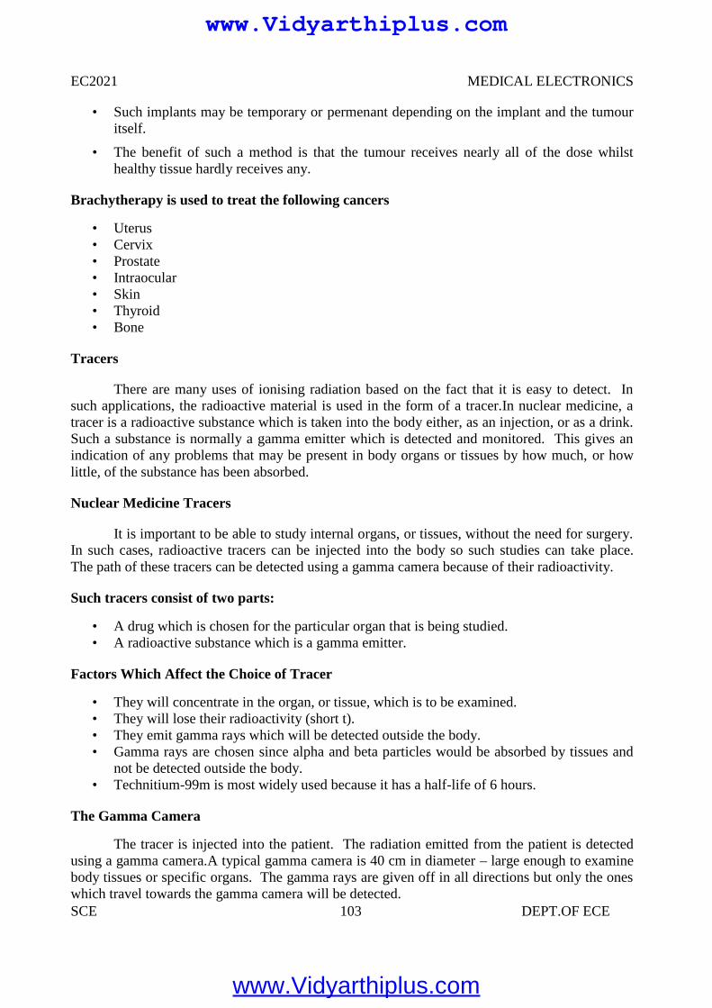
EC2021 MEDICAL ELECTRONICS
SCE 103 DEPT.OF ECE
• Such implants may be temporary or permenant depending on the implant and the tumouritself.
• The benefit of such a method is that the tumour receives nearly all of the dose whilsthealthy tissue hardly receives any.
Brachytherapy is used to treat the following cancers
• Uterus• Cervix• Prostate• Intraocular• Skin• Thyroid• Bone
Tracers
There are many uses of ionising radiation based on the fact that it is easy to detect. Insuch applications, the radioactive material is used in the form of a tracer.In nuclear medicine, atracer is a radioactive substance which is taken into the body either, as an injection, or as a drink.Such a substance is normally a gamma emitter which is detected and monitored. This gives anindication of any problems that may be present in body organs or tissues by how much, or howlittle, of the substance has been absorbed.
Nuclear Medicine Tracers
It is important to be able to study internal organs, or tissues, without the need for surgery.In such cases, radioactive tracers can be injected into the body so such studies can take place.The path of these tracers can be detected using a gamma camera because of their radioactivity.
Such tracers consist of two parts:
• A drug which is chosen for the particular organ that is being studied.• A radioactive substance which is a gamma emitter.
Factors Which Affect the Choice of Tracer
• They will concentrate in the organ, or tissue, which is to be examined.• They will lose their radioactivity (short t).• They emit gamma rays which will be detected outside the body.• Gamma rays are chosen since alpha and beta particles would be absorbed by tissues and
not be detected outside the body.• Technitium-99m is most widely used because it has a half-life of 6 hours.
The Gamma Camera
The tracer is injected into the patient. The radiation emitted from the patient is detectedusing a gamma camera.A typical gamma camera is 40 cm in diameter – large enough to examinebody tissues or specific organs. The gamma rays are given off in all directions but only the oneswhich travel towards the gamma camera will be detected.
www.Vidyarthiplus.com
www.Vidyarthiplus.com
EC2021 MEDICAL ELECTRONICS
SCE 104 DEPT.OF ECE
A gamma camera consists of three main parts:• A collimator.• A detector.• Electronic systems.
The Collimator
• The collimator is usually made of lead and it contains thousands of tiny holes.• Only gamma rays which travel through the holes in the collimator will be detected.
The Detector• The detector is a scintillation crystal and is usually made of Sodium Iodide with traces of
Thallium added.• The detector is a scintillation crystal and it converts the gamma rays that reach it into light
energy.
The Electronic Systems• The electronic systems detect the light energy received from the detector and converts it
into electrical signals.
Diagnosis Static Imaging• There is a time delay between injecting the tracer and the build-up of radiation in the
organ.
Static studies are performed on the brain, bone or lungs scans
Dynamic Imaging
• The amount of radioactive build-up is measured over time.• Dynamic studies are performed on the kidneys and heart.• Renograms are dynamic images of the kidneys and they are performed for the following
reasons:• To assess individual kidney and/or bladder function.• To detect urinary tract infections.• To detect and assess obstructed kidney(s).• To detect and assess vesico-ureteric reflux.• To assess kidney transplant(s).
Performing the Renogram
• The tracer is injected into the patient.• The radioactive material is removed from the bloodstream by the kidneys.• Within a few minutes of the injection, the radiation is concentrated in the kidneys.• After 10 – 15 minutes, almost all of the radiation should be in the bladder.• The gamma camera takes readings every few seconds for 20 minutes.
The Renogram
• The computer adds up the radioactivity in each kidney and the bladder.• This can be shown as a graph of activity versus time – a time-activity curve.
www.Vidyarthiplus.com
www.Vidyarthiplus.com
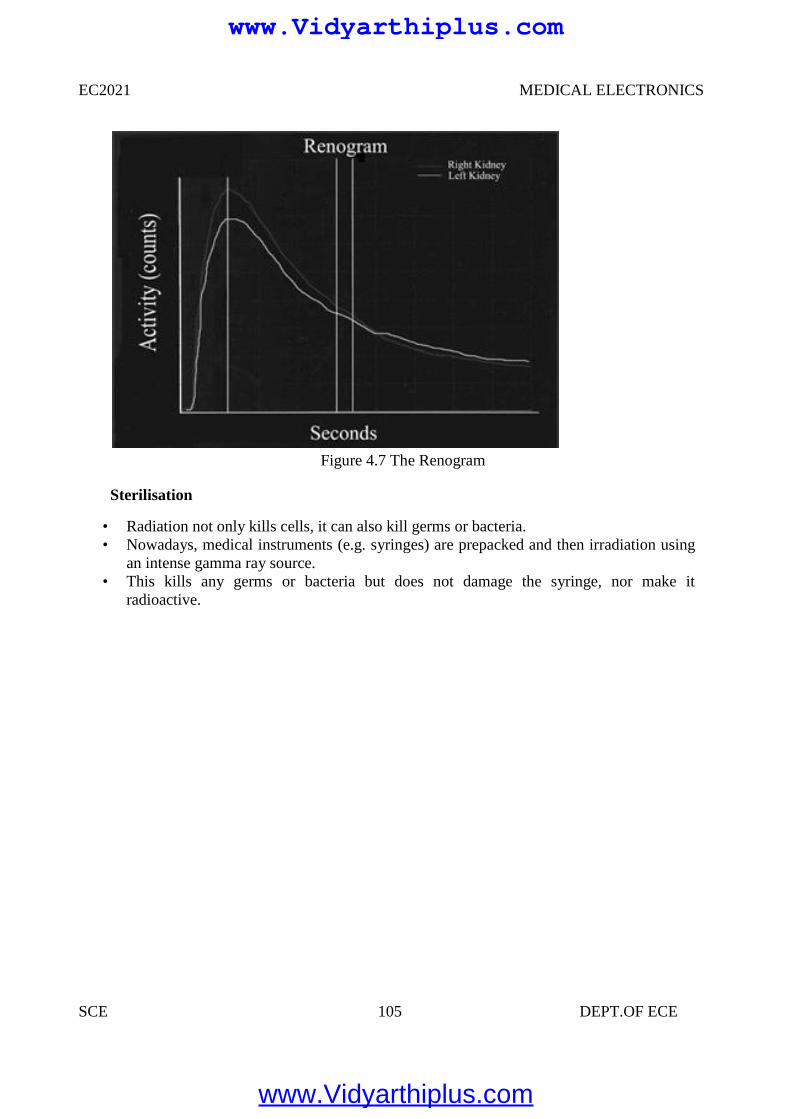
EC2021 MEDICAL ELECTRONICS
SCE 105 DEPT.OF ECE
Figure 4.7 The Renogram
Sterilisation
• Radiation not only kills cells, it can also kill germs or bacteria.• Nowadays, medical instruments (e.g. syringes) are prepacked and then irradiation using
an intense gamma ray source.• This kills any germs or bacteria but does not damage the syringe, nor make it
radioactive.
www.Vidyarthiplus.com
www.Vidyarthiplus.com
EC2021 MEDICAL ELECTRONICS
SCE 106 DEPT.OF ECE
UNIT V
RECENT TRENDS IN MEDICAL INSRUMENTATION
5.1 THERMOGRAPHY
Thermograph, thermal imaging, or thermal video, is a type of infrared imaging. Thermographic cameras detect radiation in the infrared range of the electromagnetic spectrum (roughly900–14,000 nanometers or 0.9–14 µm) and produce images of that radiation. Since infraredradiation is emitted by all objects based on their temperatures, according to the black bodyradiation law, thermograph makes it possible to see one's environment with or without visibleillumination.
The amount of radiation emitted by an object increases with temperature, thereforethermograph allows one to see variations in temperature (hence the name). When viewed bythermo graphic camera, warm objects stand out well against cooler backgrounds; humans andother warm-blooded animals become easily visible against the environment, day or night. As aresult, thermograph’s extensive use can historically be ascribed to the military and securityservices. Thermal imaging photography finds many other uses. For example, firefighters use it tosee through smoke, find persons, and localize the base of a fire.
With thermal imaging, power lines maintenance technicians locate overheating joints andparts, a telltale sign of their failure, to eliminate potential hazards. Where thermal insulationbecomes faulty, building construction technicians can see heat leaks to improve the efficiencies ofcooling or heating air-conditioning.
Thermal imaging cameras are also installed in some luxury cars to aid the driver, the firstbeing the 2000 Cadillac Deville. Some physiological activities, particularly responses, in humanbeings and other warm-blooded animals can also be monitored with thermo graphic imaging. Theappearance and operation of a modern thermo graphic camera is often similar to a camcorder.Enabling the user to see in the infrared spectrum is a function so useful that ability to record theiroutput is often optional. A recording module is therefore not always built-in.Instead of CCDsensors, most thermal imaging cameras use CMOS Focal Plane Array (FPA). The most commontypes are InSb, InGaAs, HgCdTe and QWIP FPA.
The newest technologies are using low cost and uncooled microbolometers FPA sensors.Their resolution is considerably lower than of optical cameras, mostly 160x120 or 320x240pixels, up to 640x512 for the most expensive models. Thermo graphic cameras are much moreexpensive than their visible-spectrum counterparts, and higher-end models are often export-restricted. Older bolometer or more sensitive models as require cryogenic cooling, usually by aminiature Stirling cycle refrigerator or liquid nitrogen.
www.Vidyarthiplus.com
www.Vidyarthiplus.com
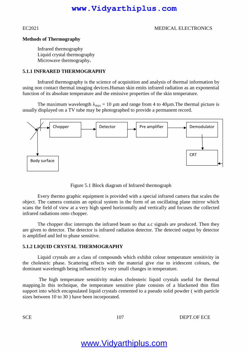
EC2021 MEDICAL ELECTRONICS
SCE 107 DEPT.OF ECE
Methods of Thermography
Infrared thermographyLiquid crystal thermographyMicrowave thermography.
5.1.1 INFRARED THERMOGRAPHY
Infrared thermography is the science of acquisition and analysis of thermal information byusing non contact thermal imaging devices.Human skin emits infrared radiation as an exponentialfunction of its absolute temperature and the emissive properties of the skin temperature.
The maximum wavelength λmax = 10 µm and range from 4 to 40µm.The thermal picture isusually displayed on a TV tube may be photographed to provide a permanent record.
Figure 5.1 Block diagram of Infrared thermograph
Every thermo graphic equipment is provided with a special infrared camera that scales theobject. The camera contains an optical system in the form of an oscillating plane mirror whichscans the field of view at a very high speed horizontally and vertically and focuses the collectedinfrared radiations onto chopper.
The chopper disc interrupts the infrared beam so that a.c signals are produced. Then theyare given to detector. The detector is infrared radiation detector. The detected output by detectoris amplified and led to phase sensitive.
5.1.2 LIQUID CRYSTAL THERMOGRAPHY
Liquid crystals are a class of compounds which exhibit colour temperature sensitivity inthe cholestric phase. Scattering effects with the material give rise to iridescent colours, thedominant wavelength being influenced by very small changes in temperature.
The high temperature sensitivity makes cholesteric liquid crystals useful for thermalmapping.In this technique, the temperature sensitive plate consists of a blackened thin flimsupport into which encapsulated liquid crystals cemented to a pseudo solid powder ( with particlesizes between 10 to 30 ) have been incorporated.
Chopper
Body surfaceCRT
Detector Pre amplifier Demodulator
www.Vidyarthiplus.com
www.Vidyarthiplus.com
EC2021 MEDICAL ELECTRONICS
SCE 108 DEPT.OF ECE
Thermal contact between the skin surface and plate produces a color change in theencapsulated liquid crystals; red for relatively low temperatures through the visual spectrum toviolet for high temperatures. But in infrared thermograms, the violet colour is used to identify thelow temperature regions and the bright colour or red is used to identify the temperature regions.
If we want to study a breast’s temperature distribution, several different plates arenecessary to cover a breast temperature range from 280C to360C. Each plate covers a range oftemperature 30C. A record of the liquid crystal image may be obtained by colour photography.The response time varies according to the thickness of plate ( ranges from 0.06mm to 0.3 mm)and is 20 to 40 seconds.
5.1.3 MICROWAVE THERMOGRAPHY
Eventhough we get microwave emissions from the skin surface, that intensity is verysmall when we compare with Infra red radiation intensity . (10 wavelenght emission intensity is108 times greater than 10 cm wavelength emission intensity). But using modern microwaveradiometers one can detect temperature change of 0.1K. since body tissues are partiallytransparent to microwave radiations which orginates from a tissue volume extending from theskin surface to a depth of several centimeters. Microwave radiometers consisting of matchedantennae placed in contact with the skin surface for use at 1.3 G Hz and 3.3 G Hz have been usedto sense subcutaneous temperature.
The present day thermographic systems, using Infrared radiation, only give a temperaturemap of the skin due to low penetration depth of the short wavelength of the infrared component ofthe emitted radiation. Using a microwave receiver with a frequency response from 1.7 GHz to 2.5GHz a penetration depth of 1 cm in tissue and 8 cm in fat and bone can be obtained.
A severe problem is the unknown emissivity of the body surface for microwaves, as partof the radiation is reflected back into the body.In a conventional radiometer this gives rise toameasurement error proportional to the temperature difference between the body surface and theapplied antenna. This error lies in the order of 1-2 K which is too high for medical applications.
The problem has been solved iv an elegant way by adding artificial microwave noise fromthe antenna,thus providing a radiation balace between the receiver and body surface. With this atemperature sensitivity of 0.1 K could be obtained. Based on the transducer attachment on theskin surface, we can classify the thermography into contact thermography and tele-thermography.
Advantages of Thermography
Get a visual picture so that you can compare temperatures over a large areaIt is real time capable of catching moving targetsAble to find deteriorating components prior to failureMeasurement in areas inaccessible or hazardous for other methodsIt is a non-destructive test method
www.Vidyarthiplus.com
www.Vidyarthiplus.com
EC2021 MEDICAL ELECTRONICS
SCE 109 DEPT.OF ECE
Limitations & disadvantages of thermography
Quality cameras are expensive and are easily damagedImages can be hard to interpret accurately even with experienceAccurate temperature measurements are very hard to make because of emissivitiesMost cameras have ±2% or worse accuracy (not as accurate as contact)Training and staying proficient in IR scanning is time consumingAbility to only measure surface areas
Applications
Healthy CasesTumorsInflammationDiseases of peripheral VesselsBurns and PernionesSkin Grafts and Organ TransplantationCollagen diseasesOrthopedic DiseasesBrain and Nervous DiseasesHarmone DiseasesExamination of Placenta Attachment
5.2 ENDOSCOPY UNIT
HISTORY
The first endoscope, of a kind, was developed in 1806 by Philip Bozzini with hisintroduction of a Lichtleiter (light conductor) for the examinations of the canals and cavities ofthe human body. However, the Vienna Medical Society disapproved of such curiosity. Anendoscope was first introduced into a human in 1822 by William Beaumont, an army surgeon atMackinac Island, MichiganThe use of electric light was a major step in the improvement ofendoscopy. The first such lights were external. Later, smaller bulbs became available makinginternal light possible, for instance in a hysteroscope by Charles David in 1908Hans ChristianJacobaeus has been given credit for early endoscopic explorations of the abdomen and the thoraxwith laparoscopy (1912) and thoracoscopy (1910).Laparoscopy was used in the diagnosis of liverand gallbladder disease by Heinz Kalk in the 1930. Hope reported in 1937 on the use oflaparoscopy to diagnose ectopic pregnancyIn 1944, Raoul Palmer placed his patients in theTrendelenburg position after gaseous distention of the abdomen and thus was able to reliablyperform gynecologic laparoscopy
The first gastrocamera was released in 1950 by Olympus Optical Co., Ltd. The devicetook pictures on monochromatic film using a small light bulb that was triggered manually. Thedevice was of limited use, however, because it did not implement real-time optical capability.Olympus continued its development of endoscopes by incorporating fiber optics in the early1960s, leading to the first useful endoscopes. In 1964, it released a gastrocamera guided by a
www.Vidyarthiplus.com
www.Vidyarthiplus.com
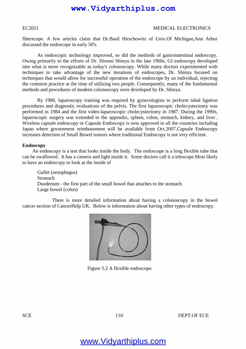
EC2021 MEDICAL ELECTRONICS
SCE 110 DEPT.OF ECE
fiberscope. A few articles claim that Dr.Basil Hirschowitz of Univ.Of Michigan,Ann Arbordiscussed the endoscope in early 50's.
As endoscopic technology improved, so did the methods of gastrointestinal endoscopy.Owing primarily to the efforts of Dr. Hiromi Shinya in the late 1960s, GI endoscopy developedinto what is more recognizable as today's colonoscopy. While many doctors experimented withtechniques to take advantage of the new iterations of endoscopes, Dr. Shinya focused ontechniques that would allow for successful operation of the endoscope by an individual, rejectingthe common practice at the time of utilizing two people. Consequently, many of the fundamentalmethods and procedures of modern colonoscopy were developed by Dr. Shinya.
By 1980, laparoscopy training was required by gynecologists to perform tubal ligationprocedures and diagnostic evaluations of the pelvis. The first laparoscopic cholecystectomy wasperformed in 1984 and the first video-laparoscopic cholecystectomy in 1987. During the 1990s,laparoscopic surgery was extended to the appendix, spleen, colon, stomach, kidney, and liver .Wireless capsule endoscopy or Capsule Endoscopy is now approved in all the countries includingJapan where government reimbusement will be available from Oct.2007.Capsule Endoscopyincreases detection of Small Bowel tumors where traditional Endoscopy is not very efficient.
EndoscopyAn endoscopy is a test that looks inside the body. The endoscope is a long flexible tube that
can be swallowed. It has a camera and light inside it. Some doctors call it a telescope.Most likelyto have an endoscopy to look at the inside of
Gullet (oesophagus)StomachDuodenum - the first part of the small bowel that attaches to the stomachLarge bowel (colon)
There is more detailed information about having a colonoscopy in the bowelcancer section of CancerHelp UK. Below is information about having other types of endoscopy.
Figure 5.2 A flexible endoscope.
www.Vidyarthiplus.com
www.Vidyarthiplus.com
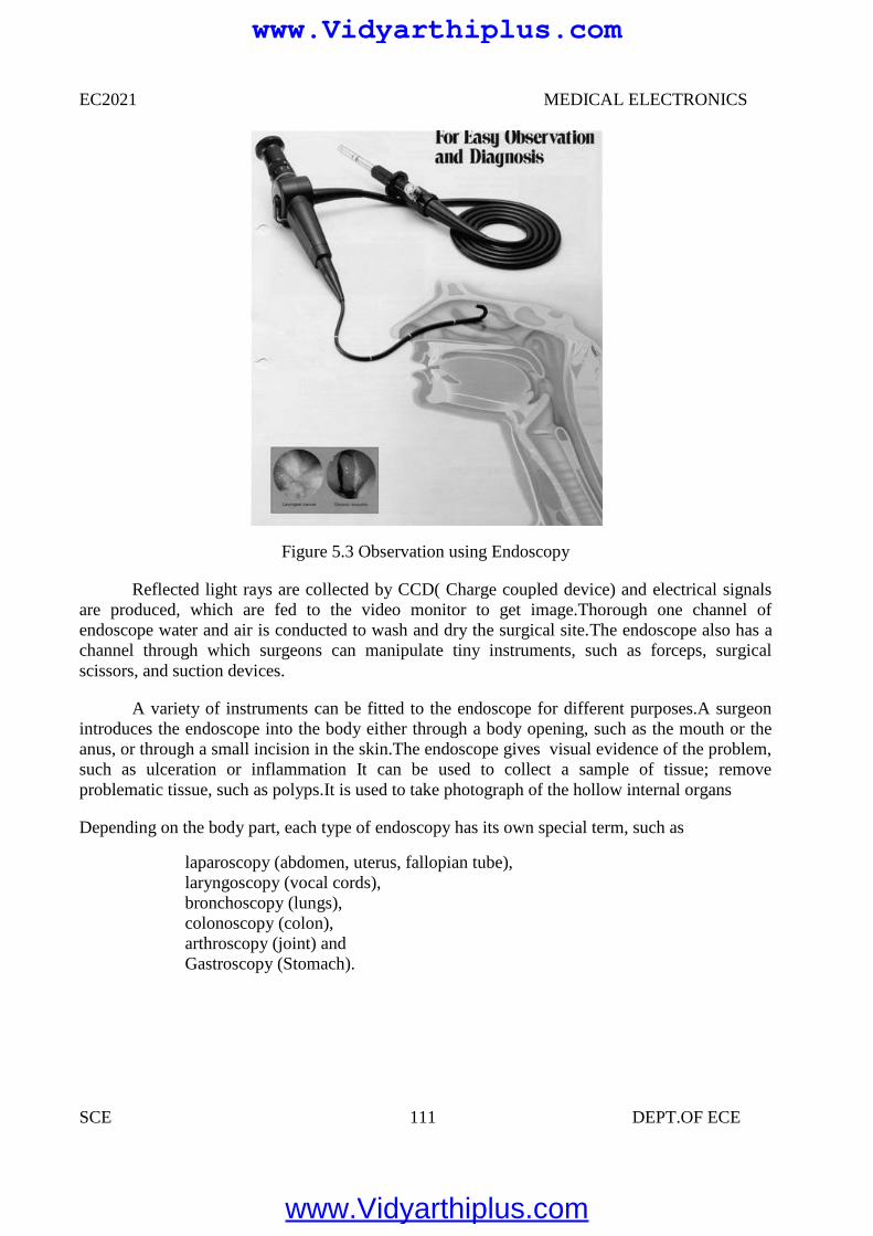
EC2021 MEDICAL ELECTRONICS
SCE 111 DEPT.OF ECE
Figure 5.3 Observation using Endoscopy
Reflected light rays are collected by CCD( Charge coupled device) and electrical signalsare produced, which are fed to the video monitor to get image.Thorough one channel ofendoscope water and air is conducted to wash and dry the surgical site.The endoscope also has achannel through which surgeons can manipulate tiny instruments, such as forceps, surgicalscissors, and suction devices.
A variety of instruments can be fitted to the endoscope for different purposes.A surgeonintroduces the endoscope into the body either through a body opening, such as the mouth or theanus, or through a small incision in the skin.The endoscope gives visual evidence of the problem,such as ulceration or inflammation It can be used to collect a sample of tissue; removeproblematic tissue, such as polyps.It is used to take photograph of the hollow internal organs
Depending on the body part, each type of endoscopy has its own special term, such as
laparoscopy (abdomen, uterus, fallopian tube),laryngoscopy (vocal cords),bronchoscopy (lungs),colonoscopy (colon),arthroscopy (joint) andGastroscopy (Stomach).
www.Vidyarthiplus.com
www.Vidyarthiplus.com
EC2021 MEDICAL ELECTRONICS
SCE 112 DEPT.OF ECE
Components
An endoscope can consist of
A rigid or flexible tube A light delivery system to illuminate the organ or object under inspection. The light
source is normally outside the body and the light is typically directed via an optical fibersystem A lens system transmitting the image to the viewer from the fiberscope
An additional channel to allow entry of medical instruments or manipulators
Uses
Endoscopy can involveThe gastrointestinal tract (GI tract):esophagus, stomach and duodenum (esophagogastroduodenoscopy)small intestinecolon (colonoscopy,proctosigmoidoscopy)Bile duct
The respiratory tract The nose (rhinoscopy) The lower respiratory tract (bronchoscopy) The urinary tract (cystoscopy) The female reproductive system The cervix (colposcopy) The uterus (hysteroscopy) The Fallopian tubes (Falloscopy) Normally closed body cavities (through a small incision): The abdominal or pelvic cavity (laparoscopy) The interior of a joint (arthroscopy) Organs of the chest (thoracoscopy and mediastinoscopy) During pregnancy The amnion (amnioscopy) The fetus (fetoscopy) Plastic Surgery Panendoscopy (or triple endoscopy) Combines laryngoscopy, esophagoscopy, and bronchoscopy
Non-medical uses for endoscopy
The planning and architectural community have found the endoscope useful for pre-visualization of scale models of proposed buildings and cities (architectural endoscopy) Internalinspection of complex technical systems (borescope) Endoscopes are also a tool helpful in theexamination of improvised explosive devices by bomb disposal personnel. The FBI usesendoscopes for conducting surveillance via tight spaces.
www.Vidyarthiplus.com
www.Vidyarthiplus.com
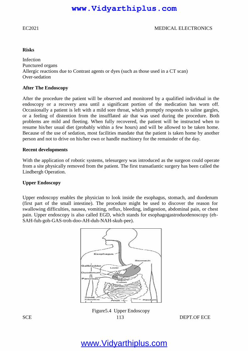
EC2021 MEDICAL ELECTRONICS
SCE 113 DEPT.OF ECE
Risks
InfectionPunctured organsAllergic reactions due to Contrast agents or dyes (such as those used in a CT scan)Over-sedation
After The Endoscopy
After the procedure the patient will be observed and monitored by a qualified individual in theendoscopy or a recovery area until a significant portion of the medication has worn off.Occasionally a patient is left with a mild sore throat, which promptly responds to saline gargles,or a feeling of distention from the insufflated air that was used during the procedure. Bothproblems are mild and fleeting. When fully recovered, the patient will be instructed when toresume his/her usual diet (probably within a few hours) and will be allowed to be taken home.Because of the use of sedation, most facilities mandate that the patient is taken home by anotherperson and not to drive on his/her own or handle machinery for the remainder of the day.
Recent developments
With the application of robotic systems, telesurgery was introduced as the surgeon could operatefrom a site physically removed from the patient. The first transatlantic surgery has been called theLindbergh Operation.
Upper Endoscopy
Upper endoscopy enables the physician to look inside the esophagus, stomach, and duodenum(first part of the small intestine). The procedure might be used to discover the reason forswallowing difficulties, nausea, vomiting, reflux, bleeding, indigestion, abdominal pain, or chestpain. Upper endoscopy is also called EGD, which stands for esophagogastroduodenoscopy (eh-SAH-fuh-goh-GAS-troh-doo-AH-duh-NAH-skuh-pee).
Figure5.4 Upper Endoscopy
www.Vidyarthiplus.com
www.Vidyarthiplus.com
EC2021 MEDICAL ELECTRONICS
SCE 114 DEPT.OF ECE
For the procedure you will swallow a thin, flexible, lighted tube called an endoscope (EN-doh-skope). Right before the procedure the physician will spray your throat with a numbing agentthat may help prevent gagging. You may also receive pain medicine and a sedative to help yourelax during the exam. The endoscope transmits an image of the inside of the esophagus, stomach,and duodenum, so the physician can carefully examine the lining of these organs. The scope alsoblows air into the stomach; this expands the folds of tissue and makes it easier for the physician toexamine the stomach.
The physician can see abnormalities, like inflammation or bleeding, through theendoscope that don't show up well on x rays. The physician can also insert instruments into thescope to treat bleeding abnormalities or remove samples of tissue (biopsy) for furthertests.Possible complications of upper endoscopy include bleeding and puncture of the stomachlining. However, such complications are rare. Most people will probably have nothing more thana mild sore throat after the procedure.The procedure takes 20 to 30 minutes. Because you will besedated, you will need to rest at the endoscopy facility for 1 to 2 hours until the medication wearsoff.
Preparation
Stomach and duodenum must be empty for the procedure to be thorough and safe, will notbe able to eat or drink anything for at least 6 hours beforehand. Also, must arrange for someone totake home—will not be allowed to drive because of the sedatives. Physician may give otherspecial instructions.
Need of Endoscopy
Endoscopy allows physicians to peer through the body's passageways. Endoscopy is theexamination and inspection of the interior of body organs, joints or cavities through anendoscope. An endoscope is a device that uses fiber optics and powerful lens systems to providelighting and visualization of the interior of a joint. The portion of the endoscope inserted into thebody may be rigid or flexible, depending upon the medical procedure.
An endoscope uses two fiber optic lines. A "light fiber" carries light into the body cavityand an "image fiber" carries the image of the body cavity back to the physician's viewing lens.There is also a separate port to allow for administration of drugs, suction, and irrigation. This portmay also be used to introduce small folding instruments such as forceps, scissors, brushes, snaresand baskets for tissue excision (removal), sampling, or other diagnostic and therapeutic work.Endoscopes may be used in conjunction with a camera or video recorder to document images ofthe inside of the joint or chronicle an endoscopic procedure. New endoscopes have digitalcapabilities for manipulating and enhancing the video images.
www.Vidyarthiplus.com
www.Vidyarthiplus.com
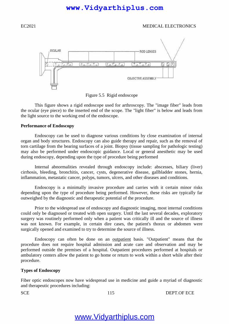
EC2021 MEDICAL ELECTRONICS
SCE 115 DEPT.OF ECE
Figure 5.5 Rigid endoscope
This figure shows a rigid endoscope used for arthroscopy. The "image fiber" leads fromthe ocular (eye piece) to the inserted end of the scope. The "light fiber" is below and leads fromthe light source to the working end of the endoscope.
Performance of Endoscopy
Endoscopy can be used to diagnose various conditions by close examination of internalorgan and body structures. Endoscopy can also guide therapy and repair, such as the removal oftorn cartilage from the bearing surfaces of a joint. Biopsy (tissue sampling for pathologic testing)may also be performed under endoscopic guidance. Local or general anesthetic may be usedduring endoscopy, depending upon the type of procedure being performed
Internal abnormalities revealed through endoscopy include: abscesses, biliary (liver)cirrhosis, bleeding, bronchitis, cancer, cysts, degenerative disease, gallbladder stones, hernia,inflammation, metastatic cancer, polyps, tumors, ulcers, and other diseases and conditions.
Endoscopy is a minimally invasive procedure and carries with it certain minor risksdepending upon the type of procedure being performed. However, these risks are typically faroutweighed by the diagnostic and therapeutic potential of the procedure.
Prior to the widespread use of endoscopy and diagnostic imaging, most internal conditionscould only be diagnosed or treated with open surgery. Until the last several decades, exploratorysurgery was routinely performed only when a patient was critically ill and the source of illnesswas not known. For example, in certain dire cases, the patient's thorax or abdomen weresurgically opened and examined to try to determine the source of illness.
Endoscopy can often be done on an outpatient basis. "Outpatient" means that theprocedure does not require hospital admission and acute care and observation and may beperformed outside the premises of a hospital. Outpatient procedures performed at hospitals orambulatory centers allow the patient to go home or return to work within a short while after theirprocedure.
Types of Endoscopy
Fiber optic endoscopes now have widespread use in medicine and guide a myriad of diagnosticand therapeutic procedures including:
www.Vidyarthiplus.com
www.Vidyarthiplus.com
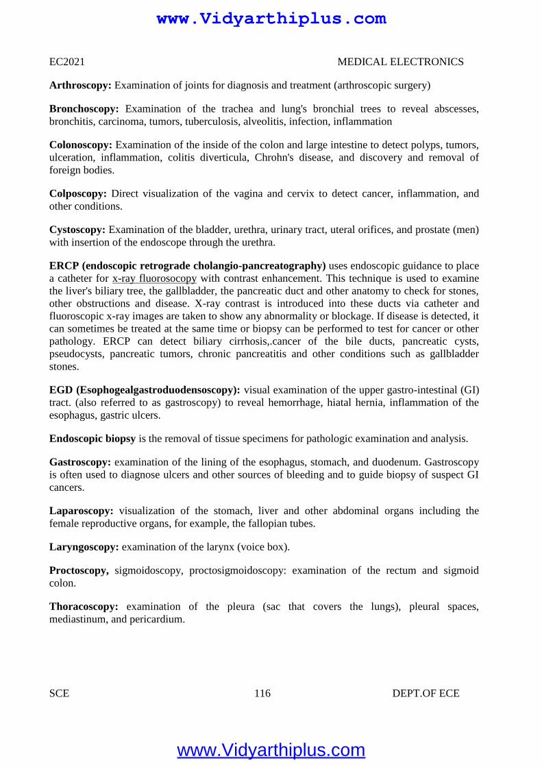
EC2021 MEDICAL ELECTRONICS
SCE 116 DEPT.OF ECE
Arthroscopy: Examination of joints for diagnosis and treatment (arthroscopic surgery)
Bronchoscopy: Examination of the trachea and lung's bronchial trees to reveal abscesses,bronchitis, carcinoma, tumors, tuberculosis, alveolitis, infection, inflammation
Colonoscopy: Examination of the inside of the colon and large intestine to detect polyps, tumors,ulceration, inflammation, colitis diverticula, Chrohn's disease, and discovery and removal offoreign bodies.
Colposcopy: Direct visualization of the vagina and cervix to detect cancer, inflammation, andother conditions.
Cystoscopy: Examination of the bladder, urethra, urinary tract, uteral orifices, and prostate (men)with insertion of the endoscope through the urethra.
ERCP (endoscopic retrograde cholangio-pancreatography) uses endoscopic guidance to placea catheter for x-ray fluorosocopy with contrast enhancement. This technique is used to examinethe liver's biliary tree, the gallbladder, the pancreatic duct and other anatomy to check for stones,other obstructions and disease. X-ray contrast is introduced into these ducts via catheter andfluoroscopic x-ray images are taken to show any abnormality or blockage. If disease is detected, itcan sometimes be treated at the same time or biopsy can be performed to test for cancer or otherpathology. ERCP can detect biliary cirrhosis,.cancer of the bile ducts, pancreatic cysts,pseudocysts, pancreatic tumors, chronic pancreatitis and other conditions such as gallbladderstones.
EGD (Esophogealgastroduodensoscopy): visual examination of the upper gastro-intestinal (GI)tract. (also referred to as gastroscopy) to reveal hemorrhage, hiatal hernia, inflammation of theesophagus, gastric ulcers.
Endoscopic biopsy is the removal of tissue specimens for pathologic examination and analysis.
Gastroscopy: examination of the lining of the esophagus, stomach, and duodenum. Gastroscopyis often used to diagnose ulcers and other sources of bleeding and to guide biopsy of suspect GIcancers.
Laparoscopy: visualization of the stomach, liver and other abdominal organs including thefemale reproductive organs, for example, the fallopian tubes.
Laryngoscopy: examination of the larynx (voice box).
Proctoscopy, sigmoidoscopy, proctosigmoidoscopy: examination of the rectum and sigmoidcolon.
Thoracoscopy: examination of the pleura (sac that covers the lungs), pleural spaces,mediastinum, and pericardium.
www.Vidyarthiplus.com
www.Vidyarthiplus.com
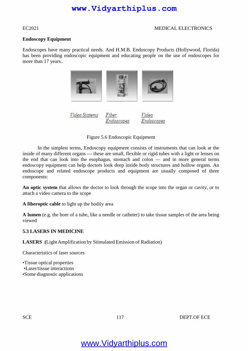
EC2021 MEDICAL ELECTRONICS
SCE 117 DEPT.OF ECE
Endoscopy Equipment
Endoscopes have many practical needs. And H.M.B. Endoscopy Products (Hollywood, Florida)has been providing endoscopic equipment and educating people on the use of endoscopes formore than 17 years..
Figure 5.6 Endoscopic Equipment
In the simplest terms, Endoscopy equipment consists of instruments that can look at theinside of many different organs — these are small, flexible or rigid tubes with a light or lenses onthe end that can look into the esophagus, stomach and colon — and in more general termsendoscopy equipment can help doctors look deep inside body structures and hollow organs. Anendoscope and related endoscope products and equipment are usually composed of threecomponents:
An optic system that allows the doctor to look through the scope into the organ or cavity, or toattach a video camera to the scope
A fiberoptic cable to light up the bodily area
A lumen (e.g. the bore of a tube, like a needle or catheter) to take tissue samples of the area beingviewed
5.3 LASERS IN MEDICINE
LASERS (Light Amplification by Stimulated Emission of Radiation)
Characteristics of laser sources
•Tissue optical properties•Laser/tissue interactions•Some diagnostic applications
www.Vidyarthiplus.com
www.Vidyarthiplus.com
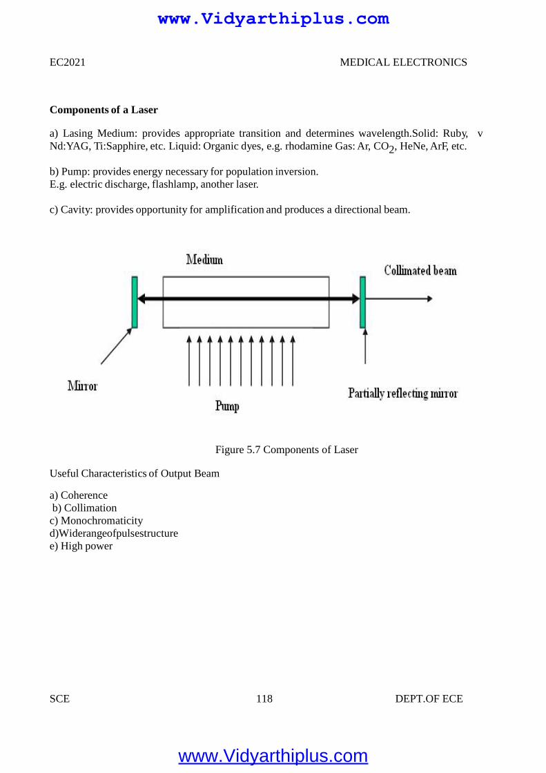
EC2021 MEDICAL ELECTRONICS
SCE 118 DEPT.OF ECE
Components of a Laser
a) Lasing Medium: provides appropriate transition and determines wavelength.Solid: Ruby, vNd:YAG, Ti:Sapphire, etc. Liquid: Organic dyes, e.g. rhodamine Gas: Ar, CO2, HeNe, ArF, etc.
b) Pump: provides energy necessary for population inversion.E.g. electric discharge, flashlamp, another laser.
c) Cavity: provides opportunity for amplification and produces a directional beam.
Figure 5.7 Components of Laser
Useful Characteristics of Output Beam
a) Coherenceb) Collimationc) Monochromaticityd)Widerangeofpulsestructuree) High power
www.Vidyarthiplus.com
www.Vidyarthiplus.com
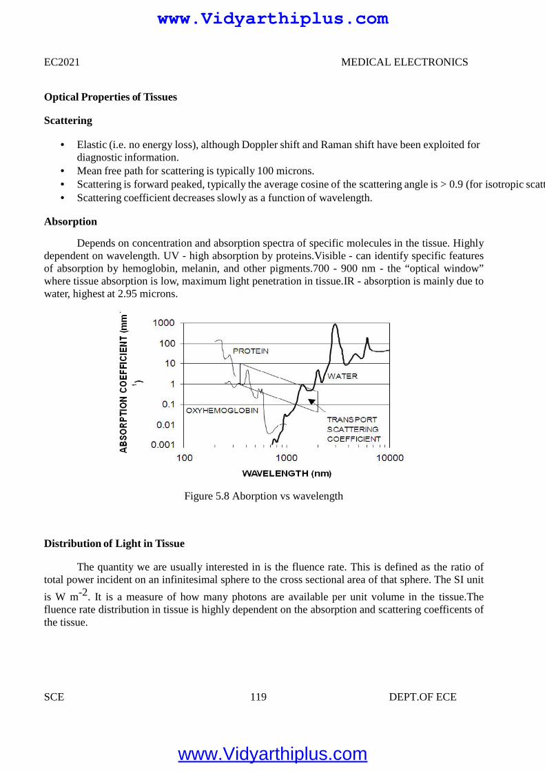
EC2021 MEDICAL ELECTRONICS
SCE 119 DEPT.OF ECE
Optical Properties of Tissues
Scattering
Elastic (i.e. no energy loss), although Doppler shift and Raman shift have been exploited fordiagnostic information.
Mean free path for scattering is typically 100 microns. Scattering is forward peaked, typically the average cosine of the scattering angle is > 0.9 (for isotropic scattering it is zero.) Scattering coefficient decreases slowly as a function of wavelength.
Absorption
Depends on concentration and absorption spectra of specific molecules in the tissue. Highlydependent on wavelength. UV - high absorption by proteins.Visible - can identify specific featuresof absorption by hemoglobin, melanin, and other pigments.700 - 900 nm - the “optical window”where tissue absorption is low, maximum light penetration in tissue.IR - absorption is mainly due towater, highest at 2.95 microns.
Figure 5.8 Aborption vs wavelength
Distribution of Light in Tissue
The quantity we are usually interested in is the fluence rate. This is defined as the ratio oftotal power incident on an infinitesimal sphere to the cross sectional area of that sphere. The SI unit
is W m-2. It is a measure of how many photons are available per unit volume in the tissue.Thefluence rate distribution in tissue is highly dependent on the absorption and scattering coefficents ofthe tissue.
www.Vidyarthiplus.com
www.Vidyarthiplus.com
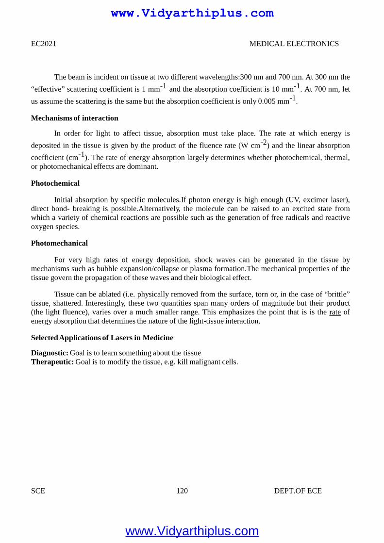
EC2021 MEDICAL ELECTRONICS
SCE 120 DEPT.OF ECE
The beam is incident on tissue at two different wavelengths:300 nm and 700 nm. At 300 nm the
“effective” scattering coefficient is 1 mm-1 and the absorption coefficient is 10 mm-1. At 700 nm, let
us assume the scattering is the same but the absorption coefficient is only 0.005 mm-1.
Mechanisms of interaction
In order for light to affect tissue, absorption must take place. The rate at which energy is
deposited in the tissue is given by the product of the fluence rate (W cm-2) and the linear absorption
coefficient (cm-1). The rate of energy absorption largely determines whether photochemical, thermal,or photomechanical effects are dominant.
Photochemical
Initial absorption by specific molecules.If photon energy is high enough (UV, excimer laser),direct bond- breaking is possible.Alternatively, the molecule can be raised to an excited state fromwhich a variety of chemical reactions are possible such as the generation of free radicals and reactiveoxygen species.
Photomechanical
For very high rates of energy deposition, shock waves can be generated in the tissue bymechanisms such as bubble expansion/collapse or plasma formation.The mechanical properties of thetissue govern the propagation of these waves and their biological effect.
Tissue can be ablated (i.e. physically removed from the surface, torn or, in the case of “brittle”tissue, shattered. Interestingly, these two quantities span many orders of magnitude but their product(the light fluence), varies over a much smaller range. This emphasizes the point that is is the rate ofenergy absorption that determines the nature of the light-tissue interaction.
SelectedApplications of Lasers in Medicine
Diagnostic: Goal is to learn something about the tissueTherapeutic: Goal is to modify the tissue, e.g. kill malignant cells.
www.Vidyarthiplus.com
www.Vidyarthiplus.com
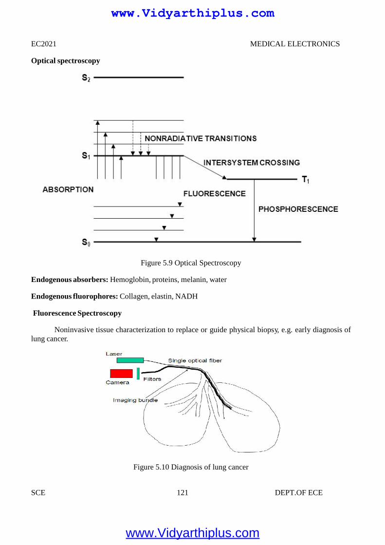
EC2021 MEDICAL ELECTRONICS
SCE 121 DEPT.OF ECE
Optical spectroscopy
Figure 5.9 Optical Spectroscopy
Endogenous absorbers: Hemoglobin, proteins, melanin, water
Endogenous fluorophores: Collagen, elastin, NADH
Fluorescence Spectroscopy
Noninvasive tissue characterization to replace or guide physical biopsy, e.g. early diagnosis oflung cancer.
Figure 5.10 Diagnosis of lung cancer
www.Vidyarthiplus.com
www.Vidyarthiplus.com
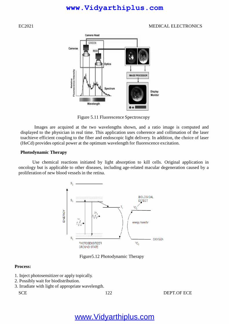
EC2021 MEDICAL ELECTRONICS
SCE 122 DEPT.OF ECE
Figure 5.11 Fluorescence Spectroscopy
Images are acquired at the two wavelengths shown, and a ratio image is computed anddisplayed to the physician in real time. This application uses coherence and collimation of the lasertoachieve efficient coupling to the fiber and endoscopic light delivery. In addition, the choice of laser(HeCd) provides optical power at the optimum wavelength for fluorescence excitation.
Photodynamic Therapy
Use chemical reactions initiated by light absorption to kill cells. Original application inoncology but is applicable to other diseases, including age-related macular degeneration caused by aproliferation of new blood vessels in the retina.
Figure5.12 Photodynamic Therapy
Process:
1. Inject photosensitizer or apply topically.2. Possibly wait for biodistribution.3. Irradiate with light of appropriate wavelength.
www.Vidyarthiplus.com
www.Vidyarthiplus.com
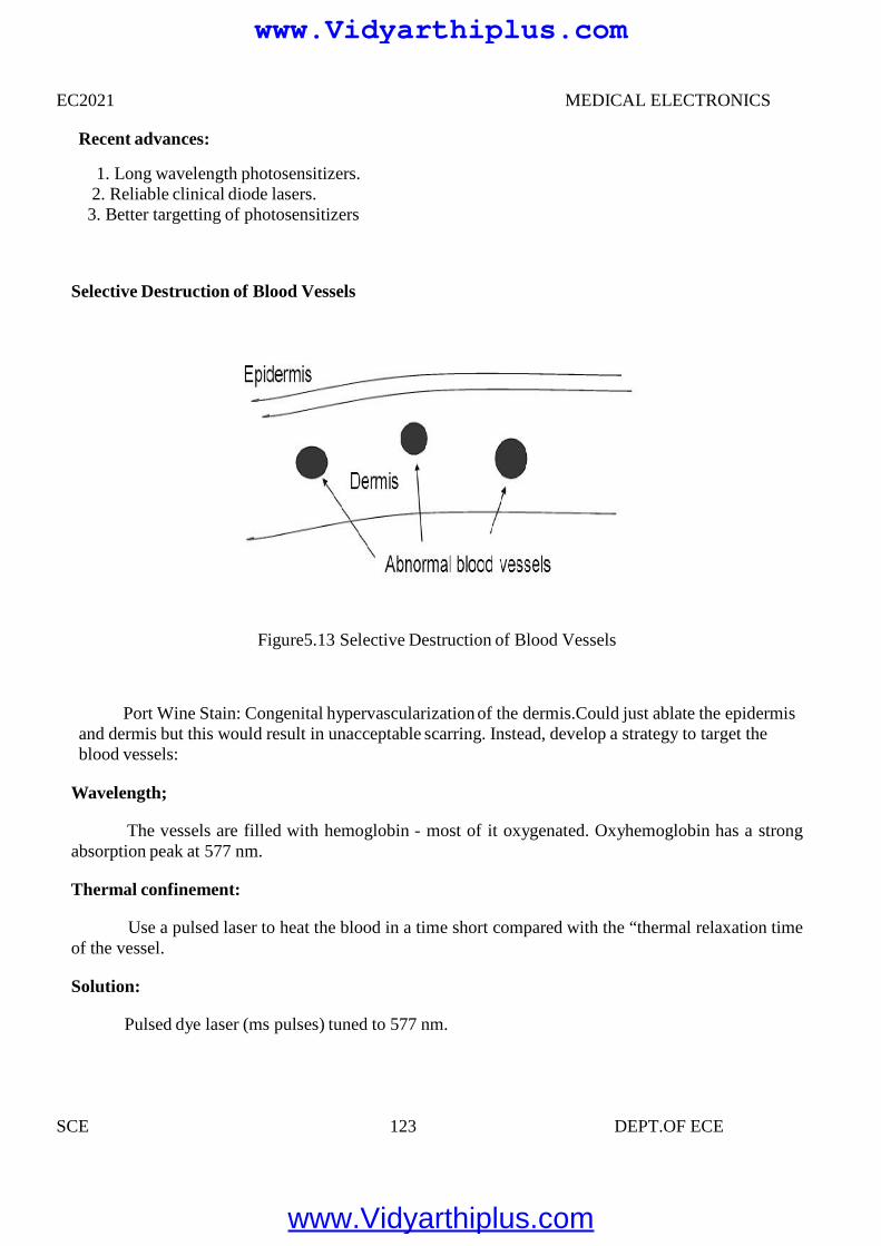
EC2021 MEDICAL ELECTRONICS
SCE 123 DEPT.OF ECE
Recent advances:
1. Long wavelength photosensitizers.2. Reliable clinical diode lasers.3. Better targetting of photosensitizers
Selective Destruction of Blood Vessels
Figure5.13 Selective Destruction of Blood Vessels
Port Wine Stain: Congenital hypervascularization of the dermis.Could just ablate the epidermisand dermis but this would result in unacceptable scarring. Instead, develop a strategy to target theblood vessels:
Wavelength;
The vessels are filled with hemoglobin - most of it oxygenated. Oxyhemoglobin has a strongabsorption peak at 577 nm.
Thermal confinement:
Use a pulsed laser to heat the blood in a time short compared with the “thermal relaxation timeof the vessel.
Solution:
Pulsed dye laser (ms pulses) tuned to 577 nm.
www.Vidyarthiplus.com
www.Vidyarthiplus.com
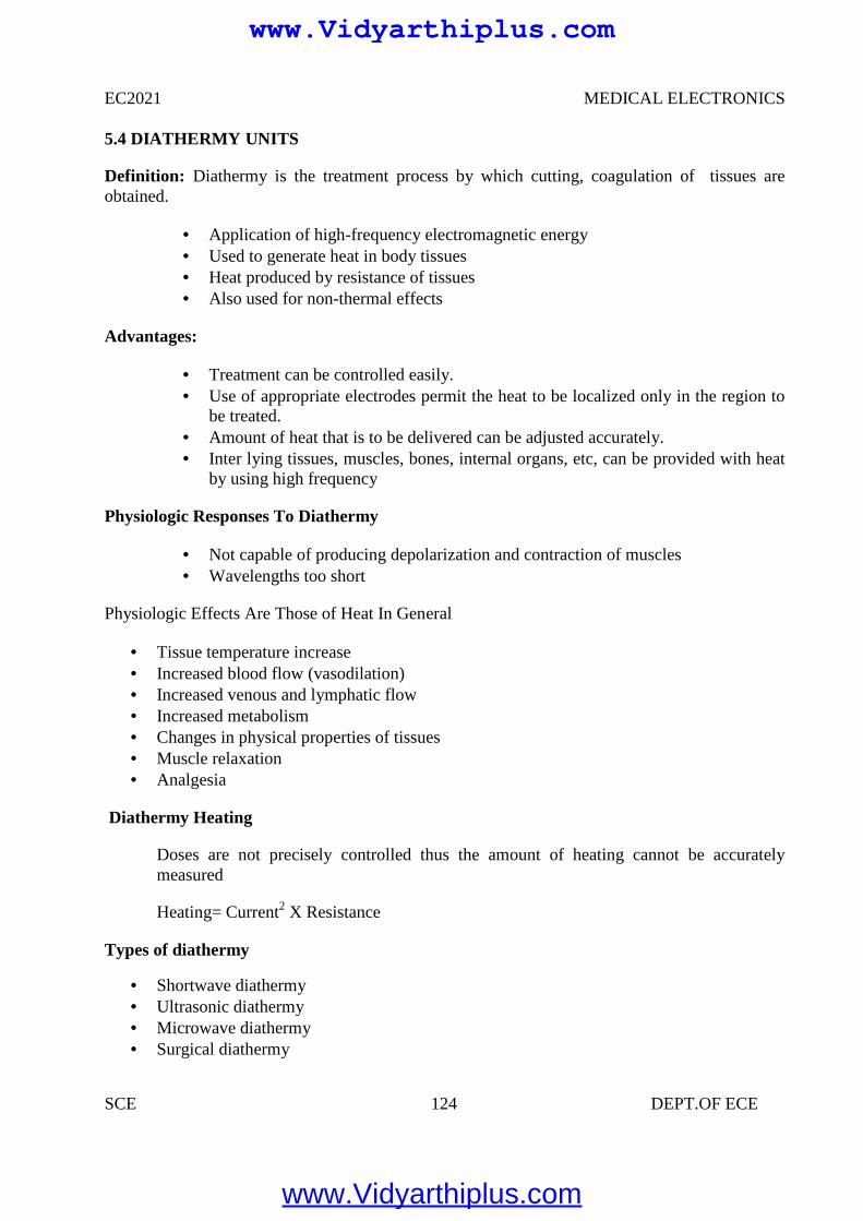
EC2021 MEDICAL ELECTRONICS
SCE 124 DEPT.OF ECE
5.4 DIATHERMY UNITS
Definition: Diathermy is the treatment process by which cutting, coagulation of tissues areobtained.
Application of high-frequency electromagnetic energy Used to generate heat in body tissues Heat produced by resistance of tissues Also used for non-thermal effects
Advantages:
Treatment can be controlled easily. Use of appropriate electrodes permit the heat to be localized only in the region to
be treated. Amount of heat that is to be delivered can be adjusted accurately. Inter lying tissues, muscles, bones, internal organs, etc, can be provided with heat
by using high frequency
Physiologic Responses To Diathermy
Not capable of producing depolarization and contraction of muscles Wavelengths too short
Physiologic Effects Are Those of Heat In General
Tissue temperature increase Increased blood flow (vasodilation) Increased venous and lymphatic flow Increased metabolism Changes in physical properties of tissues Muscle relaxation Analgesia
Diathermy Heating
Doses are not precisely controlled thus the amount of heating cannot be accuratelymeasured
Heating= Current2 X Resistance
Types of diathermy
Shortwave diathermy Ultrasonic diathermy Microwave diathermy Surgical diathermy
www.Vidyarthiplus.com
www.Vidyarthiplus.com
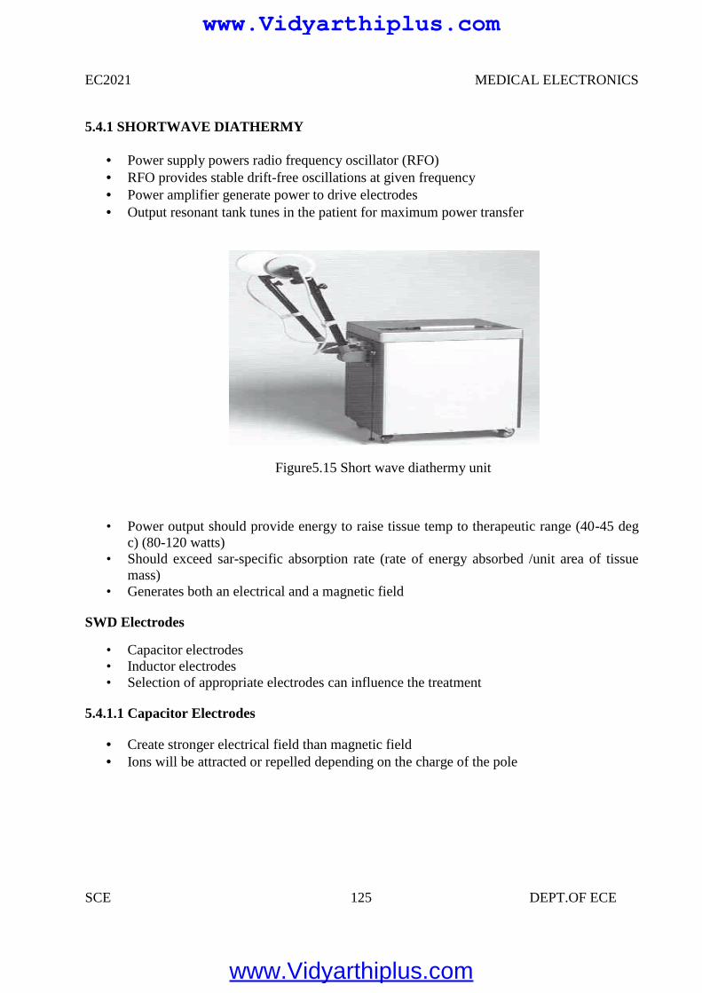
EC2021 MEDICAL ELECTRONICS
SCE 125 DEPT.OF ECE
5.4.1 SHORTWAVE DIATHERMY
Power supply powers radio frequency oscillator (RFO) RFO provides stable drift-free oscillations at given frequency Power amplifier generate power to drive electrodes Output resonant tank tunes in the patient for maximum power transfer
Figure5.15 Short wave diathermy unit
• Power output should provide energy to raise tissue temp to therapeutic range (40-45 degc) (80-120 watts)
• Should exceed sar-specific absorption rate (rate of energy absorbed /unit area of tissuemass)
• Generates both an electrical and a magnetic field
SWD Electrodes
• Capacitor electrodes• Inductor electrodes• Selection of appropriate electrodes can influence the treatment
5.4.1.1 Capacitor Electrodes
Create stronger electrical field than magnetic field Ions will be attracted or repelled depending on the charge of the pole
www.Vidyarthiplus.com
www.Vidyarthiplus.com
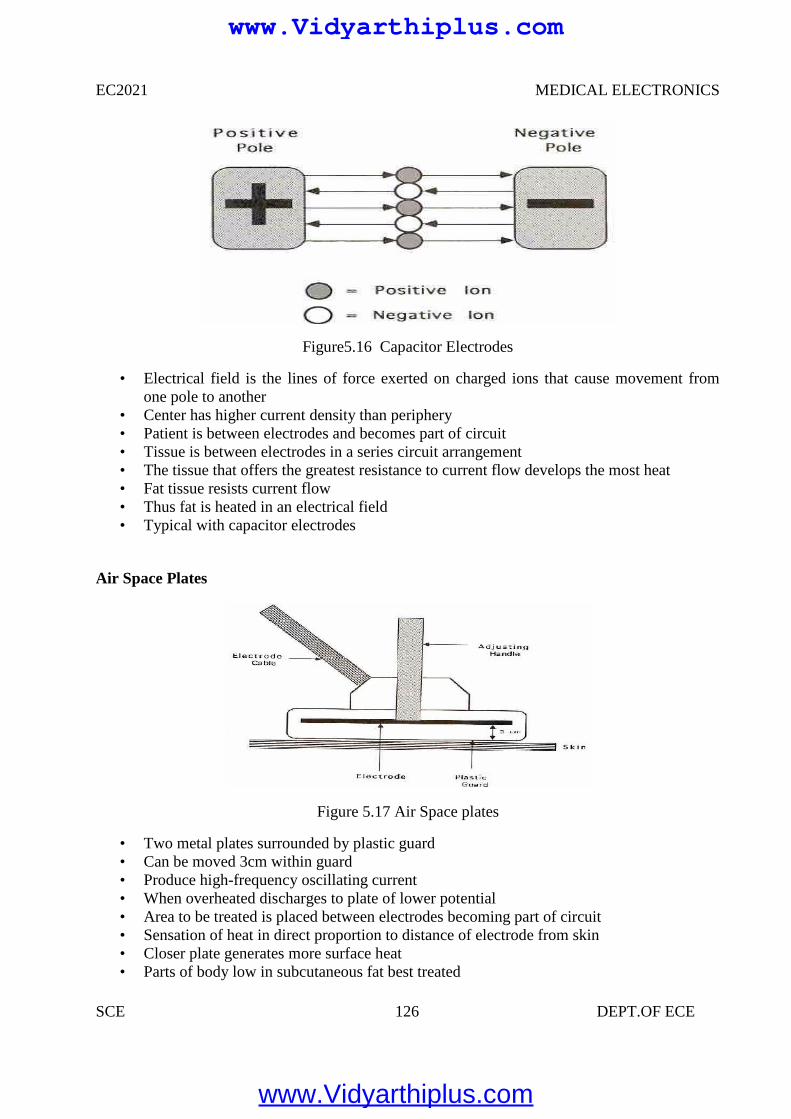
EC2021 MEDICAL ELECTRONICS
SCE 126 DEPT.OF ECE
Figure5.16 Capacitor Electrodes
• Electrical field is the lines of force exerted on charged ions that cause movement fromone pole to another
• Center has higher current density than periphery• Patient is between electrodes and becomes part of circuit• Tissue is between electrodes in a series circuit arrangement• The tissue that offers the greatest resistance to current flow develops the most heat• Fat tissue resists current flow• Thus fat is heated in an electrical field• Typical with capacitor electrodes
Air Space Plates
Figure 5.17 Air Space plates
• Two metal plates surrounded by plastic guard• Can be moved 3cm within guard• Produce high-frequency oscillating current• When overheated discharges to plate of lower potential• Area to be treated is placed between electrodes becoming part of circuit• Sensation of heat in direct proportion to distance of electrode from skin• Closer plate generates more surface heat• Parts of body low in subcutaneous fat best treated
www.Vidyarthiplus.com
www.Vidyarthiplus.com
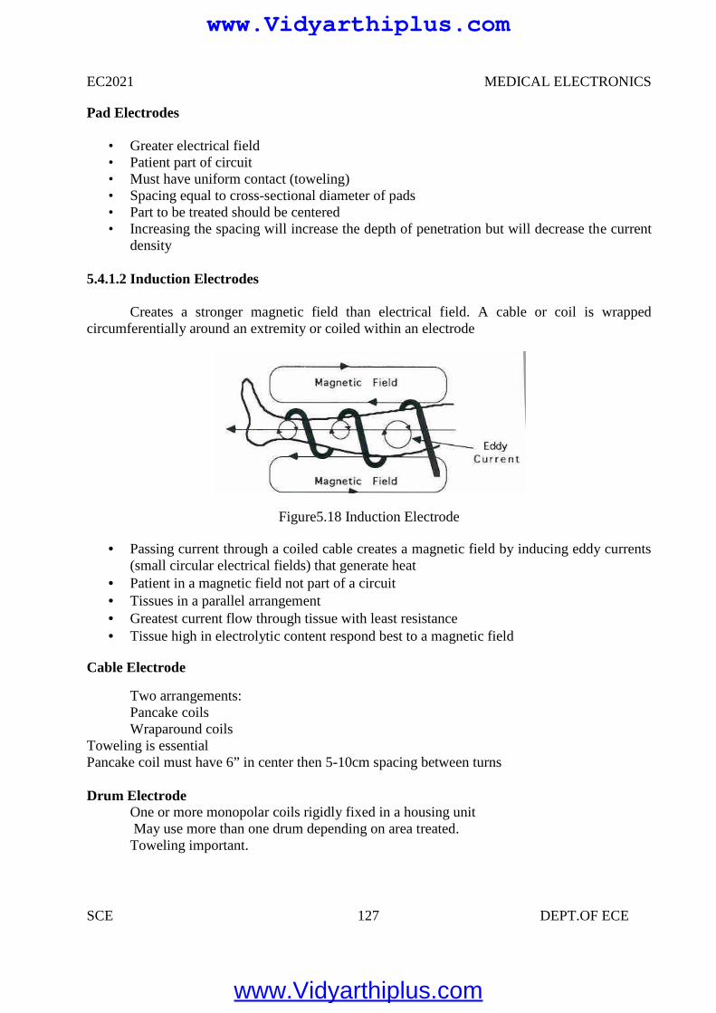
EC2021 MEDICAL ELECTRONICS
SCE 127 DEPT.OF ECE
Pad Electrodes
• Greater electrical field• Patient part of circuit• Must have uniform contact (toweling)• Spacing equal to cross-sectional diameter of pads• Part to be treated should be centered• Increasing the spacing will increase the depth of penetration but will decrease the current
density
5.4.1.2 Induction Electrodes
Creates a stronger magnetic field than electrical field. A cable or coil is wrappedcircumferentially around an extremity or coiled within an electrode
Figure5.18 Induction Electrode
Passing current through a coiled cable creates a magnetic field by inducing eddy currents(small circular electrical fields) that generate heat
Patient in a magnetic field not part of a circuit Tissues in a parallel arrangement Greatest current flow through tissue with least resistance Tissue high in electrolytic content respond best to a magnetic field
Cable Electrode
Two arrangements:Pancake coilsWraparound coils
Toweling is essentialPancake coil must have 6” in center then 5-10cm spacing between turns
Drum ElectrodeOne or more monopolar coils rigidly fixed in a housing unitMay use more than one drum depending on area treated.Toweling important.
www.Vidyarthiplus.com
www.Vidyarthiplus.com
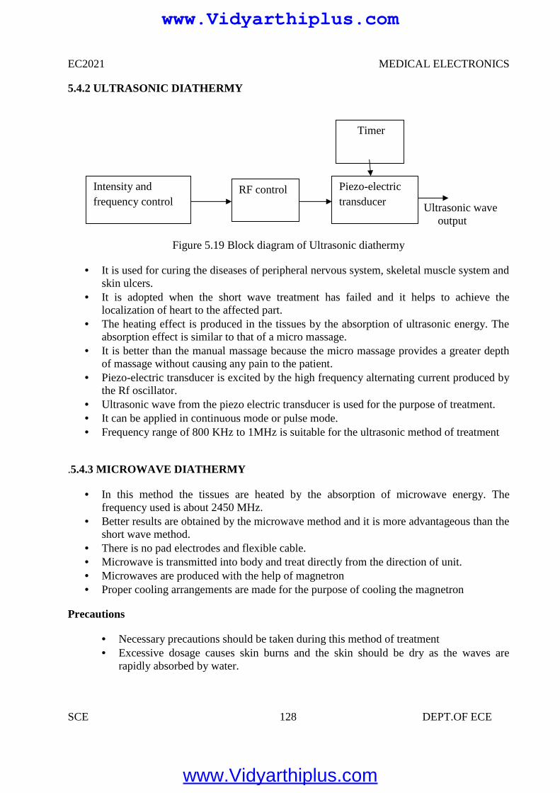
EC2021 MEDICAL ELECTRONICS
SCE 128 DEPT.OF ECE
5.4.2 ULTRASONIC DIATHERMY
Ultrasonic waveoutput
Figure 5.19 Block diagram of Ultrasonic diathermy
It is used for curing the diseases of peripheral nervous system, skeletal muscle system andskin ulcers.
It is adopted when the short wave treatment has failed and it helps to achieve thelocalization of heart to the affected part.
The heating effect is produced in the tissues by the absorption of ultrasonic energy. Theabsorption effect is similar to that of a micro massage.
It is better than the manual massage because the micro massage provides a greater depthof massage without causing any pain to the patient.
Piezo-electric transducer is excited by the high frequency alternating current produced bythe Rf oscillator.
Ultrasonic wave from the piezo electric transducer is used for the purpose of treatment. It can be applied in continuous mode or pulse mode. Frequency range of 800 KHz to 1MHz is suitable for the ultrasonic method of treatment
.5.4.3 MICROWAVE DIATHERMY
In this method the tissues are heated by the absorption of microwave energy. Thefrequency used is about 2450 MHz.
Better results are obtained by the microwave method and it is more advantageous than theshort wave method.
There is no pad electrodes and flexible cable. Microwave is transmitted into body and treat directly from the direction of unit. Microwaves are produced with the help of magnetron Proper cooling arrangements are made for the purpose of cooling the magnetron
Precautions
Necessary precautions should be taken during this method of treatment Excessive dosage causes skin burns and the skin should be dry as the waves are
rapidly absorbed by water.
Intensity andfrequency control
RF control Piezo-electrictransducer
Timer
www.Vidyarthiplus.com
www.Vidyarthiplus.com
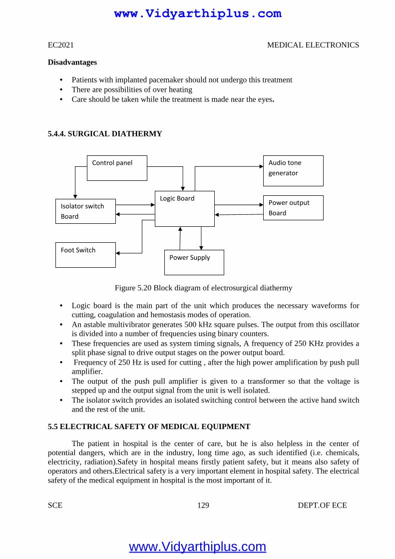
EC2021 MEDICAL ELECTRONICS
SCE 129 DEPT.OF ECE
Disadvantages
Patients with implanted pacemaker should not undergo this treatment There are possibilities of over heating Care should be taken while the treatment is made near the eyes.
5.4.4. SURGICAL DIATHERMY
Figure 5.20 Block diagram of electrosurgical diathermy
Logic board is the main part of the unit which produces the necessary waveforms forcutting, coagulation and hemostasis modes of operation.
An astable multivibrator generates 500 kHz square pulses. The output from this oscillatoris divided into a number of frequencies using binary counters.
These frequencies are used as system timing signals, A frequency of 250 KHz provides asplit phase signal to drive output stages on the power output board.
Frequency of 250 Hz is used for cutting , after the high power amplification by push pullamplifier.
The output of the push pull amplifier is given to a transformer so that the voltage isstepped up and the output signal from the unit is well isolated.
The isolator switch provides an isolated switching control between the active hand switchand the rest of the unit.
5.5 ELECTRICAL SAFETY OF MEDICAL EQUIPMENT
The patient in hospital is the center of care, but he is also helpless in the center ofpotential dangers, which are in the industry, long time ago, as such identified (i.e. chemicals,electricity, radiation).Safety in hospital means firstly patient safety, but it means also safety ofoperators and others.Electrical safety is a very important element in hospital safety. The electricalsafety of the medical equipment in hospital is the most important of it.
Isolator switchBoard
Foot SwitchPower Supply
Logic Board Power outputBoard
Audio tonegenerator
Control panel
www.Vidyarthiplus.com
www.Vidyarthiplus.com
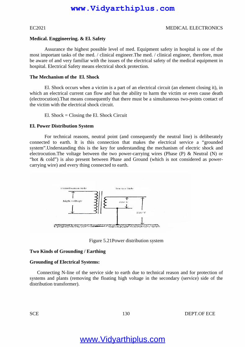
EC2021 MEDICAL ELECTRONICS
SCE 130 DEPT.OF ECE
Medical. Enggineering. & El. Safety
Assurance the highest possible level of med. Equipment safety in hospital is one of themost important tasks of the med. / clinical engineer.The med. / clinical engineer, therefore, mustbe aware of and very familiar with the issues of the electrical safety of the medical equipment inhospital. Electrical Safety means electrical shock protection.
The Mechanism of the El. Shock
El. Shock occurs when a victim is a part of an electrical circuit (an element closing it), inwhich an electrical current can flow and has the ability to harm the victim or even cause death(electrocution).That means consequently that there must be a simultaneous two-points contact ofthe victim with the electrical shock circuit.
El. Shock = Closing the El. Shock Circuit
El. Power Distribution System
For technical reasons, neutral point (and consequently the neutral line) is deliberatelyconnected to earth. It is this connection that makes the electrical service a “groundedsystem”.Understanding this is the key for understanding the mechanism of electric shock andelectrocution.The voltage between the two power-carrying wires (Phase (P) & Neutral (N) or“hot & cold”) is also present between Phase and Ground (which is not considered as power-carrying wire) and every thing connected to earth.
Figure 5.21Power distribution system
Two Kinds of Grounding / Earthing
Grounding of Electrical Systems:
Connecting N-line of the service side to earth due to technical reason and for protection ofsystems and plants (removing the floating high voltage in the secondary (service) side of thedistribution transformer).
www.Vidyarthiplus.com
www.Vidyarthiplus.com
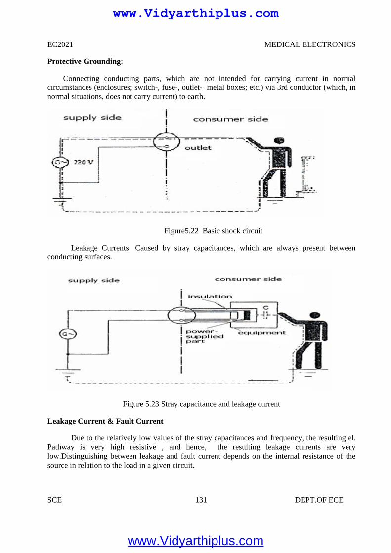
EC2021 MEDICAL ELECTRONICS
SCE 131 DEPT.OF ECE
Protective Grounding:
Connecting conducting parts, which are not intended for carrying current in normalcircumstances (enclosures; switch-, fuse-, outlet- metal boxes; etc.) via 3rd conductor (which, innormal situations, does not carry current) to earth.
Figure5.22 Basic shock circuit
Leakage Currents: Caused by stray capacitances, which are always present betweenconducting surfaces.
Figure 5.23 Stray capacitance and leakage current
Leakage Current & Fault Current
Due to the relatively low values of the stray capacitances and frequency, the resulting el.Pathway is very high resistive , and hence, the resulting leakage currents are verylow.Distinguishing between leakage and fault current depends on the internal resistance of thesource in relation to the load in a given circuit.
www.Vidyarthiplus.com
www.Vidyarthiplus.com
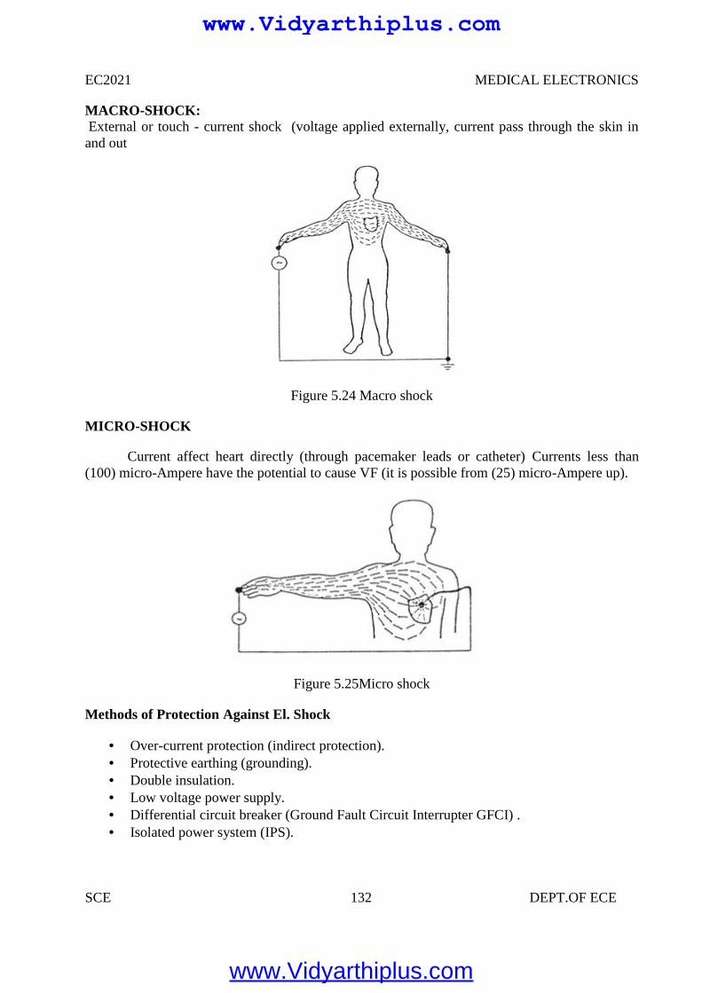
EC2021 MEDICAL ELECTRONICS
SCE 132 DEPT.OF ECE
MACRO-SHOCK:External or touch - current shock (voltage applied externally, current pass through the skin inand out
Figure 5.24 Macro shock
MICRO-SHOCK
Current affect heart directly (through pacemaker leads or catheter) Currents less than(100) micro-Ampere have the potential to cause VF (it is possible from (25) micro-Ampere up).
Figure 5.25Micro shock
Methods of Protection Against El. Shock
Over-current protection (indirect protection). Protective earthing (grounding). Double insulation. Low voltage power supply. Differential circuit breaker (Ground Fault Circuit Interrupter GFCI) . Isolated power system (IPS).
www.Vidyarthiplus.com
www.Vidyarthiplus.com
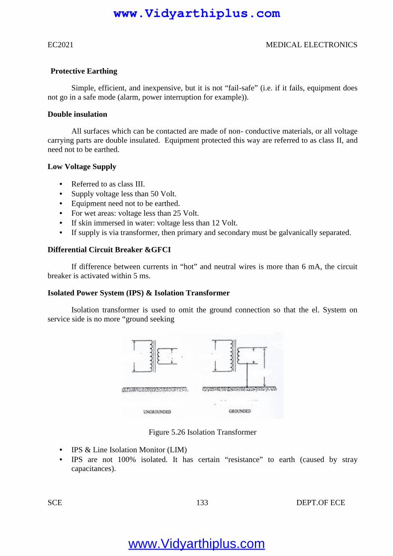
EC2021 MEDICAL ELECTRONICS
SCE 133 DEPT.OF ECE
Protective Earthing
Simple, efficient, and inexpensive, but it is not “fail-safe” (i.e. if it fails, equipment doesnot go in a safe mode (alarm, power interruption for example)).
Double insulation
All surfaces which can be contacted are made of non- conductive materials, or all voltagecarrying parts are double insulated. Equipment protected this way are referred to as class II, andneed not to be earthed.
Low Voltage Supply
Referred to as class III. Supply voltage less than 50 Volt. Equipment need not to be earthed. For wet areas: voltage less than 25 Volt. If skin immersed in water: voltage less than 12 Volt. If supply is via transformer, then primary and secondary must be galvanically separated.
Differential Circuit Breaker &GFCI
If difference between currents in “hot” and neutral wires is more than 6 mA, the circuitbreaker is activated within 5 ms.
Isolated Power System (IPS) & Isolation Transformer
Isolation transformer is used to omit the ground connection so that the el. System onservice side is no more “ground seeking
Figure 5.26 Isolation Transformer
IPS & Line Isolation Monitor (LIM) IPS are not 100% isolated. It has certain “resistance” to earth (caused by stray
capacitances).
www.Vidyarthiplus.com
www.Vidyarthiplus.com
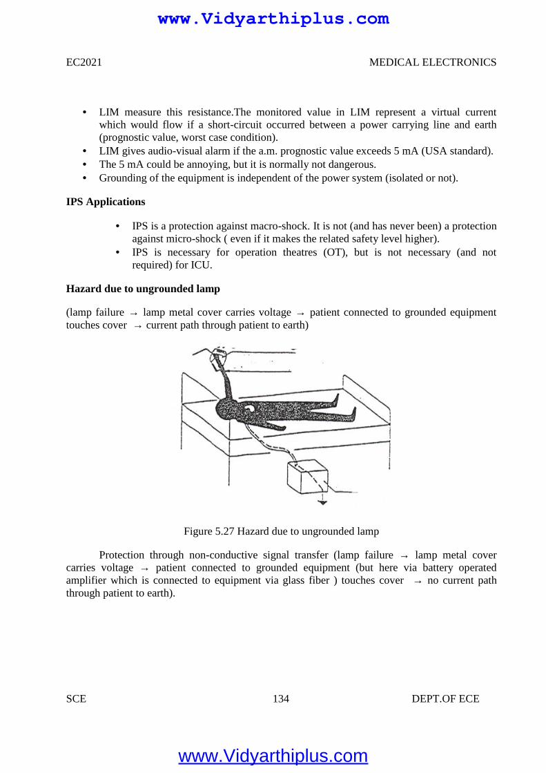
EC2021 MEDICAL ELECTRONICS
SCE 134 DEPT.OF ECE
LIM measure this resistance.The monitored value in LIM represent a virtual currentwhich would flow if a short-circuit occurred between a power carrying line and earth(prognostic value, worst case condition).
LIM gives audio-visual alarm if the a.m. prognostic value exceeds 5 mA (USA standard). The 5 mA could be annoying, but it is normally not dangerous. Grounding of the equipment is independent of the power system (isolated or not).
IPS Applications
IPS is a protection against macro-shock. It is not (and has never been) a protectionagainst micro-shock ( even if it makes the related safety level higher).
IPS is necessary for operation theatres (OT), but is not necessary (and notrequired) for ICU.
Hazard due to ungrounded lamp
(lamp failure → lamp metal cover carries voltage → patient connected to grounded equipmenttouches cover → current path through patient to earth)
Figure 5.27 Hazard due to ungrounded lamp
Protection through non-conductive signal transfer (lamp failure → lamp metal covercarries voltage → patient connected to grounded equipment (but here via battery operatedamplifier which is connected to equipment via glass fiber ) touches cover → no current paththrough patient to earth).
www.Vidyarthiplus.com
www.Vidyarthiplus.com
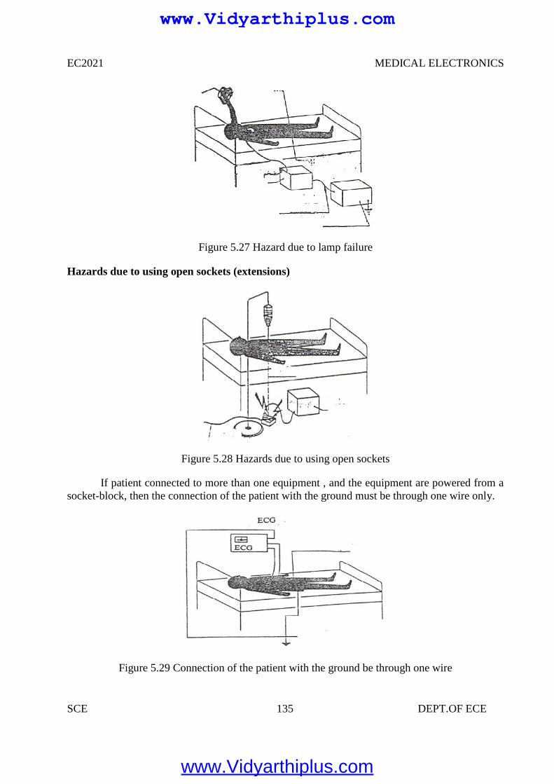
EC2021 MEDICAL ELECTRONICS
SCE 135 DEPT.OF ECE
Figure 5.27 Hazard due to lamp failure
Hazards due to using open sockets (extensions)
Figure 5.28 Hazards due to using open sockets
If patient connected to more than one equipment , and the equipment are powered from asocket-block, then the connection of the patient with the ground must be through one wire only.
Figure 5.29 Connection of the patient with the ground be through one wire
www.Vidyarthiplus.com
www.Vidyarthiplus.com
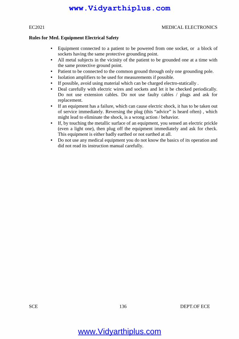
EC2021 MEDICAL ELECTRONICS
SCE 136 DEPT.OF ECE
Rules for Med. Equipment Electrical Safety
Equipment connected to a patient to be powered from one socket, or a block ofsockets having the same protective grounding point.
All metal subjects in the vicinity of the patient to be grounded one at a time withthe same protective ground point.
Patient to be connected to the common ground through only one grounding pole. Isolation amplifiers to be used for measurements if possible. If possible, avoid using material which can be charged electro-statically . Deal carefully with electric wires and sockets and let it be checked periodically.
Do not use extension cables. Do not use faulty cables / plugs and ask forreplacement.
If an equipment has a failure, which can cause electric shock, it has to be taken outof service immediately. Reversing the plug (this “advice” is heard often) , whichmight lead to eliminate the shock, is a wrong action / behavior.
If, by touching the metallic surface of an equipment, you sensed an electric prickle(even a light one), then plug off the equipment immediately and ask for check.This equipment is either badly earthed or not earthed at all.
Do not use any medical equipment you do not know the basics of its operation anddid not read its instruction manual carefully.
www.Vidyarthiplus.com
www.Vidyarthiplus.com
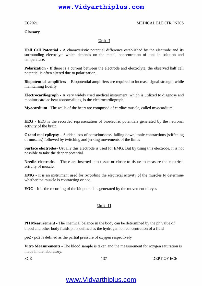
EC2021 MEDICAL ELECTRONICS
SCE 137 DEPT.OF ECE
Glossary
Unit -I
Half Cell Potential - A characteristic potential difference established by the electrode and itssurrounding electrolyte which depends on the metal, concentration of ions in solution andtemperature.
Polarization - If there is a current between the electrode and electrolyte, the observed half cellpotential is often altered due to polarization.
Biopotential amplifiers - Biopotential amplifiers are required to increase signal strength whilemaintaining fidelity
Electrocardiograph - A very widely used medical instrument, which is utilized to diagnose andmonitor cardiac beat abnormalities, is the electrocardiograph
Myocardium - The walls of the heart are composed of cardiac muscle, called myocardium.
EEG - EEG is the recorded representation of bioelectric potentials generated by the neuronalactivity of the brain.
Grand mal epilepsy – Sudden loss of consciousness, falling down, tonic contractions (stiffeningof muscles) followed by twitching and jerking movements of the limbs
Surface electrodes- Usually this electrode is used for EMG. But by using this electrode, it is notpossible to take the deeper potential.
Needle electrodes – These are inserted into tissue or closer to tissue to measure the electricalactivity of muscle.
EMG - It is an instrument used for recording the electrical activity of the muscles to determinewhether the muscle is contracting or not.
EOG - It is the recording of the biopotentials generated by the movement of eyes
Unit –II
PH Measurement - The chemical balance in the body can be determined by the ph value ofblood and other body fluids.ph is defined as the hydrogen ion concentration of a fluid
po2 - po2 is defined as the partial pressure of oxygen respectively
Vitro Measurements - The blood sample is taken and the measurement for oxygen saturation ismade in the laboratory.
www.Vidyarthiplus.com
www.Vidyarthiplus.com
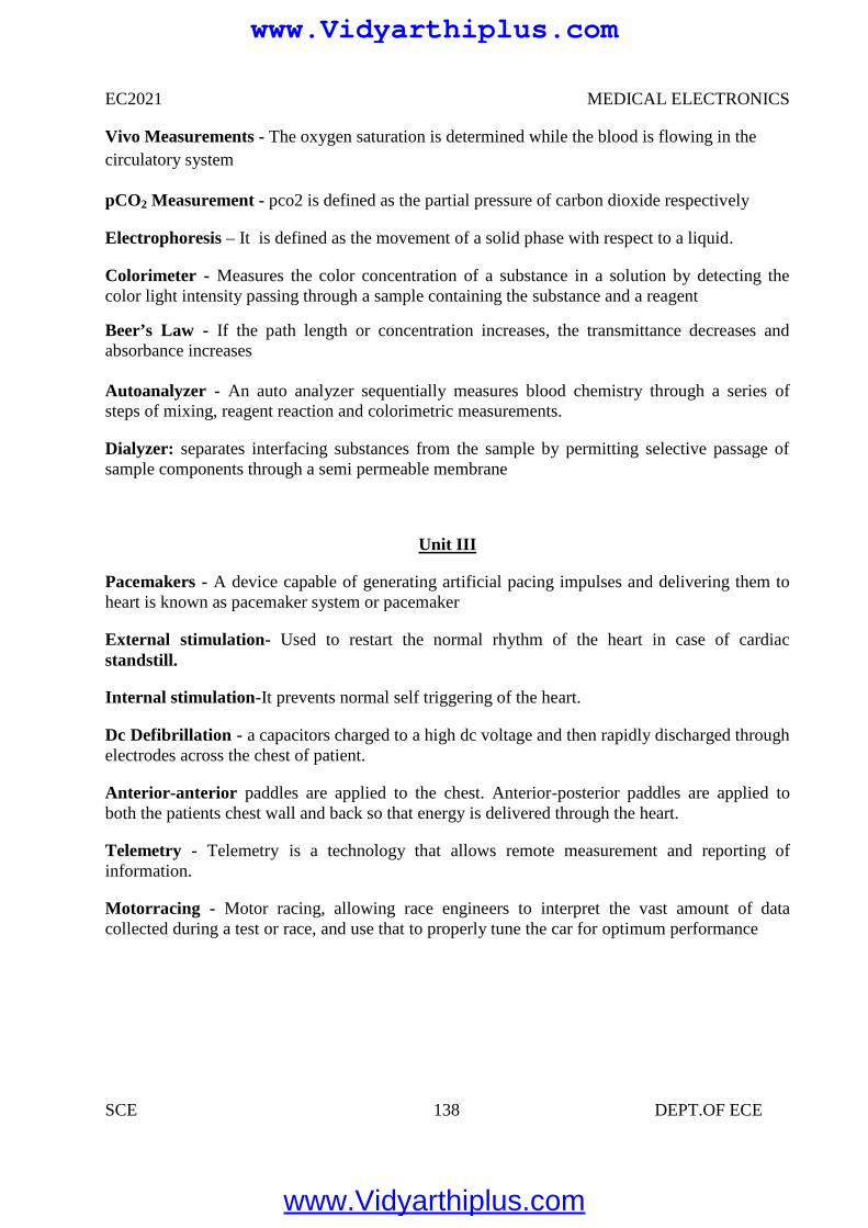
EC2021 MEDICAL ELECTRONICS
SCE 138 DEPT.OF ECE
Vivo Measurements - The oxygen saturation is determined while the blood is flowing in thecirculatory system
pCO2 Measurement - pco2 is defined as the partial pressure of carbon dioxide respectively
Electrophoresis – It is defined as the movement of a solid phase with respect to a liquid.
Colorimeter - Measures the color concentration of a substance in a solution by detecting thecolor light intensity passing through a sample containing the substance and a reagent
Beer’s Law - If the path length or concentration increases, the transmittance decreases andabsorbance increases
Autoanalyzer - An auto analyzer sequentially measures blood chemistry through a series ofsteps of mixing, reagent reaction and colorimetric measurements.
Dialyzer: separates interfacing substances from the sample by permitting selective passage ofsample components through a semi permeable membrane
Unit III
Pacemakers - A device capable of generating artificial pacing impulses and delivering them toheart is known as pacemaker system or pacemaker
External stimulation- Used to restart the normal rhythm of the heart in case of cardiacstandstill.
Internal stimulation-It prevents normal self triggering of the heart.
Dc Defibrillation - a capacitors charged to a high dc voltage and then rapidly discharged throughelectrodes across the chest of patient.
Anterior-anterior paddles are applied to the chest. Anterior-posterior paddles are applied toboth the patients chest wall and back so that energy is delivered through the heart.
Telemetry - Telemetry is a technology that allows remote measurement and reporting ofinformation.
Motorracing - Motor racing, allowing race engineers to interpret the vast amount of datacollected during a test or race, and use that to properly tune the car for optimum performance
www.Vidyarthiplus.com
www.Vidyarthiplus.com
EC2021 MEDICAL ELECTRONICS
SCE 139 DEPT.OF ECE
Unit IV
Ionizing Radiation - ionizing radiation is harmful and potentially lethal to living beings but canhave health benefits in radiation therapy for the treatment of cancer and thyrotoxicosis.
Deterministic effects- (harmful tissue reactions) due in large part to the killing/ malfunction ofcells following high doses
Stochastic effects, i.e., cancer and heritable effects involving either cancer development inexposed individuals owing to mutation of somatic cells or heritable disease in their offspringowing to mutation of reproductive (germ) cells.
Alpha particles - Alpha particles consist of two protons and two neutrons bound together into aparticle identical to a helium nucleus
Beta particles - Beta particles are high-energy, high-speed electrons or positrons emitted bycertain types of radioactive nuclei, such as potassium-40
Positron - The positron or ant electron is the antiparticle or the antimatter counterpart of theelectron.
Cancer - Cancers are growths of cells (cancerous tumours) which are out of control. As a resultof this, they do not perform their intended function
Static Imaging - There is a time delay between injecting the tracer and the build-up of radiationin the organ. Static studies are performed on the brain, bone or lungs scans
Collimator - It is placed between the patient and aluminium filter. It is nothing but an aperture
Unit V
Thermograph - Thermograph, thermal imaging, or thermal video, is a type of infrared imaging
Infrared thermography - is the science of acquisition and analysis of thermal information byusing non contact thermal imaging devices
Liquid Crystal Thermography - Liquid crystals are a class of compounds which exhibitcolour temperature sensitivity in the cholestric phase
Endoscopy - An endoscopy is a test that looks inside the body. The endoscope is a longflexible tube that can be swallowed. It has a camera and light inside it. Some doctors call it atelescope
www.Vidyarthiplus.com
www.Vidyarthiplus.com
EC2021 MEDICAL ELECTRONICS
SCE 140 DEPT.OF ECE
Upper Endoscopy - Upper endoscopy enables the physician to look inside the esophagus,stomach, and duodenum (first part of the small intestine)
Arthroscopy: Examination of joints for diagnosis and treatment (arthroscopic surgery)
Bronchoscopy: Examination of the trachea and lung's bronchial trees to reveal abscesses,bronchitis, carcinoma, tumors, tuberculosis, alveolitis, infection, inflammation
Colonoscopy: Examination of the inside of the colon and large intestine to detect polyps, tumors,ulceration, inflammation, colitis diverticula, Chrohn's disease, and discovery and removal offoreign bodies.
Colposcopy: Direct visualization of the vagina and cervix to detect cancer, inflammation, andother conditions.
Cystoscopy: Examination of the bladder, urethra, urinary tract, uteral orifices, and prostate (men)with insertion of the endoscope through the urethra
EGD (Esophogealgastroduodensoscopy): visual examination of the upper gastro-intestinal (GI)tract. (also referred to as gastroscopy) to reveal hemorrhage, hiatal hernia, inflammation of theesophagus, gastric ulcers.
Laparoscopy: visualization of the stomach, liver and other abdominal organs including thefemale reproductive organs, for example, the fallopian tubes.
Laryngoscopy: examination of the larynx (voice box).
Diagnostic: Goal is to learn something about the tissue
Therapeutic: Goal is to modify the tissue, e.g. kill malignant cells.
Diathermy - is the treatment process by which cutting, coagulation of tissues are obtained.
Induction Electrodes- Creates a stronger magnetic field than electrical field. A cable or coil iswrapped circumferentially around an extremity or coiled within an electrode
www.Vidyarthiplus.com
www.Vidyarthiplus.com
EC2021 MEDICAL ELECTRONICS
SCE 141 DEPT.OF ECE
UNIT I
ELECTRO PHYSIOLOGY AND BIO POTENTIAL RECORDING
PART-A
1. What is meant by cell?
The basic living unit of the body is cell. The function of organs and other Structureof the body is understood by cell organization.
2. Give the abbreviation form for RNA, DNA?
RNA –Ribo Nucleic Acid DNA—De- Oxy Nucleic Acid
3. What are resting and action potential, bio electric potential?
The membrane potential caused by the different concentration of ions is calledrestingpotential. It is caused by very rapid change of membrane Permeability to sodium ionsfollowed by recovery period.The positive potential of the cell membrane during excitation iscalled action potential. Certain systems of the body generate their own monitoringsignals conveying useful information about the functions they represent. Such signalsare bio electric potentials and are related to nerve conduction, brain activity, heart beat etc.
4.What is meant by measurement.
Measurement is an act or the result of comparison between the quantity and a predefinedstandard.
5. Mention the basic requirements of measurement.
The standard used for comparison purpose must be accurately defined and shouldbe commonly accepted. The apparatus used and the method adopted must be provable.
6. What are the 2 methods for measurement?
1.Directmethod2. Indirect method.
7. Explain the function of measurement system.
The measurement system consists of a transuding element which converts the quantity to bemeasured in an analogous form the analogous signal is then processed by some intermediate meansand is then fed to the end device which presents the results of the measurement.
8. Define Instrument.
Instrument is defined as a device for determining the value or magnitude of a quantity or variable.
www.Vidyarthiplus.com
www.Vidyarthiplus.com
EC2021 MEDICAL ELECTRONICS
SCE 142 DEPT.OF ECE
9. List the types of instruments?
The 3 types of instruments are
1) Mechanical Instruments2) Electrical Instruments and3) Electronic Instruments.
10. Classify instruments.
1)AbsoluteInstruments
2)Secondary Instruments
11.What is meant by Resting Potential?
Equilibrium is reached with a potential difference across the membrane such that negative oninside and positive on outside. This membrane potential caused by the different concentrationof irons is called Resting Potential.
12.What is meant by Action Potential?
Cell has a slightly positive potential on the inside due to imbalance of potassium ions. Thispositive potential of the cell membrane during excitation is called Action Potential and is about 20 mV.
13.Give any 4 factors to be considered when we design any medical Instrument?
Accuracy,Frequency Response,Linearity, S/N ratio,Stability,sensitivity
14.What is Electrode Potential?
The voltage developed at an electrode-electrolyte interface is known as Electrode Potential.
15.What is the purpose of electrode paste?
The electrode paste decreases the impedance of the contact the artifacts resulting from themovement of the electrode or patient.16.Give the different types of electrodes?
Microelectrodes,Depth and needle electrodes,Surface electrodes
www.Vidyarthiplus.com
www.Vidyarthiplus.com
EC2021 MEDICAL ELECTRONICS
SCE 143 DEPT.OF ECE
17.Give the different types of Surface electrodes?
1) Metal Plate electrodes 2) Suction cup electrodes
3) Adhesive tape electrodes 4) Multi point electrodes
5) Floating electrodes.
18. What is PH electrode?
The chemical balance of human body is identified by measurement of Ph content of bloodand other body fluids. PH is defined as logarithm of reciprocal of hydrogen ion concentration.
19. Define polarized and non polarized electrode.
Electrodes in which no net transfer of charge occurs across the metal electrolyte interface is calledas perfectly polarized electrodes.Electrodes in which un hindered exchange of charge occurs acrossthe metal electrode interface is called perfectly non polaraisable electrodes.
20. What is plethysmograph?
The instrument used for measuring blood volume is called plethysmograph.
UNIT II
BIO-CHEMICAL AND NON ELECTRICAL PARAMETER MEASUREMENT
1.Mention various types of chemical electrodes.
Hydrogen electrode,ph electrode,po2 electrode,pco2 electrode.
2..Define circulation and respiration?
We can define from the engineering point of view, the circulation is a high resistance circuitwith a large pressure gradient between the arteries and veins The exchange of any gasesin any biological process is termed as respiration
3.What is mean by transducer?
It is a device which detects or senses the bio signal and converts it in to an electrical signal forbio signal processing
www.Vidyarthiplus.com
www.Vidyarthiplus.com
EC2021 MEDICAL ELECTRONICS
SCE 144 DEPT.OF ECE
4 .What is electrophoresis?
Electrophoresis is a technique used to separate biological molecules, such as nucleic acids,carbohydrates, and amino acids, based on their movement due to the influence of a direct electriccurrent in a buffered solution. Positively charged molecules move toward the negative electrode,while negatively charged molecules move toward the positive electrode.
5.What are the different methods to measure the blood pressure?
1.Indirect method using sphygmomanometer.2.Direct method.
6.What is the use of blood flowmeter in bio medical instrumentation?
Blood flow meters are used to monitor the blood flow in various blood vessels and it also helpsto measure cardiac output.
7. What are the different types of blood flow meters?
Electromagnetic blood flow meter,Ultrasonic blood flow meter,Laser DopplerBlood flow meter,NMR Blood flow meter.
8.Give some applications of electromagnetic blood flow meters.
Blood flow measurements during cardiac surgery, blood flow measurements during shunt operations,blood flow measurements during carotid artery, blood flow measurements in rural arteries, blood flowmeasurements during organ transplantation.
9. What is cardiac output?
Cardiac output is the quantity of blood delivered by the heart to the aorta per minutes. It is amajor determinant of oxygen delivery to the tissues.
10.What happens when there is a fall in cardiac output?
A fall in cardiac output may result in low blood pressure, reduces tissues oxygenation, acidosis,poor renal function and shock.
11.What are the different types of dilution methods?
Indicator dilution method, Dye dilution method, Thermal dilution method.
www.Vidyarthiplus.com
www.Vidyarthiplus.com
EC2021 MEDICAL ELECTRONICS
SCE 145 DEPT.OF ECE
12.How Cardiac output is measured in thermal dilution method?
A thermal indicator of known volume introduced into either the right or left atrium will produce aresultant temperature change in the pulmonary artery or in the aorta respectively, the integral of whichis inversely proportional to the cardiac output.
Cardiac output=a constant X(blood temp-inject ate temp)/area under dilution curve.
13.What is the use of blood flow meter in bio medical instrumentation?
Blood flow meters are used to monitor the blood flow in various blood vessels and it also helps tomeasure cardiac output.
14.What are the two different principles used in ultrasonic blood flow measurement?
Transit Time method: In this method, a peizo electric crystal emits a brief pulse of ultrasoundwhich propagates diagonally across the blood vessel.
Doppler effect based method: In this method , as per Doppler effect, there is a change in frequencyof reflected ultrasonic wave, due to motion of blood , when it crosses blood.
15. Define transit time principle of ultrasonic blood flow meter.
In Transit time method a piezo electric crystal emits a brief pulse of ultrasound which propagatesdiagonally across the blood vessel.
The pulse reaches a receiving crystal situated on the opposite side wall of the blood vessel.Electronic circuitry attached externally interprets transit time to velocity.
16. What is Sphygmomanometer?Sphygmomanometer is a dvice used by the physician to measure blood pressure.
It is used for indirect BP measurement and it consists of inflatable rubber bladder calledthe cuff, a rubber squeeze ball pump and value assembly and a manometer.
17.What is BSR?
BSR means based skin response, which gives the baseline value of skin resistance.
18.What is GSR?
GSR means galvanic skin response, which gives the measure of average activity of the sweatglands and is a measure of phasic activity of sweat glands.
19. What is plethysmograph?
Plethysmograph is used to measure the constant volume changes or constant pressure changes inthe chamber.
www.Vidyarthiplus.com
www.Vidyarthiplus.com
EC2021 MEDICAL ELECTRONICS
SCE 146 DEPT.OF ECE
20.What is korotkoff sound?
In the BP measurement, When the systolic pressure exceeds the cuff pressure, then the doctor canhear some crashing , snapping sound through the stethoscope. This is known as korotkoff sound.
UNIT IIIASSIST DEVICES AND BIO-TELEMETRY
1. Define circulatory system
It is a type of transport system. It helps in supplying the oxygen and digested food to differentparts of our body and removing CO2 from the blood. The heart is the center of the circulatorysystem.
2.Define heart, lung?
Heart is a pumping organ which eats regularly and continuously for years. It beatsseventy times a minute at rest. Contraction is systole and relaxation is diastole.
3.Define circulation?
We can define from the engineering point of view, the circulation is a high resistancecircuit with a large pressure
4. Classify the pacemakers
Fixed rate pacemakers.Ventricular Synchronous pacemakers
Demand pacemakersAtrial Synchronous pacemakers
5. Different methods of stimulation
External stimulation,Internal stimulation
6.What is a Defibrillator?
A defibrillator is an electronic device that creates a sustained myocardial depolarization of apatient s heart in order to stop ventricular fibrillation or artial fibrillation.
www.Vidyarthiplus.com
www.Vidyarthiplus.com
EC2021 MEDICAL ELECTRONICS
SCE 147 DEPT.OF ECE
7.What are the characteristics of a DC amplifier?
It may need balanced differential inputs giving a high common mode ratio (CMRR). Itshould have an extremely good thermal and long term stability.
8. Enumerate the merits and demerits of a dc amplifier?
It is easy to calibrate at low frequencies.It is able to recover from an overload conditionunlike it’s AC counterpart.
9.Give the purpose of bridge circuits. What are the different types?
The bridge circuits are used in instrumentation systems for the measurement of resistance ,inductance and capacitance.
Types:
DC type andAC type.
10.What are the 2 types of wheatstone bridge?
Null type bridgeDeflection type bridge.
11.What are the different types of AC bridges?
AC bridge using push-pull transducersAC bridge with push-pull inductive transducersInductive transducerBlumlein Bridge Capacitive transducer
12.Define slew rate
Slew rate is defined as the maximum output voltage change per unit time.
13.List the requirements of an instrumentation amplifier
Low driftHigh i/p impedanceHigh linearityHigh CMRRHigh noise rejection capability
14.Give few applications of instrumentation amplifier.
The instrumentation amplifier finds increasing application in the amplification of the outputsignalsobtained from thermocouples, strain gauge bridge and biological electrode.
www.Vidyarthiplus.com
www.Vidyarthiplus.com
EC2021 MEDICAL ELECTRONICS
SCE 148 DEPT.OF ECE
15.What is a filter?
A filter is often a frequency selective circuit that passes a specified band of frequencies and blocksor attenuated signal of frequencies outside this band.
16. Specify the advantages of an active filter
Gain and frequency adjustment flexibilityNo loading problemLow cost
17.What is frequency scaling?
The procedure of converting a cutoff frequency to a new cutoff frequency is called frequencyscaling.
18.What is quality factor?
The ratio of resonant frequency to bandwidth is known as the quality factor Q.
19.What is acquisition time of S/H circuit?
Acquisition time is the time required for the capacitor to charge up to the value of the input voltageafter the switch is first started.
20.What is aperture time of S/H circuit?
The aperture time is the time required for the switch to change from ON state to OFF state.
UNIT IVRADIOLOGICAL EQUIPMENTS
1. List the important features of CRT.
SizeOperating voltagesDeflection voltagesViewing screen .
2. What is meant by deflection sensitivity in CRT?
The deflection sensitivity of the CRT is usually stated as the DC voltage required for each cm ofdeflection of the spot on the screen.
www.Vidyarthiplus.com
www.Vidyarthiplus.com
EC2021 MEDICAL ELECTRONICS
SCE 149 DEPT.OF ECE
3. What is meant by recurrent sweep in CRT?
When the saw tooth, being an AC voltage alternates rapidly, the display occurs respectively, so thata lasting image is seen by the eye. This repeated operation is known as recurrent sweep.
4. Mention the methods that are used for generating the 2 electronbeams within the CRT.
The methods that are used for generating the 2 electron beams within the CRT are thedouble gun tube and split beam method.
5. Explain CRO and its function.
Cathode Ray Oscilloscope (CRO) is a very careful and versatile laboratory instrument used fordisplay measurement and analysis of waveforms and other phenomena in electrical and electroniccircuits. is in fact a very fast X-Yplotter displaying an input signal versus another signal or time.
6.Name the components of a CRO.
CRO consists of a cathode ray tube (CRT) along with electron gun assembly, deflection plateassembly, fluorescent screen, glass envelope and base.
7.What is an electron gun?
The source of focused and accelerated electron beam is the electron gun.The electron gunwhich emits electrons and forms them into a beam consists of a heater, a cathode, a grid a pre-accelerating anode, a focusing anode and an accelerating anode.
8.Name the basic circuitry of CRO.
Vertical (Y) deflection systemHorizontal (X) deflection systemSynchronizationBlanking circuitIntensity (z-axis) modulationPositioning controlsFocus controlIntensity control
9.Write notes on LVDT
It is the linear variable differential transformer which is used to translate the linearmotion into electrical signals. It consists of a single primary winding and 2 secondary winding.
www.Vidyarthiplus.com
www.Vidyarthiplus.com
EC2021 MEDICAL ELECTRONICS
SCE 150 DEPT.OF ECE
10.What is a digitizer?
It is a digital encoding transducer that enables a linear or rotary displacement tobe directly converted into digital form without intermediate forms of analog to digital (A/D)conversion.Heart is a pumping organ which eats regularly and continuously for years. Itbeatsseventy times a minute at rest. Contraction is systole and relaxation is diastole.
11.Define circulation and respiration?
We can define from the engineering point of view, the circulation is a high resistance circuitwith a large pressure gradient between the arteries and veins.The exchange of any gases in anybiological process is termed as respiration
12.What is mean by transducer?
It is a device which detects or senses the bio signal and converts it in to an electrical signal forbio signal processing
13.Define strain gauge?
It is a electrical device which is used to measure stress or pressure in terms of strain usingthe principle of change of resistively due to mechanical stress
14.How are transducer are classified?
They can be classified into different types based on the energy conversion, application and soon. They are two types
Active transducer:Passive transducer
15.What are applications of X-ray?1.To visible skeletal structures2.TO take chest radiograph3.o identify lung tumors4.Gastroimtestinal tract and urinary tract can be examined.
16.Define macro shock.A physiological response to a current applied to the surface of the body that produces
unwanted stimulation like tissue injury or muscle contraction is called macro shock.
17.Define micro shockA physiological response to a current applied to the surface of the heart that results in
unnecessary stimulation like muscle contraction or tissue injury
www.Vidyarthiplus.com
www.Vidyarthiplus.com

EC2021 MEDICAL ELECTRONICS
SCE 151 DEPT.OF ECE
18.What are the devices used to protect against electrical hazards ?1.Ground fault interrupter2.Isolation transformer
19. What are advantages of laser surgery?High sterileHighly localized and precise
Non contact and bloodless surgeryShort period of surgical time and painless surgery
20.Name the types of lasers used in medicinePulsed Nd-YaG laserContinuous wave CO2 laserContinuous wave organ ion laser
21 .List the advantages of LVDT
High range of displacement measurementFriction & electrical isolationImmunity from external effectsHigh I/p and high sensitivityRuggednessLow hysterisis & low power consumption.
UNIT V
RECENT TRENDS IN MEDICAL INSTRUMENTATION
1.What is LED?
The LED is basically a semiconductor PN junction diode capable of emittingelectromagnetic radiation under forward conductions.
2.Compare common anode and common cathode displays.
Common anode type display require an active low (or current linking) configurationfor code converter circuitry, whereas an active high output circuit is necessary for commoncathode LED type display.
3.List the characteristics of LCD.
Light scattering Can operate in reflective or Transmissive configuration.Do not actively generate light and depend for their operation on ambient or back light.
www.Vidyarthiplus.com
www.Vidyarthiplus.com
EC2021 MEDICAL ELECTRONICS
SCE 152 DEPT.OF ECE
4 .On what does the operation of LCD depend?
The utilization of a class of organic materials which remain a regular crystal likestructure even when they have melted.
5.Name the 2 commonly available types of LCDs.
Dynamic scattering andField effect type.
6.What is the purpose of dot matrix displays?
Excellent alphanumeric characters can be displayed by using dot matrix LEDs with anLED at each dot location.
7.What are the commonly used dot matrices for the display of characters?
The commonly used dot matrices for the display of prominent characters are 5 x 7, 5 x 8and 7 x 9.
8.What are the 2 writing patterns of dot matrix displays?
Common anode or common cathode connection (uneconomical)X-Y array connection (economical and can be extended vertically or horizontally
using a minimum number of wires)
9. Define transducers.
Transducers are defined as a device which when actuated, transforms energy fromone form to another. Generally, any physical parameters is converted into electrical form.
10.What are the 2 types of transducers?
Electrical andMechanical
11.Name the parameters that dictate the transducer capabilityLinearityResolutionReliability
12.Define sensitivity
Sensitivity is defines as the electrical output per unit change in the physical parameter.High sensitivity is generally desirable for a transducer.
www.Vidyarthiplus.com
www.Vidyarthiplus.com
EC2021 MEDICAL ELECTRONICS
SCE 153 DEPT.OF ECE
13.Classify electrical transducers.
ActivePassive
14.Name the 2 parts of a transducer
Sensing elementTransduction element
15.Mention the factors considered while selecting a transducer.
Operating rangeSensitivityFrequency response & resonant frequencyEnvironmental compatibilityMinimumsensitivityAccuracyUsage and ruggednessElectrical parameters
16.What is meant by POT?
POT is a resistive potentiometer used for the purpose of voltage division. It consists fora resistive element provided with a sliding contact called as wiper.
17. Explain the working principle of a strain gauge.
Strain gauge works on the principal that the resistance of a conductor or asemiconductor changes when strained. This property can be used for
measurement of displacement, force and pressure.
18. What is meant by rosette?
It is a combination of strain gauges to a single element strain gauge.
www.Vidyarthiplus.com
www.Vidyarthiplus.com
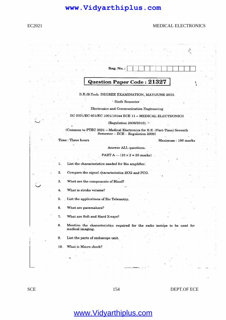
EC2021 MEDICAL ELECTRONICS
SCE 154 DEPT.OF ECE
www.Vidyarthiplus.com
www.Vidyarthiplus.com
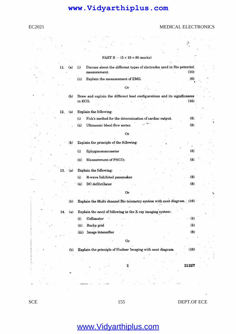
EC2021 MEDICAL ELECTRONICS
SCE 155 DEPT.OF ECE
www.Vidyarthiplus.com
www.Vidyarthiplus.com
EC2021 MEDICAL ELECTRONICS
SCE 156 DEPT.OF ECE
www.Vidyarthiplus.com
www.Vidyarthiplus.com
EC2021 MEDICAL ELECTRONICS
SCE 157 DEPT.OF ECE
www.Vidyarthiplus.com
www.Vidyarthiplus.com
EC2021 MEDICAL ELECTRONICS
SCE 158 DEPT.OF ECE
www.Vidyarthiplus.com
www.Vidyarthiplus.com
EC2021 MEDICAL ELECTRONICS
SCE 159 DEPT.OF ECE
www.Vidyarthiplus.com
www.Vidyarthiplus.com
EC2021 MEDICAL ELECTRONICS
SCE 160 DEPT.OF ECE
www.Vidyarthiplus.com
www.Vidyarthiplus.com
EC2021 MEDICAL ELECTRONICS
SCE 161 DEPT.OF ECE
www.Vidyarthiplus.com
www.Vidyarthiplus.com
EC2021 MEDICAL ELECTRONICS
SCE 162 DEPT.OF ECE
www.Vidyarthiplus.com
www.Vidyarthiplus.com
EC2021 MEDICAL ELECTRONICS
SCE 163 DEPT.OF ECE
www.Vidyarthiplus.com
www.Vidyarthiplus.com


![ECE-VII-POWER ELECTRONICS [10EC73]-NOTES.pdf](https://img.pdfslide.us/doc/110x75/577cc48b1a28aba71199a74d/ece-vii-power-electronics-10ec73-notespdf.jpg)