Embed Size (px)
Citation preview
EVOLUTION®
Medial-Pivot Knee System
S U R G I C A L T E C H N I Q U EDistal Cut First
EVOLUTION®Medial-Pivot Knee System
SURGICAL TECHNIQUEDistal Cut First Instrumentation
Proper surgical procedures and techniques are the responsibility of the medical professional. The following guidelines are furnished for information purposes only. Each surgeon must evaluate the appropriateness of the procedures based on his or her personal medical training and experience.Prior to use of the system, the surgeon should refer to the product package insert for complete warnings, precautions, indications, contraindications and adverse eff ects. Package inserts are also available by contacting Wright Medical Technology, Inc.
Please contact your local Wright representative for product availability.

3
Chapter 1 5 Product Information
6 Indications 6 Contraindications 6 Warnings and Precautions 6 Preoperative Precautions 7 Intraoperative Precautions 8 Postoperative Precautions 9 Adverse Eff ectsChapter 2 10 Surgery Preparation
Chapter 3 11 Surgical Technique
11 Preparation of the Distal Femur 13 Femoral Sizing and Rotation 15 Anterior and Posterior Resections 18 Tibial Preparation 21 Intramedullary Tibial Resection 23 Flexion/Extension Blocks 24 Tibial Sizing, Keel Preparation, and Trial Reduction 27 Trochlear Groove Resection for CS/CR Femoral Components - Sizes 1-2 28 Posterior Stabilized Femoral Housing Resection 29 Trochlear Groove Resection for CS/CR Femoral Components - Sizes 3-8 31 Patella Preparation 33 Trial Reduction and Implant Insertion 33 Trial Reduction 35 2mm Recut Guide, 2° Posterior Slope Recut Guide, and 2° Varus Valgus Recut Guide 35 Re-cutting the Distal Femur 36 Final Implant and Insert Implantation 36 Femoral Implantation 36 Tibial Base Seating 37 Tibial Insert Seating 38 Explant InformationChapter 4 39 Addendum
39 Replaceable Plastic Impaction Surfaces 40 ADVANCE® Patellar Reaming SystemChapter 5 46 Instrument Kit Information
Chapter 6 50 Implant Dimensions
Contents

5
chap
ter
1ProductInformation
Chapter 1 Product Information
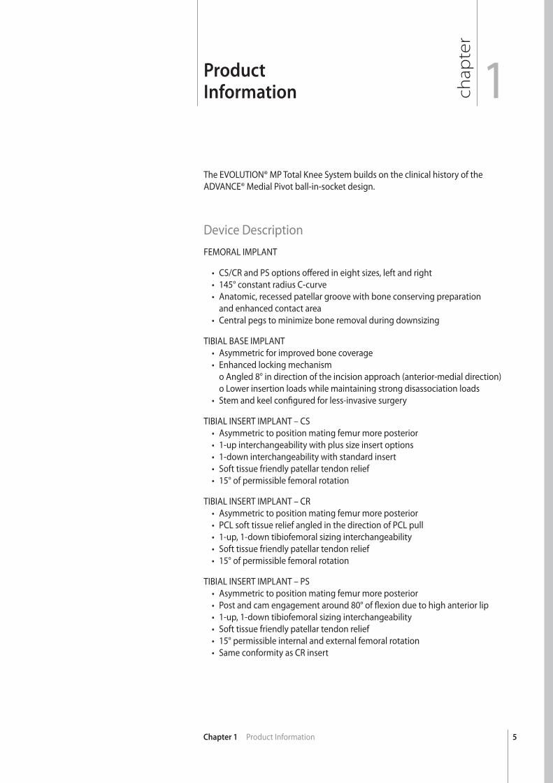
The EVOLUTION® MP Total Knee System builds on the clinical history of the ADVANCE® Medial Pivot ball-in-socket design.
Device DescriptionFEMORAL IMPLANT
• CS/CR and PS options off ered in eight sizes, left and right• 145° constant radius C-curve• Anatomic, recessed patellar groove with bone conserving preparation and enhanced contact area• Central pegs to minimize bone removal during downsizing
TIBIAL BASE IMPLANT• Asymmetric for improved bone coverage• Enhanced locking mechanism o Angled 8° in direction of the incision approach (anterior-medial direction) o Lower insertion loads while maintaining strong disassociation loads• Stem and keel confi gured for less-invasive surgery
TIBIAL INSERT IMPLANT – CS• Asymmetric to position mating femur more posterior• 1-up interchangeability with plus size insert options• 1-down interchangeability with standard insert• Soft tissue friendly patellar tendon relief• 15° of permissible femoral rotation
TIBIAL INSERT IMPLANT – CR• Asymmetric to position mating femur more posterior• PCL soft tissue relief angled in the direction of PCL pull• 1-up, 1-down tibiofemoral sizing interchangeability• Soft tissue friendly patellar tendon relief• 15° of permissible femoral rotation
TIBIAL INSERT IMPLANT – PS• Asymmetric to position mating femur more posterior• Post and cam engagement around 80° of fl exion due to high anterior lip• 1-up, 1-down tibiofemoral sizing interchangeability• Soft tissue friendly patellar tendon relief• 15° permissible internal and external femoral rotation• Same conformity as CR insert
6 Chapter 1 Product Information
Indications The EVOLUTION® Medial-Pivot Knee System is indicated for use in knee arthroplasty in skeletally mature patients with the following conditions:
1) Noninfl ammatory degenerative joint disease including osteoarthritis, traumatic arthritis or avascular necrosis;
2) Infl ammatory degenerative joint disease including rheumatoid arthritis;
3) Correction of functional deformity;
4) Revision procedures where other treatments or devices have failed; and treatment of fractures that are unmanageable using other techniques.
The EVOLUTION® Medial-Pivot Total Knee System is for cemented use only.
Contraindications Patients should be warned of these contraindications. Contraindications include:
1) Overt infection;
2) Distant foci of infections (which may cause hematogeneous spread to the implant site);
3) Rapid disease progression as manifested by joint destruction or bone absorption apparent on roentgenogram;
4) Skeletally immature patients;
5) Cases where there is inadequate neuromuscular status (eg. prior paralysis, fusion and/or inadequate abductor strength), poor bone stock, or poor skin coverage around the joint that would make the procedure unjustifi able.
Warnings and PrecautionsNEVER combine components made by diff erent manufacturers.
Preoperative PrecautionsThe surgeon must evaluate each situation individually based on the patient’s clinical presentation in making any decisions regarding implant selection. The surgeon must be thoroughly familiar with the implant, instruments and surgical procedure prior to performing surgery. The surgeon should contact Wright for product-specifi c surgical techniques.
Patient selection should consider the following factors which could lead to increased risk of failure and can be critical to the eventual success of the procedure: the patient’s weight, activity level and occupation. Additional conditions presenting increased risk of failure include:
1) Uncooperative patient or patient with neurologic disorders, incapable of following instructions;
7Chapter 1 Product Information
2) Marked bone loss, severe osteoporosis, or revision procedures for which an adequate fi t of the prosthesis cannot be achieved;
3) Metabolic disorders that may impair bone formation;
4) Osteomalacia;
5) Poor prognosis for good wound healing (eg. decubitus ulcer, end-stage diabetes, severe protein defi ciency and/or malnutrition).
The patient should be warned of surgical risks and made aware of possible adverse eff ects. The patient should be warned that the prosthesis does not replace normal healthy bone, that the prosthesis can break or become damaged as a result of certain activity or trauma, has a fi nite expected service life and may need to be replaced at some time in the future. The patient should also be advised of other risks that the surgeon believes should be disclosed.
Intraoperative PrecautionsSpecialized instruments are available and must be used to assure the accurate implantation of prosthetic components. Do not mix instruments from diff erent manufacturers. While rare, breakage of instruments may occur especially with extensive use or excessive force. For this reason, instruments should be examined for wear or damage prior to surgery. Inspect devices prior to use for damage during shipment or storage or any out-of-box defects that might increase the likelihood of fragmentation during a procedure.
Correct selection of the prosthesis is important. The potential for success in knee joint replacement is increased by selection of the proper size, shape, and design of the prosthesis. Knee joint prostheses require careful seating and adequate bone support. Smaller sized implants are intended for patients with small bone and normally slight weight. Such components could be inappropriate for other patients. Physicians are encouraged to use their best medical judgment when choosing the proper implant size regardless of the endosteal area of the bone. Preoperative templates and trial prostheses should also be used to assure proper sizing of prostheses. Use only with mating prosthetic components of appropriate size. Mismatching of components could impede component articulation, leading to wear and possible failure of the component and also contribute to joint laxity.
Care is to be taken to ensure complete support of all components of the prosthesis embedded in bone cement to prevent stress concentrations that may lead to failure of the device or cement mantle. Complete cleaning including complete removal of bone chips, bone cement fragments, and metallic debris prior to closure of the prosthetic site is critical to prevent accelerated wear of the articular surfaces of the prosthesis. Modular components must be assembled securely to prevent disassociation. Avoid repeated assembly and disassembly of the modular components that could compromise the locking action of the components. Surgical debris must be cleaned from components before assembly since debris may inhibit the proper fi t and interfere with the locking mechanisms of modular components that may lead to early failure of the procedure. Care should be taken to restore the proper joint alignment and to balance ligamentous tension. Malalignment of the joint can cause excessive wear, loosening of the prosthesis, and pain leading to premature revision of one or more of the prosthetic components.
8 Chapter 1 Product Information
Postoperative PrecautionsThe patient must be advised of the limitations of the reconstruction and theneed for protection of the prosthesis from full weight bearing until adequate fi xation and healing have occurred. Excessive activity and trauma aff ecting the joint replacement have been implicated with failure of the reconstruction by loosening, fracture and/or wear of the prosthetic components. Loosening of the components can result in increased production of wear particles, as well as damage to the bone, making successful revision surgery more diffi cult.Periodic, long-term follow-up is recommended to monitor the position and state of the prosthetic components, as well as the condition of the adjoining bone. Periodic postoperative x-rays are recommended for close comparison with early post-op conditions to detect long term evidence of changes in position, loosening, bending, or cracking of components.
There are inherent risks associated with the use of metallic implants in the MR environment; including component migration, heat induction, and signal interference or distortion near the component(s). Wright knee implants are manufactured from non-magnetic materials; therefore, the risk for migration is low. Heat induction of metallic implants is a risk related to component geometry and material, as well as the MR power, duration, and pulse sequence. Since MR equipment is not standardized, the severity and likelihood of occurrence are unknown for these implants. As with any electrically conductive material, signal interference or distortion of the MR image are likely to occur in proximity to these implants, and therefore caution should be taken when performing measurements around these devices with an MR image.
Wright Knee Systems have not been evaluated for safety and compatibility in the MR environment. Wright Knee Systems have not been tested for heating or migration in the MR environment. Since these devices have not been tested, Wright cannot make a recommendation for the use of MRIs with these implants.
These components are passive metallic devices, and as with all passive devices, there is potential for reciprocal interference with certain imaging modalities; including image distortion for MR and X-ray scatter in CT. Use medical devices in accordance with their labeled indications and Wright Medical Technology’s instructions for use (package insert # 144580), especially during insertion and removal.
Recommendations Regarding Device Fragments:
• Inspect devices immediately upon removal from the patient for any signsof breakage or fragmentation.
• If the device is damaged, retain it to assist with Wright Medical Technology’sanalysis of the event.
• Carefully consider and discuss with the patient (if possible) the risks andbenefi ts of retrieving vs. leaving the fragment in the patient.
• Advise the patient of the nature and safety of unretrieved device fragmentsincluding the following information:
a. The material composition, size, and location of the fragment (if known);
b. The potential mechanisms for injury, e.g., migration, infection;

Chapter 1 Description of Section 9Chapter 1 Product Information
c. Procedures or treatments that should be avoided such as MRI exams in the case of metallic fragments. This may help to reduce the possibility of a serious injury from the fragment.
Adverse Eff ects can include: 1) Osteolysis (progressive bone resorption). Osteolysis can be asymptomatic,
and therefore, routine periodic radiographic examination is vital to preventany serious future complication;
2) Particulate generation leading to increased wear rates necessitating earlyrevision. Soft tissue imbalance leading to excessive wear;
3) Allergic reactions to materials; metal sensitivity that may lead to histologicalreactions;
4) Delayed wound healing; deep wound infection (early or late) which maynecessitate removal of the prosthesis. On rare occasions, arthrodesis of theinvolved joint or amputation of the limb may be required;
5) A sudden drop in blood pressure intraoperatively due to the use of bone cement;
6) Damage to blood vessels or hematoma;
7) Temporary or permanent nerve damage, peripheral neuropathies andsubclinical nerve damage as possible result of surgical trauma resulting in pain or numbness of the aff ected limb;
8) Cardiovascular disorders including venous thrombosis, pulmonary embolism,or myocardial infarction;
9) Dislocation, migration and/or subluxation of prosthetic components fromimproper positioning, trauma, loss of fi xation and/or muscle and fi broustissue laxity;
10) Periarticular calcifi cation or ossifi cation, with or without impediment tojoint mobility;
11) Varus-valgus deformity;
12) Traumatic arthrosis of the knee from intraoperative positioning ofthe extremity;
13) Inadequate range of motion due to improper selection or positioning ofcomponents, periarticular calcifi cation, fl exion contracture;
14) Femoral, tibial or patellar bone or component fracture intraoperatively orpostoperatively; fracture by trauma or excessive loading, particularly in thepresence of poor bone stock;
15) Undesirable shortening or lengthening of the limb;
16) Aggravated problems of the aff ected limb or contralateral extremity by leglength discrepancy, excess femoral medialization, or muscle defi ciency;
17) Pain.
Chapter 1 Description of Section
1chapter
10
ChapterTitle
Chapter 2 Surgery Preparation
2SurgeryPreparation
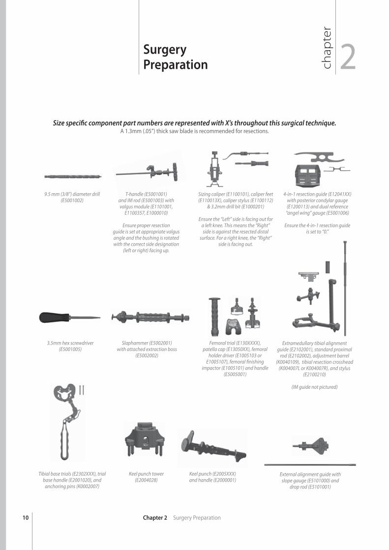
9.5 mm (3/8”) diameter drill (E5001002)
3.5mm hex screwdriver (E5001005)
Tibial base trials (E2302XXX), trial base handle (E2001020), and
anchoring pins (K0002007)
T-handle (E5001001)and IM rod (E5001003) with valgus module (E1101001,
E1100357, E1000010)
Ensure proper resectionguide is set at appropriate valgus angle and the bushing is rotated with the correct side designation
(left or right) facing up.
Slaphammer (E5002001) with attached extraction boss
(E5002002)
Keel punch tower(E2004028)
Sizing caliper (E1100101), caliper feet (E110013X), caliper stylus (E1100112)
& 3.2mm drill bit (E1000201)
Ensure the “Left” side is facing out for a left knee. This means the “Right” side is against the resected distal
surface. For a right knee, the “Right” side is facing out.
Femoral trial (E130XXXX), patella cap (E13050XX), femoral
holder driver (E1005103 or E1005107), femoral fi nishing
impactor (E1005101) and handle (E5005001)
Keel punch (E2005XXX)and handle (E2000001)
4-in-1 resection guide (E12041XX) with posterior condylar gauge(E1200113) and dual reference
“angel wing” gauge (E5001006)
Ensure the 4-in-1 resection guide is set to “0.”
Size specifi c component part numbers are represented with X’s throughout this surgical technique.A 1.3mm (.05”) thick saw blade is recommended for resections.
External alignment guide with slope gauge (E5101000) and
drop rod (E5101001)
Extramedullary tibial alignment guide (E2102001), standard proximal
rod (E2102002), adjustment barrel (K0040109), tibial resection crosshead
(K004007L or K004007R), and stylus (E2100210)
(IM guide not pictured)
11
chap
ter
SurgicalTechnique 3
Chapter 3 Surgical Technique
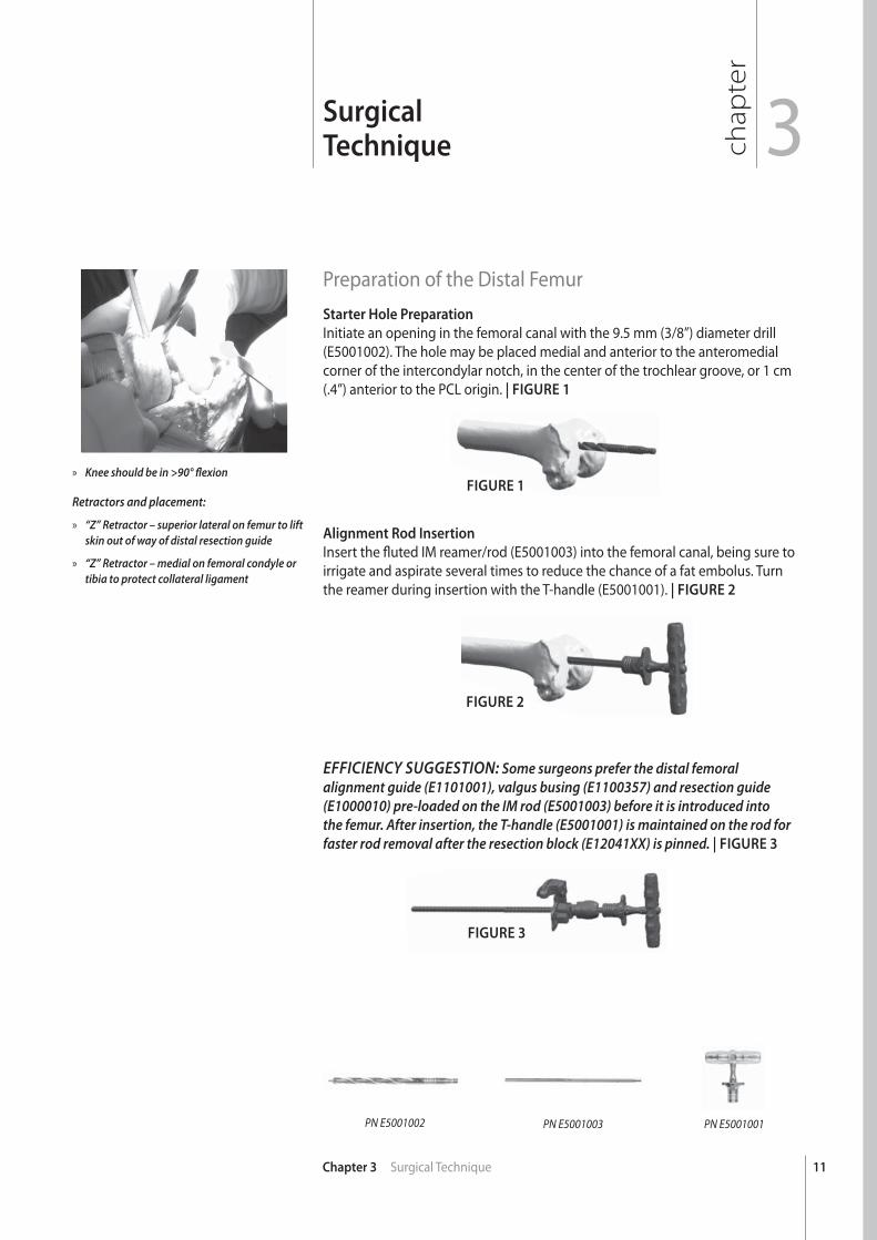
Preparation of the Distal FemurStarter Hole Preparation
Initiate an opening in the femoral canal with the 9.5 mm (3/8”) diameter drill (E5001002). The hole may be placed medial and anterior to the anteromedial corner of the intercondylar notch, in the center of the trochlear groove, or 1 cm (.4”) anterior to the PCL origin. | FIGURE 1
Alignment Rod Insertion
Insert the fl uted IM reamer/rod (E5001003) into the femoral canal, being sure to irrigate and aspirate several times to reduce the chance of a fat embolus. Turn the reamer during insertion with the T-handle (E5001001). | FIGURE 2
FIGURE 1
FIGURE 3
EFFICIENCY SUGGESTION: Some surgeons prefer the distal femoral alignment guide (E1101001), valgus busing (E1100357) and resection guide (E1000010) pre-loaded on the IM rod (E5001003) before it is introduced into the femur. After insertion, the T-handle (E5001001) is maintained on the rod for faster rod removal after the resection block (E12041XX) is pinned. | FIGURE 3
PN E5001002 PN E5001003 PN E5001001
FIGURE 2
» Knee should be in >90° fl exion
Retractors and placement:
» “Z” Retractor – superior lateral on femur to lift skin out of way of distal resection guide
» “Z” Retractor – medial on femoral condyle or tibia to protect collateral ligament
12
A
Chapter 3 Surgical Technique
FIGURE 4
FIGURE 5
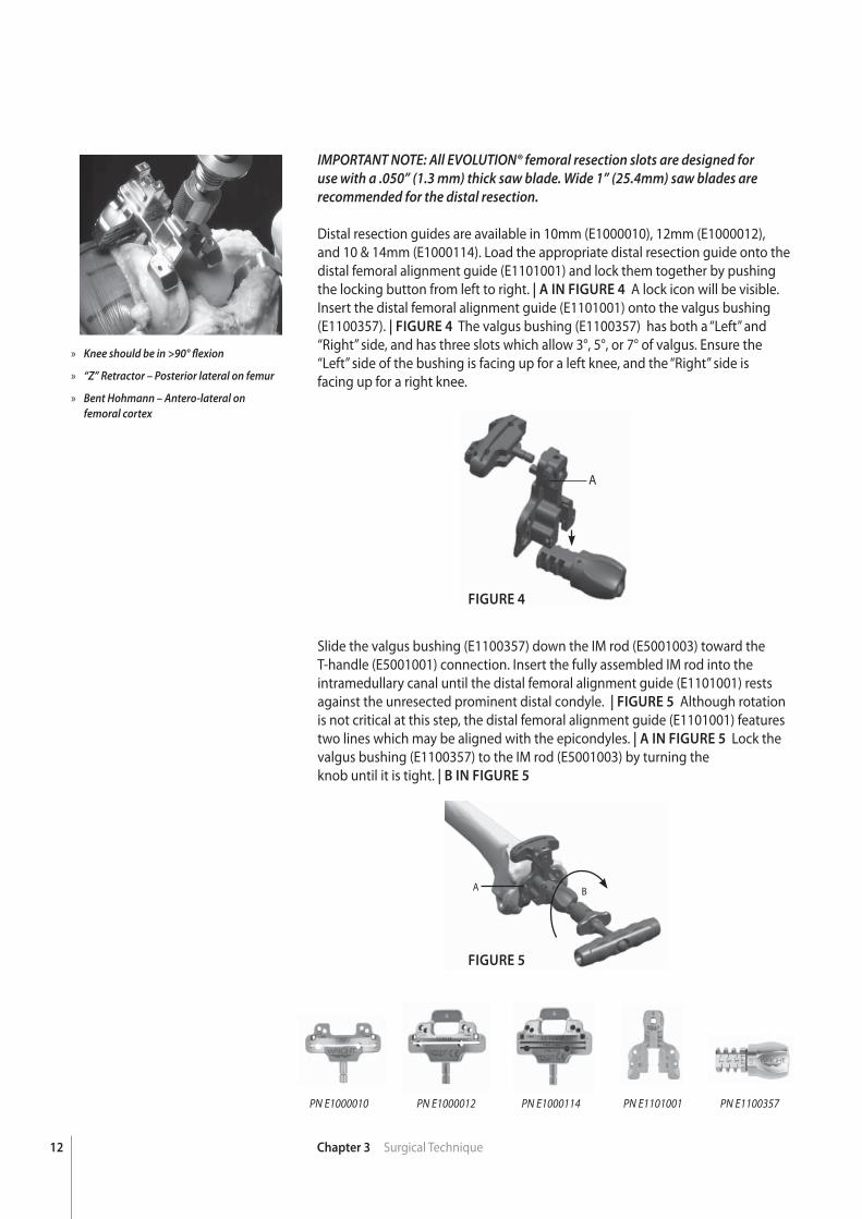
IMPORTANT NOTE: All EVOLUTION® femoral resection slots are designed for use with a .050” (1.3 mm) thick saw blade. Wide 1” (25.4mm) saw blades are recommended for the distal resection.
Distal resection guides are available in 10mm (E1000010), 12mm (E1000012), and 10 & 14mm (E1000114). Load the appropriate distal resection guide onto the distal femoral alignment guide (E1101001) and lock them together by pushing the locking button from left to right. | A IN FIGURE 4 A lock icon will be visible. Insert the distal femoral alignment guide (E1101001) onto the valgus bushing (E1100357). | FIGURE 4 The valgus bushing (E1100357) has both a “Left” and “Right” side, and has three slots which allow 3°, 5°, or 7° of valgus. Ensure the “Left” side of the bushing is facing up for a left knee, and the “Right” side isfacing up for a right knee.
Slide the valgus bushing (E1100357) down the IM rod (E5001003) toward the T-handle (E5001001) connection. Insert the fully assembled IM rod into the intramedullary canal until the distal femoral alignment guide (E1101001) rests against the unresected prominent distal condyle. | FIGURE 5 Although rotation is not critical at this step, the distal femoral alignment guide (E1101001) features two lines which may be aligned with the epicondyles. | A IN FIGURE 5 Lock the valgus bushing (E1100357) to the IM rod (E5001003) by turning theknob until it is tight. | B IN FIGURE 5
PN E1000114PN E1000012PN E1000010 PN E1101001 PN E1100357
A B
» Knee should be in >90° fl exion
» “Z” Retractor – Posterior lateral on femur
» Bent Hohmann – Antero-lateral onfemoral cortex
13Chapter 3 Surgical Technique
FIGURE 6
FIGURE 7
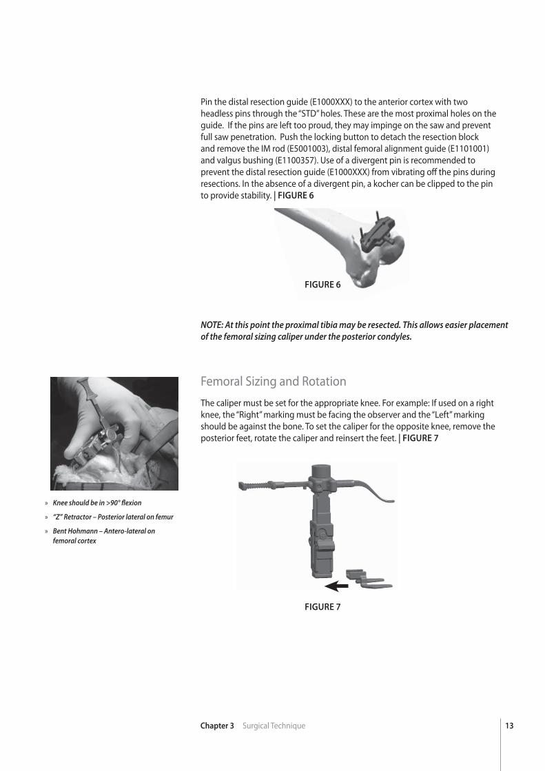
Pin the distal resection guide (E1000XXX) to the anterior cortex with two headless pins through the “STD” holes. These are the most proximal holes on the guide. If the pins are left too proud, they may impinge on the saw and prevent full saw penetration. Push the locking button to detach the resection block and remove the IM rod (E5001003), distal femoral alignment guide (E1101001) and valgus bushing (E1100357). Use of a divergent pin is recommended to prevent the distal resection guide (E1000XXX) from vibrating off the pins during resections. In the absence of a divergent pin, a kocher can be clipped to the pin to provide stability. | FIGURE 6
NOTE: At this point the proximal tibia may be resected. This allows easier placement of the femoral sizing caliper under the posterior condyles.
Femoral Sizing and RotationThe caliper must be set for the appropriate knee. For example: If used on a right knee, the “Right” marking must be facing the observer and the “Left” marking should be against the bone. To set the caliper for the opposite knee, remove the posterior feet, rotate the caliper and reinsert the feet. | FIGURE 7
» Knee should be in >90° fl exion
» “Z” Retractor – Posterior lateral on femur
» Bent Hohmann – Antero-lateral onfemoral cortex
14 Chapter 3 Surgical Technique
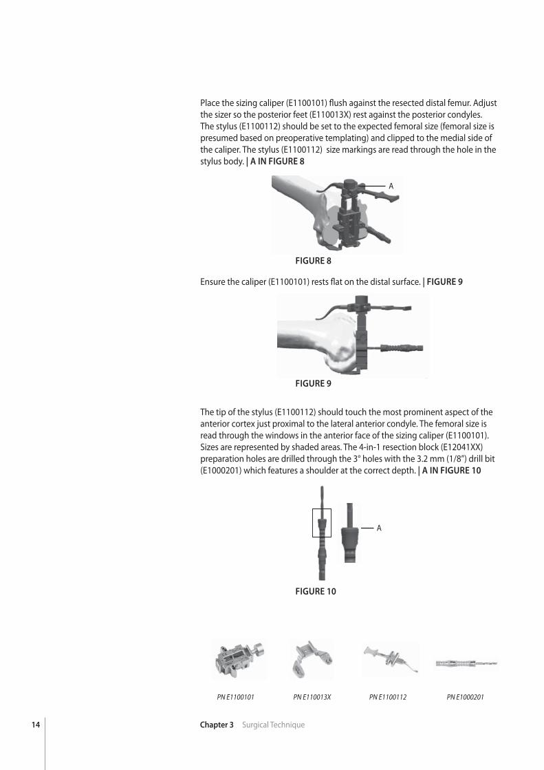
Place the sizing caliper (E1100101) fl ush against the resected distal femur. Adjust the sizer so the posterior feet (E110013X) rest against the posterior condyles. The stylus (E1100112) should be set to the expected femoral size (femoral size is presumed based on preoperative templating) and clipped to the medial side of the caliper. The stylus (E1100112) size markings are read through the hole in the stylus body. | A IN FIGURE 8
PN E1100101 PN E110013X PN E1000201PN E1100112
FIGURE 8
FIGURE 9
FIGURE 10
A
Ensure the caliper (E1100101) rests fl at on the distal surface. | FIGURE 9
The tip of the stylus (E1100112) should touch the most prominent aspect of the anterior cortex just proximal to the lateral anterior condyle. The femoral size is read through the windows in the anterior face of the sizing caliper (E1100101). Sizes are represented by shaded areas. The 4-in-1 resection block (E12041XX) preparation holes are drilled through the 3° holes with the 3.2 mm (1/8”) drill bit (E1000201) which features a shoulder at the correct depth. | A IN FIGURE 10
A
15Chapter 3 Surgical Technique
» Curved single-prong Hohmann – Superior-lateral on femoral cortex
» “Z” Retractor – Posterior lateral on femur
» “Z” Retractor – Posterior medial on femur to protect medial collateral ligament
FIGURE 11
FIGURE 12
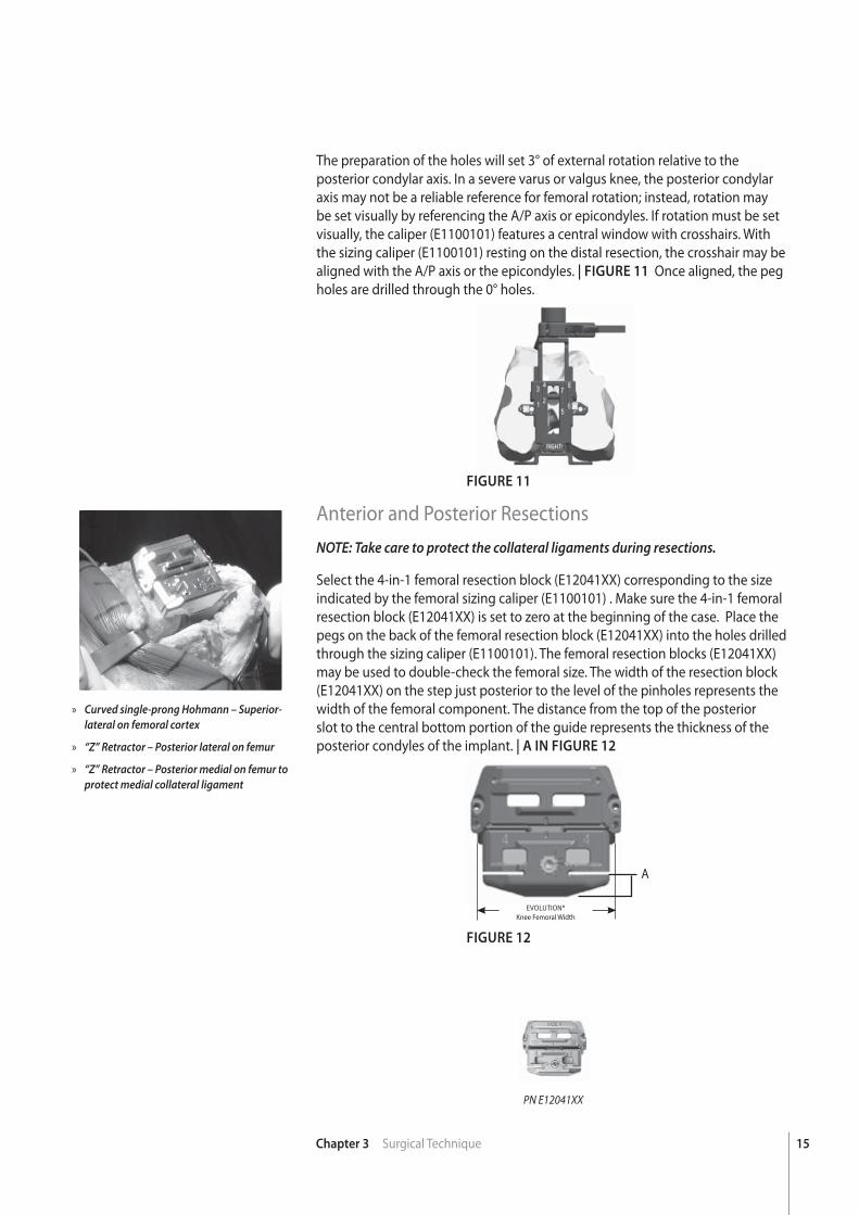
The preparation of the holes will set 3° of external rotation relative to the posterior condylar axis. In a severe varus or valgus knee, the posterior condylar axis may not be a reliable reference for femoral rotation; instead, rotation may be set visually by referencing the A/P axis or epicondyles. If rotation must be set visually, the caliper (E1100101) features a central window with crosshairs. With the sizing caliper (E1100101) resting on the distal resection, the crosshair may be aligned with the A/P axis or the epicondyles. | FIGURE 11 Once aligned, the peg holes are drilled through the 0° holes.
Anterior and Posterior ResectionsNOTE: Take care to protect the collateral ligaments during resections.
Select the 4-in-1 femoral resection block (E12041XX) corresponding to the size indicated by the femoral sizing caliper (E1100101) . Make sure the 4-in-1 femoral resection block (E12041XX) is set to zero at the beginning of the case. Place the pegs on the back of the femoral resection block (E12041XX) into the holes drilled through the sizing caliper (E1100101). The femoral resection blocks (E12041XX) may be used to double-check the femoral size. The width of the resection block (E12041XX) on the step just posterior to the level of the pinholes represents the width of the femoral component. The distance from the top of the posterior slot to the central bottom portion of the guide represents the thickness of the posterior condyles of the implant. | A IN FIGURE 12
A
EVOLUTION® Knee Femoral Width
PN E12041XX
16 Chapter 3 Surgical Technique
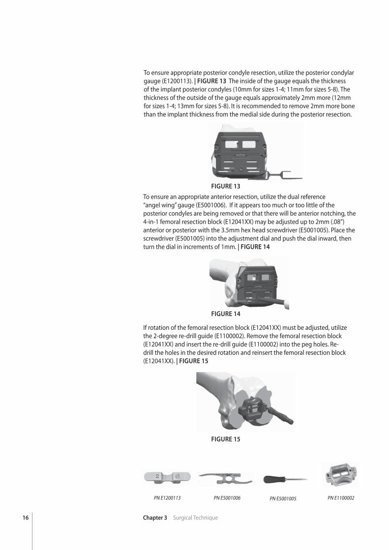
To ensure appropriate posterior condyle resection, utilize the posterior condylar gauge (E1200113). | FIGURE 13 The inside of the gauge equals the thickness of the implant posterior condyles (10mm for sizes 1-4; 11mm for sizes 5-8). The thickness of the outside of the gauge equals approximately 2mm more (12mm for sizes 1-4; 13mm for sizes 5-8). It is recommended to remove 2mm more bone than the implant thickness from the medial side during the posterior resection.
PN E5001006PN E1200113 PN E1100002
FIGURE 13
FIGURE 14
FIGURE 15
To ensure an appropriate anterior resection, utilize the dual reference“angel wing” gauge (E5001006). If it appears too much or too little of the posterior condyles are being removed or that there will be anterior notching, the4-in-1 femoral resection block (E12041XX) may be adjusted up to 2mm (.08”) anterior or posterior with the 3.5mm hex head screwdriver (E5001005). Place the screwdriver (E5001005) into the adjustment dial and push the dial inward, then turn the dial in increments of 1mm. | FIGURE 14
If rotation of the femoral resection block (E12041XX) must be adjusted, utilize the 2-degree re-drill guide (E1100002). Remove the femoral resection block (E12041XX) and insert the re-drill guide (E1100002) into the peg holes. Re-drill the holes in the desired rotation and reinsert the femoral resection block (E12041XX). | FIGURE 15
PN E5001005
17Chapter 3 Surgical Technique
PN E5002001 PN E5002002
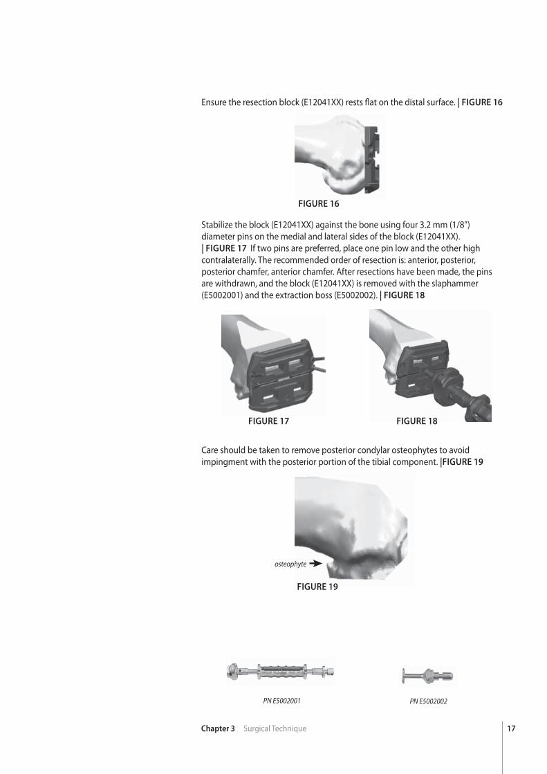
Ensure the resection block (E12041XX) rests fl at on the distal surface. | FIGURE 16
FIGURE 16
FIGURE 17 FIGURE 18
Stabilize the block (E12041XX) against the bone using four 3.2 mm (1/8”) diameter pins on the medial and lateral sides of the block (E12041XX).| FIGURE 17 If two pins are preferred, place one pin low and the other high contralaterally. The recommended order of resection is: anterior, posterior, posterior chamfer, anterior chamfer. After resections have been made, the pins are withdrawn, and the block (E12041XX) is removed with the slaphammer (E5002001) and the extraction boss (E5002002). | FIGURE 18
Care should be taken to remove posterior condylar osteophytes to avoid impingment with the posterior portion of the tibial component. |FIGURE 19
osteophyte
FIGURE 19
18 Chapter 3 Surgical Technique
Tibial PreparationThe EVOLUTION® tibial resection guides are designed for use with a 1.3 mm(.05”) thick saw blade.
Extramedullary Tibial Resection
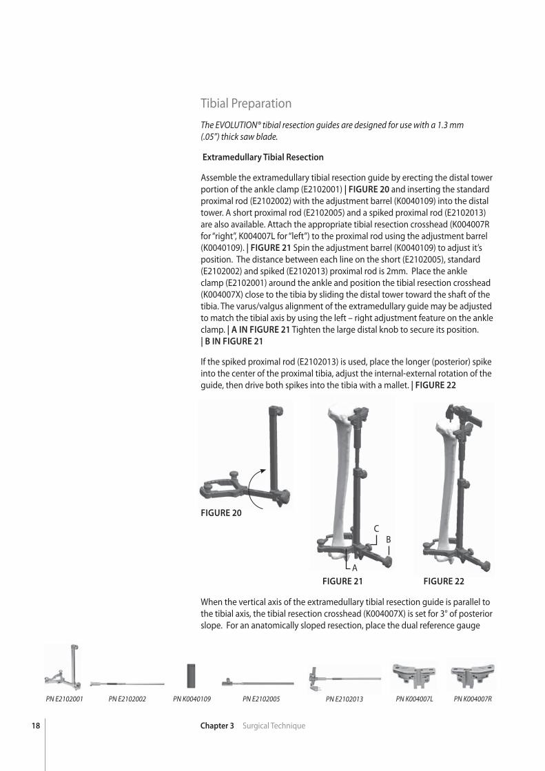
Assemble the extramedullary tibial resection guide by erecting the distal tower portion of the ankle clamp (E2102001) | FIGURE 20 and inserting the standard proximal rod (E2102002) with the adjustment barrel (K0040109) into the distal tower. A short proximal rod (E2102005) and a spiked proximal rod (E2102013) are also available. Attach the appropriate tibial resection crosshead (K004007R for “right”, K004007L for “left”) to the proximal rod using the adjustment barrel (K0040109). | FIGURE 21 Spin the adjustment barrel (K0040109) to adjust it’s position. The distance between each line on the short (E2102005), standard (E2102002) and spiked (E2102013) proximal rod is 2mm. Place the ankle clamp (E2102001) around the ankle and position the tibial resection crosshead (K004007X) close to the tibia by sliding the distal tower toward the shaft of the tibia. The varus/valgus alignment of the extramedullary guide may be adjusted to match the tibial axis by using the left – right adjustment feature on the ankle clamp. | A IN FIGURE 21 Tighten the large distal knob to secure its position.| B IN FIGURE 21
If the spiked proximal rod (E2102013) is used, place the longer (posterior) spike into the center of the proximal tibia, adjust the internal-external rotation of the guide, then drive both spikes into the tibia with a mallet. | FIGURE 22
PN K004007LPN E2102005PN K0040109PN E2102002PN E2102001 PN K004007RPN E2102013
FIGURE 20
When the vertical axis of the extramedullary tibial resection guide is parallel to the tibial axis, the tibial resection crosshead (K004007X) is set for 3° of posterior slope. For an anatomically sloped resection, place the dual reference gauge
FIGURE 21 FIGURE 22
A
BC
19Chapter 3 Surgical Technique
FIGURE 23 FIGURE 24 FIGURE 25
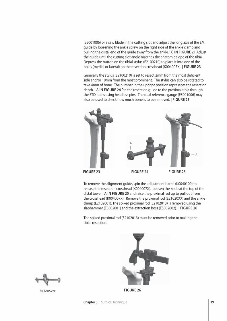
(E5001006) or a saw blade in the cutting slot and adjust the long axis of the EM guide by loosening the ankle screw on the right side of the ankle clamp and pulling the distal end of the guide away from the ankle. | C IN FIGURE 21 Adjust the guide until the cutting slot angle matches the anatomic slope of the tibia. Depress the button on the tibial stylus (E2100210) to place it into one of the holes (medial or lateral) on the resection crosshead (K004007X). | FIGURE 23
Generally the stylus (E2100210) is set to resect 2mm from the most defi cient side and/or 10mm from the most prominent. The stylus can also be rotated to take 4mm of bone. The number in the upright position represents the resection depth. | A IN FIGURE 24 Pin the resection guide to the proximal tibia through the STD holes using headless pins. The dual reference gauge (E5001006) may also be used to check how much bone is to be removed. | FIGURE 25
To remove the alignment guide, spin the adjustment barrel (K0040109) to release the resection crosshead (K004007X). Loosen the knob at the top of the distal tower | A IN FIGURE 25 and raise the proximal rod up to pull out from the crosshead (K004007X). Remove the proximal rod (E21020XX) and the ankle clamp (E2102001). The spiked proximal rod (E2102013) is removed using the slaphammer (E5002001) and the extraction boss (E5002002). | FIGURE 26
The spiked proximal rod (E2102013) must be removed prior to making thetibial resection.
PN E2100210
A
A
FIGURE 26
20 Chapter 3 Surgical Technique
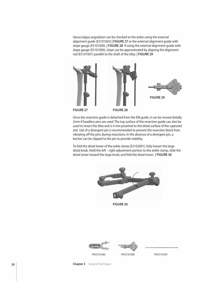
Varus/valgus angulation can be checked to the ankle using the external alignment guide (E5101002) | FIGURE 27 or the external alignment guide with slope gauge (E5101000). | FIGURE 28 If using the external alignment guide with slope gauge (E5101000), slope can be approximated by aligning the alignment rod (E5101001) parallel to the shaft of the tibia. | FIGURE 29
FIGURE 27 FIGURE 28
FIGURE 30
FIGURE 29
Once the resection guide is detached from the EM guide, it can be moved distally 2mm if headless pins are used. The top surface of the resection guide can also be used to resect the tibia and is 4 mm proximal to the distal surface of the captured slot. Use of a divergent pin is recommended to prevent the resection block from vibrating off the pins during resections. In the absence of a divergent pin, a kocher can be clipped to the pin to provide stability.
To fold the distal tower of the ankle clamp (E2102001), fully loosen the large distal knob. Hold the left – right adjustment portion to the ankle clamp, slide the distal tower toward the large knob, and fold the distal tower. | FIGURE 30
PN E5101000PN E5101002 PN E5101001
21Chapter 3 Surgical Technique
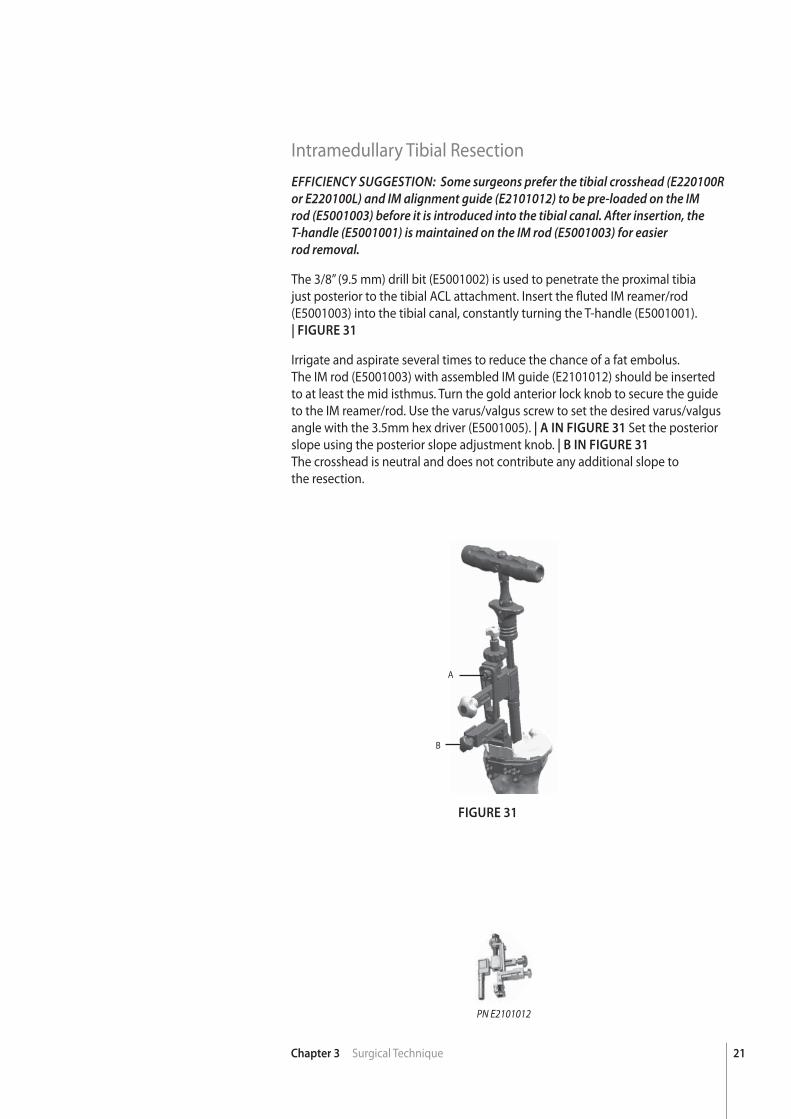
Intramedullary Tibial ResectionEFFICIENCY SUGGESTION: Some surgeons prefer the tibial crosshead (E220100R or E220100L) and IM alignment guide (E2101012) to be pre-loaded on the IM rod (E5001003) before it is introduced into the tibial canal. After insertion, the T-handle (E5001001) is maintained on the IM rod (E5001003) for easierrod removal.
The 3/8” (9.5 mm) drill bit (E5001002) is used to penetrate the proximal tibia just posterior to the tibial ACL attachment. Insert the fl uted IM reamer/rod (E5001003) into the tibial canal, constantly turning the T-handle (E5001001).| FIGURE 31
Irrigate and aspirate several times to reduce the chance of a fat embolus.The IM rod (E5001003) with assembled IM guide (E2101012) should be inserted to at least the mid isthmus. Turn the gold anterior lock knob to secure the guide to the IM reamer/rod. Use the varus/valgus screw to set the desired varus/valgus angle with the 3.5mm hex driver (E5001005). | A IN FIGURE 31 Set the posterior slope using the posterior slope adjustment knob. | B IN FIGURE 31
The crosshead is neutral and does not contribute any additional slope tothe resection.
FIGURE 31
PN E2101012
A
B
22 Chapter 3 Surgical Technique
FIGURE 33 FIGURE 34FIGURE 32
PN E2100210 PN E220100LPN E220100R
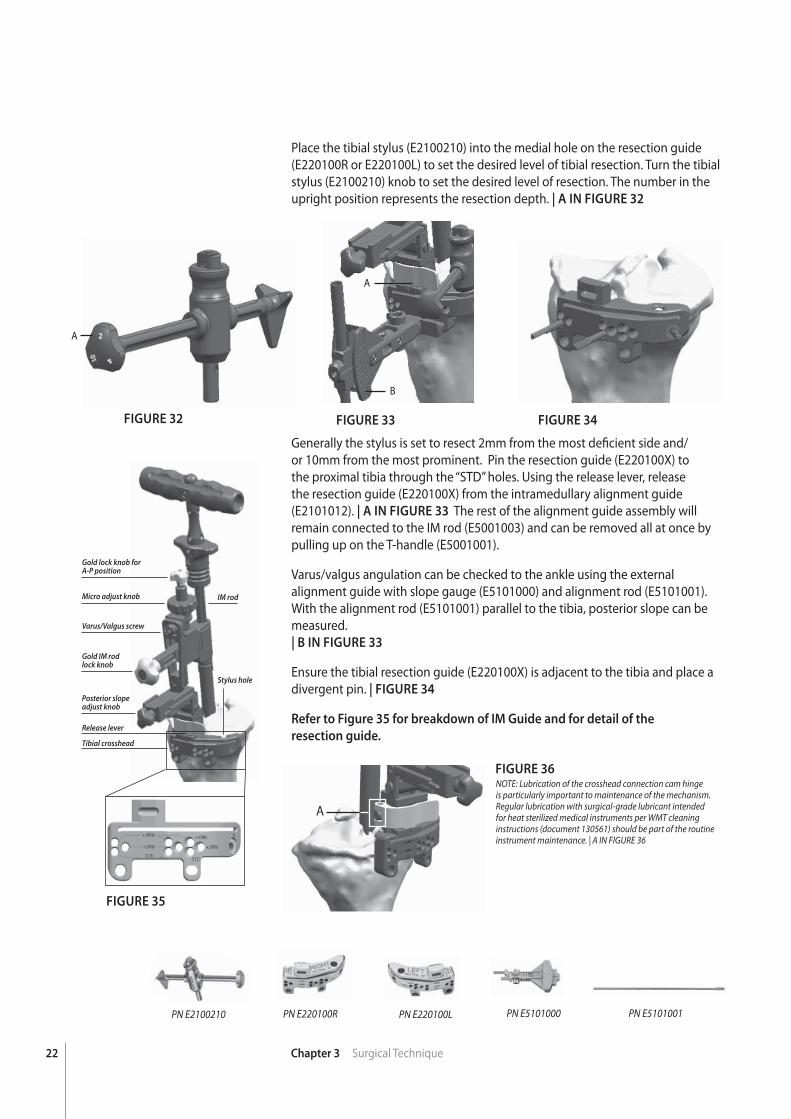
Place the tibial stylus (E2100210) into the medial hole on the resection guide (E220100R or E220100L) to set the desired level of tibial resection. Turn the tibial stylus (E2100210) knob to set the desired level of resection. The number in the upright position represents the resection depth. | A IN FIGURE 32
Generally the stylus is set to resect 2mm from the most defi cient side and/or 10mm from the most prominent. Pin the resection guide (E220100X) to the proximal tibia through the “STD” holes. Using the release lever, release the resection guide (E220100X) from the intramedullary alignment guide (E2101012). | A IN FIGURE 33 The rest of the alignment guide assembly will remain connected to the IM rod (E5001003) and can be removed all at once by pulling up on the T-handle (E5001001).
Varus/valgus angulation can be checked to the ankle using the external alignment guide with slope gauge (E5101000) and alignment rod (E5101001). With the alignment rod (E5101001) parallel to the tibia, posterior slope can be measured. | B IN FIGURE 33
Ensure the tibial resection guide (E220100X) is adjacent to the tibia and place a divergent pin. | FIGURE 34
Refer to Figure 35 for breakdown of IM Guide and for detail of the
resection guide.
A
B
A
PN E5101000 PN E5101001
FIGURE 35
FIGURE 36
Gold IM rodlock knob
Posterior slope adjust knob
Stylus hole
IM rodMicro adjust knob
Gold lock knob for A-P position
Varus/Valgus screw
Tibial crosshead
Release lever
A
NOTE: Lubrication of the crosshead connection cam hinge is particularly important to maintenance of the mechanism. Regular lubrication with surgical-grade lubricant intended for heat sterilized medical instruments per WMT cleaning instructions (document 130561) should be part of the routine instrument maintenance. | A IN FIGURE 36
23Chapter 3 Surgical Technique
Flexion/Extension BlocksFlexion/Extension blocks are not part of the standard kit. They can be ordered
under kit # E200KT20.
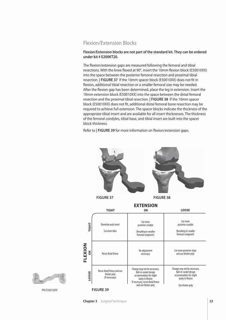
The fl exion/extension gaps are measured following the femoral and tibial resections. With the knee fl exed at 90°, insert the 10mm fl exion block (E50010XX) into the space between the posterior femoral resection and proximal tibial resection. | FIGURE 37 If the 10mm spacer block (E50010XX) does not fi t in fl exion, additional tibial resection or a smaller femoral size may be needed. After the fl exion gap has been determined, place the leg in extension. Insert the 10mm extension block (E50010XX) into the space between the distal femoral resection and the proximal tibial resection. | FIGURE 38 If the 10mm spacer block (E50010XX) does not fi t, additional distal femoral bone resection may be required to achieve full extension. The spacer blocks indicate the thickness of the appropriate tibial insert and are available for all insert thicknesses. The thickness of the femoral condyles, tibial base, and tibial insert are built into the spacer block thickness.
Refer to | FIGURE 39 for more information on fl exion/extension gaps.
FIGURE 37
FIGURE 39
FIGURE 38
PN E50010XX
EXTENSION
FL
EX
ION
OK
OK
TIGHT
TIG
HT
LOOSE
LO
OS
E
Downsize poly insert
Cut more tibia
Recut distal femur
Recut distal femur and use thicker poly
(If necessary)
Cut moreposterior condyle
(Resulting in smallerfemoral componet)
Change may not be necessary. Ball-in-socket design
accommodates for slight laxity in fl exion
If necessary, recut distal femur and use thicker poly
Change may not be necessary. Ball-in-socket design
accommodates for slight laxity in fl exion
Use thicker poly
No adjustmentnecessary
Cut moreposterior condyle
(Resulting in smallerfemoral componet)
Cut more posterior slopeand use thicker poly
24 Chapter 3 Surgical Technique
FIGURE 40
FIGURE 41
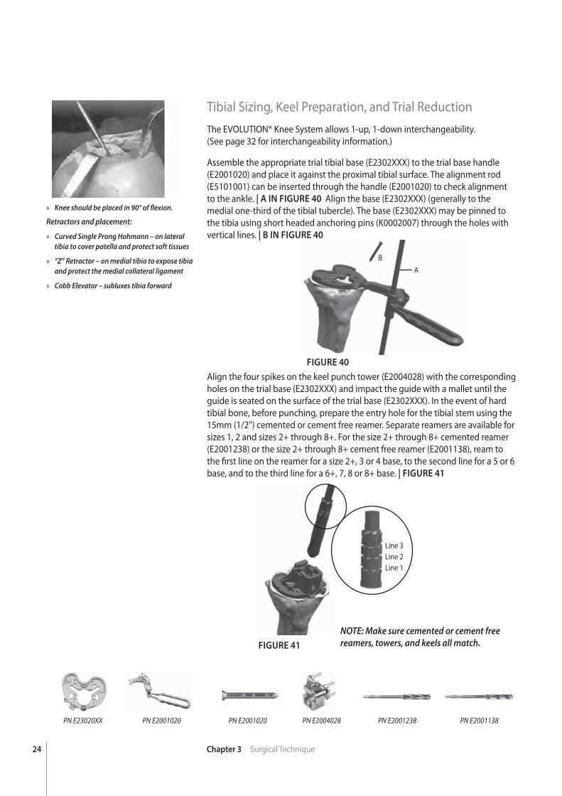
Tibial Sizing, Keel Preparation, and Trial ReductionThe EVOLUTION® Knee System allows 1-up, 1-down interchangeability.(See page 32 for interchangeability information.)
Assemble the appropriate trial tibial base (E2302XXX) to the trial base handle (E2001020) and place it against the proximal tibial surface. The alignment rod (E5101001) can be inserted through the handle (E2001020) to check alignment to the ankle. | A IN FIGURE 40 Align the base (E2302XXX) (generally to the medial one-third of the tibial tubercle). The base (E2302XXX) may be pinned to the tibia using short headed anchoring pins (K0002007) through the holes with vertical lines. | B IN FIGURE 40
Align the four spikes on the keel punch tower (E2004028) with the corresponding holes on the trial base (E2302XXX) and impact the guide with a mallet until the guide is seated on the surface of the trial base (E2302XXX). In the event of hard tibial bone, before punching, prepare the entry hole for the tibial stem using the 15mm (1/2”) cemented or cement free reamer. Separate reamers are available for sizes 1, 2 and sizes 2+ through 8+. For the size 2+ through 8+ cemented reamer (E2001238) or the size 2+ through 8+ cement free reamer (E2001138), ream to the fi rst line on the reamer for a size 2+, 3 or 4 base, to the second line for a 5 or 6 base, and to the third line for a 6+, 7, 8 or 8+ base. | FIGURE 41
PN E23020XX PN E2004028PN E2001020 PN E2001020 PN E2001238 PN E2001138
Line 3Line 2Line 1
» Knee should be placed in 90° of fl exion.
Retractors and placement:
» Curved Single Prong Hohmann – on lateral tibia to cover patella and protect soft tissues
» “Z” Retractor – on medial tibia to expose tibia and protect the medial collateral ligament
» Cobb Elevator – subluxes tibia forward
A
B
NOTE: Make sure cemented or cement free reamers, towers, and keels all match.
25Chapter 3 Surgical Technique
FIGURE 42 FIGURE 43
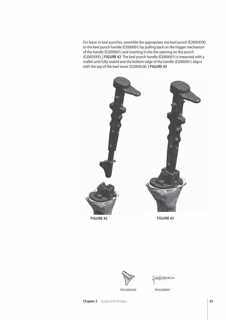
For leave-in keel punches, assemble the appropriate size keel punch (E2005XXX) to the keel punch handle (E2000001) by pulling back on the trigger mechanism of the handle (E2000001) and inserting it into the opening on the punch (E2005XXX). | FIGURE 42 The keel punch handle (E2000001) is impacted with a mallet until fully seated and the bottom edge of the handle (E2000001) aligns with the top of the keel tower (E2004028). | FIGURE 43
PN E2005XXX PN E2000001
26 Chapter 3 Surgical Technique
FIGURE 44 FIGURE 45 FIGURE 46
PN E5002003
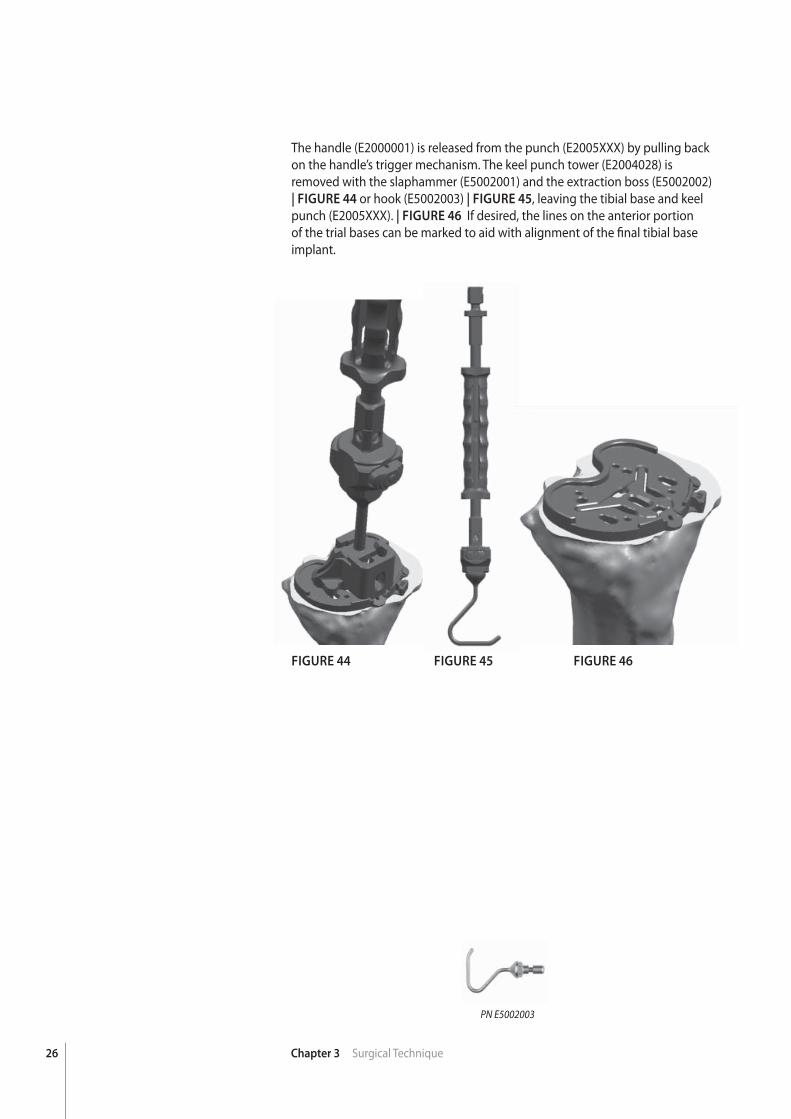
The handle (E2000001) is released from the punch (E2005XXX) by pulling back on the handle’s trigger mechanism. The keel punch tower (E2004028) isremoved with the slaphammer (E5002001) and the extraction boss (E5002002) | FIGURE 44 or hook (E5002003) | FIGURE 45, leaving the tibial base and keel punch (E2005XXX). | FIGURE 46 If desired, the lines on the anterior portion of the trial bases can be marked to aid with alignment of the fi nal tibial base implant.
27Chapter 3 Surgical Technique
Trochlear Groove Resection for CS/CR Femoral Components (Sizes 1-2)The trochlear groove resection for sizes 3-8 CS/CR femoral components is
made through the femoral trial and is performed after the tibial bone has
been prepared.
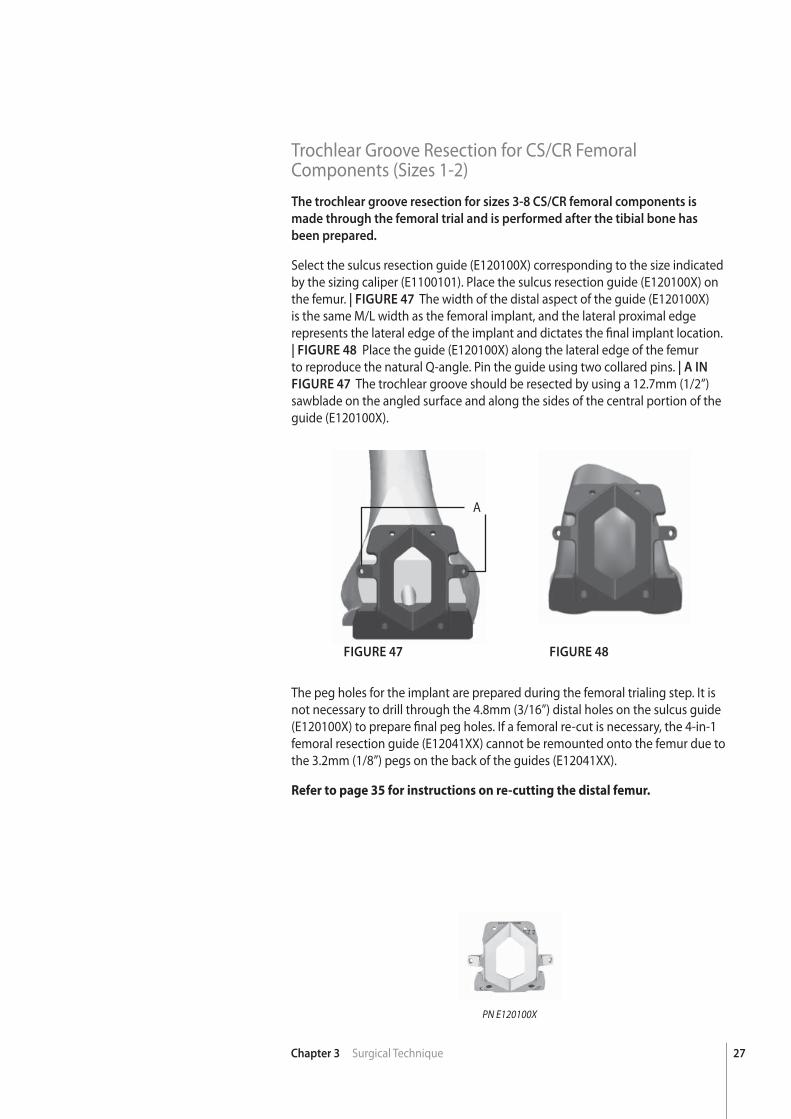
Select the sulcus resection guide (E120100X) corresponding to the size indicated by the sizing caliper (E1100101). Place the sulcus resection guide (E120100X) on the femur. | FIGURE 47 The width of the distal aspect of the guide (E120100X) is the same M/L width as the femoral implant, and the lateral proximal edge represents the lateral edge of the implant and dictates the fi nal implant location. | FIGURE 48 Place the guide (E120100X) along the lateral edge of the femur to reproduce the natural Q-angle. Pin the guide using two collared pins. | A IN
FIGURE 47 The trochlear groove should be resected by using a 12.7mm (1/2”) sawblade on the angled surface and along the sides of the central portion of the guide (E120100X).
FIGURE 47 FIGURE 48
PN E120100X
The peg holes for the implant are prepared during the femoral trialing step. It is not necessary to drill through the 4.8mm (3/16”) distal holes on the sulcus guide (E120100X) to prepare fi nal peg holes. If a femoral re-cut is necessary, the 4-in-1 femoral resection guide (E12041XX) cannot be remounted onto the femur due to the 3.2mm (1/8”) pegs on the back of the guides (E12041XX).
Refer to page 35 for instructions on re-cutting the distal femur.
A
28 Chapter 3 Surgical Technique
FIGURE 49
PN E120510X
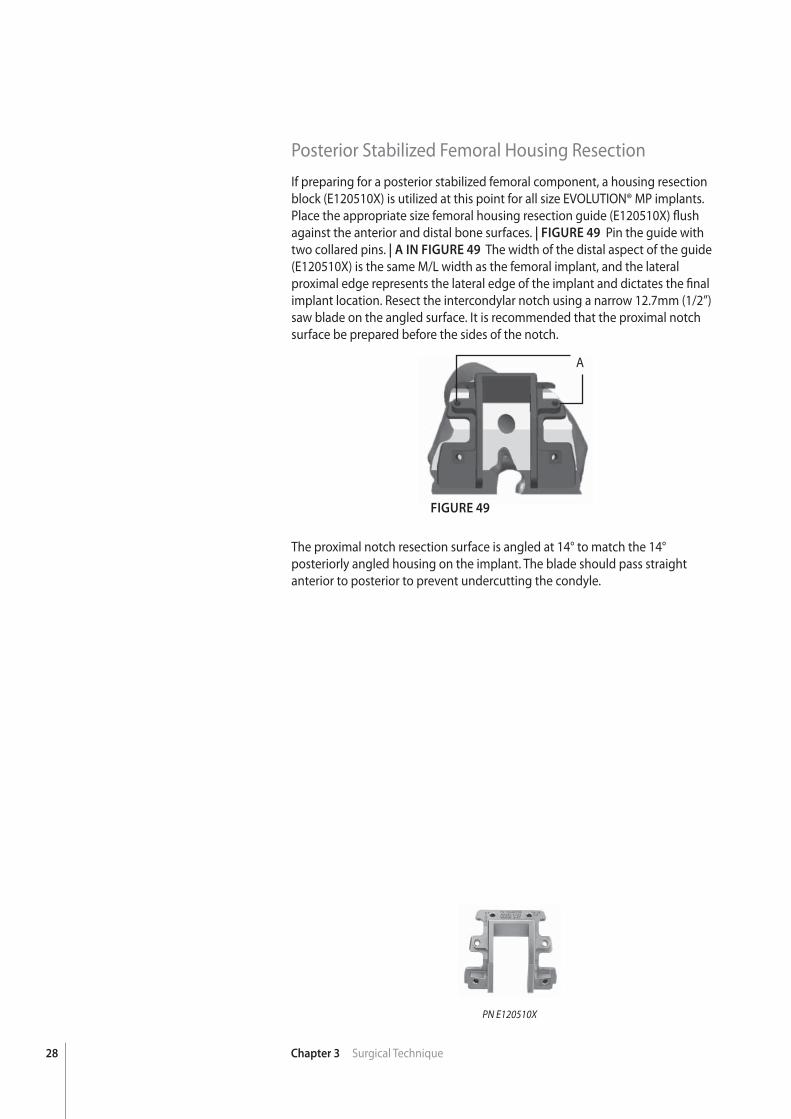
Posterior Stabilized Femoral Housing ResectionIf preparing for a posterior stabilized femoral component, a housing resection block (E120510X) is utilized at this point for all size EVOLUTION® MP implants. Place the appropriate size femoral housing resection guide (E120510X) fl ush against the anterior and distal bone surfaces. | FIGURE 49 Pin the guide with two collared pins. | A IN FIGURE 49 The width of the distal aspect of the guide (E120510X) is the same M/L width as the femoral implant, and the lateral proximal edge represents the lateral edge of the implant and dictates the fi nal implant location. Resect the intercondylar notch using a narrow 12.7mm (1/2”) saw blade on the angled surface. It is recommended that the proximal notch surface be prepared before the sides of the notch.
The proximal notch resection surface is angled at 14° to match the 14° posteriorly angled housing on the implant. The blade should pass straight anterior to posterior to prevent undercutting the condyle.
A
29Chapter 3 Surgical Technique
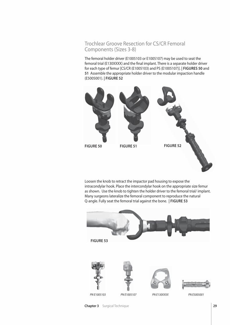
Trochlear Groove Resection for CS/CR Femoral Components (Sizes 3-8)The femoral holder driver (E1005103 or E1005107) may be used to seat the femoral trial (E130XXXX) and the fi nal implant. There is a separate holder driver for each type of femur [CS/CR (E1005103) and PS (E1005107)]. | FIGURES 50 and 51 Assemble the appropriate holder driver to the modular impaction handle (E5005001). | FIGURE 52
FIGURE 50 FIGURE 51 FIGURE 52
FIGURE 53
PN E1005103 PN E1005107 PN E5005001PN E130XXXX
Loosen the knob to retract the impactor pad housing to expose the intracondylar hook. Place the intercondylar hook on the appropriate size femur as shown. Use the knob to tighten the holder driver to the femoral trial/ implant. Many surgeons lateralize the femoral component to reproduce the natural Q-angle. Fully seat the femoral trial against the bone. | FIGURE 53
30 Chapter 3 Surgical Technique
FIGURE 54 FIGURE 55
FIGURE 56 FIGURE 57
PN E1005101 PN E1000301 PN E1051022
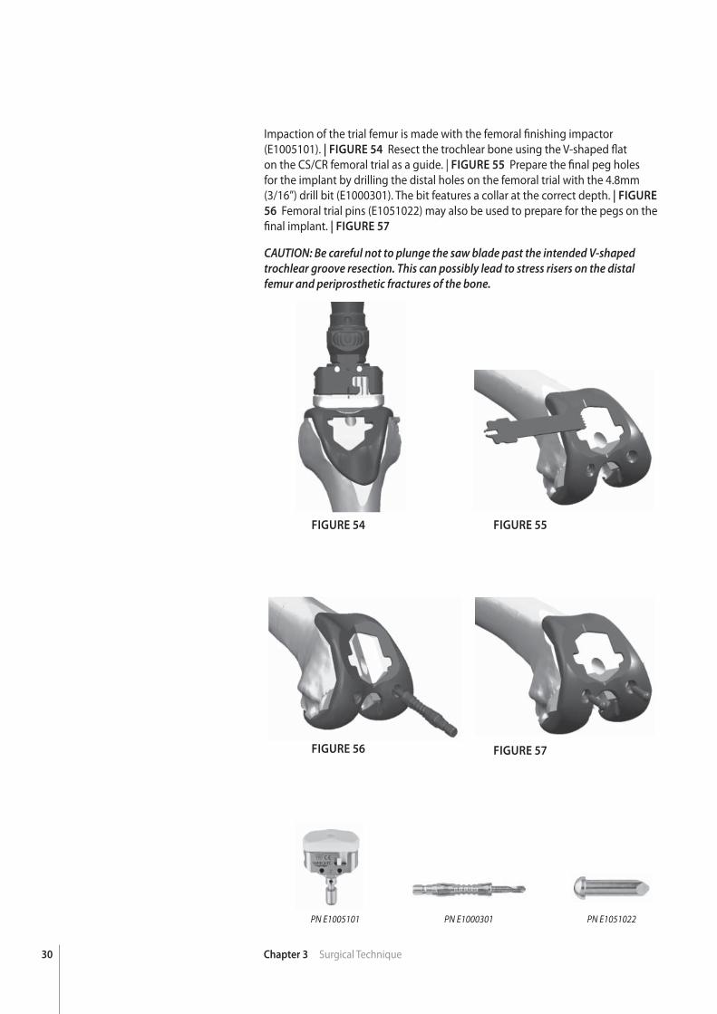
Impaction of the trial femur is made with the femoral fi nishing impactor (E1005101). | FIGURE 54 Resect the trochlear bone using the V-shaped fl at on the CS/CR femoral trial as a guide. | FIGURE 55 Prepare the fi nal peg holes for the implant by drilling the distal holes on the femoral trial with the 4.8mm (3/16”) drill bit (E1000301). The bit features a collar at the correct depth. | FIGURE
56 Femoral trial pins (E1051022) may also be used to prepare for the pegs on the fi nal implant. | FIGURE 57
CAUTION: Be careful not to plunge the saw blade past the intended V-shaped trochlear groove resection. This can possibly lead to stress risers on the distal femur and periprosthetic fractures of the bone.
31Chapter 3 Surgical Technique
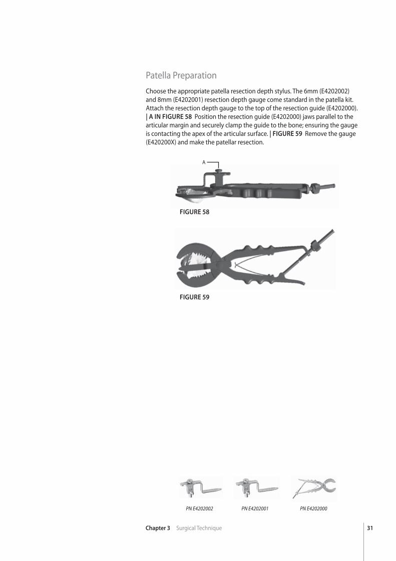
Patella PreparationChoose the appropriate patella resection depth stylus. The 6mm (E4202002) and 8mm (E4202001) resection depth gauge come standard in the patella kit. Attach the resection depth gauge to the top of the resection guide (E4202000). | A IN FIGURE 58 Position the resection guide (E4202000) jaws parallel to the articular margin and securely clamp the guide to the bone; ensuring the gauge is contacting the apex of the articular surface. | FIGURE 59 Remove the gauge (E420200X) and make the patellar resection.
FIGURE 58
FIGURE 59
PN E4202000PN E4202001PN E4202002
A
32 Chapter 3 Surgical Technique
FIGURE 60
FIGURE 61
PN K0031109 PN E4001015PN K0031104 PN E4001035PN K0031103 PN E4001008
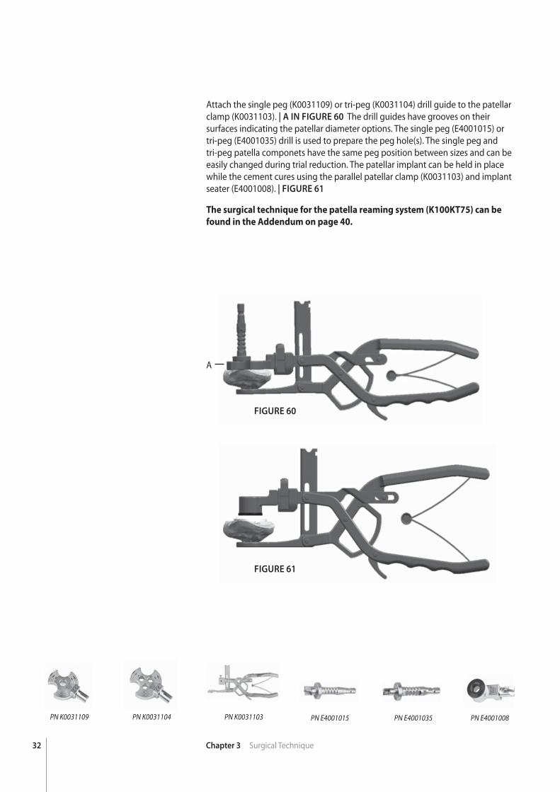
Attach the single peg (K0031109) or tri-peg (K0031104) drill guide to the patellar clamp (K0031103). | A IN FIGURE 60 The drill guides have grooves on their surfaces indicating the patellar diameter options. The single peg (E4001015) or tri-peg (E4001035) drill is used to prepare the peg hole(s). The single peg and tri-peg patella componets have the same peg position between sizes and can be easily changed during trial reduction. The patellar implant can be held in place while the cement cures using the parallel patellar clamp (K0031103) and implant seater (E4001008). | FIGURE 61
The surgical technique for the patella reaming system (K100KT75) can be
found in the Addendum on page 40.
A
33Chapter 3 Surgical Technique
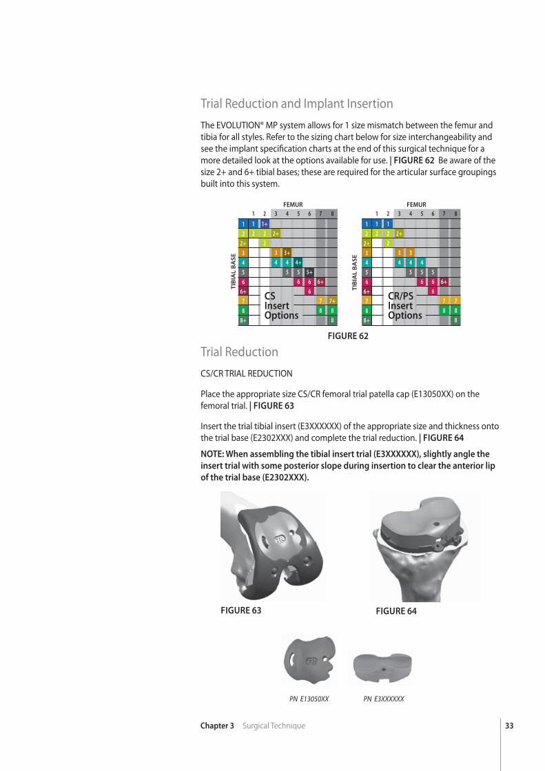
Trial Reduction and Implant InsertionThe EVOLUTION® MP system allows for 1 size mismatch between the femur and tibia for all styles. Refer to the sizing chart below for size interchangeability and see the implant specifi cation charts at the end of this surgical technique for a more detailed look at the options available for use. | FIGURE 62 Be aware of the size 2+ and 6+ tibial bases; these are required for the articular surface groupings built into this system.
Trial ReductionCS/CR TRIAL REDUCTION
Place the appropriate size CS/CR femoral trial patella cap (E13050XX) on the femoral trial. | FIGURE 63
Insert the trial tibial insert (E3XXXXXX) of the appropriate size and thickness onto the trial base (E2302XXX) and complete the trial reduction. | FIGURE 64
FIGURE 62
FIGURE 63 FIGURE 64
12
2+3456
6+78
8+
TIB
IAL
BA
SE
FEMUR
CR/PSInsertOptions
1 2 3 4 5 6 7 8
1 1 2 2 2+ 2 3 3 4 4 4 5 5 5 6 6 6+ 6 7 7 8 8 8
12
2+3456
6+78
8+
TIB
IAL
BA
SE
FEMUR
1 2 3 4 5 6 7 8
1 1+ 2 2 2+ 2 3 3+ 4 4 4+ 5 5 5+ 6 6 6+ 6 7 7+ 8 8 8
CSInsertOptions
PN E13050XX PN E3XXXXXX
NOTE: When assembling the tibial insert trial (E3XXXXXX), slightly angle the
insert trial with some posterior slope during insertion to clear the anterior lip
of the trial base (E2302XXX).
34 Chapter 3 Surgical Technique
FIGURE 66FIGURE 65
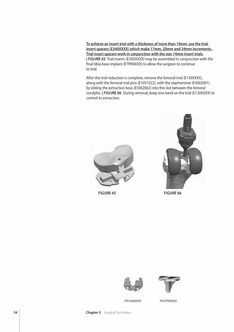
To achieve an insert trial with a thickness of more than 14mm, use the trial
insert spacers (E340XXXX) which make 17mm, 20mm and 24mm increments.
Trial insert spacers work in conjunction with the size 14mm insert trials. | FIGURE 65 Trial inserts (E3XXXXXX) may be assembled in conjunction with the fi nal tibia base implant (ETPKNXXX) to allow the surgeon to continueto trial.
After the trial reduction is complete, remove the femoral trial (E130XXXX), along with the femoral trial pins (E1051022), with the slaphammer (E5002001) by sliding the extraction boss (E5002002) into the slot between the femoral condyles. | FIGURE 66 During removal, keep one hand on the trial (E130XXXX) to control its extraction.
PN E340XXXX PN ETPKNXXX
35Chapter 3 Surgical Technique
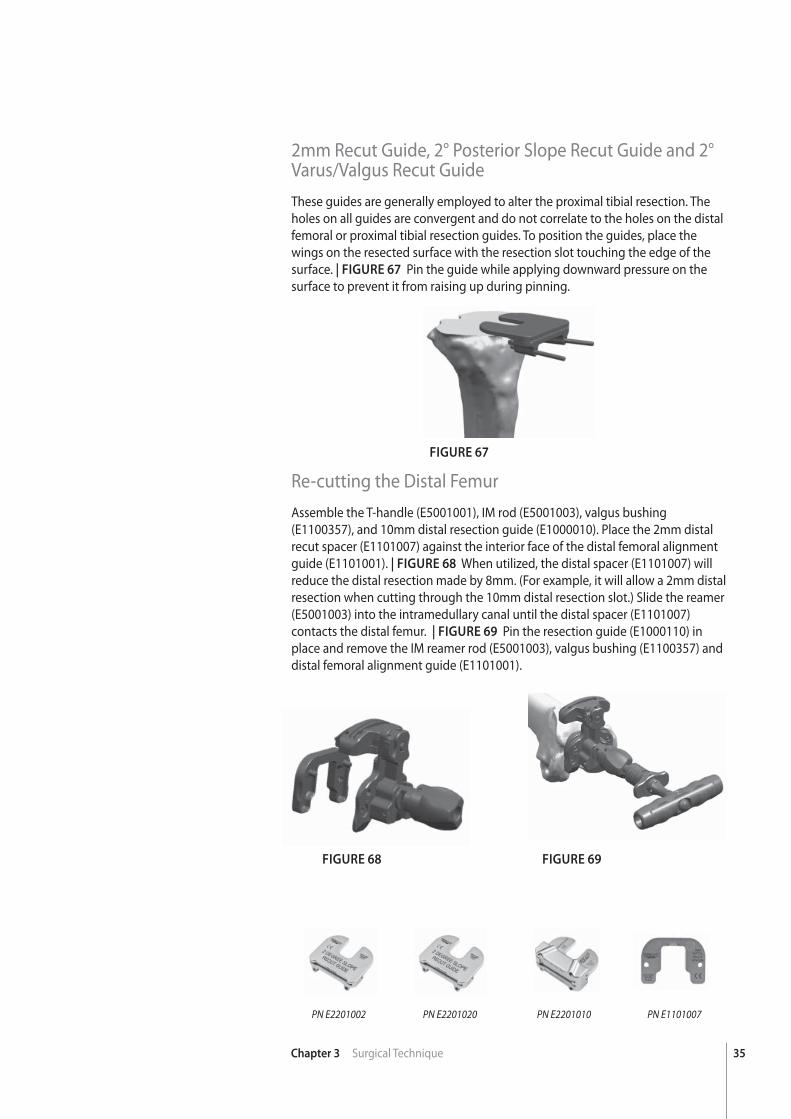
2mm Recut Guide, 2° Posterior Slope Recut Guide and 2° Varus/Valgus Recut GuideThese guides are generally employed to alter the proximal tibial resection. The holes on all guides are convergent and do not correlate to the holes on the distal femoral or proximal tibial resection guides. To position the guides, place the wings on the resected surface with the resection slot touching the edge of the surface. | FIGURE 67 Pin the guide while applying downward pressure on the surface to prevent it from raising up during pinning.
Re-cutting the Distal FemurAssemble the T-handle (E5001001), IM rod (E5001003), valgus bushing (E1100357), and 10mm distal resection guide (E1000010). Place the 2mm distal recut spacer (E1101007) against the interior face of the distal femoral alignment guide (E1101001). | FIGURE 68 When utilized, the distal spacer (E1101007) will reduce the distal resection made by 8mm. (For example, it will allow a 2mm distal resection when cutting through the 10mm distal resection slot.) Slide the reamer (E5001003) into the intramedullary canal until the distal spacer (E1101007) contacts the distal femur. | FIGURE 69 Pin the resection guide (E1000110) in place and remove the IM reamer rod (E5001003), valgus bushing (E1100357) and distal femoral alignment guide (E1101001).
FIGURE 67
FIGURE 68 FIGURE 69
PN E2201020 PN E2201010 PN E1101007PN E2201002
36 Chapter 3 Surgical Technique
Final Implant and Insert ImplantationThe recommended order for implantation is left to the discretion of the orthopaedic surgeon.
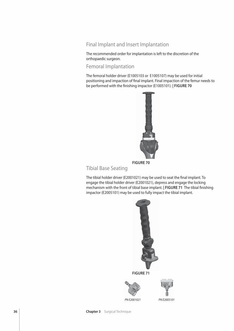
Femoral ImplantationThe femoral holder driver (E1005103 or E1005107) may be used for initial positioning and impaction of fi nal implant. Final impaction of the femur needs to be performed with the fi nishing impactor (E1005101). | FIGURE 70
Tibial Base SeatingThe tibial holder driver (E2001021) may be used to seat the fi nal implant. To engage the tibial holder driver (E2001021), depress and engage the locking mechanism with the front of tibial base implant. | FIGURE 71 The tibial fi nishing impactor (E2005101) may be used to fully impact the tibial implant.
FIGURE 70
FIGURE 71
PN E2001021 PN E2005101
37Chapter 3 Surgical Technique
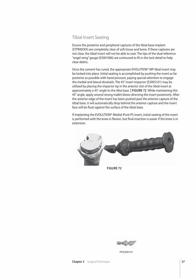
Tibial Insert SeatingEnsure the posterior and peripheral captures of the tibial base implant (ETPKNXXX) are completely clear of soft tissue and bone. If these captures are not clear, the tibial insert will not be able to seat. The tips of the dual reference “angel wing” gauge (E5001006) are contoured to fi t in the lock detail to helpclear debris.
Once the cement has cured, the appropriate EVOLUTION® MP tibial insert may be locked into place. Initial seating is accomplished by pushing the insert as far posterior as possible with hand pressure, paying special attention to engage the medial and lateral dovetails. The 45° insert impactor (E3005101) may be utilized by placing the impactor tip in the anterior slot of the tibial insert at approximately a 45° angle to the tibia base. | FIGURE 72 While maintaining this 45° angle, apply several strong mallet blows directing the insert posteriorly. After the anterior edge of the insert has been pushed past the anterior capture of the tibial base, it will automatically drop behind the anterior capture and the insert face will be fl ush against the surface of the tibial base.
If implanting the EVOLUTION® Medial-Pivot PS insert, initial seating of the insert is performed with the knee in fl exion, but fi nal insertion is easier if the knee is in extension.
FIGURE 72
PN E3005101

38 Chapter 3 Surgical Technique
Explant InformationFEMUR, TIBIA, AND PATELLA COMPONENTS
To remove the components, small osteotomes, power saws, or other surgical instruments may be used to disrupt the bone-cement interface. Care must be exhibited to save remaining bone stock as well as to prevent fracture. Once the components have been removed, rongeurs or small osteotomes as well as other surgical instruments may be used to remove the remaining cement.
INSERT REPLACEMENT
A narrow osteotome may be inserted into the anterior region of the insert to facilitate removal. A hemostat may be used to remove the insert once it is no longer locked to the tibial base. Care must be taken not to scratch or mar any component that is not intended to be removed.
39
chap
ter
Chapter 4 Addendum
4Addendum
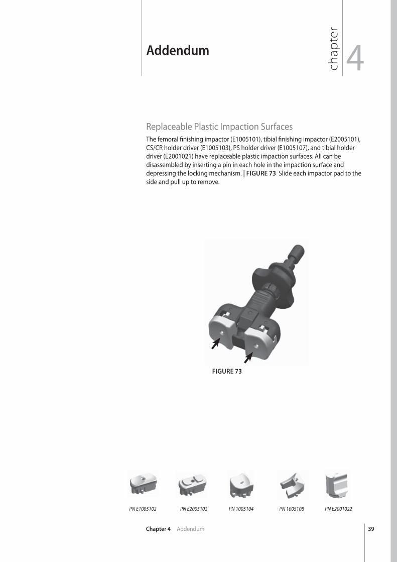
Replaceable Plastic Impaction SurfacesThe femoral fi nishing impactor (E1005101), tibial fi nishing impactor (E2005101), CS/CR holder driver (E1005103), PS holder driver (E1005107), and tibial holder driver (E2001021) have replaceable plastic impaction surfaces. All can be disassembled by inserting a pin in each hole in the impaction surface and depressing the locking mechanism. | FIGURE 73 Slide each impactor pad to the side and pull up to remove.
FIGURE 73
PN E2001022PN 1005108PN 1005104PN E2005102PN E1005102
40 Chapter 4 Addendum
FIGURE 74
ADVANCE® Patellar Reaming SystemThe ADVANCE® Patellar Reamer may be utilized for both recessed and onlay patellar implants.
SIZING THE PATELLA
To determine which patellar implant will be used, compare the patient’s patella with the patellar trials. This will help determine how much patellar bone should be removed to replicate patellar anatomy.
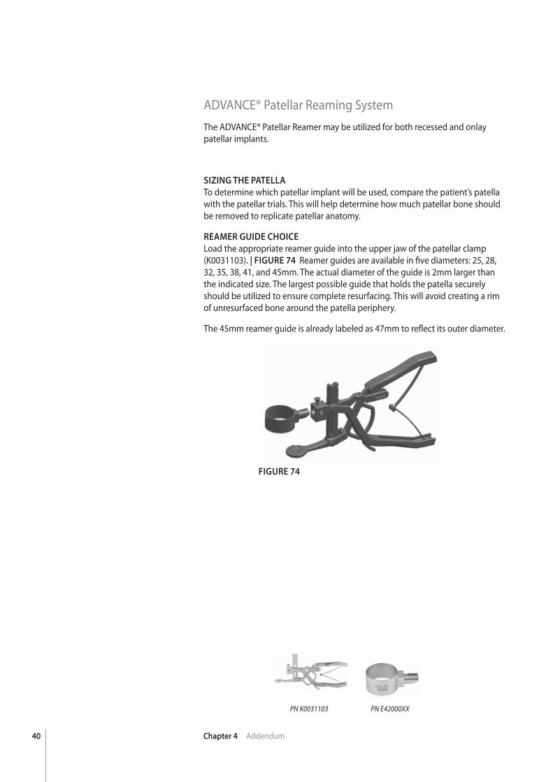
REAMER GUIDE CHOICE
Load the appropriate reamer guide into the upper jaw of the patellar clamp (K0031103). | FIGURE 74 Reamer guides are available in fi ve diameters: 25, 28, 32, 35, 38, 41, and 45mm. The actual diameter of the guide is 2mm larger than the indicated size. The largest possible guide that holds the patella securely should be utilized to ensure complete resurfacing. This will avoid creating a rim of unresurfaced bone around the patella periphery.
The 45mm reamer guide is already labeled as 47mm to refl ect its outer diameter.
PN E42000XXPN K0031103
41Chapter 4 Addendum
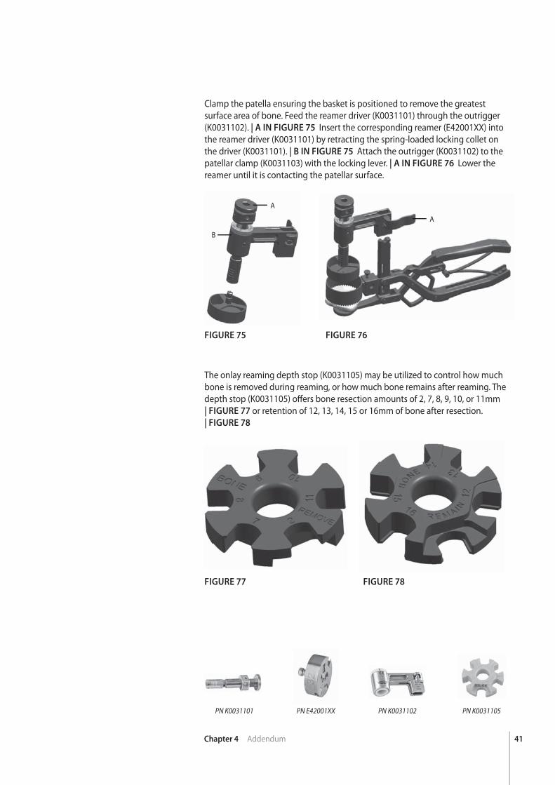
Clamp the patella ensuring the basket is positioned to remove the greatest surface area of bone. Feed the reamer driver (K0031101) through the outrigger (K0031102). | A IN FIGURE 75 Insert the corresponding reamer (E42001XX) into the reamer driver (K0031101) by retracting the spring-loaded locking collet on the driver (K0031101). | B IN FIGURE 75 Attach the outrigger (K0031102) to the patellar clamp (K0031103) with the locking lever. | A IN FIGURE 76 Lower the reamer until it is contacting the patellar surface.
FIGURE 75
FIGURE 77
FIGURE 76
FIGURE 78
The onlay reaming depth stop (K0031105) may be utilized to control how much bone is removed during reaming, or how much bone remains after reaming. The depth stop (K0031105) off ers bone resection amounts of 2, 7, 8, 9, 10, or 11mm| FIGURE 77 or retention of 12, 13, 14, 15 or 16mm of bone after resection.| FIGURE 78
A
B
A
PN K0031105PN K0031102PN K0031101 PN E42001XX
42 Chapter 4 Addendum
FIGURE 80
FIGURE 79
FIGURE 81
SETTING THE BONE RESECTION
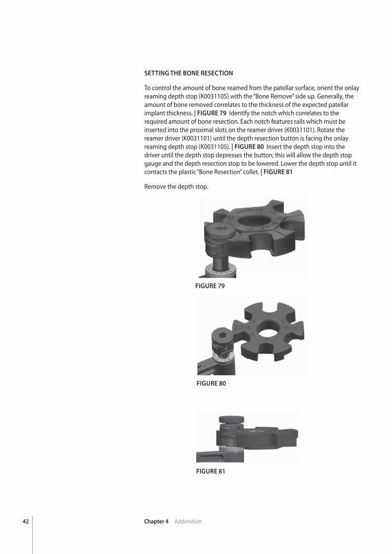
To control the amount of bone reamed from the patellar surface, orient the onlay reaming depth stop (K0031105) with the “Bone Remove” side up. Generally, the amount of bone removed correlates to the thickness of the expected patellar implant thickness. | FIGURE 79 Identify the notch which correlates to the required amount of bone resection. Each notch features rails which must be inserted into the proximal slots on the reamer driver (K0031101). Rotate the reamer driver (K0031101) until the depth resection button is facing the onlay reaming depth stop (K0031105). | FIGURE 80 Insert the depth stop into the driver until the depth stop depresses the button; this will allow the depth stop gauge and the depth resection stop to be lowered. Lower the depth stop until it contacts the plastic “Bone Resection” collet. | FIGURE 81
Remove the depth stop.
43Chapter 4 Addendum
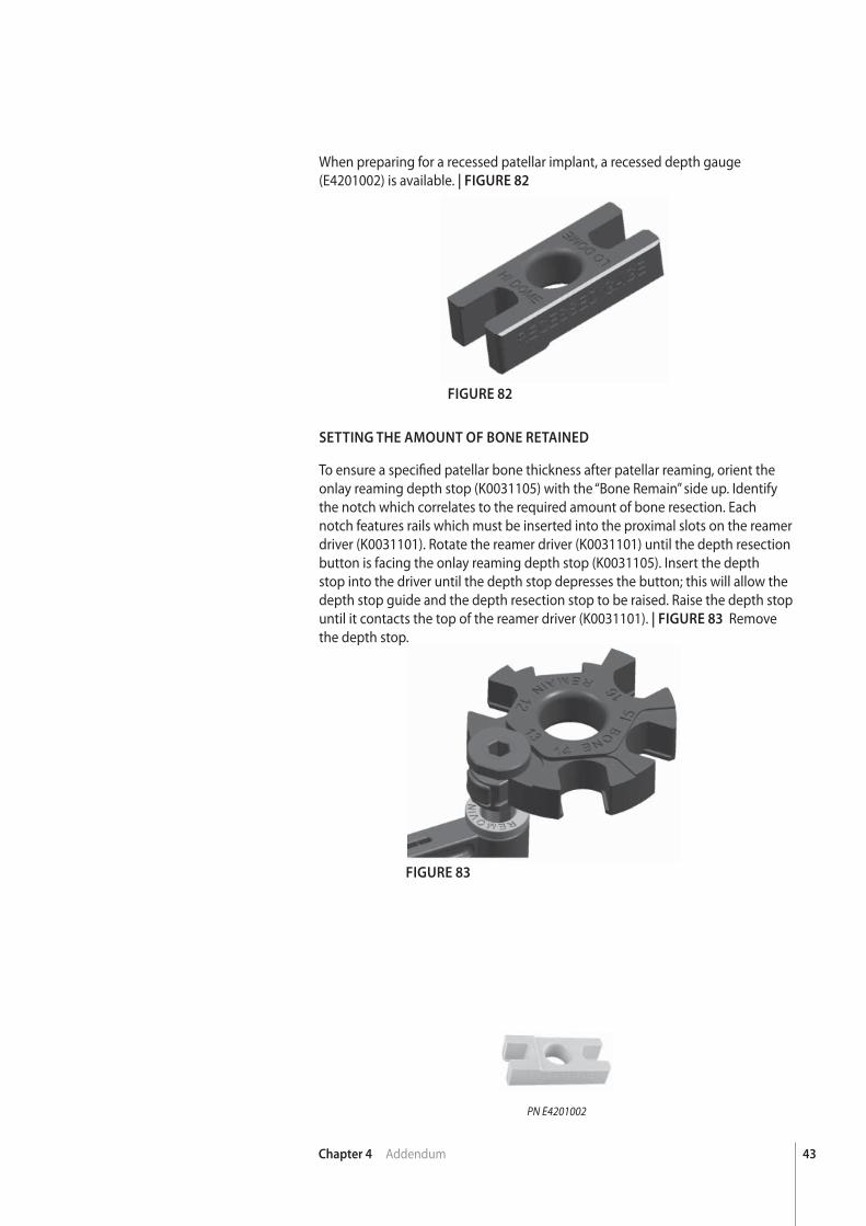
When preparing for a recessed patellar implant, a recessed depth gauge (E4201002) is available. | FIGURE 82
FIGURE 82
FIGURE 83
SETTING THE AMOUNT OF BONE RETAINED
To ensure a specifi ed patellar bone thickness after patellar reaming, orient the onlay reaming depth stop (K0031105) with the “Bone Remain” side up. Identify the notch which correlates to the required amount of bone resection. Each notch features rails which must be inserted into the proximal slots on the reamer driver (K0031101). Rotate the reamer driver (K0031101) until the depth resection button is facing the onlay reaming depth stop (K0031105). Insert the depth stop into the driver until the depth stop depresses the button; this will allow the depth stop guide and the depth resection stop to be raised. Raise the depth stop until it contacts the top of the reamer driver (K0031101). | FIGURE 83 Remove the depth stop.
PN E4201002
44 Chapter 4 Addendum
FIGURE 84
FIGURE 85
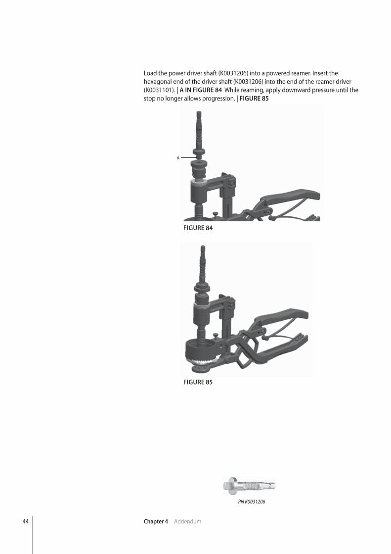
Load the power driver shaft (K0031206) into a powered reamer. Insert the hexagonal end of the driver shaft (K0031206) into the end of the reamer driver (K0031101). | A IN FIGURE 84 While reaming, apply downward pressure until the stop no longer allows progression. | FIGURE 85
A
PN K0031206
45Chapter 4 Addendum
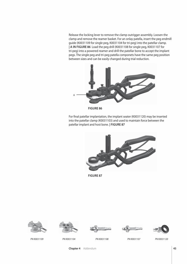
Release the locking lever to remove the clamp outrigger assembly. Loosen the clamp and remove the reamer basket. For an onlay patella, insert the peg endmill guide (K0031109 for single peg, K0031104 for tri-peg) into the patellar clamp.| A IN FIGURE 86 Load the peg drill (K0031108 for single peg, K0031107 for tri-peg) into a powered reamer and drill the patellar bone to accept the implant pegs. The single peg and tri-peg patella componets have the same peg position between sizes and can be easily changed during trial reduction.
FIGURE 86
FIGURE 87
For fi nal patellar implantation, the implant seater (K0031120) may be inserted into the patellar clamp (K0031103) and used to maintain force between the patellar implant and host bone. | FIGURE 87
PN K0031107PN K0031108PN K0031104PN K0031109 PN K0031120
A
chap
ter
46
5
Chapter 5 Instrument Kit Information
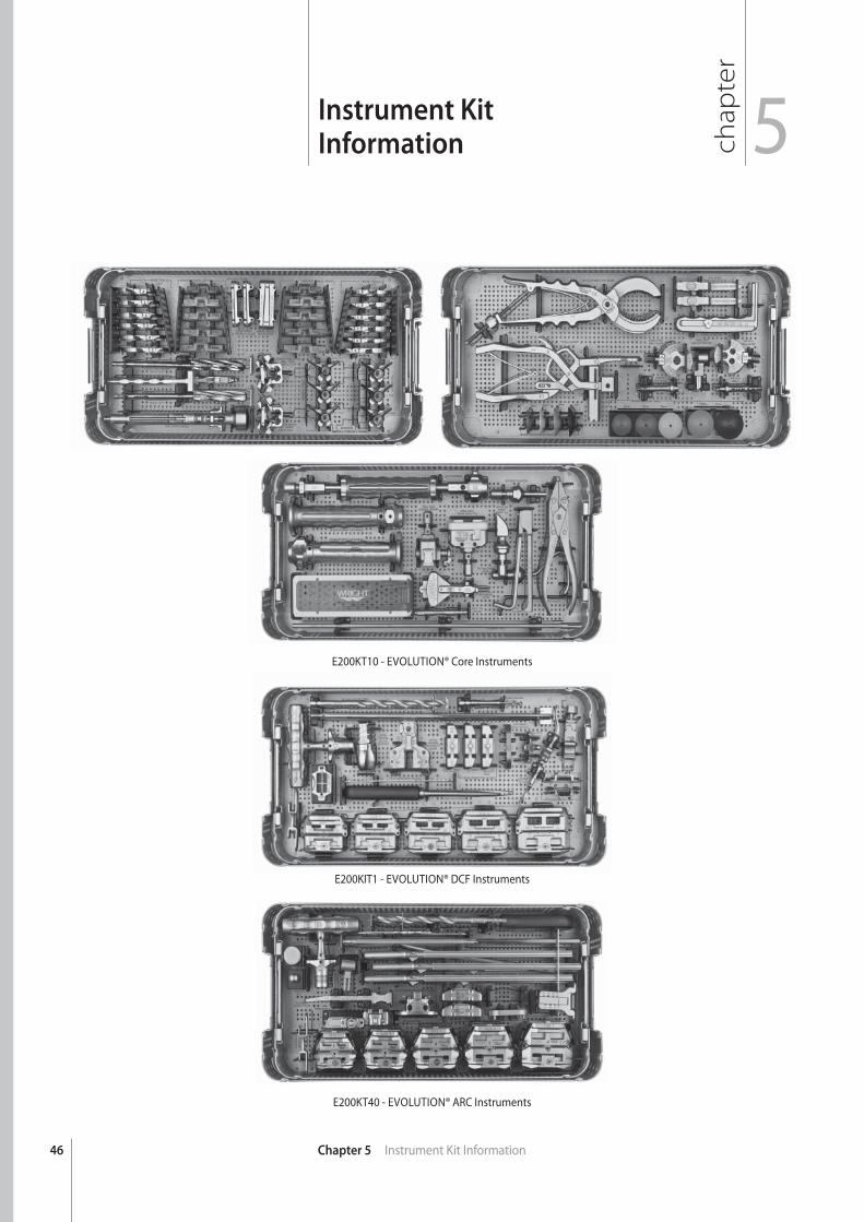
Instrument KitInformation
E200KT10 - EVOLUTION® Core Instruments
E200KIT1 - EVOLUTION® DCF Instruments
E200KT40 - EVOLUTION® ARC Instruments
47Chapter 5 Instrument Kit Information
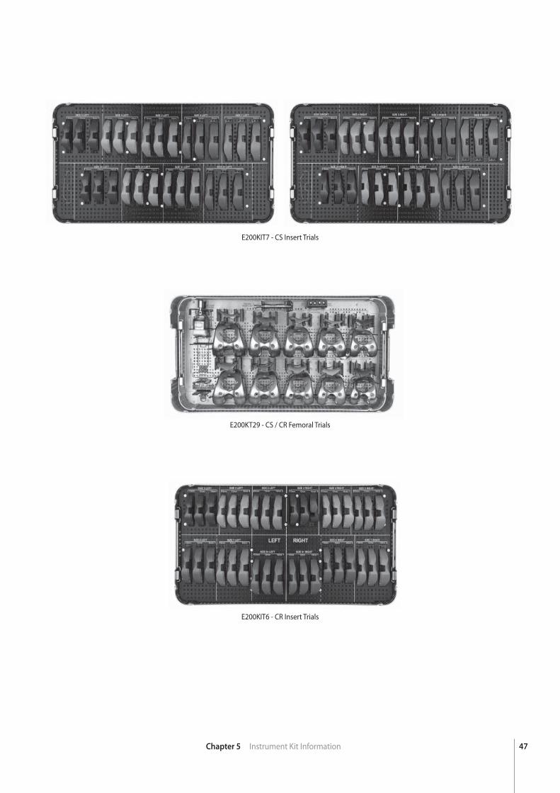
E200KIT7 - CS Insert Trials
E200KT29 - CS / CR Femoral Trials
E200KIT6 - CR Insert Trials
48 Chapter 5 Instrument Kit Information
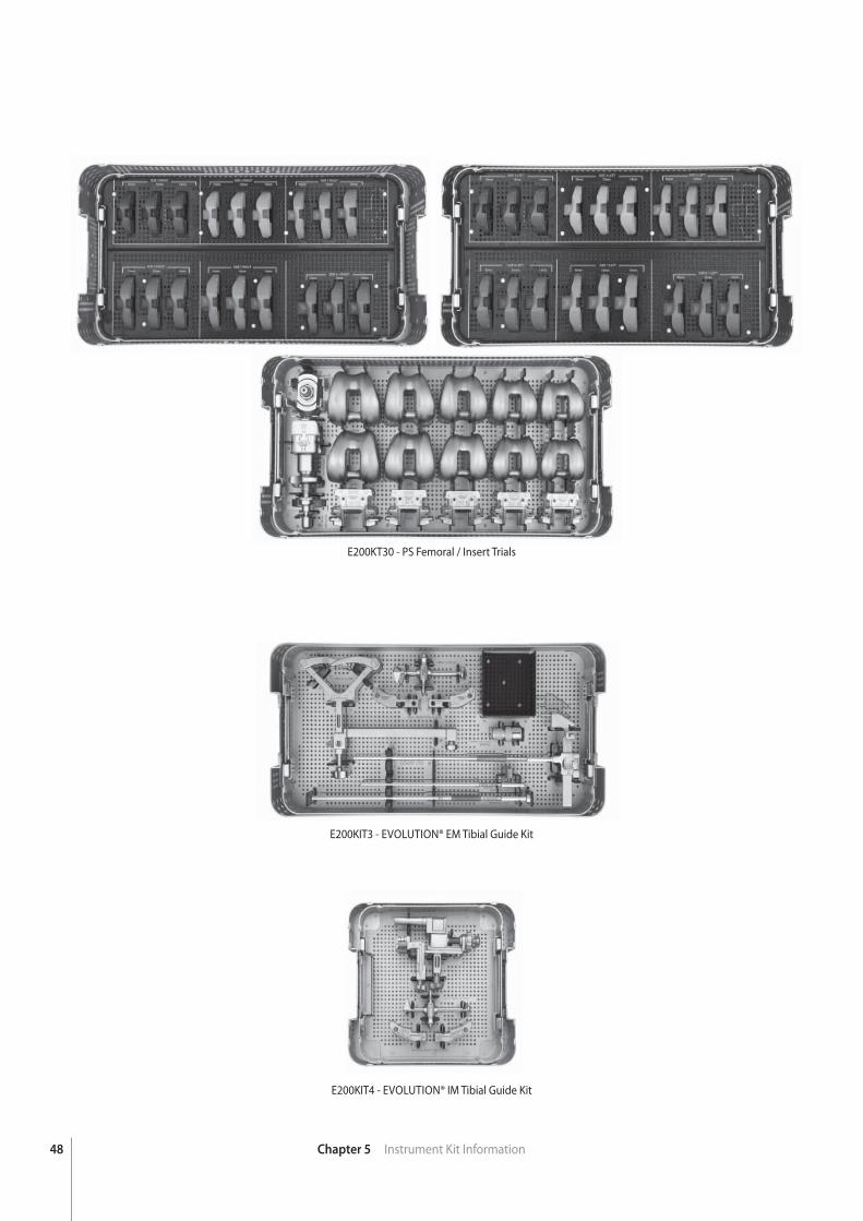
E200KT30 - PS Femoral / Insert Trials
E200KIT3 - EVOLUTION® EM Tibial Guide Kit
E200KIT4 - EVOLUTION® IM Tibial Guide Kit
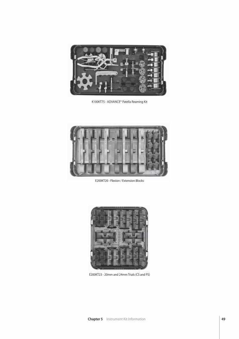
49Chapter 5 Instrument Kit Information
K100KT75 - ADVANCE® Patella Reaming Kit
E200KT20 - Flexion / Extension Blocks
E200KT23 - 20mm and 24mm Trials (CS and PS)
chap
ter
50
ImplantDimensions
Chapter 6 Implant Dimensions
6
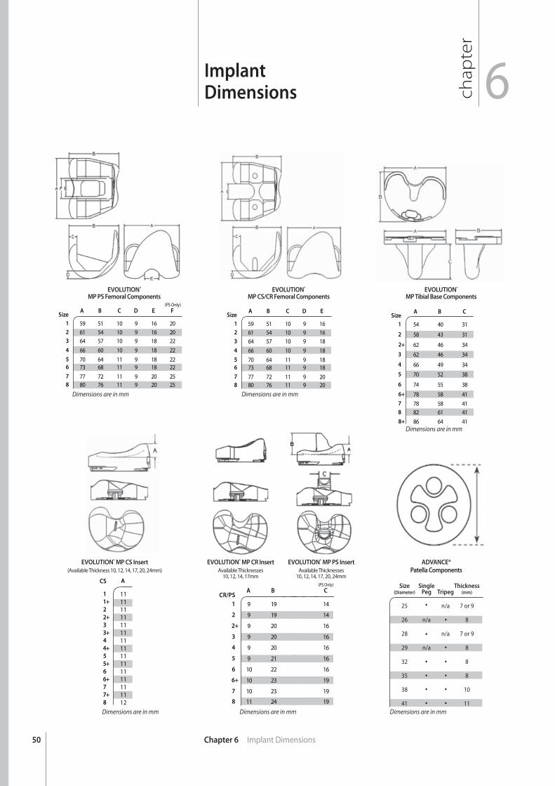
SizeA B C D E F
(PS Only)
1 59 51 10 9 16 202 61 54 10 9 16 203 64 57 10 9 18 22
4 66 60 10 9 18 22
5 70 64 11 9 18 226 73 68 11 9 18 22
7 77 72 11 9 20 258 80 76 11 9 20 25
SizeA B C D E
1 59 51 10 9 162 61 54 10 9 163 64 57 10 9 18
4 66 60 10 9 18
5 70 64 11 9 186 73 68 11 9 18
7 77 72 11 9 208 80 76 11 9 20
SizeA B C
1 54 40 31
2 58 43 31
2+ 62 46 34
3 62 46 34
4 66 49 34
5 70 52 38
6 74 55 38
6+ 78 58 41
7 78 58 418 82 61 41
8+ 86 64 41
CS A
1 111+ 112 112+ 113 113+ 114 114+ 115 115+ 116 116+ 117 117+ 118 12
CR/PSA B
1 9 19
2 9 19
2+ 9 20
3 9 20
4 9 20
5 9 21
6 10 22
6+ 10 23
7 10 23
8 11 24
Size Single Thickness (Diameter) Peg Tripeg (mm)
25 n/a 7 or 9
26 n/a 8
28 n/a 7 or 9
29 n/a 8
32 8
35 8
38 10
41 11
C (PS Only)
14
14
16
16
16
16
16
19
19
19
EVOLUTION®
MP PS Femoral ComponentsEVOLUTION®
MP CS/CR Femoral ComponentsEVOLUTION®
MP Tibial Base Components
ADVANCE®
Patella Components
EVOLUTION® MP CS Insert
(Available Thickness 10, 12, 14, 17, 20, 24mm)EVOLUTION® MP PS Insert
Available Thicknesses10, 12, 14, 17, 20, 24mm
EVOLUTION® MP CR Insert
Available Thicknesses10, 12, 14, 17mm
Dimensions are in mm Dimensions are in mm
Dimensions are in mm
Dimensions are in mmDimensions are in mm Dimensions are in mm

51

™Trademarks and ®Registered marks of Wright Medical Technology, Inc. ©2011 Wright Medical Technology, Inc. All Rights Reserved. MK539-1109 R911
Wright Medical Technology, Inc.
5677 Airline RoadArlington, TN USA 38002901.867.9971800.238.7188www.wmt.com
Wright Medical EMEA
Hoogoorddreef 51101 BA AmsterdamThe Netherlands011.31.20.545.0100www.wmt-emea.com


![Surgical debulking, lymphatico venous anastomosis ... surgery is performed in two stages both over the medial and laterals aspect of the limbs[67]. Usually the medial aspect of the](https://img.pdfslide.us/doc/110x75/5ed53f5fcdc7ed4257448f06/surgical-debulking-lymphatico-venous-anastomosis-surgery-is-performed-in-two.jpg)