Embed Size (px)
Citation preview
MECHANISMS OF HIGH TEMPERATURE CREEP OF NICKEL-BASE SUPERALLOYS
UNDER LOW APPLIED STRESS
Alexander Epishin1 and Thomas Link2
1Federal Institute for Materials Research and Testing, Unter den Eichen 87, 12205 Berlin, Germany2Technical University Berlin, Institute for Material Science and Engineering, BH 18,
Ernst Reuter Platz 1, 10587 Berlin, Germany
Keywords: Superalloys, Creep, Porosity, Dislocations, Diffusion
Abstract
[001] single-crystal (SC) specimens of the superalloys CMSX-4
and CMSX-10 were tested for creep at 1100°C under tensile
stresses between 105 and 135 MPa. For these testing conditions
superalloys show creep curves with the classical shape: primary
creep is followed by a long period with low, nearly constant creep
rate. It was found that porosity significantly increases during this
steady creep. The central point of the investigation was to
understand the deformation mechanism of steady creep and its
connection with porosity growth. Specimens deformed up to
certain strain levels were analyzed by density measurements,
scanning electron microscopy (SEM) and transmission electron
microscopy (TEM) which supplied information about porosity
growth, evolution of the ’ microstructure as well as the
mobility and reactions of dislocations during the creep process.
It was found that the non-conservative movement (glide/climb) of
the a/2<011> dislocations deposited in the ’ interface during
primary creep produces most of the plastic strain during the
following steady creep. Interfacial climb creates vacancies, which
diffuse either to pores increasing porosity or to interfacial a<100>
edge dislocations, assisting their climb through the ’ phase.
Under the testing conditions applied the recovery mechanism is ’
climb, which has the following two effects: it reduces the
constraining of the plastically deformed phase by the elastically
deformed ’ phase, thus allowing further dislocation glide in the
matrix channels and it decreases the osmotic force, which
suppresses interfacial glide/climb. Creep deformation accelerates
when the ’ microstructure coarsens and the ’ rafts form
junctions, enabling a higher mobility of the ’ dislocations.
Introduction
Improvement of the efficiency of gas turbine engines requires to
increase the gas temperature and consequently the operating
temperature of the turbine blades. Rhenium containing SC
superalloys like CMSX-4 and CMSX-10 allow a long-term
operation of the blade material at temperatures up to about
1100°C [1, 2]. These temperatures are comparatively new and
therefore only few investigations on creep mechanisms exist for
this temperature range, whereas they are quite frequent for
temperatures below 1000°C (for an overview see [3]).
In the present work [001] SCs of the superalloys CMSX-4 and
CMSX-10 were tested for creep at 1100°C and 105-135 MPa. For
tests at lower temperatures and higher stresses the creep curve has
a sigmoidal or exponential shape but in our case superalloys show
the classical creep behavior, i.e. pronounced steady creep as
observed by several authors [4-6]. During steady creep the
material retains the rafted ’ microstructure [4, 7] and porosity
grows [8, 9]. Under high stresses, where the ’ phase can be
sheared by couples of a/2<011> dislocations, the classical
mechanism of high temperature ’ cutting [10], rafting reduces the
lifetime [11]. But under low stresses, insufficient to press
a/2<011> dislocations into the ’ superlattice, it improves the
creep resistance by retarding the matrix dislocations [4-6]. This is
the case in the presented paper. In spite of this retarding effect the
plastic deformation continues after primary creep, however the
rafted structure deforms with low steady strain rate. The aim of
the present investigation was to understand the mechanisms of
this steady creep and its connection with porosity growth. This
knowledge is intended to use for modeling the creep behavior of
superalloys at high temperatures on a microstructural base [12].
Materials and Methods
The investigated nickel-base single-crystal superalloys of the
second and third generation CMSX-4 and CMSX-10 contain
about 3 and 6 wt% rhenium respectively. [001] SC specimens of
these superalloys were produced by Doncasters Precision Casting,
Bochum, Germany. The specimens were tested for creep at a
temperature of 1100°C and tensile stresses between 105 and 135
MPa. At first rupture tests were performed to obtain the total
creep curves, while further tests were interrupted at characteristic
points of the creep curves. The creep induced porosity was
determined by density measurement, allowing an accuracy better
than / = 3 10-4 [9].
The coarsening of the / ’ structure was analyzed by SEM in the
secondary dendrite arms representing most of the material.
Because the rafted structure is rather regular it allows to apply
Fourier analysis for image processing, supplying the structure
period , the sum of precipitate and channel width along the stress
axis [7]. TEM investigations of specimens from the different
creep stages allowed to determine the deformation mechanisms
being active during creep.
Results
At high temperatures and low stresses, superalloys show steady
creep, the clearer the lower the stresses. To quantify the duration
of steady creep, shown in Figure 1, the relative deviation from the
minimum creep rate minmin%100 is plotted as a
function of time/lifetime % for CMSX-4 at 1100°C. Defining
“steady creep” as a deformation with less than 20%, steady
creep lasts under 135 MPa 1/3 of the lifetime, under 105 MPa 2/3.
137
Superalloys 2004Edited by K.A. Green, T.M. Pollock, H. Harada,
TMS (The Minerals, Metals & Materials Society), 2004T.E. Howson, R.C. Reed, J.J. Schirra, and S, Walston

Time/Lifetime, %
0 20 40 60 80 100
Cre
ep
str
ain
,%
0,0
0,2
0,4
0,6
0,8
1,0
1,2
1,4
117MPa
135MPa
105MPa
CMSX-41100 °C
Time/Lifetime, %
0 20 40 60 80 100
Dev
iati
on
fro
m m
inim
um
cre
ep
ra
te,
%
0
10
20
30
40
50
105
MP
a
117
MP
a
135
MP
a
33% 51%
66%
Figure 1. At 1100°C in CMSX-4 primary creep is followed by a region of nearly constant creep rate. This
steady creep is the longer the lower the stress. ( Lifetimes: For 135 MPa 149h, for 117 MPa 227h, for 105 MP
692h. For the 105 MPa specimen rupture necking occurred outside the extensometer.)
Metallographic analysis shows a significant increase in porosity
during creep at 1100°C, 120 MPa. Visual comparison of Figure
2a, 0 h and Figure 2b, 654 h, gives a qualitative impression of
porosity growth in CMSX-10. The pores in Figure 2a, round and
positioned in the interdendritic region, are typical for a heat
treated, undeformed material.
A detailed inspection of a single pore confirms, that its surfaces
is really round (Figure 2c). This becomes remarkable in
comparison with crept specimens. Looking there at the pores
(Figure. 2b) one still finds big round pores but additionally small
pores, which are now randomly distributed over the whole cross
section. Higher magnification reveals their quite perfect
crystallographic shape (Figure 2d) with surfaces of {001} type
or in other cases {011} type. All three features: crystallographic
shape, small size and equal distribution are indications for their
generation during creep. Searching for the nucleation sites of
these creep induced pores one finds in the same specimen at the
/ ’ interface on the ’ side pores below 1 m size. (Figure 2e).
Figure 2. Porosity in CMSX-10, cross-sections, SEM.
Undeformed material after heat treatment, porosity 0.3 area % (a). Deformed material,
654h, 1100°C, 120MPa, far from the rupture surface, porosity 1.5 area % (b).
138

Steady creep strainst
, %
0,0 0,2 0,4 0,6 0,8 1,0 1,2 1,4
D-p
oro
sity
VD =
-,
%
0,0
0,2
0,4
0,6
0,8
1,0
1,2
1,4
CMSX-4
CMSX-10
25 h150 h
292 h
393 h, 117 MPa
149 h, 135 MPa
692 h, 105 MPa
550 h
330 h
60 h
200 h
V D=st
Figure 2. Porosity in CMSX-10, cross-sections, SEM.
Round pore in undeformed material. Diameter about 15 m (c).
Pore with crystallographic shape. Same specimen as in figure b.
Size about 10 m (d). Pores at the / ’ interface (arrows) in the
same specimen as in figure b. Size less than 1 m (e).
To analyze the connection between steady creep and porosity
growth, first the density at the end of primary creep (tp) was
determined (tp= 25 h for CMSX-4 and 60 h for CMSX-10). Then
the relative decrease of the density / was measured, which is
equal to the deformation induced porosity VD having developed
during further creep: VD / . The steady creep strain st was
calculated as the additional strain after primary creep using the
minimum creep rate min : st = min (t tp). This linear
Figure3. Steady creep strain at 1100°C is connected with the
increase of porosity. Black dots: CMSX-4, white dots: CMSX-
10. The dots without given stress level correspond to 120 MPa
increase st was compared with the growth of porosity.
Figure 3 shows the results obtained for CMSX-4 and CMSX-10.
If the creep mechanism, leading to the growth of porosity, is the
only mechanism, which is active during steady creep, the
experimental points should lie on the dashed line. Indeed the
measuring points come close to this line. The strongest deviation
was found for the specimen with the highest stress of 135 MPa,
indicating that at higher stresses different creep mechanisms are
activated, which are dominant for the strain.
139

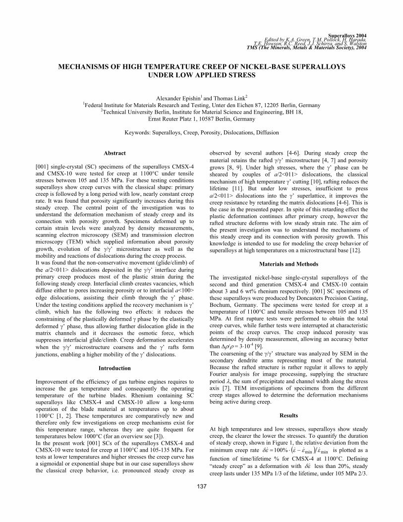
Fig. 4 shows the coarsening kinetics of the ’ microstructure
during creep at 1100°C, for CMSX-4 at 117 MPa and for
CMSX-10 at 120 MPa. The points marked as “Rafted”
correspond to specimens where complete ’ rafting
perpendicular to the load axis first was found. The horizontal
arrows mark the steady creep interval tst determined by the <
20% criterion. The graph shows that the beginning of steady
creep coincides with the end of rafting, which is in agreement
with [4-6], where rafting is reported to have a strengthening
effect in case of low applied stresses.
Time, h
0 100 200 300 400 500 600
Str
uctu
re p
erio
d,
m
0,0
0,2
0,4
0,6
0,8
1,0
1,2
1,4
1,6
1,8
CMSX-4, 117 MPa
CMSX-10, 120 MPa
tst
= 90 h
tst
= 215 hRupture
Rafted
Figure 4. Coarsening of the ’ microstructure during creep at
1100°C, measured in the secondary dendrite arm
It follows from the graph that creep accelerates when the rafted
’ microstructure coarsens up to =15-25%. This increase
in size is accompanied by a morphology change called
“topological inversion” [13]: is now embedded in ’. It should
be mentioned that the coarsening rate d /dt in CMSX-10 is
nearly three times higher than in CMSX-4 (d /dt=23 10 4 m/h
and 8 10 4 m/h), which causes a similar reduction of tst (90 h
versus 215 h). The reason for the faster coarsening of CMSX-10
is probably the smaller aspect ratio of the rafts (raft length/raft
thickness). This could be caused by the less regular alignment of
the ’ cuboids in undeformed CMSX-10 due to the lower
absolute value of the ’-misfit.
TEM analysis of interfacial dislocations in CMSX-4 and
CMSX-10 specimens confirmed earlier findings [13], that
deformation starts with the expansion of a/2<101> dislocations
gliding through the matrix channels and leaving behind 60°
dislocations in the interfaces. (A bold index means, that its
position is fixed. The stress direction is [001]) Plastic
deformation produced by this glide takes place only in the
matrix. The ’ phase adapts to the strain elastically and becomes
thus the source for induced back stresses: the harder ’ phase
constrains the softer phase. The interfacial dislocations move
along the (001) interface and form regular networks, a process
accompanied with the formation of a/2<110> segments, i.e. with
Burgers vectors lying in the interface. The interfacial movement
is a glide/climb process producing plastic strain which under
tensile stress contributes to the specimen elongation. Because
interfacial climb absorbs atoms for the growth of the half
extraplanes, it simultaneously generates vacancies at the
interfaces which condense either in existing pores or
conglomerate into new pores. Thus the growth of porosity
during creep is an indication of active interfacial movement. The
increasing vacancy concentration results in an osmotic force
suppressing the movement of the interfacial dislocations. So
both, the back stress and the osmotic force are hindering further
deformation.
ba
Figure 5. Interfacial dislocations in CMSX-10 after 200 h creep at 1100°C, 120 MPa, transition from steady to accelerated creep.
Dislocation reactions lead to segments with a<100> Burgers vectors. Horizontal segment (black arrow): a[010], vertical (white arrow,
dislocation out of contrast): a[100]. Incident beam direction: [001] (a). Network segments are bowed out in several parts of the network (b).
0.2 m
200
02050nm
140
Analysis of interfacial dislocation networks in the 200 h
specimen gave that reactions between a/2<110> dislocations
now lead to segments with a<100> Burgers vectors (Figure 5a).
Figure 5b shows, how the network looks in CMSX-10 after 200
h creep at 1100°C, 120 MPa. The meshes of the networks have
bowed out, indicating a shift of the network in the interface
possibly due to reduction of the osmotic force.
Further investigations revealed, that the a<100> interfacial
dislocations are the source for a recovery mechanism, which
allows creep to continue. Figure 6a shows a section through a ’
raft in CMSX-4 in the middle of steady creep. The / ’
interfaces are densely covered with dislocations, some of which
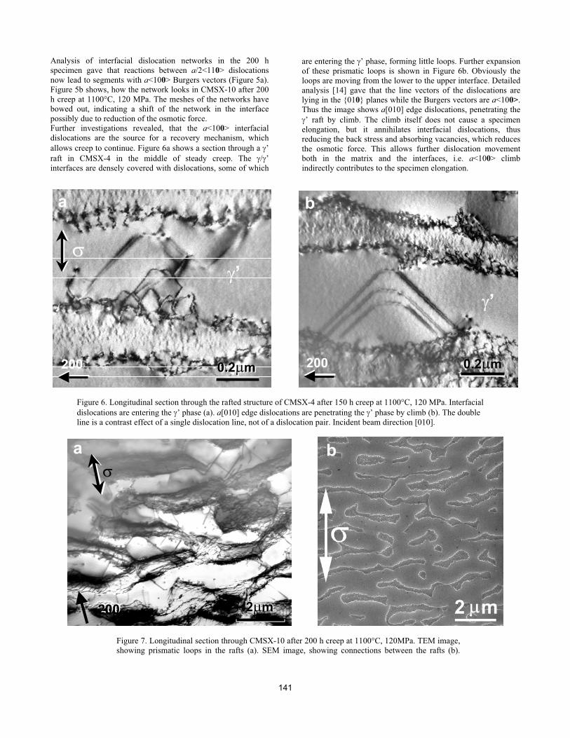
are entering the ’ phase, forming little loops. Further expansion
of these prismatic loops is shown in Figure 6b. Obviously the
loops are moving from the lower to the upper interface. Detailed
analysis [14] gave that the line vectors of the dislocations are
lying in the {010} planes while the Burgers vectors are a<100>.
Thus the image shows a[010] edge dislocations, penetrating the
’ raft by climb. The climb itself does not cause a specimen
elongation, but it annihilates interfacial dislocations, thus
reducing the back stress and absorbing vacancies, which reduces
the osmotic force. This allows further dislocation movement
both in the matrix and the interfaces, i.e. a<100> climb
indirectly contributes to the specimen elongation.
a b
’
’
0.2 m200200 0.2 m0.2 m
Figure 6. Longitudinal section through the rafted structure of CMSX-4 after 150 h creep at 1100°C, 120 MPa. Interfacial
dislocations are entering the ’ phase (a). a[010] edge dislocations are penetrating the ’ phase by climb (b). The double
line is a contrast effect of a single dislocation line, not of a dislocation pair. Incident beam direction [010].
a b
200200 2 m2 m
Figure 7. Longitudinal section through CMSX-10 after 200 h creep at 1100°C, 120MPa. TEM image,
showing prismatic loops in the rafts (a). SEM image, showing connections between the rafts (b).
141

A TEM overview in CMSX-10 after 200 h creep at 1100°C, 120
MPa shows, that such prismatic loops are frequent during the
transition from steady to accelerated creep (Figure 7a). A SEM
image of the same specimen (Figure 7b) shows that the rafts are
now connected while the matrix channels are interrupted, which
can be quantified in terms of topological inversion [13, 15]. The
’ phase, now playing the role of the matrix, provides channels
for the expansion of the ’ dislocations throughout the material.
Therefore the strain rate increases and the creep process enters
into the accelerated stage.
Discussion
The main question in this investigation of the creep of
superalloys at high temperature and low stresses is: how does
creep continue when rafts have formed and the dislocation
movement in the matrix channels is blocked by back stresses?
Usual answers are: the rafts have to be cut or the dislocations
have to climb around. But when the stresses are too low for ’
cutting and the ’ cubes have fused into extended plates, both
explanations fail.
The experimental fact, that steady creep strain and porosity
increase are connected is an indication for a new mechanism.
The central point for the explanation of porosity is, that
dislocation movement (glide/climb) in the rafted ’
microstructure is possible in the / ’ interfaces, i.e.
perpendicular to the stress axis. The specimen length increases
because the half extraplanes inserted perpendicular to the stress
direction grow. The result of the climb component of this
movement are the vacancies, which manifests by the porosity
growth observed. The next experimental observation are the
interfacial a<100> dislocations, entering and penetrating the ’
phase under osmotic and misfit forces. These dislocations are
additionally acting as vacancy sinks, because their extraplanes
are shrinking. Figure 8 shows the connection between interfacial
glide/climb, porosity growth and ’ climb. It should be
mentioned that the ’ climb observed differs from a complex ’
movement of a<100> dislocations under shear creep loading
observed in [16]. The movement there was interpreted as ’
cutting, i.e. as a combination of zigzag displacements resulting
in a macroscopic movement along {110} or {111} glide planes.
The classical mechanism of ’ deformation during the
accelerated stage of high temperature creep is shearing by pairs
of a/2<101> dislocation [10]. So this is certainly the first idea
for interpreting Figure 6. The correct solution however follows
from the TEM analysis of Burgers and line vectors: the
dislocations are a<100> prismatic loops climbing through the ’
phase.
A consequence of the relaxation mechanism described above is,
that glide of a/2<101> dislocation loops in the matrix channels,
blocked before by back stresses becomes possible again. The
question is: how much of the stationary creep strain is based on
interfacial glide/climb and how much on this additional matrix
loops? The ratio R between these two strain contributions can be
quantified using the experimental value ([001] creep
strain)/(increase in pore volume fraction) as described in detail
in [17]. This consideration allows to estimate, that in CMSX-4
and CMSX-10 at 1100°C and stresses of 105-120 MPa about
85% of the secondary creep strain are caused by interfacial
dislocation movement.
Figure 8. Connection between dislocation movement, vacancies
and pores. The interfacial glide/climb, shown by a tilted
dislocation in the / ’ interface, produces vacancies (white
circles). They diffuse along the interface and low angle
boundaries and condense in pores or they support the climb of
a<100> dislocations through the ’-phase. (big circle: enlarged
/ ’ interface)
Conclusions
At high temperatures and low stresses primary creep of
superalloys is followed by a long creep period with low, nearly
constant strain rate. The deformation mechanism being active in
the completely rafted / ’ structure is mainly transverse
climb/glide of a/2<101> interfacial dislocations.
Macroscopically this climb results in a specimen elongation,
microscopically in the generation of vacancies and dislocation
segments with a<100> Burgers vectors. The vacancies either
condense forming pores or allow the interfacial a<100>
segments to climb as prismatic loops through the rafts.
Vacancy annihilation and climb through the rafts are both
relaxation mechanisms, allowing additional a/2<101> glide in
the matrix channels.
Creep accelerates when the / ’ structure topologically inverts,
giving way for a<100> dislocations to spread over the simply
connected ’ phase.
Acknowledgement
The authors wish to thank the Deutsche Forschungsgemeinschaft
for financial support (Project PO 405/7-1, RE 688/41-1).
References
1. D.J. Frazier, J.R. Whetstone, K. Harris, G.L. Erickson,
R.E. Schwer, „Process and Alloy Optimization for CMSX-4
Superalloy Single crystal Airfoils”, in: E. Bachelet et al. (Eds.),
High Temperature Materials for Power Engineering 1990, D.
Reichel, Dordrecht, (1990), 1281-1300.
142

2. G.L. Erikson, “The Development and Application of
CMSX-10,” Superalloys 1996, Edited by R.Kissinger, D.J.
Deye, SD.L. Anton, A.D. Cetel, M.V. Nathal, T.M. Pollock and
D.A. Woodford, TMS, (1996), 35-44.
3. T.M. Pollock and R.D. Field, “Dislocations and High
Temperature Plastic Deformation of Superalloy Single
Crystals,” Dislocations in Solids, Vol. 11., F. R. N. Nabarro and
M.S. Duesbery, editors, Elsevier, Amsterdam, (2002).
4. R.A. MacKay and L. J Ebert, “Development of - ’
Lamellar Structures in a Nickel-Base Superalloy during Elevated
Temperature Mechanical Testing,” Metall. Trans. A, 16A
(1985), 1969-1982.
5. W. Schneider, “High Temperature Creep Behavior and
Microstructure of the Single Crystal Superalloy CMSX-4 at
Temperatures from 800°C up to 1100°C,” (PhD thesis,
Erlangen-Nürnberg University, Germany, 1993), 65-69.
6. R.C. Reed, N. Matan, D.C. Cox, M.A. Rist and C.M.F
Rae,”Creep of CMSX-4 Superalloy Single Crystals: Effect of
Rafting at high Temperature,” Acta mater., 47, (1999), 3367-
3381.
7. A. Epishin et al. “Evolution of the / ’ microstructure
during high temperature creep of a nickel base superalloy,” Acta
mater., 48, (2000) 4169-4177
8. J. Komenda and P.J. Henderson, “Growth of pores
during the creep of a single crystal nickel-base superalloy,”
Scripta mater. 37 (1997), 1821-1826.
9. A. Epishin et al., “Investigation of Porosity in Single-
Crystal Nickel-Base Superalloys,” Proceedings of the 7th
Conference on Materials for Advanced Power Engineering,
Liege, 2002), 217-226
10. B.H. Kear and J.M. Oblak, “Deformation Modes in ’
Precipitation Hardened Nickel-Base Alloys,” Journal de
Physique, (1974), C7-35-45
11. H. Mughrabi “ / ’ Rafting and its Effect on the Creep
and Fatigue Behaviour of Monocrystalline Superalloys”, The
Johannes Weertman Symposium, ed. R.J. Arsenault et al.: (The
Minerals, Metals & Materials Society, 1996), 267-278.
12. B. Fedelich, “A microstructure based constitutive
model for the mechanical behavior at high temperature of
nickel-base single crystal superalloys” Computational. Materials
Science, 16, (1999), 248-258.
13. A. Fredholm and J.L. Strudel, “High-Temperature
Creep Mechanisms in Single Crystals of some High
Performance Nickel-Base Superalloys” (High Temperature
Alloys, Their Expoitable Potential, Proc. of Petten. Int. Conf.
1985, ed. J.B. Mariott et al., Elsevier Applied Science, London,
1987), 9-18
14. M. Klaus, “Development of the dislocation Structure
in CMSX-10 during High Temperature Creep” (Diploma thesis,
Technical University Berlin, Germany, 2003), 44-50
15. A. Epishin et al., “Kinetics of the topological
Inversion of the / ’ Microstructure during Creep of a Nickel-
based Superalloy,” Acta mater. 49 (2001), 4017-4023
16. G. Eggeler and A. Dlouhy, “On the Formation of
<010>-Dislocations in the ’-Phase of Superalloy Single
Crystals During High Temperature Low Stress creep,” Acta
mater., 45, 10, (1997), 4251-4262.
17. A. Epishin and T. Link, “Mechanisms of High
Temperature Creep of Nickel-Base Superalloys under Low
Applied Stresses,” Phil. Mag. Acc. for publ. (2004)
143