Embed Size (px)
Citation preview
Mechanism of Geogrid Encased Stone Column
Malarvizhi, S.N. Ilamparuthi, K.1
Scientist Professor
e-mail: [email protected] e-mail: [email protected]
Structural Analysis Division, Indian Space Research Organisation, Bangalore1Department of Civil Engineering, Anna University, Chennai
ABSTRACT
Model tests conducted in the laboratory on stone columns and encased stone columns are simulated numerically
using PLAXIS FE code and results are compared with experimental results. The results of numerical analysis are
analysed to establish the mechanism by which stone column and encased stone column derive their resistance.
The stone column derives its resistance by its bulging and the column material offers passive resistance against
bulging. This passive resistance coefficient was found to be close to the passive resistance of column material.
But, the magnitude of bulging of encased stone column for a given settlement is far less than the stone column due
to the stiffness of the encasement. The higher the stiffness of encasement the lesser is the radial strain. Despite
less dilation, the stones of the encased column also offer passive resistance and the passive resistance coefficient
was found to be close to the Kp value as observed in the case of stone column.
Indian Geotechnical Conference – 2010, GEOtrendz
December 16–18, 2010
IGS Mumbai Chapter & IIT Bombay
1. INTRODUCTION
Stone columns are increasingly being used for ground
improvement, particularly for stabilizing road
embankments, foundation for oil storage tanks, etc. Stone
column derives its axial capacity from the passive resistance
developed against the bulging of the column and increased
resistance to lateral deformation. If the surrounding soil
has the adequate strength, the stone columns formed are of
uniform diameter throughout consuming the estimated
amount of stone material. But in the event of inadequate
confinement from the surrounding soil, the performance
of stone column becomes poor.
To overcome this, rammed stone column with a geogrid
encasement in the form of tube is tried as an alternative.
The encasement, besides increasing the strength and
stiffness of the stone column, prevents the lateral squeezing
of stones when the column is installed even in very soft
soils, thus enabling quicker installation and preserves
drainage quality of the column and frictional properties of
stones used in the column. Though encased stone columns
possess many advantages, this technique is not practiced
widely as that of stone columns because of limited
understanding on its response as well as lack of simpler
installation techniques. In this study, emphasis is attached
to delineate interactive mechanism of encased stone
column.
2. LITERATURE
Bauer & Nabil (1996) carried out laboratory and analytical
investigation of sleeve reinforced stone columns through
the triaxial compression tests and reported that though the
friction angles remained the same, the strength increase
was due to the “apparent cohesion” developed. From their
triaxial tests, Sivakumar et al (2004) reported that columns
longer than approximately five times the diameter did not
show further increase in load-carrying capacity. The hoop
strains in the geosynthetic encasement are maximum near
the top surface, and decrease with depth (Murugesan &
Rajagopal, 2009). Alexiew et al (2005) provided a design
method for geosynthetic encased stone columns, wherein a
confining force in the ring direction of the encasement is
based on the complete stress-strain behavior of the encasing
material. The radial widening is calculated and
consequently the vertical settlement of the column, thereby
the average settlement of the stabilized ground.
3. OBJECTIVE
The focus of this paper is to bring out the mechanism with
which the stone column behaviour installed in soft clay
responds to the load and also to find the reason for the
improvement in the behaviour of stone column because of
encasement. In other words, the interaction mechanism
between the stone, the geogrid encasement and the
supporting clay medium is presented.
950 S.N. Malarvizhi and K. Ilamparuthi
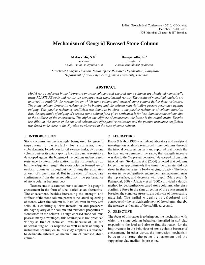
4. MODELLING DETAILS
Laboratory model is a cylinder of clay bed with a single
stone column or an encased stone column at the centre of
the bed which is loaded over an area using a rigid circular
plate covering some part of clay around the column. The
ideal finite element model to simulate the laboratory model
would be an axisymmetric continuum, which composes of
the clay bed, the stone column and the geogrid encasement.
The geometric details of a typical laboratory model and
the finite element idealisation are shown in Fig.1. Proper
boundary conditions are simulated, mesh is refined at the
interface between the stone column, the geogrid and the
clay and the part of clay bed near the loading plate. The
material properties of clay, stone and geogrid determined
experimentally are used as input parameters in the analysis.
Initial conditions for pore pressure and K0 conditions are
calculated.
Fig. 1: Typical Axisymmetric Model of clay and Columns
5. MECHANISM OF STONE COLUMN
Fig. 2 shows a typical deformed mesh of stone column bed
for a specified settlement. The stone column of diameter
‘d’ bulged laterally over a length of ‘4d’ of the column.
The magnitude of bulging of column both in the radial and
along the length of the column increased with settlement.
Fig. 2: Deformed Mesh of Stone Column Stabilised Bed
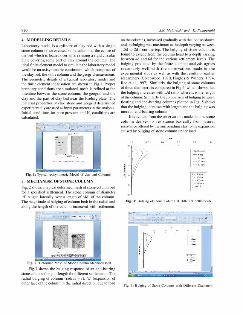
Fig.3 shows the bulging response of an end-bearing
stone column along its length for different settlements. The
radial bulging of column (radius = r), ‘x’ (expansion of
outer face of the column in the radial direction due to load
on the column), increased gradually with the load as shown
and the bulging was maximum at the depth varying between
1.5d to 2d from the top. The bulging of stone column is
found to extend from the column head to a depth varying
between 4d and 6d for the various settlement levels. The
bulging predicted by the finite element analysis agrees
reasonably well with the observations made in the
experimental study as well as with the results of earlier
researchers (Greenwood, 1970, Hughes & Withers, 1974,
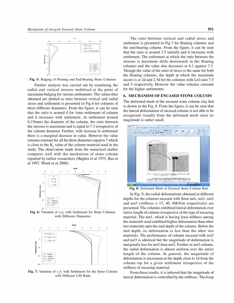
Rao et al, 1997). Similarly, the bulging of stone columns
of three diameters is compared in Fig.4, which shows that
the bulging increases with L/d ratio, where L is the length
of the column. Similarly, the comparison of bulging between
floating and end-bearing columns plotted in Fig. 5 shows
that the bulging increases with length and the bulging was
more in end-bearing column.
It is evident from the observations made that the stone
column derives its resistance basically from lateral
resistance offered by the surrounding clay to the expansion
caused by bulging of stone column under load.
0
2
4
6
8
10
0.0 0.2 0.4 0.6 0.8 1.0
x/r
L/d
fro
m t
op
5 mm
10 mm
15 mm
20 mm
Settlement
d = 30mm
D = 60mm
H = 300mm
L = 300mm
Ic = 0.25
Fig. 3: Bulging of Stone Column at Different Settlements
Fig. 4: Bulging of Stone Columns with Different Diameters
Mechanism of Geogrid Encased Stone Column 951
0
2
4
6
8
10
0.0 0.1 0.2 0.3 0.4 0.5
x/r
H/d
fro
m t
op
L/d = 5 (f)
L/d = 7.5 (f)
L/d = 10 (Endbearing)
d = 30mm
D = 60mm
H = 300mm
Ic = 0.25
Fig. 5: Bulging of Floating and End-Bearing Stone Columns
Further analysis was carried out by examining the
radial and vertical stresses mobilised at the point of
maximum bulging for various settlements. The values thus
obtained are plotted as ratio between vertical and radial
stress and settlement is presented in Fig.6 for columns of
three different diameters. From the figure, it can be seen
that the ratio is around 4 for 1mm settlement of column
and it increases with settlement. At settlement around
0.15times the diameter of the column, the ratio between
the stresses is maximum and is equal to 7.3 irrespective of
the column diameter. Further, with increase in settlement
there is a marginal decrease in value. However the value
remains constant for all the three diameters equal to 7 which
is close to the Kp value of the column material used in the
study. The observation made from the numerical studies
compares well with the mechanism of stone column
reported by earlier researchers (Hughes et al 1975, Rao et
al 1997, Wood et al 2000).
0
5
10
15
20
0 1 2 3 4 5 6 7 8
σσσσv/σ/σ/σ/σr
Set
tlem
ent
(mm
)
30
40
60
D = 2d
L = 300mm
H = 300mm
Ic = 0.25
d
Fig. 6: Variation of sv/s
r with Settlement for Stone Columns
with Different Diameters
0
5
10
15
20
0 1 2 3 4 5 6 7 8
σσσσv/σ/σ/σ/σr
Set
tlem
ent (m
m)
L/d = 5
L/d = 7.5
L/d = 10
d = 30mm
D = 60mm
H = 300mm
Ic = 0.25
Fig. 7: Variation of sv/s
r with Settlement for the Stone Column
with Different L/H Ratio
The ratio between vertical and radial stress and
settlement is presented in Fig.7 for floating columns and
the end-bearing column. From the figure, it can be seen
that the ratio is around 3.5 initially and it increases with
settlement. The settlement at which the ratio between the
stresses is maximum shifts downwards in the floating
columns and the value also decreases to 6.1 against 7.3.
Though the value of the ratio of stress is the same for both
the floating columns, the depth at which the maximum
occurs is at 2d and 2.5d for the columns with L/d ratio 7.5
and 5 respectively. However the value remains constant
for the higher settlements.
6. MECHANISM OF ENCASED STONE COLUMN
The deformed mesh of the encased stone column clay bed
is shown in the Fig. 8. From the figure, it can be seen that
the lateral deformation of encased column is not able to be
recognised visually from the deformed mesh since its
magnitude is rather small.
Fig. 8: Deformed Mesh of Encased Stone Column Bed
In Fig. 9, the radial deformations obtained at different
depths for the columns encased with three nets, net1, net2
and net3 (stiffness = 15, 40, 60kN/m respectively) are
presented. The columns exhibited lateral deformation over
entire length of column irrespective of the type of encasing
material. The net1, which is having least stiffness among
the materials used exhibited higher deformation than other
two materials upto the mid depth of the column. Below the
mid depth, its deformation is less than the other two
materials. The performance of column encased with net2
and net3 is identical but the magnitude of deformation is
marginally less for net3 than net2. Further in net3 column,
the radial deformation is almost uniform over the entire
length of the column. In general, the magnitude of
deformation is maximum at the depth close to 1d from the
column top for a given settlement irrespective of the
stiffness of encasing material.
From these results, it is inferred that the magnitude of
lateral deformation is controlled by the stiffness. The hoop
952 S.N. Malarvizhi and K. Ilamparuthi
force mobilised in the column material is shown in Fig. 10
for the encased columns. The hoop force is maximum at
depth around 1d and decreased with depth. This response
is seen in all the three columns irrespective of the stiffness
of the encasing material with higher hoop force in column
encased with material of higher stiffness. Maximum hoop
force is developed at the depth around 0.5d of the
encasement. For higher pressures, hoop forces are mobilised
over the entire length of the encasement.
0
2
4
6
8
10
0.00 0.02 0.04 0.06 0.08 0.10
x/r
L/d
fro
m top
net1
net2
net3
d = 30mm
D = 60mm
L = 300mm
H = 300mm
Ic = 0.25
Fig. 9: Radial Deformation of Encased Stone Columns
0
2
4
6
8
10
0.0 0.5 1.0 1.5 2.0
Hoop force (kN/m)
L/d
fro
m t
op
net1
net2
net3
d = 30mm
D = 60mm
L = 300mm
H = 300mm
Ic = 0.25
Fig. 10: Hoop Force Variation in Encased Stone Columns
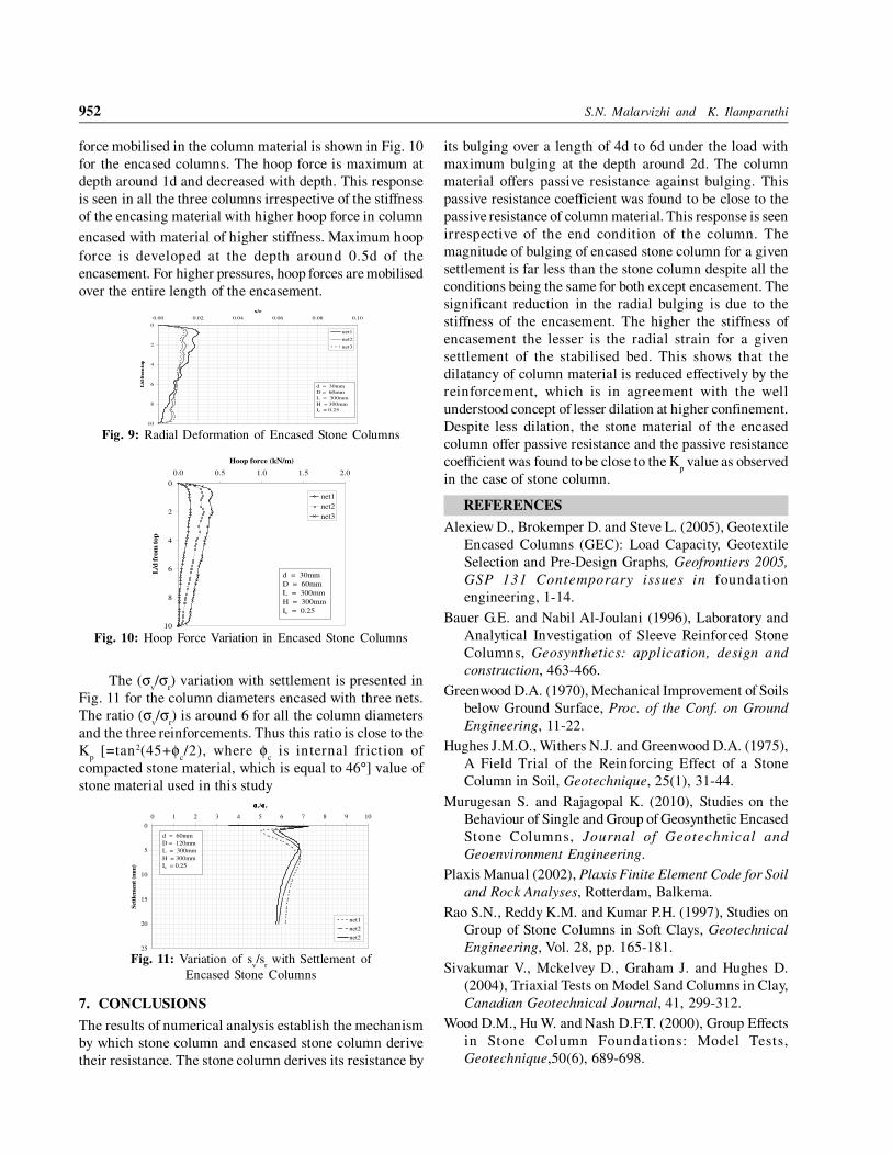
The (σv/σ
r) variation with settlement is presented in
Fig. 11 for the column diameters encased with three nets.
The ratio (σv/σ
r) is around 6 for all the column diameters
and the three reinforcements. Thus this ratio is close to the
Kp [=tan2(45+φ
c/2), where φ
c is internal friction of
compacted stone material, which is equal to 46°] value of
stone material used in this study
0
5
10
15
20
25
0 1 2 3 4 5 6 7 8 9 10
σσσσv/σσσσr
Sett
lem
en
t (m
m)
net1
net2
net2
d = 60mm
D = 120mm
L = 300mm
H = 300mm
Ic = 0.25
Fig. 11: Variation of sv/s
r with Settlement of
Encased Stone Columns
7. CONCLUSIONS
The results of numerical analysis establish the mechanism
by which stone column and encased stone column derive
their resistance. The stone column derives its resistance by
its bulging over a length of 4d to 6d under the load with
maximum bulging at the depth around 2d. The column
material offers passive resistance against bulging. This
passive resistance coefficient was found to be close to the
passive resistance of column material. This response is seen
irrespective of the end condition of the column. The
magnitude of bulging of encased stone column for a given
settlement is far less than the stone column despite all the
conditions being the same for both except encasement. The
significant reduction in the radial bulging is due to the
stiffness of the encasement. The higher the stiffness of
encasement the lesser is the radial strain for a given
settlement of the stabilised bed. This shows that the
dilatancy of column material is reduced effectively by the
reinforcement, which is in agreement with the well
understood concept of lesser dilation at higher confinement.
Despite less dilation, the stone material of the encased
column offer passive resistance and the passive resistance
coefficient was found to be close to the Kp value as observed
in the case of stone column.
REFERENCES
Alexiew D., Brokemper D. and Steve L. (2005), Geotextile
Encased Columns (GEC): Load Capacity, Geotextile
Selection and Pre-Design Graphs, Geofrontiers 2005,
GSP 131 Contemporary issues in foundation
engineering, 1-14.
Bauer G.E. and Nabil Al-Joulani (1996), Laboratory and
Analytical Investigation of Sleeve Reinforced Stone
Columns, Geosynthetics: application, design and
construction, 463-466.
Greenwood D.A. (1970), Mechanical Improvement of Soils
below Ground Surface, Proc. of the Conf. on Ground
Engineering, 11-22.
Hughes J.M.O., Withers N.J. and Greenwood D.A. (1975),
A Field Trial of the Reinforcing Effect of a Stone
Column in Soil, Geotechnique, 25(1), 31-44.
Murugesan S. and Rajagopal K. (2010), Studies on the
Behaviour of Single and Group of Geosynthetic Encased
Stone Columns, Journal of Geotechnical and
Geoenvironment Engineering.
Plaxis Manual (2002), Plaxis Finite Element Code for Soil
and Rock Analyses, Rotterdam, Balkema.
Rao S.N., Reddy K.M. and Kumar P.H. (1997), Studies on
Group of Stone Columns in Soft Clays, Geotechnical
Engineering, Vol. 28, pp. 165-181.
Sivakumar V., Mckelvey D., Graham J. and Hughes D.
(2004), Triaxial Tests on Model Sand Columns in Clay,
Canadian Geotechnical Journal, 41, 299-312.
Wood D.M., Hu W. and Nash D.F.T. (2000), Group Effects
in Stone Column Foundations: Model Tests,
Geotechnique,50(6), 689-698.