Embed Size (px)
Citation preview

G R A V I T Y / G E O G R I D
Manufactured by:LIBERTYSTONE™HARDSCAPING SYSTEMS
LIBERTYSTONE™HARDSCAPING SYSTEMS www.liberty-stone.net

1
Design Advantage· CornerStone® units are made from high compression and low-absorption concrete, that provides durability and resistance to weathering.
· CornerStone’s large hollow core reduces efflorescence problems and the use of costly pigments.
· CornerStone® units provide excellent solutions for gravity, geogrid reinforced, steel/concrete, plantable and other types of wall structures.
· CornerStone® provides superior environmental advantages both by using less concrete in manufacturing and by the resulting efficiency of transportation.
· CornerStone® provides superior flexibility in creating curves, corners, steps and terraced walls.
Installation Advantage· A small crew can easily install 200 to 600 square feet of wall units a day.
· One person can easily handle the light weight hollow core CornerStone® unit.
· The one-step SecureLug system outperforms the pins or clip method, speeding up installation time considerably.
· The hollow core makes it easy to saw cut, add special lighting or place fence posts into when adding creative details.
Economic Advantage · CornerStone® system will save time, labor, and material costs.
· CornerStone® walls can cost considerably less than conventional cast in place concrete walls or traditional masonry systems.
· CornerStone® light-weight, hollow core units are less expensive to ship and handle.
· CornerStone® labor and equipment costs are low because no special equipment is required and semi-skilled workers will find the units easy to assemble.
*all dimensions vary between manufacturers. Verify with local producer for correct measurements
The CornerStone® retaining wall system was developed with the installer in mind. CornerStone’s durable, high shear strength concrete SecureLugs fit into lower units’ hollow cores, allowing significant lateral movement without losing unit to unit interlock. Tapered sides with removable wings make it easy to build tight curves and straight walls with complete accuracy. CornerStone’s large hollow core, filled with gravel, provides a superb geogrid to block connection.
CornerStone® is committed to providing complete technical and construction information to installers and engineers to ensure the successful completion of any retaining wall project. Your best choice is CornerStone® for value, beauty, durability, ease of construction, and complete retaining wall excellence.
cap
3" Height x 18" Width x 12" Depth(76 H x 457 W x 305 mm D)Weight: 51 lbs (23 kgs)
90 degree corner
8" Height x 18" Width x 9" Depth(203 H x 457 W x 229 mm D)Weight: 65 lbs (29 kgs)
straight Face
8" Height x 18" Width x 12" Depth (203 H x 457 W x 305 mm D) Weight: 75 lbs (34 kgs) Face Area = 1 sq. ft.
radius Face
8" Height x 17.325" Width x 12" Depth (203 H x 440 W x 305 mm D) Weight: 75 lbs (34 kgs) Face Area = .96 sq. ft.
Dimensions 8" Height x 18" Width x 12" Depth (203 H x 457 W x 305 mm D)Face area 1 sq ft (0.093 m2)soliD Volume .605 ft3 (0.017 m3)Volume oF VoiDs .395 ft3 (.0111 m3)
Weight 75 lbs (34 kgs)Faces VariesgraVel FilleD Weight 125 lbs (57 kgs)concrete FilleD Weight 135 lbs (61 kgs)Batter/setBack 4.5° 5/8"/Unit
note: bolded terms are defined in our online glossary at www.cornerstonewallsolutions.com
CoRNERSToNE® ovERvIEw

2
CoRNERSToNE ® 100 INSTAllATIoN guIDE gRAvITy/gEogRID
TAblE oF CoNTENTS
Installation Step by Step
Gravity Wall
Geogrid Reinforced Wall
CornerStone® 100 Wall Details
Base Elevation Changes
Convex/Outside Curves
Concave/Inside Curves
Outside Corner
Inside Corner
Stair Details
Pillar Details
Estimating Charts
3
11
14
15
16
17
18
19
20
25
27

3
gRAvITy CoRNERSToNE® wAll
Gravity (SRW) segmental retaining wall systems are structures lower in height that use the CornerStone® unit weight combined with gravel core infill to resist earth pressures behind and on top of the wall. The 5/8"/unit (4.5 degree or 1"/vertical foot) batter or setback of the CornerStone® wall along with proper soil conditions below and behind the wall provide the stability of the structure. For walls 4.0ft (1.2m) and taller a qualified engineer should be consulted.

Embedment Depth
Excavated MaterialsSub base
Retained Soil
leveling Pad Trench
back of wall Excavation Depth
Excavation Cut line
Stakes Proposed wall location
grass
Reinforced backfill Zone
organic Materials
Compactor
Trench width +/- 3.0 ft
Sub base
4
STEP 2 excavation
· Excavate and prepare Sub Base Leveling Pad Trench 6" below first course
· Leveling Pad trench is approximately 2.5' to 3' wide
· Normal wall Burial Depth or Embedment Depth is 6" to 12" or one block (for more
information refer to design manual)
· Excavate cut line to a 2 to 1 slope or greater
· Back of wall excavation depth into the bank should be 12" beyond the back of the
Sub Base Leveling Trench
STEP 1planning
· Mark the bottom and top of the wall excavation location with spray paint or stakes
· Establish proper elevation bottom and top of wall before excavating
· Organic Materials should not be used in Structural Backfill Zone
· Store and protect Structural Backfill Materials from inclement weather
during construction
STEP 3suB Base coMpaction
· Compact Sub Base to 95% Standard Proctor Density or greater
· Remove any Organic or poor soils in the Sub Base and replace with proper Structural
Fill Materials before compacting
CoRNERSToNE ® 100 INSTAllATIoN guIDE gRAvITy

CompactorCompacted gravel leveling Pad
Rake for Rough grading
well graded gravel Approx +/- 6" Deep
leveling Pad Trenchbase Stabilization Fabric
Trench Depth 6"
5
STEP 4Base staBilization
· (Optional) place 5' to 6' wide Base Stabilization Fabric on top of leveling
pad trench
· Base Stabilization Fabrics will help prevent sub base materials from mixing with the gravel
base leveling pad during compaction
· Fabric also provides extra Structural Bearing Stability to the base leveling pad
STEP 5 rough leveling pad
· Place Well Graded Gravel (also known as Road Base Aggregates) on top of fabric in the
leveling pad trench approximately 6" deep
· Rough grade gravel with a rake close to finish base elevation
STEP 6 coMpact leveling pad
· Compact the Gravel Leveling Pad to 95% Standard Proctor Density or greater
· Correct Moisture Content in the gravel will help in reaching proper compaction
CoRNERSToNE ® 100 INSTAllATIoN guIDE gRAvITy

Compacted gravel leveling Pad
Screed PipeScreed board or Straight Edge
2' level4' level
Compacted gravel leveling Pad
Screed Pipe ShovelScreed Pipe
Extra gravel
Screed Pipe
Screed board or Straight EdgeScreed leveling Pad
6
STEP 7 level screed pipes
· Place first 3' long Screed Pipe across the trench at one end of the wall or at
the lowest elevation
· Scratch a trench for the pipe in the compacted gravel with a chipping hammer
· Use a 2' level or Laser Level to set the screed pipe to the proper level
· Gravel is added underneath and around the screed pipe to support while leveling
· Place the second screed pipe across the trench approximately 9' from the first screed pipe
· Level the second screed pipe to the same elevation as the first screed pipe by using a 4'
level on top of a Screed Board, Straight Edge or with a Laser Level
· Continue to place and level screed pipes the full length of the trench leveling pad or until
reaching a base elevation change
STEP 8extra gravel
· Place or remove extra Well Graded Gravel (also known as Road Base Aggregates) level
to the top of the screed pipes as needed
· (If more than 1 ½ inches of loose gravel is added, repeat the compaction steps again
before screeding)
STEP 9screeding leveling pad
· Screed the gravel leveling pad with a Screed Board or Straight Edge across the trench on
top of two screed pipes
· The coarser the gravel the more back and forth the screeding action when drawing the
Screed across the leveling pad
· Too much pressure on the screed straight edge may dislodge the level of the screed
pipes while screeding
· A second screed pass may be needed to insure an accurate level has been achieved
· Continue to screed the leveling pad until completing the full length of the
trench or up to the first elevation change
CoRNERSToNE ® 100 INSTAllATIoN guIDE gRAvITy
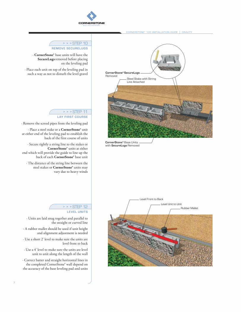
cornerstone® base units with securelugs Removed
Steel Stake with String line Attached
cornerstone® securelugs Removed
level Front to back
level unit to unitRubber Mallet
7
STEP 10reMove securelugs
· CornerStone® base units will have the SecureLugs removed before placing
on the leveling pad
· Place each unit on top of the leveling pad in such a way as not to disturb the level gravel
STEP 11lay First course
· Remove the screed pipes from the leveling pad
· Place a steel stake or a CornerStone® unit at either end of the leveling pad to establish the
back of the first course of units
· Secure tightly a string line to the stakes or CornerStone® units at either
end which will provide the guide to line up the back of each CornerStone® base unit
· The distance of the string line between the steel stakes or CornerStone® units may
vary due to heavy winds
STEP 12level units
· Units are laid snug together and parallel to the straight or curved line
· A rubber mallet should be used if unit height and alignment adjustment is needed
· Use a short 2' level to make sure the units are level front to back
· Use a 4' level to make sure the units are level unit to unit along the length of the wall
· Correct batter and straight horizontal lines in the completed CornerStone® wall depend on
the accuracy of the base leveling pad and units
CoRNERSToNE ® 100 INSTAllATIoN guIDE gRAvITy

STEP 14drain pipe outlet
· Perforated Drain Pipe should have adequate slope to drain water in the right direction
towards each Drain Pipe Outlet
· Drain Pipe Outlet can be every 30 or 50 feet
· Perforated Drain Pipe can be a Sock Wrapped system to help prevent
fines from migrating into the pipe
8" liftsburial Depth
Compact the backfill Materials before Inserting Drainage gravel
hand CompactorImpermeable Material
Toe of wall
hollow CoreImpermeable Material
Perforated Drain Pipe Drain Pipe outlet
Slope
Cut 4" Square out of bottom cornerstone®
Slope
8
STEP 13iMperMeaBle Fill
· Backfill behind, in front (toe of wall) and in the hollow cores of the units with
Impermeable Materials up to the desired level of the Perforated Drain Pipe or to the top of
the first course
· Compact the impermeable materials behind, in front and in the hollow cores of the units
· Sweep the top of the units clean of all rock and dirt before placing the next course of units
· Sweeping should create a 1⁄2" void in the core to accommodate the SecureLug’s interlock
STEP 15 BackFill
· Place and compact Backfill Materials in maximum Lifts of 8"
· Lifts may be less than 8" depending on the type of soil or size of equipment
· Backfill materials will be placed 6" to 12" behind the units allowing for Clear Crush
Drain Gravel (Angular Aggregates free of fines) between the CornerStone® units and compacted
backfill materials
By adding Clear Crush Drain Gravel (Angular Aggregate free of fines) after
compaction of the backfills materials, this will prevent undue pressure against the wall
which can cause the units to move out of alignment
· Each lift should be compacted to 95% Standard Proctor or greater
· The correct Moisture Content in the Backfill Materials will help in reaching
proper Compaction Density
CoRNERSToNE ® 100 INSTAllATIoN guIDE gRAvITy

Clear Crush Drain gravel Placed Flush to Top of unitsbroom
Reinforced backfill MaterialsClear Crush Drain gravel Placed Flush to Top of units
broom
Reinforced backfill Materials
Perforated Drain Pipe
grout Around Drain Pipe outlet
cornerstone® Course 3
Clear Crush Drain gravel
9
STEP 16drainage gravel
· Clear Crush Drain Gravel (Angular Aggregates free of fines) is placed in the hollow
cores and 6" to 12" behind the wall units after compaction of the Backfill Materials. This will
prevent undue pressure against the wall which can cause the units to move out
of alignment
· Clear Crush Drain Gravel does not need to be compacted
· Sweep the top of the CornerStone® units clean of all rock and dirt before placing the
next courses
· Make sure the Clear Crush Drain Gravel directly behind the wall units is placed flush to
the top of the units
· Make sure the Backfill Materials are as well compacted and level as possible
STEP 17continue installation
· Continue to install each course of units following the same steps as above
· Install and compact Backfill Materials in 8" lifts until wall is complete
· Grout around Drain Pipe Outlet to prevent Clear Crush Drain Gravel or Drainage
Aggregates (Angular Aggregates free of fines) from migrating
CoRNERSToNE ® 100 INSTAllATIoN guIDE gRAvITy

*Final determination of the suitability of the contemplated use, and its manner of use are the sole responsibility of the user
cornerstone® Cap unit & Concrete Adhesive
Soil Separating Filter Fabric
10
STEP 18capping
· Complete the top of the wall with CornerStone® cap units
· Properly secure the cap units using a Concrete Adhesive
· Make sure all units are free of dirt and stones before installing the caps
· Place a solid bead of Concrete Adhesive around the top of each CornerStone® unit
· Place a bead of adhesive between each joint of the cap units
STEP 19 soil separation FaBric
· Place a 6 ft wide Soil Separating Filter Fabric on top of the backfill and drainage
gravel and against the back of the last units before placing the planting soils
· The fabric will prevent planting soil fines from staining the face of the wall and
migrating into the Clear Crush Drain Gravel (Angular Aggregate free of fines)
STEP 20 Final grading
· Insure that final grading is done on top and bottom of the wall
· Make sure to protect newly placed planting soil from erosion during heavy rains or
surface runoff
CoRNERSToNE ® 100 INSTAllATIoN guIDE gRAvITy

11
gEogRID REINFoRCED CoRNERSToNE® wAll
Creating a CornerStone® reinforced wall system, involves the use of geogrids for reinforcement. CornerStone® walls 4.0ft (1.2m) and taller will automatically have active pressures because of their height. Walls smaller than 4.0ft (1.2m) may also require geogrid reinforcement depending on other related factors. Parking lots, roadways, or positive slopes above walls for example, require the use of reinforcement to help resist the increased pressure behind the wall. Geogrid used with the appropriate lengths, layers, and compacted backfill materials will resist these active forces above and behind the wall. For walls 4.0 ft and taller a qualified engineer should be consulted.

Embedment Depth
Excavated MaterialsSub base
Retained Soil
leveling Pad Trench
back of wall Excavation Depth
Excavation Cut line
geogrid Reinforcement
geogrid Reinforcement Cut in lengths Designed by Engineer
geogrid Strength orientation
CoRNERSToNE ® 100 INSTAllATIoN guIDE gEogRID REINFoRCED
STEP 1planning
· Excavate and prepare Sub Base Leveling Trench 6" below first course
· Leveling Pad Trench is approximately 2.5' to 3' wide
· Normal wall Burial Depth or Embedment Depth is 6" to 12" or one block (for more
information refer to design manual)
· Excavate cut line to a 2 to 1 slope or greater
· Back of wall excavation depth into the bank at the base of the wall should be from the face
of wall to the designed length of Geogrid
STEP 2cut geogrid
· Cut Geogrid Reinforcement to the length specified in the design
· Geogrids are manufactured in two directions Uni-axial or Bi-axial. Uni-axial grid has one direction of strength and that direction has
to be oriented perpendicularly to the face of the wall during installation. Bi-axial grid can be laid in two directions, perpendicular
and lengthwise to the face of wall (ensure that the lengthwise direction is still
in accordance to the length specified by the Engineer’s design)
· Correct geogrid orientation, strength and length is crucial to the success
of the wall project
· Each geogrid length should be laid parallel and adjacent to each other but never
overlapping
Correct geogrid orientation
12

8" liftsDrain Pipe outlet
Reinforced Zone
Tensioned geogridStakes Placed to Maintain geogrid Tension
Clear Crush Drain gravel
geogrid Elevations Set to Engineer Design
13
CoRNERSToNE ® 100 INSTAllATIoN guIDE gEogRID REINFoRCED
STEP 3 lay geogrid
· Place the geogrid as far forward on the CornerStone® units as possible without
revealing it on the face
· Place the next course of CornerStone® units on top of the lower units and
geogrid at a half bond
· The two SecureLugs will fit securely into the hollow cores of the two units below and lock
the geogrid into the gravel core
· Pull the unit forward to engage and align the SecureLugs
· Complete the installation of units on the Geogrid Reinforced courses
· Make sure each unit is installed against the next unit leaving no gaps between unit joints
· Tension the geogrid in such a way as NOT to disturb the alignment of the upper units
· Use stakes or backfill materials to maintain the tension during backfilling
· Do not drive equipment directly on top of geogrid
STEP 4reinForced BackFill
· Backfill and Compact the Reinforced Zone by placing materials from the back of
the wall towards the end of the geogrid
· Install drainage gravel in the cores and 6" to 12" behind the units after placing and
compacting backfill materials
· Install and compact backfill materials in 8" Lifts until wall is complete

14
This section provides detailed, illustrated step-by-step instructions for using CornerStone® 100 to construct wall details including: inside curves, outside curves, elevation changes, and both inside and outside corners.
Curves, corners and elevation changes are the portions of a wall project that adapt to the specifics of the site and the needs of its users. Correct construction and professional completion of these wall details greatly enhances the visual appeal of the finished project and avoids the time and costs associated with improper installation.
CoRNERSToNE® 100 wAll DETAIlS

Top of base unit base leveling Pad
well CompactedFirst unit Second Course
Second unit one securelug Removed
Third unit both securelugs Removed
Corner unit
Capping units Attached with Concrete Adhesive
15
STEP 1Base elevation changes
· The top of the installed base unit will be used to establish the step up gravel leveling
pad elevation
· Make sure to backfill and compact the gravel in and around the last unit of the first course
· Finished grade of the leveling pad should be an 1/8" to 1/4" above top of first course units
to allow for a small amount of settlement
· Repeat the above screeding steps on the second elevation gravel
leveling pad
· Place the first unit on the second course at a half bond on top of last & second last of the
first course units
· The two SecureLugs will fit into the hollow cores of the two units below. To align the wall, place a string line at the back of the units for a
straight wall or place a PVC pipe for a curved wall
· Pull upper unit forward to engage and align units
· The batter or set back will be 5/8"/unit (4.5 degree or 1"/vertical foot)
· Place the second unit half on the last unit and half on the second gravel leveling pad.
Ensure that the SecureLug is removed on the leveling pad side of the unit
CoRNERSToNE ® 100 INSTAllATIoN guIDE wAll DETAIlS

STEP 1convex First course
· If possible, start building a curve from the center and work left and right
through the curve
· Use PVC Flex Pipes to create smooth and accurate Convex curves
· Use the back of the unit for alignment
· Remove one or both CornerStone® wings when building a Convex curve
· Build each course of units by starting at the same place and the same bond
as the last course
· Convex curves have a slight increase in batter or setback to the standard 5/8"
· The taller the wall the larger the Convex first course needs to be. The radius of each
additional course will be slightly smaller than the lower course
· CornerStone® minimum Concave curve is approximately 3.6 foot radius
Convex/Outside Curves
STEP 2convex geogrid curve
· Each geogrid length should be laid perpendicularly to the wall face
· Geogrid should not overlap on the CornerStone® units
· Correct geogrid orientation, strength and length is crucial to the success
of the wall project
PvC Flex Pipe
First Course
Smaller Radius
larger Radius
work left
Start Center of Curve
work Right
+/- 3" (75mm) backfill Materials between geogrid overlaps
Do Not overlap geogrid on cornerstone® units
Center of Curve
Min Convex Radius 3.6' (1.1m)
wings Removed
CoRNERSToNE ® 100 INSTAllATIoN guIDE ouTSIDE CuRvES
16

17
STEP 1concave First course
· If possible, start building a curve from the center and work left and right
through the curve
· Use PVC Flex Pipes to create smooth and accurate Concave curves
· Use the back of the unit for alignment
· Build each course of units by starting at the same place and the same bond as
the last course
· Concave curves have a slight decrease in batter or setback to the standard 5/8"
· The taller the wall the smaller the Concave first course needs to be. The radius of each
additional course will be slightly larger than the lower course
· CornerStone® minimum Concave curve is approximately 3.6 foot radius
STEP 2concave geogrid curve
· Each geogrid length should be laid perpendicularly to the wall face
· Geogrid should not overlap on the CornerStone® units
· To ensure 100% coverage, place a second layer of geogrid centered to the unreinforced
triangle zone one course above the main geogrid layer
· Correct geogrid orientation, strength and length is crucial to the success of the
wall project
PvC Flex Pipe
Center of Curve
First Course
Min
Convex R
adius
3.0' (0.9m)
unreinforced Triangle Zone
work leftStart Center of Curve
work Right
Main geogrid layer
geogrid Placed at Center to unreinforced Triangle Zone
Secondary geogrid layer
larger Radius
Smaller Radius
Concave/Inside Curves
CoRNERSToNE ® 100 INSTAllATIoN guIDE INSIDE CuRvES

STEP 1outside First course
· Use a 90° Corner unit to build an outside corner
· Place the first 90° Corner unit on the base leveling pad to start the outside corner
· Place a CornerStone® unit on either side against the 90° Corner unit
· Continue to lay the CornerStone® base course on either side of the corner until first
course is completed
· Flip and turn the second course 90° Corner overlapping the short side and half of the
CornerStone® base unit. This unit should be pushed back 5/8" to achieve proper setback
· Continue to lay the CornerStone® second course on either side of the
corner until second course is completed
· The 90° Corners can be glued or concrete core filled to ensure a proper course to
course outside corner interlock
Outside Corner
STEP 2outside geogrid corner
· Each geogrid length should be laid perpendicularly to the wall face
· Geogrid should not overlap on the CornerStone® units
· Lay the 1st geogrid corner section perpendicularly to one side of the corner
· Lay the 2nd geogrid section perpendicularly to the other side of the corner but not
overlapping the 1st geogrid section
· Lay the secondary geogrid layer one course above and perpendicular to the lower main
geogrid layer directional strength
· Correct geogrid orientation, strength and length is crucial to the success
of the wall project
1st Course
90˚ Corner
3rd Course Same as 1st Course
2nd Course
90˚ Corner Flipped and Turned
2nd geogrid Corner Section geogrid layers
Should Not overlap
1st geogrid Corner Section
Secondary geogrid layer (one Piece)
Main geogrid layer
90˚ Corner
5/8" Setback
18
CoRNERSToNE ® 100 INSTAllATIoN guIDE ouTSIDE CoRNERS
Adhesive Can be Applied to Corner units

19
STEP 1inside First course
· Place the second unit at right angle and centered to the first CornerStone® base unit. Continue to install the CornerStone®
base units right and left of the first inside corner units
· Place the second unit at right angle and centered to the 1st unit on the second course
· Make sure second course units are placed at a 5/8" setback to the lower inside corner
· Continue to install the units left and right of the inside corner to complete the second
course of the wall
· Repeat the above step by step installation until the wall height is completed or until
reaching the first geogrid layer
Inside Corner
STEP 2inside geogrid corner
· Each geogrid length should be laid perpendicularly to the wall face
· Geogrid should not overlap on the CornerStone® units
· Lay the 1st geogrid corner section perpendicularly to one side of the corner and
overlap h/4 through the backfill (Height of Wall ÷ 4)
· Lay the 2nd geogrid section perpendicularly to the 1st geogrid
· Lay the second geogrid layer perpendicularly and overlap h/4 through the backfill opposite
to the first geogrid layer
· The h/4 overlap will alternate layer to layer to properly secure the inside corner
· Correct geogrid orientation, strength and length is crucial to the success of the
wall project
2nd base unit Centered
1st base unit
2nd unit Centered
5/8"
1st
1st geogrid Sectionheight/4 overlap Through the backfill
2nd geogrid Section
Second geogrid Section
Second Course Staggered 5/8"
First geogrid layer
Second geogrid layer
CoRNERSToNE ® 100 INSTAllATIoN guIDE INSIDE CoRNERS

CoRNERSToNE® 100 STAIR DETAIlS
Proper installation of stairs in a wall project requires the same care and thoroughness as the creation of the wall itself. CornerStone’s design features including the hollow core, and SecureLug simplify the process and provide installers with a range of options to create stairs that are striking and unique. This section provides illustrated step-by-step instructions for using CornerStone® 100 to construct stair details.
20

gravel Filled wall unitsbackfill and Compact
First Course buriedhollow Core Step units
Second Course wall unitsback to back units
half bond
First Course buried
21
STEP 1 Base leveling pad
· When building steps, exercise the same care used in typical wall construction
· Prepare the sub-base and base leveling pad by following Gravity CornerStone® Installation
Steps 1 to 9
· Build each step in sequence with each course of the regular wall units for best results of wall
to step interlock
STEP 2 lay First course
· CornerStone® first base units will have the SecureLugs removed before placing on the
leveling pad
· First course of step units will be totally buried
· Backfill behind the first course units with gravel, then compact and level flush to the top
of the first course
· Do not fill the step units’ hollow cores with gravel if you plan to use concrete
STEP 3 lay second course
· Place the second course of units on top of the base units
· Place a second row of units back to back behind the second course of units on
half bond
· Backfill behind the second course of units with gravel, then compact and level flush to
the top of the second course
· Do not fill the step units’ hollow cores with gravel if you plan to use concrete
CoRNERSToNE ® 100 INSTAllATIoN guIDE STAIR DETAIlS

backfill and Compact behind units
Third Course90° Corner
1.5" Forward batter
securelug Interlock
backfill and Compact Stair Tread
2222
STEP 5 continue installation
· Continue to install each course of step units following the same steps as above
· The top and final step does not need backward units
STEP 4 lay third course
· Place the third course of units on the lower backward facing units with the SecureLugs
placed into the 2 hollow cores of the lower units on half bond
· Pull the units forward to lock the SecureLugs into the lower backward units
· The third course units will be in a forward batter approximately 1.5 inch leaving 10.5
inches exposed on the front first step
· Place a second row of units back to back behind the third course of units on half bond
CoRNERSToNE ® 100 INSTAllATIoN guIDE STAIR DETAIlS

Stair Returns walls Near vertical1.5" overhang
Stair Tread Caps
Concrete Adhesive
12" (300mm) Tread 8" (200mm) Riser
Typical wall ConstructionFourth Course
gravel Filled wall units
backfill and Compact behind unitsConcrete Core Fill All Step units
23
STEP 7 stair treads
· CornerStone® 12 inch deep cap units can be used as a stair tread
· Option: Pavers, Patio Slabs or Natural Stone can also be used as a stair tread
STEP 6 concrete core steps
· Concrete filling the cores of all the step units will provide for greater stair stability
· Concrete core fill flush to the top of the units
· Use a steel bar to hand vibrate the cores to insure proper filling
· Option: Unit cores can be filled with gravel but must be well compacted
CoRNERSToNE ® 100 INSTAllATIoN guIDE STAIR DETAIlS

1.5" overhangConcrete Core Fill All Step units
backwards buried unitsConcrete between units
15" (380mm) Tread6" (150mm) Riser
3" (76mm) Cap
Concrete Core Fill All Step units
12" (300mm) Tread8" (200mm) Riser
24
STEP 8 8" riser cross section
· The 12 inch cap will overhang the step units by approximately 1.5 inch on each step
· The riser will be a full 8 inches using the above installation
· Properly secure the cap units using a concrete adhesive
· Make sure all units are free of dirt and stones before installing
· Place a bead of adhesive between each joint of the caps
STEP 9 loWer step risers
· Lower risers can be made such as 6" or 7" by lowering the buried units 1 to 2 inches below
the top of the backward buried unit
· Larger treads can be created by moving the buried units back off the forward step course 3
to 4 inches to create a 15 to 16 inch tread
· A variety of riser heights and tread lengths can be created to suit your project
CoRNERSToNE ® 100 INSTAllATIoN guIDE STAIR DETAIlS
8" Riser x 12" Tread
6" Riser x 15" Tread

25
Pillars add a finishing touch of elegance to any CornerStone® wall project. They can be used to create distinguished entranceways to any residence or business and the unit’s hollow cores greatly simplify the placement of lighting in the pillars. This section provides simple instructions for the creation of a 27" pillar.
CoRNERSToNE® PIllAR DETAIlS

Compact to 95% Standard Proctor DensitySub base leveling Pad 14" below Finished grade
Concrete Adhesive
gravel Filled CoresFlip and Turn
overlapping bonds on Each Course
Pillar Cap 32" (508mm)
27"
27"
leveling Padbase Stabilization Fabric
26
STEP 1 leveling pad
· Excavate and prepare your Sub Base Leveling Pad
· Install leveling pad of well graded gravel (also known as road base aggregates)
a minimum of 8" (200 mm) thick and 40" (1000 mm) square. Compact to 95%
standard proctor density
· Install the first 4 corner units perpendicular and square to each other
· Ensure first base course is level and square to the center of the pad
· Bury the first course completely for stability
CoRNERSToNE ® 100 INSTAllATIoN guIDE P IllAR DETAIlS
STEP 2 second course
· Place second course of the CornerStone® 90° Corner units directly on top of the
first course
· Flip and turn the second course corner units upside down to create an overlapping bond
· Clear Crush Drain Gravel (Angular Aggregates free of fines) should be placed in
the cores and middle of pillar
· (concrete core filling optional) use a dry concrete mix to prevent leaching of cement
· Concrete Adhesive should be applied to all units to ensure course to course interlock
90 degree corner
8" Height x 18" Width x 9" Depth (203 H x 457 W x 229 mm D)Weight: 65 lbs (29 kgs)27" Pillar
STEP 3 additional courses
· Repeat Step 1 and Step 2 until desired height of pillar has been reached
STEP 4 coMpletion
· Complete the pillar with a Pillar Cap
· Secure the Pillar Cap with a concrete adhesive
*Pillar cap approximately 32" (508mm)

ESTIMATINg ChARTS
The soil friction angle in these charts is used to calculate the pressure soil will have on a CornerStone® Geogrid reinforced wall. This guide outlines 26, 30 & 34 degree friction angle soil types. Additionally, three different top-of-wall load conditions are used in each of the soil types i.e. no surcharge load, 100 psf load and a 3 to 1 slope.
The assumed weight for the three soil types is approximately 120 lb/ft3 (19kN/m3). A well graded gravel leveling pad with a minimum of 1 (8”) unit of burial is assumed for base sliding resistance. All sub base, leveling pad and backfill materials should be compacted to a minimum of 95% Standard Proctor.
The CornerStone® concrete SecureLug has a built in batter or set back of 4.5 degrees or 1”/vertical foot of wall.
For more specific soil analysis refer to our website, or consult a qualified engineer.
These preliminary design charts are used by owner, designer, architect and installer to calculate construction cost only and are not for construction purposes. A qualified engineer should be consulted for a final construction design.
27
geogrid reinForced cross section
geogrids Geogrids are meshes typically made of a regular pattern of tensile elements usually made of a fairly rigid type of plastic. These are used to strengthen fill materials in geotechnical applications. They provide increased shear strength between soil strata interfaces. Their tensile strength can prevent or decrease the degree of differential settlement in some applications such as beneath structures or roads by transmitting the load over a broader area of soil, thereby diminishing the vertical stress — and subsequent compression — in the soil.

28
CoRNERSToNE ® 100 INSTAllATIoN guIDE ESTIMATINg ChARTS
The above charts are intended for preliminary estimation only and all designs must be reviewed by a professional engineer. Use of the charts are the sole responsibility of the user. CornerStone Wall Solutions Inc. assumes no liability for improper use of the charts.
Approximate Equivalent Geogrids:
SRW: 3 Series, Strata: SG150, Synteen: SF20, Mirafi: 2XT, Tensar: BX1200, Luckenhaus/Raugrid: 3/3-20, Huesker/Fortrac: 35/20-20
DO NOT USE FOR CONSTRUCTION / FOR PRELIMINARY ESTIMATION ONLY
26 Degree Soil
CornerStone 100Case A & B
CornerStone 100Case ECornerStone 100Case A & B
CornerStone 100Case E
CornerStone 100Case A & B
CornerStone 100Case E
4’0”4’0”
4’0”4’0”
4’6”
4’6”
4’6”
6’0”
5’9”
5’9”
5’9”
7’3”
5’0”
5’0”5’0”
4’0”4’0”
4’3”
4’0”
5’9”
4’6” 5’9”
5’9”
5’3”
7’3”
5’9”
6’6”
8’9”
6’3”
4’0”4’3” 5’0”
5’0”
4’6” 6’3” 8’3”
6’3”
6’9”
8’3”
8’3”
8’6”
5’9”
Case A Exposed Hgt wo/cap 2'0" 2'8" 4'0" 4'8" 6'0" 8'0" Grid Sq Yd per Ln Ft 0.444 0.444 0.944 1.000 1.667 2.722 # Block per Ln Ft 2.67 3.33 4.67 5.33 6.67 8.67 # Cap per Ln Ft .67 .67 .67 .67 .67 .67
4’0”4’0”
4’0”4’0”
4’6”
4’6”
4’6”
6’0”
5’9”
5’9”
5’9”
7’3”
5’0”
5’0”5’0”
4’0”4’0”
4’3”
4’0”
5’9”
4’6” 5’9”
5’9”
5’3”
7’3”
5’9”
6’6”
8’9”
6’3”
4’0”4’3” 5’0”
5’0”
4’6” 6’3” 8’3”
6’3”
6’9”
8’3”
8’3”
8’6”
5’9”
Case b Exposed Hgt wo/cap 2'0" 2'8" 4'0" 4'8" 6'0" 8'0" Grid Sq Yd per Ln Ft 0.556 1.000 1.083 1.611 1.889 3.611 # Block per Ln Ft 2.67 3.33 4.67 5.33 6.67 8.67 # Cap per Ln Ft .67 .67 .67 .67 .67 .67
4’0”4’0”
4’0”4’0”
4’6”
4’6”
4’6”
6’0”
5’9”
5’9”
5’9”
7’3”
5’0”
5’0”5’0”
4’0”4’0”
4’3”
4’0”
5’9”
4’6” 5’9”
5’9”
5’3”
7’3”
5’9”
6’6”
8’9”
6’3”
4’0”4’3” 5’0”
5’0”
4’6” 6’3” 8’3”
6’3”
6’9”
8’3”
8’3”
8’6”
5’9”
Case C Exposed Hgt wo/cap 2'0" 2'8" 4'0" 4'8" 6'0" 8'0" Grid Sq Yd per Ln Ft 0.444 0.472 1.056 1.194 2.139 3.694 # Block per Ln Ft 2.67 3.33 4.67 5.33 6.67 8.67 # Cap per Ln Ft .67 .67 .67 .67 .67 .67
High Plastic Silts and Clays
Flat at Top and bottom of wall No Surcharge
Flat at Top and bottom of wall100 psf Surcharge
3/1 Slope at Top - Flat bottom

29
CoRNERSToNE ® 100 INSTAllATIoN guIDE ESTIMATINg ChARTS
The above charts are intended for preliminary estimation only and all designs must be reviewed by a professional engineer. Use of the charts are the sole responsibility of the user. CornerStone Wall Solutions Inc. assumes no liability for improper use of the charts.
Approximate Equivalent Geogrids:
SRW: 3 Series, Strata: SG150, Synteen: SF20, Mirafi: 2XT, Tensar: BX1200, Luckenhaus/Raugrid: 3/3-20, Huesker/Fortrac: 35/20-20
DO NOT USE FOR CONSTRUCTION / FOR PRELIMINARY ESTIMATION ONLY
30 Degree SoilSandy Silts and Clays
CornerStone 100Case A & B
CornerStone 100Case ECornerStone 100Case A & B
CornerStone 100Case E
CornerStone 100Case A & B
CornerStone 100Case E
4’0”4’0”
4’0”
4’0”
4’6”
4’6”
5’3”
5’9”
5’9”
5’9”
6’6”
4’3”
4’0”4’0”
4’0”4’0”
4’0”
4’0”
5’0”
4’6” 5’9”
4’6”
6’3”
5’9”
5’9”
7’6”
5’6”
4’0”4’0” 5’6”
5’0”
4’9” 6’9”8’9”
8’9”
6’9”
7’0”
8’9”
8’9”
9’0”
5’6”
Case A Exposed Hgt wo/cap 2'0" 2'8" 4'0" 4'8" 6'0" 8'0" Grid Sq Yd per Ln Ft 0.000 0.444 0.889 0.917 1.583 2.639 # Block per Ln Ft 2.67 3.33 4.67 5.33 6.67 8.67 # Cap per Ln Ft .67 .67 .67 .67 .67 .67
4’0”4’0”
4’0”
4’0”
4’6”
4’6”
5’3”
5’9”
5’9”
5’9”
6’6”
4’3”
4’0”4’0”
4’0”4’0”
4’0”
4’0”
5’0”
4’6” 5’9”
4’6”
6’3”
5’9”
5’9”
7’6”
5’6”
4’0”4’0” 5’6”
5’0”
4’9” 6’9”8’9”
8’9”
6’9”
7’0”
8’9”
8’9”
9’0”
5’6”
Case b Exposed Hgt wo/cap 2'0" 2'8" 4'0" 4'8" 6'0" 8'0" Grid Sq Yd per Ln Ft 0.444 0.889 1.000 1.500 1.694 2.750 # Block per Ln Ft 2.67 3.33 4.67 5.33 6.67 8.67 # Cap per Ln Ft .67 .67 .67 .67 .67 .67
4’0”4’0”
4’0”
4’0”
4’6”
4’6”
5’3”
5’9”
5’9”
5’9”
6’6”
4’3”
4’0”4’0”
4’0”4’0”
4’0”
4’0”
5’0”
4’6” 5’9”
4’6”
6’3”
5’9”
5’9”
7’6”
5’6”
4’0”4’0” 5’6”
5’0”
4’9” 6’9”8’9”
8’9”
6’9”
7’0”
8’9”
8’9”
9’0”
5’6”
Case C Exposed Hgt wo/cap 2'0" 2'8" 4'0" 4'8" 6'0" 8'0" Grid Sq Yd per Ln Ft 0.444 0.444 1.083 1.222 2.278 4.889 # Block per Ln Ft 2.67 3.33 4.67 5.33 6.67 8.67 # Cap per Ln Ft .67 .67 .67 .67 .67 .67
Flat at Top and bottom of wall No Surcharge
Flat at Top and bottom of wall100 psf Surcharge
3/1 Slope at Top - Flat bottom

30
CoRNERSToNE ® 100 INSTAllATIoN guIDE ESTIMATINg ChARTS
The above charts are intended for preliminary estimation only and all designs must be reviewed by a professional engineer. Use of the charts are the sole responsibility of the user. CornerStone Wall Solutions Inc. assumes no liability for improper use of the charts.
Approximate Equivalent Geogrids:
SRW: 3 Series, Strata: SG150, Synteen: SF20, Mirafi: 2XT, Tensar: BX1200, Luckenhaus/Raugrid: 3/3-20, Huesker/Fortrac: 35/20-20
DO NOT USE FOR CONSTRUCTION / FOR PRELIMINARY ESTIMATION ONLY
Sandy Gravel34 Degree Soil
CornerStone 100Case A & B
CornerStone 100Case ECornerStone 100Case A & B
CornerStone 100Case E
CornerStone 100Case A & B
CornerStone 100Case E
4’0”4’0”
4’0”
4’0”
4’6”
4’6”
4’9”
5’9”
5’9”
5’9”
5’9”
4’0”
4’0”4’0”
4’0”4’0”
4’0”
4’6” 5’9”
4’6”
5’0”
5’9”
5’9”
6’3”
4’3”
4’0”4’0” 4’0”
4’3”
4’0” 4’6”5’9”
5’9”
4’6”
6’0”
5’9”
6’0”
7’6”
4’9”
Case A Exposed Hgt wo/cap 2'0" 2'8" 4'0" 4'8" 6'0" 8'0" Grid Sq Yd per Ln Ft 0.000 0.444 0.889 0.889 1.528 2.556 # Block per Ln Ft 2.67 3.33 4.67 5.33 6.67 8.67 # Cap per Ln Ft .67 .67 .67 .67 .67 .67
4’0”4’0”
4’0”
4’0”
4’6”
4’6”
4’9”
5’9”
5’9”
5’9”
5’9”
4’0”
4’0”4’0”
4’0”4’0”
4’0”
4’6” 5’9”
4’6”
5’0”
5’9”
5’9”
6’3”
4’3”
4’0”4’0” 4’0”
4’3”
4’0” 4’6”5’9”
5’9”
4’6”
6’0”
5’9”
6’0”
7’6”
4’9”
Case b Exposed Hgt wo/cap 2'0" 2'8" 4'0" 4'8" 6'0" 8'0" Grid Sq Yd per Ln Ft 0.444 0.444 0.889 0.917 1.556 2.611 # Block per Ln Ft 2.67 3.33 4.67 5.33 6.67 8.67 # Cap per Ln Ft .67 .67 .67 .67 .67 .67
4’0”4’0”
4’0”
4’0”
4’6”
4’6”
4’9”
5’9”
5’9”
5’9”
5’9”
4’0”
4’0”4’0”
4’0”4’0”
4’0”
4’6” 5’9”
4’6”
5’0”
5’9”
5’9”
6’3”
4’3”
4’0”4’0” 4’0”
4’3”
4’0” 4’6”5’9”
5’9”
4’6”
6’0”
5’9”
6’0”
7’6”
4’9”
Case C Exposed Hgt wo/cap 2'0" 2'8" 4'0" 4'8" 6'0" 8'0" Grid Sq Yd per Ln Ft 0.444 0.444 0.917 0.972 1.667 3.417 # Block per Ln Ft 2.67 3.33 4.67 5.33 6.67 8.67 # Cap per Ln Ft .67 .67 .67 .67 .67 .67
Flat at Top and bottom of wall No Surcharge
Flat at Top and bottom of wall100 psf Surcharge
3/1 Slope at Top - Flat bottom

TEL 1 866 429 4545CORPORATE www.liberty-stone.net
LIBERTYSTONE™HARDSCAPING SYSTEMS www.liberty-stone.net
Manufactured by
LSCS100-GU-IN-32-03
Due to the nature of print reproduction, colors may not appear completely accurate. It is recommended that you see an actual sample before choosing a color.
PRINTED IN CANADA © Copyright CornerStone Wall Solutions Inc.
Buckskin
STRAIghT FACE ColoRS
RADIuS FACE ColoRS
Brandy
clay
Brandy
clay
desert
Midnight
chestnut
Midnight
hazelnut
Buckskin
Mist grey
nutMeg
Mist grey
chestnut
WilloW
WilloW