Embed Size (px)
Citation preview
Mechanical Engineering Design of a Split-Cycle Combustor
Dr Daniel D Coren Dr Nicolas D D Miché
Experimental Fluid-Mechanics Research Group
University of Brighton, March 2015

“mechanical design considerations for a heat engine where rapid combustion is required”
The split-cycle concept has been identified as a potential, and now perhaps practical, means of improving the thermodynamic cycle efficiency of a heat engine intended for use in a hybrid powertrain town car
This engine requires rapid air and fuel delivery, rapid mixing and rapid combustion; what should the hardware look like?

The following topics will be considered
• What is the function of the combustor in a split cycle engine?
• What do we mean by rapid combustion?
• Air admission mechanisms
• In-cylinder air motion for the promotion of rapid combustion
• CEREEV proof of concept combustor machine
Agenda

What is the function of the combustor in a split cycle engine?

http://www.smokstak.com/forum/showthread.php?t=115633
Brayton split engine, 1876
Function of Combustor – What is a Split-Cycle Engine?

http://upload.wikimedia.org/wikipedia/commons/8/8b/Scuderi_Split_Cycle_Engine_-_Cycle.gif
Function of Combustor – What is a Split-Cycle Engine?

http://upload.wikimedia.org/wikipedia/commons/8/8b/Scuderi_Split_Cycle_Engine_-_Cycle.gif
Function of Combustor – What is a Split-Cycle Engine?
Courtesy: Rolls Royce plc (The Jet Engine, ISBN:0 902121 2 35)

What do we mean by rapid combustion?

Rapid Combustion – A Working Definition
Preliminary target values (to suit hybrid powertrain micro car)
• 10 kW • 127 / 135 cc • 4 stroke • Gasoline
• Mass of inlet air: 1 gram / event (approximately)
• Inlet / ignition period (angle): 20 crankshaft degrees (approximately)
• Inlet / igniton period (time): assuming 20 crankshaft degrees; 6.6 ms @500 rev/min;
3.3 ms @1000 rev/min) Note: F1 engine = 2.9 ms assuming 310 degrees @18,000 rev/min
• Upstream pressure conditions: 10 bar, 300 K (approximately)

Air admission mechanisms Flow routing Valve shrouding Valve motion

http://forums.autosport.com/topic/50577-ford-105e-formula-3-engine/page-3
http://forum.savarturbo.se/viewtopic.php?f=11&t=14351&start=375
http://www.jagweb.com/aj6eng/ret/index.php
http://performanceforums.com/forums/showthread.php?67291132-F1-Cylinder-Head-Construction-and-Pneumatics-a-closer-look
Inlet surface finish ≈ 320 grit abrasive paper (Honda F1)
http://www.unichip.us/281-ft86-cai-html-designing-the-tube
Flow Routing – Port Shape and Surface Finish

• CFD study of surface texture effects on boundary layer flows
• ANSYS / Fluent axisymmetric duct model (Inlet BC: velocity; Exit BC: pressure)
• K-omega turbulence model (turbulence intensity; dissipation scale)
• Real port geometry surface finish data (from 3D scanner)
http://www2.faro.com/content.aspx?ct=ENG&content=news&item=4536&tab=3
Flow Routing – Surface Finish Study (CK Karun)

U = 31 m/s; Re 4200 (transition case)
U = 11 m/s; Re 1500 (laminar case)
U = 73 m/s; Re 10,000 (turbulent case)
Inlet plane
Direction of flow
Axial location where surface texture is included in model
10 m/s
10 m/s 10 m/s
Flow Routing – Surface Finish Study (CK Karun)
https://groups.yahoo.com/neo/groups/soaringvoyagers/conversations/topics/102
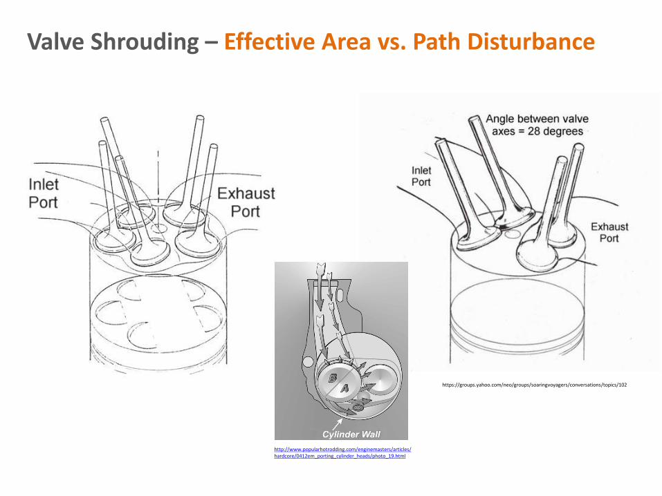
Valve Shrouding – Effective Area vs. Path Disturbance
http://www.popularhotrodding.com/enginemasters/articles/hardcore/0412em_porting_cylinder_heads/photo_19.html

Valve Shrouding – Trajectory Nozzles
http://www.google.com/patents/US7398748
http://www.google.com/patents/US4355604
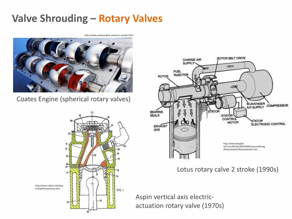
Valve Shrouding – Rotary Valves http://www.coatesengine.com/csrv-system.html
Coates Engine (spherical rotary valves)
http://www.douglas-self.com/MUSEUM/POWER/unusualICeng/RotaryValveIC/RotaryValveIC.htm
Lotus rotary calve 2 stroke (1990s)
http://www.villiers.info/Aspin/AspinEssay/essay.htm
Aspin vertical axis electric-actuation rotary valve (1970s)

http://www.clubgti.com/showthread.php?265529-F1-Cylinder-Head-Construction-and-Pneumatics-a-closer-look
Honda V8 F1 engine (18 k rev/min) sectioned cylinder head (mean piston speed at 18 k rev/min = 24.8 m/s); Vchamber = 300 cm3; bore/stroke = 2.3; rod/stroke = 2.7
Valve Shrouding – Effective Area vs. Path Disturbance
http://www.racecar-engineering.com/articles/f1/hondas-f1-engine-revealed/#.UpSFWpv8uUS.twitter
Honda V10 F1 engine (15 k rev/min), dual plane valve inclination (reduced bore shrouding), pneumatic valve actuation

http://www.taringa.net/posts/autos-motos/1119657/El-Motor-Desmodromico.html
Valve Motion – Positive Valve Closing Mechanisms

Air Admission – Air Injector Concept
Injector: Denso Fan / Denso 10 Hole Alphabet / Bosch C270 (70° cone) / Bosch HDEV4 (Piezo, 200 bar, ≈ 40 cm3/s)
• Injector: Bosch HDEV 4/4.1 Hollow Cone; DI piezoelectric; 140 to 200 bar fuel pressure
• High flow rate (fuel) ≈ 42 mg/ms @ 200 bar (277 mg for 6.6 ms or 20 CA @500 rev/min)
• Multiple injection

?
Air motion ‘look-see’ study
Quiescent environment; seeded air (powder suspended in chamber a priori of injection)
Spray chamber (MK1)
Air Admission – F-Air Injector (chamber experiments)
Hollow Cone DI

1 2
1 – Cross-flow
2 – Injection flow
Duct Injector
Experiments informed by research engine engine specifications:
• 80 mm duct section (74 mm bore)
• Mean bulk air motion associated with 500 rev/min
(Tiago Carvalho, Dr de Sercey)
Particle Image Velicimetry (PIV) study of injection into a crossflow. Part of feasability study for using an fuel injector as an air injector (F-Air Injector)
Air Admission – F-Air Injector (crossflow experiments)

Results at 4 bar and -500 μs ASOI (static crossflow):
Air Admission – F-Air Injector (crossflow experiments)

• Experiments were carried out with 4 different image measurement times, After Start of Injection (ASOI) and 4 different cross-flow speeds
• Images were post-processed using the Adaptive PIV method
Air Admission – F-Air Injector (crossflow experiments)
Results for injection into crossflow (event sequence)

2 m/s 5 m/s 7 m/s 10 m/s
• Display options set to show U and V components of the flow velocity
• The U (horizontal) component is displayed with a contour plot
• The V (vertical) component is displayed with vertical blue vectors
Air Admission – F-Air Injector (crossflow experiments)
Results for injection into crossflow (increasing crossflow velocity)

In-cylinder air motion for the promotion of rapid combustion
Primary motion Combustion chamber layout Mixture preparation

http://www.avtonline.co.uk/theworkshop/theworkshop/tumbleflapsandswirlflaps#.Ud04HPm1Fhw
Swirl Dominated Motion
Tumble Dominated Motion
http://fr.wikipedia.org/wiki/Piston_(m%C3%A9canique)#mediaviewer/File:Swirl_and_Tumble.svg
In-Cylinder Air Motion – Primary Motion

Chrysler twin spark semi-hemi (in production)
http://www.automobilemag.com/features/news/0407_hemi_engine/
M-B 113 (2000s)
In-Cylinder Air Motion – Chamber Layout
http://russellengineering.com.au/tag/mini/
http://www.fitzhughmedia.com/MBF/W208-3.html
ALFA Romeo hemi; 10° CA ignition advance reduction (1990s)
Austin A-series (1990s)

https://www.highpowermedia.com/blog/3359/directly-so
In-Cylinder Air Motion – DI Gasoline
Wall guided Spray guided
http://www.kidston.com/kidston-cars/31/1956-Mercedes-Benz-300SL
High fuel pressure (up to 200 bar) for rapid atomisation / evaporation
Reduced penetration (multiple fuel injections, 0.1 to 3 ms injection duration)
In-cylinder gas absolute pressure at injection up to 40 bar

http://www.full-race.com/articles/inside-the-ecoboost-f-150.html
In-Cylinder Air Motion – DI Gasoline (Ford Ecoboost)
Typical leading edge technology for production SI engines

In-Cylinder Air Motion – Disruptive Technology?
http://www.spherelab.gatech.edu/
• Traditional high speed SI engines suggest ‘multi’ input hardware (fuel; spark; air)
• With the combustor of the split-cycle engine, we retain a fundamental chemistry governed flame speed / combustion time requirement, AND, lose the air motion contribution of the piston, which is a significant source of mixing inducing tumble motion. These both present challenges to rapid combustion
• What next?

‘Strato-geneous’ (Vector Guided F-Air Injection)
Multiple stratified combustion fields are ignited ‘simultaneously’ to mitigate the time required for flame front propagation
Air Inlet
In-Cylinder Air Motion – Concepts
Fuel Inlet
Central / peripheral squish regions
CEREEV proof of concept combustor machine Experimental facility Proof of concept(s) combustor machine
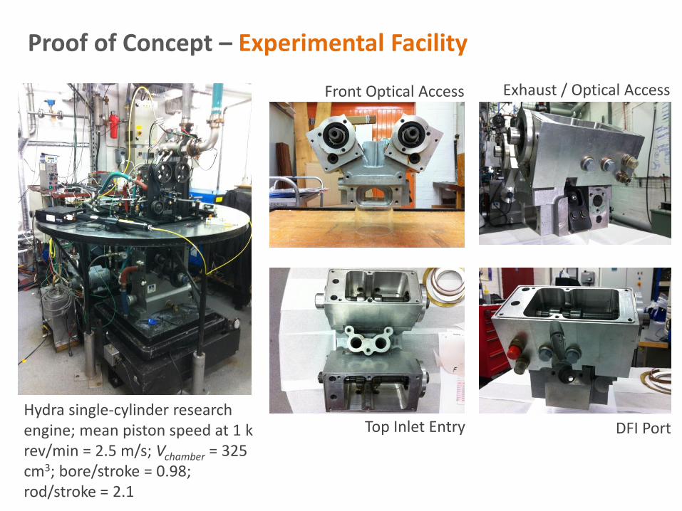
Front Optical Access
DFI Port Top Inlet Entry
Exhaust / Optical Access
Hydra single-cylinder research engine; mean piston speed at 1 k rev/min = 2.5 m/s; Vchamber = 325 cm3; bore/stroke = 0.98; rod/stroke = 2.1
Proof of Concept – Experimental Facility
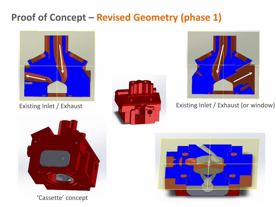
Proof of Concept – Revised Geometry (phase 1)
Existing Inlet / Exhaust Existing Inlet / Exhaust (or window)
‘Cassette’ concept

Spark plug
Fuel injector
Piston
• Concept chamber and piston design for maximum compression (expansion) ratio • Pre-chamber two stage combustion process
Proof of Concept – MPP Head

Prototype cylinder head and twin air injector assembly
• Design of injection ports air and fuel, piston crown, spark plug pocket • Integration of standard or low lift camshafts in addition to EHV • Exhaust manifold • In-cylinder pressure transducer recess
Proof of Concept – MPP Head

• Concept piston crown with piston crown pre-chamber for two-stage combustion
Proof of Concept – MPP Head
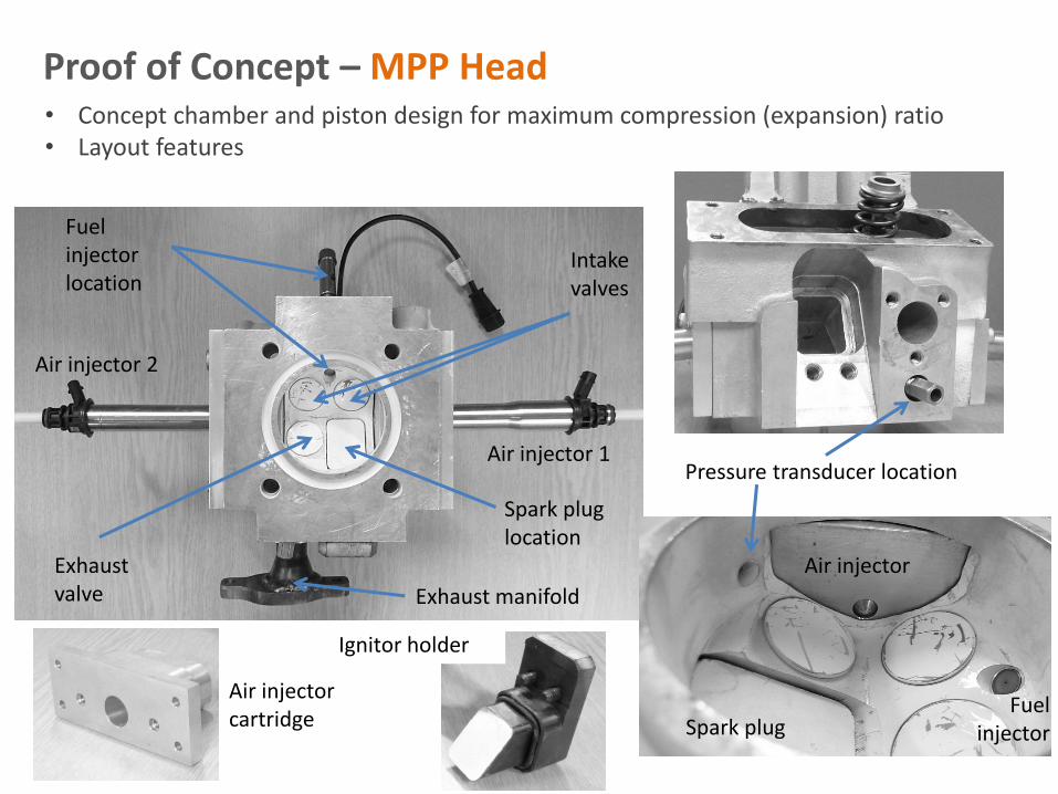
• Concept chamber and piston design for maximum compression (expansion) ratio • Layout features
Spark plug location
Fuel injector location
Exhaust manifold
Exhaust valve
Air injector 1
Intake valves
Air injector 2
Pressure transducer location
Ignitor holder
Air injector cartridge
Air injector
Fuel injector Spark plug
Proof of Concept – MPP Head

Prototype engine kit / Ensemble de la concept !
Proof of Concept – MPP Head

The University of Brighton team, circa 2014
Thank you – Merci Beaucoup!