Embed Size (px)
Citation preview
Bukit Panjang Bus Interchange
Page 1 of 72
Appendix G to Schedule 1
LAND TRANSPORT AUTHORITY
Mechanical & Electrical (M & E) Design Criteria
For Bus Interchange
Appendix G - 2
Bukit Panjang Bus Interchange
Page 2 of 72
CONTENTS
1 INTRODUCTION ........................................................................................................................ 6 1.1 General ................................................................................................................................ 6 1.2 Acronyms and Definitions .................................................................................................... 6 1.3 Related Design Standard, Codes And Regulations ............................................................ 6 1.4 Submission Procedure......................................................................................................... 7
1.4.1 Pre-Submission Consultation ....................................................................................... 7 1.4.2 Design Submission ....................................................................................................... 7 1.4.3 Amendment Submission .............................................................................................. 7 1.4.4 Completion Of Works ................................................................................................... 8 1.4.5 As-Built Documentation Submission ............................................................................ 8
2 DESIGN OBJECTIVES ............................................................................................................... 9 3 GUIDELINES ON BUS INTERCHANGE .................................................................................. 10
3.1 Design Criteria by Area ..................................................................................................... 10 3.1.1 Concourse Area.......................................................................................................... 10 3.1.2 Bus Parking Area / Driveway / Alighting Bay ............................................................. 10 3.1.3 Passenger Service Office ........................................................................................... 11 3.1.4 Administration Office .................................................................................................. 11 3.1.5 Staff Lounge ............................................................................................................... 12 3.1.6 Canteen / Snack Corner ............................................................................................. 12 3.1.7 Store Room (Rodent-Free) ......................................................................................... 12 3.1.8 Kitchen/Food Preparation Area .................................................................................. 12 3.1.9 Technician's Room ..................................................................................................... 13 3.1.10 Ticket Office (TO) ....................................................................................................... 13 3.1.11 AVM Room ................................................................................................................. 14 3.1.12 Store Room ................................................................. Error! Bookmark not defined. 3.1.13 Cleaner's Room .......................................................................................................... 14 3.1.14 Systems Room ........................................................................................................... 14 3.1.15 Toilet Facilities ............................................................................................................ 14 3.1.16 Other Facilities............................................................................................................ 15
3.2 Lighting Requirement For Bus Interchange ....................................................................... 17 3.3 Lightning Protection System .............................................................................................. 17 3.4 Earthing System And Equipotential Bonding ..................................................................... 17 3.5 Water Services, Sanitary Works And Pumped Drainage System ..................................... 17
3.5.1 Water Services ........................................................................................................... 17 3.5.2 Sanitary Works System .............................................................................................. 18 3.5.3 Pumped Drainage System ......................................................................................... 18
3.6 Passenger Lift (where applicable) ..................................................................................... 18 3.6.1 Design Requirements ................................................................................................. 18
3.7 Escalator (where applicable) ............................................................................................. 18 3.7.1 Design Requirement ................................................................................................... 18 3.7.2 Automatic Starting And Stopping Operation .............................................................. 18
3.8 Air-Conditioning and Mechanical Ventilation System ........................................................ 18 3.8.1 General ....................................................................................................................... 18 3.8.2 Ventilation for Covered Bus Parking Area, Driveway and Alighting Bay ................... 19
3.9 Equipment Noise Control ................................................................................................... 20 3.10 Fire Protection System In Bus Interchange ....................................................................... 21
3.10.1 Automatic Fire Alarm System ..................................................................................... 21 3.10.2 Automatic Fire Sprinkler System ................................................................................ 21 3.10.3 Fire Hydrant System ................................................................................................... 21 3.10.4 Dry Rising Main .......................................................................................................... 21
Appendix G - 3
Bukit Panjang Bus Interchange
Page 3 of 72
3.10.5 Fire Hosereel System ................................................................................................. 21 3.10.6 Fire Extinguishers ....................................................................................................... 21
3.11 Building Management System ........................................................................................... 21 4 TECHNICAL SPECIFICATIONS .............................................................................................. 22
4.1 Code And Regulation......................................................................................................... 22 4.2 LV Power Systems ............................................................................................................ 22
4.2.1 LV Main Switchboard ................................................................................................. 22 4.2.2 LV Distribution Board (DB) ......................................................................................... 24 4.2.3 Overground (OG) Box ................................................................................................ 25 4.2.4 Switchgear, Apparatus And Internal Wiring ............................................................... 25 4.2.5 LV Cables ................................................................................................................... 26 4.2.6 Ancillary Equipment .................................................................................................... 27
4.3 Lighting Fixtures And Installation ....................................................................................... 27 4.3.1 General ....................................................................................................................... 27 4.3.2 Types of Lamps .......................................................................................................... 28 4.3.3 Types of Light Fixtures ............................................................................................... 29
4.4 Lightning Protection System .............................................................................................. 30 4.4.1 General ....................................................................................................................... 30 4.4.2 Air Terminations ......................................................................................................... 30 4.4.3 Down Conductors ....................................................................................................... 31 4.4.4 Joints and Bonds ........................................................................................................ 31 4.4.5 Earth Termination ....................................................................................................... 31
4.5 Cable Support Systems ..................................................................................................... 31 4.5.1 General ....................................................................................................................... 31 4.5.2 Metal Trunking and Accessories ................................................................................ 31 4.5.3 Galvanised Iron Conduits and Accessories ............................................................... 31 4.5.4 Flexible Conduits ........................................................................................................ 32 4.5.5 UPVC Conduit/Pipe and Accessories ........................................................................ 32 4.5.6 Cable Tray and Accessories ...................................................................................... 32
4.6 Earthing System And Equipotential Bonding ..................................................................... 32 4.6.1 General ....................................................................................................................... 32 4.6.2 Earth Termination ....................................................................................................... 32
4.7 Water Services, Sanitary Works And Pumped Drainage System ..................................... 33 4.7.1 Pipe work .................................................................................................................... 33 4.7.2 Sewage Ejector Pumping System .............................................................................. 33 4.7.3 Pumped Drainage System ......................................................................................... 33 4.7.4 Motor Control Panel ................................................................................................... 33 4.7.5 Motor Starter And Motor ............................................................................................. 34 4.7.6 Special Requirement For Motor Of Sump Pumps ...................................................... 34
4.8 Passenger Lift .................................................................................................................... 35 4.8.1 Design Requirements ................................................................................................. 35 4.8.2 Safety Requirements .................................................................................................. 36 4.8.3 Cable Requirements ................................................................................................... 38 4.8.4 Provisions For People With Special Needs ................................................................ 38 4.8.5 Lift Inter-Communication System ............................................................................... 38
4.9 Escalators .......................................................................................................................... 39 4.9.1 Design Requirement ................................................................................................... 39 4.9.2 Energy Conservation Requirements .......................................................................... 40 4.9.3 Machine Rooms/Pits And Closets .............................................................................. 41 4.9.4 Cable Requirements ................................................................................................... 41 4.9.5 Safety Requirements .................................................................................................. 41 4.9.6 Corrosion Resistance And Material Requirements .................................................... 42
4.10 Air-Conditioning And Mechanical Ventilation System ....................................................... 42
Appendix G - 4
Bukit Panjang Bus Interchange
Page 4 of 72
4.10.1 Pipe works .................................................................................................................. 42 4.10.2 Sheet Metal Ductwork and Accessories ..................................................................... 42 4.10.3 Ductwork Insulation .................................................................................................... 42 4.10.4 Pipe work Insulation ................................................................................................... 42 4.10.5 Air Filters .................................................................................................................... 43 4.10.6 Air Curtain ................................................................................................................... 43
4.11 Fire Sprinkler System ........................................................................................................ 43 4.11.1 Sprinkler Heads .......................................................................................................... 43 4.11.2 Sprinkler Control Valve Set, Electrically Supervised Gate Valve and Accessories ... 44 4.11.3 Alarm Gong ................................................................................................................ 44 4.11.4 Pressure Switches ...................................................................................................... 44 4.11.5 Flow Switches............................................................................................................. 44 4.11.6 Pressure Gauges ....................................................................................................... 44 4.11.7 Flow Meter .................................................................................................................. 45 4.11.8 Sprinkler Tank ............................................................................................................ 45 4.11.9 Sprinkler Breeching Inlets .......................................................................................... 46 4.11.10 Pumps ..................................................................................................................... 46 4.11.11 Fire Pump Control Panel ........................................................................................ 47 4.11.12 Miscellaneous ......................................................................................................... 50 4.11.13 Pump Controls ........................................................................................................ 51
4.12 Analogue Addressable Automatic Fire Alarm System ....................................................... 51 4.12.1 General ....................................................................................................................... 51 4.12.2 Operational Requirement ........................................................................................... 51 4.12.3 Main Alarm Panel ....................................................................................................... 51 4.12.4 Fire Alarm Bell ............................................................................................................ 53 4.12.5 Manual Call Point ....................................................................................................... 54
4.13 Fire Hosereel & Hydrant System ....................................................................................... 54 4.13.1 General ....................................................................................................................... 54 4.13.2 Hosereel System ........................................................................................................ 54 4.13.3 Hydrant System .......................................................................................................... 55 4.13.4 Water Supply .............................................................................................................. 55 4.13.5 Piping and Installation ................................................................................................ 55
4.14 Portable Fire Extinguishers ............................................................................................... 55 4.14.1 General ....................................................................................................................... 55 4.14.2 Installation .................................................................................................................. 55
4.15 Pipework ............................................................................................................................ 56 4.15.1 General ....................................................................................................................... 56 4.15.2 Piping Installation ....................................................................................................... 56 4.15.3 Installation of Pipe Hangers and Supports ................................................................. 57 4.15.4 Protection of Pipeworks .............................................................................................. 57 4.15.5 Pipework Materials ..................................................................................................... 57 4.15.6 Pipe Joints .................................................................................................................. 57 4.15.7 Pipe Fittings ................................................................................................................ 58 4.15.8 Gaskets ...................................................................................................................... 58 4.15.9 Vertical and Riser Pipe Isolation ................................................................................ 58 4.15.10 Horizontal Pipe Isolation ......................................................................................... 58 4.15.11 Sleeves and Covers ................................................................................................ 58 4.15.12 Stainless Steel Bellow Expansion Joints ................................................................ 59 4.15.13 Pipe Anchors........................................................................................................... 59 4.15.14 Valves, Cocks etc. .................................................................................................. 59 4.15.15 Cleaning Procedure ............................................................................................... 60
4.16 Surface Treatment ............................................................................................................. 60 4.16.1 Corrosion Protection ................................................................................................... 60
Appendix G - 5
Bukit Panjang Bus Interchange
Page 5 of 72
4.16.2 Metal ........................................................................................................................... 60 4.16.3 Non-Metallic Materials ................................................................................................ 60 4.16.4 Bolts, Screws, Nuts .................................................................................................... 60 4.16.5 Painting ....................................................................................................................... 61
5 APPENDIX 1 ............................................................................................................................. 62 5.1 Typical Control and Monitoring Point Schedule for Building Management System .......... 62
Appendix G - 6
Bukit Panjang Bus Interchange
Page 6 of 72
1 INTRODUCTION
1.1 General
This document, which is also called the Mechanical and Electrical Design Criteria for Bus Interchange, (MEDC BI) defines the criteria and requirements of the Electrical and Mechanical (E&M) system for the design, construction, testing and commissioning of the Electrical and Mechanical (E&M) systems for the Bus Interchange.
It is the responsibility of the designer to highlight to the Authority any contradiction or conflicts within the criteria set out hereafter. In addition, the designer shall notify and seek the Authority’s acceptance to any change or new requirements that may arise during the use of the part or whole of the criteria.
1.2 Acronyms and Definitions
Mains - Incoming Electricity supply.
Lighting point - A termination of a fixed wiring system intended for the attachment
of a luminaire.
Illuminance - The luminous flux density at a surface, i.e. the luminous flux incident
Per unit area.
The unit of illuminance is lux.
Luminare - Apparatus, which distributes, filters and transforms the light given by a lamp or lamps and which includes all the items necessary for fixing and protecting these lamps and for connecting them to the supply circuit.
Mounting Height - The vertical distance between a luminaire and the working plane.
Emergency Lighting - Lighting provided for use when the supply to the normal lighting fails.
Exit Light - The part of emergency lighting, which provide to luminaire the exits.
Uniformity Ratio - The ratio of the minimum illuminance to the average illuminance applied to the values on the working plane.
Colour rendering - A general expression for the appearance of colours when illuminated by light form a given source compared, consciously or unconsciously with their appearance under light from some reference source.
Colour temperature - The temperature of a full radiator, which emits radiation of the same chromaticity as the radiator considered. (The unit is Kelvin)
Glare - The discomfort or impairment of vision experienced when parts of the visual field are excessively bright in relation to the general surrounding.
Equipotential Bonding - Electrical connection maintaining various exposed-conductive-parts and extraneous conductive parts at substantially the same potential.
Ventilation The process of supplying or removing air, by neutral or mechanical means, to or from any space. Such air may or may not have been conditioned.
Air Changes - A method of expressing the rate of air entering or leaving a space by natural or mechanical means in terms of the number of volumes of the spaces.
Air-Conditioning - The process of treating air so as to control simultaneously its temperature, humidity, cleanliness and distribution to met the requirements of the conditioned space.
FMS - Facilities Management System
PUP- Pedestrian Underpass
Contractor - Contractor or Designer
1.3 Related Design Standard, Codes And Regulations
Unless otherwise stated, the mechanical and electrical works for bus interchange shall be governed by all applicable local regulations, codes, standards and requirements issued by all relevant authorities having jurisdiction, which shall include but not limited to the following:
- Singapore Public Utility Board (PUB)
Appendix G - 7
Bukit Panjang Bus Interchange
Page 7 of 72
- Fire Safety and Shelter Department (FSSD)
- Building Control Authority (BCA)
- Ministry of the Environment and Water Resources
- National Environment Agency (NEA)
- National Parks Boards (Nparks)
- Energy Marketing Authority (EMA)
- Productivity and Standards Board (PSB)
- Land Transport Authority (LTA)
Where there are discrepancies or conflicts between the above, the Contractor shall bring them to the attention of the Authority for final decision. Compliance with the EMDC BI criteria shall not preclude the Contractor from having to obtain full clearance and approval from the Development and Building Control Department (DBC), LTA and all authorities having jurisdiction.
1.4 Submission Procedure
1.4.1 Pre-Submission Consultation The Contractor shall preconsult the relevant authorities having jurisdiction such as Nparks, PUB, Power Grid Ltd, Power Supply Ltd, LTA, etc before embarking on the design of the bus interchange to avoid unnecessary abortive work.
1.4.2 Design Submission The Contractor shall submit two (2) sets of the documents listed below, in the appropriate format, when seeking approval from the Authority and prior to commencement of works.
All drawings and calculations shall be certified by the Qualified Person (QP).
No works shall commence until approval of the subject design and relevant waiver is obtained from the Authority in writing.
1.4.2.1 General :
- Site and location plan showing the source of the incoming supply and indicate the area that is to be hand-over to LTA.
1.4.2.2 Electrical Installations:
- Single line diagrams for the electrical installation to the bus interchange.
- Lighting and power layout plans including cable routing plans.
- Earthing system schematics and layout plans.
- Catalogues with all relevant test certificates to demonstrate compliance for the equipment specified and technical specifications for the equipment to be installed.
- All electrical calculations to substantiate selection of plant and equipment. It shall include circuit breaker and cable sizing, fault level calculations, discrimination setting between various breakers and etc
- Lighting design calculations to substantiate that the design is in accordance to the lighting requirements as set out in the design criteria.
- Lightning Protection System shall design in accordance to the latest edition Code of Practice, CP 33.
1.4.2.3 Mechanical Installations
- Air-conditioning and Mechanical Ventilation System Design
- Fire Protection System Design
- Water Services, Sanitary Works and Pumped Drainage Design
- All services routing, installation detail and sizes
- Properly dimensioned layout diagrams showing the location of equipment
- Equipment installation details
- Automatic control and monitoring philosophy.
- Calculations including cooling load calculation, mechanical ventilation calculations, pump capacity sizing, operating pumping head and pump operating levels (start/stop, alarm level, etc), fan pressure calculations, cable sizing, voltage drop calculations, motor starter capacity, sprinkler hydraulic calculation, etc.
- Calculations on the mounting, inertia blocks vibration isolations and noise controls.
- Structural equipment bases, supports and tank details
- Catalogues and technical specifications for the equipment, materials and accessories
1.4.3 Amendment Submission The Contractor shall notify the Authority of any deviations from the approved plans and submit the revised plans to the Authority for approval before any deviation works commenced
Appendix G - 8
Bukit Panjang Bus Interchange
Page 8 of 72
1.4.4 Completion Of Works
1.4.4.1 Testing And Commissioning And Hand-over To The Authority
Upon completion of the mechanical and electrical works, the Contractor shall perform visual inspections and all necessary testing and commissioning of the works. The test results which shall be endorsed by the QP shall be submitted to the Authority for acceptance. Instruments used for the tests shall have a valid calibration certificate. The calibration certificates shall be submitted together with the test results. The tests to be conducted shall include but not limited to the following:
1) Site Lux Level Measurement Test Results for Lighting System.
2) Electrical System Tests
- Insulation voltage test with appropriate insulation tester
- Earth loop impedance test
- Continuity test on the conductor & joints
- Polarity and phase sequence
3) Earth Resistance Test Results for Lightning Protection System
4) Mechanical Systems Test
- Individual Equipment and System Performance Tests
- Air flow and Balancing Test
- Hydraulic Test
- Pump Test
- Operation and Control Function Tests
- Interface Tests with Other Systems
- Noise Level Measurement
The Contractor shall give the Authority at least 7 days advanced notice of any joint inspection or tests. The Contractor shall rectify all defects identified during the joint inspections and a final joint inspection to certify the clearance of all defects shall be arranged.
1.4.5 As-Built Documentation Submission Two (2) sets of the as-built drawings, testing and commissioning results endorsed by the QP and operation and maintenance (O&M) manuals for the electrical and mechanical installations, shall be submitted to the Authority, prior to handling over of the bus interchange to the Authority. These shall include but not limited to the following:
1.4.5.1 Electrical Installations
- As-built electrical single line diagrams
- Lighting and power layout plans
- Earthing system schematics and layout plans
- Lightning protection system layout plans.
- Testing and commissioning results of the lighting level and electrical installation
- Testing and commissioning results of the Lightning Protection System and certificate of supervision for Lightning Protection System duly endorsed by Electrical Professional Engineer(P.E) is in accordance to the latest edition of Code of Practices, CP 33.
1.4.5.2 Mechanical Installations
- As-built mechanical services plan
- Testing and commissioning results of the mechanical services and related electrical installation
- Approved plans to authorities
Appendix G - 9
Bukit Panjang Bus Interchange
Page 9 of 72
2 DESIGN OBJECTIVES
The Authority has determined a set of design objectives for the bus interchange which the Contractor is required to comply. These objectives do not exclude any additional design standards or criteria that may be required to suit the needs of the particular locations.
Appendix G - 10
Bukit Panjang Bus Interchange
Page 10 of 72
3 GUIDELINES ON BUS INTERCHANGE
3.1 Design Criteria by Area
The following list indicates the M&E services requirements for the various areas of the bus interchange.
3.1.1 Concourse Area
a Lighting Minimum 150 lux measured at floor level with uniformity ratio of 0.3. Means of varying the lighting level via timer relay control to achieve 33%, 66% and 100 % lighting level shall be provided in the design.
b Emergency / Battery back-up lighting 2hrs for evacuation
As per SS CP 19.
c Emergency Lighting System; 6 hours for continuous operation
Average of 20 lux for 6 hours
d Signage, information board & advertising panel
13A Fused Connection Unit with male /female adapter to be located within each lighted sign / information board / advertising panel.
e Public Telephone Points Minimum 4 nos. with power points and telephone points. As per latest IDA guidelines.
f General power points
- For elevated bus interchange, 13A flush type switch socket outlet (SSO) within a weatherproof lockable metal cabinets shall be provided and mounted at 1.4m height at each boarding location.
- For integrated bus interchange, 13A flush type (SSO) shall be provided and mounted at 1.4m height at each boarding location.
- 1 no. 13A SSO will be provided near each EIDS (Electronic Information Display System) and controlled by a fused switch at the PSO.
Note: All general purpose power points shall be protected by residual current circuit breaker (RCCB).
g
Water Services Tap points shall be provided and enclosed by stainless steel casing with pad lock for elevated bus interchange only.
h Sanitary Works Floor wastes/trap shall be provided i Mode of ventilation
# Air-conditioning for integrated bus interchange
For the design of the air-conditioning system, the following shall be assumed: i) Number of occupants : 3 m²/person (for Circulation area) & 1
m²/person (for Queuing area) ii) Fresh Air Supply: 1.2 L/s per m² floor area
* Natural Ventilation for elevated bus interchange j Automated Screen Doors Automated screen doors (ASD) to be equipped with auto-lock
mechanism when powered down locally at each individual screen doors during non-operation hours shall be provided. Alternative means of powering down each ASD shall be provided at the PSO office for remote control by the operator.
3.1.2 Bus Parking Area / Driveway / Alighting Bay
a Lighting
Covered - Entrance/Exit – 100/50 lux (day/night) measured at floor level
with a uniformity of 0.3. - Ramps and Corners - 75 / 50 lux (day/night) measured at
floor level with a uniformity of 0.3. - Bus Park - 50 / 20 lux (day/night) measured at floor level with
a uniformity of 0.3. Non- Covered - Entrance/Exit - 20 lux measured at floor level with a uniformity
of 0.3.
Appendix G - 11
Bukit Panjang Bus Interchange
Page 11 of 72
- Ramps and Corners 50 lux measured at floor level with a
uniformity of 0.3. - Bus Park - 15 lux measured at floor level with a uniformity of
0.3. (Detailed design should be in accordance to CP 38 requirements).
b Emergency power for lightings; (For integrated Bus interchange only).
Emergency lighting system by Gen Set and UPS (10mins) for continuous power supply during the interval between PG power failure and the generator.
c Loop Detector Associated power supply provisions for loop detectors to be provided for the operation of auto-doors within the Integrated Bus Interchange.
d General power points
- 13A flush type switch socket outlet (SSO) within a weatherproof lockable metal cabinets shall be provided and mounted at 1.4m height.
- Note: All general purpose power points shall be protected by residual current circuit breaker (RCCB).
e Water Services
Tap points shall be provided and enclosed by stainless steel casing with pad lock.
f Sanitary Works
To provide according to relevant code requirement.
g Mode of Ventilation
Non-Covered Natural ventilation Covered Natural / Mechanical Ventilation as described in Section 3.8.
3.1.3 Passenger Service Office
a Lighting - Lighting level as per SS 531.
b Emergency / Battery back-up lighting 2hrs
As per SS CP 19.
c Mode of Ventilation Air-conditioning a) Air-cooled split fan coil unit for elevated bus interchange. b) Chilled water fan coil unit for integrated bus interchange.
d Power Points for equipment
Minimum 26 nos. 13A switch socket outlets mounted at 300mm height from FFL to be distributed evenly throughout the Passenger Service Office.
e Telephone / communication point / outlet
- Minimum 4 nos. to be located at each wall of the Passenger Service Office mounted at 300mm height from FFL.
- Conduits/Trunkings with draw wire only will be provided for computer cables.
f Sanitary Works Floor waste/trap for connection of the air-conditioning drain shall be provided.
g Others
Passenger Service Office shall be provided with individual distribution board located within the office. All electrical circuits within the office shall originate from this distribution board. BMS operator workstation shall be installed in this room.
3.1.4 Administration Office
a Lighting - Lighting level as per SS 531.
b Emergency / Battery back-up lighting 2hrs
As per SS CP 19.
c Mode of Ventilation
Air-conditioning a) Air-cooled split fan coil unit for elevated bus interchange. b) Chilled water fan coil unit for integrated bus interchange.
- d Power Points for
equipment
Minimum 8 nos. 13A switch socket outlets shall be provided, mounted at 300mm height from FFL, and distributed evenly throughout the office.
e Telephone / communication point / outlet
Minimum 3 nos shall be provided, mounted at 300mm height from FFL and distributed evenly throughout the office Conduits/Trunkings with draw wire only will be provided for computer cables.
Appendix G - 12
Bukit Panjang Bus Interchange
Page 12 of 72
f Sanitary Works Floor waste/trap for connection to condensate drainage pipes from the air-conditioning units.
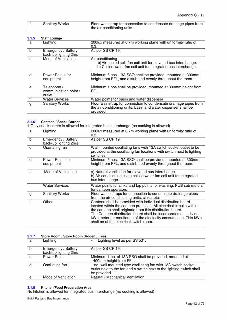
3.1.5 Staff Lounge
a Lighting 200lux measured at 0.7m working plane with uniformity ratio of 0.3.
b Emergency / Battery back-up lighting 2hrs
As per SS CP 19.
c Mode of Ventilation
Air-conditioning b) Air-cooled split fan coil unit for elevated bus interchange. b) Chilled water fan coil unit for integrated bus interchange.
- d Power Points for
equipment
Minimum 6 nos. 13A SSO shall be provided, mounted at 300mm height from FFL, and distributed evenly throughout the room.
e Telephone / communication point / outlet
Minimum 1 nos shall be provided, mounted at 300mm height from FFL.
f Water Services Water points for basin and water dispenser g Sanitary Works Floor waste/trap for connection to condensate drainage pipes from
the air-conditioning units, basin and water dispenser shall be provided.
3.1.6 Canteen / Snack Corner # Only snack corner is allowed for integrated bus interchange (no cooking is allowed)
a Lighting 200lux measured at 0.7m working plane with uniformity ratio of 0.3.
b Emergency / Battery back-up lighting 2hrs
As per SS CP 19.
c Oscillating fan
Wall mounted oscillating fans with 13A switch socket outlet to be provided at the oscillating fan locations with switch next to lighting switches.
d Power Points for equipment
Minimum 5 nos. 13A SSO shall be provided, mounted at 300mm height from FFL, and distributed evenly throughout the room.
e Mode of Ventilation
a) Natural ventilation for elevated bus interchange. b) Air-conditioning using chilled water fan coil unit for integrated bus interchange..
f Water Services Water points for sinks and tap points for washing. PUB sub meters for canteen operators
g Sanitary Works
Floor wastes/traps for connection to condensate drainage pipes from the air-conditioning units, sinks, etc.
i Others
Canteen shall be provided with individual distribution board located within the canteen premises. All electrical circuits within the canteen shall originate from this distribution board. The Canteen distribution board shall be incorporates an individual kWh meter for monitoring of the electricity consumption. This kWh shall be at the electrical switch room.
3.1.7 Store Room / Store Room (Rodent Free)
a Lighting - Lighting level as per SS 531.
b Emergency / Battery back-up lighting 2hrs
As per SS CP 19.
c Power Point Minimum 1 no. of 13A SSO shall be provided, mounted at 1400mm height from FFL.
d Oscillating fan 1 no. wall mounted type oscillating fan with 13A switch socket outlet next to the fan and a switch next to the lighting switch shall be provided.
e Mode of Ventilation Natural / Mechanical Ventilation
3.1.8 Kitchen/Food Preparation Area No kitchen is allowed for integrated bus interchange (no cooking is allowed)
Appendix G - 13
Bukit Panjang Bus Interchange
Page 13 of 72
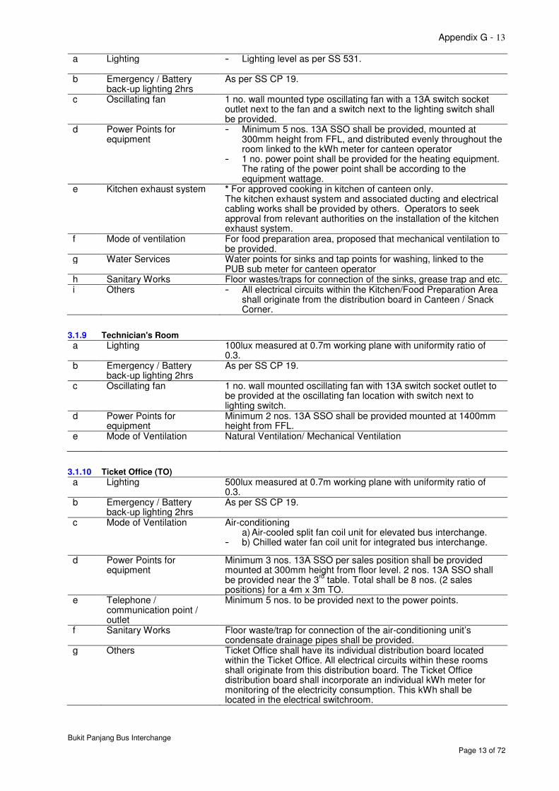
a Lighting - Lighting level as per SS 531.
b Emergency / Battery back-up lighting 2hrs
As per SS CP 19.
c Oscillating fan
1 no. wall mounted type oscillating fan with a 13A switch socket outlet next to the fan and a switch next to the lighting switch shall be provided.
d Power Points for equipment
- Minimum 5 nos. 13A SSO shall be provided, mounted at 300mm height from FFL, and distributed evenly throughout the room linked to the kWh meter for canteen operator
- 1 no. power point shall be provided for the heating equipment. The rating of the power point shall be according to the equipment wattage.
e Kitchen exhaust system * For approved cooking in kitchen of canteen only. The kitchen exhaust system and associated ducting and electrical cabling works shall be provided by others. Operators to seek approval from relevant authorities on the installation of the kitchen exhaust system.
f Mode of ventilation For food preparation area, proposed that mechanical ventilation to be provided.
g Water Services Water points for sinks and tap points for washing, linked to the PUB sub meter for canteen operator
h Sanitary Works Floor wastes/traps for connection of the sinks, grease trap and etc. i Others
- All electrical circuits within the Kitchen/Food Preparation Area
shall originate from the distribution board in Canteen / Snack Corner.
3.1.9 Technician's Room
a Lighting 100lux measured at 0.7m working plane with uniformity ratio of 0.3.
b Emergency / Battery back-up lighting 2hrs
As per SS CP 19.
c Oscillating fan
1 no. wall mounted oscillating fan with 13A switch socket outlet to be provided at the oscillating fan location with switch next to lighting switch.
d Power Points for equipment
Minimum 2 nos. 13A SSO shall be provided mounted at 1400mm height from FFL.
e Mode of Ventilation
Natural Ventilation/ Mechanical Ventilation
3.1.10 Ticket Office (TO)
a Lighting 500lux measured at 0.7m working plane with uniformity ratio of 0.3.
b Emergency / Battery back-up lighting 2hrs
As per SS CP 19.
c Mode of Ventilation
Air-conditioning a) Air-cooled split fan coil unit for elevated bus interchange.
- b) Chilled water fan coil unit for integrated bus interchange.
d Power Points for equipment
Minimum 3 nos. 13A SSO per sales position shall be provided mounted at 300mm height from floor level. 2 nos. 13A SSO shall be provided near the 3
rd table. Total shall be 8 nos. (2 sales
positions) for a 4m x 3m TO. e Telephone /
communication point / outlet
Minimum 5 nos. to be provided next to the power points.
f Sanitary Works
Floor waste/trap for connection of the air-conditioning unit’s condensate drainage pipes shall be provided.
g Others Ticket Office shall have its individual distribution board located within the Ticket Office. All electrical circuits within these rooms shall originate from this distribution board. The Ticket Office distribution board shall incorporate an individual kWh meter for monitoring of the electricity consumption. This kWh shall be located in the electrical switchroom.
Appendix G - 14
Bukit Panjang Bus Interchange
Page 14 of 72
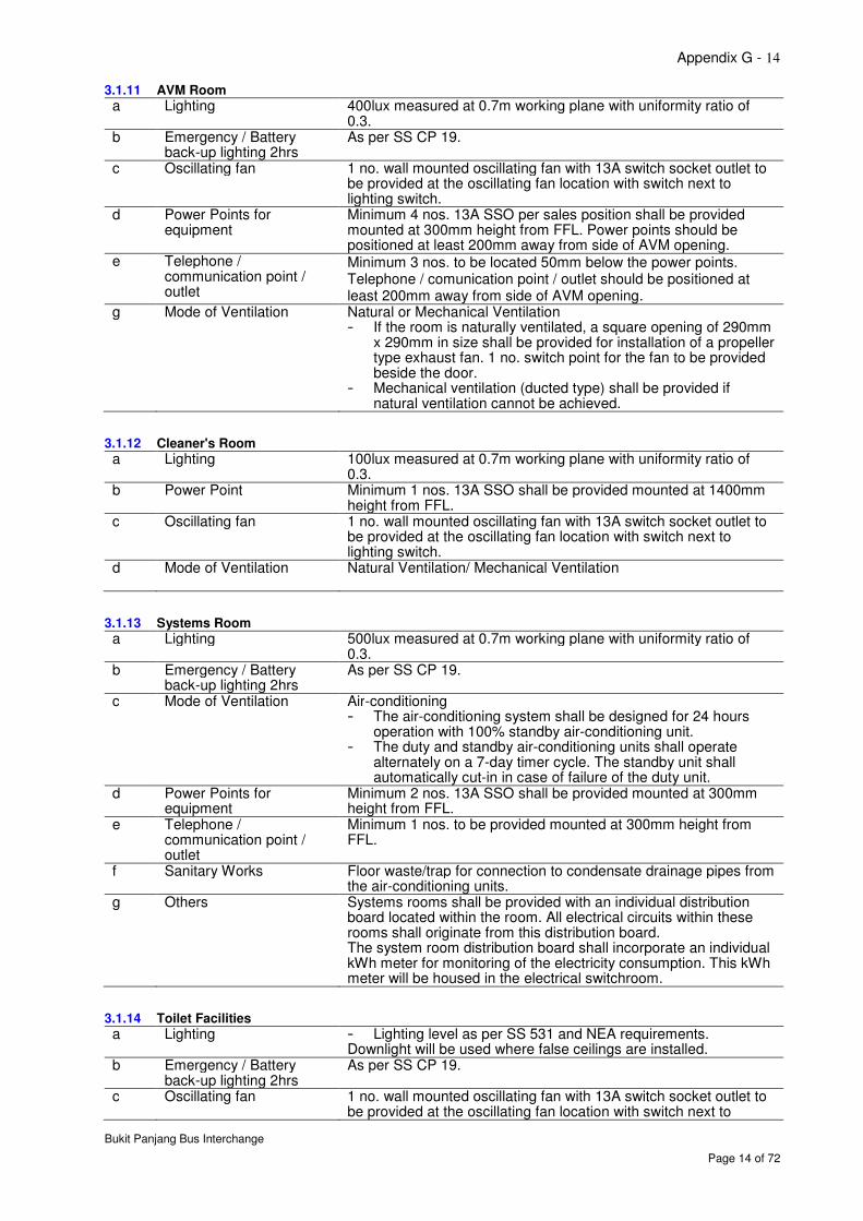
3.1.11 AVM Room
a Lighting 400lux measured at 0.7m working plane with uniformity ratio of 0.3.
b Emergency / Battery back-up lighting 2hrs
As per SS CP 19.
c Oscillating fan
1 no. wall mounted oscillating fan with 13A switch socket outlet to be provided at the oscillating fan location with switch next to lighting switch.
d Power Points for equipment
Minimum 4 nos. 13A SSO per sales position shall be provided mounted at 300mm height from FFL. Power points should be positioned at least 200mm away from side of AVM opening.
e Telephone / communication point / outlet
Minimum 3 nos. to be located 50mm below the power points. Telephone / comunication point / outlet should be positioned at least 200mm away from side of AVM opening.
g Mode of Ventilation
Natural or Mechanical Ventilation - If the room is naturally ventilated, a square opening of 290mm
x 290mm in size shall be provided for installation of a propeller type exhaust fan. 1 no. switch point for the fan to be provided beside the door.
- Mechanical ventilation (ducted type) shall be provided if natural ventilation cannot be achieved.
3.1.12 Cleaner's Room
a Lighting 100lux measured at 0.7m working plane with uniformity ratio of 0.3.
b Power Point Minimum 1 nos. 13A SSO shall be provided mounted at 1400mm height from FFL.
c Oscillating fan
1 no. wall mounted oscillating fan with 13A switch socket outlet to be provided at the oscillating fan location with switch next to lighting switch.
d Mode of Ventilation
Natural Ventilation/ Mechanical Ventilation
3.1.13 Systems Room
a Lighting 500lux measured at 0.7m working plane with uniformity ratio of 0.3.
b Emergency / Battery back-up lighting 2hrs
As per SS CP 19.
c Mode of Ventilation
Air-conditioning - The air-conditioning system shall be designed for 24 hours
operation with 100% standby air-conditioning unit. - The duty and standby air-conditioning units shall operate
alternately on a 7-day timer cycle. The standby unit shall automatically cut-in in case of failure of the duty unit.
d Power Points for equipment
Minimum 2 nos. 13A SSO shall be provided mounted at 300mm height from FFL.
e Telephone / communication point / outlet
Minimum 1 nos. to be provided mounted at 300mm height from FFL.
f Sanitary Works Floor waste/trap for connection to condensate drainage pipes from the air-conditioning units.
g Others
Systems rooms shall be provided with an individual distribution board located within the room. All electrical circuits within these rooms shall originate from this distribution board. The system room distribution board shall incorporate an individual kWh meter for monitoring of the electricity consumption. This kWh meter will be housed in the electrical switchroom.
3.1.14 Toilet Facilities
a Lighting - Lighting level as per SS 531 and NEA requirements. Downlight will be used where false ceilings are installed.
b Emergency / Battery back-up lighting 2hrs
As per SS CP 19.
c Oscillating fan
1 no. wall mounted oscillating fan with 13A switch socket outlet to be provided at the oscillating fan location with switch next to
Appendix G - 15
Bukit Panjang Bus Interchange
Page 15 of 72
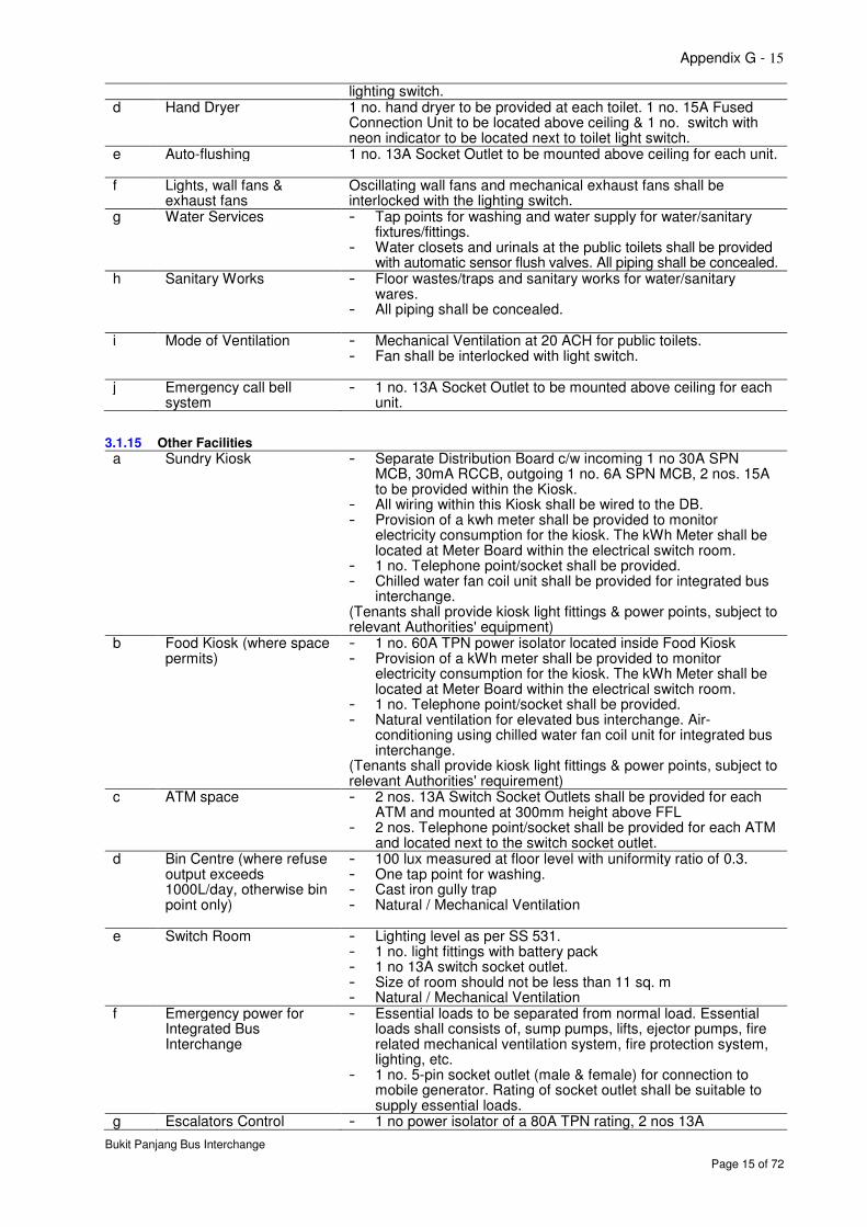
lighting switch. d Hand Dryer
1 no. hand dryer to be provided at each toilet. 1 no. 15A Fused Connection Unit to be located above ceiling & 1 no. switch with neon indicator to be located next to toilet light switch.
e Auto-flushing
1 no. 13A Socket Outlet to be mounted above ceiling for each unit.
f Lights, wall fans & exhaust fans
Oscillating wall fans and mechanical exhaust fans shall be interlocked with the lighting switch.
g Water Services - Tap points for washing and water supply for water/sanitary fixtures/fittings.
- Water closets and urinals at the public toilets shall be provided with automatic sensor flush valves. All piping shall be concealed.
h Sanitary Works - Floor wastes/traps and sanitary works for water/sanitary wares.
- All piping shall be concealed.
i Mode of Ventilation - Mechanical Ventilation at 20 ACH for public toilets. - Fan shall be interlocked with light switch.
j Emergency call bell system
- 1 no. 13A Socket Outlet to be mounted above ceiling for each unit.
3.1.15 Other Facilities
a Sundry Kiosk
- Separate Distribution Board c/w incoming 1 no 30A SPN MCB, 30mA RCCB, outgoing 1 no. 6A SPN MCB, 2 nos. 15A to be provided within the Kiosk.
- All wiring within this Kiosk shall be wired to the DB. - Provision of a kwh meter shall be provided to monitor
electricity consumption for the kiosk. The kWh Meter shall be located at Meter Board within the electrical switch room.
- 1 no. Telephone point/socket shall be provided. - Chilled water fan coil unit shall be provided for integrated bus
interchange. (Tenants shall provide kiosk light fittings & power points, subject to relevant Authorities' equipment)
b Food Kiosk (where space permits)
- 1 no. 60A TPN power isolator located inside Food Kiosk - Provision of a kWh meter shall be provided to monitor
electricity consumption for the kiosk. The kWh Meter shall be located at Meter Board within the electrical switch room.
- 1 no. Telephone point/socket shall be provided. - Natural ventilation for elevated bus interchange. Air-
conditioning using chilled water fan coil unit for integrated bus interchange.
(Tenants shall provide kiosk light fittings & power points, subject to relevant Authorities' requirement)
c ATM space - 2 nos. 13A Switch Socket Outlets shall be provided for each ATM and mounted at 300mm height above FFL
- 2 nos. Telephone point/socket shall be provided for each ATM and located next to the switch socket outlet.
d Bin Centre (where refuse output exceeds 1000L/day, otherwise bin point only)
- 100 lux measured at floor level with uniformity ratio of 0.3. - One tap point for washing. - Cast iron gully trap - Natural / Mechanical Ventilation
e Switch Room - Lighting level as per SS 531. - 1 no. light fittings with battery pack - 1 no 13A switch socket outlet. - Size of room should not be less than 11 sq. m - Natural / Mechanical Ventilation
f Emergency power for Integrated Bus Interchange
- Essential loads to be separated from normal load. Essential loads shall consists of, sump pumps, lifts, ejector pumps, fire related mechanical ventilation system, fire protection system, lighting, etc.
- 1 no. 5-pin socket outlet (male & female) for connection to mobile generator. Rating of socket outlet shall be suitable to supply essential loads.
g Escalators Control - 1 no power isolator of a 80A TPN rating, 2 nos 13A
Appendix G - 16
Bukit Panjang Bus Interchange
Page 16 of 72
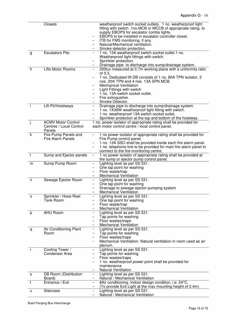
Closets
weatherproof switch socket outlets. 1 no. weatherproof light fitting with switch .1no.MCB or MCCB of appropriate rating. to supply EBOPS for escalator combs lights.
- EBOPS to be installed in escalator controller closet. - ITB for FMS monitoring, if any. - Natural/Mechanical ventilation. - Smoke detector protection.
g Escalators Pits - 1 no. 13A weatherproof switch socket outlet.1 no. Weatherproof light fittings with switch.
- Sprinkler protection. - Drainage pipe to discharge into sump/drainage system.
h Lifts Motor Rooms - 200lux measured at 0.7m working plane with a uniformity ratio of 0.3.
- 1 no. Dedicated lift DB consists of 1 no. 80A TPN isolator, 2 nos. 20A TPN and 4 nos. 13A SPN MCB.
- Mechanical Ventilation - Light Fittings with switch - 1 no. 13A switch socket outlet. - Fire extinguisher. - Smoke Detector.
i Lift Pit/Hoistways - Drainage pipe to discharge into sump/drainage system. - 1 no. 1X36W weatherproof light fitting with switch. - 1 no. weatherproof 13A switch socket outlet. - Sprinkler protection at the top and bottom of the hoistway.
j ACMV Motor Control Centres / Local Control Panels
1 no. power isolator of appropriate rating shall be provided for each motor control centre / local control panel.
k Fire Pump Panels and Fire Alarm Panels
- 1 no power isolator of appropriate rating shall be provided for Fire Pump control panel.
- 1 no. 13A SSO shall be provided inside each fire alarm panel. - 1 no. telephone line to be provided for main fire alarm panel to
connect to the fire-monitoring centre. l Sump and Ejector panels - 1 no power isolator of appropriate rating shall be provided at
the sump or ejector pump control panel. m Sump Pump Room - Lighting level as per SS 531.
- One tap point for washing - Floor waste/trap - Mechanical Ventilation
n Sewage Ejector Room - Lighting level as per SS 531. - One tap point for washing - Drainage to sewage ejector pumping system - Mechanical Ventilation
o Sprinkler / Hose Reel Tank Room
- Lighting level as per SS 531. - One tap point for washing - Floor waste/trap - Mechanical Ventilation
p AHU Room - Lighting level as per SS 531. - Tap points for washing - Floor wastes/traps - Mechanical Ventilation
q Air Conditioning Plant Room
- Lighting level as per SS 531. - Tap points for washing - Floor wastes/traps - Mechanical Ventilation. Natural ventilation in room used as air
plenum. r Cooling Tower /
Condenser Area - Lighting level as per SS 531. - Tap points for washing - Floor wastes/traps - 1 no. weatherproof power point shall be provided for
maintenance - Natural Ventilation
s DB Room (Distribution Board)
- Lighting level as per SS 531. - Natural / Mechanical Ventilation
t Entrance / Exit - #Air conditioning. Indoor design condition, i.e. 24°C. - (To provide Exit Light at the max mounting height of 2.4m)
u Staircase - Lighting level as per SS 531. - Natural / Mechanical Ventilation
Appendix G - 17
Bukit Panjang Bus Interchange
Page 17 of 72
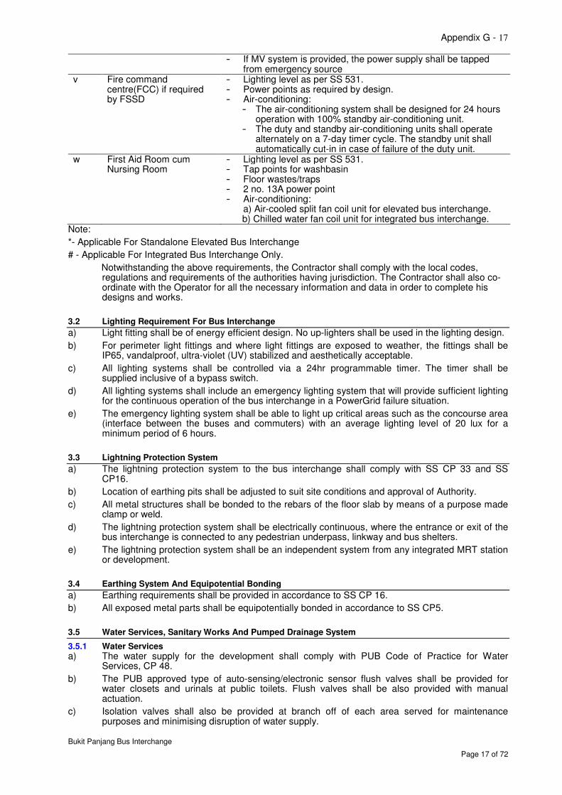
- If MV system is provided, the power supply shall be tapped from emergency source
v Fire command centre(FCC) if required by FSSD
- Lighting level as per SS 531. - Power points as required by design. - Air-conditioning:
- The air-conditioning system shall be designed for 24 hours operation with 100% standby air-conditioning unit.
- The duty and standby air-conditioning units shall operate alternately on a 7-day timer cycle. The standby unit shall automatically cut-in in case of failure of the duty unit.
w First Aid Room cum Nursing Room
- Lighting level as per SS 531. - Tap points for washbasin - Floor wastes/traps - 2 no. 13A power point - Air-conditioning:
a) Air-cooled split fan coil unit for elevated bus interchange. b) Chilled water fan coil unit for integrated bus interchange.
Note:
*- Applicable For Standalone Elevated Bus Interchange
# - Applicable For Integrated Bus Interchange Only.
Notwithstanding the above requirements, the Contractor shall comply with the local codes, regulations and requirements of the authorities having jurisdiction. The Contractor shall also co-ordinate with the Operator for all the necessary information and data in order to complete his designs and works.
3.2 Lighting Requirement For Bus Interchange
a) Light fitting shall be of energy efficient design. No up-lighters shall be used in the lighting design.
b) For perimeter light fittings and where light fittings are exposed to weather, the fittings shall be IP65, vandalproof, ultra-violet (UV) stabilized and aesthetically acceptable.
c) All lighting systems shall be controlled via a 24hr programmable timer. The timer shall be supplied inclusive of a bypass switch.
d) All lighting systems shall include an emergency lighting system that will provide sufficient lighting for the continuous operation of the bus interchange in a PowerGrid failure situation.
e) The emergency lighting system shall be able to light up critical areas such as the concourse area (interface between the buses and commuters) with an average lighting level of 20 lux for a minimum period of 6 hours.
3.3 Lightning Protection System
a) The lightning protection system to the bus interchange shall comply with SS CP 33 and SS CP16.
b) Location of earthing pits shall be adjusted to suit site conditions and approval of Authority.
c) All metal structures shall be bonded to the rebars of the floor slab by means of a purpose made clamp or weld.
d) The lightning protection system shall be electrically continuous, where the entrance or exit of the bus interchange is connected to any pedestrian underpass, linkway and bus shelters.
e) The lightning protection system shall be an independent system from any integrated MRT station or development.
3.4 Earthing System And Equipotential Bonding
a) Earthing requirements shall be provided in accordance to SS CP 16.
b) All exposed metal parts shall be equipotentially bonded in accordance to SS CP5.
3.5 Water Services, Sanitary Works And Pumped Drainage System
3.5.1 Water Services a) The water supply for the development shall comply with PUB Code of Practice for Water
Services, CP 48.
b) The PUB approved type of auto-sensing/electronic sensor flush valves shall be provided for water closets and urinals at public toilets. Flush valves shall be also provided with manual actuation.
c) Isolation valves shall also be provided at branch off of each area served for maintenance purposes and minimising disruption of water supply.
Appendix G - 18
Bukit Panjang Bus Interchange
Page 18 of 72
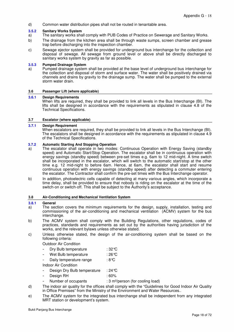
d) Common water distribution pipes shall not be routed in tenantable area.
3.5.2 Sanitary Works System a) The sanitary works shall comply with PUB Codes of Practice on Sewerage and Sanitary Works.
b) The drainage from the kitchen area shall be through waste sumps, screen chamber and grease trap before discharging into the inspection chamber.
c) Sewage ejector system shall be provided for underground bus interchange for the collection and disposal of sewage. All sewage from ground level or above shall be directly discharged to sanitary works system by gravity as far as possible.
3.5.3 Pumped Drainage System a) Pumped drainage system shall be provided at the base level of underground bus interchange for
the collection and disposal of storm and surface water. The water shall be positively drained via channels and drains by gravity to the drainage sump. The water shall be pumped to the external storm water drain.
3.6 Passenger Lift (where applicable)
3.6.1 Design Requirements When lifts are required, they shall be provided to link all levels in the Bus Interchange (BI). The lifts shall be designed in accordance with the requirements as stipulated in clause 4.8 of the Technical Specifications.
3.7 Escalator (where applicable)
3.7.1 Design Requirement When escalators are required, they shall be provided to link all levels in the Bus Interchange (BI). The escalators shall be designed in accordance with the requirements as stipulated in clause 4.9 of the Technical Specifications.
3.7.2 Automatic Starting And Stopping Operation a) The escalator shall operate in two modes: Continuous Operation with Energy Saving (standby
speed) and Automatic Start/Stop Operation. The escalator shall be in continuous operation with energy savings (standby speed) between pre-set times e.g. 6am to 12 mid-night. A time switch shall be incorporated in the escalator, which will switch to the automatic start/stop at the other time e.g. 12 mid-night to before 6am. Hence, at 6am, the escalator shall start and resume continuous operation with energy savings (standby speed) after detecting a commuter entering the escalator. The Contractor shall confirm the pre-set times with the Bus Interchange operator.
b) In addition, photoelectric cells capable of detecting at many various angles, which incorporate a time delay, shall be provided to ensure that nobody is riding on the escalator at the time of the switch-on or switch-off. This shall be subject to the Authority’s acceptance.
3.8 Air-Conditioning and Mechanical Ventilation System
3.8.1 General a) The section covers the minimum requirements for the design, supply, installation, testing and
commissioning of the air-conditioning and mechanical ventilation (ACMV) system for the bus interchange.
b) The ACMV system shall comply with the Building Regulations, other regulations, codes of practices, standards and requirements as set out by the authorities having jurisdiction of the works, and the relevant bylaws unless otherwise stated.
c) Unless otherwise stated, the design of the air-conditioning system shall be based on the following criteria:
Outdoor Air Condition
- Dry Bulb temperature : 32°C
- Wet Bulb temperature : 26°C
- Daily temperature range : 8°C
Indoor Air Condition
- Design Dry Bulb temperature : 24°C
- Design RH : 60%
- Number of occupants : 3 m²/person (for cooling load)
d) The indoor air quality for the offices shall comply with the “Guidelines for Good Indoor Air Quality in Office Premises” from the Ministry of the Environment and Water Resources..
e) The ACMV system for the integrated bus interchange shall be independent from any integrated MRT station or development’s system.
Appendix G - 19
Bukit Panjang Bus Interchange
Page 19 of 72
f) Air-conditioning for the concourse area shall be provided by means of a central air-conditioning system with conditioned air supplied to the air-conditioned spaces by means of floor-mounted air handling units (AHUs) or packaged units housed in the AHU rooms for ease of access for maintenance.
g) All ACMV equipment shall be provided with programmable 24 hours /7 days timer.
h) Vibration isolators shall be provided for the equipment and services in accordance with the manufacturers’ recommendations.
i) Pre-filters shall be provided for all fresh air intakes of the air-conditioning system.
j) The ACMV equipment, materials, installation, testing and commissioning shall also comply with National Productive and Quality Specifications (NPQS), Mechanical Specifications issued by the Building Control Authority unless otherwise stated.
k) Air-curtains shall be provided at the doors of the concourse areas to minimise air exchange between the air-conditioned and non-air-conditioned spaces.
l) All condensate drainpipes for the air-conditioning units(s) shall be concealed and connected to the nearest floor trap.
m) Where air-cooled split units are provided, weatherproof isolators of appropriate ratings shall be provided at each condenser unit location.
n) Unless specified otherwise, the ACMV system shall have sufficient redundancy such that in the event of failure of any of the equipment or component, not more than half of the cooling or ventilation requirements of the area served shall be affected.
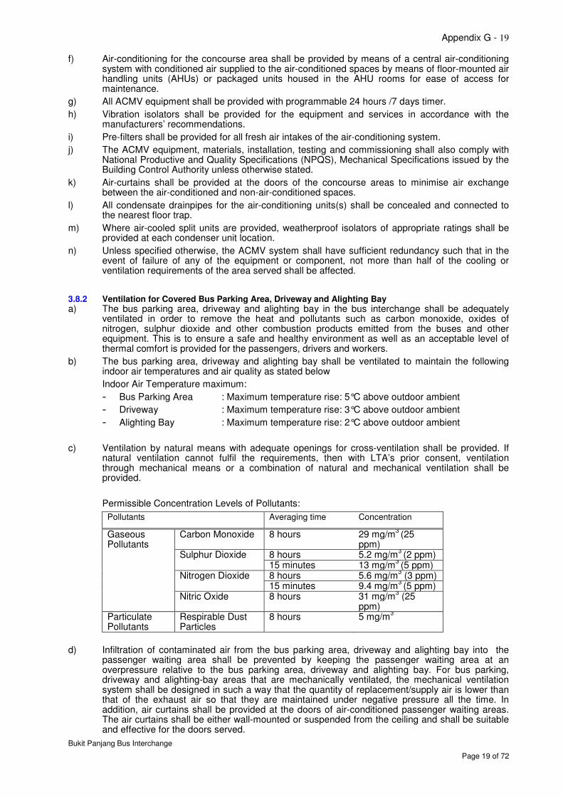
3.8.2 Ventilation for Covered Bus Parking Area, Driveway and Alighting Bay a) The bus parking area, driveway and alighting bay in the bus interchange shall be adequately
ventilated in order to remove the heat and pollutants such as carbon monoxide, oxides of nitrogen, sulphur dioxide and other combustion products emitted from the buses and other equipment. This is to ensure a safe and healthy environment as well as an acceptable level of thermal comfort is provided for the passengers, drivers and workers.
b) The bus parking area, driveway and alighting bay shall be ventilated to maintain the following indoor air temperatures and air quality as stated below
Indoor Air Temperature maximum:
- Bus Parking Area : Maximum temperature rise: 5°C above outdoor ambient
- Driveway : Maximum temperature rise: 3°C above outdoor ambient
- Alighting Bay : Maximum temperature rise: 2°C above outdoor ambient
c) Ventilation by natural means with adequate openings for cross-ventilation shall be provided. If natural ventilation cannot fulfil the requirements, then with LTA’s prior consent, ventilation through mechanical means or a combination of natural and mechanical ventilation shall be provided.
Permissible Concentration Levels of Pollutants:
Pollutants Averaging time Concentration
Gaseous Pollutants
Carbon Monoxide 8 hours 29 mg/m3 (25
ppm) Sulphur Dioxide 8 hours 5.2 mg/m
3 (2 ppm)
15 minutes 13 mg/m3 (5 ppm)
Nitrogen Dioxide 8 hours 5.6 mg/m3 (3 ppm)
15 minutes 9.4 mg/m3 (5 ppm)
Nitric Oxide 8 hours 31 mg/m3 (25
ppm) Particulate Pollutants
Respirable Dust Particles
8 hours 5 mg/m3
d) Infiltration of contaminated air from the bus parking area, driveway and alighting bay into the passenger waiting area shall be prevented by keeping the passenger waiting area at an overpressure relative to the bus parking area, driveway and alighting bay. For bus parking, driveway and alighting-bay areas that are mechanically ventilated, the mechanical ventilation system shall be designed in such a way that the quantity of replacement/supply air is lower than that of the exhaust air so that they are maintained under negative pressure all the time. In addition, air curtains shall be provided at the doors of air-conditioned passenger waiting areas. The air curtains shall be either wall-mounted or suspended from the ceiling and shall be suitable and effective for the doors served.
Appendix G - 20
Bukit Panjang Bus Interchange
Page 20 of 72
e) Fire and smoke in the bus parking area, driveway and alighting berth shall not spread into the passenger waiting area and adjacent development.
f) The ventilation system design shall take into consideration the expected peak number of buses operating in the bus interchange.
g) The areas served by mechanical ventilation shall incorporate a supply part and an exhaust part with minimum ventilation rate to meet the requirements specified above.
h) Supply outlets shall be located and evenly distributed at areas where passengers are likely to access and transit e.g. alighting bay, to maintain a lower temperature at these areas relative to other areas e.g. bus parking areas and driveway. The supply air shall be drawn directly from the external and its intake shall not be less than 5m from any exhaust discharge openings.
i) Exhaust outlets shall be located at areas where heat and exhaust from buses are expected so that the heat and emission are removed as close to the source as possible. At least 50% of the exhaust air shall be extracted at low level not exceeding 650mm above the finished floor level, as measured from the top of the grille to the finished floor level. Exhaust outlets shall also be located close to the ceiling soffit to minimise the accumulation of heat and pollutants at the ceiling space.
j) The discharge points of the exhaust ventilation system shall be arranged to discharge directly to the external. They shall not be less than 5m away from any air circulating and ventilating inlets, openable windows and occupied areas, pedestrian thoroughfares, trafficable areas, areas of public access and exhaust discharges from kitchens. They shall also not face or discharge in the direction of any adjacent residential building.
k) When locating the discharge points, the influence of adjacent buildings and prevailing wind direction and the wind distribution over these buildings shall be taken into account. It shall be located away from the downwind of air intakes of the building.
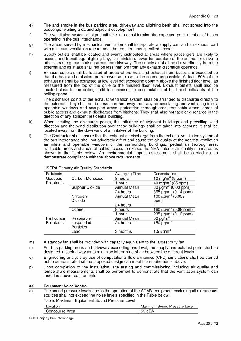
l) The Contractor shall ensure that the exhaust air discharge from the exhaust ventilation system of the bus interchange shall not adversely affect and cause the air quality at the nearest ventilation air inlets and openable windows of the surrounding buildings,, pedestrian thoroughfares, trafficable areas and areas of public access to exceed the NEA outdoor air quality standards as shown in the Table below. An environmental impact assessment shall be carried out to demonstrate compliance with the above requirements.
USEPA Primary Air Quality Standards
Pollutants Averaging Time Concentration
Gaseous Pollutants
Carbon Monoxide 8 hours 10 mg/m3 (9 ppm)
1 hour 40 mg/m3 (35 ppm)
Sulphur Dioxide Annual Mean 80 µg/m3 (0.03 ppm)
24 hours 365 µg/m3 (0.14 ppm)
Nitrogen Dioxide
Annual Mean 100 µg/m3 (0.053
ppm) 24 hours -
Ozone 8 hours 160 µg/m3 (0.08 ppm)
1 hour 235 µg/m3 (0.12 ppm)
Particulate Pollutants
Respirable suspended Particles
Annual Mean 50 µg/m3
24 hours 150 µg/m3
Lead 3 months 1.5 µg/m3
m) A standby fan shall be provided with capacity equivalent to the largest duty fan.
n) For bus parking areas and driveway exceeding one level, the supply and exhaust parts shall be designed in such a way as to minimise intermixing of air between the different levels.
o) Engineering analysis by use of computational fluid dynamics (CFD) simulations shall be carried out to demonstrate that the proposed design can meet the requirements above.
p) Upon completion of the installation, site testing and commissioning including air quality and temperature measurements shall be performed to demonstrate that the ventilation system can meet the above requirements.
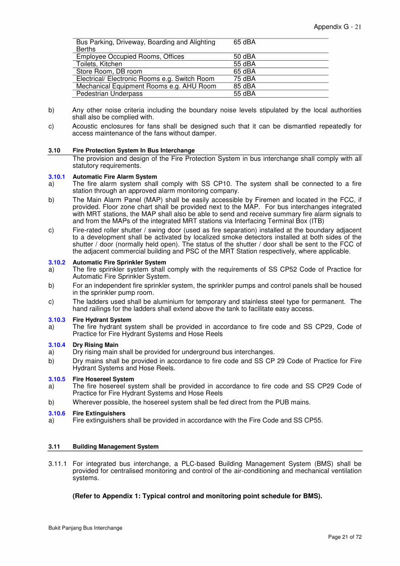
3.9 Equipment Noise Control
a) The sound pressure levels due to the operation of the ACMV equipment excluding all extraneous sources shall not exceed the noise levels specified in the Table below.
Table: Maximum Equipment Sound Pressure Level
Location Maximum Sound Pressure Level
Concourse Area 55 dBA
Appendix G - 21
Bukit Panjang Bus Interchange
Page 21 of 72
Bus Parking, Driveway, Boarding and Alighting Berths
65 dBA
Employee Occupied Rooms, Offices 50 dBA Toilets, Kitchen 55 dBA Store Room, DB room 65 dBA Electrical/ Electronic Rooms e.g. Switch Room 75 dBA Mechanical Equipment Rooms e.g. AHU Room 85 dBA Pedestrian Underpass 55 dBA
b) Any other noise criteria including the boundary noise levels stipulated by the local authorities shall also be complied with.
c) Acoustic enclosures for fans shall be designed such that it can be dismantled repeatedly for access maintenance of the fans without damper.
3.10 Fire Protection System In Bus Interchange
The provision and design of the Fire Protection System in bus interchange shall comply with all statutory requirements.
3.10.1 Automatic Fire Alarm System a) The fire alarm system shall comply with SS CP10. The system shall be connected to a fire
station through an approved alarm monitoring company.
b) The Main Alarm Panel (MAP) shall be easily accessible by Firemen and located in the FCC, if provided. Floor zone chart shall be provided next to the MAP. For bus interchanges integrated with MRT stations, the MAP shall also be able to send and receive summary fire alarm signals to and from the MAPs of the integrated MRT stations via Interfacing Terminal Box (ITB)
c) Fire-rated roller shutter / swing door (used as fire separation) installed at the boundary adjacent to a development shall be activated by localized smoke detectors installed at both sides of the shutter / door (normally held open). The status of the shutter / door shall be sent to the FCC of the adjacent commercial building and PSC of the MRT Station respectively, where applicable.
3.10.2 Automatic Fire Sprinkler System a) The fire sprinkler system shall comply with the requirements of SS CP52 Code of Practice for
Automatic Fire Sprinkler System.
b) For an independent fire sprinkler system, the sprinkler pumps and control panels shall be housed in the sprinkler pump room.
c) The ladders used shall be aluminium for temporary and stainless steel type for permanent. The hand railings for the ladders shall extend above the tank to facilitate easy access.
3.10.3 Fire Hydrant System a) The fire hydrant system shall be provided in accordance to fire code and SS CP29, Code of
Practice for Fire Hydrant Systems and Hose Reels
3.10.4 Dry Rising Main a) Dry rising main shall be provided for underground bus interchanges.
b) Dry mains shall be provided in accordance to fire code and SS CP 29 Code of Practice for Fire Hydrant Systems and Hose Reels.
3.10.5 Fire Hosereel System a) The fire hosereel system shall be provided in accordance to fire code and SS CP29 Code of
Practice for Fire Hydrant Systems and Hose Reels
b) Wherever possible, the hosereel system shall be fed direct from the PUB mains.
3.10.6 Fire Extinguishers a) Fire extinguishers shall be provided in accordance with the Fire Code and SS CP55.
3.11 Building Management System
3.11.1 For integrated bus interchange, a PLC-based Building Management System (BMS) shall be provided for centralised monitoring and control of the air-conditioning and mechanical ventilation systems.
(Refer to Appendix 1: Typical control and monitoring point schedule for BMS).
Appendix G - 22
Bukit Panjang Bus Interchange
Page 22 of 72
4 TECHNICAL SPECIFICATIONS
4.1 Code And Regulation
In addition to local requirements, equipment and system design shall also comply with the following codes of practice and standards:
- British Standards (BS)
- International Electrotechnical Commission (IEC)
- International Standards Organization (ISO)
- ASHRAE – American Society of Heating, Refrigerating and Air-Conditioning Engineers
- Guidelines for Good Indoor Air Quality in Office Premises
- AMCA - Air Movement and Control Association (USA)
- ANSI - American National Standards Institute (USA)
- ARI - Air-conditioning & Refrigeration Institute
- ASTM - American Society of Testing and Materials
- HVCA - Heating and Ventilation Contractors Association (UK)
- SMACNA - Sheet Metal and Air-conditioning Contractors’ National Association Inc. (USA)
- UL - Underwriters Laboratory
4.2 LV Power Systems
4.2.1 LV Main Switchboard
4.2.1.1 Particular Requirements
a) The LV metal clad main switchboard shall be of Form 4, floor standing and type-tested assembly (TTA) as defined in IEC 60439-1: Part 1.
b) The main switchboards shall be vermin proof with ventilation louvers complete with insect netting at the back and sides of the switchboards and the finished assembly shall conform to IP 42 in accordance with IEC 60529. Anti-condensation heaters with indication lamps shall be provided in each compartment. The anti-condensation heating elements shall be suitable for connection to the main electricity supply (230V AC). The heater shall be thermostatically controlled and easily accessible for maintenance replacement.
c) Incoming circuit breakers shall be provided with the capability of being padlocked in the "OFF" position.
d) 20% spare panel space shall be provided for future expansion purposes. Busbars shall be extended as necessary and drilled for future connection of conductors.
e) As-built line diagram, control circuit and layout plan shall be inserted in a permanent pocket on the inner side of the panel door of each switchboard. All diagrams must be endorsed by LEW of the appropriate grade.
f) The Contractor shall provide the following in the LV Switchrooms
i. Rubber mats of at least 5mm thick and 600mm wide shall be provided for the entire length in front of all floor mounted switchboards.
ii. Statutory safety notices, regulations and instruction for resuscitation and treatment after electrical shock.
iii. Danger signs in 4 languages displayed on switchboards / control panels / doors for electrical rooms complying with the requirements of the Energy Market Authority.
iv. Suitable metal cabinet (A2 size) for writing purposes, installed next to the framed single-line drawing.
v. Key cabinets with sufficient capacity for the number of keys required for padlocking all circuit breakers and all the keys for control switches on the entire LV main switchboards.
vi. A4 size log-book for recording of all access to and activities in the LV Switchroom.
4.2.1.2 Busbars and Supports
a) Busbars shall be made of hard drawn, electro-tinned high conductivity, bare rectangular solid copper bars complying with BS EN 13601. Full size phase and neutral busbars shall be provided.
Appendix G - 23
Bukit Panjang Bus Interchange
Page 23 of 72
b) The busbar shall be colour code in compliance to latest CP5 for phase identification. Phase identification label shall totally wrap non-adhesive heat shrinkable type around the busbars.
c) The minimum busbar clearance between phases and between phases and earth shall be in conformance to BS 159.
d) Busbar shall be constructed in such manner so as to allow for future extension without dismantling and modifying of the busbars and busbar mounting. Busbar shall run throughout the entire length of the switchboard.
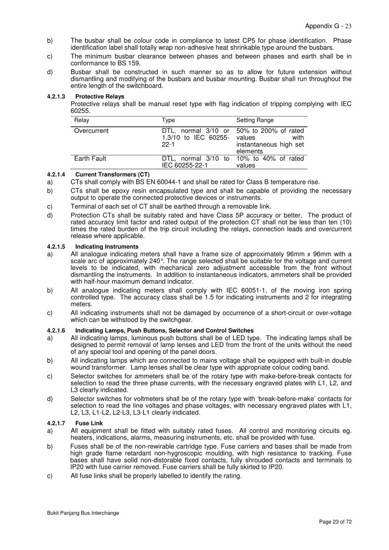
4.2.1.3 Protective Relays
Protective relays shall be manual reset type with flag indication of tripping complying with IEC 60255.
Relay Type Setting Range
Overcurrent DTL, normal 3/10 or 1.3/10 to IEC 60255-22-1
50% to 200% of rated values with instantaneous high set elements
Earth Fault DTL, normal 3/10 to IEC 60255-22-1
10% to 40% of rated values
4.2.1.4 Current Transformers (CT)
a) CTs shall comply with BS EN 60044-1 and shall be rated for Class B temperature rise.
b) CTs shall be epoxy resin encapsulated type and shall be capable of providing the necessary output to operate the connected protective devices or instruments.
c) Terminal of each set of CT shall be earthed through a removable link.
d) Protection CTs shall be suitably rated and have Class 5P accuracy or better. The product of rated accuracy limit factor and rated output of the protection CT shall not be less than ten (10) times the rated burden of the trip circuit including the relays, connection leads and overcurrent release where applicable.
4.2.1.5 Indicating Instruments
a) All analogue indicating meters shall have a frame size of approximately 96mm x 96mm with a scale arc of approximately 240°. The range selected shall be suitable for the voltage and current levels to be indicated, with mechanical zero adjustment accessible from the front without dismantling the instruments. In addition to instantaneous indicators, ammeters shall be provided with half-hour maximum demand indicator.
b) All analogue indicating meters shall comply with IEC 60051-1, of the moving iron spring controlled type. The accuracy class shall be 1.5 for indicating instruments and 2 for integrating meters.
c) All indicating instruments shall not be damaged by occurrence of a short-circuit or over-voltage which can be withstood by the switchgear.
4.2.1.6 Indicating Lamps, Push Buttons, Selector and Control Switches
a) All indicating lamps, luminous push buttons shall be of LED type. The indicating lamps shall be designed to permit removal of lamp lenses and LED from the front of the units without the need of any special tool and opening of the panel doors.
b) All indicating lamps which are connected to mains voltage shall be equipped with built-in double wound transformer. Lamp lenses shall be clear type with appropriate colour coding band.
c) Selector switches for ammeters shall be of the rotary type with make-before-break contacts for selection to read the three phase currents, with the necessary engraved plates with L1, L2, and L3 clearly indicated.
d) Selector switches for voltmeters shall be of the rotary type with ‘break-before-make’ contacts for selection to read the line voltages and phase voltages, with necessary engraved plates with L1, L2, L3, L1-L2, L2-L3, L3-L1 clearly indicated.
4.2.1.7 Fuse Link
a) All equipment shall be fitted with suitably rated fuses. All control and monitoring circuits eg. heaters, indications, alarms, measuring instruments, etc. shall be provided with fuse.
b) Fuses shall be of the non-rewirable cartridge type. Fuse carriers and bases shall be made from high grade flame retardant non-hygroscopic moulding, with high resistance to tracking. Fuse bases shall have solid non-distorable fixed contacts, fully shrouded contacts and terminals to IP20 with fuse carrier removed. Fuse carriers shall be fully skirted to IP20.
c) All fuse links shall be properly labelled to identify the rating.
Appendix G - 24
Bukit Panjang Bus Interchange
Page 24 of 72
4.2.1.8 Panel Heaters
a) Each section of the MSB shall be fitted with a panel heater operated on main supply and rated at not less than 60W per 1.5cu.m volume. The heaters shall be shrouded and mounted at the bottom of the switchboard.
b) The heaters shall be individually fused and fitted with rotary ON/OFF selector switch, thermostatic controls and a lamp to indicate the energisation of the heaters at the front.
4.2.1.9 Earthing
a) A tinned copper earth bar complying with SS CP 5 shall be provided along the whole length of the switchboard.
4.2.1.10 Labelling
a) All labels shall be manufactured from laminated traffolyte or similar plastic materials, engraved and fixed by stainless steel screws.
4.2.1.11 Internal and Control Wiring
a) All internal and control wiring shall be 600V/1000V grade PVC insulated Copper cable to IEC 60228 Class 2.
b) All internal and control wiring shall be 600V/1000V grade PVC insulated copper cable to IEC 60228 Class 2.
c) Each wire shall be fitted at both ends with a white ferrule and black engraved inscription to correspond with the connection diagram.
4.2.2 LV Distribution Board (DB)
4.2.2.1 General
a) DBs shall be of metal enclosed, factory built type corresponding IEC-Recommendations No. 60439, 60144 and 60157.
b) Each DB is to be labelled properly with reverse engraved name plate secured by stainless steel screws. The details of the labels are to be approved by the Authority before fabrication.
4.2.2.2 Panel Construction
a) The DB enclosure (panels/doors) shall be made of electro-galvanised steel sheets (minimum thickness 2 mm) and finished with epoxy powder coating (minimum 60 micron) colour to the acceptance.
b) The enclosure shall be completed with hinged doors and to be provided with standardised key lock and 3 sets of key.
c) The distribution board shall be composed from standardised items, enabling easy exchange or replacement of faulty equipment.
d) The distribution board shall be supplied to minimum IP 44. In areas where the distribution board is exposed to weather, the distribution board shall be to a minimum IP 54. Proper four language warning signs indicating danger and voltage level shall be provided.
e) Each distribution board shall be supplied complete with top/bottom removable metal plates for cable entry and exit.
f) Unless otherwise approved, access to the boards shall be from the front, the doors shall be furnished with lift off hinges to permit an opening enabling an unrestricted access to the board interior. All doors and covers shall be fitted with moulded gaskets of non-ageing material.
g) The board interior apparatus shall be fixed mounted on back plates of reinforced steel for rigid support and covered with a transparent front panel making the access to the live parts impossible. The circuit breakers shall be mounted such that the above-mentioned front panel need not be removed in order to operate any breakers. The meters and indication lights shall be installed in the door openings and be visible without opening the door.
h) The distribution boards shall be provided with tinned copper conductor busbars rated for the appropriate continuous current and short circuit current.
i) Each distribution board shall also be furnished with neutral and earthing busbars having the same rating as the phase buses.
j) Each distribution board shall be fitted with a multi-terminal earth bar with one terminal for each outgoing circuit. Connection to this earth bar shall be direct without dependence on exposed conductive parts of the enclosure and shall reflect the circuits served, i.e. Circuit no. 1 in terminal no. 1 etc.
k) Each distribution board shall be fitted with a multi-terminal neutral bar with one terminal for each outgoing circuit. Connection to this neutral bar shall be direct without dependence on exposed conductive parts of the enclosure and shall reflect the circuits served, i.e. Circuit no. 1 in terminal no. 1 etc.
Appendix G - 25
Bukit Panjang Bus Interchange
Page 25 of 72
l) Each distribution board shall be fitted with an earth stud located in an accessible position on the inside of the board. All metal parts of the board except current carrying parts shall be bonded together electrically and to the earth bar.
m) The construction of the distribution boards shall be such that no cable is subjected to bend of internal radius less than four times the overall diameter of the cable.
n) As-built line diagram, control circuit and layout plan shall be inserted in a permanent pocket on the inner side of the panel door of each distribution board. All diagrams must be endorsed by LEW of the appropriate grade.
4.2.3 Overground (OG) Box a) The OG box shall be outdoor type. All components of the OG box shall be accommodated in a
weatherproof housing complying to IP 54 and of robust construction.
b) The housing shall be 3mm thick aluminium, electrotatically coated with pure polyester powder of thickness between 80 micons and 100 microns. The OG box shall be spray with 1 coat of primer and 2 finishing coats of paint.
c) Adequate ventilation shall be provided to permit natural circulation of air. The ventilation apertures shall be suitably screened to prevent the entry of vermin and other foreign bodies.
d) The OG box shall be provided with a root of ample strength and suitable for mounting on a concrete/brick footing. A concrete plinth of minimum height of 300mm shall be provided for mounting of the OG box.
e) Hinged door complete with standardised lockset shall be provided at the front of the OG box. The door locks and keys for all the distribution boxes shall be similar and interchangeable. 3 sets of keys shall be provided for each OG box.
f) Surge Protection Devices (SPD) shall be of Type 2, DIN-rail type with standard 8/20 wave characteristics complying to IEC 61643-1.
g) SPD shall have minimum discharge ratings of 40kA and shall be provided by a dedicated miniature circuit breaker that has been tested to coordinate with the manufacturer's SPDs in accordance to IEC 60364.
h) SPD shall have the choice of a light indicator or mechanical indicator for end of life.
4.2.4 Switchgear, Apparatus And Internal Wiring
4.2.4.1 Moulded Case Circuit Breakers (MCCBs)
a) MCCBs shall comply with IEC 60947-2 : Part 2, short-circuit performance utilisation category B and shall have all mechanical and live metallic components completely enclosed within an all insulating moulded case.
b) MCCB shall have over-current tripping mechanism of the thermal magnetic, temperature compensated type to give time delay overload circuit protection and instantaneous short-circuit interruption. The operating characteristic shall be such that the time delay on overload tripping is inversely proportional to the overcurrent up to a threshold value of approximately seven times the rated current at 40°C.
c) MCCB shall be provided with a shunt trip. The shunt trip unit shall be controlled by an earth fault current sensing device and static electronic circuitry providing an adjustable earth leakage tripping range between 1 to 5A and an adjustable tripping time of 0 to 5 seconds. An indicating lamp with lamp test and reset buttons shall also be provided to indicate MCCB tripped status on earth fault.
4.2.4.2 Miniature Circuit Breakers
a) Miniature Circuit Breakers (MCBs) shall comply with IEC 60947-2. It shall be single-phase, air-break type equipped for manual control and with automatic overcurrent trip-free mechanism (bimetal device for overload-protection and electromagnetic device for short-circuit instantaneous tripping).
b) A minimum breaking capacity, corresponding to the busbar fault-level indicated on the drawings/or specification shall be guaranteed.
4.2.4.3 Residual Current Circuit Breaker
a) Residual Current Circuit Breaker (RCCBs) shall be of PSB approved type and manufactured to SS 97 or IEC 61008-1.
4.2.4.4 Programmable Timers
a) Timer input voltage shall be powered by AC 100- 240VAC (+10%/-15%, 50Hz)
b) The timer shall conform to:
- Noise Immunity. : IEC6100-4-4, 2 kV (power supply line).
- Ambient operating temperature : 0 to 55 oC
- Humidity: 10% - 100%
Appendix G - 26
Bukit Panjang Bus Interchange
Page 26 of 72
c) The Timer shall have the following programmable features:
- Programmable: With input and output conditions per line.
- Basic CPU Input/ Output : Min 3 inputs and 3 outputs
d) All outputs should have a relay switching capacity of 5A at 240VAC with independent common.
e) The Timer Central Processing Unit (CPU) shall be provided with built-in real-time clock and calendar functions. The real time clock should have an accuracy of +/- 6 mins max. per year. The data of real time clock, calendar, holding bits, holding timers and counter present value shall be held by a non-battery system for a minimum of 48 hours for prolonged power interruptions.
f) The Timer program and system setting data shall be stored in internal EEPROM to prevent loss of setting/program during power failure.
g) The Timer shall have the following features and functions:
- Front panel LCD display with backlight. Backlight can be automatically cut-off through adjustable settings to save the lifespan of backlight.
- Input filters settings to prevent noise-related malfunctions such as false triggering of inputs.
- Password protection function to prevent unauthorized modification of Timer programs and settings.
h) The Timer shall provide RS232C communication port or infrared port for downloading of program and setting.
i) The Timer shall support communications via RS232C to host devices such as computers and Personal Digital Assistant (PDA).
j) The Timer system shall be equipped with the Windows Based software programming tools and drivers for the set-up of communication between Timer and host devices.
k) The Timer shall be provided with application software tool running on Windows CE powered PDAs to allow setting of programs and the download/upload of the settings.
l) All Timer technical details and full communication protocols shall be provided.
m) The Timer shall have self-diagnostic functions and shall be displayed on the CPU LCD. All errors shall be communicated back to host via the RS232C communication port or infrared port.
n) Factory test certificates shall be submitted to the Authority for verification.
4.2.4.5 Contactors
a) Contactors shall comply with IEC 60947-4 and of suitable rating. They shall be provided with main contacts capable of at least 105 switching operations and at least two auxiliary contacts for remote control (230V, AC). Contactors for lighting control shall be of Utilisation Category AC1, Class 3.
4.2.4.6 Power Supply Company’s Meter board
a) Power Supply Company’s meter board shall be installed for each OG Box in accordance with the requirements of the “Handbook on application for electricity supply”. There shall be one-meter board for each OG Box as shown on the drawings.
b) All arrangement for installation of the Power Supply Company’s meter, application for supply turn-on including liaison, co-ordination and obtaining power supply company’s approval for all the meter boards shall be included as part of the work. All fees and charges incurred shall be deemed to be included in the tender offer.
4.2.4.7 Internal Wiring
a) All internal wiring in each item of equipment shall be installed in wiring channels or conduits as far as possible. Exposed wiring shall be kept to a minimum but where necessary the wires shall be formed into compact groups suitably bound together and properly supported. Non-metallic materials are preferable for the channels or conduits.
b) All conductors shall be terminated with suitable pressure type terminal lugs or proper sizes for terminal studs at the terminals blocks or shall be terminated in a manner compatible to the terminals of the instruments.
c) All conductors shall run continuously between terminal studs without splices or taps.
d) All conductors shall be labelled at each termination with wire number as designated on the circuit diagrams.
e) All internal wiring conductors shall be stranded copper wire, not less than 450/750 V class PVC insulation.
f) Conductor colour coding shall be as per the latest edition of SS CP 5.
4.2.5 LV Cables
4.2.5.1 PVC/PVC and PVC Cable
a) PVC/PVC cables & PVC cables shall be 600/1000 volt and 450/750 volt grade respectively consisting of high conductivity copper wire.
Appendix G - 27
Bukit Panjang Bus Interchange
Page 27 of 72
b) The cables shall be manufactured to SS 358-3 / BS 6004
4.2.5.2 PVC/SWA/PVC Cable
a) Cables of this type shall be 600/1000 V grade consisting of high conductivity copper wire, insulated and sheathed with polyvinyl chlorine. Cable of this type shall be manufactured to IEC 502.
b) PVC insulated cores shall be sheathed with PVC, which shall served as bedding for galvanised single steel wire armouring. The nominal diameter of the wire armour shall not be less than 1.6 mm. All armour cable shall be terminated using a proper gland.
4.2.5.3 Cable Installation
a) All cables shall be adequately protected against risk of mechanical damage to which they may be liable in normal conditions of service.
b) All cables shall be provided with identification labels at each end.
c) Cable joints and splices shall be prohibited.
d) Where cables pass through holes in metalwork, precautions shall be taken to prevent abrasion of the cables on any sharp edges.
e) Where appropriate, final connections to fixed equipment shall be by means of cables in flexible conduits.
4.2.6 Ancillary Equipment
4.2.6.1 Switches
a) Switches shall be of the quick make, slow break type with silent, totally enclosed switch action and solid silver alloy contacts. Switched socket outlets for indoor use shall be housed in suitable galvanised steel boxes to BS 4662 with conduit knockouts.
b) All switches associated with essential supplies shall be provided with red rocker switches.
4.2.6.2 Switch Socket Outlets
a) Switched socket outlets shall be single pole (13 Amp), 3 rectangular pin switch shuttered outlets, either surface or flush mounting according to location. All switched socket outlets shall be EMA approved type and tested by accredited testing body and each shall have a safety mark sticker.
b) Switches shall be of the quick make, slow break type with silent, totally enclosed switch action and solid silver alloy contacts. Switched socket outlets for indoor use shall be housed in suitable galvanised steel boxes to BS 4662 with conduit knockouts.
c) 15 ampere switched socket outlets shall be 3 pin round type to BS 546 shuttered, of a finish similar to 13 ampere switched socket outlets and mounted in flush steel conduit boxes.
d) Switched socket outlets in all mechanical plant rooms, electrical sub-stations and switch rooms shall be of the metal-clad type.
e) 15-ampere weatherproof socket outlets shall be of 3-pin type. Earth terminal shall be provided inside the socket outlet.
4.2.6.3 Isolators
a) Isolators shall be of either double pole or four poles with current ratings fit for the purpose and shall be enclosed, metal-clad with positive quick-make and quick-break action. Padlock facility shall be provided such that the isolator shall be locked in the position.
b) Isolators shall be capable of passing and also interrupting their full rated current safely and without damage. Ferrous materials shall be galvanised, switch handles shall be interlocked to prevent opening the over with the switch “ON”.
4.2.6.4 Fused Connection Unit
a) Fused connection unit shall be single pole (13 Amp), unswitched type, either with or without neon indicator and cable outlet. All fused connection unit shall be EMA approved type and tested by accredited testing body and each shall have a safety mark sticker.
b) Fused connection unit for indoor use shall be housed in suitable galvanised steel boxes to BS 4662 with conduit knockouts.
c) 15 ampere fused connection unit shall be of a finish similar to 13 ampere switched socket outlets and mounted in flush steel conduit boxes.
d) All fused connection unit in all mechanical plant rooms, electrical sub-stations and switch rooms shall be of the metal-clad type.
4.3 Lighting Fixtures And Installation
4.3.1 General a) All components within the luminaries shall preferably be from the same manufacturer to ensure
compatibility. All similar items of equipment shall be interchangeable.
Appendix G - 28
Bukit Panjang Bus Interchange
Page 28 of 72
b) Unless otherwise specified, all luminaries offered shall be as per manufacturer’s standard, except that all luminaries shall be modified, if not already catered for, to accept conduit termination, without affecting the quality of the product.
c) All fittings shall be corrected to a power factor of not less than 0.8 lagging individually.
d) All fittings shall be supplied complete with control gear, lamps etc.
4.3.2 Types of Lamps
4.3.2.1 Fluorescent Lamps
a) Fluorescent Tubes
- T5 fluorescent tubes shall be manufactured complying to BS EN 60081 with bi-pin lamp cap. High efficacy tubes (minimum 86 lumens per watt) with colour rendering index of 827 and colour temperature of 2700oK shall be used.
- The guaranteed minimum life expectancy of the lamp shall be 5,000 hours.
b) Fluorescent Lamps control gears
- Ballast for the fluorescent fittings shall be electronic ballast type.
i) The electronic ballast shall be designed to operate at 50Hz nominal frequency and at nominal voltages indicated on the label, 220-240V, 50-60Hz.
ii) The electronic ballast shall operate at frequency higher than 41kHz to avoid any interruption with other electrical component operating at a lower frequency.
iii) The electronic ballast shall comply to the following standard and requirements:
• Performance requirement : IEC 60929 & 60928
• Harmonics requirement : IEC 61000-3-2
• Radio frequency interference : CISPR 15, ad 7.1 / EN55015
• Immunity to interference : EN 61547 iv) The electronic ballast must have the CE, ENEC or EEI indication. v) The power factor should be greater than 0.97. vi) The design life of the electronic ballast shall be 50,000 hours at measuring point
temperature (Tc) of 70 Degree Celcius. vii) The failure rate of the ballast should be less than 0.2% per 1000 hours of operation.
- Starters shall be of self resettable electronic type complete with radio interference suppression capacitor.
- Power factor corrections capacitors shall comply with BS EN 61048, BS EN 61049 and fitted with quick connect terminals in lieu of leads. One capacitor in each fluorescent fitting to correct power factor to 0.85 lagging shall be provided.
4.3.2.2 High Pressure Discharge Lamp
a) High Pressure Sodium Vapour Lamp
- The high-pressure sodium vapour lamp shall be ellipsoidal in shape (except for SON/T which shall be tubular in shape) and shall be fitted with standard E40 nickel-plated cap (except for 70W SON which shall have a E27 cap) and suitable for use on 230V mains supply. The lamp shall have a minimum efficacy of 90 lm/watt. The colour temperature shall be 2100oK.
- The start-up time for the lamp to start from cold to reach its 80% of full light output shall be within 3 to 4 minutes. And the maximum restrike time of the lamp shall not exceed 1 minute.
- The guaranteed minimum life expectancy of the lamp shall be 10,000 hours.
b) High Pressure lamp control gears
- Lamp control gears (ballasts, igniters, capacitors) of the high-pressure lamp shall be designed to reliably start and operate the lamp in the ambient conditions and within the limit specified by the lamp manufacturer.
- Ballast shall be auto-regulator; precision wound type, with high power factor and shall have a guaranteed life of 10 years. The ballast shall be tropicalised and encapsulated in non-melt resin (155
oC) to ensure maximum protection from moisture and corrosion. The noise level
shall be less than 30dBA at a distance of 1 meter. All ballasts shall reliably operate the high-pressure lamps at mains voltage of 200V to 245V.
- Ballast temperature shall not exceed the maximum permissible operating temperature of the ballast insulating materials. Ballast with known cooler temperature will be preferred. Ballast offered shall be the low loss type.
- Power factor of the lamp circuit shall be maintained above 0.85 lagging. Power correcting capacitor shall comply with SS123 and BS EN 61048, BS EN 61049 and shall be metallised polypropylene type.
- Electronic igniters shall be totally enclosed type. It shall ensure quick start-up and quick restrike of the high-pressure lamp. The ignitron shall have the ability to sense a failed lamp
Appendix G - 29
Bukit Panjang Bus Interchange
Page 29 of 72
and switch off to avoid high voltage stress and high current on the ballast and avoid creating radio interference.
4.3.3 Types of Light Fixtures
4.3.3.1 Recessed Fittings
Recessed luminaries shall be IP20 and shall come with stepped mirror louvre. Body shall be sheet steel, high grade with stove enamel finish. Parabolic mirror louvre shall be aluminium louvre with V shaped longitudinal vanes and stepped transverse vanes made of chemical brightened and anodised aluminium. Exceptional precise thickness of transverse vanes minimum 2.3mm in light control, high visual comfort with a minimum of glare. Additional parabolic mirror behind the lamps to ensure light output ration to be greater than 0.8. Electrical connections shall come with cable entry via grommets, all wiring using heat resistant (105oC) cable. The fitting shall be complete with aluminium trimming. The luminaries shall be of open construction for ventilation. The luminaries shall allow for easy relamping.
4.3.3.2 Recessed Down lighter
The recessed down lighter shall be complete with silver reflector, white trim procelain ES lamp holder with adjustable mounting clips, prewired to junction box cable clamp for incoming cables and black baffle, and complete with energy saving compact fluorescent lamp.
4.3.3.3 Dust & Jet proof Fitting
The dust & jet proof fitting shall be of robust construction, which combine excellent functional and visual design. Dustproof and jet proof to IP65 and vandal proof. The housing shall be moulded in matt glass fibre reinforced pressed polyester. The sealing gasket of the diffuser shall be foam filled flange type and the fitting shall be provided with a watertight cable entry gland. The reflector shall be white enamelled steel reflector, zinc planted on rear where electrical control gears are mounted. The diffuser shall be injection-moulded acrylic with internal prising and sharp rim for excellent seal and UV stabilised.
4.3.3.4 Street Lighting poles and lanterns
a) Technical standards for lantern
- Lanterns shall be suitable for use on a supply voltage of 230 Volt, +/- 6 % 50 Herz.
- The lantern shall comply with and be tested to the requirements of IEC 60598-2-3 or equivalent.
- The lantern shall be classified for protection against electric shock as class I or Class II and the degrees of protection for lamp compartment and gear compartment shall be at least IP 65 and IP 43 respectively.
- A separate terminal for the connection of an earth continuity conductor, clearly and indelibly marked shall be provided. All exposed metal parts and other parts accessible when the lantern is opened for maintenance and liable to become ‘live’ in the event of an insulation fault shall be permanently and reliably connected to this earthing terminal.
- The lantern shall be completely pre-wired, requiring only the connection of the electrical power supply cables to the terminal block and the earth continuity conductor to the earthing terminal. The wiring used shall be heat resistant type with the temperature rating marked on the insulation.
- A readily accessible barrier terminal block with the ‘live’ and neutral’ connections clearly and indelibly marked for the connection of incoming supply cables shall be provided as close as possible to the point of entry of the supply cables.
- A means of clamping the electrical supply cables shall be provided in the lantern to relieve the termination of strain. The cable clamp arrangement shall not damage the insulation of the cables.
b) Technical Standards for Lighting Pole
- The poles shall be designed to withstand a wind speed of 27 m/sec (60mph).
- Weatherproof door shall be provided with a locking device over the door opening of each pole. The triangular locking device shall be made of stainless steel. The locking device shall be properly assembled. The triangular bolt shall be jammed at one end so that it will not be dislodged when it is fully opened.
- A stainless steel chain of suitable length is to be welded on both the inside of the pole door and the pole. This is to prevent the loss of poles door.
- The door opening shall be flush with the poles. The gap between the pole and the pole’s door shall be small and even all round. The rain shelter can be eliminated provided assurance can be given to the Electricity Utilities Agencies Licensee that rain water will not enter the poles and the termination kit.
- An aluminium nameplate of size 50mm x 75mm shall be installed on the outer surface of the poles doors. The following details shall be engraved on the plate:-
Appendix G - 30
Bukit Panjang Bus Interchange
Page 30 of 72
Name of Manufacturer
Year of Manufacturer
Contract Number
Height of Poles (eg. 6m, 8m, 10m and 12m)
- The rivets used to fix the nameplate shall be non-rust type.
- An incoming cable termination-looping cutout shall be installed inside the poles by means of three 4mm diameter screws. The dimension of the looping cutout is 100mm(w) x 300mm (L) x 75 mm (D) mounted vertically.
- The supplier shall design a fixing device, which could be a perforated plate made of hot-dipped galvanised steel. The dimension of the baseboard shall be 100mm(w) x 348mm (L) mounted vertically. This is to be fixed in the pole directly facing the pole door as part of the poles. The cutout therefore can be mounted directly onto the pole. The fixing device shall be flexible to cater for different types of cutouts. The supplier shall submit their design of the fixing device together with their offer.
- Alternatively, a baseboard made of hot-dipped galvanised steel shall be provided and mounted in each poles for fixing of cut-out.
c) Installation
- All wiring to light fitting shall be enclosed with flexible conduits or G.I conduits. All terminations to light fittings by flexible conduits or G.I conduits, shall be made with proper termination kits for a watertight finish.
- All surface and wall mounted fittings shall be secured with metal threaded studs complete with two lock nuts and washers using approved metal studs cartridge hammer. The threaded metal studs shall penetrate into the hard concrete to a depth of not less than 32mm.
- All pendant fittings, shall be securely fixed to the ceiling using downloads with conduit terminating boxes.
- All recessed fittings shall be supported independently. False ceiling grid system shall not be used to support light fittings. All fittings shall be adjusted so that there shall be no noticeable ceiling deflection when the fittings are installed. The fittings shall be directly secured to the soffit of the ceiling slab by means of G.I. wires tied to metal studs.
4.4 Lightning Protection System
4.4.1 General a) This section of the specification provides for the supply and installation of a complete lightning
protection system. The installation shall comply with the requirements of SS CP 33 and any additional requirements of this specification.
b) The lightning protection system shall comprise the following:
- Roof conductors
- Down Conductors
- Jointing and bonding
- Earth Terminations
4.4.2 Air Terminations a) The air terminations shall comprise of continuous lengths of horizontal conductors 25 mm x 3
mm copper and securely fixed in place to the building structure. Fixings shall be such that under abnormal cyclic conditions, the tapes shall remain firmly fixed in position.
b) Where saddled to masonry, the fixing screws shall be set in expansion type plugs contained in properly formed holes.
c) All roof conductors shall be secured at intervals not exceeding 900 mm. It is required to ensure that the mounting of the lightning protection tape on the roof structure shall not in anyway compromise the warranty of the roof.
d) The whole air termination system installed over its total route of roof areas shall be electrically continuous.
e) Provision shall be made with suitable fitting to allow for expansion and contraction of the horizontal conductors.
f) No galvanic corrosion shall take place between the lightning protection tape and the roof structure. Where possible, a narrow gap shall be maintained between the lightning protection tape and the roof structure. Insulating material shall be inserted at appropriate locations to maintain the narrow gap.
Appendix G - 31
Bukit Panjang Bus Interchange
Page 31 of 72
4.4.3 Down Conductors a) Down conductors for interconnection between roof conductors and the earth electrode shall be of
25 mm x 3 mm Copper tape. Exposed down conductors shall be securely fixed to the building structure and the support shall not exceed 600 mm intervals.
b) The conductor routes shall be interfaced with the architectural design and shall be as direct as possible.
4.4.4 Joints and Bonds a) All joints shall be tinned, soldered and double riveted. The cross-sectional area of the copper
materials used shall not be less than the main conductor (i.e. 25 mm x 3 mm).
b) Clamp, bolt and screw joints, shall not be used in the circuit except at test or bonding points.
c) Joining of dissimilar metals shall be with purpose made bimetallic joints.
d) All structural and steel columns shall be bonded to the rebar of the floor slab to ensure a low resistance path. All bonds shall be by means of purpose made clamps or by welding where possible.
4.4.5 Earth Termination a) The earth electrode shall be housed within pre-cast concrete inspection chambers and heavy-
duty covers of dimension 300 mm x 300 mm.
b) The copper tape connecting the earth electrode and the down leads shall be run in 32 mm diameter UPVC pipe.
c) Earthing rods shall consist of a minimum of 2 nos 1.8 m length, 16 mm diameter copper bond steel rod.
4.5 Cable Support Systems
4.5.1 General a) All cable trays, ladders, trunking and conduits shall have at least forty percent (40%) spare
capacity for future expansion.
b) All metallic cable trays, ladders, trunking and conduits shall be earthed in accordance to SS CP5.
c) All holes cut in cable trays or trunkings for the passage of cable shall be provided with grommets.
d) Conduit entry to cable trays shall be by means of a coupling and a hexagonal male brass bush.
e) Conduits shall be run truly vertical, horizontal or parallel with the features of the building. Conduit shall run continuous between outlets with minimum number of bends. Where uPVC conduits are bent, they must be cold bent without altering their sections with an approved type of bending spring. The conduit shall be run so as to be self draining incorporating as necessary approved means of drainage.
f) All cable support systems shall be adequately supported to manufacturers’ specifications.
4.5.2 Metal Trunking and Accessories a) All steel trunking shall comply with SS 249 and to the approval of the Superintending Officer.
b) The word 'ELECT' shall be marked on the underside of the cable trunking. The words shall be in black and the spacing of the marking shall not exceed an interval of 3000 mm.
c) The trunking shall be fitted with removable covers of the same material, extending over the entire length of the trunking. The minimum thickness of the steel sheet shall be 1.2 mm.
d) Trunking shall be supplied complete with purpose made connectors, dividers, flanges and retaining clips including cable pin tacks to avoid strain on cables on extended vertical runs. Earth continuity tags will be supplied in accordance with manufacturer’s recommendations.
e) Accessories used shall be of manufacturers’ standard items. Standard tees, 90 degree bends, offset pieces, jointing sleeves etc. shall be used for the relevant applications.
4.5.3 Galvanised Iron Conduits and Accessories a) All conduits shall be heavy gauge, hot dipped galvanised welded steel, manufactured in
accordance to BS EN 50086-1, Class 4.
b) No conduit shall be less than 25 mm in diameter.
c) Conduits shall be free from internal burrs, fins and the like which may cause damage to cables.
d) All circular junction boxes, pull boxes, solid elbows and inspection boxes shall be made of malleable iron type and of standard pattern with spout to BS EN 50086-1.
e) Circular junction boxes pull boxes and inspection boxes shall be provided with heavy gauge lids.
f) Conduit outlet (knockout) boxes shall be of hot-dipped galvanised steel complete with adjustable lug, ample knockouts and brass earth terminals fitted in the base and shall comply with BS 1363 and BS 4662.
Appendix G - 32
Bukit Panjang Bus Interchange
Page 32 of 72
4.5.4 Flexible Conduits a) All flexible conduits shall be manufactured to conform to BS EN 61386-23 and shall be
galvanised with PVC coating.
b) All flexible conduits shall be provided with Brass Nickel Plated 2 Piece Adapters at both ends of the flexible conduits. An external earth wire shall be installed to link the brass connectors.
4.5.5 UPVC Conduit/Pipe and Accessories a) UPVC Conduit/Pipe shall be high impact-heavy gauge type, which are unscrewed without
coupling and with plain ends and compliant to BS 4607: Part 5 and BS EN 50086-1. All bends shall be with standard fittings/accessories. The conduit/pipe have a module of elasticity of 30,000.
b) All conduit used shall not be less than 25 mm in diameter.
c) Plain conduits shall be jointed by slip type of couplers with manufacturer’s standard sealing cement.
d) All conduits entry to outlet boxes, trunkings and distribution boxes shall be made with adapters female thread and male brushes screwed.
e) Accessories used shall be compliant to BS 4607.
f) Standard PVC circular junction boxes shall be used with conduits for intersection, tee-junction, angle junction and terminal. For the drawing in of cables, standard circular through boxes shall be used.
4.5.6 Cable Tray and Accessories a) Earthing System Cable Trays used shall be of the perforated type and constructed of 1.6mm
thick galvanised mild steel.
b) Accessories used shall be of manufacturers’ standard items and shall be of the same material, thickness and finish as the cable tray.
4.6 Earthing System And Equipotential Bonding
4.6.1 General a) All electrical equipment shall be bonded to earth by means of the conduit and trunking system or
PVC insulated stranded copper conductor. The sizes and type of the cables and the method of installation shall be in accordance with SS CP 16.
b) The earthing of the whole installation shall comply with the appropriate requirement of CP 5 and CP 16.
c) All earthing tape or bonding conductors shall be green/yellow PVC insulated high conductivity copper.
d) All metal conduit, trunking, supports, cabinets, metal parts of switchgear, equipment cases, electrical fittings and fixed appliances liable to become live in the event of insulation failure, shall be effectively earthed by means of earth continuity conductors of adequate size.
e) The earthing continuity conductor shall be of high conductivity copper, and continuous throughout its length without joints except by exothermic connections.
f) Earth continuity conductors from all exposed metal parts of equipment required to be earthed including earth connections to plug sockets shall be connected by one of the following appropriate methods:
- To earth connection at the distribution board supplying the equipment on plug socket.
- To any point on the sub-main or main earth continuity conductors supplying the relevant equipment.
g) A separate PVC insulated earth wire shall be used in PVC conduit installations.
h) Steel trunking shall be bonded across each joint or separate earth continuity wire shall be used.
i) Bonding connections shall have a warning label fitted, marked “Electrical Earth - Do Not Remove”.
j) All extraneous conductive parts e.g. metal structure, lamp post and bus service numbers post shall be bonded to the DB earth bar and. The electrical bond shall be by means of purpose made clamps or welded where possible.
4.6.2 Earth Termination a) The earth electrode shall be housed inside a heavy duty covers.
b) Earthing rods shall consist of a minimum of 2 nos 1.8 m length, 16 mm diameter copper bond steel.
Appendix G - 33
Bukit Panjang Bus Interchange
Page 33 of 72
4.7 Water Services, Sanitary Works And Pumped Drainage System
4.7.1 Pipe work a) Unless otherwise specified, only one type of pipe shall be used within any individual pipe length.
b) Valves shall be installed in horizontal lines with stems either horizontal or vertical. Isolation valves shall be installed at any other points indicated or required for draining, isolation, or sectionalising purposes. Valves shall be installed in such a manner that maintenance access is maintained for all parts requiring service. Control valves shall be provided in water pipes to provide complete regulation of plumbing fixtures and equipment.
c) All fixtures, hangers, supports and brackets for pipes, trunking, conduits, trays, equipment etc. shall be of hot dipped galvanised to BS EN ISO 1461.
d) Bolts and nuts shall be accompanied with washers. All these shall be hot dipped galvanised to BS 7371 : Part 6 or sherardised to BS7371 : Part 8, Class S1.
4.7.2 Sewage Ejector Pumping System a) Sewage ejector pumps shall be of the duplex non-clogging type suitable for handling raw
sewage. A minimum of two pumps (duty/standby) shall be provided for each sewage ejector pumping system. Each pump shall be designed for 2 times the peak sewage/wastewater inflow generated. A sewage sump pump shall be provided in the sump pit and connected to the sewage ejector pumping main for containment of over spillage of sewage from ejector tank.
b) All ejector pumps with motor sizes larger than 7.5 KW shall be provided with a moisture detector with alarm signal/light connected to the pump control panel.
c) Operation shall be automatic and controlled by float switches. If the level continues to rise after starting the duty pump the standby pump shall be started. Provide lead/lag selector switch, hour run meters for each pump and high level alarm. Gates valves shall be provided on the suction and discharge sides of the pump. Discharge pipe work of minimum 100mm diameter shall consist of check valve of single flap type and a gate valve.
4.7.3 Pumped Drainage System a) The drainage pumped system shall consist of duty and standby pumps, water level sensors,
electrical and control wiring/system, all associated pipe work, fittings and accessories. The system shall also include one smaller submersible drainage pump, which serve to dewater the sump pit for maintenance purposes, where applicable.
b) Drainage pumps shall be of vertical centrifugal submersible type, capable of handling and pumping wastewater with solid particles of at least 80mm without clogging. Installation of the pumps to the discharge connection shall be the result of a simple linear downward motion of the pumps guided by two guide-rails. The entire weight of the pump/motor unit shall be borne by the pump discharge elbow. No portion of the pump/motor unit shall bear on the sump floor directly or on a sump floor mounted stand. The pumps shall be easily removable for inspection or service, requiring no bolts, nuts or other fastenings to be disconnected.
c) The pump shall be designed to cater for minimum 10 start/stop per hour. However, the motor starter shall be sized to 15 starts/stops per hour. The design Pump Capacity, Qp shall be a minimum of Qp = 2Qin (total inflow) and ensure that the velocity of water in the discharge pipes is between 1.0m/s and 2.4m/s. Discharge pipe shall have a minimum diameter of 80mm.
d) Check valve of single flap type and a gate valve shall be provided on the discharge main of every pump. They shall be located above the sump such that they are accessible without the need to enter the sump and after removal of the access cover.
e) All fixtures, hangers, supports, brackets, guide rails, chains, bolts, nuts and all related accessories in the pumped drainage system shall be of stainless steel.
f) The layout shall be such as to facilitate easy removal and replacement of pumps without entering the sump. Lifting facilities (e.g., overhead runway beam, eye bolt etc.) and equipment shall be provided to enable easy lifting of the pumps. Adequate removable chain blocks shall be provided.
g) For each sump pump, a control panel shall be placed at a convenient, easily accessible location and shall be constructed with a waterproof type enclosure.
h) Control of the pump shall be carried out by the following methods:
- Automatic operation by means of float level switches.
- Manual operation by means of ‘start’ and ‘stop’ manual actuation on the local pump control panel.
- Automatic change over of duty and standby pumps during each cycle of operation. This is to enable even distribution of wear and tear of the pumps.
4.7.4 Motor Control Panel a) The motor control panel (MCP) shall be of front access cubicle type of dust and vermin proof
construction and is adequately ventilated. It shall be fabricated from 2mm thick sheet steel, pressed or rolled to the shape required with all necessary stiffeners, supports and return edges.
Appendix G - 34
Bukit Panjang Bus Interchange
Page 34 of 72
All joints shall be neatly welded and finished flush. Nuts, bolts, washers, etc. shall be cadmium plated or sherardised.
b) The panels shall be finished with high quality enamel. A minimum of two undercoats applied, each built-up and flattened separately. The final coat shall be of an accepted gloss finish and sufficient body given to the paint films so that the final appearance of the finished units is entirely free from blemishes, undulations, foreign inclusions, scratches, patterning or any defects whatsoever.
c) The door of each control panel shall be furnished with a key-lock under a master key for all motor control panels installed. Cylinder locks shall be used. Three sets of keys shall be provided.
d) Interface compartment incorporating properly labelled terminal block shall be provided for connections to the Interface Terminal Board (ITB). The control cables shall be properly terminated in the ITB.
e) The MCP enclosure shall be designed to IP 55.
f) The isolator shall isolate the linkage between the pump and motor control panel. The isolator shall be of IP 55.
4.7.5 Motor Starter And Motor a) Starters for motors up to 5 kW shall have thermally operated overload units incorporating single
phasing protection and ambient temperature compensation with under voltage release facilities. Motors over 5kW shall have thermistors fitted to operate the under voltage release and the necessary control units shall be supplied for these starters.
b) Each starter shall be complete with overload protection incorporating the following features:
- Overload protection in each phase supply.
- Adjustable over the range of 80 percent to 120 percent full load.
- Manual reset.
c) Motor starters shall generally be of the following types:
- Up to 2.2 KW motors - Direct-on-line (DOL) starters
- Above 2.2 KW up to 11 KW motors - Star-Delta starters
- KW motors and above - Solid state (Soft) or other reduced voltage starters with a maximum starting current of 2 times the full load current.
d) All motors, unless otherwise specified on the Drawings or in this Specification, shall be totally enclosed fan cooled (TEFC), squirrel cage induction type conforming to either IEC 34-1 and IEC 85 or BS 5000 and BS 2757 with minimum class F insulation. All varnishes and impregnate used shall be inorganic and suitable for tropical service. Bearings shall be so selected for its duty and shall be housed in a dust tight enclosure with efficient shaft seals to prevent dust ingress and escape of grease, and be equipped with grease nipples and relief plugs. Terminal boxes shall be of cast iron and be provided with glands drilled and taped to accept conduits. Terminal blocks shall be of high quality insulating materials and be capable to support incoming cables.
e) All motors shall be so selected to have at least 120% of the power rating above the designed duty point. It shall also be able to operate with a power factor of not less than 0.85 at full load, otherwise, power factor correction capacitors shall be provided.
f) Motors shall be capable of operating continuously at rated output at any frequency between 50 and 52 Hz and at voltage within 10 percent of the nominal value.
g) Motors shall be tropicalised to BS 1156 with minimum 1 mega-ohm insulation resistance.
h) All motors shall be supplied complete with cable termination boxes and mounting bolts.
i) Single-phase motors shall be either repulsion or capacitor start and induction run. Motors rated 1 KW and above shall be operated by three-phase supply.
j) All motors shall be protected and a detection and tripping device shall be provided for as follows:
- Phase protection - Upon failure of one phase, motor shall be protected from operation on two phases.
- Overcurrent protection - Upon the detection of overcurrent to the motor, it shall shutdown automatically.
4.7.6 Special Requirement For Motor Of Sump Pumps a) The motor shall be housed in an air filled watertight chamber enclosure rated IP 68. The stator
shall be dipped and baked three times in Class F varnish and shall be heat sink fitted into the stator housing. The use of bolts, pins or other fastening devices requiring penetration of the stator housing is not acceptable. The motor shall be specifically designed for submersible pump usage and designed for continuous duty pumping media of up to 400 C (1040 F). The motor should be designed for 15 starts/stops per hour.
b) The pump capacity of 7.5 KW and above shall have thermal switches embedded in the stator lead coils to monitor the temperature of each phase winding. These thermal switches shall be set
Appendix G - 35
Bukit Panjang Bus Interchange
Page 35 of 72
to open at 1250 C and shall be used in conjunction with and supplemental to external motor overload protection. Should high temperature occur, the thermal switches should open, stop the motor and activate alarm.
c) The motor shall have a voltage tolerance of plus or minus 10%. The motor shall be designed for operation up to 400 C (1040 F) ambient and with an average temperature rise of the stator windings not to exceed 800 C. A performance chart shall be provided showing curves for torque, current, power factor, input/output KW and efficiency. This chart shall also include data on starting and no-load characteristics.
d) Water leakage/ moisture sensors shall be provided to detect liquid/ moisture in the motor housing. Use of voltage sensitive solid state sensors shall not be allowed.
e) The junction chamber shall contain two distinct and separate terminal boards. One terminal board shall be used for the connection of the pilot sensor leads with the pilot sensor cable. A separate terminal board shall be utilized for the line power connection to the motor stator leads. This power terminal board shall use threaded compression type binding posts to connect the cable conductors and motor stator leads.
f) The power terminal board shall separate and seal the junction chamber from the stator housing. The use of wire nuts or crimping type connectors is not acceptable. The cable entry junction chamber and motor shall be separated by feed through type terminal board of non-hygroscopic material, which shall isolate the stator housing from foreign material gaining access through the pump top.
g) The power cable shall be sized to the IEC Standards and shall be of sufficient length to reach the junction box without the need of any slices. The cables used shall be suitable for marine environment. The outer jacket of the cable shall be of oil resistant chloroprene rubber with low water absorption, and with mechanical flexibility to withstand the pressure at the cable entry. The motor and cable shall be capable of continuous submergence without loss of watertight integrity to a depth of at least 20m.
h) The cable entry seal design shall preclude specific torque requirements to ensure a watertight and submersible seal. The cable entry shall consist of dual cylindrical elastomer sleeves, flanked by washers, all having a close tolerance fit against the cable and the cable entry. The sleeves shall be compressed by the cable entry unit, thus providing a strain relief function.
i) The assembly shall permit easy changing of the cable. Epoxies, silicones, or other secondary sealing systems shall not be considered acceptable. Moisture sensors shall be provided to detect liquid/ moisture in the cable terminal and linked to the pump control and monitoring unit(s). Use of voltage sensitive solid state sensors shall not be allowed.
4.8 Passenger Lift
4.8.1 Design Requirements a) Unless otherwise stated, this technical specification defines the requirements for the design, supply,
delivery, installation, testing and commissioning of machine roomless lifts.
b) The lift shall comply strictly with all statutory regulations, by-laws and orders currently in force. Unless otherwise stated herein, the lift shall comply with the latest edition of SS CP 2 and Code on Accessibility in the Built Environment.
c) Lifts provided shall have a minimum rated load (capacity) of 1020kg and rated speed of 1.0m/s in either direction. For both glass and stainless steel lift cars, they shall have an internal dimension of approximately 1600(Width) by 1550(Depth) and 2300(Height) mm clear. Dimensions of a through-cage lift car shall vary. Both car and landing entrance clear opening width and height shall not be less than 1000mm and 2100mm respectively.
d) Each lift shall have its own traction drive machine, which makes use of sheaves and ropes. Unless otherwise specified, machine roomless lift type shall be used.
e) The design life of the lifts shall be a minimum of 20 years with the inspections and maintenance being carried out in accordance with the supplierr’s Operation and Maintenance Manuals and as accepted by the Authority.
f) All electrical equipment and control panels that are installed in the lift hoistway/lift motor room/lift landings and the car top safety switches shall be rated to a minimum of IP 21 except for the door locks which, shall be at least of IP 42 or IP2X with cover to prevent water ingress.
g) The car operating panels (COP) and the car call buttons shall be ergonomically designed and of robust construction to the Authority’s acceptance. The COP shall be supplied and flush mounted on the front return panel of each lift car entrance or the side wall panel of the lift car.
h) A two-panel centre-opening door system shall be provided. The door shall be of at least 1.5mm thick stainless steel, hairline (grade 316). A door vision panel, in compliance with SS CP2 shall be included.
i) The lift car shall be ventilated to a minimum of 80 air changes per hour. Low noise axial/cross flow fans shall be used to provide “blow in” ventilation. The noise from the fan measured at a distance of
Appendix G - 36
Bukit Panjang Bus Interchange
Page 36 of 72
1 metre away within the lift car shall not exceed 60 dbA. The suspended ceiling design shall not impede the draft from the fans and shall be subject to the Authority’s acceptance.
j) The finishes and ceiling details of the lift car shall be co-ordinated and subjected to the Authority’s acceptance. If specified, a mock-up of the lift car, lift entrance and landing equipment shall be built to assess and verify the adequacy and quality of the finishes.
k) The equipment shall comply with the EMC emissions and immunity tests in accordance with appropriate international standards for equipment operation in similar environment or as specified by the Authority.
4.8.2 Safety Requirements a) A battery operated ARD shall be provided to bring the lift car to the nearest landing in the event
of power failure. During this operation all safety features of the lift shall remain operational. The rescue time of the device from the time of power failure to the time the doors fully open at the nearest landing shall not exceed 2 minutes. The landing accuracy shall be ± 10.0 mm.
b) When fully charged, the capacity of the battery shall be capable of operating the lift from one landing to another for a minimum of 5 trips without further charging. The battery shall be housed in a cabinet/rack with a corrosion proof finish. The ARD shall immediately stop the lift and prevent further movement immediately, if there is a short circuit or an open circuit in the inverter output.
c) The ARD shall not modify the lift design and all its original safety features and shall not in any way affect the performance of the lift.
d) The car door shall not open under any conditions (including power failure) whilst the car is in motion or stalled outside the unlocking zone of a landing. The car and landing doors shall only be opened in the unlocking zone of a landing with a landing key of an approved type.
e) An overload device shall operate when the car load exceeds its rated load. When activated, the lift shall not move, and a warning buzzer and an illuminated "Overload" sign shall be activated. The “Overload” sign shall be incorporated in the COP.
f) A control panel shall be fitted on the top of the lift car for maintenance purpose. The design of the control panel shall comply with the following requirements and prevent the lift car from being operated accidentally:
(i) It shall not be possible to control the lift car from any other location after the NORMAL/TEST changeover switch has been set to the TEST position. When in the TEST position the UP and DOWN continuous pressure push buttons within this panel shall become operative.
(ii) An ON/OFF switch shall be provided. It shall render the lift inoperative in any mode, when the switch is in the OFF position.
(iii) The lift car shall only move when all safety devices are in proper order. (iv) The lift car shall move in either direction only on continuous pressure of the appropriate
direction button at a car speed not exceeding 0.25m/s. (v) An emergency mushroom stop switch shall be provided. (vi) The control panel shall incorporate a 13A metalclad switch socket outlet and a light fixture
with switch. The light fixture shall be permanently installed and adequately protected.
(vii) A door operator ON/OFF switch shall be provided. The door operator shall only be operative when the switch is at the “ON” position.
(viii) Associated with this control, terminal stop limit switches shall be provided to stop the car from travelling in an upward direction not less than 1.8m from the soffit of the lift hoistway as well as before the car reaches the down final limit switch. When these switches are activated, it shall not stop the car from operating in the opposite direction
g) The lift shall have a floor levelling device which shall automatically bring the lift car to stop within ±5mm of the landing floor level for which a stop has been initiated regardless of the load or direction of travel.
h) Each lift car shall be provided with progressive type safety gear mounted on the lower member of the car frame structure. This safety gear shall be capable of operating only in the downward direction and capable of stopping the car with full load at the tripping speed of the overspeed governor, by gripping the guides and holding the car stationary. The motor circuit shall be opened by a switch on the safety gear before, or at the same time the safety gear is applied. It shall be possible to release the safety gear by raising the lift car without the use of any special tools.
i) An overspeed governor shall be provided, which is capable of activating the safety gear in the event of the lift exceeding the rated speed by 15%. The tripping of the overspeed governor for the car safety gear shall occur when the car speed exceeds 115% of the rated speed downwards. An electrically operated safety switch shall be provided to disconnect the power supply to the motor when the governor is activated. Overspeed governors, which are remote re-settable from the controller/EI panel shall be provided. Manual resetting overspeed governor shall only be considered if it is located in the lift pit or in the hoistway whereby the maintenance staff could easily and safely access to mechanically reset the governor.
Appendix G - 37
Bukit Panjang Bus Interchange
Page 37 of 72
j) A phase protection device shall be provided in the controller of each lift to prevent the lift car from moving in the event of phase failure or the phase of the power supply being reversed due to any reason whatsoever. This device, when activated, shall cause a visual indicator to illuminate on the controller, until the fault has been rectified.
k) Finger Entrapment Prevention Device shall be provided to prevent the entrapment of fingers especially children's fingers between the lift doors and the jamb. The Contractor shall submit the proposed device to the Authority for his acceptance.
l) Electrically operated proximity detector device(s) shall be installed on the leading edge of the car doors. The device(s) shall create a 3-dimensional zone of protection for the entire height of the door opening. This zone of detection shall extend a short distance in front of the landing doors. The zone of detection shall move forward as the doors close and the presence of a person, if within this zone, shall activate the detector to stop the closing movement of the doors and re-open them before hitting the person. After a pre-set time interval (which is programmable) the doors shall start to close again in the absence of further interruption. A passenger entering or leaving the car shall not cause the doors to stop and re-open unless the doors’ edge reaches a certain predetermined proximity to the passenger.
Appendix G - 38
Bukit Panjang Bus Interchange
Page 38 of 72
m) Car and Hall position indicator shall be provided above each car door. The faceplate of the car position indicator shall be made of stainless steel grade 316 hairline-finished. Floor numbers shall be digitally displayed using yellow or light green round or square-dot LEDs panel of not less than 30mm(H) x 600mm(L). There shall be an arrow in motion vividly and dynamically indicating car movement and direction. It shall be capable of displaying scrolling and blinking messages such as, “Out of Service,” “Under Maintenance” etc. The list of messages shall subject to the acceptance by the Engineer. The surface of the display unit shall be of non-glare type.
n) Water collected in the lift pit shall be discharged to a suitable location and disposed off through an ENV approved grease interceptor(s). A 2-level detection device, such as float sensors/switches, shall be provided in the lift pit. The 1st sensor shall notify the Operator once the pit is accumulating water, upon reaching the 2nd sensor, the lift shall home to the designated landing and render the lift inoperative.
o) If the PUP or BI is linked to a Fire Command Centre (FCC), a Lift Supervisory Panel or a mimic panel indicating the position of the lifts shall be provided within the FCC. The location and contents of the panel shall be subject to the acceptance of the Authority.
p) The finishes of the lift car and hall equipment shall be of 1.5mm-hairline stainless steel grade 316, with flooring that commensurate or is similar with the lift lobby. All finishes shall be subject to the acceptance of the Authority.
4.8.3 Cable Requirements a) All cables shall comply with the requirements of SS CP5 and the EMA regulations and requirements.
The main power cable providing the electricity supply to a lift installation shall be at least of FR type.
b) Flexible flat travelling cables shall be provided and conform to the latest SS 358/EN 50214. It shall be securely clamped at each end so that the weight is not supported by any fixing of the various cores. A total spare of 10 or 10% of the total number of wires used which ever is more and 2 spare shield cables shall be provided per lift.
c) All cables shall run in galvanised steel conduit or galvanised steel trunking. The steel conduit shall comply with SS100 and BS4568 Part I & II, Class 4. The steel trunking shall comply with SS249. All galvanising of cable support shall be in accordance to BS729 and BS4921.Compression glands for cables shall comply with BS6121. Flexible conduit used shall be enhanced low fire hazard, polyolefin covered galvanised steel conduit. All conduit outlets shall be bushed appropriately. All cable support connections including to all electrical fixtures shall be watertight.
4.8.4 Provisions For People With Special Needs All lifts provided shall comply with the Code on Accessibility in the Built Environment and the following:
a) An international symbol of access for the disabled shall be permanently and conspicuously displayed at each and every lift landing next to the lift entrance. The size of the symbol and its position shall be subjected to the Authority’s acceptance.
b) Braille notations and raised numerals indicating the floor levels shall be incorporated on each button at COP and the hall call buttons.
c) A recorded voice system for announcing the car position, opening/closing of doors, direction of travel and other messages shall be provided. The system shall be capable of storing not less than 25 recorded messages.
d) All buttons shall be of micro movement/pressure type. The response light shall be orange or red when illuminated. Floor buttons shall be provided with the floor names on the right side of each button.
e) An intermittent buzzer tone shall be used to inform the passengers throughout the opening and closing of car doors.
f) An audio signal such as beep tone shall be sounded to signal each hall/car call registered.
g) The volume of the buzzer/beep tone shall be adjustable from 60dbA to 70dbA as measured at the centre of the door opening.
h) Blinking light on the emergency bell button shall be clearly visible when it is being activated.
4.8.5 Lift Inter-Communication System a) A lift inter-communication system of the simultaneous communication voice activated type shall be
provided in each lift.
b) Master stations shall comprise a receiver set, a transmitter set, a microphone/loudspeaker unit, buzzer, system-on and reset button(s) and system-on indication light. Slave stations shall comprise a transmitter set and a microphone/loudspeaker. All stations shall be equipped with handsets except those slave stations installed inside the lift cars, which shall be of the hands-free type.
c) A master station shall be supplied and installed in the Passenger Service Office (PSO) (at Bus interchange only) and EI panel. The stations in the EI and PSO shall alternate their role as a master
Appendix G - 39
Bukit Panjang Bus Interchange
Page 39 of 72
station in the normal lift operation mode and special emergency operation mode (except in the event of power failure) respectively.
d) A slave station shall be supplied and installed in each lift car. The loudspeaker and microphone unit of the slave station in the lift car shall be concealed in the car-operating panel.
e) Where the intercom system is not connected to a control centre, a signal shall be sent and latched-on to the Operator through the Building Management System (BMS) when the alarm or intercom button has been depressed for more than a pre-set time.
f) In the event where no lift motor room is required, the voice communication equipment and associated interfaces identified for the lift motor rooms in clauses 12.1 above shall be provided at the appropriate lift controller positions instead. The Authority shall propose the housing of the voice communication equipment at the lift controller positions for acceptance.
f) A lift management, monitoring and fault diagnostic system that will serve the purpose of keeping track historical events to help in the analysis the lift performance when incidents occurred shall be provided subject to the Authority’s acceptance.
4.9 Escalators
4.9.1 Design Requirement a) This technical specification defines the requirements for the design, supply, delivery, installation,
testing and commissioning of escalators.
b) The escalator shall comply strictly with all statutory regulations, by-laws and orders currently in force. Unless otherwise stated herein, the escalator shall comply with the latest edition of SS CP 15 and SS CP5.
c) Escalators shall be reversible and capable of continuous operation in both directions for a period of 20 hours a day, seven (7) days a week 365 days per annum.
d) Escalators shall be of the heavy-duty type with a design life of at least 20 years, which requires no major repairs for the first 10 years. Major repairs shall consist of repairs to the steps, track system, step chains, main drive system, traction machines, landing plates and tension carriage due to causes other than those attributable to normal wear and tear.
e) When provided, escalators traversing in the up and/or down directions may be provided linking all levels of the Pedestrian Overhead Bridge (POB), Pedestrian Underpass (PUP) and Bus Interchange (BI).
f) Escalators shall be designed for installation and operation at an angle of inclination of 30°.
g) Operating speeds of the escalators shall be as follows:
Commercial Escalator (m/s) Transit Escalator * (m/s)
Rated Speed 0.50 0.75 Standby Speed Fixed at 0.13 m/s to 0.25 Fixed at 0.13 m/s to 0.25 Maintenance Speed
< 0.25 < 0.25
*1) Escalator that is contained in a Commuter Facility that connects with a transit station.
*2) All transit escalators shall comply with the requirements of the Public Service Escalators as stipulated in SS CP 15.
h) The truss shall be supported at both ends and at intermediate points where required with resilient supports and bearing plates. No intermediate support(s) shall be provided for escalators with vertical rise of 6.0m and below. The truss shall be designed to support the dead weight of the escalator plus the passenger load.
i) Radii of the upper and lower transitional tracks shall be equal to or greater than the following:
Commercial Escalator Transit Escalator*
Upper 2.0m 3.6m Lower 1.5m 2.0m
*1) Escalator that is contained in a Commuter Facility that connects with a transit station.
*2) All transit escalators shall comply with the requirements of the Public Service Escalators as stipulated in SS CP 15.
j) Replacement of the step chain wheels/ rollers shall not require dismantling any part of the chain. All chain pins shall be circlipped. Each step chain shall be provided with an automatic tension device to ensure proper tension under varying load conditions. A method shall be provided to shorten the chain by one step to compensate for chain elongation. The step chain pin pressure of all escalators shall not exceed 20N/mm
2.
k) Steps shall have a tread width of at least 100mm and 400mm deep and not more than 210mm high. For commercial escalators, three (3) flat steps shall be provided at both upper and lower landings. Four (4) flat steps shall be provided on both landings for transit escalators.
Appendix G - 40
Bukit Panjang Bus Interchange
Page 40 of 72
l) The step and step chain rollers shall have durable elastomer materials bonded to a metal die case hub. The Shore hardness of the tyre materials shall be 92
o ± 3
oA when cured. The bond shall have
sufficient strength to avoid de-trying under all load conditions. The minimum diameter of the roller and the trailer rollers shall be 75mm. The roller shall have a minimum width of 20mm.
m) Handrails shall have a service life of at least seven (7) years under the stipulated operating conditions. The handrail designs shall include circular yellow contrasting dots at 1m intervals on the outer stock, which shall be visible for the life of the handrail.
n) Handrails shall have inserts and sliding surfaces of endless construction designs, synthetic materials, traction type, with a single, smooth vulcanised joint. The minimum breaking strength of the joint shall be greater than 85% of the minimum breaking strength of the handrail. The hardness of the outer stock shall not be less than Shore 70
o ± 5A
o.
o) The equipment shall comply with the EMC emissions and immunity tests in accordance with appropriate international standards for equipment operation in similar environment or as specified by the Authority.
p) All electrical equipment supplied and installed shall have at least IP 55 Class protection rating.
q) An automatic lubrication system shall lubricate the main drive chains, step chains and handrail drive chains efficiently and economically.
r) The lower pit of all escalators shall be provided with a detection device, such as float sensor/switch, to stop the escalators if the pit is flooded. A drainage system by means of gravity shall be provided at the lower landing pit to discharge water that may be accumulated due to rain or washing. Alternatively, a sump and pump of suitable capacity shall be provided at the lower landing, to pump out water automatically. All piping shall have a minimum 50mm diameter with suitable wire gauze at the ends. The escalator drip pan at the lower landing shall also be removable for maintenance and cleaning of the discharge points. The discharge point(s) shall come with a grease inceptor(s) complying with ENV’s requirements.
s) The discharge point(s) shall come with a grease inceptor(s) complying with ENV’s requirements.
t) A weatherproof 13A switch socket outlet and protected permanent lighting shall be provided in the upper, lower landing pits and at the controller closet of the escalator.
u) Comb lights of minimum lighting levels of 50 lux, shall be provided. Comb lights of PUP escalators shall be connected to an Emergency Battery Operated Power Supply (EBOPS) situated in the escalator controller (ECP) closet whereas for BI, the comb lights shall be connected to the bus interchange EPS/UPS supply.
v) A display unit (with a protective cover) indicating the fault code shall be installed at an easily accessible and protected location on the handrail decking at the landing nearest to the control panel.
w) Faults that do not require the attendance of the maintenance staff shall be easily identified to enable the operator to reset the escalator.
x) Earth Leakage Relay Protection shall be provided.
y) Additional requirements for Transit escalators:-
(i) The track system shall be provided with counter guards throughout the entire step band to prevent the uplifting of the steps and step chain rollers. For areas whereby counter guards cannot be installed, step hooks shall be provided.
(ii) The tracks wearing surfaces shall be a minimum 5mm thickness. This requirement is applicable to the step roller track and the chain roller track for both the passenger side and the return side. The wearing surface of the return track can be of 3mm thick subject to design reviews and acceptance by the Authority.
(iii) Handrails shall be of the “V” type cross section.
4.9.2 Energy Conservation Requirements a) An energy saving device to conserve energy by the reduction of speed (standby speed) when
the escalator/passenger conveyor is operated at no load shall be provided. During an extended period of no load, the energy saving device shall also be able to reduce the speed from standby speed to stop (standby stop). Provision shall be made to allow the escalator/passenger conveyor to be operated with or without this energy saving device. In any operating mode the device must not cause abrupt change in speed or jerk. The device shall not cause harmonic feedback to the power supply system or emit electromagnetic interference to other systems.
b) When the escalator is operating at no load, the quantum of energy saved with this device should not be less than 30% as compared to operation without this device.
c) Piezo contact mat mounted underneath the landing floor plate or photo sensor installed at the newels end shall be used as the detective means for energy saving device. Other means of detection may be considered.
d) Data and calculation shall be provided to substantiate energy savings on various escalator loadings.
Appendix G - 41
Bukit Panjang Bus Interchange
Page 41 of 72
e) Earth Leakage Relay Protection shall be provided.
4.9.3 Machine Rooms/Pits And Closets a) Controllers and other accessories such as incoming isolators, ITB's and switches shall be
housed outside the truss, in wall recess/closet/room below the escalator or adjacent to the lower/upper landings. Location of the controller shall be kept within 10m of the escalator.
b) The escalator/passenger conveyor controller shall be housed in an IP54 spray painted, 1.5mm thick galvanised sheet metal cabinet with hinged door, lockable with a dedicated key. The size of the controller cabinet shall be suitable for mounting into a wall recess/closet that will also be housing the incoming power supply isolator and ITB's. The wall recess/closet shall come with lockable doors and the dimensions shall not be greater than 2400mm (wide) x 2100mm (high) x 650mm (deep).
c) The machine pits and controllers wall recess/closet shall have appropriate ventilation to ensure that the temperature therein does not exceed 38°C.
d) Escalator landings shall be provided with easily openable, hinged landing plates suitable for access to the drive mechanism. Landing plates and the combplates shall have a non-slip high wear resistant, aluminium surface that will facilitate sectional replacement. Lifting handles shall be provided to facilitate opening of the landing plate. Means, such as hydraulic/pneumatic cylinders, shall be provided so that the force required to lift the floorplate is not more than 200N.
e) Corrosion resistant, oil tight drip pans of galvanised sheet of not less than 2.0mm thick shall be provided for the entire length of the truss and shall be of sufficient rigidity to support the weight of workmen. Drip pans shall be designed to collect and drain off both oil from the machines and water, which may enter through the landings, floor plates, exposed portions of escalators and passenger conveyors or from fire suppression systems. All gaps shall be properly sealed to prevent leakage. Means shall be provided to drain and collect any excess lubricating oil from the chains to removable container(s) at the lower landing machine pit for easy removal and cleaning.
f) A weatherproof 13A switch socket outlet and protected permanent lighting come with switch shall be provided in the upper, lower landing pits and at the controller closet of the escalator.
4.9.4 Cable Requirements a) All cables used except those within enclosed closet or trunking/galvanised steel conduit shall be
of the fire resistant/retardant type.
b) All cables shall run in galvanised steel conduit or galvanised steel trunking. The steel conduit shall comply with SS100 and BS4568 Part I & II, Class 4. The steel trunking shall comply with SS249. All galvanising of cable support shall be in accordance to BS729 and BS4921.Compression glands for cables shall comply with BS6121. Flexible conduit used shall be enhanced low fire hazard, polyolefin covered galvanised steel conduit. All conduit outlets shall be bushed appropriately. All cable support connections including to all electrical fixtures shall be watertight.
4.9.5 Safety Requirements a) Three sides of each step/pallet shall be provided with yellow demarcation lines of at least 20mm
wide, made of one homogenous polymer material and do not emit toxic gas when burnt. The cleats shall be positively fastened to the tread board. Skirt brush guards of accepted design complying with EN 115 shall be provided along the skirt panel to enhance passenger safety.
b) Emergency Stop Switch of the recessed, momentary pressure and emergency push button stop type with extended sleeve to protect against accidental operation shall be provided on each escalator and passenger conveyor. A minimum of one switch shall be located in conspicuous and accessible positions at the incline section/treadway as well as at the newel at both ends of the escalator/ passenger conveyor. The distance between the switches shall not exceed 15m and 40m for escalators and passenger conveyors respectively. The operation of any one of emergency stop switches shall disconnect electrical power to the drive mechanism and activate the brake(s). It shall not be possible to re-start the drive mechanism by the use of these switches. To prevent vandalism, a transparent cover marked ‘STOP’ shall be provided over these buttons. A self-resetting, audible warning alarm/bell shall be activated once the cover is lifted. The design of these covers shall be integrated with the escalator and subject to the acceptance of the Authority.
c) Step and Skirt Safety Detection Devices shall be provided in escalator skirting panels in close proximity to the upper and lower comb plate tips, on the track system at the upper and lower curves and at 7.5m intervals along each escalator. Electrical power to the drive mechanism shall be disconnected and the brake(s) applied should any one of these devices be activated due to the skirt panels being forced away from the steps.
d) A detection device shall be provided to stop the escalator/passenger conveyor in the event of unintentional reversal of direction from the pre-set direction of travel. The detection device shall directly detect the direction of the moving steps/step chains instead of indirect means such as directions of the motor/gear shaft or coupling.
e) A missing step detection device shall be provided, which shall stop the escalator before the step opening appears on the passenger side of the escalator.
Appendix G - 42
Bukit Panjang Bus Interchange
Page 42 of 72
f) Stainless steel surface comb plates with yellow coloured combs shall be provided at both landings.
g) Directional traffic signs shall be provided on the right side of the newel at both landings of each stainless steel balustrade escalator/passenger conveyor. For glass balustrades, traffic signs shall be provided on the right and left inner deckings at both landings of each escalator/passenger conveyor. The traffic signs shall be LED type indicating a green arrow for “Enter”, and a white bar against red back ground for “No Entry”.
4.9.6 Corrosion Resistance And Material Requirements Escalator components shall be protected against corrosion as follows:
Component Protection
Truss, balustrade supports, floorplate and combplate supporting structure and backing
Hot-dipped galvanised, minimum thickness 85µm.
Handrail guides steel profiles/brackets
Stainless steel.
Step chain Special protection against dust, water, mechanical damage, etc during installation shall be provided.
Steps Corrosion proof materials.
Floor plate infill Corrosion proof materials.
All bolts, nuts, shims and other hardware
Stainless steel/sheradised.
Balustrade profiles, interior balustrade panels, skirt panels, outer cladding panels
2mm thick, high grade stainless steel.
4.10 Air-Conditioning And Mechanical Ventilation System
4.10.1 Pipe works Condensate pipe and refrigerant pipe for fan coil units and split units shall be of hard drawn copper pipes to ASTM B88, type L.
4.10.2 Sheet Metal Ductwork and Accessories All sheet metal ducting shall be constructed of hot-dipped galvanised steel sheet and to conform to SMACNA and HVCA DW/142 Specification for Sheet Metal Ductwork, Medium Velocity/Pressure Air Systems.
4.10.3 Ductwork Insulation a) All air-conditioning system supply air, primary air and return air ductwork (including those running
inside the return air plenum) shall be insulated. External thermal insulation shall also be applied to internally lined ductwork.
b) All fresh air, exhaust air, transfer air ducts within an air conditioned area and all air conditioning return air ductworks shall be externally insulated with minimum 25 mm thick fibreglass insulation of minimum 32 kg/m3 density semi-rigid fibre glass board wrapped with a factory applied aluminium vapour barrier jacketing.
c) All air conditioning supply ductwork shall be externally insulated with minimum 50 mm thick fibreglass insulation of minimum 32 kg/m3 density semi-rigid fibre glass board wrapped with a factory applied aluminium vapour barrier jacketing.
d) All air conditioning ductworks/pre-treated fresh air ductworks exposed to ambient on roof shall be insulated with 50mm thick rigid phenolic foam closed cell (fire retardant type) and 15mm cement plaster finished on chicken wire mesh with colour painting.
4.10.4 Pipe work Insulation a) All chilled water pipework, feed and expansion pipework, and condenser water pipework in air-
conditioned space shall be insulated with pre-insulated type rigid polyurethane (fire retardant type) pre-insulated sections with minimum 22 SWG galvanised steel sheet metal jacketing. The insulation shall be applied using one shot injection completely filling the annulus between service pipe and casing
b) All refrigerant and condensate pipeworks shall be insulated with fire self-extinguishing, CFC free (ozone depletion potential of zero), flexible, black, closed cell, elastomeric nitrile rubber insulation with Class 1 surface spread of flame to BS476 Part 7 1997 and Fire Propagation (Total Index of Performance (1) less than 12 and Sub Index (i) less than 6) to BS476 Part 6 1989. Insulation shall be encased in metal trunking even though they are installed inside the ceiling void and concealed space.
c) Thickness of the pipe work insulation shall be as follows:
Appendix G - 43
Bukit Panjang Bus Interchange
Page 43 of 72
Type Normal Size (mm) Minimum thickness of insulation (mm)
Condensate Pipe wo rk All 15 Refrigerant Pipe work Up to 25 20
Above 25 40
4.10.5 Air Filters a) Disposable pre-filters, with an average arrestance efficiency of 60-70% based on ASHRAE 52-76
Arrestance
b) The air handling units shall be fitted with 50 mm thick low efficiency, disposable pre-filters, and high efficiency, extended surface, low velocity filters.
c) The fan coil units shall be fitted with 25 mm thick low efficiency, disposable filters. For fan coil units serving the underground subways and open areas, 25 mm thick medium efficiency filters shall be provided.
4.10.6 Air Curtain a) The air curtain shall be provided with either wall-hang or ceiling suspended mounting and
interlock with the FCU / AHU.
b) Air curtain shall have 2-speed fan (high, low and off) with a push-button switch provided in the unit.
c) Air deflection vents/louvers shall be provided for adjusting the airflow direction.
d) The effective velocity at the design point shall not be less than 2 m/s.
4.11 Fire Sprinkler System
a) The Fire Sprinkler System shall comprise the following for each station:
- One sprinkler jockey pump and two main sprinkler pumps.
- Sprinklers, pipework, valves, fittings and etc.
- Electrical control panels, wirings, accessories and etc.
b) The sprinkler control valve set(s), sprinkler pumps and control panel shall be housed in the fire pump room.
4.11.1 Sprinkler Heads a) Tools shall also be provided to facilitate removal of sprinkler heads.
b) Sprinklers shall be of UL/FM standard or listed with BRE.
c) Sprinkler heads shall be glass bulb type with temperature rating of 68ºC and shall be colour coded according to the approved standards. In areas of above normal temperature, high temperature sprinklers suitable for the temperature condition shall be provided to meet the FSSD's requirements.
d) Sprinklers shall be of conventional pattern designed to produce a spherical type of discharge with a portion of water being thrown upwards to the ceiling. Sprinkler shall be designed with universal deflector enabling the sprinkler to be installed in either the upright or pendant position. Where applicable, the sprinkler heads shall be fitted with water shields and/or protective guards of an approved type.
e) Exposed sprinklers for areas with false ceiling such as shops, offices, corridors etc. shall be designed for use with pipework within the ceiling space and shall be installed complete with ceiling plate (rosette) flush to the false ceiling. Sprinklers shall be of standard chrome finish. Ceiling plates shall be chrome plated or finish to the acceptance of the S.O. ‘Split type' demountable ceiling plate shall be used to enable changing of damaged ceiling without having to remove sprinkler head.
f) Protective guards of approved type shall be fitted to each sprinkler head in the area where sprinklers are located less than 2 metres above floor level and where they are liable to accidental and mechanical damage. Sprinkler heads installed in the escalator pits shall be fitted with protective guards. Where applicable or required, these sprinkler heads shall be of the side throw type.
g) The Contractor shall ensure that the regulations in SS CP52, where applicable are complied with in his installation with regards to maximum and minimum spacing between sprinklers on range pipes and between adjacent rows of sprinklers, maximum distance of sprinklers from walls or partitions, maximum distance of sprinkler heads below ceiling or roofs, minimum horizontal distance of sprinklers from beams etc.
h) Easily accessible flushing facilities shall be provided for each zone to discharge to the nearest drainage outlet. The Contractor shall co-ordinate with the Civil Contractors as to the location of the drainage outlets.
Appendix G - 44
Bukit Panjang Bus Interchange
Page 44 of 72
4.11.2 Sprinkler Control Valve Set, Electrically Supervised Gate Valve and Accessories a) The Contractor shall supply and install sprinkler control valves. Each sprinkler control valve set
shall comprise the following :
- Main stop valve
- Alarm valve
- Alarm devices including water motor alarm gong, pressure switch, etc.
- Facilities for testing to suit the FSSD and SS CP52 requirements
- Glycerine-filled pressure gauges to indicate 'upstream' and `downstream' system pressures
- Electrically - supervised device for valve closures.
- Other equipment as necessary
b) The stop valves must be ‘right handed' and the controlling wheels shall be clearly marked showing in which direction the wheels are to be turned to close the valves. There must be individual indicators which shall show whether the respective valves are open or shut. The stop valves controlling water supplies shall be secured open by individual pad-locked straps.
c) The alarm valve shall be fixed on the main supply pipe immediately above the main stop valves. The alarm valves shall be of an approved type and shall have all necessary connections of the correct size for connections to glycerine-filled pressure gauges, water motor alarm, combined drain and test valve etc. The operating pressures of all pumps shall be engraved on bakelite and installed at the test rack.
d) The electrically supervised gate valves shall be with integral limit switches.
4.11.3 Alarm Gong a) Water motor alarms of approved type shall be supplied and fitted close to the sprinkler control
valve set. Each water motor alarm shall comprise a fire alarm gong with a turbine to operate whenever the alarm check valves are being operated. The water motor alarms shall be suitably mounted on the wall above the alarm valves and all pipe connections shall not be less than 20mm diameter. Each water motor alarm shall be arranged to drain through a non-ferrous fitting with an orifice. Drain lines shall be connected to water drain or sump pit in which the water will ultimately be discharged to surface water drains.
4.11.4 Pressure Switches a) Pressure switches shall be provided for the control of the pumps. They shall be of the approved
type and in compliance with the requirements of the relevant standards and codes. Pressure switches shall have adjustable settings which shall be set to comply with the requirements of the relevant codes and standards for all pumps in a chart. The chart shall be made of Perspex complete with reverse colour screen printing and labels indicating clearly the pressure setting. The chart is to be located near the pressure switches.
b) Settings of pressure switches shall be labelled for all pumps in a chart. The chart shall made of perspex complete with reverse colour silk-screen printing and labels indicating clearly the pressure settings. The chart is to be located near to the pressure switches.
4.11.5 Flow Switches a) Flow switches shall be of paddle type and of approved type. The paddle shall be suitable for the
pipe size installed. Flow switches shall be complete with addressable interfacing unit.
b) The flow switch shall have a single pole double throw (SPDT) mechanism which makes or breaks the electric circuit when water flows. All components of the flow switch that come in contact with the water shall be made of copper alloy.
c) Contacts shall be suitable for the working voltage and current of the circuits controlled, and shall be of silver or approved alloy.
d) Adequate space shall be allowed above the pipework for the installation of flow switches.
e) Flow switches, which shall be of the self-resetting type and shall be installed in accordance with the manufacturer's recommendations.
f) Flow switches shall incorporate retards or time-delay devices to avoid false alarms due to surges.
g) The electrical contact block shall be completely sealed from the water in the pipeline.
h) Where flow switches are installed within ceiling spaces, the Contractor shall co-ordinate with the respective Civil Contractors and ensure that access panels are provided to facilitate maintenance of the flow switch. The location of each flow switch shall be clearly identified on the access panel. The flow switch interfacing module shall be provided with enclosure of IP rating 55.
i) Test valves shall be installed immediately down stream of each flow switch to enable local testing. Short drainpipe shall be provided after each test valve and properly terminated with cap.
4.11.6 Pressure Gauges a) Glycerne-filled pressure gauges shall be provided. Pressure gauges shall be of minimum 100mm
diameter, threaded chromium plated brass ring with heavy glass, bronze spring tube, precision
Appendix G - 45
Bukit Panjang Bus Interchange
Page 45 of 72
movement and micrometer adjustment. Pulsation dampeners, steel pipe fittings and shut off cocks of needle point globe type, all brass, rated for 1035kPa working pressure shall be provided. Pressure gauges shall be installed with gauge cocks mounted in a location where they can be easily read. Pressure gauges shall be complete with built-in compensators for fluctuation in external factors such as temperature, humidity and etc.
4.11.7 Flow Meter a) Flow meters with direct readings shall be provided for control valve installation. They shall be
suitable for the system operating range. Data on flowrate and operating pressure shall be engraved on metal plate and installed near the equipment subject to the S.O.’s acceptance.
4.11.8 Sprinkler Tank a) The water storage tank for sprinkler (preferably RC construction) shall be of the overall size and
capacity as shown on the Drawings provided by the Civil Contractor. The installation of the tank shall comply with the PUB requirements.
b) The tank shall be water tight and free from leaks, wetness and dampness.
c) The tank shall be rendered mosquito proof when installed.
d) Control float valve shall be provided for control of incoming water to the sprinkler water storage tank.
e) The tank shall be internally partitioned into two separate compartments. Each compartment shall be provided with one access manholes of minimum 600 mm x 600 mm with hinged covers provided under this Contract. The manhole shall be used for access into the water tank compartment and inspection and maintenance of the float valve. Edges of the manhole shall be properly finished smooth or trimmed. Floats for the float valves shall be fabricated from copper with all joints brazed.
f) Cowl type vents of 100 mm diameter and overflow fittings shall be provided for each compartment.
g) Holes for tapping pipe connections shall be machined out.
h) The tank shall be provided with access cat ladders permanently fixed in place. The ladders shall be provided adjacently to the manholes and shall be non-corrosive type.
i) Visual water level indicators, with the necessary levels and lettering neatly and clearly marked, shall be provided. High/low water level alarm switches shall be provided and these shall be wired back to the MAP. The indicators shall high level at the upper end and low level at the lower end. Visual water level indicators shall not be glass tube type.
j) Anti-Vortex device for the sprinkler tank shall be incorporated so that the effective capacity can be maintained.
k) The Contractor shall co-ordinated with the Civil Contractor and other Contractors to ensure that adequate clearance of minimum 1000 mm are provided all round the tank to facilitate erection, inspection and maintenance of the tank. The clearance at the top of the tank shall not less than 750 mm for access to the top of the tank. The Contractor shall also co-ordinate with the other contractors to ensure that the access manholes or the cat ladders are not obstructed by other services.
l) Overflow and warning pipes shall be provided. Flow switch for warning pipe shall be provided and to be wired to the MAP.
m) Puddle flanges for connection shall be supplied by the Contractor and installed by the Civil Contractor.
n) Civil Contractors shall provide the incoming water pipe up to the stop valve just outside the tank.
o) Air vents and overflow fittings shall be provided under this Contract for each compartment.
p) The ladders, concrete platforms hand railings and access doors shall be supplied and installed by the Civil Contractors.
q) Visual water level indicators, with the necessary levels and lettering neatly and clearly marked, shall be provided under this Contract. The indicator shall show high level at the upper end and low level at the lower end. Visual water level indicators shall not be glass tube type. Electrode type high/low water level sensors shall be provided under this Contract and these shall be wired back to the pump control panels and MAP by the Contractor.
r) Anti-vortex device for the sprinkler tank shall be incorporated under this Contract so that the effective capacity can be maximised.
s) All pipe penetrations provided under this contract shall be complete with puddle flanges and cast in the tank wall.
t) The Contractor shall co-ordinate with the Civil Contractors and other contractors to determine the pipes penetration through the tank wall and the position of the cat ladders and the concrete platforms so as to avoid any clashes with the fire protection system and to ensure that they are suitable for their intended purposes.
Appendix G - 46
Bukit Panjang Bus Interchange
Page 46 of 72
u) All exposed opening for the tank shall be completed with insect screen under this Contract.
4.11.9 Sprinkler Breeching Inlets a) Breeching inlet shall be provided to enable the SCDF to pump water into the sprinkler system.
b) The breeching inlets shall be approved by the local authorities and batch certified by PSB.
c) All fittings shall be on the external wall and enclosed in a glass-fronted stainless steel cabinet complying with the requirements of BS 5041 : Part 5. The breeching inlet shall be recessed. The Contractor shall co-ordinate with the Civil Contractors for them to provide the recess, access door and signages.
d) The breeching inlet connection shall be electrically earthed and it shall be properly earthed to ground using properly sized copper tapes. The Contractor shall provide an independent earthing system. A weep hole or drain outlet shall be provided to drain off any residual water within the breeching inlet box. The earthing continuity across pipe joint shall be maintained using copper tape with proper metal to metal contact. The maximum allowable earth impedance shall be less than 10 ohms.
e) Caps for the breeching inlet shall be of approved brass type and held close by means of a spring lock with a sufficient length of stainless steel chain.
4.11.10 Pumps a) This part specifies the furnishing and installation of sprinkler, jockey pumps.
b) Pumps shall be capable of achieving the nominal flow rate against the head of the system.
c) The Contractor shall submit hydraulic calculation of the operating head based on the equipment selected and upon the characteristics of the pipework system actually installed.
d) Calculations together with certified performance curves of the pumps with the operating range indicated shall be submitted to the S.O. for acceptance.
e) Pumps shall be furnished by experienced manufacturers normally supplying this type of equipment, and who can show evidence of having furnished such equipment that has been in successful operation for at least five years.
f) Pumps shall be listed by PSB.
4.11.10.1 Pump Construction
a) Sprinkler pumps shall be of the centrifugal volute, constant speed, single stage, single end suction, base or frame mounted and flexible coupled to motor drive. The casing shall be arranged for easy removal of impeller, bearings and seals without dismantling connecting piping. Casing shall be provided with drain and vent cocks.
b) Jockey pumps shall be of centrifugal type. The sprinkler jockey pumps shall have rated capacities not less than any normal leakage rate and not more than the flowrate when any one of the sprinkler is burst. They shall have discharge pressures sufficient to maintain the desired system pressure.
c) The pump casings shall be of close-grain cast-iron accurately machined and assembled with metal to metal joint.
d) The impellers shall be made of bronze and designed to give non-overloading characteristics over a large range of head variations. The impeller shall be statically and dynamically balanced. Impeller rings shall be of cast-iron and removable, secured from relative movement by stainless steel and rotation ring. The shaft shall be of machine ground stainless steel.
e) Bearings shall be self-aligning, radial and thrust ball-type, grease lubricated and designed for not less than 100,000 hours average life. Bearings shall be of the silent type.
f) Pump glands shall be packing seal type. Shaft sleeves shall be bronze removable type. Drain pipe shall be provided to drain any leakage’s through the pump seal into the nearest floor waste or sump pit.
g) Pumps shall be capable of running under conditions of zero or low 'draw-off' continuously without overheating. This shall be achieved by an automatic bypass circuit arrangement i.e. an automatic pressure relief valve and pipe at the pump discharge side.
h) The pumps shall be directly driven by a totally enclosed fan cooled motor. Motors shall be equipped with sleeve bearings and speed shall be compatible with pump speed and shall not exceed 2900 r.p.m.
i) Flexible coupling shall be provided between the pump and motor, and shall be of the steel pin/rubber bush type, accurately aligned. It shall be noted that the coupling is required to reduce shock, excessive wear and tear to the bearings etc. and is not there to compensate for misalignment. The pin and bush coupling require the same accuracy of alignment as rigid couplings, and the Contractor shall demonstrate correct alignment.
j) Removable hot-dip galvanised sheet metal coupling guard shall be provided.
Appendix G - 47
Bukit Panjang Bus Interchange
Page 47 of 72
4.11.10.2 Pump Base Plate and Plinth
a) The pump and motor combination shall be mounted on a substantial machined baseplate of fabricated steel and a suitable inertia block and the complete unit mounted on a suitably reinforced concrete plinth with anti-vibration mounting. The concrete plinth of at least 150mm shall be provided by the Civil Contractors. The casting of the inertia block with concrete if required shall be provided under this Contract.
b) The base depth shall be as recommended by the pump manufacturer for mass or rigidity, but shall not be less than 150mm.
c) The inertia block shall be sized to obtain minimum 1:1 ratio (inertia block/equipment mass ratio). Thickness of the inertia block shall be at least 150mm and not exceeding 300mm. The inertia blocks shall support the pipework up to and including the first elbow before the vertical riser. The minimum total static deflection shall be 20mm.
d) Holes for foundation bolts, or the bolts shall be cast into the block. Foundation bolts shall be painted with anti-rust primer before installation.
e) Vibration isolators shall be selected in accordance with the weight distribution so as to produce reasonably uniform deflection during pump running.
f) Spring-type isolators shall be free standing and laterally stable without any housing and complete with 6mm neoprene acoustical friction pads between the baseplate and support.
g) All mountings shall have levelling bolts that must be rigidly bolted to the equipment.
4.11.10.3 Maintenance Facilities
a) Pump installation shall be complete with adequate facilities for maintenance and future replacement of Plant. Lifting eyes shall be provided for pumps and motors.
4.11.10.4 Guards
a) All moving parts of the pump and motor shall be adequately guarded by a wire mesh screen of sufficient strength to avoid distortion under normal usage.
4.11.10.5 Flexible Connectors
a) Flexible connectors shall be used on the pump outlet and inlet.
b) Flexible connectors shall be manufactured of multiple layers of nylon tyre cord fabric and neoprene both moulded and secured in hydraulic rubber presses. Steel wire or rings shall not be used as pressure reinforcement.
c) Flexible connectors shall be manufactured with floating steel flanges recessed to lock the connector's raised face neoprene flanges.
d) All connectors shall be rated at a minimum of 1.5 times of the working pressure of the system.
e) All connections shall be made with flanged sphere properly pre-extended as recommended by the manufacturer to prevent additional elongation under pressure.
4.11.10.6 Automatic Pressure Relief Valve
a) Each pump shall be provided with an automatic pressure relief valve set slightly below the shut-off pressure of the pump. It shall provide circulation of sufficient water to prevent the pump from overheating when operating with no discharge. Provisions shall be made for a discharge back to the sump. The relief valve shall be labelled with the setting pressure.
b) When the jockey pumps have a shut-off pressure exceeding the working pressure of the fire protection equipment, a suitable relief valve shall be installed on the pump discharge to prevent damage to the fire protection system. An orifice plate shall be installed at the discharge pipe of the jockey pump.
4.11.10.7 Electric Motor for Fire Pumps
a) The correct selection of the electric motors for the fire pumps shall be the responsibility of the Contractor.
b) Motor rating shall be rated for continuous operation at the ambient temperature of 40�C. Motors shall be totally enclosed fan cooled type and motor insulation shall be BS 2757 class B or better.
c) Motors shall be suitable for continuous operation on voltages within �10% of the supply voltage. Motors above 2.2kW shall be three phase 400V, 50Hz. Motors up to and including 2.2kW shall be single phase 230V, 50Hz.
d) Bearings shall be precision grade, anti-friction, deep grooved ball type and extra quiet.
e) All motors shall be suitably earthed to meet SS CP5 requirements.
4.11.11 Fire Pump Control Panel a) The Contractor shall supply and install fire pump control panels.
b) The fire pump control panel and the associated components, accessories, instruments and relays shall comply with British Standard Specifications, IEC or SS.
c) The control panel shall be of the self-contained, metal clad, cubicle type with flush hinged doors lined with rubber gaskets for front access. Doors shall be provided with car type lockable
Appendix G - 48
Bukit Panjang Bus Interchange
Page 48 of 72
handles with standardised key locks and 3 sets of keys. The panels shall be suitable either for floor or wall mounting. The panel shall be isolated before the door can be opened for access or maintenance purposes. Floor trunkings supported on C-Channels between the control panel and pump are strictly prohibited.
d) LEDs shall be used to indicate various functions on the control panel. A test and selector switch and ammeter for each pump shall be included in the panel.
e) The control system shall be capable of both manual and automatic operation of the installation.
f) Manual/Off/Auto, manual duty pump selector and pressure switches, and start/stop push button shall be provided. A visual and audio alarm shall also be provided to raise an alarm when the pump is tripped.
g) The panels shall comprise standardised items, enabling easy exchange or replacement of faulty equipment.
h) There shall be no magnetic and thermal overload trips for the fire pumps.
i) Any no-volt release mechanism must be of the automatic resetting type such that on restoration of the supply the motor can restart automatically.
j) Each panel shall include an incoming section equipped with load switch and feeder-section furnished with HRC fuse rated to provide protection for the connected cables in accordance with the definition in SS CP5.
k) HRC fuses must be capable of the following:
- Protecting the cable connections to the motor.
- Carrying the stalled current of the motor for a period of not less than 75% of the period when such a current would cause the motor windings to fail.
l) Single line diagram complete with control circuitry shall be laminated and affixed to the interior of all door panels.
4.11.11.1 Motor Starters
a) Motors up to and including 2.2kW shall have direct-on-line starter.
b) Motors from 2.2kW up to and including 11kW shall have star-delta starters to limit the starting current so that it shall not exceed 2.5 times of full-load current of the motor.
c) Motors above 11kW shall have automatic transformer starters to limit the starting current so that it will not exceed 1.5 times of full-load current of the motor. Taps of 50%, 65%, 80% and 100% of full-load voltage shall be provided for the automatic transformer starters. The starter circuit shall not have any tripping devices.
d) Starters and contactors contained therein shall comply with the Singapore and/or British Standards and SS CP52. Starters shall be classed for intermittent duty. Contactor type motor starters shall conform to BS 587 and BS 775:Part 2 and BS 5424:Part 1.
e) The starters shall be housed in the appropriate control cabinet board and arranged for automatic and manual control as required. The starters shall have flush mounting START/STOP push buttons, ‘on load' integral isolating switch mechanically interlocked with the access door, auxiliary contacts, red pilot lamp to indicate motor ‘running' and control circuit fuses.
f) All starters shall be of electrically held on pattern with no-volt release characteristics but shall not release until the voltage falls below 85% of nominal. Any no-volt release mechanism must be of the automatic resetting type and that on restoration of the supply the motor can restart automatically.
g) All contactors shall comply with IEC 158, utilisation category AC-3.
4.11.11.2 Cabinet Construction
a) The cabinet shall be of dead front type and manufactured from minimum 2mm thick electrogalvanised steel sheet using folded sections or angle iron bracing for rigidity of construction.
b) The cabinet shall have adequate ventilation, double layer enclosure, IP rating 55, weatherproof and be dust, drip and vermin proof, and shall be at least rated to IP55. The construction shall be such that it allows for ready access to the interior of the cubicles for operation and maintenance purposes. The opening of a door or the withdrawing of a circuit breaker shall allow access to that compartment only. Continuous galvanised steel sheets shall be provided to completely separate adjacent cubicles or switchgear.
c) The cabinet shall be provided with non-ferrous gland plates for the entry of all incoming and outgoing cables. The gland plates shall be drilled on site to suit each appropriate cable.
d) Instruments, LED indicating lights, switches, etc. shall be mounted directly on a fixed fascia panel suitable stiffened to hold such items firmly in position under all conditions of operation.
e) All sheet steel, angles and channel for construction of the panel shall be galvanised and epoxy coated to a minimum thickness of 60 microns.
Appendix G - 49
Bukit Panjang Bus Interchange
Page 49 of 72
f) The front doors shall be electrically interlocked such that doors can only be opened after the power supply is isolated.
g) Separate compartmentation for Sprinkler pumps and Hosereel pumps control panel.
4.11.11.3 Busbars
a) The panels shall be provided with 3 phase tinned copper conductor busbars. All panels shall also be furnished with neutral (N) having the same rating as the phase busbars.
b) Busbars shall be of equal size, rectangular HDHC copper section capable of carrying for 3 seconds a through-fault current equivalent to the prospective 3 phase short circuit level of 25 MVA.
c) Current ratings shall comply with BS 158 and BS 159 for a temperature rise not exceeding 50°C. Phase indication shall be provided on all busbars.
d) All connections in busbars shall be bolted or clamped with contact surfaces suitably prepared to prevent oxidation in service, and all through joints and contact parts shall be tinned before connection.
e) All bolts shall be tightened with an even tension. Approved washer shall be used at all joints. Cadmium plated high tensile steel bolts with BSP threads and having approved cadmium plated lock nuts shall be used.
f) A copper earthing bar shall be provided and installed at the base of the full length of the panel. A tee connection from the earthing bar shall project into each breaker compartment for automatic grounding of the chassis when the breaker is inserted into the compartment. The cross-sectional areas of these earthing bars shall be sized for fault currents for faults of negligible impedance in accordance with SS CP5.
g) Sharp right angle bend and twisting of copper bars shall not be allowed.
h) Minimum spacing between copper bars shall not be less than 60mm.
i) All copper bars must be hard drawn and tinned and insulated coloured PVC sleevings to indicate their respective phase.
4.11.11.4 Earthing
a) All metal raceway (conduit / trunking / cable tray) systems, supports, cabinets, panels, equipment cases and motor frames shall be permanently, solidly and effectively grounded (earthed). Continuity of equipment grounding shall be maintained throughout the system. Ground clamps shall be approved type, specifically designed for grounding.
b) Copper-clad strap metal is unacceptable for earthing or bonding purposes.
c) All non-current carrying metal parts of electrical equipment installations shall be connected to the ground loop as required. These will include wireway, busways, raceways, switchgear enclosures, motor-control centre enclosures, pushbutton stations, motors and any other non-current carrying metal parts which may become energised by accidental contact with line electrical conductors.
d) The grounding (earth continuity) system shall be fully tested in strict conformance with SS CP 5.
4.11.11.5 Instruments
a) Instruments shall be suitable for flush mounting and shall have square or rectangular type face with moulded plastic escutcheons.
b) The ammeters and voltmeters shall be of the moving coil type and shall have accuracy class of the instruments of 3 or better.
c) The voltmeter shall be provided with a selector switch for reading the values of the 3 phases i.e. phase to phase, and phase to neutral voltages.
d) The scales-width shall not be less than 240 angular degrees and the designation shall be in amperes or volts on matt-white plate. Anti-parallax and anti-reflecting types of platform/covers shall be used. Ampere meter shall have compressed scale to cater for motor starting where necessary.
e) Hour-count meters shall be provided to measure the operating period of each individual pump.
f) A minimum of 2 nos of anti-condensation heaters shall be installed inside the panel. The power rating of these heaters shall be equivalent to the power dissipated by the panel during normal operation. These heaters shall only be activated when the process system is shut down or inoperative.
4.11.11.6 Indicator Lights
a) All indicator lights shall be of pilot light and shall be provided in duplicate. The pilot light when lighted shall be visible in lit rooms.
b) Light Emitting Diode (LED) indicator (green) shall be provided to show that there is electrical supply available to the control panel and this shall be labelled ‘MAINS SUPPLY ON'.
Appendix G - 50
Bukit Panjang Bus Interchange
Page 50 of 72
c) LED indicator (colour to latest CP5 requirement) shall be provided to indicate clearly each phase of the electrical power supply for both incoming and outgoing and to indicate the status of each electric motor.
d) LED indicator (orange) shall be provided to show the failure of any one phase of the electric power supply to the electric motor driven fire pump which shall be labelled ‘Pump Fail'.
e) LED Indicator (red) shall be provided to show that the pumps are not operating and shall be labelled ‘Pump Stop'.
f) LED indicator (green) shall be provided to show that the pumps are running and shall be labelled ‘Pump Running'.
4.11.11.7 Relays
a) Relays shall be of first grade, with continuously rated coils and contacts to suit voltages and currents concerned. Relay holders for 24 V DC and 230 V ac shall have different pin configurations and placed at a distance apart.
b) Care shall be taken in the selection of relays with regard to the use of cables. The Contractor shall ensure that there is no possibility of cable insulation breakdown due to surge voltages which may occur when inductive circuits are opened and closed. If necessary, limiting devices shall be installed and connected.
c) The phase failure relay shall be of the star-capacitor type, arranged to close its contacts in the event of failure of one or more phases under any condition.
d) Time delay relays, shall be of synchronous motor type, with adjustable time setting up to five (5) minutes and instantaneous reset. The minimum setting shall be one (1) second.
e) Earth leakage protective relays shall be of the instantaneous type with adjustable settings from 5% to 40% in 5% steps.
4.11.11.8 Nameplates
a) Each circuit, equipment and instrument of the control panel as well as the control panel itself shall be clearly identified and designated according to its function. The nameplate shall be of white traffolite laminated white/black/white engraved with black lettering and affixed with stainless steel screws. Details of the labels shall subject to the S.O.’s Acceptance before fabrication.
4.11.11.9 Internal Wiring
a) Wiring within the control panel shall be neatly arranged laced into forms and suitably clamped. All internal wiring shall be installed in wiring channels or conduits as far as possible. Exposed wiring shall be kept to a minimum but where necessary, the wires shall be formed into compact groups suitably spiral-bound together and properly supported. Non-metallic material is preferred for the channels or conduit. Adhesive cable supports shall be the high bond type and shall not be easily dislodged.
b) All conductors shall be terminated with suitable pressure type terminal lugs of proper sizes for terminal studs at the terminal blocks or shall be terminated in a manner compatible with the terminals of the instruments. Terminal block shall be appropriately rated. Plug-in type of terminal blocks shall not be used.
c) All conductors shall run continuously between terminal studs without splices or tape.
d) All conductors shall be identified by colour coding and labelled at each termination using numbered ferrules with wire number to correspond with Contractor’s circuit diagrams. Terminal strips shall also be clearly numbered to conform to the wiring diagram and they shall be provided for all incoming and outgoing cables. In addition, all cable termination’s and component circuit references shall be properly labelled.
e) Terminals shall be of the tunnel type of suitable size for the wire it is to accommodate. Terminals shall be installed in readily accessible positions.
f) The conductor colour coding for A.C system shall be as per EMA and SS CP 5 requirements.
4.11.11.10 Switches
a) Push button controls shall be of the momentary contact type, and suitable for current of 15 amperes at 230V ac.
b) Key-operated switches shall be of a rotary type such that the key can only be removed in the normal position. Alternatively, a rotary selector switch may be used with an integral lock, the key of which shall only be removable in the normal position. Rotary switches, with shafts that wear off easily during operation, shall not be used.
c) Toggle switches shall be of a two position switch of robust construction and have silver contacts having minimum rating of 5 amperes for 230V ac and 3 amperes for 30V DC.
4.11.12 Miscellaneous a) The Contractor shall supply and install the following in the pump room:
- Non-fading single line/control wiring diagram (endorsed by PE), etc., shall be framed in a non-reflective transparent plastic/glass board.
Appendix G - 51
Bukit Panjang Bus Interchange
Page 51 of 72
- Operation / Maintenance instruction to be framed in a non-reflective transparent plastic/glass board.
b) Fibreboards shall be transparent type and provided at the front and rear of each panel to prevent accidental contact with all live parts. Suitable protection shields shall also be provided at the rear of all front panels with lamps/instruments. Danger signs shall be provided on all protective shields and/or barriers. Carrying handles are to be provided for all removable covers.
4.11.13 Pump Controls a) The automatic control of the sprinkler pump sets shall provide for the complete system pipework
to be pressurised at the adjustable pre-set level. When the system pressure falls, initially the jockey pump shall come into operation to bring the pressure to the required value and then stop when the high limit pressure is reached. Adjustable time delay shall be provided.
b) If the system pressure continues to fall inspite of the jockey pump operating, the duty sprinkler pump shall come into operation when the pressure falls to another pre-set level. The jockey pump shall stop when the duty sprinkler pump or standby sprinkler pump come into operation. Once started the sprinkler pump shall run continuously until stopped manually.
c) If the duty pump fails to operate, the standby pump shall also automatically come into operation. The pump shall continue to operate and shall not automatically cut-out until it is manually switched off.
d) Suitable pressure switches and gauges complying with Clauses 11.10.3 and 11.10.5 shall be provided to activate the pumps and to monitor the system pressure.
e) Means shall be provided for the sprinkler pumps to be set for lead-lag duty (with changeover) and for the standby pump to operate should the duty pump fail to function after a time lapse (adjustable) upon closing of the starting circuit.
f) Light indicators showing the status of the pumps and the water level in the sprinkler water tank shall be provided on the sprinkler pump control panels and MAPs.
g) The pumps shall be fully operational within 30 seconds after starting.
4.12 Analogue Addressable Automatic Fire Alarm System
4.12.1 General a) This section specifies the design, supply, and install, testing and commissioning of the electric
fire alarm system.
b) The fire alarm system shall comply strictly with the requirements of the FSSD and SS CP 10.
c) The fire alarm system component shall comprise of the following:
- Micro-Processor Based Main Alarm Panel
- Manual Call-points
- Alarm Bells
- Fire Zone Plan or mimic diagram
- Batteries and chargers
- Electrical wiring, conduits, trunking, accessories, and etc.
d) The system shall operate on 24V DC supply and was designed to give an early visual and audible alarm in the event of fire when any of the manual call points are activated.
e) The system must be protected against lightning and/or voltage surges.
4.12.2 Operational Requirement Upon activation of the manual call point, the alarm signal shall be automatically transmitted directly to the Main Alarm Panel giving both visual and audible indication at the Main Alarm Panel.
4.12.3 Main Alarm Panel
4.12.3.1 Construction
a) The Main Alarm Panel shall be wall mounted type and of weatherproof construction.
b) The cabinet of the Main Alarm Panel shall be fabricated from minimum 16 SWG electro-galvanised steel sheet, epoxy powder coated (signal red in colour to BS 381c requirements) to a minimum thickness of 45 microns. All angles and channels shall also be electro-galvanised.
c) The cabinet shall be fitted with a door with glass panel, which shall be locked. All alarm group indicators and associated switches, voltmeters, ammeters etc shall be visible behind the locked door without opening the door. The door shall be provided with appropriate hinges and lockset and shall not sag when opened, due to its own weight.
d) The manufacturer’s name, together with any other appropriate means of identification of the alarm system shall be clearly and permanently marked on the Main Alarm Panel. The above information shall include the type of board and the model number. All brand names, model nos. and other identifications of components shall be left intact to facilitate ease of replacement.
Appendix G - 52
Bukit Panjang Bus Interchange
Page 52 of 72
e) The Main Alarm Panel shall be of solid state modular design and with capacity of increasing by 25% the number of zones, by simple addition of zone modules. All spare zones shall be indicated.
4.12.3.2 Equipment within Main Alarm Panel
The Main Alarm Panel and associated control and supervisory equipment shall as a minimum, consist of the following items:-
- Alarm group or zone facilities.
- Individual reset switches per indicator.
- Facilities for testing and maintenance in accordance with the requirements of the FSSD.
- Battery test facilities with voltmeter and ammeter.
- Battery test switch.
- Audible fault alarm.
- Audible fault isolation switch.
- Lamp test button.
- Indications for mains power supply on.
- Indications for mains power failure.
- Alarm / Fault acknowledge.
- Reset buttons.
- Trickle / Boost charge.
- Indications for charger failure.
4.12.3.3 Precautions against failure
a) A distinct visual and audible signal shall be given at the Main Alarm Panel in the event of the following:-
- Failure or disconnection of the normal power supply.
- Failure or disconnection of the standby power supply.
- Failure or disconnection of the battery.
- Failure or disconnection of the battery charging equipment.
- Failure or disconnection of any of the leads to alarm bells.
- Removal of any zone card.
b) The audible signal used for giving fault warning shall be distinctive and of a different character from the audible fire alarm. Provision shall be made for cancelling the audible signal only. Where such provision is made, the removal of the fault shall automatically reset the audible fault warning circuit or cause the audible fault warning to respond until silenced by the manual operation of a biased switch or other device fulfilling the same function.
4.12.3.4 Alarm group or zone testing
a) The switches, which shall preferably be of the push button type, and indicating facilities listed below shall be provided for each alarm group or zone. Means shall be provided to enable each switch or indicator to be readily identified; a common identification of the switch positions on the front of the Panel is acceptable.
- Alarm Indicator- A red indicator designated ‘alarm’ for each zone or group which indicates on alarm only. Two bulbs are to be provided per indicator.
- Fault indicator- An amber indicator designated ‘fault’ for each zone or group, which indicates on fault only. Two bulbs are to be provided per indicator.
- Inhibit indicator- A green indicator designated ‘inhibit’ for each zone or group, which indicates on inhibition only. Two bulbs are to be provided per indicator.
- Alarm test:- Test facilities to simulate the action of the manual call-point in the alarm condition for each group or zone.
- Fault test:- Test facilities to produce a circuit fault condition in the supervisory circuit of the wiring to the manual call-points. The fault test facilities shall simulate also both the positive to earth and negative to earth fault conditions.
- Inhibition facility:- An alarm group or zone inhibition switch clearly designated ‘inhibited’ to disconnect each individual alarm group or zone from the Panel common circuitry. Operation of the switch shall prevent the alarm group from initiating either alarm or fault signals but shall not impair the normal functioning of any other alarm groups or zones associated with the Main Alarm Panel alarm.
b) A common indicator designated ‘group inhibited’ shall be lighted on the Panel to show when any group is inhibited; the particular group inhibited being indicated by the position and labelling of the ‘inhibited’ switch.
Appendix G - 53
Bukit Panjang Bus Interchange
Page 53 of 72
c) The alarm and fault signals for each alarm group or zone shall be latched on at the existing Main Alarm Panel. The panel shall be reset after the alarm or fault condition has been cleared. Different audible alarms shall be provided to differentiate between that for “Fault” and for “Alarm”.
d) When the audible signal is silenced by manual operation of a silence or acknowledge switch, any flashing signal then existent shall be replaced by a steady signal.
e) All indicators shall be long-life low quiescent current LED’s (light emitting diodes).
4.12.3.5 Power
a) The source of electricity supply for the alarm system shall not exceed 24V DC. In no case shall the voltage be less than 6V.
b) The power supply equipment for the fire alarm system shall be exclusive to the alarm system. The supply shall be in the form of storage batteries designed for float charge and maintained by a continuous constant voltage charger.
c) An approved self-resetting current-limiting device shall be installed in the circuit between the battery and the system, and such device shall be located at or adjacent to the battery location.
4.12.3.6 Battery charger and capacity
a) A battery charger of the appropriate type and rating shall keep the storage batteries under constant voltage charge. The charger shall incorporate automatic control features with output designed to charge and maintain the cells within the limits specified by the battery manufacturer, taking into account any quiescent load imposed by the associated system. The charger shall be connected to a separate circuit with a switch that shall be satisfactorily labelled to indicate that it controls the fire alarm system. Fault warning shall be given in the event of failure of the main supply or of the charger. The charger shall also be designed to provide for a short duration boost charge.
b) An isolating switch to interrupt the battery charger ‘mains’ supply shall be provided adjacent to the charger. This switch shall be within the cabinet when the charger is fitted in the Main Alarm Panel and the condition of the ‘mains on’ shall be indicated by a LED.
c) The storage batteries shall be heavy duty, long-life, sealed and maintenance free and housed in a well-ventilated, dust and vermin-proof enclosure.
d) The capacity of the storage battery used to energise the alarm system shall be such that in the event of mains failure, the battery is capable of maintaining the system in normal working condition to comply with SS CP 10. Thereafter it shall be capable of supplying an additional load, resulting from an alarm originating in two separate alarm groups for a period of half an hour. In addition it shall be capable of supplying the full emergency evacuation alarm load for a period of at least 10 minutes. The Contractor shall submit detailed calculations to justify the capacity of the battery and the battery charger. A switch for disconnection of the battery shall be provided.
4.12.3.7 Identification and labelling
a) Each alarm zone indicator, test switch and control etc on the Main Alarm Panel shall be clearly identified by the use of engraved laminated labels. The zone number and area, room served shall also be identified.
4.12.3.8 Fire Zone Plan
a) The Contractor shall supply and install a fire zone plan for the development. The fire zone plan shall indicate the layout with the fire alarm zone, call-point locations, locations of all fire extinguishers, hosereels, etc clearly.
b) The fire zone plan shall be of perspex sheet, etched on the reverse side and affixed onto the wall with stainless steel screws. The plan shall be framed besides the Main Alarm Panel.
c) The fire zone plan shall not fade on exposure to sunlight and weather and shall be suitable for installation in an outdoor location.
d) The fire zone plan shall be reviewed and approved by the Superintending Officer before fabrication.
4.12.4 Fire Alarm Bell a) All alarm bells shall be iron clad and shall be of weatherproof construction and installation.
b) It shall operate on 24V DC and shall be 150mm round red gong pattern suitable for 20mm conduit entry except otherwise stated.
c) Bells should be labelled ‘FIRE ALARM’ in English.
d) Bell circuits shall be ‘interleaved’ and separately fused at the control unit.
e) The alarm bells shall be mounted at a height of 2250mm above the finished floor level or otherwise as directed by the Superintending Officer.
f) The sound level at 3m away shall be a minimum 85 dBA.
g) The alarm bells shall be wired such that it will be activated automatically upon activation of the manual call-point.

Appendix G - 54
Bukit Panjang Bus Interchange
Page 54 of 72
h) The alarm bell shall be UL listed and/or approved by other international approval bodies.
4.12.5 Manual Call Point a) Manual call point shall be arranged to operate automatically upon breaking of the glass and shall
comply with the requirements of BS 5364:Part 1 and acceptable to the FSSD. The cover shall be locked in position with a special key and the glass panel shall be clipped firmly into place. The unit shall be of pleasing appearance and styling and finish enamelled red. The words: “In case of Fire, Break Glass” shall be included. The voltage and current ratings of the contacts shall be marked within the unit.
b) Contacts shall be of silver or approved non-deteriorating alloy for normally closed alarm system. A concealed ‘test’ device shall be included.
c) Mounting height of units shall be at 1400mm above finished floor level.
d) Manual call-points installed outdoors shall be of weatherproof construction and installation and shall be at least rated to IP55. Those installed within the public area shall be vandal-proof.
4.13 Fire Hosereel & Hydrant System
4.13.1 General The construction and installation shall comply with CP 29, "Fire Hydrant Systems and Hosereel" and comply with all regulations and requirements of the Fire Services Safety Department (FSSD) and Building Control Authority (BCA).
4.13.2 Hosereel System a) The hosereels shall be of the swing type complete with all accessories including stop valves,
reels, hose guides, shut-off nozzle assembly and hosereel cabinet. Hosereel shall be factory tested against water leakage after assembly at a test pressure of 13.8 bars (200 psi) for a duration of 30 seconds for each unit. Test reports shall be submitted to the S.O., before the delivery of the hosereels to Site. All fees required for such tests etc. to be carried out shall be deemed to have been included in the Works.
b) Rubber Hose : The rubber hose shall be 25mm internal diameter hose and shall have a minimum working pressure of 7 bars (100 psi) and shall be of the non-kinking type. Rubber hoses shall be manufactured with an inner tube, a reinforcement of braided textile lining and an abrasion resistance rubber cover. The reinforcement shall consist of a single rayon braid or a double braid of cotton complying with BS 3169:1981 or AS 1221:1983 "Rubber reel hose for fire fighting purposes".
c) Stop-Valve : A 25mm stop valve of a type approved by Authority shall be provided for the connection of the hosereel to the water supply system. An indication of the open and shut positions shall be fixed or permanently marked on the wheel of the valve. The body of the valve shall be marked with a directional arrow indicating the direction of flow through the valve. The water connection shall be such that through the rubber hose, it shall permit the full flow of water to the hose without physical leakage during any rotation of the reel.
d) Shut-off Nozzle : A shut-off nozzle assembly shall be provided in accordance with the following requirements:
- The assembly shall be constructed of a corrosion resistant material of adequate strength.
- The assembly shall be capable of easy operation.
- The assembly shall be permanently marked to indicate the open and shut position of the nozzle.
- The internal surface of the nozzle shall be finished to provide a smooth surface.
- The internal diameter of the outlet shall be 6.5 mm plus or minus 0.075 mm.
e) Reels shall be of rigid construction using 2.0mm pressed steel and finished in Signal Red enamel paint. It shall rotate freely on leak-proof bearings and be fitted with pivoted nylon rollers to allow easy run-out of the hose. It shall extend not more than 350 mm from the mounting surface and shall have an overall diameter not greater than 760 mm.
f) The reel diameter of the inner core on which the hose is wound shall be not less than 2000mm. When the full length of the hose is coiled on the reel without the use of abnormal tension, the rims of the side plates of the hosereel shall project at least 10 mm beyond the external diameter of the coiled hose at any point.
g) Hosereel Cabinet :
- Hosereels in the public area shall be housed within galvanised steel cabinet. The door of the hosereel cabinet shall include the following features:
- Fastened only by means of spring lock.
- The door shall be labelled “Hosereel” and the label shall be submitted for acceptance.
h) Markings : Every hosereel shall be marked with the following information:
Appendix G - 55
Bukit Panjang Bus Interchange
Page 55 of 72
- The manufacturer's name, trade name or mark, or the name, trades name or mark of the responsible vendor and their addresses.
- Instructions for operation and use which shall include inter-alia the following:-
Turn on stop valve or release nozzle.
Run out hose.
Turn on water at nozzle.
The hose shall be fully discharged before winding it onto the reel.
The year of manufacture.
Test pressure in bar.
4.13.3 Hydrant System a) Hydrant outlets shall be twin-head type with the outlet size for 65mm diameter and complete with
minimum 100mm-diameter pillar.
b) Hydrant material shall be of gunmetal construction.
c) Outlets shall be provided with protective standard caps of cast iron or gunmetal and attached to the standpipe by chains.
d) Suitable size of control valve shall be supplied and installed to each hydrant. The valve shall be able to open and close from the surface of the ground level.
e) Hydrants together with valve pit shall be installed on concrete plinths with size of 1400mm x 700mm x 100mm thick.
f) Valve pits should be of adequate size and readily accessible for inspection, operation, testing, maintenance and removal of equipment contained therein. They should be so constructed and arranged as to properly protect the installed equipment from ground movement and accumulation of water.
g) Cast in-situ or precast concrete, with or without reinforcement, or brick (depending on soil conditions and size of pit) are appropriate materials for construction of valve pits. Where the water level is low, and the soil is porous, crushed stone or gravel may be used for the floor of the pit.
h) For Fire hydrants sited in roadways, care shall be taken that the pits and covers are capable of bearing the heaviest vehicle, which may use the roadways.
4.13.4 Water Supply Fire Hosereel and Hydrant water shall be direct feed from PUB water main.
4.13.5 Piping and Installation Refer to section 11.15, "Pipework" section in this Specification.
4.14 Portable Fire Extinguishers
4.14.1 General a) Portable fire extinguishers shall conform to the relevant Singapore Standard currently in force
and approved for use by all relevant local authorities.
b) The type, location and quantity of portable fire extinguishers to be installed shall be as shown on the Drawings.
c) Every fire extinguisher shall be manufactured to comply with the Local codes and shall be approved for use by the FSSD and Singapore Standard CP 55 – Use and Maintenance of Portable Fire Extinguishers
d) Fire extinguishers shall be filled with appropriate fire extinguishing agents under pressure and shall be labelled in accordance to the classification of fire hazard as well as weights of the extinguishing agent.
e) All fittings and safety features necessary for the fire extinguisher to be approved for use as a complete unit shall be incorporated.
f) Fire extinguishers mounted in public area shall be housed within galvanised steel cabinet.
4.14.2 Installation a) Each fire extinguisher shall be suitably installed for upright instantaneous operation.
b) For units to be wall mounted, it shall be mounted 1.2 meter above the floor level. Suitable hangers or brackets of corrosion resisting material shall be provided.
c) Instructions shall be labelled and displayed permanently on the body of the extinguishers showing clearly the necessary operation, maintenance and re-loading equipment.
d) Locations of all fire extinguishers shall tally with the approved architectural fire plans or as directed by the Architect.
Appendix G - 56
Bukit Panjang Bus Interchange
Page 56 of 72
4.15 Pipework
4.15.1 General a) This section specifies the design, supply, installation, testing and commissioning of pipework for
the sprinklers, hosereels, and automatic inert gas total flooding systems.
b) All pipework delivered to site shall be new, cleaned, capped, deburred, free from scale, rust, grease and colour banded to identify different grade. All black steel pipes and fittings shall be cleaned and thoroughly wire brushed and prime coated prior to installation. All galvanised steel pipes and fittings shall be cleaned and prime coated prior to installation.
c) Pipework shall be installed with correct fall to ensure adequate venting and draining.
d) Pipework installed in trenches, ducts, voids and inaccessible places shall have welded joints except where screwed or flanged joints are necessary for connecting to valves etc. The pipework shall be inspected and tested by the S.O. or representative prior to concealment.
e) No pipe joints or fittings shall be permitted within the thickness of walls or floors etc.
f) All exposed pipeworks shall be installed so that minimum clearance of 100mm is left between the outside of the pipe and the nearest wall equipment surface and minimum 100mm from ceiling or slab. Pipes shall be run at a minimum distance apart to enable them to be individually painted.
g) The gap between pipes sleeve and pipe shall be fire-stopped using approved fire-stopping material having fire resistance not less that required for fire compartment wall.
h) All pipework shall be installed in accordance with the relevant standards, codes and to the approval of the local authorities. The Contractor shall check and ensure that the design meets the requirements of the local authorities having jurisdiction without additional cost.
i) The Contractor shall submit manufacturer's printed installation, operation and maintenance instructions, consisting of installation and operation procedures, detailed parts list, recommended spare parts list, and complete maintenance procedure of all valves and piping accessories.
j) The Contractor shall submit pipe support and anchor details.
k) The Contractor shall submit pipe testing and cleaning procedures for S.O.’s acceptance.
l) No pipe shall be installed at low level across route of egress or maintenance access routes causing obstruction to access.
m) All angle support brackets installed at low level shall be padded and warning signs shall be provided.
4.15.2 Piping Installation a) All pipes shall be installed parallel to walls, clear of obstructions, preserving head room and
keeping passageways clear.
b) All pipes shall be cut in a neat and workman like manner without damage to the pipe. Cutting shall be done with an approved type mechanical cutter. The Contractor shall use wheel cutters where practicable. Pipe ends shall be reamed to remove burrs. Cutting of pipes and fittings with gas torch is not acceptable.
c) Welding of pipes shall only be undertaken by welders holding a minimum National Trade Certificate - Two in Welding issued by Institute of Technical Education or its predecessor or equivalent acceptable by the S.O. The Contractor shall submit qualification of all welders who will undertake the welding work of this Contract.
d) All pipes shall be so installed that the system can be thoroughly drained. Sprinkler pipework shall be arranged to drain to the installation drain valve. Auxiliary drain valves shall be provided for the trapped section of the system.
e) Automatic air vents shall be provided at each high point of each water pipe line and where necessary, it shall be complete with isolating cock.
f) All pipes shall be stored with closed ends, which shall not be opened until erection. All pipes shall be flushed to prevent foreign material being left in the pipe.
g) As soon as pipe lines have been installed openings shall be covered to prevent entrance of debris and materials that would obstruct the pipes. Covers shall be left in place until necessary for completion of Works.
h) Supports shall be attached only to structural framing members. Where supports are required between structural framing members, a suitable intermediate metal frame shall be provided.
i) Screwed joints shall be made with tapered threads properly cut. Joints shall be made with Polytetra-fluoroethylene tape, or other approved thread joint compound applied to the male threads only. Not more than three threads shall show after the joint is made up. However, the thread shall not be cut too deep where leakage might occur.
j) Flanges and unions shall be faced true and provided with approved gasket, and made square and tight. Union or flange joints shall be provided in each pipe immediately preceding the connection to each piece or equipment or material requiring maintenance, such as pumps,
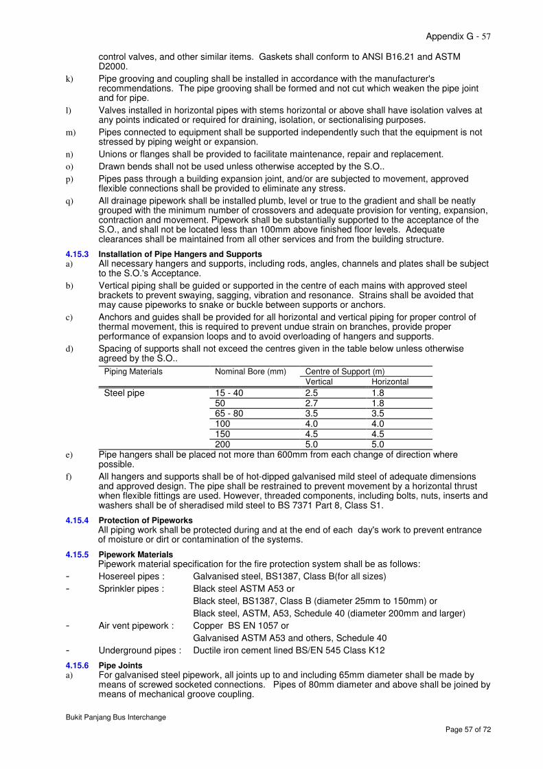
Appendix G - 57
Bukit Panjang Bus Interchange
Page 57 of 72
control valves, and other similar items. Gaskets shall conform to ANSI B16.21 and ASTM D2000.
k) Pipe grooving and coupling shall be installed in accordance with the manufacturer's recommendations. The pipe grooving shall be formed and not cut which weaken the pipe joint and for pipe.
l) Valves installed in horizontal pipes with stems horizontal or above shall have isolation valves at any points indicated or required for draining, isolation, or sectionalising purposes.
m) Pipes connected to equipment shall be supported independently such that the equipment is not stressed by piping weight or expansion.
n) Unions or flanges shall be provided to facilitate maintenance, repair and replacement.
o) Drawn bends shall not be used unless otherwise accepted by the S.O..
p) Pipes pass through a building expansion joint, and/or are subjected to movement, approved flexible connections shall be provided to eliminate any stress.
q) All drainage pipework shall be installed plumb, level or true to the gradient and shall be neatly grouped with the minimum number of crossovers and adequate provision for venting, expansion, contraction and movement. Pipework shall be substantially supported to the acceptance of the S.O., and shall not be located less than 100mm above finished floor levels. Adequate clearances shall be maintained from all other services and from the building structure.
4.15.3 Installation of Pipe Hangers and Supports a) All necessary hangers and supports, including rods, angles, channels and plates shall be subject
to the S.O.'s Acceptance.
b) Vertical piping shall be guided or supported in the centre of each mains with approved steel brackets to prevent swaying, sagging, vibration and resonance. Strains shall be avoided that may cause pipeworks to snake or buckle between supports or anchors.
c) Anchors and guides shall be provided for all horizontal and vertical piping for proper control of thermal movement, this is required to prevent undue strain on branches, provide proper performance of expansion loops and to avoid overloading of hangers and supports.
d) Spacing of supports shall not exceed the centres given in the table below unless otherwise agreed by the S.O..
Piping Materials Nominal Bore (mm) Centre of Support (m)
Vertical Horizontal
Steel pipe 15 - 40 2.5 1.8 50 2.7 1.8 65 - 80 3.5 3.5 100 4.0 4.0 150 4.5 4.5 200 5.0 5.0
e) Pipe hangers shall be placed not more than 600mm from each change of direction where possible.
f) All hangers and supports shall be of hot-dipped galvanised mild steel of adequate dimensions and approved design. The pipe shall be restrained to prevent movement by a horizontal thrust when flexible fittings are used. However, threaded components, including bolts, nuts, inserts and washers shall be of sheradised mild steel to BS 7371 Part 8, Class S1.
4.15.4 Protection of Pipeworks All piping work shall be protected during and at the end of each day's work to prevent entrance of moisture or dirt or contamination of the systems.
4.15.5 Pipework Materials Pipework material specification for the fire protection system shall be as follows:
- Hosereel pipes : Galvanised steel, BS1387, Class B(for all sizes)
- Sprinkler pipes : Black steel ASTM A53 or
Black steel, BS1387, Class B (diameter 25mm to 150mm) or
Black steel, ASTM, A53, Schedule 40 (diameter 200mm and larger)
- Air vent pipework : Copper BS EN 1057 or
Galvanised ASTM A53 and others, Schedule 40
- Underground pipes : Ductile iron cement lined BS/EN 545 Class K12
4.15.6 Pipe Joints a) For galvanised steel pipework, all joints up to and including 65mm diameter shall be made by
means of screwed socketed connections. Pipes of 80mm diameter and above shall be joined by means of mechanical groove coupling.
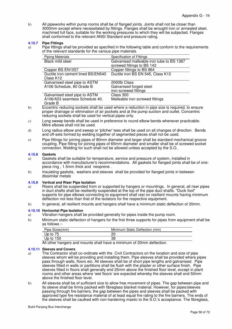
Appendix G - 58
Bukit Panjang Bus Interchange
Page 58 of 72
b) All pipeworks within pump rooms shall be of flanged joints. Joints shall not be closer than 3000mm except where necessitated by fittings. Flanges shall be wrought iron or annealed steel, machined full face, suitable for the working pressures to which they will be subjected. Flanges shall conformed to the relevant ANSI Standard and pressure rating.
4.15.7 Pipe Fittings a) Pipe fittings shall be provided as specified in the following table and conform to the requirements
of the relevant standards for the various pipe materials.
Piping Materials Specification of Fittings
Black mild steel Galvanised malleable iron tube to BS 1387 screwed fittings to BS 143
Copper BS EN1057 Copper fittings to BS 864 Ductile iron cement lined BS/EN545 Class K12
Ductile iron BS EN 545, Class K12
Galvanised steel pipe to ASTM A106 Schedule, 80 Grade B
2000lb Class Galvanised forged steel iron screwed fittings
Galvanised steel pipe to ASTM A106/A53 seamless Schedule 40, Grade B
Class 300 Malleable iron screwed fittings
b) Eccentric reducing sockets shall be used where a reduction in pipe size is required, to ensure proper drainage or elimination of air pockets and at the pump suction and outlet. Concentric reducing sockets shall be used for vertical pipes only.
c) Long sweep bends shall be used in preference to round elbow bends whenever practicable. Mitre elbows shall not be used.
d) Long radius elbow and sweep or 'pitcher' tees shall be used on all changes of direction. Bends and off-sets formed by welding together of segmented pieces shall not be used.
e) Pipe fittings for joining pipes of 80mm diameter and larger shall be standard mechanical groove coupling. Pipe fitting for joining pipes of 65mm diameter and smaller shall be of screwed socket connection. Welding for such shall not be allowed unless accepted by the S.O..
4.15.8 Gaskets a) Gaskets shall be suitable for temperature, service and pressure of system, installed in
accordance with manufacturer's recommendations. All gaskets for flanged joints shall be of one-piece ring , 1.5mm thick and neoprene .
b) Insulating gaskets, washers and sleeves shall be provided for flanged joints in between dissimilar metals
4.15.9 Vertical and Riser Pipe Isolation a) Risers shall be suspended from or supported by hangers or mountings. In general, all riser pipes
in duct shafts shall be resiliently suspended at the top of the pipe duct shafts. "Duck foot" supports for pipe elbows connecting to equipment shall rest on resilient mounts having minimum deflection not less than that of the isolators for the respective equipment.
b) In general, all resilient mounts and hangers shall have a minimum static deflection of 20mm.
4.15.10 Horizontal Pipe Isolation a) Vibration hangers shall be provided generally for pipes inside the pump room.
b) Minimum static deflection of hangers for the first three supports for pipes from equipment shall be as follows :-
Pipe Sizes(mm) Minimum Static Deflection (mm)
Up to 75 20 Up to 150 38
All other hangers and mounts shall have a minimum of 20mm deflection.
4.15.11 Sleeves and Covers a) The Contractor shall co-ordinate with the Civil Contractors on the location and size of pipe
sleeves whom will be providing and installing them. Pipe sleeves shall be provided where pipes pass through walls, floors etc. All sleeves shall be of short pipe lengths and galvanised. Pipe sleeves fitted in walls or partitions shall be flush with the plaster or other surface finish. Pipe sleeves fitted in floors shall generally end 25mm above the finished floor level, except in plant rooms and other areas where ‘wet floors' are expected whereby the sleeves shall end 50mm above the finished floor level.
b) All sleeves shall be of sufficient size to allow free movement of pipes. The gap between pipe and its sleeve shall be firmly packed with fibreglass blanket material. However, for pipes/sleeves passing through fire barriers, the gap between the pipes and sleeves shall be packed with approved type fire resistance material of at least equal fire rating to the fire barriers. The ends of the sleeves shall be caulked with non-hardening mastic to the S.O.'s acceptance. The fibreglass,
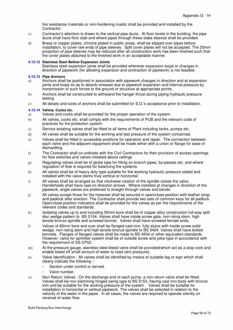
Appendix G - 59
Bukit Panjang Bus Interchange
Page 59 of 72
fire resistance materials or non-hardening mastic shall be provided and installed by the Contractor.
c) Contractor's attention is drawn to the vertical pipe ducts. At floor levels in the building, the pipe ducts shall have floor slab and where pipes through these slabs sleeves shall be provided.
d) Brass or copper plates, chrome plated in public areas, shall be slipped over pipes before installation, to cover raw ends of pipe sleeves. Split cover plates will not be accepted. The 20mm projection of pipe sleeves may be reduced after all construction work has been finished such that the cover plates attached to the finished work in an acceptable manner.
4.15.12 Stainless Steel Bellow Expansion Joints Stainless steel expansion joints shall be provided wherever expansion loops or changes in direction of pipework (for allowing expansion and contraction of pipework) is not feasible.
4.15.13 Pipe Anchors a) Anchors shall be positioned in association with pipework changes in direction and at expansion
joints and loops so as to absorb stresses due to pipework expansion and internal pressure by transmission of such forces to the ground or structure at appropriate points.
b) Anchors shall be constructed to withstand the hanger thrust during piping hydraulic pressure testing.
c) All details and sizes of anchors shall be submitted for S.O.'s acceptance prior to installation.
4.15.14 Valves, Cocks etc. a) Valves and cocks shall be provided for the proper operation of the system.
b) All valves, cocks etc. shall comply with the requirements of PUB and the relevant code of practices for fire protection system.
c) Service isolating valves shall be fitted to all items of Plant including tanks, pumps etc.
d) All valves shall be suitable for the working and test pressure of the system concerned.
e) Valves shall be fitted in accessible positions for operation and repair. The connection between each valve and the adjacent equipment shall be made either with a union or flange for ease of dismantling.
f) The Contractor shall co-ordinate with the Civil Contractors for their provision of access openings for flow switches and valves installed above ceilings
g) Regulating valves shall be of globe type for fitting on branch pipes, by-passes etc. and where regulation of flow is required for balancing the systems.
h) All valves shall be of heavy duty type suitable for the working hydraulic pressure stated and installed with the valve stems truly vertical or horizontal.
i) All valves shall be arranged so that clockwise rotation of the spindle closes the valve. Handwheels shall have cast-on direction arrows. Where installed at changes in direction of the pipework, angle valves are preferred to straight through valves and bends.
j) All valves except those for the hosereel shall be secured in open/close position with leather strap and padlock after erection. The Contractor shall provide two sets of common keys for all padlock. Open/close position indicators shall be provided for the valves as per the requirements of the relevant codes and standards.
k) Isolating valves up to and including 50mm bore shall be of copper alloy construction full-way split disc wedge pattern to BS 5154. Valves shall have inside screw gate, non-rising stem, high tensile bronze spindle and screwed bonnet. Valves shall have screwed female ends.
l) Valves of 65mm bore and over shall be flanged cast-iron, fully sluice with inside screw solid wedge, non-rising stem and high tensile bronze spindle to BS 3464. Valves shall have bolted bonnets. Flanges of flanged valves shall be made to BS 4504 or other equivalent standards. However, valve for sprinkler system shall be of outside screw and yoke type in accordance with the requirement of SS CP52.
m) At the pressure gauge, stainless steel bleed valve shall be provided(which act as a stop cock and enable bleed off small amount of water to read zero pressure).
n) Valve Identification : All valves shall be identified by means of suitable tag or sign which shall clearly indicate the following :-
- Section under control or served.
- Valve number.
o) Non-Return Valves : On the discharge end of each pump, a non-return valve shall be fitted. Valves shall be non-slamming hinged swing type to BS 5153, having cast iron body with bronze trim and be suitable for the working pressure of the system. Valves shall be suitable for installation in horizontal or vertical pipework. The valves shall be selected in relation to the velocity of the water in the pipes. In all cases, the valves are required to operate silently on reversal of water flow.
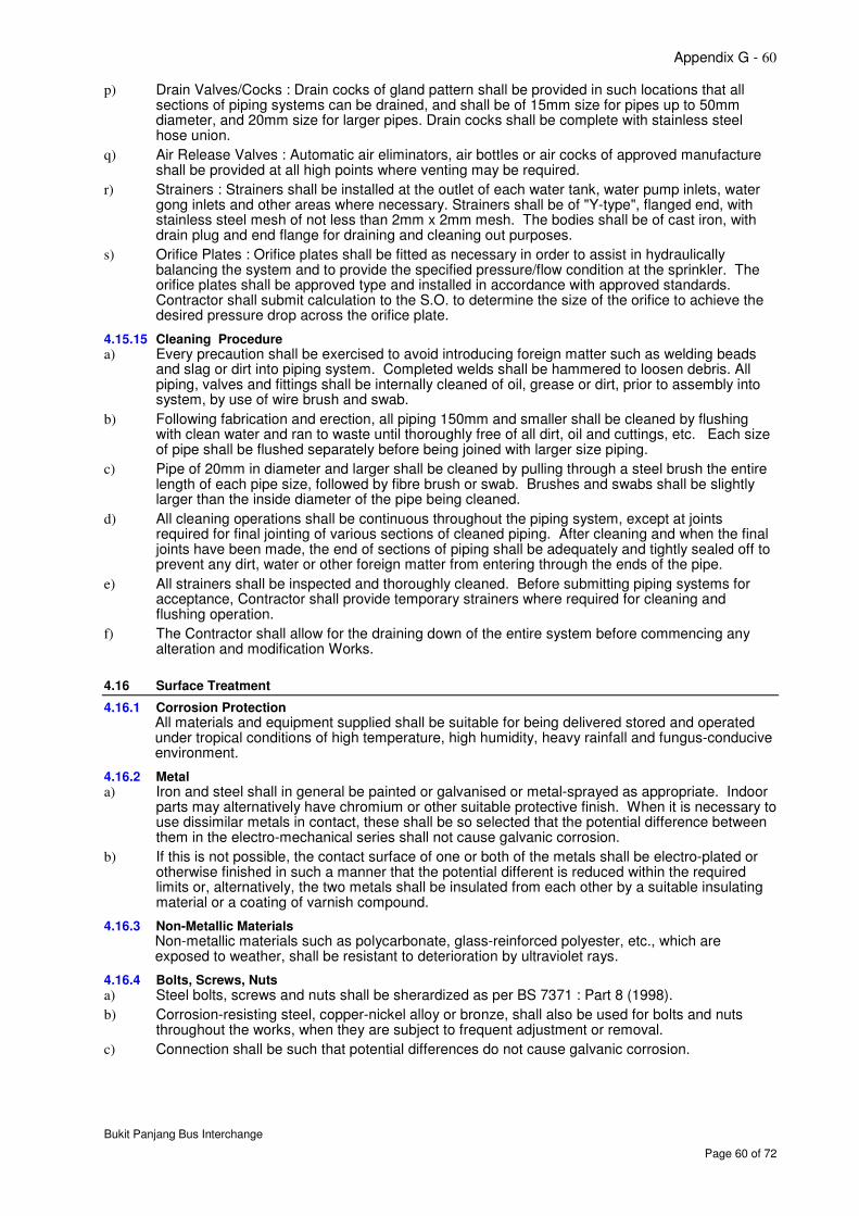
Appendix G - 60
Bukit Panjang Bus Interchange
Page 60 of 72
p) Drain Valves/Cocks : Drain cocks of gland pattern shall be provided in such locations that all sections of piping systems can be drained, and shall be of 15mm size for pipes up to 50mm diameter, and 20mm size for larger pipes. Drain cocks shall be complete with stainless steel hose union.
q) Air Release Valves : Automatic air eliminators, air bottles or air cocks of approved manufacture shall be provided at all high points where venting may be required.
r) Strainers : Strainers shall be installed at the outlet of each water tank, water pump inlets, water gong inlets and other areas where necessary. Strainers shall be of "Y-type", flanged end, with stainless steel mesh of not less than 2mm x 2mm mesh. The bodies shall be of cast iron, with drain plug and end flange for draining and cleaning out purposes.
s) Orifice Plates : Orifice plates shall be fitted as necessary in order to assist in hydraulically balancing the system and to provide the specified pressure/flow condition at the sprinkler. The orifice plates shall be approved type and installed in accordance with approved standards. Contractor shall submit calculation to the S.O. to determine the size of the orifice to achieve the desired pressure drop across the orifice plate.
4.15.15 Cleaning Procedure a) Every precaution shall be exercised to avoid introducing foreign matter such as welding beads
and slag or dirt into piping system. Completed welds shall be hammered to loosen debris. All piping, valves and fittings shall be internally cleaned of oil, grease or dirt, prior to assembly into system, by use of wire brush and swab.
b) Following fabrication and erection, all piping 150mm and smaller shall be cleaned by flushing with clean water and ran to waste until thoroughly free of all dirt, oil and cuttings, etc. Each size of pipe shall be flushed separately before being joined with larger size piping.
c) Pipe of 20mm in diameter and larger shall be cleaned by pulling through a steel brush the entire length of each pipe size, followed by fibre brush or swab. Brushes and swabs shall be slightly larger than the inside diameter of the pipe being cleaned.
d) All cleaning operations shall be continuous throughout the piping system, except at joints required for final jointing of various sections of cleaned piping. After cleaning and when the final joints have been made, the end of sections of piping shall be adequately and tightly sealed off to prevent any dirt, water or other foreign matter from entering through the ends of the pipe.
e) All strainers shall be inspected and thoroughly cleaned. Before submitting piping systems for acceptance, Contractor shall provide temporary strainers where required for cleaning and flushing operation.
f) The Contractor shall allow for the draining down of the entire system before commencing any alteration and modification Works.
4.16 Surface Treatment
4.16.1 Corrosion Protection All materials and equipment supplied shall be suitable for being delivered stored and operated under tropical conditions of high temperature, high humidity, heavy rainfall and fungus-conducive environment.
4.16.2 Metal a) Iron and steel shall in general be painted or galvanised or metal-sprayed as appropriate. Indoor
parts may alternatively have chromium or other suitable protective finish. When it is necessary to use dissimilar metals in contact, these shall be so selected that the potential difference between them in the electro-mechanical series shall not cause galvanic corrosion.
b) If this is not possible, the contact surface of one or both of the metals shall be electro-plated or otherwise finished in such a manner that the potential different is reduced within the required limits or, alternatively, the two metals shall be insulated from each other by a suitable insulating material or a coating of varnish compound.
4.16.3 Non-Metallic Materials Non-metallic materials such as polycarbonate, glass-reinforced polyester, etc., which are exposed to weather, shall be resistant to deterioration by ultraviolet rays.
4.16.4 Bolts, Screws, Nuts a) Steel bolts, screws and nuts shall be sherardized as per BS 7371 : Part 8 (1998).
b) Corrosion-resisting steel, copper-nickel alloy or bronze, shall also be used for bolts and nuts throughout the works, when they are subject to frequent adjustment or removal.
c) Connection shall be such that potential differences do not cause galvanic corrosion.
Appendix G - 61
Bukit Panjang Bus Interchange
Page 61 of 72
4.16.5 Painting
4.16.5.1 Metal Items and Structures
All surfaces to be painted shall be thoroughly cleaned of all dirt, dust, grease, oil and rust before the paint application.
4.16.5.2 Priming
The primer serves as a basic protection against corrosion and additionally to guarantee adherence between surface and the finish paint. Zinc-epoxy, zinc-chromate or red lead primers are suggested for this purpose.
4.16.5.3 Finishing
a) Two finish coatings of minimum 0.05mm thickness shall be applied to painted surfaces. The proposed materials (epoxy resin base preferred), coat thickness, colours, etc. are subject to the Authority’s approval.
b) For items that are not painted, the zinc coating shall have minimum 500g/sq.m of coated surface.
c) Any electrical boxes or other housing enclosures outdoors shall be of weather proof type.
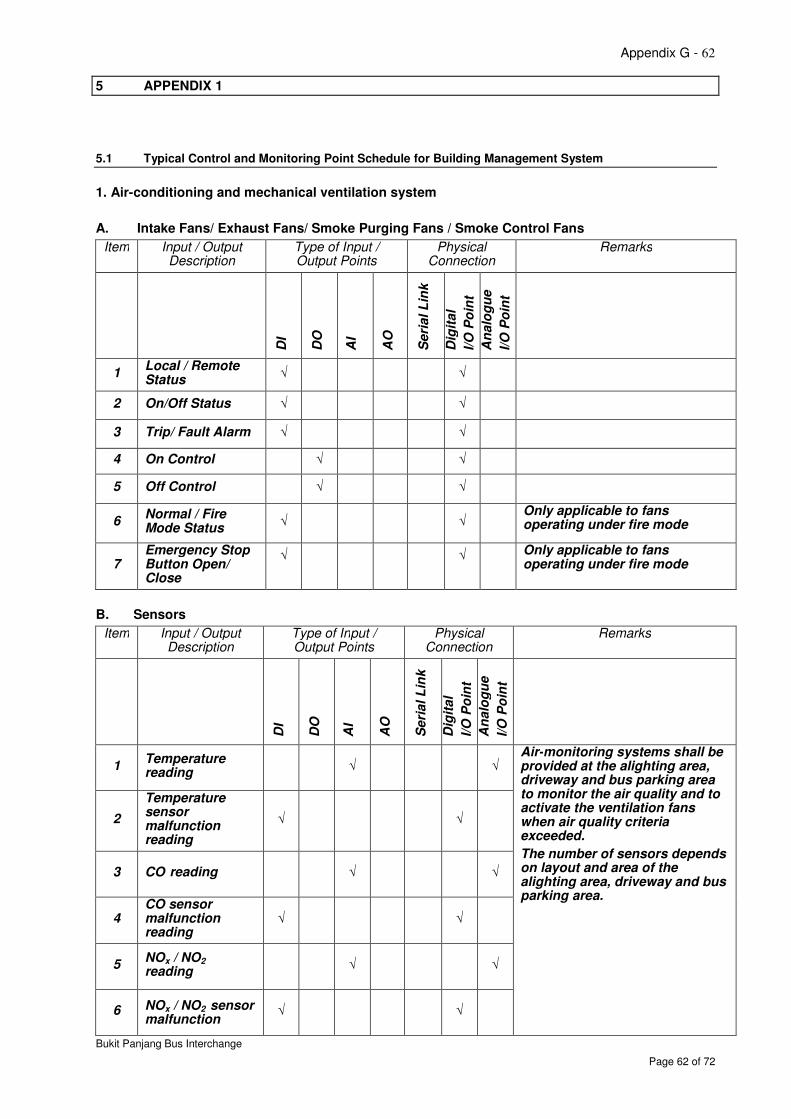
Appendix G - 62
Bukit Panjang Bus Interchange
Page 62 of 72
5 APPENDIX 1
5.1 Typical Control and Monitoring Point Schedule for Building Management System
1. Air-conditioning and mechanical ventilation system
A. Intake Fans/ Exhaust Fans/ Smoke Purging Fans / Smoke Control Fans
Item Input / Output Description
Type of Input / Output Points
Physical Connection
Remarks
D
I
DO
AI
AO
Seri
al L
ink
Dig
ital
I/O
Po
int
An
alo
gu
e
I/O
Po
int
1 Local / Remote Status
√
√
2 On/Off Status √ √
3 Trip/ Fault Alarm √ √
4 On Control √ √
5 Off Control √ √
6 Normal / Fire Mode Status
√
√ Only applicable to fans operating under fire mode
7 Emergency Stop Button Open/ Close
√
√
Only applicable to fans operating under fire mode
B. Sensors
Item Input / Output Description
Type of Input / Output Points
Physical Connection
Remarks
DI
DO
AI
AO
Seri
al L
ink
Dig
ital
I/O
Po
int
An
alo
gu
e
I/O
Po
int
1 Temperature reading
√ √ Air-monitoring systems shall be provided at the alighting area, driveway and bus parking area to monitor the air quality and to activate the ventilation fans when air quality criteria exceeded.
The number of sensors depends on layout and area of the alighting area, driveway and bus parking area.
2
Temperature sensor malfunction reading
√ √
3 CO reading √ √
4 CO sensor malfunction reading
√ √
5 NOx / NO2 reading
√ √
6 NOx / NO2 sensor malfunction
√ √
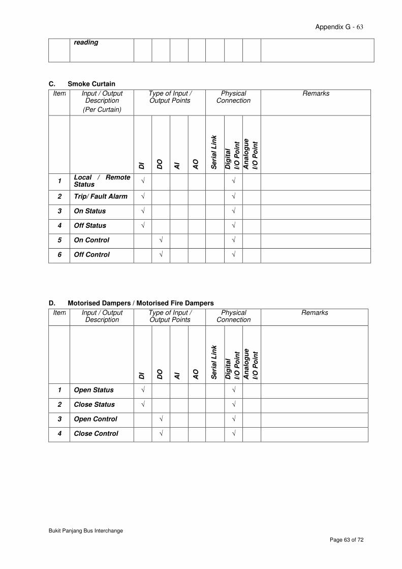
Appendix G - 63
Bukit Panjang Bus Interchange
Page 63 of 72
reading
C. Smoke Curtain
Item Input / Output Description
(Per Curtain)
Type of Input / Output Points
Physical Connection
Remarks
DI
DO
AI
AO
Seri
al L
ink
Dig
ital
I/O
Po
int
An
alo
gu
e
I/O
Po
int
1 Local / Remote Status
√
√
2 Trip/ Fault Alarm √ √
3 On Status √ √
4 Off Status √ √
5 On Control √ √
6 Off Control √ √
D. Motorised Dampers / Motorised Fire Dampers
Item Input / Output Description
Type of Input / Output Points
Physical Connection
Remarks
DI
DO
AI
AO
Seri
al L
ink
Dig
ital
I/O
Po
int
An
alo
gu
e
I/O
Po
int
1 Open Status √ √
2 Close Status √ √
3 Open Control √ √
4 Close Control √ √
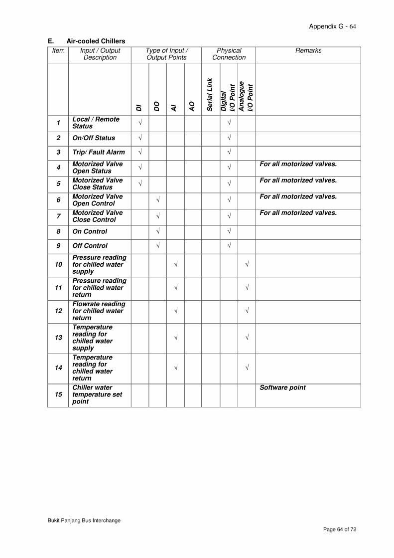
Appendix G - 64
Bukit Panjang Bus Interchange
Page 64 of 72
E. Air-cooled Chillers
Item Input / Output Description
Type of Input / Output Points
Physical Connection
Remarks
DI
DO
AI
AO
Seri
al L
ink
Dig
ital
I/O
Po
int
An
alo
gu
e
I/O
Po
int
1 Local / Remote Status
√
√
2 On/Off Status √ √
3 Trip/ Fault Alarm √ √
4 Motorized Valve Open Status
√
√ For all motorized valves.
5 Motorized Valve Close Status
√
√ For all motorized valves.
6 Motorized Valve Open Control
√
√
For all motorized valves.
7 Motorized Valve Close Control
√
√
For all motorized valves.
8 On Control √ √
9 Off Control √ √
10 Pressure reading for chilled water supply
√
√
11 Pressure reading for chilled water return
√
√
12 Flowrate reading for chilled water return
√
√
13
Temperature reading for chilled water supply
√
√
14
Temperature reading for chilled water return
√
√
15 Chiller water temperature set point
Software point
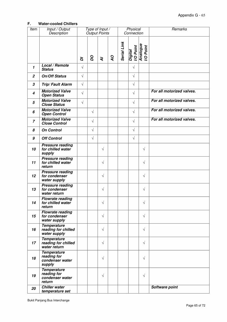
Appendix G - 65
Bukit Panjang Bus Interchange
Page 65 of 72
F. Water-cooled Chillers
Item Input / Output Description
Type of Input / Output Points
Physical Connection
Remarks
DI
DO
AI
AO
Seri
al L
ink
Dig
ital
I/O
Po
int
An
alo
gu
e
I/O
Po
int
1 Local / Remote Status
√
√
2 On/Off Status √ √
3 Trip/ Fault Alarm √ √
4 Motorized Valve Open Status
√ √ For all motorized valves.
5 Motorized Valve Close Status
√ √ For all motorized valves.
6 Motorized Valve Open Control
√
√
For all motorized valves.
7 Motorized Valve Close Control
√
√
For all motorized valves.
8 On Control √ √
9 Off Control √ √
10 Pressure reading for chilled water supply
√
√
11 Pressure reading for chilled water return
√
√
12 Pressure reading for condenser water supply
√
√
13 Pressure reading for condenser water return
√
√
14 Flowrate reading for chilled water return
√
√
15 Flowrate reading for condenser water supply
√
√
16 Temperature reading for chilled water supply
√
√
17 Temperature reading for chilled water return
√
√
18
Temperature reading for condenser water supply
√
√
19
Temperature reading for condenser water return
√
√
20 Chiller water temperature set
Software point
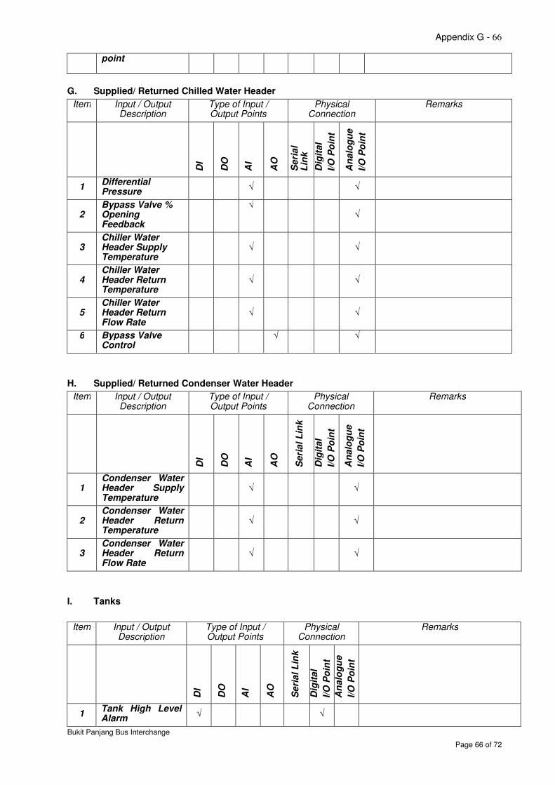
Appendix G - 66
Bukit Panjang Bus Interchange
Page 66 of 72
point
G. Supplied/ Returned Chilled Water Header
Item Input / Output Description
Type of Input / Output Points
Physical Connection
Remarks
DI
DO
AI
AO
Seri
al
Lin
k
Dig
ital
I/O
Po
int
An
alo
gu
e
I/O
Po
int
1 Differential Pressure
√
√
2 Bypass Valve % Opening Feedback
√ √
3 Chiller Water Header Supply Temperature
√ √
4 Chiller Water Header Return Temperature
√ √
5 Chiller Water Header Return Flow Rate
√ √
6 Bypass Valve Control
√ √
H. Supplied/ Returned Condenser Water Header
Item Input / Output Description
Type of Input / Output Points
Physical Connection
Remarks
DI
DO
AI
AO
Seri
al L
ink
Dig
ital
I/O
Po
int
An
alo
gu
e
I/O
Po
int
1 Condenser Water Header Supply Temperature
√ √
2 Condenser Water Header Return Temperature
√ √
3 Condenser Water Header Return Flow Rate
√ √
I. Tanks
Item Input / Output Description
Type of Input / Output Points
Physical Connection
Remarks
DI
DO
AI
AO
Seri
al L
ink
Dig
ital
I/O
Po
int
An
alo
gu
e
I/O
Po
int
1 Tank High Level Alarm
√ √
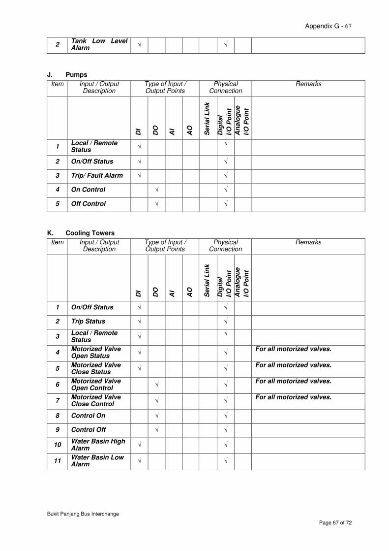
Appendix G - 67
Bukit Panjang Bus Interchange
Page 67 of 72
2 Tank Low Level Alarm
√ √
J. Pumps
Item Input / Output Description
Type of Input / Output Points
Physical Connection
Remarks
DI
DO
AI
AO
Seri
al L
ink
Dig
ital
I/O
Po
int
An
alo
gu
e
I/O
Po
int
1 Local / Remote Status
√
√
2 On/Off Status √ √
3 Trip/ Fault Alarm √ √
4 On Control √ √
5 Off Control √ √
K. Cooling Towers
Item Input / Output Description
Type of Input / Output Points
Physical Connection
Remarks
DI
DO
AI
AO
Seri
al L
ink
Dig
ital
I/O
Po
int
An
alo
gu
e
I/O
Po
int
1 On/Off Status √ √
2 Trip Status √ √
3 Local / Remote Status
√
√
4 Motorized Valve Open Status
√ √ For all motorized valves.
5 Motorized Valve Close Status
√ √ For all motorized valves.
6 Motorized Valve Open Control
√
√
For all motorized valves.
7 Motorized Valve Close Control
√
√
For all motorized valves.
8 Control On √ √
9 Control Off √ √
10 Water Basin High Alarm
√
√
11 Water Basin Low Alarm
√
√
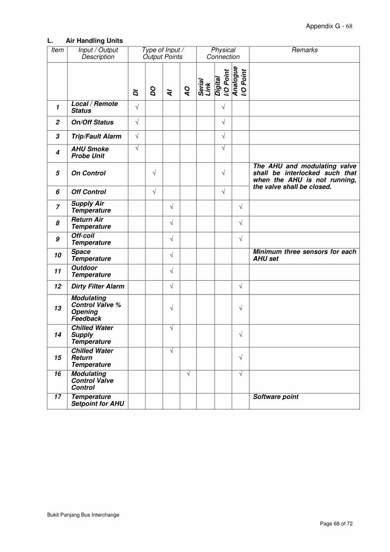
Appendix G - 68
Bukit Panjang Bus Interchange
Page 68 of 72
L. Air Handling Units
Item Input / Output Description
Type of Input / Output Points
Physical Connection
Remarks
DI
DO
AI
AO
Seri
al
Lin
k
Dig
ital
I/O
Po
int
An
alo
gu
e
I/O
Po
int
1 Local / Remote Status
√
√
2 On/Off Status √ √
3 Trip/Fault Alarm √ √
4 AHU Smoke Probe Unit
√
√
5 On Control √
√ The AHU and modulating valve shall be interlocked such that when the AHU is not running, the valve shall be closed.
6 Off Control √ √
7 Supply Air Temperature
√ √
8 Return Air Temperature
√ √
9 Off-coil Temperature
√ √
10 Space Temperature
√ Minimum three sensors for each AHU set
11 Outdoor Temperature
√
12 Dirty Filter Alarm √ √
13
Modulating Control Valve % Opening Feedback
√ √
14 Chilled Water Supply Temperature
√
√
15 Chilled Water Return Temperature
√
√
16 Modulating Control Valve Control
√ √
17 Temperature Setpoint for AHU
Software point
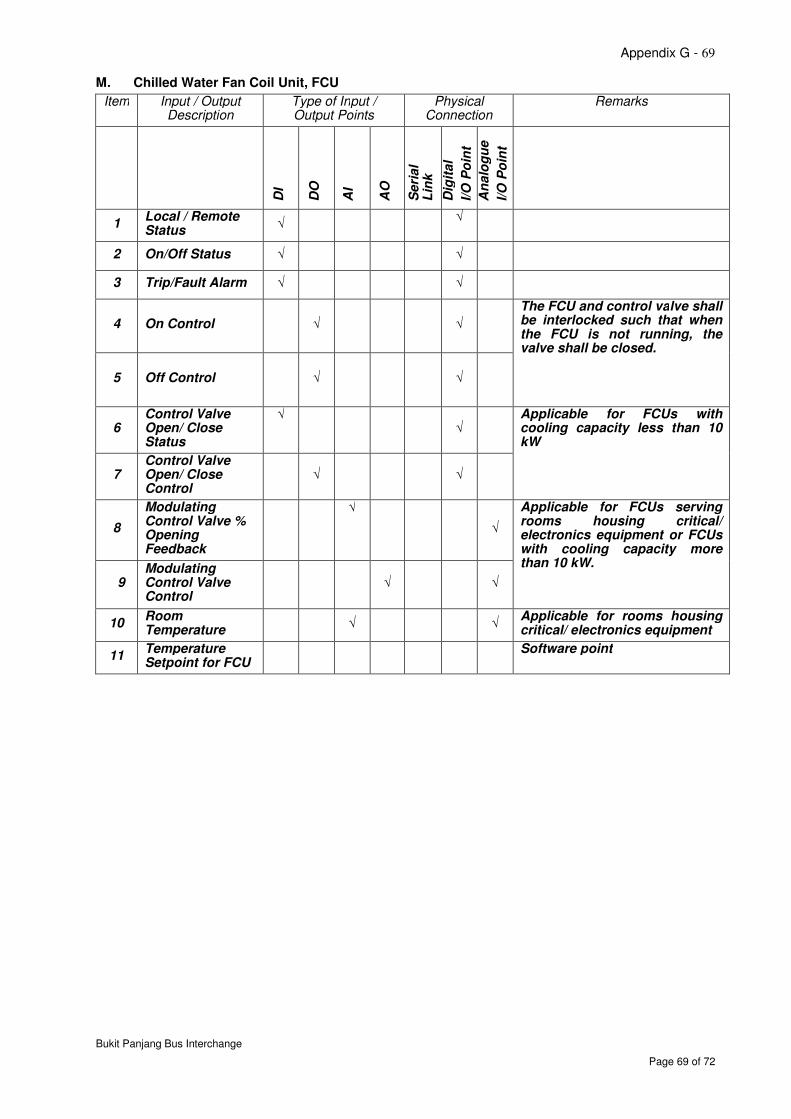
Appendix G - 69
Bukit Panjang Bus Interchange
Page 69 of 72
M. Chilled Water Fan Coil Unit, FCU
Item Input / Output Description
Type of Input / Output Points
Physical Connection
Remarks
DI
DO
AI
AO
Seri
al
Lin
k
Dig
ital
I/O
Po
int
An
alo
gu
e
I/O
Po
int
1 Local / Remote Status
√
√
2 On/Off Status √ √
3 Trip/Fault Alarm √ √
4 On Control √
√
The FCU and control valve shall be interlocked such that when the FCU is not running, the valve shall be closed.
5 Off Control √
√
6 Control Valve Open/ Close Status
√
√
Applicable for FCUs with cooling capacity less than 10 kW
7 Control Valve Open/ Close Control
√
√
8
Modulating Control Valve % Opening Feedback
√
√
Applicable for FCUs serving rooms housing critical/ electronics equipment or FCUs with cooling capacity more than 10 kW.
9 Modulating Control Valve Control
√ √
10 Room Temperature
√ √ Applicable for rooms housing critical/ electronics equipment
11 Temperature Setpoint for FCU
Software point
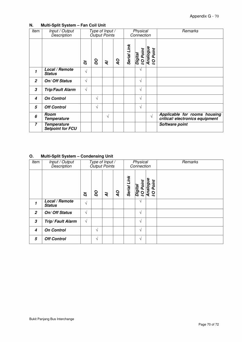
Appendix G - 70
Bukit Panjang Bus Interchange
Page 70 of 72
N. Multi-Split System – Fan Coil Unit
Item Input / Output Description
Type of Input / Output Points
Physical Connection
Remarks
DI
DO
AI
AO
Seri
al L
ink
Dig
ital
I/O
Po
int
An
alo
gu
e
I/O
Po
int
1 Local / Remote Status
√
√
2 On/ Off Status √ √
3 Trip/Fault Alarm √ √
4 On Control √ √
5 Off Control √ √
6 Room Temperature
√ √ Applicable for rooms housing critical/ electronics equipment
7 Temperature Setpoint for FCU
Software point
O. Multi-Split System – Condensing Unit
Item Input / Output Description
Type of Input / Output Points
Physical Connection
Remarks
DI
DO
AI
AO
Seri
al L
ink
Dig
ital
I/O
Po
int
An
alo
gu
e
I/O
Po
int
1 Local / Remote Status
√
√
2 On/ Off Status √ √
3 Trip/ Fault Alarm √ √
4 On Control √ √
5 Off Control √ √
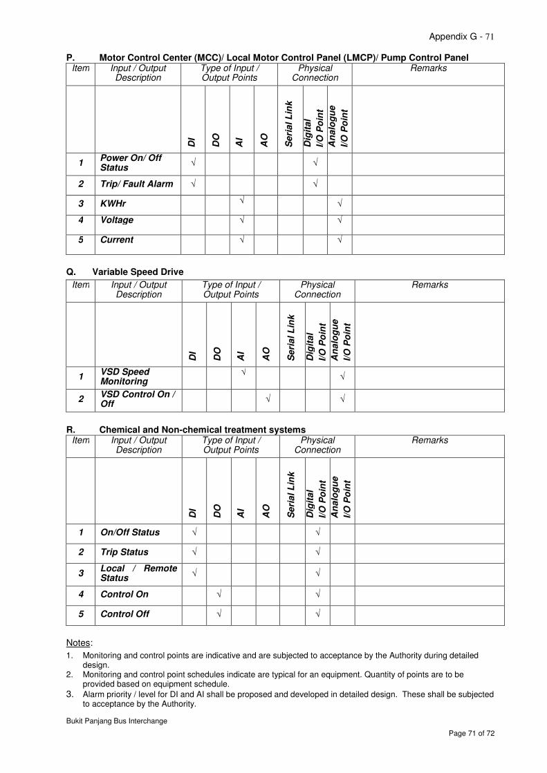
Appendix G - 71
Bukit Panjang Bus Interchange
Page 71 of 72
P. Motor Control Center (MCC)/ Local Motor Control Panel (LMCP)/ Pump Control Panel Item Input / Output
Description Type of Input / Output Points
Physical Connection
Remarks
DI
DO
AI
AO
Seri
al L
ink
Dig
ital
I/O
Po
int
An
alo
gu
e
I/O
Po
int
1 Power On/ Off Status
√
√
2 Trip/ Fault Alarm √ √
3 KWHr √ √
4 Voltage √ √
5 Current √ √
Q. Variable Speed Drive
Item Input / Output Description
Type of Input / Output Points
Physical Connection
Remarks
DI
DO
AI
AO
Seri
al L
ink
Dig
ital
I/O
Po
int
An
alo
gu
e
I/O
Po
int
1 VSD Speed Monitoring
√
√
2 VSD Control On / Off
√ √
R. Chemical and Non-chemical treatment systems Item Input / Output
Description Type of Input / Output Points
Physical Connection
Remarks
DI
DO
AI
AO
Seri
al L
ink
Dig
ital
I/O
Po
int
An
alo
gu
e
I/O
Po
int
1 On/Off Status √ √
2 Trip Status √ √
3 Local / Remote Status
√ √
4 Control On √ √
5 Control Off √ √
Notes:
1. Monitoring and control points are indicative and are subjected to acceptance by the Authority during detailed design.
2. Monitoring and control point schedules indicate are typical for an equipment. Quantity of points are to be provided based on equipment schedule.
3. Alarm priority / level for DI and AI shall be proposed and developed in detailed design. These shall be subjected to acceptance by the Authority.

Appendix G - 72
Bukit Panjang Bus Interchange
Page 72 of 72