Embed Size (px)
Citation preview
MECH3005 – Building Serviceshttp://www.hku.hk/bse/mech3005/
Dr. Sam C M HuiDepartment of Mechanical Engineering
The University of Hong KongE-mail: [email protected]
Air-side Systems
Air Conditioning & Refrigeration:

Contents
• Fundamental HVAC Concepts
• Air Handling Units
• Air System Basics• Fan-duct systems• Fan modulation & combinations• Year-round operation & economizers• Fan energy use & outdoor air

Fundamental HVAC Concepts
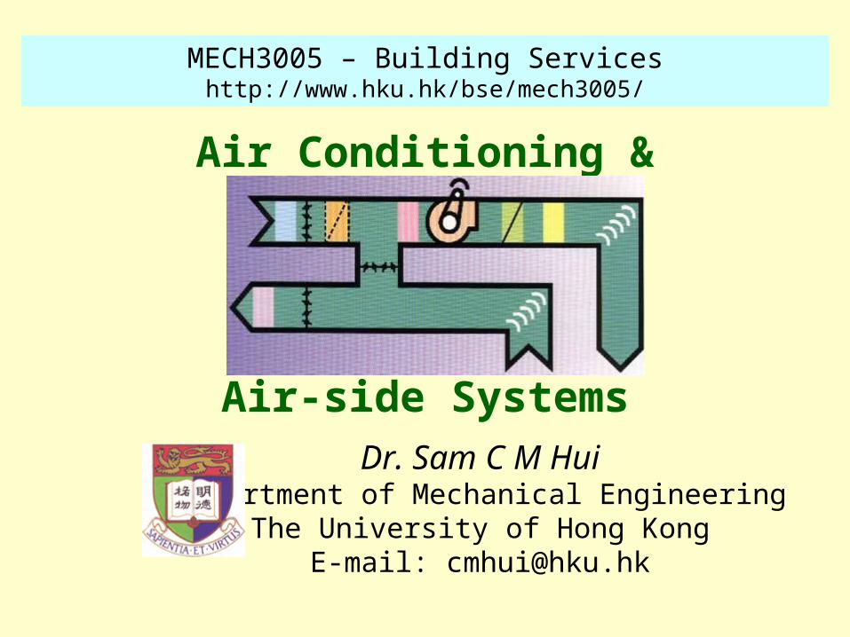
• Five subsystems or loops of HVAC• Air-side• Chilled water• Refrigeration equipment• Heat rejection• Controls

33 oC, 28 oC
27 oC33 oC
25 oC
Conditioned space
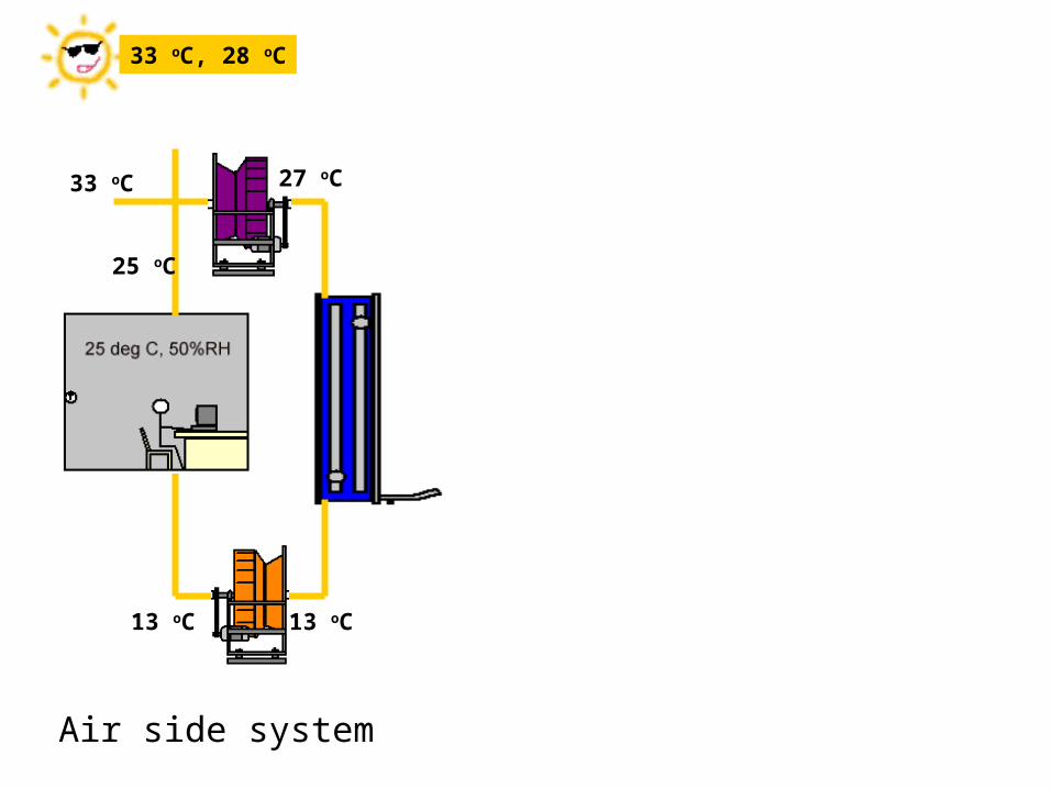
13 oC 13 oC
33 oC, 28 oC
27 oC33 oC
25 oC
Air side system

13 oC 13 oC
12 oC
7 oC
33 oC, 28 oC
7 oC
12 oC
27 oC33 oC
25 oC
Chilled watersystem

13 oC 13 oC
12 oC
7 oC 3 oC38 oC
49 oC10 oC
33 oC, 28 oC
7 oC
12 oC
27 oC33 oC
25 oC
Refrigerationequipment

13 oC 13 oC
12 oC
7 oC 3 oC38 oC
49 oC10 oC
35 oC
29 oC
33 oC, 28 oC
7 oC
12 oC
29 oC
35 oC
27 oC33 oC
25 oC
Heat rejection

13 oC 13 oC
12 oC
7 oC 3 oC38 oC
49 oC10 oC
35 oC
29 oC
33 oC, 28 oC
7 oC
12 oC
29 oC
35 oC
27 oC33 oC
25 oC
Control Loop

Individual room air-conditioning system

Primary air fan coil unit system

Dual duct system
What type of air conditioning system it is?

Air Handling Units
• Terminal unit or device• Such as fan coil units, VAV boxes
• Air handling unit (AHU)• Primary equipment of the air system• Handle & condition the air, control it to a required
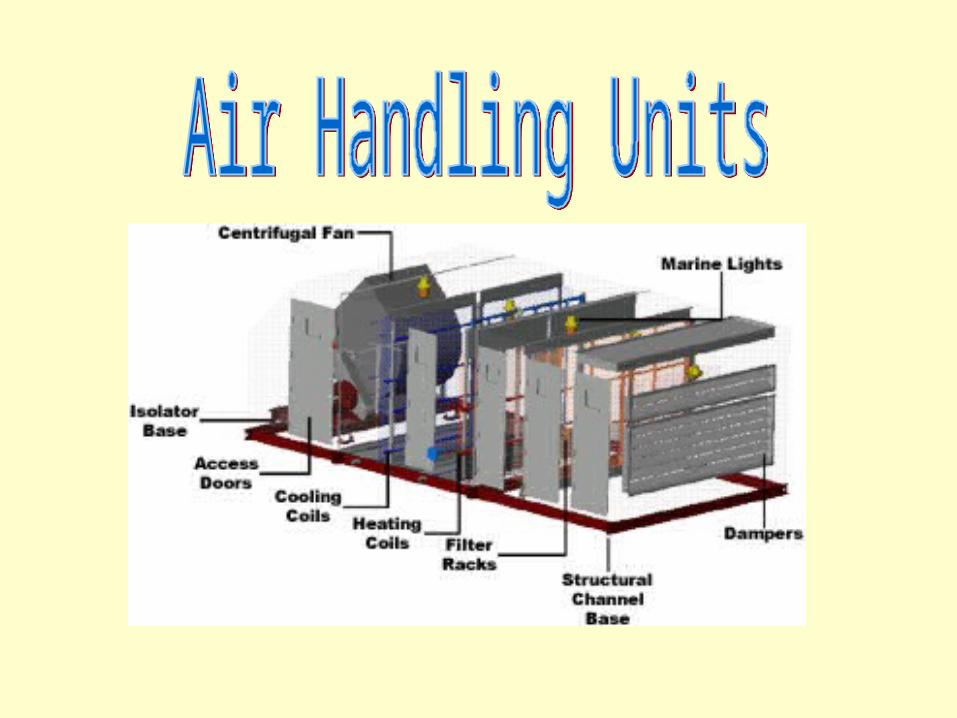
state, and transport it• Basic components:
• Supply fan, water cooling coil, filters, mixing box, dampers, controls & outer casing
• A return or relief fan is optional, so as a humidifier

Air Handling Units
• Types of AHUs:• Horizontal or vertical• Draw-through or blow through• Factory-fabricated and field built-up• Rooftop and indoor• Make-up (primary) air • Recirculating


Air Handling Units
• Package units• A self-contained air conditioner• Equipped with a DX (direct expansion) coil• “Air handler”: the portion inside that handles air
• Rooftop package units• Gas heating / electric cooling• Electric heating / electric cooling• Heat pump system


Air Handling Units
• Indoor package units• Factory-assembly unit installed in a fan room or
machinery room• Floor-mounted or ceiling-mounted• Cooling, cooling/heating, heat pump• Heat rejection:
• Connected to an air-cooled condenser, OR• Water-cooled condenser
• Split package units• Indoor air handler + outdoor condensing unit

Air Handling Units
• Rating conditions & minimum performance• ARI and ASHRAE standards• Rating indices:
• Energy efficiency ratio (EER)
• Seasonal EER
• Integrated part-load value (IPLV)
• Heating seasonal performance factor (HSPF)

Air Handling Units
• Coils• Indirect contact heat exchangers• Heat transfer between air flowing over the coil and
water, refrigerant, steam or brine insider the coil• Fins: extended (secondary) surfaces
• Fin spacing and density
• Water circuits• Number of water flow passages

Air Handling Units
• Direct expansion (DX) coil• Refrigerant is fed (e.g. R-22 and R-134a)• Air and refrigerant flow:
• Usually counterflow and cross flow
• Typical evaporating temperature = 3-10 oC• Condensate drain pan (to collect condensation)• Performance factors:
• Face velocity, heat transfer coefficients, air-side pressure drop, physical size

Air Handling Units
• Water cooling coils - dry-wet coil• Chilled water flowing at 4-10 oC• Brine or glycol-water at 1-4 oC• Temperature rise (typical) = 7-14 oC
• Water cooling coils - dry coil• Sensible cooling (dry); no condensation• Poorer heat transfer coefficient
• Steam heating coil

Direct expansion (DX) coil
Water cooling coil

Water heating coil
Steam heating coil

Air Handling Units
• Air filters• Air cleaning and filtration• Operating performance:
• Efficiency or effectiveness of dust removal
• Dust holding capacity
• Initial & final pressure drop
• Service life
• Types: low-, medium-, and high-efficiency filters + carbon activated filters

Air Handling Units
• Test methods of air filters• Weight arrestance test
• For low-efficiency air filters
• Atmospheric dust spot efficiency• For medium-efficiency air filters
• DOP (dioctyl phthalate) penetration and efficiency test
• For high-efficiency air filters• HEPA (high-efficiency particle air)
• ULPA (ultra-low penetration air)

Low efficiency (panel-type) Medium efficiency (bag-type)
HEPA and ULPA filters Activated carbon filter

Air Handling Units
• Humidifiers• Steam humidifiers• Air washers
• Selection of AHUs• Face velocity < 3 m/s to prevent entrained droplets• Proper size of the equipment (energy efficiency)• Medium-efficiency filter >50% dust spot eff.:
improve IAQ, prevent smudging & discoloring• Air economizer: save energy

Steam grid humidifier

Air washer
Air-side Components
• EcoAdvisor: Energy Trainer for Energy Managers: HAVC Module 1 [AV 697 E19]• HVAC components
• Distribution equipment• Air-side components
• Dampers, filters, coils, fans, ducts and plenums, terminal units, diffusers, humidifiers, dehumidifiers


Air System Basics
• Fan-duct systems• Flow resistance R, pressure drop Δp and volume flow
rate V
• Duct sections in series:
• Duct sections in parallel:
2VRp o
ns RRRR 21
np RRRR
1111
21

Air System Basics
• Fan-duct systems• Terminology
• Primary air (conditioned air or makeup air)
• Secondary air (induced space air, plenum air, or recirculating air)
• Transfer air (indoor air that moves from an adjacent area)
• System curve: volume flow vs pressure loss• System operating point

Air System Basics
• Fan Laws• Speed (n)
• Volume flow (V)
• Total pressure loss (Δp )
• Air density (ρ)
• For air systems that are geometrically & dynamically similar: (D = impeller diameter)

Air System Basics
• System effect Δpts
• Its additional total pressure loss caused by uneven or non-uniform velocity profile at the fan inlet, or at duct fittings after fan outlet
• Due to the actual inlet and outlet connections as compared with the total pressure loss of the fan test unit during laboratory ratings
Inlet Outlet

Fan system operating point & system effect

Air System Basics
• Modulation of air systems• Constant volume system
• Volume flow rate remains constant; supply temperature is raised during part load
• Variable-air-volume (VAV) system• Volume flow rate is reduced to match part load
operation
• Modulation curve

Fan modulation curve

Air System Basics
• Fan modulation methods• Damper (vary the opening of the air flow passage)
• Waste energy
• Inlet vanes (opening & angle of inlet vanes)• Low cost; less efficient than following types
• Inlet cone (peripheral area of fan impeller)• Inexpensive; for backward curved centrifugal fan
• Blade pitch (blade angle of axial fan)• Fan speed (using adjustable frequency drives)
• Most energy-efficient; but more expensive

Damper, inlet vanes & fan speed modulation

Air System Basics
• Fan combinations in AHUs• Supply and exhaust fan/barometric damper
• Used when no return duct or low return pressure loss
• Barometric relief damper: to prevent excessive high space pressure
• Suitable for systems w/ no air economizer mode & a low pressure drop in return system
Supply and exhaust fans
Air System Basics
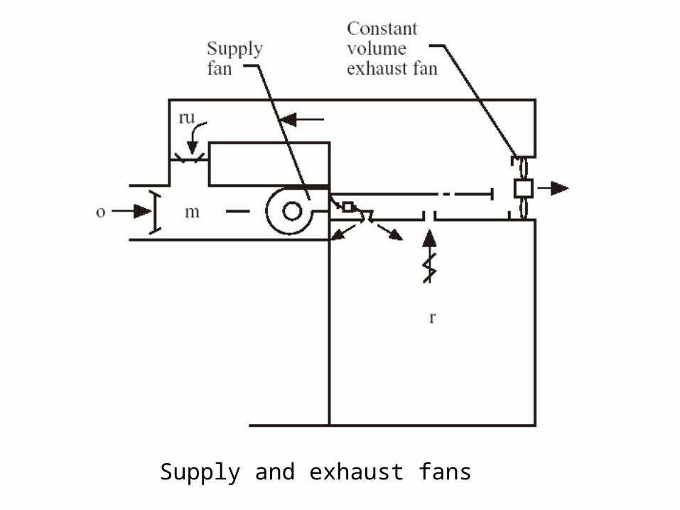
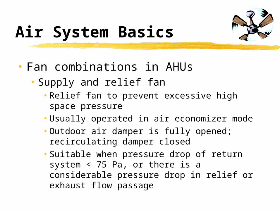
• Fan combinations in AHUs• Supply and relief fan
• Relief fan to prevent excessive high space pressure
• Usually operated in air economizer mode
• Outdoor air damper is fully opened; recirculating damper closed
• Suitable when pressure drop of return system < 75 Pa, or there is a considerable pressure drop in relief or exhaust flow passage
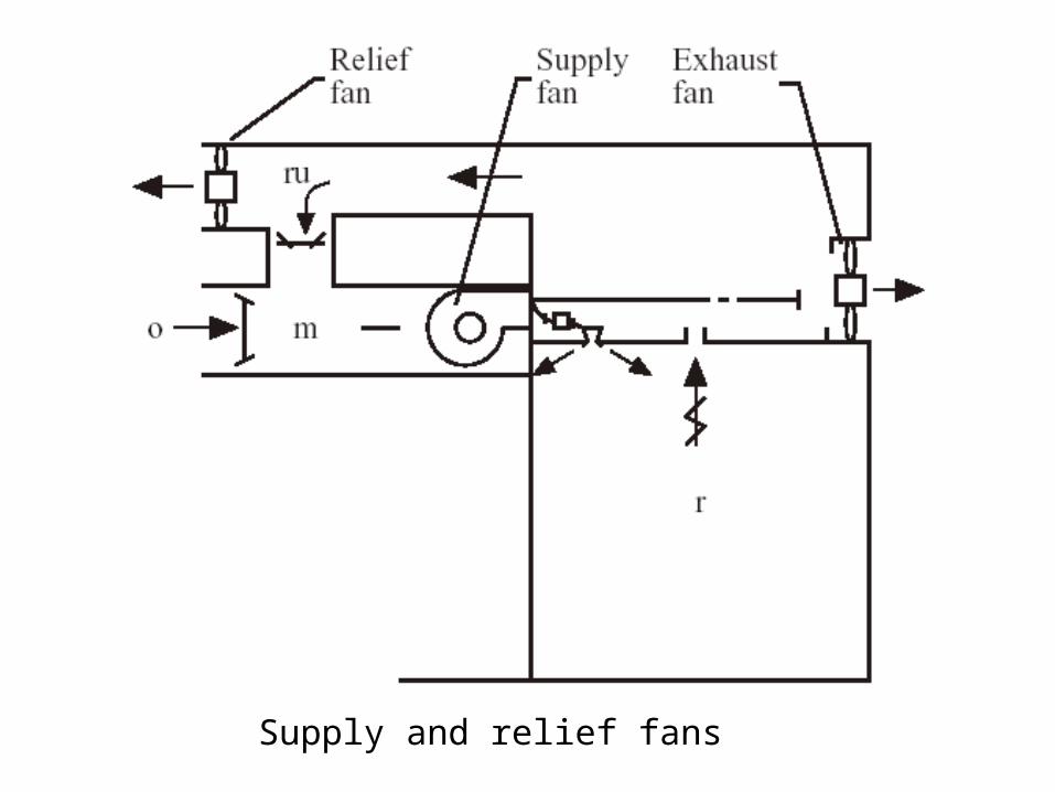
Supply and relief fans
Air System Basics
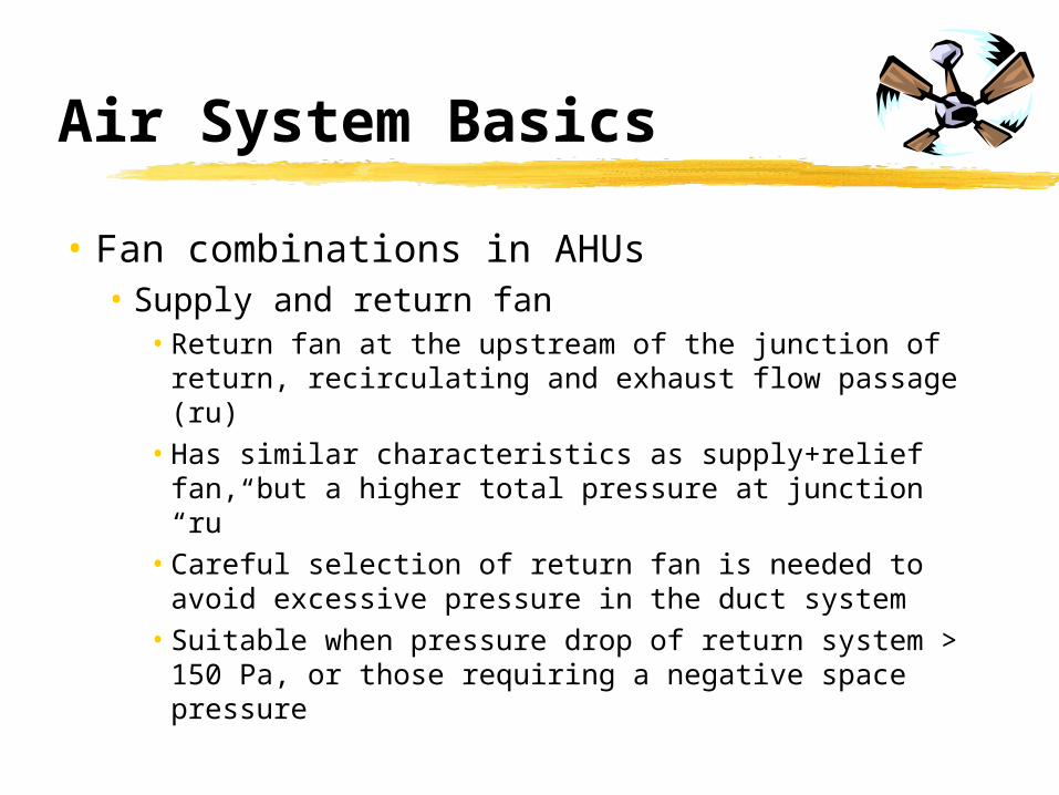
• Fan combinations in AHUs• Supply and return fan
• Return fan at the upstream of the junction of return, recirculating and exhaust flow passage (ru)
• Has similar characteristics as supply+relief fan, but a higher total pressure at junction “ru”
• Careful selection of return fan is needed to avoid excessive pressure in the duct system
• Suitable when pressure drop of return system > 150 Pa, or those requiring a negative space pressure

Supply and return fans

Air System Basics
• Year-round operation of a VAV system• Region I: Refrigeration/evaporative cooling
• Enthalpy of outdoor > that of recirculating air
• Region II: Free cooling & refrigeration• Enthalpy of outdoor ≤ that of recirculating air
• Region III: Free cooling, evaporative cooling & refrigeration
• Enthalpy of outdoor ≤ that of recirculating air
• Region VI: Winter heating

Control diagram of a VAV reheat system for year-round operation

Year-round operationRegion I: Refrigeration/evaporative coolingRegion II: Free cooling & refrigerationRegion III: Free cooling, evaporative cooling & refrigerationRegion VI: Winter heating

Air System Basics
• Economizer• A device consisting of dampers and control that
uses free cooling capacity of either outdoor air or evaporatively cooled water from cooling tower instead of mechanical refrigeration
• Air economizer:• Enthalpy-based
• Temperature-based
• Water economizer

Air System Basics
• Fan energy use• For each l/s air
supplied:
• For system using separate outdoor ventilation:
mf
syp
sl
W
1000/
mf
sySO
pR
sl
W
1000
)1(/ ,

Air System Basics
• Outdoor ventilation air supply• Aims
• Provide acceptable indoor air quality
• Achieve energy efficiency in the system
• ASHRAE Standard 62-2001 (IAQ standard)• Demand-based outdoor ventilation air control
using CO2 as an indicator
• CO2 concentration < 800-1,000 ppm
• A specific indoor air contaminant can also be used

Air System Basics
• Outdoor ventilation air supply• Minimum outdoor air control
• Type I: uses a CO2 or mixed gas sensor + DDC controller to control the volume flow rate of outdoor air
• The best one but can be expensive
• Type II: uses a CO2 or mixed gas sensor + DDC controller to control the ratio of the openings between outdoor and recirculating dampers
• Suitable for VAV system

Air System Basics
• Outdoor ventilation air supply• Minimum outdoor air control (cont’d)
• Type III: uses a flow sensor or a pressure sensor + DDC controller to control the dampers to provide nearly constant volume outdoor air intake
• More complicated & may cause energy waste
• Type IV: adjust the opening of outdoor damper manually to provide constant volume outdoor air
• Mainly used for constant-volume systems