Embed Size (px)
Citation preview

*MEC96UPFLOW / HORIZONTAL TWO-STAGE
GAS FURNACE
IOG-201108/14
(Type FSP CATEGORY IV Director Non Direct Vent Air Furnace)
These furnaces comply with requirements em-bodied in the American National Standard / Na-tional Standard of Canada ANSI Z21.47·CSA-2.3Gas Fired Central Furnaces.
Installer:Affix all manuals
adjacent to the unit.
As a professional installer you have an obligation to knowthe product better than the customer. This includes all safetyprecautions and related items.
Prior to actual installation, thoroughly familiarize yourselfwith this Instruction Manual. Pay special attention to allsafety warnings. Often during installation or repair it ispossible to place yourself in a position which is morehazardous than when the unit is in operation.
Remember, it is your responsibility to install the productsafely and to know it well enough to be able to instruct acustomer in its safe use.
Safety is a matter of common sense...a matter of thinkingbefore acting. Most dealers have a list of specific goodsafety practices...follow them.
The precautions listed in this Installation Manual are intendedas supplemental to existing practices. However, if there isa direct conflict between existing practices and the contentof this manual, the precautions listed here take precedence.
RECOGNIZE THIS SYMBOL
AS A SAFETY PRECAUTION.
*NOTE: Please contact your distributor or our website forthe applicable Specification Sheet referred to in this manual.
TABLE OF CONTENTS
5151 San Felipe Suite 500Houston, TX 77056
www.goodmanmfg.com • www.amana-hac.com© 2014 Goodman Manufacturing Company, L.P.
is a registered trademark of Maytag Corporation or its related companies and is used under license. All rights reserved.
SAFETY CONSIDERATIONS.................................... 3SHIPPING INSPECTION ............................................ 4ELECTROSTATIC DISCHARGE (ESD) PRECAUTIONS .................... 4TO THE INSTALLER ............................................. 5
PRODUCT DESCRIPTION ....................................... 5FEATURES ...................................................... 5
PRODUCT APPLICATION ....................................... 5LOCATION REQUIREMENTS & CONSIDERATIONS ........... 6
CLEARANCES AND ACCESSIBILITY ................................... 7EXISTING FURNACE REMOVAL ..................................... 8THERMOSTAT LOCATION .......................................... 8COMBUSTION & VENTILATION AIR REQUIREMENTS ................... 9
INSTALLATION POSITIONS .................................... 9HORIZONTAL APPLICATIONS & CONSIDERATIONS ......... 9
FURNACE SUSPENSION .......................................... 10FRONT COVER PRESSURE SWITCH TUBE LOCATION ................ 10DRAIN TRAP AND LINES ........................................ 10HORIZONTAL FURNACE LEVELING ................................ 10ALTERNATE ELECTRICAL AND GAS LINE CONNECTIONS .............. 10DRAIN PAN ................................................... 10FREEZE PROTECTION ........................................... 10
PROPANE GAS/HIGH ALTITUDE INSTALLATIONS .......... 10VENT/FLUE PIPE & COMBUSTION AIR PIPE ................ 11
DUAL CERTIFICATION: NON-DIRECT/DIRECT VENT ................. 11MATERIALS AND JOINING METHODS .............................. 11PROPER VENT/FLUE AND COMBUSTION AIR PIPING PRACTICES ...... 12TERMINATION LOCATIONS ........................................ 12CANADIAN VENTING REQUIREMENTS .............................. 13STANDARD FURNACE CONNECTIONS .............................. 13VENT/FLUE PIPE .............................................. 13NON-DIRECT VENT (SINGLE PIPE) PIPING ........................ 14VENT/INTAKE TERMINATIONS FOR INSTALLATION
OF MULTIPLE DIRECT VENT FURNACES ......................... 18CONCENTRIC VENT TERMINATION................................. 18SIDE WALL VENT KIT .......................................... 18
CONDENSATE DRAIN LINES & DRAIN TRAP ................ 18UPFLOW MODEL INSTALLED VERTICALLY .......................... 19DRAIN EXITING RIGHT SIDE ..................................... 19GENERAL DRAIN INFORMATION ................................... 19FIELD SUPPLIED DRAIN ......................................... 19DRAIN EXITING LEFT SIDE ...................................... 20UPFLOW MODEL INSTALLED HORIZONTALLY WITH RIGHT SIDE DOWN 20UPFLOW MODEL INSTALLED HORIZONTALLY WITH LEFT SIDE DOWN . 20

2
ELECTRICAL CONNECTIONS ................................. 21WIRING HARNESS .............................................. 21115 VOLT LINE CONNECTIONS .................................. 21JUNCTION BOX RELOCATION ..................................... 2124 VOLT THERMOSTAT WIRING.................................. 22SINGLE-STAGE HEATING THERMOSTAT APPLICATION ................ 23FOSSIL FUEL APPLICATIONS ...................................... 23TWINNING .................................................... 23115 VOLT LINE CONNECTION OF ACCESSORIES
(HUMIDIFIER AND ELECTRONIC AIR CLEANER) .................. 23GAS SUPPLY AND PIPING ...................................... 24
HIGH ALTITUDE DERATE ........................................ 24PROPANE GAS CONVERSION ..................................... 24GAS PIPING CONNECTIONS ...................................... 25PROPANE GAS TANKS AND PIPING ............................... 26
CIRCULATING AIR & FILTERS ................................ 27DUCT WORK - AIR FLOW ....................................... 27CHECKING DUCT STATIC ........................................ 27BOTTOM RETURN AIR OPENING [UPFLOW MODELS] ............... 28FILTERS - READ THIS SECTION BEFORE INSTALLING
THE RETURN AIR DUCT WORK ............................... 28UPRIGHT INSTALLATIONS ......................................... 29HORIZONTAL INSTALLATIONS ..................................... 29
STARTUP PROCEDURE & ADJUSTMENT ..................... 29DRAIN TRAP PRIMING .......................................... 29FURNACE OPERATION ........................................... 29GAS SUPPLY PRESSURE MEASUREMENT ........................... 30GAS MANIFOLD PRESSURE MEASUREMENT AND ADJUSTMENT ........ 31GAS INPUT RATE MEASUREMENT (NATURAL GAS ONLY) ........... 32TEMPERATURE RISE ............................................ 32CIRCULATOR BLOWER SPEEDS ................................... 33BLOWER HEAT OFF DELAY TIMINGS ............................. 37
NORMAL SEQUENCE OF OPERATION ........................ 37POWER UP ................................................... 37HEATING MODE ............................................... 37COOLING MODE ............................................... 38FAN ONLY MODE ............................................. 38
OPERATIONAL CHECKS ....................................... 38SAFETY CIRCUIT DESCRIPTION .............................. 38
INTEGRATED CONTROL MODULE ................................. 38PRIMARY LIMIT ................................................. 38AUXILIARY LIMIT ...............................................38ROLLOUT LIMIT ...............................................39PRESSURE SWITCHES ........................................... 39FLAME SENSOR ................................................ 39TROUBLESHOOTING ............................................. 39ELECTROSTATIC DISCHARGE (ESD) PRECAUTIONS ................... 39CHECKING FLAME SENSOR ...................................... 39LIMIT FAULT CODES ........................................... 39DIAGNOSTIC CHART ............................................ 40FAULT RECALL ................................................ 40RESETTING FROM LOCKOUT ..................................... 41
MAINTENANCE ................................................. 41ANNUAL INSPECTION ........................................... 41FILTERS ....................................................... 41BURNERS ..................................................... 42INDUCED DRAFT AND CIRCULATOR BLOWERS ...................... 42CONDENSATE TRAP AND DRAIN SYSTEM (QUALIFIED SERVICER ONLY) 42FLAME SENSOR (QUALIFIED SERVICER ONLY) ..................... 42FLUE PASSAGES (QUALIFIED SERVICER ONLY) ..................... 43
BEFORE LEAVING AN INSTALLATION ........................ 43REPAIR AND REPLACEMENT PARTS.......................... 43TROUBLESHOOTING CHART ................................. 44WIRING DIAGRAM ............................................. 46SPECIAL INSTRUCTIONS FOR PRODUCTS
INSTALLED IN THE STATE OF MASSACHUSETTS... 47

3
TO PREVENT PERSONAL INJURY OR DEATH DUE TO IMPROPER INSTALLATION, ADJUSTMENT, ALTERATION, SERVICE OR MAINTENANCE, REFER TO THIS MANUAL. FOR ADDITIONAL ASSISTANCE OR INFORMATION, CONSULT A QUALIFIED INSTALLER, SERVICER AGENCY OR THE GAS SUPPLIER.
WARNING
IF THE INFORMATION IN THESE INSTRUCTIONS IS NOT FOLLOWED EXACTLY, A FIRE OR EXPLOSION MAY RESULT CAUSING PROPERTYDAMAGE, PERSONAL INJURY OR LOSS OF LIFE.
DO NOT STORE OR USE GASOLINE OR OTHER FLAMMABLE VAPORS AND LIQUIDS IN THE VICINITY OF THIS OR ANY OTHER APPLIANCE.
DO NOT TRY TO LIGHT ANY APPLIANCE.DO NOT TOUCH ANY ELECTRICAL SWITCH; DO NOT USE ANY PHONE IN YOUR BUILDING.IMMEDIATELY CALL YOUR GAS SUPPLIER FROM A NEIGHBOR’S PHONE. FOLLOW THE GAS SUPPLIER’S INSTRUCTIONS.IF YOU CANNOT REACH YOUR GAS SUPPLIER, CALL THE FIRE DEPARTMENT.
INSTALLATION AND SERVICE MUST BE PERFORMED BY A QUALIFIED INSTALLER, SERVICE AGENCY OR THE GAS SUPPLIER.
WHAT TO DO IF YOU SMELL GAS:
WARNING
THIS PRODUCT CONTAINS OR PRODUCES A CHEMICAL OR CHEMICALS WHICH MAY CAUSE SERIOUS ILLNESS OR DEATH AND WHICH ARE KNOWN TO THE STATE OF CALIFORNIA TO CAUSE CANCER, BIRTH DEFECTS OR OTHER REPRODUCTIVE HARM.
WARNING
HEATING UNIT SHOULD NOT BE UTILIZED WITHOUT REASONABLE, ROUTINE, INSPECTION, MAINTENANCE AND SUPERVISION. IF THE BUILDING IN WHICH ANY SUCH DEVICE IS LOCATED WILL BE VACANT, CARE SHOULD BE TAKEN THAT SUCH DEVICE IS ROUTINELY INSPECTED, MAINTAINED AND MONITORED. IN THE EVENT THAT THE BUILDING MAYBE EXPOSED TO FREEZING TEMPERATURES AND WILL BE VACANT, ALL WATER-BEARING PIPES SHOULD BE DRAINED, THE BUILDING SHOULD BE PROPERLY WINTERIZED, AND THE WATER SOURCE CLOSED. IN THE EVENT THAT THE BUILDING MAY BE EXPOSED TO FREEZING TEMPERATURES AND WILL BE VACANT, ANY HYDRONIC COIL UNITS SHOULD BE DRAINED AS WELL AND, IN SUCH CASE, ALTERNATIVE HEAT SOURCES SHOULD BE UTILIZED.
WARNING
TO PREVENT POSSIBLE PROPERTY DAMAGE, PERSONAL INJURY OR DEATH DUE TO ELECTRICAL SHOCK, THE FURNACE MUST BE LOCATED TO PROTECT THE ELECTRICAL COMPONENTS FROM WATER.
WARNING
Drain trap must be primed at time of installation. Trap isinternally partitioned; add water to both inlet ports until wa-ter appears at both sides of the outlet opening. Failure toprime trap at time of installation may have a negative ef-fect on combustion quality and pressure switch action.
GOODMAN WILL NOT BE RESPONSIBLE FOR ANY INJURY OR PROPERTY DAMAGE ARISING FROM IMPROPER SERVICE OR SERVICE PROCEDURES. IF YOU INSTALL OR PERFORM SERVICE ON THIS UNIT, YOU ASSUME RESPONSIBILITY FOR ANY PERSONAL INJURY OR PROPERTY DAMAGE WHICH MAY RESULT. MANY JURISDICTIONS REQUIRE A LICENSE TO INSTALL OR SERVICE HEATING AND AIR CONDITIONING EQUIPMENT.
WARNING
SAFETY CONSIDERATIONS
Adhere to the following warnings and cautions when install-ing, adjusting, altering, servicing, or operating the furnace.To ensure proper installation and operation, thoroughly readthis manual for specifics pertaining to the installation andapplication of this product.
This furnace is manufactured for use with natural gas. Itmay be field converted to operate on L.P. gas by using theappropriate L.P. conversion kit listed in the PROPANE GAS/HIGH ALTITUDE INSTALLATIONS section of this manual
Install this furnace only in a location and position as speci-fied in LOCATION REQUIREMENTS & CONSIDERATIONS sec-tion and INSTALLATION POSITIONS section of this manual.
Provide adequate combustion and ventilation air to the fur-nace as specified in COMBUSTION & VENTILATION AIR RE-QUIREMENTS section of this manual.
Combustion products must be discharged to the outdoors.Connect this furnace to an approved vent system only, asspecified in VENT/FLUE PIPE & COMBUSTION AIR PIPE sec-tion of this manual.
Never test for gas leaks with an open flame. Use a commer-cially available soap solution made specifically for the detec-tion of leaks to check all connections, as specified in GASSUPPLY AND PIPING section of this manual.
Always install a furnace to operate within the furnace’s in-tended temperature-rise range with a duct system which hasexternal static pressure within the allowable range, as speci-fied on the furnace rating plate and OPERATIONAL CHECKSsection of these instructions.
When a furnace is installed so that supply ducts carry aircirculated by the furnace to areas outside the space contain-ing the furnace, the return air shall also be handled by duct(s)sealed to the furnace casing and terminating outside thespace containing the furnace.
A gas-fired furnace for installation in a residential garagemust be installed as specified in the LOCATION REQUIRE-MENTS AND CONSIDERATIONS section of this manual.
This furnace may be used as a construction site heater onlyif certain conditions are met. These conditions are listed inthe PRODUCT APPLICATION section of this manual.

4
DANGER
0140M00020-D
CARBON MONOXIDE POISONING HAZARDSpecial warning for installation of furnaces or air handling units in enclosed area such as garages, utility rooms or parking areas. Carbon monoxide producingdevices (such as automobile, space heater, gas water heater, etc.) Should not be operated in enclosed areas such as unventilated garages or utility rooms becauseof the danger of carbon monoxide (CO) poisoning resulting from the exhaust emissions. If a furnace or air handler is installed in an enclosed area and a carbonmonoxide producing device is operated therein, there must be adequate direct outside ventilation. Carbon monoxide emissions can be (re)circulated throughoutthe structure if the furnace or air handler is operating in any mode. CO can cause serious illness including permanent brain damage or death.
Avertissement special au sujet de l'installation d'appareils de chauffage ou de traitement d'air dans des endroits clos, tets les garages, les locaux d'entretien et lesRISQUE D'EMPOISONNEMENT AU MONOXYDE DE CARBONE
stationnements. Evitez de mettre en marche les appareils produisant du monoxyde de carbone (tels que les automobile, les appareils de chauffage autonome,etc.)dans des endroits non ventilés tels que les d'empoisonnement au monoxyde de carbone. Si vous devez faire fonctionner ces appareils dans un endroit clos, assures-vous qu'il y ait une ventilation directe provenant de l'exterie . Les émissions de monoxyde de carbone peuvent etre recircules dans les endroits clos, si l'appareil de chauffage ou de traitement d'air sont en marche. Le monoxyde de carbone peut causer des maladies graves telles que des dommages permanents au cerveau et meme la mort.
Advertencia especial para la instalación de calentadores ó maneja oras de aire en áreas cerradas como estacionamientos ó cuartos de servicio. Los equipos óRIESGO DE INTOXICACIÓN POR MONÓXIDO DE CARBONOaparatos que producen monóxido de carbono (tal como automóvil, calentador de gas, calentador de agua por medio de gas, etc) no deben ser operados enáreas cerradas debido al riesgo de envenenamiento por monóxido de carbono (CO) que resulta de las emisiones de gases de combustión. Si el equipo óaparato se opera en dichas áreas, debe existir una adecuada ventilac ón directa al exterior. Las emisiones de monóxido de carbono pueden circular a travésdel aparato cuando se opera en cualquier modo. El monóxido de carbono puede causar enfermedades severas como daño cerebral permanente ó muerte.
'
DANGER
PELIGRO
SHIPPING INSPECTION
All units are securely packed in shipping containers tested accord-ing to International Safe Transit Association specifications. Thecarton must be checked upon arrival for external damage. If dam-age is found, a request for inspection by carrier’s agent must bemade in writing immediately.
The furnace must be carefully inspected on arrival for damage andbolts or screws which may have come loose in transit. In the eventof damage the consignee should:1. Make a notation on delivery receipt of any visible damage to
shipment or container.2. Notify carrier promptly and request an inspection.3. With concealed damage, carrier must be notified as soon as possible - preferably within five days.4. File the claim with the following support documents within a nine month statute of limitations.• Original or certified copy of the Bill of Lading, or indemnity bond.• Original paid freight bill or indemnity in lieu thereof.• Original or certified copy of the invoice, showing trade and other discounts or reductions.• Copy of the inspection report issued by carrier’s representative at the time damage is reported to carrier.
The carrier is responsible for making prompt inspection of damage and for a thorough investigation of each claim. The distributor ormanufacturer will not accept claims from dealers for transportation damage.
ELECTROSTATIC DISCHARGE (ESD) PRECAUTIONS
NOTE: Discharge your body’s static electricity before touching unit. An electrostatic discharge can adversely affect electricalcomponents.
Use the following precautions during furnace installation and servicing to protect the integrated control module from damage. Byputting the furnace, the control, and the person at the same electrostatic potential, these steps will help avoid exposing theintegrated control module to electrostatic discharge. This procedure is applicable to both installed and non-installed (ungrounded)furnaces.1. Disconnect all power to the furnace. Do not touch the integrated control module or any wire connected to the control prior to
discharging your body’s electrostatic charge to ground.
SHOULD OVERHEATING OCCUR OR THE GAS SUPPLY FAIL TO SHUT OFF, TURN OFF THE MANUAL GAS SHUTOFF VALVE EXTERNAL TO THE FURNACE BEFORE TURNING OFF THE ELECTRICAL SUPPLY.
WARNING
POSSIBLE PROPERTY DAMAGE, PERSONAL INJURY OR DEATH DUE TO FIRE, EXPLOSION, SMOKE, SOOT, CONDENSATION, ELECTRICAL SHOCK OR CARBON MONOXIDE MAY RESULT FROM IMPROPER INSTALLATION, REPAIR OPERATION, OR MAINTENANCE OF THIS PRODUCT.
WARNING

5
2. Firmly touch a clean, unpainted, metal surface of the furnaces near the control. Any tools held in a person’s hand duringgrounding will be discharged.
3. Service integrated control module or connecting wiring following the discharge process in step 2. Use caution not to rechargeyour body with static electricity; (i.e., do not move or shuffle your feet, do not touch ungrounded objects, etc.). If you comein contact with an ungrounded object, repeat step 2 before touching control or wires.
4. Discharge your body to ground before removing a new control from its container. Follow steps 1 through 3 if installing thecontrol on a furnace. Return any old or new controls to their containers before touching any ungrounded object.
TO THE INSTALLER
Before installing this unit, please read this manual thoroughly tofamiliarize yourself with specific items which must be adhered to,including but not limited to: unit maximum external static pres-sure, gas pressures, BTU input rating, proper electrical connec-tions, circulating air temperature rise, minimum or maximum CFM,and motor speed connections.
PRODUCT DESCRIPTION
FEATURES
The *MEC96 furnace may be installed upflow or horizontally with left or right side down. The *MEC96 two-stage gas furnacefeatures a multi-speed ECM indoor fan motor, two heating inputs (W1 & W2), two cooling inputs (YLO & Y) and a two stagegas valve. A single stage heating thermostat may also be used in conjunction with timed transition to high fire by the furnaceintegrated control board.
PRODUCT APPLICATION
This furnace is primarily designed for residential home-heating applications. It is NOT designed or certified for use in mobile homes,trailers or recreational vehicles. Neither is it designed or certified for outdoor applications. The furnace must be installed indoors(i.e., attic space, crawl space, or garage area provided the garage area is enclosed with an operating door).
This furnace can be used in the following non-industrial commercial applications:
Schools, Office buildings, Churches, Retail stores, Nursing homes, Hotels/motels, Common or office areas
In such applications, the furnace must be installed with the following stipulations:• It must be installed per the installation instructions provided and per local and national codes.• It must be installed indoors in a building constructed on site.• It must be part of a ducted system and not used in a free air delivery application.• It must not be used as a “make-up” air unit.• It must be installed as a two-pipe system for combustion air.• All other warranty exclusions and restrictions apply This furnace is an ETL dual-certified appliance and is appropriate for use
with natural or propane gas (NOTE: If using propane, a propane conversion kit is required).
Dual certification means that the combustion air inlet pipe is optional and the furnace can be vented as a:Non-direct vent (single pipe) central forced air furnace in which combustion air is taken from the installation area or from airducted from the outside or,Direct vent (dual pipe) central forced air furnace in which all combustion air supplied directly to the furnace burners througha special air intake system outlined in these instructions.
This furnace may be used as a construction site heater ONLY if all of the following conditions are met:• The vent system is permanently installed per these installation instructions.• A room thermostat is used to control the furnace. Fixed jumpers that provide continuous heating CANNOT be used and can
cause long term equipment damage.• Return air ducts are provided and sealed to the furnace.• A return air temperature range between 60ºF (16ºC) and 80ºF (27ºC) is maintained.• Air filters are installed in the system and maintained during construction replaced as appropriate during construction, and
upon completion of construction.• The input rate and temperature rise are set per the furnace rating plate.
TO PREVENT PROPERTY DAMAGE, PERSONAL INJURY OR DEATH DUE TO FIRE, DO NOT INSTALL THIS FURNACE IN A MOBILE HOME, TRAILER, OR RECREATIONAL VEHICLE.
WARNING

6
• 100% outside air is provided for combustion air requirements during construction. Temporary ducting can be used.NOTE: Do not connect the temporary duct directly to the furnace. The duct must be sized for adequate combustion andventilation in accordance with the latest edition of the National Fuel Gas Code NFPA 54/ANSI Z223.1 or CAN/CSA B149.1Installation Codes.
• The furnace heat exchanger, components, duct system, air filters and evaporator coils are thoroughly cleaned following finalconstruction clean up.
• All furnace operating conditions (including ignition, input rate, temperature rise and venting) are verified according tothese installation instructions.
NOTE: The Commonwealth of Massachusetts requires that the following additional requirements must also be met:• Gas furnaces must be installed by a licensed plumber or gas fitter.• A T-handle gas cock must be used.• If the unit is to be installed in an attic, the passageway to and the service area around the unit must have flooring.
To ensure proper furnace operation, install, operate and maintain the furnace in accordance with these installation andoperation instructions, all local building codes and ordinances. In their absence, follow the latest edition of the National Fuel GasCode (NFPA 54/ANSI Z223.1), and/or CAN/CSA B149 Installation Codes, local plumbing or waste water codes, and other applicablecodes.
A copy of the National Fuel Gas Code (NFPA 54/ANSI Z223.1) can be obtained from any of the following:American National Standards Institute National Fire Protection Association CSA International 25 West 43rd Street, 4th Floor 1 Batterymarch Park 8501 East Pleasant Valley
New York, NY 10036 Quincy, MA 012169-7471 Independence, OH 44131
The rated heating capacity of the furnace should be greater than or equal to the total heat loss of the area to be heated. The totalheat loss should be calculated by an approved method or in accordance with “ASHRAE Guide” or “Manual J-Load Calculations”published by the Air Conditioning Contractors of America.
A copy of the CAN/CSA B149 Installation Codes can also be obtained from:CSA International
178 Rexdale BoulevardEtobicoke, Ontario, Canada M9W 1R3
LOCATION REQUIREMENTS & CONSIDERATIONS
Follow the instructions listed below and the guidelines provided in the Combustion and Ventilation Air Requirements section whenselecting a furnace location.
TO PREVENT POSSIBLE EQUIPMENT DAMAGE, PROPERTY DAMAGE, PERSONAL INJURY OR DEATH, THE FOLLOWING BULLET POINTS MUST BE OBSERVED WHEN INSTALLING THIS UNIT.
WARNING
POSSIBLE PROPERTY DAMAGE, PERSONAL INJURY OR DEATH DUE TO FIRE, EXPLOSION, SMOKE, SOOT, CONDENSATION, ELECTRICAL SHOCK OR CARBON MONOXIDE MAY RESULT FROM IMPROPER INSTALLATION, REPAIR OPERATION, OR MAINTENANCE OF THIS PRODUCT.
WARNING
• Centrally locate the furnace with respect to the proposed or existing air distribution system.• Ensure the temperature of the return air entering the furnace is between 55°F and 100°F when the furnace is heating.• Provide provisions for venting combustion products outdoors through a proper venting system. Special consideration
should be given to vent/flue pipe routing and combustion air intake pipe when applicable. Refer to Vent/Flue Pipe andCombustion Air Pipe -Termination Locations for appropriate termination locations and to determine if the piping systemfrom furnace to termination can be accomplished within the guidelines given. NOTE: The length of flue and/or combustionair piping can be a limiting factor in the location of the furnace.
• Locate the furnace so condensate flows downwards to the drain. Do not locate the furnace or its condensate drainagesystem in any area subject to below freezing temperatures without proper freeze protection. Refer to Condensate DrainLines and Trap for further details.
• Ensure adequate combustion air is available for the furnace. Improper or insufficient combustion air can expose buildingoccupants to gas combustion products that could include carbon monoxide. Refer to Combustion and Ventilation AirRequirements.
• Set the furnace on a level floor to enable proper condensate drainage. If the floor becomes wet or damp at times, place thefurnace above the floor on a concrete base sized approximately 1-1/2" larger than the base of the furnace. Refer to theHorizontal Applications and Considerations for leveling of horizontal furnaces.

7
• Ensure upflow or horizontal furnaces are not installed directly on carpeting, or any other combustible material. The onlycombustible material allowed is wood.
• Exposure to contaminated combustion air will result in safety and performance-related problems. Do not install the furnacewhere the combustion air is exposed to the following substances:permanent wave solutions chlorinated waxes or cleaners chlorine-basedcarbon tetrachloride water softening chemicals swimming pool chemicalsdeicing salts or chemicals halogen type refrigerantscleaning solutions (such as perchloroethylene) printing inkspaint removers varnishes hydrochloric acidcements and glues antistatic fabric softeners for clothes dryers
• Seal off a non-direct vent furnace if it is installed near an area frequently contaminated by any of the above substances. Thisprotects the non-direct vent furnace from airborne contaminants. To ensure that the enclosed non-direct vent furnace hasan adequate supply of combustion air, vent from a nearby uncontaminated room or from outdoors. Refer to the Combustionand Ventilation Air Requirements for details.
• If the furnace is used in connection with a cooling coil unit, install the furnace upstream or in parallel with the cooling coilunit. Premature heat exchanger failure will result if the cooling unit is placed ahead of the furnace.For vertical applications, the minimum cooling coil width shall not be less than furnace width minus 1”.For upflow applications, the front of the coil and furnace must face the same direction.
• If the furnace is installed in a residential garage, position the furnace so that the burners and ignition source are located notless than 18 inches (457 mm) above the floor. Protect the furnace from physical damage by vehicles.
• If the furnace is installed horizontally, ensure the access doors are not on the “up/top” or “down/bottom” side of thefurnace.
• Do not connect this furnace to a chimney flue that serves a separate appliance designed to burn solid fuel.
CLEARANCES AND ACCESSIBILITY
NOTES:• For servicing or cleaning, a 24” front clearance is required.• Unit connections (electrical, flue and drain) may necessitate greater clearances than the minimum clearances listed
above.• In all cases, accessibility clearance must take
precedence over clearances from the enclosure whereaccessibility clearances are greater.
Installations must adhere to the clearances to combustible mate-rials to which this furnace has been design certified. The mini-mum clearance information for this furnace is provided on theunit’s clearance label. These clearances must be permanently main-tained. Clearances must also accommodate an installation’s gas,electrical, and drain trap and drain line connections. If the alter-nate combustion air intake or vent/flue connections are used additional clearance must be provided to accommodate these connec-tions. Refer to Vent/Flue Pipe and Combustion Air Pipe for details.
NOTE: In addition to the required clearances to combustible materials, a minimum of 24 inches service clearance must be availablein front of the unit.
TOP
BOTTOM
TOP
BOTTOM
Figure 1
A furnace installed in a confined space (i.e., a closet or utility room) must have two ventilation openings with a total minimum freearea of 0.25 square inches per 1,000 BTU/hr of furnace input rating. Refer to Specification Sheet applicable to your model forminimum clearances to combustible surfaces. One of the ventilation openings must be within 12 inches of the top; the other openingmust be within 12 inches of the bottom of the confined space. In a typical construction, the clearance between the door and doorframe is usually adequate to satisfy this ventilation requirement.
POSITION* SIDES REAR FRONT BOTTOM FLUE TOP
Upflow 0" 0" 3" C 0" 1"
Horizontal 6" 0" 3" C 0" 6"
C = If placed on combustible floor, floor MUST be wood only.
*MEC96 MINIMUM CLEARANCES TO COMBUSTIBLE MATERIALS
(INCHES)

8
EXISTING FURNACE REMOVAL
NOTE: When an existing furnace is removed from a venting system serving other appliances, the venting system may be too large toproperly vent the remaining attached appliances.
The following vent testing procedure is reproduced from the American National Standard/National Standard of Canada for Gas-Fired Central Furnaces ANSI Z21.47, CSA-2.3 latest edition Section 1.23.1.
The following steps shall be followed with each appliance connected to the venting system placed in operation, while any otherappliances connected to the venting system are not in operation:
1. Seal any unused openings in the venting system.
2. Inspect the venting system for proper size and horizontal pitch, as required by the National Fuel Gas Code, ANSI Z223.1or the Natural Gas and Propane Installation Code, CSA B149.1-05 and these instructions. Determine that there is noblockage or restriction, leakage, corrosion and other deficiencies which could cause an unsafe condition.
3. As far as practical, close all building doors and windows and all doors between the space in which the appliance(s)connected to the venting system are located and other spaces of the building.
4. Close fireplace dampers.
5. Turn on clothes dryers and any appliance not connected to the venting system. Turn on any exhaust fans, such as rangehoods and bathroom exhausts, so they shall operate at maximum speed. Do not operate a summer exhaust fan.
6. Follow the lighting instructions. Place the appliance being inspected in operation. Adjust thermostat so appliance shalloperate continuously.
7. Test for spillage from draft hood appliances at the draft hood relief opening after 5 minutes of main burner operation.Use the flame of a match or candle.
8. If improper venting is observed during any of the above tests, the venting system must be corrected in accordancewith the National Fuel Gas Code ANSI Z223.1/NFPA 54 and/or National Gas and Propane Installation Code CSA B149.1-05.
9. After it has been determined that each appliance connected to the venting system properly vents when tested asoutlined above, return doors, windows, exhaust fans, fireplace dampers and any other gas burning appliance to theirprevious conditions of use.
If resizing is required on any portion of the venting system, use the appropriate table in Appendix G in the latest edition of theNational Fuel Gas Code ANSI Z223.1 and/or CSA B149.1-05 Installation Codes.
THERMOSTAT LOCATION
The thermostat should be placed approximately five feet from the floor on a vibration-free, inside wall in an area having good aircirculation. Do not install the thermostat where it may be influenced by any of the following:
• Drafts, or dead spots behind doors, in corners, or under cabinets.• Hot or cold air from registers.• Radiant heat from the sun.• Light fixtures or other appliances.• Radiant heat from a fireplace.• Concealed hot or cold water pipes, or chimneys.• Unconditioned areas behind the thermostat, such as an outside wall.
Consult the instructions packaged with the thermostat for mounting instructions and further precautions.
9
COMBUSTION & VENTILATION AIR REQUIREMENTS
Improved construction and additional insulation in buildings havereduced heat loss by reducing air infiltration and escape arounddoors and windows. These changes have helped in reducing heat-ing/cooling costs but have created a problem supplying combus-tion and ventilation air for gas fired and other fuel burning appli-ances. Appliances that pull air out of the house (clothes dryers,exhaust fans, fireplaces, etc.) increase the problem by starving appliances for air.
House depressurization can cause back drafting or improper combustion of gas-fired appliances, thereby exposing building occu-pants to gas combustion products that could include carbon monoxide.
If this furnace is to be installed in the same space with other gas appliances, such as a water heater, ensure there is an adequatesupply of combustion and ventilation air for the other appliances. Refer to the latest edition of the National Fuel Gas Code NFPA54/ANSI Z223.1 or CAN/CSA B149.1-05 Installation Codes or applicable provisions of the local building codes for determining thecombustion air requirements for the appliances.
Most homes will require outside air be supplied to the furnace area by means of ventilation grilles or ducts connecting directly tothe outdoors or spaces open to the outdoors such as attics or crawl spaces.
INSTALLATION POSITIONS
Figure 2A Figure 2B Figure 2C
Recommended Installation Positions
*MEC96 models may be installed upflow or horizontally with left or right side down. Do not install this furnace on its back. Forupright upflow furnaces, return air ductwork may be attached to the side panel(s) and/or basepan. For horizontal upflowfurnaces, return air ductwork must be attached to the basepan. NOTE: Ductwork must never be attached to the back of thefurnace. Contact your distributor for proper airflow requirements and number of required ductwork connections. Refer to“Recommended Installation Positions” figure for appropriate installation positions, ductwork connections, and resulting airflowarrangements.
HORIZONTAL APPLICATIONS & CONSIDERATIONS
When installing a furnace horizontally, additional consideration must be given to the following:
TO AVOID PROPERTY DAMAGE, PERSONAL INJURY OR DEATH, SUFFICIENT FRESH AIR FOR PROPER COMBUSTION AND VENTILATION OF FLUE GASES MUST BE SUPPLIED. MOST HOMES REQUIRE OUTSIDE AIR BE SUPPLIED INTO THE FURNACE AREA.
WARNING

10
FURNACE SUSPENSION
If suspending the furnace from rafters or joists, use 3/8" threadedrod and 2”x2”x1/8” angle iron as shown in the following diagram.The length of rod will depend on the application and the clearancesnecessary.
If the furnace is installed in a crawl space it must be suspendedfrom the floor joist or supported by a concrete pad. Never installthe furnace on the ground or allow it to be exposed to water.
FRONT COVER PRESSURE SWITCH TUBE LOCATION
When an upflow model is installed horizontally with left sidedown, the front cover pressure switch tube must be relocatedto the lower port of the collector box cover.1. Remove tube from front cover pressure switch and collector
box cover.2. Remove rubber plug from bottom collector box port and install on top collector box port.3. Locate 24” x 1/4” tube in parts bag.4. Install one end on front cover pressure switch.5. Route tube to lower port on collector box cover and cut off excess tubing.
DRAIN TRAP AND LINES
In horizontal applications the condensate drain trap is secured to the furnace side panel, suspending it below the furnace. A minimumclearance of 5.5” below the furnace must be provided for the drain trap. Additionally, the appropriate downward piping slope must bemaintained from the drain trap to the drain location. Refer to Condensate Drain Trap and Lines for further details. If the drain trap anddrain line will be exposed to temperatures near or below freezing, adequate measures must be taken to prevent condensate fromfreezing.
HORIZONTAL FURNACE LEVELING
Leveling ensures proper condensate drainage from the heat exchanger and induced draft blower. For proper flue pipe drainage, thefurnace must be level lengthwise from end to end. The furnace should have a slight tilt from back to front with the access doorsdownhill from the back panel approximately 1/2 to 3/4 inches. The slight tilt allows the heat exchanger condensate, generated inthe recuperator coil, to flow forward to the recuperator coil front cover.
ALTERNATE ELECTRICAL AND GAS LINE CONNECTIONS
This furnace has provisions allowing for electrical and gas line connections through either side panel. In horizontal applications theconnections can be made either through the “top” or “bottom” of the furnace.
DRAIN PAN
A drain pan must be provided if the furnace is installed above a conditioned area. The drain pan must cover the entire area under thefurnace (and air conditioning coil if applicable).
FREEZE PROTECTION
Refer to Horizontal Applications and Conditions - Drain Trap andLines.
PROPANE GAS/HIGH ALTITUDE INSTALLATIONS
This furnace is shipped from the factory configured for natural gasat standard altitude. Propane gas installations require an orificeand orifice change to compensate for the energy content differ-ence between natural and propane gas.
High altitude installations may require both a pressure switch andan orifice/spring change. These changes are necessary to compensate for the natural reduction in the density of both the gas fuel andthe combustion air at higher altitude.
2" 2" 3/8" ANGLE IRON(3 PLACES)
X X
Figure 2
WARNING
POSSIBLE PROPERTY DAMAGE, PERSONAL INJURY OR DEATH MAY OCCUR IF THE CORRECT CONVERSION KITS ARE NOT INSTALLED. THE APPROPRIATE KITS MUST BE APPLIED TO ENSURE SAFE AND PROPER FURNACE OPERATION. ALL CONVERSIONS MUST BE PERFORMED BY A QUALIFIED INSTALLER OR SERVICE AGENCY.

11
For installations above 7000 feet, please refer to the furnaceSpecification Sheets for required kit(s).
Contact the distributor for a tabular listing of appropriatemanufacturer’s kits for propane gas and/or high altitude installa-tions. The indicated kits must be used to insure safe and properfurnace operation. All conversions must be performed by a quali-fied installer, or service agency.
VENT/FLUE PIPE & COMBUSTION AIR PIPE
A condensing gas furnace achieves its high level of efficiency byextracting almost all of the heat from the products of combustionand cooling them to the point where condensation takes place.Because of the relatively low flue gas temperature and water con-densation requirements, PVC pipe is used as venting material.
In addition to PVC and ABS pipe and fittings, Innoflue® byCentrotherm Eco Systems and PolyPro® by M&G Duravent arealso approved vent and combustion air materials for installa-tions in the U.S.A. and Canada. Manufacturers Installationinstructions for these products must be followed. These prod-ucts have specific instructions for installing, joining and ter-minating. Do not mix materials or components of one manu-facturer with materials or components of another manufacturer.
All furnaces are built with 2" vent / intake pipe and connectors. For furnaces requiring installation of 3" pipe, the transitionfrom 2" to 3" should be done as close to the furnace as practically possible.
This furnace must not be connected to Type B, BW, or L vent or vent connector, and must not be vented into any portion of a factorybuilt or masonry chimney except when used as a pathway for PVC as described later in this section. Never common vent this appliancewith another appliance or use a vent which is used by a solid fuel appliance. Do not use commercially available “no hub connectors”other than those shipped with this product.
It is the responsibility of the installer to follow the manufacturers’ recommendations and to verify that all vent/flue piping andconnectors are compatible with furnace flue products. Additionally, it is the responsibility of the installer to ensure that all piping andconnections possess adequate structural integrity and support to prevent flue pipe separation, shifting, or sagging during furnaceoperation.
DUAL CERTIFICATION: NON-DIRECT/DIRECT VENT
This furnace is dual certified and may be installed as a non-direct vent (single pipe) or direct vent (dual pipe) appliance. A non-directvent installation requires only a vent/flue pipe, while a direct vent installation requires both a vent/flue pipe and a combustion airintake pipe. Refer to the appropriate section for details concerning piping size, length, number of elbows, furnace connections, andterminations.
MATERIALS AND JOINING METHODS
Two-three-inch nominal diameter PVC Schedule 40 pipe meet-ing ASTM D1785, PVC primer meeting ASTM F656, and PVCsolvent cement meeting ASTM D2564 specifications must beused. Fittings must be DWV type fittings meeting ASTM D2665and ASTM D3311. Carefully follow the manufacturer’s instruc-tions for cutting, cleaning, and solvent cementing of PVC.
The use of Schedule 40 PVC or ABS cellular core (Foam Core)plastic pipe is also acceptable as a flue/vent and intake pipe material. PVC primer meeting ASTM F656 and PVC solventcement meeting ASTM D2564 specifications must be used. Fittings must be DWV type fittings meeting ASTM D2665 andASTM D3311. Carefully follow the manufactures instructions for cutting, cleaning and solvent cementing of PVC.
For Canadian installations; all PVC pipe, fittings and joining materials must be UL S636 listed.
HighStage
LowStage
Natural None #45 3.5" w.c. 1.9" w.c. None
Propane LPM -08* 1 1.25mm 10.0" w.c. 6.0" w.c. None
0-7000
1 LPM -08* supports both Honeywell and White-Rodgers 2-stage valvesN OT E: In Canada, gas furnaces are only certified to 4500 feet.
Gas Altitude Kit OrificeM anifo ld Pressure Pressure
SwitchChange
UPON COMPLETION OF THE FURNACE INSTALLATION, CAREFULLY INSPECT THE ENTIRE FLUE SYSTEM BOTH INSIDE AND OUTSIDE OF THE FURNACE TO ASSURE IT IS PROPERLY SEALED. LEAKS IN THE FLUE SYSTEM CAN RESULT IN SERIOUS PERSONAL INJURY OR DEATH DUE TO EXPOSURE TO FLUE PRODUCTS, INCLUDING CARBON MONOXIDE.
WARNING
FAILURE TO FOLLOW THESE INSTRUCTIONS CAN RESULT IN BODILY INJURY OR DEATH. CAREFULLY READ AND FOLLOW ALL INSTRUCTIONS GIVEN IN THIS SECTION.
WARNING
TO AVOID BODILY INJURY, FIRE OR EXPLOSION, SOLVENT CEMENTS MUST BE KEPT AWAY FROM ALL IGNITION SOURCES (I.E., SPARKS, OPEN FLAMES, AND EXCESSIVE HEAT) AS THEY ARE COMBUSTIBLE LIQUIDS. AVOID BREATHING CEMENT VAPORS OR CONTACT WITH SKIN AND/OR EYES.
WARNING

12
As an alternative to PVC pipe, primer, solvent cement, and fittings, ABS materials which are in compliance with the followingspecifications may be used. Two-or-three-inch ABS Schedule 40 pipe must meet ASTM D1527 and, if used in Canada, must be CSAlisted. Solvent cement for ABS to ABS joints must meet ASTM D2235 and, if used in Canada, must be CSA listed. The solvent cementfor the PVC to ABS transition joint must meet ASTM D3138. Fittings must be DWV type fittings meeting ASTM D2661 and ASTM D3311and, if used in Canada, must be CSA listed. Carefully follow the manufacturers’ instructions for cutting, cleaning, and solventcementing PVC and/or ABS.
All 90° elbows must be medium radius (1/4 bend DWV) or long radius (Long sweep 1/4 bend DWV) types conforming to ASTM D3311.A medium radius (1/4 bend DWV) elbow measures 3 1/16” minimum from the plane of one opening to the center line of the otheropening for 2” diameter pipe, and 4 9/16” minimum for 3” pipe.
PROPER VENT/FLUE AND COMBUSTION AIR PIPING PRACTICES
Adhere to these instructions to ensure safe and proper furnace performance. The length, diameter, and number of elbows of the vent/flue pipe and combustion air pipe (when applicable) affects the performance of the furnace and must be carefully sized. All pipingmust be installed in accordance with local codes and these instructions.
Some models require the use of 3” pipe. Do not transition from a 2” to 3” pipe in a horizontal section of pipe as this maycreate a water trap.
PREFERRED
TRANSITION NO LESS THAN 45 DEGREES TO HORIZONTAL PLANE TO AVOID CREATING A WATER TRAP IN VENT PIPING.
ACCEPTABLE
NO TRANSITION ON HORIZONTAL PLANE, THIS CREATES A WATER TRAP AND RESTRICTS FLUE GASES
Figure 4 Figure 5 Figure 6
Piping must be adequately secured and supported to prohibit sagging, joint separation, and/or detachment from the furnace.Horizontal runs of vent/flue piping must be supported every three to five feet and must maintain a 1/4 inch per foot downward slope,back towards the furnace, to properly return condensate to the furnace’s drain system. Allowances should be made for minorexpansion and contraction due to temperature variations. For this reason, particular care must be taken to secure piping when a longrun is followed by a short offset of less than 40 inches.
Precautions should be taken to prevent condensate from freezing inside the vent/flue pipe and/or at the vent/flue pipe termination.All vent/flue piping exposed to freezing temperatures below 35°F for extended periods of time must be insulated with 1/2” thickclosed cell foam. Also all vent/flue piping exposed outdoors in ex-cess of the terminations shown in this manual (or in unheated ar-eas) must be insulated with 1/2” thick closed cell foam. Inspectpiping for leaks prior to installing insulation.
TERMINATION LOCATIONS
NOTE: Refer to Location Requirements and Considerations forcombustion air contaminant restrictions.
The following bullets and diagram describe the restrictions con-cerning the appropriate location of vent/flue pipe and combustionair intake pipe (when applicable) terminations. Refer to Non-DirectVent (Single Pipe) Piping and Direct Vent (Dual Pipe) Piping locatedin this section for specific details on termination construction.
• All terminations (flue and/or intake) must be located at least12 inches above ground level or the anticipated snow level.
• Vent terminations (non-direct and direct vent) must terminateat least 3 feet above any forced air inlet located within 10feet.NOTE: This provision does not apply to the combustion airintake termination of a direct vent application.
12"
Non-Direct VentVent/Flue Termination
No Terminations Above Walkway
12"min.
4'min.
Non-Direct VentVent/Flue Termination
Direct VentVent/Flue Termination
<10'
Forced AirInlet
Non-Direct Vent&
Direct VentVent/Flue Terminations
Grade or Highest Anticipated Snow Level
3' min.
12" min.
4' min.
12" min.
Vent Termination ClearancesFigure 7

13
• The vent termination of a non-direct vent application must terminate at least 4 feet below, 4 feet horizontally from, or 1 footabove any door, window, or gravity air inlet into any building.
• The vent termination of a direct vent application must terminate at least 12 inches from any opening through which fluegases may enter a building (door, window, or gravity air inlet).
• The vent termination of vent pipe run vertically through a roof must terminate at least 12 inches above the roof line (or theanticipated snow level) and be at least 12 inches from any vertical wall (including any anticipated snow build up).
• A vent termination shall not terminate over public walkways or over an area where condensate or vapor could create anuisance or hazard or could be detrimental to the operation of regulators, relief valves, or other equipment.
• The combustion air intake termination of a direct vent application should not terminate in an area which is frequently dustyor dirty.
NOTE: In Canada, the Canadian Fuel Gas Code takes precedence over the preceding termination restrictions.
CANADIAN VENTING REQUIREMENTS
In Canada, venting must conform to the requirements of the current CAN/CSA-B149.1-05 Installation Code. Use only CSA-listed, ULC-S636 compliant two- or three-inch diameter PVC or ABS pipe, solvent cement, and fittings throughout. The certified piping should beclearly marked with the ULC Std “S636” on the pipe and fittings. Carefully follow the pipe manufacturers’ instructions for cutting,cleaning, and solvent cementing PVC and/or ABS.
The vent can be run through an existing unused chimney provided the space between the vent pipe and the chimney is insulated andclosed with a weather-tight, corrosion-resistant flashing.
STANDARD FURNACE CONNECTIONS
It is the responsibility of the installer to ensure that the piping connections to the furnace are secure, airtight, and adequatelysupported.
VENT/FLUE PIPE
The vent pipe outlet is sized to accept 2” pipe. Secure vent/flue pipe directly intothe furnace fitting with the appropriate glue. Alternately, a small section of 2" pipemay be glued in the furnace socket and a rubber coupling installed to allow removalfor future service. Combustion Air and Vent piping should be routed in a manner toavoid contact with refrigerant lines, metering devices, condensate drain lines, etc.If necessary, clearances may be increased by creating an offset using two 45 degreeelbows. This joint can be rotated on the fitting to establish maximum clearancebetween refrigerant lines, metering devices, and condensate drain lines, etc. Thisjoint is the equivalent of one 90 deg. elbow when considering elbow count.
NOTE: For non-direct vent installations, a minimum of one 90° elbow should be in-stalled on the combustion air intake coupling to guard against inadvertent blockage.
DIRECT VENT INSTALLATIONS
On upflow units secure the combustion air intake pipe directly to the air intake coupling or glue a short section of pipe intothe furnace vent fitting and install the rubber coupling supplied with the furnace.
NON-DIRECT VENT INSTALLATIONS
A minimum of one 90° elbow should be installed on the combustionair intake “coupling” to guard against inadvertent blockage.
ALTERNATE VENT/FLUE LOCATION
The alternate vent/flue location is the large hole directly in linewith the induced draft blower outlet. To use the alternate vent/fluelocation refer to the following steps and the “Alternate Vent/Flue Location” figure.
45 DEGREELONG-SWEEP
ELBOWS
VENT
Increased Clearance ConfigurationFigure 8
EDGES OF SHEET METAL HOLES MAY BE SHARP. USE GLOVES AS A PRECAUTION WHEN REMOVING HOLE PLUGS.
WARNING

14
NOTE: In the horizontal left installation position, a means ofcondensate collection must be provided to keep vent pipe con-densate from entering the draft inducer housing. If the ventdrain elbow is eliminated from the installation, an RF000142kit must be used.
1. Remove the four screws from the vent pipe flange on topthe furnace.
2. Remove the internal elbow and vent pipe3. Cut 2 1/2" from the flange .4. Remove plastic plug in line with the inducer outlet5. Install cut end of the flanged section and connect to inducer
with rubber coupling supplied with furnace.6. Install screws removed in step 1 securing flange to cabinet.
THE RUBBER ELBOW IS NOT DESIGNED TO SUPPORT A LOAD. WHEN THE RUBBER ELBOW IS MOUNTED EXTERNALLY TO THE FURNACE CABINET, EXTREME CARE MUST BE TAKEN TO ADEQUATELY SUPPORT FIELD-SUPPLIED VENT/FLUE PIPING, AS DAMAGE CAN RESULT IN LEAKS CAUSING BODILY INJURY OR DEATH DUE TO EXPOSURE TO FLUE GASES, INCLUDING CARBON MONOXIDE
WARNING
ALTERNATE COMBUSTION AIR PROVISION
(Upflow / Horizontal models only)When using the alternate venting location, either in a horizontal left side down installation or a vertical installation usingdown – venting, an alternate combustion air opening can be used. A locating dimple is located on the right side of thefurnace cabinet. The locating dimple is 1 7/8" measured from the front edge of the cabinet in line with the knock out. Touse the alternate combustion air location:1. Remove screws and combustion air flange from cabinet.2. Insert cabinet plug in unused combustion air hole.3. Drill a pilot hole at the cabinet dimple (size dictated by
knockout tool used).4. Use a knockout tool to create a 3" diameter hole5. Install combustion air flange and secure with screws
removed in step one.
NON-DIRECT VENT (SINGLE PIPE) PIPING
Non-direct vent installations require only a vent/flue pipe. The vent pipe can be run horizontally with an exit through the side of thebuilding or run vertically with an exit through the roof of the building. The vent can also be run through an existing unused chimney;however, it must extend a minimum of 12 inches above the top of the chimney. The space between the vent pipe and the chimneymust be closed with a weather-tight, corrosion-resistant flashing.
Although non-direct vent installations do not require a combustion air intake pipe, a minimum of one 90° elbow should be attached tothe furnace’s combustion air intake if: an upright installation uses the standard intake location, or a horizontal installation uses thealternate air intake location. This elbow will guard against inadvertent blockage of the air intake.
Insert flange. Cut 2 ½” long.
R 000142F
Figure 9
CU
T H
ER
E
Vent/Flue Pipe CutsFigure 10
BE SURE NOT TO DAMAGE INTERNAL WIRING OR OTHER COMPONENTS WHEN REINSTALLING COUPLING AND SCREWS.
CAUTION

15
VENT/FLUE PIPE LENGTHS AND DIAMETERS
Refer to the following table for applicable length, el-bows, and pipe diameter for construction of the vent/flue pipe system of a non-direct vent installation. Inaddition to the vent/flue pipe, a single 90° elbow shouldbe secured to the combustion air intake to preventinadvertent blockage. The tee used in the vent/fluetermination must be included when determining thenumber of elbows in the piping system.
VENT/FLUE PIPE TERMINATIONS
NOTE: If either a 90 degree or 45 degree elbow isused for termination, it must be pointed down-ward.
The vent/flue pipe may terminate vertically, as througha roof, or horizontally, as through an outside wall.
Vertical vent/flue pipe terminations should be as shownin the following figure. Refer to Vent/Flue Pipe andCombustion Air Pipe - Termination Locations for de-tails concerning location restrictions. The penetra-tion of the vent through the roof must be sealed tightwith proper flashing such as is used with a plasticplumbing vent.
Horizontal vent/flue pipe terminations should be asshown in the following figure. Refer to Vent/Flue Pipeand Combustion Air Pipe. To secure the pipe passingthrough the wall and prohibit damage to piping con-nections, a coupling should be installed on either sideof the wall and solvent cemented to a length of pipeconnecting the two couplings. The length of pipe should be the wall thickness plus the depth of the socket fittings to be installed onthe inside and outside of the wall. The wall penetration should be sealed with silicone caulking material.
1) Maximum allowable limits listed on individual lengths for inlet and flue and NOT a combination.2) Minimum requirement for each vent pipe is five (5) feet in length and one elbow/tee.3) Tee used in the vent/flue termination must be included when determining the number of
elbows in the piping system.4) 2 1/2” or 3” diameter pipe can be used in place of 2” diameter pipe.5) Increased Clearance Configurations using (2) 45 deg. Long Sweep elbows should be considered
equivalent to one 90 deg. elbow.6) One 90° elbow should be secured to the combustion air intake connection.
1 2 3 4 5 6 7 8
40,0002
or 2 1/2120 115 110 105 100 95 90 85
60,0002
or 2 1/295 90 85 80 75 70 65 60
80,000 "B" 2 or 2 1/2 75 70 65 60 55 50 45 40
80,000 "B" 3 200 193 186 179 172 165 158 151
80,000 "C" 2 or 2 1/2 25 20 15 10 5 N/A N/A N/A
80,000 "C" 3 200 193 186 179 172 165 158 151
100,000 2 or 2 1/2 25 20 15 10 5 N/A N/A N/A
100,000 3 200 193 186 179 172 165 158 151
120,000 2 or 2 1/2 45 40 35 30 25 20 15 10
120,000 3 95 90 85 80 75 70 65 60
*MEC96 Direct Vent (2 - Pipe) and Non-Direct Vent (1- Pipe) (6)
Maximum Allowable Length of Vent/Flue Pipe
& Combustion Air Pipe (ft) (1) (2)
Unit Input
(Btu)
Pipe Size (4) (in.)
Number of Elbows (3) (5)

16
Floor
Use alternate vent& combination air locations
Field SuppliedDrain Tee on Vent Pipe
DOWN VENTING UPFLOW MODEL FURNACES ONLY
Basement / Crawlspace
Slope 1/4” per foot min.
Condensate trappedto previent flue gas from escaping
Combustion Air Pipe
Vent Pipe
To Field SuppliedCondensate Disposal
All piping and fittings must be joined per material manufacturer’s specifications to prevent separation and flue gas leaks.
Figure 11
NOTE: Terminate both pipes in the same pressure zone(same side of roof, no major obstacles between pipes,etc.).
COMBUSTION AIR INTAKE(OPTIONAL)*Not required for
single pipe installation
TEE (OPTIONAL)
96” MAX. - 3” MIN.
ROOF LINE
INTAKESCREEN
OPTIONAL
12” MINHEIGHT DIFFERENCE BETWEENINTAKE AND VENT
12” MIN TO ROOF OR HIGHEST ANTICIPATED SNOW LEVEL
Figure 12
STRAIGHTELBOWSFigure 13
VENT/FLUE TEE (or
45° ELBOWTURNED DOWN or
90° ELBOW TURNEDDOWN
OPTIONAL)
12" MIN. ABOVEHIGHEST ANTICIPATED
SNOW LEVEL
12" MIN.
Horizontal Termination (Single Pipe)Above Highest Anticipated Snow Level
Figure 14

17
DIRECT VENT (DUAL PIPE) PIPING
The inlet air screens provided in the installation instruction packet are available for the installer to use in the inlet of the combustionair pipe to prevent animals from building nests in the combustion air pipe. Installation of screens, while strongly recommended, isnot required and will not affect performance of the unit.
Direct vent installations require both a combustion air intake and a vent/flue pipe. The pipes may be run horizontally and exitthrough the side of the building or run vertically and exit through the roof of the building. The pipes may be run through an existingunused chimney; however, they must extend a minimum of 12 inches above the top of the chimney. The space between the pipesand the chimney must be closed with a weather tight, corrosion resistant flashing. Both the combustion air intake and a vent/fluepipe terminations must be in the same atmospheric pressure zone. Refer to Vent/Flue and Combustion Air Pipe - TerminationLocations or Concentric Vent Termination for specific details on termination construction. For details concerning connection of pipesto the furnace, refer to the Vent/Flue Pipe and Combustion Pipe - Standard Furnace Connections or Alternate Furnace Connections.
The number of elbows tabulated represents the number of elbows and/or tees in each (Vent/Flue & Combustion Air Intake) pipe.Elbows and/or tees used in the terminations must be included when determining the number of elbows in the piping systems.
If the combustion air intake pipe is to be installed above a finishedceiling or other area where dripping of condensate will be objec-tionable, insulation of the combustion air pipe may be required.Use 1/2” thick closed cell foam insulation such as Armaflex™ orInsultube™ where required.
VENT/FLUE AND COMBUSTION AIR PIPE TERMINATIONS
The vent/flue and combustion air pipes may terminate vertically,as through a roof, or horizontally, as through an outside wall.
Vertical pipe terminations should be as shown in the following fig-ure. Refer to Vent/Flue Pipe and Combustion Pipe - TerminationLocations for details concerning location restrictions. The pen-etrations through the roof must be sealed tight with proper flash-ing such as is used with a plastic plumbing vent.
90º OR 45°ELBOW
SCREEN(OPTIONAL)
12" MIN. TO GRADE ORHIGHEST ANTICIPATED
SNOW LEVEL
6” MAX
10”- 24”
4” MIN
Standard Horizontal Terminations (Dual Pipe)Figure 15
Vent & Combustion Air Intake Measurements for StandardHorizontal Terminations (Dual Pipe)
Center to center = 10” min / 24” max. Vertical separation:0” - 24”Vent termination from wall = 8” min / 12” max.Combustion air intake from wall = 6” max.Vent and intake clearance to ground
or anticipated snow level = 12” min.
SCREEN(OPTIONAL)
AIRINTAKE
90°ELBOWS
12" MIN. ABOVEHIGHEST ANTICIPATED
SNOW LEVEL
3”-24” BETWEEN PIPES
Combustion Air Intake may also be snorkeled to obtain 12” min groundclearance.
Alternate Vent Termination Above Anticipated Snow Level(Dual Pipe)Figure 17
SCREEN(OPTIONAL)
AIRINTAKE
90°ELBOWS
12" MIN. ABOVEHIGHEST ANTICIPATED
SNOW LEVEL
3” - 24”
Alternate Horizontal Vent Termination (Dual Pipe)Figure 16

18
VENT/INTAKE TERMINATIONS FOR INSTALLATION OF MULTIPLE
DIRECT VENT FURNACES
If more than one direct vent furnace is to be installed verticallythrough a common roof top, maintain the same minimum clear-ances between the exhaust vent and air intake terminations ofadjacent units as with the exhaust vent and air intake terminationsof a single unit.
If more than one direct vent furnace is to be installed horizontallythrough a common side wall, maintain the clearances as in thefollowing figure. Always terminate all exhaust vent outlets at thesame elevation and always terminate all air intakes at the sameelevation.
CONCENTRIC VENT TERMINATION
Refer to the directions provided with the Concentric Vent Kit(CVENT) for installation specifications.
SIDE WALL VENT KIT
This kit is to be used with 2” or 3” direct vent systems. The vent kitmust terminate outside the structure and may be installed with the in-take and exhaust pipes located side-by-side or with one pipe above theother. These kits are NOT intended for use with single pipe (non-directvent) installations.
Refer to the directions furnished with the Side Wall Vent Kit (p/n0170K00000S or 0170K000001S) for installation specifications.
CONDENSATE DRAIN LINES & DRAIN TRAP
A condensing gas furnace achieves its high level of efficiency by extract-ing heat from the products of combustion to the point where condensation takes place. The condensate must be collected in thefurnace drain trap and routed to an appropriate drain location in compliance with local and national codes.
Follow the bullets listed below when installing the drain system. Refer to the following sections for specific details concerning furnacedrain trap installation and drain hose hook ups.
• The drain trap supplied with the furnace must be used.• The drain trap must be primed at time of installation.• The drain line between furnace and drain location must meet local and nation codes.• The drain line between furnace and drain location must maintain a 1/4 inch per foot downward slope toward the drain.• Do not trap the drain line in any other location than at the drain trap supplied with the furnace.• If the drain line is routed through an area which may see temperatures near or below freezing, precautions must be
taken to prevent condensate from freezing within the drain line.• If an air conditioning coil is installed with the furnace, a common drain may be used. An open tee must be installed in
the drain line, near the cooling coil, to relieve positive air pressure from the coil’s plenum. This is necessary to prohibitany interference with the function of the furnace’s drain trap.
3” MIN
12” MIN TO GRADE OR HIGHEST ANTICIPATED SNOW LEVEL
12” MIN SEPARATION
3”MIN24”MAX
OPTIONALINTAKESCREENS
Termination of Multiple Direct Vent FurnacesFigure 18
Vertica l Installation
H orizontal Installation
Side Wall Vent KitFigure 19

19
GENERAL DRAIN INFORMATION
All furnace models come with a factory installed drain trap. Forvertical installations, the trap will remain in the factory posi-tion. All furnace models installed horizontally require the trap tobe relocated. Many drain hoses have a built–in grommet whichwill provide a cabinet seal when installed. See instructions belowfor your model and installation position. NOTE: Both sides ofthe drain trap must be primed prior to initial furnace startup
FIELD SUPPLIED DRAIN
Drain the furnace and air conditioning coil if applicable, in com-pliance with code requirements. In horizontal installations, a fieldinstalled rubber coupling will allow the drain trap to be removedfor cleaning. The drain trap must be primed before initial fur-nace start up. When an air conditioning coil drain is connectedto the field supplied furnace drain, it must be vented.
#3
#1#2
#4#5
#6
#7#8
#9
#10
#11100 DegreeElbow
Coupling
Figure 20
NOTE: Hoses are model specificand not all hoses will be shipped with all models.
Installer selects right or left side drainand installs this hose accordingly.
Hose #1
Hose #2
45 degreebarb-pipeadapter
45 degreebarb-pipe
adapter
Figure 21
UPFLOW MODEL INSTALLED VERTICALLY
The trap and factory installed hoses remain as shipped. Thefurnace drain may exit either the right or left side of the fur-nace cabinet.
DRAIN EXITING RIGHT SIDE1. Locate and Install the 45º pipe / hose drain coupling from
the outside of the cabinet (barbed end goes in the cabinet)through hole in the right side of the cabinet and securewith two field supplied #8 self-tapping screws (see Figure21).
2. Locate the long drain hose #3 and cut at line “A” .3. Install large end of hose #3 to trap outlet and secure with
1.25" clamp.4. Install smaller end of hose #3 on 45º elbow and secure with
1" clamp.5. Refer to Field Supplied Drain section for instructions on
field supplied / installed drain on outlet of furnace trap.

20
DRAIN EXITING LEFT SIDE1. Install the 45 degree pipe / hose drain coupling from the outside of the cabinet (barbed end goes in the cabinet)
through the hole in the left side of the cabinet and secure with two field supplied #8 self-tapping screws (see Figure21).
2. Locate the long drain hose #3 and cut at “B” line for a 17.5" cabinet; cut at line “C” for a 21" cabinet; do not cut fora “D” width cabinet.
3. Install large end of hose #3 to trap outlet and secure with 1.25" clamp.4. Install smaller end of hose #3 on 45º elbow and secure with 1" clamp.5. Refer to Field Supplied Drain section for instructions on field supplied / installed drain on outlet of furnace trap.
UPFLOW MODEL INSTALLED HORIZONTALLY WITH RIGHT SIDE
DOWN
Minimum 5 3/8" clearance is required for the drain trap be-neath the furnace.
1. Remove the clamps from both ends of the drain hoses.2. Remove the two screws holding the drain trap to the blower
deck.3. Remove the trap and two hoses from the blower deck4. Remove the two plugs from the right side of the cabinet
and install them in the blower deck.5. (Draining the Vent Elbow ) Locate hose #5 and cut it at line
“C”. Install the cut end of hose #5 from outside the cabinetthrough the cabinet drain hole nearest the top. Secure itto the barbed fitting in the elbow with a red clamp.
6. (Draining the Collector Box) Install the non-grommet endof hose #11 from outside the cabinet in the bottom drainhole. Install on collector box and secure with a silver clamp.
7. Use two silver clamps and secure the hoses to drain trap. The trap outlet faces the front of the furnace. Secure thetrap to the cabinet using two screws removed in step 2 by inserting the two screws through the large set of holes in thetop mounting tabs of the trap into the two predrilled holes in the side of the cabinet.
8. Refer to Field Supplied Drain section for instructions on field supplied / installed drain on outlet of furnace trap.
UPFLOW MODEL INSTALLED HORIZONTALLY WITH LEFT SIDE
DOWN
Minimum 5 3/8" clearance is required for the drain trap be-neath the furnace.
1. Remove the clamps from the two drain tubes on the trap.2. Remove the two screws holding the drain trap to the blower
deck.3. Remove the trap and hoses from the blower deck .4. Remove the two plugs from the left side of the cabinet
and install them in the blower deck.5. (Draining the Vent Elbow) Locate hose #6. Measuring from
the non-grommet end; cut off and discard 1 ½” for a “D”width cabinet, 5” for a “C” width cabinet, 8 ½” for a “B”width cabinet.
6. Remove the rubber plug from vent – drain elbow side port.Place hose #6 on the vent – drain elbow side port and securewith a silver clamp .
7. Place cap on vent – drain elbow barb fitting and secure with red clamp8. Locate hose #5 and cut 3” from the non-grommet end. Discard the section without the grommet.9. Insert the cut end of tube #5 through the lower cabinet drain hole.10.Connect hose #6 & hose #5 using 100º elbow and secure with two red clamps.
Hose #11 Hose #5-Cut at “C”
Figure 22
Hose #6Hose #5 Hose #11
Figure 23

21
11. (Draining the Collector Box) Install the non-grommet end of hose #11 from outside the cabinet in the bottom drain hole.Install on collector box and secure with a silver clamp.
12.Use two silver clamps and secure the hoses to drain trap. The trap outlet faces the front of the furnace. Secure the trapto the cabinet using two screws removed in step 2 by inserting the two screws through the large set of holes in the topmounting tabs of the trap into the two predrilled holes in the side of the cabinet.
13.Place cap on vent – drain elbow barb fitting and secure with red clamp.14.Refer to Field Supplied Drain section for instructions on field supplied / installed drain on outlet of furnace trap.
ELECTRICAL CONNECTIONS
WIRING HARNESS
The wiring harness is an integral part of this furnace. Wires arecolor coded for identification purposes. Refer to the wiring dia-gram for wire routings. If any of the original wire as suppliedwith the furnace must be replaced, it must be replaced withwiring material having a temperature rating of at least 105° C.Any replacement wiring must be a copper conductor.
115 VOLT LINE CONNECTIONS
Before proceeding with electrical connections, ensure that thesupply voltage, frequency, and phase correspond to that speci-fied on the unit rating plate. Power supply to the furnace mustbe NEC Class 1, and must comply with all applicable codes. Thefurnace must be electrically grounded in accordance with localcodes or, in their absence, with the latest edition of The Na-tional Electric Code, ANSI NFPA 70 and/or The Canadian ElectricCode CSA C22.1.
Use a separate fused branch electrical circuit containing prop-erly sized wire, and fuse or circuit breaker. The fuse or circuitbreaker must be sized in accordance with the maximum overcurrent protection specified on the unit rating plate. An electricaldisconnect must be provided at the furnace location.
Connect hot, neutral, and ground wires as shown in the wiring diagram located on the unit’s blower door. For direct ventapplications, the cabinet opening to the junction box must be sealed air tight using either an UL approved bushing such as HeycoLiquid Tight or by applying non-reactive UL approved sealant to bushing.
Line polarity must be observed when making field connections. Line voltage connections can be made through either the right orleft side panel. The furnace is shipped configured for a right side electrical connection with the junction box located inside theburner compartment. To make electrical connections through the opposite side of the furnace, the junction box must be relocatedto the other side of the burner compartment prior to making electrical connections. To relocate the junction box, follow the stepsshown below.
NOTE: Wire routing must not to interfere with circulator blower operation, filter removal, or routine maintenance.
JUNCTION BOX RELOCATION
Line voltage connections can be made through either the rightor left side panel. The furnace is shipped configured for a rightside electrical connection. To make electrical connectionsthrough the opposite side of the furnace, the junction box mustbe relocated to the left side prior to making electrical connections. To relocate the junction box, perform the following steps.
1. Remove the burner compartment door.2. Remove and save the two screws securing the junction box to the side panel.3. Relocate junction box and associated plugs and grommets to opposite side panel. Secure with screws removed in step 2.
HIGH VOLTAGE !TO AVOID THE RISK OF ELECTRICAL SHOCK, WIRING TO THE UNIT MUST BE POLARIZED AND GROUNDED.
WARNING
HIGH VOLTAGE !TO AVOID PERSONAL INJURY OR DEATH DUE TO ELECTRICAL SHOCK, DISCONNECT ELECTRICAL POWER BEFORE SERVICING OR CHANGING ANY ELECTRICAL WIRING.
WARNING
LABEL ALL WIRES PRIOR TO DISCONNECTION WHEN SERVICING CONTROLS. WIRING ERRORS CAN CAUSE IMPROPER AND DANGEROUS OPERATION. VERIFY PROPER OPERATION AFTER SERVICING.
CAUTION
EDGES OF SHEET METAL HOLES MAY BE SHARP. USE GLOVES AS A PRECAUTION WHEN REMOVING HOLE PLUGS.
WARNING

22
To ensure proper unit grounding, the ground wire should run fromthe furnace ground screw located inside the furnace junction boxall the way back to the electrical panel. NOTE: Do not use gaspiping as an electrical ground. To confirm proper unit grounding,turn off the electrical power and perform the following check.
1. Measure resistance between the neutral (white) connectionand one of the burners.
2. Resistance should measure 10 ohms or less.
This furnace is equipped with a blower door interlock switch whichinterrupts unit voltage when the blower door is opened for servic-ing. Do not defeat this switch.
24 VOLT THERMOSTAT WIRING
Low voltage connections can be made through either the right orleft side panel. Thermostat wiring entrance holes are located in theblower compartment. The following figure shows connections for a“heat/cool system”.
This furnace is equipped with a 40 VA transformer to facilitate use with most cooling equipment. Consult the wiring diagram, locatedon the blower compartment door, for further details of 115 Volt and 24 Volt wiring.
As shipped, the furnace S1-1 switch is OFF; S1-2 switch is ON. This is the correct position to use a single stage heatingthermostat with auto timing transition to high fire.
WARNING
TO AVOID THE RISK OF INJURY, ELECTRICAL SHOCK OR DEATH, THE FURNACE MUST BE ELECTRICALLY GROUNDED IN ACCORDANCE WITH LOCAL CODES OR, IN THEIR ABSENCE, WITH THE LATEST EDITION OF THE NATIONAL ELECTRICAL CODE.
WIRE ROUTING MUST NOT INTERFERE WITH CIRCULATOR BLOWER OPERATION, FILTER REMOVAL OR ROUTINE MAINTENANCE.
IMPORTANT NOTE
TO PREVENT PERSONAL INJURY OR DEATH DUE TO ELECTRIC SHOCK, DISCONNECT ELECTRICAL POWER BEFORE INSTALLING OR SERVICING THIS UNIT.
WARNING
HIGH VOLTAGE !TO AVOID THE RISK OF INJURY, ELECTRICAL SHOCK OR DEATH, THE FURNACE MUST BE ELECTRICALLY GROUNDED IN ACCORDANCE WITH LOCAL CODES OR IN THEIR ABSENCE, WITH THE LATEST EDITION OF THE NATIONAL ELECTRIC CODE.
WARNING
Thermostat - Single -Stage Heatingwith Single-Stage Cooling
NOTE: To apply a single-stage HeatingThermostat, the thermostat selectorswitch on the Integrated Control Modulemust be set on single-stage.
Figure 24
Thermostat - Two-Stage Heating withTwo-Stage Cooling
Thermostat Wiring Diagrams
Figure 26
Thermostat - Two-Stage Heatingwith Single-Stage Cooling
Figure 25
R
Y C
Furnace Integrated
Control Module
Remote Condensing Unit(Single-Stage Cooling)
R
R
Y C
Furnace Integrated
Control Module
Remote Condensing Unit(Single-Stage Cooling)
R
W1 W2Y Furnace Integrated
Control Module
Remote Condensing Unit(Two-Stage Cooling)
Y2
W1 W2Y2

23
SINGLE-STAGE HEATING THERMOSTAT APPLICATION
A single-stage thermostat with only one heating stage may be used tocontrol this furnace. The application of a single-stage thermostatoffers a timed transition from low to high fire. The furnace will run onlow stage for a fixed period of time before stepping up to high stageto satisfy the thermostat’s call for heat. The delay period prior tostepping up can be set at either a fixed 10 or 20 minute time delay ora load based variable time between 1 and 12 minutes (AUTO mode). Ifthe AUTO mode is selected, the control averages the cycle times ofthe previous three cycles and uses the average to determine the timeto transition from low stage to high stage.
FOSSIL FUEL APPLICATIONS
This furnace can be used in conjunction with a heat pump in a fossil fuel application. A fossil fuel application refers to a combined gasfurnace and heat pump installation which uses an outdoor temperature sensor to determine the most cost efficient means of heating(heat pump or gas furnace).
A heat pump thermostat with three stages of heat is required to properly use a two-stage furnace in conjunction with a heat pump.Refer to the fossil fuel kit installation instructions for additional thermostat requirements.
Strictly follow the wiring guidelines in the fossil fuel kit installation instructions. All furnace connections must be made to the furnacetwo-stage integrated control module and the “FURNACE” terminal strip on the fossil fuel control board.
TWINNING
Using the “TWIN” terminals and proper wiring enablestwo *MEC96 furnaces of the same model and size tobe twinned. Twinning allows simultaneous operationof two furnaces and forces the indoor blower motorsof each furnace to operate synchronously into a com-mon duct system. Using the twinning function will re-quire only field installed wiring with no external kitsor parts.
· The staging DIP switches and speed tap DIPswitches must be set the same on both furnaces.
115 VOLT LINE CONNECTION OF ACCESSORIES (HUMIDI-FIER AND ELECTRONIC AIR CLEANER)
The furnace integrated control module is equipped with line voltage accessory terminals for controlling power to an optional field-supplied humidifier and/or electronic air cleaner.
The accessory load specifications are noted in the chart at right:
Turn OFF power to the furnace before installing any accessories.Follow the humidifier or air cleaner manufacturers’ instructions forlocating, mounting, grounding, and controlling these accessories.Accessory wiring connections are to be made through the 1/4" quickconnect terminals provided on the furnace integrated control mod-ule. The humidifier and electronic air cleaner hot terminals areidentified as HUM and EAC. The humidifier and electronic air cleanerneutral terminals are identified as NEUTRAL. All field wiring mustconform to applicable codes. Connections should be made as shown. HIGH VOLTAGE !
TO AVOID PERSONAL INJURY OR DEATH DUE TO ELECTRICAL SHOCK, DISCONNECT ELECTRICAL POWER BEFORE SERVICING OR CHANGING ANY ELECTRICAL WIRING.
WARNING
Humidifier 1.0 Amp maximum at 120 VACElectronic Air Cleaner 1.0 Amp maximum at 120 VAC
RoomThermostat
Y2
Y
W
W2
R
G
C
Ylo
Y
W
W2
R
G
C
Ylo
Y
W
W2
R
G
C
Furnace 1 Furnace 2
DIP Switch S1-1 S1-2 Heat Staging
OFF OFF 2 Stage Stat*
ON OFF 10 min delay
(factory setting) OFF ON AUTO
ON ON 20 min delay
* no high fire without W2 call
Staging DIP Switches

24
If it is necessary for the installer to supply additional line voltage wiring to the inside of thefurnace, the wiring must conform to all local codes, and have a minimum temperature ratingof 105°C. All line voltage wire splices must be made inside the furnace junction box.
The integrated control module humidifier terminal (HUM) is energized with 115 volts when-ever the induced draft blower is energized. The integrated control module electronic aircleaner terminal (EAC) is energized with 115 volts whenever the circulator blower is ener-gized. This terminal can also be used to provide 115 volt power to a humidifier trans-former. The remaining primary transformer wire would be connected to the Line N onthe control board.
GAS SUPPLY AND PIPING
The furnace rating plate includes the approved furnace gas input rating and gas types. Thefurnace must be equipped to operate on the type of gas applied. This includes any conversionkits required for alternate fuels and/or high altitude.
Inlet gas supply pressures must be maintained within the ranges specified in the adjacenttable. The supply pressure must be constant and available with all other household gas firedappliances operating. The minimum gas supply pressure must bemaintained to prevent unreliable ignition. The maximum mustnot be exceeded to prevent unit overfiring.
HIGH ALTITUDE DERATE
When this furnace is installed at high altitude, the appropriateHigh Altitude orifice kit must be applied. This is required due tothe natural reduction in the density of both the gas fuel and com-bustion air as altitude increases. The kit will provide the properdesign certified input rate within the specified altitude range.
High altitude kits are purchased according to the installation alti-tude and usage of either natural or propane gas. Consult thefurnace Specification Sheet for appropriate kits.
Do not derate the furnace by adjusting the manifold pressure to alower pressure than specified on the furnace rating plate. Thecombination of the lower air density and a lower manifold pressurewill prohibit the burner orifice from drawing the proper amount ofair into the burner. This may cause incomplete combustion, flash-back, and possible yellow tipping.
In some areas the gas supplier may artificially derate the gas in aneffort to compensate for the effects of altitude. If the gas isartificially derated, the appropriate orifice size must be determined based upon the BTU/ft3 content of the derated gas and thealtitude. Refer to the National Fuel Gas Code, NFPA 54/ANSI Z223.1, and information provided by the gas supplier to determine theproper orifice size.
A different pressure switch may be required at high altitude regardless of the BTU/ft3 content of the fuel used. Consult the furnaceSpecification Sheet for pressure switch.
PROPANE GAS CONVERSION
This unit is configured for natural gas. To operate this furnace on L.P. Gas, an LPM-08 LP Conversion Kit must be used.
Consult the furnace Specification Sheet for a listing of appropriate kits. The indicated kits must be used to insure safe and properfurnace operation. All conversions must be performed by a quali-fied installer, or service agency.
GAS VALVE
This unit is equipped with a 24 volt gas valve controlled duringfurnace operation by the integrated control module. As shipped,the valve is configured for natural gas. The valve is field convert-
WARNING
POSSIBLE PROPERTY DAMAGE, PERSONAL INJURY OR DEATH MAY OCCUR IF THE CORRECT CONVERSION KITS ARE NOT INSTALLED. THE APPROPRIATE KITS MUST BE APPLIED TO ENSURE SAFE AND PROPER FURNACE OPERATION. ALL CONVERSIONS MUST BE PERFORMED BY A QUALIFIED INSTALLER OR SERVICE AGENCY.
TO AVOID POSSIBLE UNSATISFACTORY OPERATION OF EQUIPMENT DAMAGE DUE TO UNDERFIRING OR EQUIPMENT, USE THE PROPER SIZE OF NATURAL/PROPANE GAS PIPING NEEDED WHEN RUNNING PIPE FROM THE METER/TANK TO THE FURNACE.
WARNING
Accessories - Accessories WiringFigure 27
CAUTION
TO PREVENT UNRELIABLE OPERATION OR EQUIPMENT DAMAGE, THE INLET GAS SUPPLY PRESSURE MUST BE AS SPECIFIED ON THE UNIT RATING PLATE WITH ALL OTHER HOUSEHOLD GAS FIRED APPLIANCES OPERATING.
Natural Gas Minimum: 4.5" w.c. Maximum: 10.0" w.c.Propane Gas Minimum: 11.0" w.c. Maximum: 13.0" w.c.
INLET GAS SUPPLY PRESSURE
25
ible for use with propane gas by replacing the regulator spring with a propane gas spring from an appropriate manufacturer’s propanegas conversion kit. Taps for measuring the gas supply pressure and manifold pressure are provided on the valve.
The gas valve has a manual ON/OFF control located on the valve itself. This control may be set only to the “ON” or “OFF” position.Refer to the lighting instructions label or Startup Procedure & Adjustment for use of this control during start up and shut downperiods.
GAS PIPING CONNECTIONS
The gas piping supplying the furnace must be properly sized based on the gas flow required, specific gravity of the gas, and length ofthe run. The gas line installation must comply with local codes, or in their absence, with the latest edition of the National Fuel GasCode, NFPA 54/ANSI Z223.1.
To connect the furnace to the building’s gas piping, the installer must supply a ground joint union, drip leg, manual shutoff valve, andline and fittings to connect to gas valve. In some cases, the in-staller may also need to supply a transition piece from 1/2" pipe toa larger pipe size.
The following stipulations apply when connecting gas piping. Referto Gas Piping Connections figure for typical gas line connections tothe furnace.
• Gas piping must be supported external to the furnace cabinetso that the weight of the gas line does not distort the burnerrack, manifold or gas valve.
• Use black iron or steel pipe and fittings for building piping.Where possible, use new pipe that is properly chamfered,reamed, and free of burrs and chips. If old pipe is used, besure it is clean and free of rust, scale, burrs, chips, and old pipejoint compound.
• Use pipe joint compound on male threads ONLY. Always usepipe joint compound (pipe dope) that is APPROVED FOR ALLGASSES. DO NOT apply compound to the first two threads.
• Use ground joint unions.
• Install a drip leg to trap dirt and moisture before it can enter the gas valve. The drip leg must be a minimum of three incheslong.
• Install a 1/8" NPT pipe plug fitting, accessible for test gage connection, immediately upstream of the gas supply connection tothe furnace.
• Always use a back-up wrench when making the connection to the gas valve to keep it from turning. The orientation of the gasvalve on the manifold must be maintained as shipped from the factory. Maximum torque for the gas valve connection is 375in-lbs; excessive over-tightening may damage the gas valve.
• Install a manual shutoff valve between the gas meter and unit within six feet of the unit. If a union is installed, the union mustbe downstream of the manual shutoff valve, between the shutoff valve and the furnace.
• Tighten all joints securely.
• Connect the furnace to the building piping by one of the following methods:
– Rigid metallic pipe and fittings.
– Semi-rigid metallic tubing and metallic fittings. Aluminum alloy tubing must not be used in exterior locations. Inorder to seal the grommet cabinet penetration, rigid pipe must be used to reach the outside of the cabinet. A semi-rigidconnector to the gas piping may be used from there.
• Use listed gas appliance connectors in accordance with their instructions. Connectors must be fully in the same room as thefurnace.
• Protect connectors and semirigid tubing against physical and thermal damage when installed. Ensure aluminum-alloy tubingand connectors are coated to protect against external corrosion when in contact with masonry, plaster, or insulation, orsubjected to repeated wetting by liquids such as water (except rain water), detergents, or sewage.
The gas piping may enter the left or right side of the furnace cabinet. The installer must supply rigid pipe long enough to reachthe outside of the cabinet to seal the grommet cabinet penetration. A semi-rigid connector to the gas piping can be used outside the
Natural Gas Capacity of PipeIn Cubic Feet of Gas Per Hour (CFH)
Length of Nominal Black Pipe SizePipe in Feet 1/2" 3/4" 1" 1 1/4" 1 1/2"
10 132 278 520 1050 160020 92 190 350 730 110030 73 152 285 590 98040 63 130 245 500 76050 56 115 215 440 67060 50 105 195 400 61070 46 96 180 370 56080 43 90 170 350 53090 40 84 160 320 490100 38 79 150 305 460
(Pressure 0.5 psig or less and pressure drop of 0.3" W.C.; Based on0.60 Specif ic Gravity Gas)
CFH = BTUH Furnace Input Heating Value of Gas (BTU/Cubic Foot)

26
cabinet per local codes. 1/2” NPT pipe and fittings are re-quired. For models with an “L” shaped manifold, a 4 1/2”long nipple is required. For models with a hook shaped mani-fold, a 2” long nipple is required.
A semi-rigid connector to the gas piping can be used outsidethe cabinet per local codes. From the elbow, the length ofpipe and the fittings required will vary by the side chosen,location of union and cabinet width. The union may be placedinside or outside of the cabinet.
GAS PIPING CHECKS
Before placing unit in operation, leak test the unit and gas con-nections.
Check for leaks using an approved chloride-free soap and watersolution, an electronic combustible gas detector, or other approvedtesting methods.
NOTE: Never exceed specified pressures for testing. Higherpressure may damage the gas valve and cause subsequentoverfiring, resulting in heat exchanger failure.
Disconnect this unit and shutoff valve from the gas supply pipingsystem before pressure testing the supply piping system with pres-sures in excess of 1/2 psig (3.48 kPa).
Isolate this unit from the gas supply piping system by closing itsexternal manual gas shutoff valve before pressure testing supplypiping system with test pressures equal to or less than 1/2 psig(3.48 kPA).
PROPANE GAS TANKS AND PIPING
A gas detecting warning system is the only reliable way to detect a propane gas leak. Rust can reduce the level of odorant in propanegas. Do not rely on your sense of smell. Contact a local propane gas supplier about installing a gas detecting warning system. If thepresence of gas is suspected, follow the instructions listed in theSafety Precautions section of this manual.
All propane gas equipment must conform to the safety standards ofthe National Board of Fire Underwriters, NBFU Manual 58.
For satisfactory operation, propane gas pressure must be 10” WCat the furnace manifold with all gas appliances in operation. Main-taining proper gas pressure depends on three main factors:1. Vaporization rate, depending on temperature of the liquid,
and “wetted surface” area of the container or containers.2. Proper pressure regulation. (Two-stage regulation is
recommended for both cost and efficiency).3. Pressure drop in lines between regulators, and between
second stage regulator and the appliance. Pipe size will dependon length of pipe run and total load of all appliances.
Complete information regarding tank sizing for vaporization, recommendedregulator settings, and pipe sizing is available from most regulator manu-facturers and propane gas suppliers.
Since propane gas will quickly dissolve white lead and most standard com-mercial compounds, special pipe dope must be used. Always use a pipethread sealant approved for all gases.
Refer to the this illustration for typical propane gas installations and pip-ing.
TO AVOID THE POSSIBILITY OF EXPLOSION OR FIRE, NEVER USE A MATCH OR OPEN FLAME TO TEST FOR LEAKS.
WARNING
IF THE GAS FURNACE IS INSTALLED IN A BASEMENT, AN EXCAVATED AREA OR CONFINED SPACE, IT IS STRONGLY RECOMMENDED TO CONTACT A PROPANE SUPPLIER TO INSTALL A GAS DETECTING WARNING DEVICE IN CASE OF A GAS LEAK.
SINCE PROPANE GAS IS HEAVIER THAN AIR, ANY LEAKING GAS CAN SETTLE IN ANY LOW AREAS OR CONFINED SPACES.
PROPANE GAS ODORANT MAY FADE, MAKING THE GAS UNDETECTABLE EXCEPT WITH A WARNING DEVICE.
•
•
WARNING
200 PSIGMaximum
5 to 15 PSIG(20 PSIG Max.)
Continuous11" W.C.
Second StageRegulator
First StageRegulator
Propane Gas Installation (Typ.)Figure 29
AlternateGas LineLocation
Gas Valve
Burners Manual Shut Off Valve(upstream fromground joint pipe union)
Drip Leg
Grommetin StandardGas LineHole
*GroundJointPipeUnion
*GroundJointPipe
Union
*NOTE: Union may be inside furnace cabinet where allowed by local codes.
Manifold
UPFLOWFigure 28
Gas Connections

27
3/8" 1/2" 5/8" 3/4" 7/8" 1/2" 3/4"
10 730 1,700 3,200 5,300 8,300 3,200 7,50020 500 1,100 220 3,700 5,800 2,200 4,20030 400 920 2,000 2,900 4,700 1,800 4,00040 370 850 1,700 2,700 4,100 1,600 3,70050 330 770 1,500 2,400 3,700 1,500 3,40060 300 700 1,300 2,200 3,300 1,300 3,10080 260 610 1,200 1,900 2,900 1,200 2,600
100 220 540 1,000 1,700 2,600 1,000 2,300125 200 490 900 1,400 2,300 900 2,100150 190 430 830 1,300 2,100 830 1,900175 170 400 780 1,200 1,900 770 1,700200 160 380 730 1,100 1,800 720 1,500
Pipe orTubingLength
Feet
Tubing Size, O.D. Type LNominal Pipe Size
Schedule 40
Sizing Between First and Second Stage Regulator*Maximum Propane Capacities listed are based on 2 psig pressure drop at 10 psig setting.Capacities in 1,000 BTU/hour.
To convert to capacities at 15 psig settings - multiply by 1.130To convert to capacities at 5 psig settings - multiply by 0.879
Propane Gas Piping Chart I Propane Gas Piping Chart II
CIRCULATING AIR & FILTERS
DUCT WORK - AIR FLOW
Duct systems and register sizes must be properly designed for the CFM and external static pressure rating of the furnace. Design theductwork in accordance with the recommended methods of “Air Conditioning Contractors of America” Manual D.
Install the duct system in accordance with Standards of the National Board of Fire Underwriters for the Installation of Air Conditioning,Warm Air Heating and Ventilating Systems. Pamphlets No. 90A and 90B.
A closed return duct system must be used, with the return duct connected to the furnace. NOTE: Ductwork must never be attachedto the back of the furnace. For upflow installations requiring 1800 CFM or more, use either two side returns or bottom return or acombination of side /bottom. Flexible joints may be used for supply and return connections to reduce noise transmission. To preventthe blower from interfering with combustion air or draft when a central return is used, a connecting duct must be installed betweenthe unit and the utility room wall. Never use a room, closet, or alcove as a return air chamber.
CHECKING DUCT STATIC
Refer to your furnace rating plate for the maximum ESP (exter-nal duct static) rating.
Total external static refers to everything external to the fur-nace cabinet. Cooling coils, filters, ducts, grilles, registers mustall be considered when reading your total external static pres-sure. The supply duct pressure must be read between the furnace and the cooling coil. This reading is usually taken byremoving the “A” shaped block off plate from the end on the coil; drilling a test hole in it and reinstalling the block off plate.Take a duct static reading at the test hole. Tape up the test hole after your test is complete. The negative pressure must beread between the filter and the furnace blower.
Too much external static pressure will result in insufficient air that can cause excessive temperature rise. This can causelimit switch tripping and heat exchanger failure.
To determine total external duct static pressure, proceed as follows;
1. With clean filters in the furnace, use a draft gauge (inclined manometer) to measure the static pressure of the returnduct at the inlet of the furnace. (Negative Pressure)
2. Measure the static pressure of the supply duct. (Positive Pressure)
3. The difference between the two numbers is .4” w.c.
Example:static reading from return duct = -.1" w.c.static reading from supply duct = .3" w.c.total external static pressure on this system = .4" w.c.
Sizing Between Second or Second Stage Regulator & Appliance*Maximum Propane Capacities listed are based on 1/2” W.C. pressure drop at 11” W.C. setting.
Capacities in 1,000 BTU/hour.
3/8" 1/2" 5/8" 3/4" 7 /8" 1/2" 3/4" 1" 1-1/4" 1-1/2"
10 39 92 199 3 29 501 275 567 1,07 1 2,205 3,30720 26 62 131 2 16 346 189 393 732 1,496 2,29930 21 50 107 1 81 277 152 315 590 1,212 1,85840 19 41 90 1 45 233 129 267 504 1,039 1,55950 18 37 79 1 31 198 114 237 448 913 1,41760 16 35 72 1 21 187 103 217 409 834 1,27580 13 29 62 1 04 155 89 185 346 724 1,066
100 11 26 55 9 0 138 78 162 307 630 976125 10 24 48 8 1 122 69 146 275 567 866150 9 21 43 7 2 109 63 132 252 511 787200 8 19 39 6 6 100 54 112 209 439 665250 8 17 36 6 0 93 48 100 185 390 590
Tubing Size, O.D. Type LNominal Pipe Size
Schedule 40
Pipe or
Tubing
Length
Feet
*Data in accordance wit h NFPA pamphlet No. 54
NEVER ALLOW THE PRODUCTS OF COMBUSTION, INCLUDING CARBON MONOXIDE, TO ENTER THE RETURN DUCT WORK OR CIRCULATION AIR SUPPLY.
WARNING

28
NOTE: Both readings may be taken simultaneously and read directly onthe manometer if so desired. If an air conditioner coil or Electronic AirCleaner is used in conjunction with the furnace, the readings must alsoinclude theses components, as shown in the following drawing.
4. Consult proper tables for the quantity of air.
If the total external static pressure exceeds the maximum listed on thefurnace rating plate, check for closed dampers, registers, undersized and/or oversized poorly laid out duct work.
The temperature rise of the furnace must be within the temperature riserange listed on the furnace rating plate.
BOTTOM RETURN AIR OPENING [UPFLOW MODELS]The bottom return air opening on upflow models utilizes a “lance and cut”method to remove sheet metal from the duct opening in the base pan. Toremove, simply press out the lanced sections by hand to expose the metalstrips retaining the sheet metal over the duct opening. Using tin snips, cut themetal strips and remove the sheet metal covering the duct opening. In thecorners of the opening, cut the sheet metal along the scribe lines to free theduct flanges. Using the scribe line along the duct flange as a guide, unfold theduct flanges around the perimeter of the opening using a pair of seamer pliersor seamer tongs. NOTE: Airflow area will be reduced by approximately 18% if duct flanges are not unfolded. This could causeperformance issues and noise issues.
When the furnace is used in connection with a cooling unit, thefurnace should be installed in parallel with or on the upstream sideof the cooling unit to avoid condensation in the heating element.With a parallel flow arrangement, the dampers or other meansused to control the flow of air must be adequate to prevent chilledair from entering the furnace and, if manually operated, must beequipped with means to prevent operation of either unit unless thedamper is in the full heat or cool position.
When the furnace is installed without a cooling coil, it is recommendedthat a removable access panel be provided in the outlet air duct. Thisopening shall be accessible when the furnace is installed and shall be ofsuch a size that the heat exchanger can be viewed for visual lightinspection or such that a sampling probe can be inserted into the air-stream. The access panel must be made to prevent air leaks when thefurnace is in operation.
When the furnace is heating, the temperature of the return air enter-ing the furnace must be between 55°F and 100°F.
FILTERS - READ THIS SECTION BEFORE INSTALLING THE RETURN AIR
DUCT WORK
Filters must be used with this furnace. Discuss filter maintenance withthe building owner. Filters do not ship with this furnace, but must beprovided, sized and installed externally by the installer. Filters mustcomply with UL900 or CAN/ULCS111 standards. If the furnace is in-stalled without filters, the warranty will be voided.
On upflow units, guide dimples locate the side return cutout locations. Use a straight edge to scribe lines connecting the dimples. Cutout the opening on these lines. NOTE: An undersized opening will cause reduced airflow.
Refer to the following table to determine filter area requirements.
Change filters before occupants take ownership of a new home!
Checking Static Pressure(80% Furnace Shown, 90% Similar)
Figure 30
EDGES OF SHEET METAL HOLES MAY BE SHARP. USE GLOVES AS A PRECAUTION WHEN REMOVING SHEET METAL FROM RETURN AIR OPENINGS.
WARNING
CUT FOUR CORNERSAFTER REMOVING SHEETMETAL
CUT USING TIN SNIPS
PRESS OUT BY HAND
SCRIBE LINES OUTLININGDUCT FLANGES
Duct Flange Cut OutsFigure 31

29
UPRIGHT INSTALLATIONS
Depending on the installation and/or customer preference, differingfilter arrangements can be applied. Filters can be installed in the cen-tral return register or a side panel external filter rack kit (upflows). Asan alternative a media air filter or electronic air cleaner can be used asthe requested filter.
The figure at right shows possible filter locations.
HORIZONTAL INSTALLATIONS
Filters must be installed in either the central return register or in thereturn air duct work.
STARTUP PROCEDURE & ADJUSTMENT
Furnace must have a 115 VAC power supply properly connected and grounded.Proper polarity must be maintained for correct operation. In addition to thefollowing start-up and adjustment items, refer to further information inOperational Checks section.
DRAIN TRAP PRIMING
The drain trap MUST be primed prior to furnace startup. To prime, fill bothsides of the drain trap with water. This ensures proper furnace drainageupon startup and prohibits the possibility of flue gases escaping through thedrain system.
FURNACE OPERATION
Purge gas lines of air prior to startup. Be sure not purge lines into anenclosed burner compartment.
Check for leaks using an approved chloride-free soap and water solution, anelectronic combustible gas detector, or other approved method. Verify thatall required kits (propane gas, high altitude, etc.) have been appropriatelyinstalled.
FURNACE STARTUP
1. Close the manual gas shutoff valve external to the furnace.2. Turn off the electrical power to the furnace.3. Set the room thermostat to the lowest possible setting.4. Remove the burner compartment door.
NOTE: This furnace is equipped with an ignition device which automatically lights the burner. Do not try to light the burner by hand.
5. Move the furnace gas valve manual control to the OFF position.6. Wait five minutes then smell for gas. Be sure check near the floor as some types of gas are heavier than air.7. If you smell gas after five minutes, immediately follow the Safety Instructions on page 3 of this manual. If you do not smell gas
after five minutes, move the furnace gas valve manual control to the ON position.8. Replace the burner compartment door.9. Open the manual gas shutoff valve external to the furnace.10. Turn on the electrical power to the furnace.11. Adjust the thermostat to a setting above room temperature.12. After the burners are lit, set the thermostat to desired temperature.
FURNACE SHUTDOWN
1. Set the thermostat to the lowest setting.The integrated control will close the gas valve and extinguish flame. Following a 15 second delay, the induced draft blower willbe de-energized. The circulator blower will shut off after the time delay expires (selectable 90, 120, 150, 180 seconds).
2. Remove the burner compartment door and move the furnace gas valve manual control to the OFF position.3. Close the manual gas shutoff valve external to the furnace.4. Replace the burner compartment door.
FIL
TE
R
AIR FLOW
CENTRALRETURNGRILLE
FIL
TE
R
SIDE RETURNEXTERNAL FILTER
RACK KIT(EITHER SIDE)
Figure 32
Model Minimum Filter Size
*MEC960302BN** 16 X 24*MEC960402BN** 20 X 24*MEC960603BN** 24 X 30*MEC960803BN** 24 X 30*MEC961004CN** (2) 18 x 24
*MEC961205DN** 2 (20 X 25)
Filter Sizing Chart
[Based on 300 ft/min filter face velocity]

30
GAS SUPPLY PRESSURE MEASUREMENT
GAS PRESSURE TEST
The line pressure supplied to the gas valve must be within therange specified below. The supply pressure can be measured atthe gas valve inlet pressure tap or at a hose fitting installed in thegas piping drip leg. The supply pressure must be measured withthe burners operating. To measure the gas supply pressure, use
the following procedure.
1. Turn OFF gas to furnace at the manual gas shutoff valve externalto the furnace.
2. Connect a calibrated water manometer (or appropriate gaspressure gauge) at either the gas valve inlet pressure tap orthe gas piping drip leg. See White-Rodgers 36J54 gas valvefigure for location of inlet pressure tap.
NOTE: If measuring gas pressure at the drip leg, a field-supplied hose barb fitting must be installed prior to making the hoseconnection. If using the inlet pressure tap on the White-Rodgers 36J54 gas valve, then use the 36G/J Valve Pressure Check Kit, PartNo. 0151K00000S.
3. Turn ON the gas supply and operate the furnace and all other gas consuming appliances on the same gas supply line.4. Measure furnace gas supply pressure with burners firing. Supply pressure must be within the range specified in the Inlet Gas
Supply Pressure table.
If supply pressure differs from table, make the necessary adjustments to pressure regulator, gas piping size, etc., and/or consult withlocal gas utility.5. Turn OFF gas to furnace at the manual shutoff valve and disconnect manometer. Reinstall plug before turning on gas to
furnace.6. Turn OFF any unnecessary gas appliances stated in step 3.
CAUTION
TO PREVENT UNRELIABLE OPERATION OR EQUIPMENT DAMAGE, THE INLET GAS SUPPLY PRESSURE MUST BE AS SPECIFIED ON THE UNIT RATING PLATE WITH ALL OTHER HOUSEHOLD GAS FIRED APPLIANCES OPERATING.
Natural Gas Minimum: 4.5" w.c. Maximum: 10.0" w.c.Propane Gas Minimum: 11.0" w.c. Maximum: 13.0" w.c.
INLET GAS SUPPLY PRESSURE
INLET OUTLET
Gas Valve On/OffSelector Switch
White-Rodgers Model 36J54 (Two-Stage)Figure 33A
InletPressureBoss
Low FireRegulatorAdjust
Manometer
ManometerHose
High Fire RegulatorAdjust
RegulatorVent
OutletPressure Boss
Open toAtmosphere
On/Off Switch
High Fire CoilTerminal (HI) Coaxial Coil
Terminal (M)CommonTerminal(C)
White-Rodgers Model 36J54 Connected to ManometerFigure 33B

31
GAS MANIFOLD PRESSURE MEASUREMENT AND ADJUSTMENT
Only small variations in gas pressure should be made by adjusting the gas valvepressure regulator. The manifold pressure must be measured with the burnersoperating. To measure and adjust the manifold pressure, use the following proce-dure.1. Turn OFF gas to furnace at the manual gas shutoff valve external to the
furnace.2. Turn off all electrical power to the system.3. Outlet pressure tap connections:
White-Rodgers 36J54 valve: Back outlet pressure test screw (inlet/outletpressure tap) out one turn (counterclockwise, not more than one turn).
4. Attach a hose and manometer to the outlet pressure tap (White-Rodgersvalve).
5. Turn ON the gas supply.6. Turn on power and close thermostat “R” and “W1” contacts to provide a call
for low stage heat.7. Measure the gas manifold pressure with burners firing. Adjust manifold pressure
using the Manifold Gas Pressure table shown below.8. Remove regulator cover screw from the low (LO) outlet pressure regulator
adjust tower and turn screw clockwise to increase pressure or counterclockwiseto decrease pressure. Replace regulator cover screw.
9. Close thermostat “R”, “W1” and “W2” contacts to provide acall for high stage heat.
10. Remove regulator cover screw from the high (HI) outlet pressureregulator adjust tower and turn screw clockwise to increasepressure or counterclockwise to decrease pressure. Replaceregulator cover screw.
11. Turn off all electrical power and gas supply to the system.12. Remove the manometer hose from the hose barb fitting or
outlet pressure tap.13. Replace outlet pressure tap:
White-Rodgers 36J54 valve: Turn outlet pressure test screw in to seal pressure port (clockwise, 7 in-lb minimum).14. Turn on electrical power and gas supply to the system.15. Close thermostat contacts “R” and “W1/W2” to energize the valve.
Using a leak detection solution or soap suds, check for leaks at outletpressure tap plug (Honeywell valve) or screw (White-Rodgers valve).Bubbles forming indicate a leak. SHUT OFF GAS AND REPAIR ALL LEAKSIMMEDIATELY!NOTE: For gas to gas conversion, consult your dealer for appropriateconversion.
Gas Line
GasShutoffValve
Gas Line To Furnace
Drip Leg Cap With Fitting
Manometer Hose
Manometer
Open ToAtmosphere
Measuring Inlet Gas Pressure(Alt. Method)
Figure 34
TO PREVENT UNRELIABLE OPERATION OR EQUIPMENT DAMAGE, THE GAS MANIFOLD PRESSURE MUST BE AS SPECIFIED ON THE UNIT RATING PLATE. ONLY MINOR ADJUSTMENTS SHOULD BE MADE BY ADJUSTING THE GAS VALVE PRESSURE REGULATOR.
CAUTION
Range Nom inalNatural Low Stage 1.6 - 2.2" w .c. 1.9" w .c.
High Stage 3.2 - 3.8" w .c. 3.5" w .c.Propane Low Stage 5.7 - 6.3" w .c. 6.0" w .c.
High Stage 9.7 - 10.3" w .c. 10.0" w .c.
Manifold Gas PressureGas

32
GAS INPUT RATE MEASUREMENT (NATURAL GAS ONLY)
The actual gas input rate to the furnace must never be greater than that specified on the unit rating plate. To measure natural gasinput using the gas meter, use the following procedure.1. Turn OFF the gas supply to all other gas-burning appliances except the furnace.2. While the furnace is operating at high fire rate, time and record one complete revolution of the gas meter dial measuring the
smallest quantity, usually the dial that indicates 1/2 cu. ft. per revolution. You will use this number to calculate thequantity of gas in cubic ft. if the furnace would consume if it ran steadily for one hour (3600 seconds).
3. If the 1/2 cu. ft. dial was used, multiply your number x 2.
EXAMPLE: If it took 23 seconds to complete one revolution of the 1/2 ft. dial (23 x 2 = 46).
This tells us that at this rate, it would take 46 seconds to consume one cu. ft. of gas. 3600 / 46 = 78.
This tells us that in one hour, the furnace would consume 78 cu. ft. of gas.
The typical value range for 1 cu. ft. of natural gas is around 1000 BTU. Check with your gas utility, if possible. In thisexample, the furnace is consuming 78,000 BTUH.
NOTE: The final manifold pressure cannot vary by more than ± 0.3” w.c. for Natural and + 0.5” for LP from the specifiedsetting. Consult your local gas supplier if additional input rate adjustment is required.
4. Turn ON gas to and relight all other appliances turned off in step 1. Be certain that all appliances are functioning properly andthat all pilot burners are operating.
TEMPERATURE RISE
Temperature rise must be within the range specified on the unit rat-ing plate. An incorrect temperature rise may result in condensing inor overheating of the heat exchanger. An airflow and temperaturerise table is provided in the Specification Sheet applicable to yourmodel. Determine and adjust temperature rise as follows:1. Operate furnace with burners firing for approximately ten
minutes. Ensure all registers are open and all duct dampers arein their final (fully or partially open) position.
2. Place thermometers in the return and supply ducts as close to thefurnace as possible. Thermometers must not be influenced byradiant heat by being able to “see” the heat exchanger.
3. Subtract the return air temperature from the supply airtemperature to determine the air temperature rise. Allowadequate time for thermometer readings to stabilize.
4. Adjust temperature rise by adjusting the circulator blower speed.Increase blower speed to reduce temperature rise. Decrease blowerspeed to increase temperature rise. Refer to Startup Procedureand Adjustment -Circulator Blower Speeds for speed changingdetails.
SUPPLY AIR
RETURN AIR
Temperature Rise MeasurementFigure 35

33
TO AVOID PERSONAL INJURY OR DEATH DUE TO ELECTRICAL SHOCK, TURN OFF POWER TO THE FURNACE BEFORE CHANGING SPEED TAPS.
WARNINGCIRCULATOR BLOWER SPEEDS
This furnace is equipped with a multi-speed ECM motor. Twowiring harnesses connect the motor to the integrated controlboard and furnace power supply. The line voltage (115 VAC)power supply to the motor is constant and not switched by thecontrol board. Motor operation is also dependent on a 24 VDC signal on one of the four speed taps on the motor. The airflowtables for heating and cooling speeds show the relationship between airflow (CFM) and external static pressure for each sizefurnace.
Circulator Blower Speed Facts
1. Motor speed Tap wiring must remain in factory position on the control board and motor. 2. There are 4 speed Tap wires to the motor T1, T2, T3, T4. 3. There are 5 speeds available, depending on DIP switch settings and found in air flow table for each size furnace. 4. T1 terminal is always energized for Low Heat / Constant Fan speed. 5. T2 terminal is always energized for High Heat speed. 6. T3 terminal is always energized in Low Cooling. 7. T4 terminal is always energized in High Cooling. 8. Heating input (W1/ W2) always has priority over all other thermostat input. 9. Cooling input (YLo/ Y) has priority over continuous fan input.10. Continuous fan input (G) has lowest priority.
*The blower speed wiring connections must remain in factory position.
1. Refer to the air flow table for your specific model furnace2. If a cooling or heat pump condensing unit is being used in conjunction with this furnace, the three DIP switches in
S2 are used to select the proper cooling speeds to match the outdoor unit size. Typical CFM requirements are 400CFM / Ton.
1. Turn OFF power to the furnace.
2. Select the heating and cooling blower speeds that match the installation requirements from the airflow table in thismanual or the Service Manual, If factory cooling speeds do not match the installation requirements, the dip switchsettings must be changed from factory position
3. Turn ON power to furnace.
4. Verify proper temperature rise in heat modes and CFM in cooling modes
In general lower heating speeds will: reduce electrical consumption, lower operating sound levels of the blower, and increase the outletair temperature delivered to the home. The speeds available allow the blower performance to be optimized for the particularhomeowner’s needs.

34
*MEC960302BN 0.6 0.7 0.8CFM Rise CFM Rise CFM Rise CFM Rise CFM Rise CFM CFM CFM
All DIP Switch Positions G 870 658 548 469 413 349 293 N/AAll DIP Switch Positions W1 870 21 658 28 548 34 469 40 413 45 349 293 N/AAll DIP Switch Positions W2 885 30 821 32 755 35 684 39 621 43 557 508 461
Ylo 874 697 612 533 470 414 361 303Y 1146 1097 1049 1002 941 895 846 787
Ylo 874 697 612 533 470 414 361 303Y 928 868 810 743 670 614 560 505
Ylo 928 868 810 743 670 614 560 505Y 1146 1097 1049 1002 941 895 846 787
Ylo 928 868 810 743 670 614 560 505Y 870 658 548 469 413 349 293 N/A
Ylo 928 868 810 743 670 614 560 505Y 885 821 755 684 621 557 508 461
Ylo 874 697 612 533 470 414 361 303Y 1146 1097 1049 1002 941 895 846 787
Ylo 885 821 755 684 621 557 508 461Y 1146 1097 1049 1002 941 895 846 787
Ylo 885 821 755 684 621 557 508 461Y 874 697 612 533 470 414 361 303
DIP SWITCH SETTING
0.50.1 0.2 0.3 0.4
OFF ON ON
ON OFF ON
ON ON ON
OFF OFF OFF
ON OFF OFF
ON ON OFF
OFF ON OFF
OFF OFF ON
FACTORYSETTING
*MEC960402BN 0.6 0.7 0.8CFM Rise CFM Rise CFM Rise CFM Rise CFM Rise CFM CFM CFM
All DIP Switch Positions G 847 694 611 535 471 415 357 313All DIP Switch Positions W1 847 29 694 36 611 41 535 47 471 53 415 357 313All DIP Switch Positions W2 989 36 932 38 882 40 819 43 773 46 695 650 586
Ylo 856 667 546 466 413 357 302 N/AY 1143 1095 1046 996 946 890 834 778
Ylo 856 667 546 466 413 357 302 N/AY 960 898 840 780 711 659 596 547
Ylo 960 898 840 780 711 659 596 547Y 1143 1095 1046 996 946 890 834 778
Ylo 960 898 840 780 711 659 596 547Y 847 694 611 535 471 415 357 313
Ylo 960 898 840 780 711 659 596 547Y 989 932 882 819 773 695 650 586
Ylo 856 667 546 466 413 357 302 N/AY 1143 1095 1046 996 946 890 834 778
Ylo 989 932 882 819 773 695 650 586Y 1143 1095 1046 996 946 890 834 778
Ylo 989 932 882 819 773 695 650 586Y 856 667 546 466 413 357 302 N/A
0.3 0.4 0.5
DIP SWITCH SETTING
0.1 0.2
OFF OFF ON
OFF ON ON
ON OFF ON
ON ON ON
OFF OFF OFF
ON OFF OFF
ON ON OFF
OFF ON OFF
FACTORYSETTING

35
*MEC960603BN 0.6 0.7 0.8CFM Rise CFM Rise CFM Rise CFM Rise CFM Rise CFM CFM CFM
All DIP Switch Positions G 894 846 780 720 660 603 554 505All DIP Switch Positions W1 894 42 846 44 780 48 720 52 660 57 603 554 505All DIP Switch Positions W2 1328 40 1287 41 1249 43 1215 44 1170 46 1131 1085 1046
Ylo 782 629 547 469 396 333 N/A N/AY 1236 1189 1149 1101 1066 1017 969 928
Ylo 782 629 547 469 396 333 N/A N/AY 1149 1104 1057 1017 963 918 865 822
Ylo 1149 1104 1057 1017 963 918 865 822Y 1236 1189 1149 1101 1066 1017 969 928
Ylo 1149 1104 1057 1017 963 918 865 822Y 894 846 780 720 660 603 554 505
Ylo 1149 1104 1057 1017 963 918 865 822Y 1328 1287 1249 1215 1170 1131 1085 1046
Ylo 782 629 547 469 396 333 N/A N/AY 1236 1189 1149 1101 1066 1017 969 928
Ylo 1328 1287 1249 1215 1170 1131 1085 1046Y 1236 1189 1149 1101 1066 1017 969 928
Ylo 1328 1287 1249 1215 1170 1131 1085 1046Y 782 629 547 469 396 333 N/A N/A
0.4
DIP SWITCH SETTING
OFF OFF ON
OFF ON ON
0.5
OFF OFF OFF
ON OFF OFF
ON ON OFF
OFF ON OFF
0.1 0.2
ON OFF ON
ON ON ON
0.3
FACTORYSETTING
*MEC960803BN 0.6 0.7 0.8CFM Rise CFM Rise CFM Rise CFM Rise CFM Rise CFM CFM CFM
All DIP Switch Positions G 1221 1172 1128 1087 1049 1005 959 922All DIP Switch Positions W1 1221 41 1172 42 1128 44 1087 46 1049 47 1005 959 922All DIP Switch Positions W2 1311 54 1293 55 1249 57 1203 59 1172 61 1122 1088 1041
Ylo 750 644 569 507 442 388 328 N/AY 1111 1068 1025 984 941 885 N/A 801
Ylo 750 644 569 507 442 388 328 N/AY 894 842 784 726 682 618 562 519
Ylo 894 842 784 726 682 618 562 519Y 1111 1068 1025 984 941 885 N/A 801
Ylo 894 842 784 726 682 618 562 519Y 1221 1172 1128 1087 1049 1005 959 922
Ylo 894 842 784 726 682 618 562 519Y 1311 1293 1249 1203 1172 1122 1088 1041
Ylo 750 644 569 507 442 388 328 N/AY 1111 1068 1025 984 941 885 N/A 801
Ylo 1311 1293 1249 1203 1172 1122 1088 1041Y 1111 1068 1025 984 941 885 N/A 801
Ylo 1311 1293 1249 1203 1172 1122 1088 1041Y 750 644 569 507 442 388 328 N/A
DIP SWITCH SETTING
OFF OFF ON
OFF ON ON
0.5
OFF OFF OFF
ON OFF OFF
ON ON OFF
OFF ON OFF
0.1 0.2 0.3
ON OFF ON
ON ON ON
0.4
FACTORYSETTING

36
*MEC961004CN 0.6 0.7 0.8CFM Rise CFM Rise CFM Rise CFM Rise CFM Rise CFM CFM CFM
All DIP Switch Positions G 1522 1464 1402 1338 1280 1230 1167 1101All DIP Switch Positions W1 1522 41 1464 43 1402 44 1338 47 1280 49 1230 1167 1101All DIP Switch Positions W2 1861 48 1803 49 1749 51 1698 52 1653 54 1594 1549 1504
Ylo 1004 890 805 710 620 553 474 406Y 1772 1713 1662 1609 1540 1498 1452 1399
Ylo 1004 890 805 710 620 553 474 406Y 1312 1235 1170 1101 1037 962 880 820
Ylo 1312 1235 1170 1101 1037 962 880 820Y 1772 1713 1662 1609 1540 1498 1452 1399
Ylo 1312 1235 1170 1101 1037 962 880 820Y 1522 1464 1402 1338 1280 1230 1167 1101
Ylo 1312 1235 1170 1101 1037 962 880 820Y 1861 1803 1749 1698 1653 1594 1549 1504
Ylo 1004 890 805 710 620 553 474 406Y 1772 1713 1662 1609 1540 1498 1452 1399
Ylo 1861 1803 1749 1698 1653 1594 1549 1504Y 1772 1713 1662 1609 1540 1498 1452 1399
Ylo 1861 1803 1749 1698 1653 1594 1549 1504Y 1004 890 805 710 620 553 474 406
DIP SWITCH SETTING
OFF OFF ON
OFF ON ON
0.5
OFF OFF OFF
ON OFF OFF
ON ON OFF
OFF ON OFF
0.1 0.2 0.3
ON OFF ON
ON ON ON
0.4
FACTORYSETTING
*MEC961205DN 0.6 0.7 0.8CFM Rise CFM Rise CFM Rise CFM Rise CFM Rise CFM CFM CFM
All DIP Switch Positions G 1796 1753 1697 1645 1589 1536 1478 1425All DIP Switch Positions W1 1796 42 1753 43 1697 44 1645 45 1589 47 1536 1478 1425All DIP Switch Positions W2 2211 48 2162 49 2122 50 2076 51 2029 53 1986 1984 1942
Ylo 1106 1017 946 855 764 681 605 N/AY 1683 1628 1565 1511 1445 1387 1340 1276
Ylo 1106 1017 946 855 764 681 605 N/AY 1399 1327 1259 1185 1118 1051 980 913
Ylo 1399 1327 1259 1185 1118 1051 980 913Y 1683 1628 1565 1511 1445 1387 1340 1276
Ylo 1399 1327 1259 1185 1118 1051 980 913Y 1796 1753 1697 1645 1589 1536 1478 1425
Ylo 1399 1327 1259 1185 1118 1051 980 913Y 2211 2162 2122 2076 2029 1986 1984 1942
Ylo 1106 1017 946 855 764 681 605 N/AY 1683 1628 1565 1511 1445 1387 1340 1276
Ylo 2211 2162 2122 2076 2029 1986 1984 1942Y 1683 1628 1565 1511 1445 1387 1340 1276
Ylo 2211 2162 2122 2076 2029 1986 1984 1942Y 1106 1017 946 855 764 681 605 N/A
0.1 0.2
ON OFF ON
ON ON ON
0.3 0.4
DIP SWITCH SETTING
OFF ON ON
OFF OFF ON
0.5
OFF OFF OFF
ON OFF OFF
ON ON OFF
OFF ON OFF
FACTORYSETTING

37
BLOWER HEAT OFF DELAY TIMINGS
The integrated control module provides a selectable heat off delay function. The heat off delay period may be set to 90, 120, 150, 180seconds using the DIP switches provided on the control module. The delay is factory shipped at 150 seconds but may be changed tosuit the installation requirements and/or homeowner preference. Refer to the following figures for switch positions and correspond-ing delay times.
NORMAL SEQUENCE OF OPERATION
POWER UP
• When power is supplied, the control will energize the Red LED, microcomputer runs its self-check routine.• The control will check the status of the gas valve circuitry.• Line polarity is checked.• The control then enters standby waiting for a call for heat or cool.
• The Furnace status LED will display a slow green flash signaling standby mode.
HEATING MODE
Call for 1st Stage Heat Only:• On a call for first stage heat, the thermostat contacts close signaling the control module.• The microcomputer runs its self-check routine.• The Amber LED will display a slow flash signaling normal heat operation.• The control module checks the high limit (and/or auxiliary limit) switch(es) for normally closed contacts.• The control checks the low pressure switch for a shorted condition• The gas valve relay status is checked for proper operation. Once the low pressure switch is detected open, the
inducer blower is energized at high speed and the humidifier is enabled.• The low pressure switch is checked for closure.• Once the low pressure switch is closed, the pre-purge period begins. The inducer will be energized at high speed
for the pre-purge period.• Following the completion of pre-purge, the inducer switches to low speed and the igniter warm up period begins.• After completion of the igniter warm up period:
a. Trial for ignition begins.b. The first stage of the gas valve is energized.
• The igniter is de-energized when flame is sensed or at the conclusion of the ignition activation period (IAP),whichever comes first.
• When flame is sensed, the delay to heat on period begins timing.• After the delay to heat on period, the circulator fan is energized at the low heat speed.• The EAC contact is energized with the circulator.
Call for 2nd Stage After First Stage:• The inducer motor goes to high speed.• The pressure switches are checked for closure. Closure of the second stage pressure switch will energize the high
fire stage of the gas valve.• The high speed circulator output is energized.
NOTE: A call for 2nd stage without a call for 1st stage will be ignored, and a three amber flash code will be displayedon the LED. This error code will only be stored in memory once during a single power cycle.
2nd Stage Satisfied, First Stage Still Calling:• When the second stage of the thermostat is satisfied, the inducer blower is reduced to low speed which de-
energizes the second stage of the gas valve.• After the high heat off delay expires, the circulator is reduced to low heat speed.• Note: A call for second stage without a call for first stage will be ignored.

38
COOLING MODE
Low stage cooling Mode sequence:• On a call for lo cool, the YLO and G thermostat contacts close signaling the control module.• The LED will display a “GREEN”1 flash• The compressor and condenser fan are energized. The compressor is connected to the YLO terminal of the control
module.• The circulator fan is energized at lo cool speed after a cool on delay. The electronic air cleaner will also be energized.• After the thermostat is satisfied, the compressor is de-energized and the 45 second fan off delay period begins.• Following the 45 second cool mode fan off delay period, the cool circulator and air cleaner relay are de-energized.Single cooling stage thermostat or 2nd stage cooling Mode sequence:• On a call for cool, the Y and G thermostat contacts close signaling the control module.• The LED will display a “GREEN”2 flash• The compressor and condenser fan are energized. The circulator fan is energized at cool speed after a cool on delay.
The electronic air cleaner will also be energized.• After the thermostat is satisfied, the compressor is de-energized and the fan off delay period begins.• Following the 45 second fan off delay period, the cool circulator and air cleaner relay are de-energized.
Note: If a call for both YLO and Y are present, Y will have priority.
FAN ONLY MODE
MANUAL FAN ON:• Call for continuous fan (24 volts on the furnace “G” terminal.• The LED will display solid “GREEN”.• The circulator blower is energized at low heat speed and the electronic air cleaner is also energized after the fan on
delay period has expired.
OPERATIONAL CHECKS
The burner flames should be inspected with the burner compartment door installed. Flames should be stable, quiet, soft, and blue(dust may cause orange tips but they must not be yellow). Flames should extend directly outward from the burners without curling,floating, or lifting off. Flames must not impinge on the sides of the heat exchanger firing tubes.
SAFETY CIRCUIT DESCRIPTION
A number of safety circuits are employed to ensure safe and proper furnace operation. These circuits serve to control any potentialsafety hazards and serve as inputs in the monitoring and diagnosis of abnormal function. These circuits are continuously monitoredduring furnace operation by the integrated control module.
INTEGRATED CONTROL MODULE
The integrated control module is an electronic device which, if a potential safety concern is detected, will take the necessaryprecautions and provide diagnostic information through an LED.
PRIMARY LIMIT
The primary limit control is located on the partition panel and monitors heat exchanger compartment temperatures. It is a normally-closed (electrically), automatic reset, temperature-activated sensor. The limit guards against overheating as a result of insufficientconditioned air passing over the heat exchanger.
AUXILIARY LIMIT
The auxiliary limit controls are located on or near the circulator blower and monitors blower compartment temperatures. They area normally-closed (electrically), manual-reset sensors. These limits guard against overheating as a result of insufficient conditionedair passing over the heat exchanger.

39
ROLLOUT LIMIT
The rollout limit controls are mounted on the burner/manifold assembly and monitor the burner flame. They are normally-closed(electrically), manual-reset sensors. These limits guard against burner flames not being properly drawn into the heat exchanger.
PRESSURE SWITCHES
The pressure switches are normally-open (closed during operation) negative air pressure-activated switches. They monitor theairflow (combustion air and flue products) through the heat exchanger via pressure taps located on the induced draft blower and thecoil front cover. These switches guard against insufficient airflow (combustion air and flue products) through the heat exchangerand/or blocked condensate drain conditions.
FLAME SENSOR
The flame sensor is a probe mounted to the burner/manifold assembly which uses the principle of flame rectification to determine thepresence or absence of flame.
TROUBLESHOOTING
ELECTROSTATIC DISCHARGE (ESD) PRECAUTIONS
NOTE: Discharge body’s static electricity before touching unit. An electrostatic discharge can adversely affect electrical components.
Use the following precautions during furnace installation and servicing to protect the integrated control module from damage. Byputting the furnace, the control, and the person at the same electrostatic potential, these steps will help avoid exposing the inte-grated control module to electrostatic discharge. This procedure is applicable to both installed and uninstalled (ungrounded) furnaces.1. Disconnect all power to the furnace. Do not touch the integrated control module or any wire connected to the control prior to
discharging your body’s electrostatic charge to ground.2. Firmly touch a clean, unpainted, metal surface of the furnace away from the control. Any tools held in a person’s hand during
grounding will be discharged.3. Service integrated control module or connecting wiring following the discharge process in step 2. Use caution not to recharge
your body with static electricity; (i.e., do not move or shuffle your feet, do not touch ungrounded objects, etc.). If you comein contact with an ungrounded object, repeat step 2 before touching control or wires.
4. Discharge your body to ground before removing a new control from its container. Follow steps 1 through 3 if installing thecontrol on a furnace. Return any old or new controls to their containers before touching any ungrounded object.
CHECKING FLAME SENSOR
Flame current can be measured in two ways:1. Putting a D.C. microamp meter in series with the flame rod2. Putting a D.C. volt meter across the two solder pads in the flame
current section of the control board.1 D.C. volt = 1 microamp. See Figure 36.
LIMIT FAULT CODES
If the control detects the high limit circuit open, the RED LED will flashFOUR times and energize the inducer and indoor blower.
If the limit circuit opens five times within a single call for heat, thefurnace will go into lockout for one hour. The RED LED will display a FOURflash code during this time. The control board can be reset by cycling 115volt power to the furnace.
If the limit circuit opens and does not close within five minutes, thecontrol assumes the blower has failed the RED LED will flash ELEVEN times.
If the limit circuit opens and does not close within fifteen minutes, thecontrol assumes the manual rollout or fuse has opened and the RED LEDwill flash FIVE times. The control will enter a one hour lockout and the inducer will run continuously.
In an open limit condition the red LED will flash as described above but the error code will not be stored in memory until thelimit resets or until 15 minutes has elapsed. So if the limit resets in less than 5 minutes a four flash code will be stored. If thelimit resets in more than 5 but less than 15 minutes, an eleven flash code will be stored. If the limit is still open after 15minutes, a five flash code will be stored.
Flame CurrentSolder Pads
Figure 36

40
DIAGNOSTIC CHART
Refer to the Troubleshooting Chart in the back of this manual for assistance in determining the source of unit operational problems.
External Lockout- A control lockout resulting from an external fault sensed by the control, such as an unsuccessful recycle or retry
period, or a limit trip. Once in External Lockout, the control will shut down for a period of one hour beforeattempting another trial for ignition.
Internal Lockout- A failure internal to the control board.
FAULT RECALL
Retrieving Fault Codes
To retrieve fault codes, push and release the “LAST ERROR” button for more than 1/5 second and less than 5 seconds (theLED will indicate this period by solid GREEN for 1/5 second to 5 seconds). The LED will flash up to five stored fault codes,beginning with the most recent. If there are no fault codes in memory, the LED will flash two green flashes. The control willflash the most recent error first and the oldest error last. If multiple faults exist there will be 2 seconds between codes. SolidLED error codes will not be displayed.
Fault Code Reset
To clear the fault code memory, push and hold the “LAST ERROR” button for more than 5 seconds and less than 10 seconds(the LED will indicate this period by RAPID GREEN FLASH for 5 seconds to 10 seconds). The LED will flash three green flasheswhen the memory has been cleared.
The ignition control is equipped with a momentary push button switch that can be used to display on the diagnostic LED thelast five faults detected by the control. The control must be in Standby Mode (no thermostat inputs) to use the feature.

41
Depress the push button switch for approximately 2 seconds. Release the switch when the LED is turned off. The diagnosticLED will then display the flash codes associated with the last five detected faults. The order of display is the most recentfault to the least recent fault.
RESETTING FROM LOCKOUT
Furnace lockout results when a furnace is unable to achieve ignition after three attempts during a single call for heat. It ischaracterized by a non-functioning furnace and a one flash diagnostic LED code. If the furnace is in “lockout”, it can bereset in any of the following ways.1. Automatic reset. The integrated control module will automatically reset itself and attempt to resume normal operations
following a one hour lockout period.2. Manual power interruption. Interrupt 115 volt power to the furnace for 1 - 20 seconds.3. Manual thermostat cycle. Lower the thermostat so that there is no longer a call for heat then reset to previous
setting. Interrupt thermostat signal to the furnace for 1 - 20 seconds.
NOTE: If the condition which originally caused the lockout still exists, the control will return to lockout. Refer to the TroubleshootingChart for aid in determining the cause.
MAINTENANCE
ANNUAL INSPECTION
The furnace should be inspected by a qualified installer, or serviceagency at least once per year. This check should be performed atthe beginning of the heating season. This will ensure that all fur-nace components are in proper working order and that the heatingsystem functions appropriately. Pay particular attention to the fol-lowing items. Repair or service as necessary.
• Flue pipe system. Check for blockage and/or leakage. Check the outside termination and the connections at and internalto the furnace.
• Heat exchanger. Check for corrosion and/or buildup within the heat exchanger passageways.• Burners. Check for proper ignition, burner flame, and flame sense.• Drainage system. Check for blockage and/or leakage. Check hose connections at and internal to furnace.• Wiring. Check electrical connections for tightness and/or corrosion. Check wires for damage.• Filters.
FILTERS
FILTER MAINTENANCE
Improper filter maintenance is the most common cause of inad-equate heating or cooling performance. Filters should be cleaned(permanent) or replaced (disposable) every two months or as re-quired. When replacing a filter, it must be replaced with a filter ofthe same type and size.
FILTER REMOVAL
Depending on the installation, differing filter arrangements can beapplied. Filters can be installed in either the central return regis-ter or a side panel external filter rack (upflow only). A media airfilter or electronic air cleaner can be used as an alternate filter.Follow the filter sizes given in the Recommended Minimum Filter size table to ensure proper unit performance.
To remove filters from an external filter rack in an upright upflow installation, follow the directions provided with external filter rackkit.
TO AVOID ELECTRICAL SHOCK, INJURY OR DEATH, DISCONNECT ELECTRICAL POWER BEFORE PERFORMING ANY MAINTENANCE. IF YOU MUST HANDLE THE IGNITER, HANDLE WITH CARE. TOUCHING THE IGNITER ELEMENT WITH BARE FINGERS, ROUGH HANDLING OR VIBRATION COULD DAMAGE THE IGNITER RESULTING IN PREMATURE FAILURE. ONLY A QUALIFIED SERVICER SHOULD EVER HANDLE THE IGNITER.
WARNING
HIGH VOLTAGE !TO AVOID PERSONAL INJURY OR DEATH DUE TO ELECTRICAL SHOCK, DISCONNECT ELECTRICAL POWER BEFORE PERFORMING ANY SERVICE OR MAINTENANCE.
WARNING

42
HORIZONTAL UNIT FILTER REMOVAL
Filters in horizontal installations are located in the central returnregister or the ductwork near the furnace.
To remove:1. Turn OFF electrical power to furnace.2. Remove filter(s) from the central return register or ductwork.3. Replace filter(s) by reversing the procedure for removal.4. Turn ON electrical power to furnace.
MEDIA AIR FILTER OR ELECTRONIC AIR CLEANER REMOVAL
Follow the manufacturer’s directions for service.
BURNERS
Visually inspect the burner flames periodically during the heatingseason. Turn on the furnace at the thermostat and allow severalminutes for flames to stabilize, since any dislodged dust will alterthe flames normal appearance. Flames should be stable, quiet,soft, and blue (dust may cause orange tips but they must not beyellow). They should extend directly outward from the burnerswithout curling, floating, or lifting off. Flames must not impingeon the sides of the heat exchanger firing tubes.
INDUCED DRAFT AND CIRCULATOR BLOWERS
The bearings in the induced draft blower and circulator blower motors are permanently lubricated by the manufacturer. No furtherlubrication is required. Check motor windings for accumulation of dust which may cause overheating. Clean as necessary.
CONDENSATE TRAP AND DRAIN SYSTEM (QUALIFIED SERVICER ONLY)
Annually inspect the drain tubes, drain trap, and field-supplied drain line for propercondensate drainage. Check drain system for hose connection tightness, blockage, andleaks. Clean or repair as necessary.
FLAME SENSOR (QUALIFIED SERVICER ONLY)
Under some conditions, the fuel or air supply can create a nearly invisible coating on theflame sensor. This coating acts as an insulator causing a drop in the flame sense signal.If the flame sense signal drops too low the furnace will not sense flame and will lock out.The flame sensor should be carefully cleaned by a qualified servicer using emery cloth orsteel wool. Following cleaning, the flame sense signal should be as indicated in theSpecifications Sheet.
Burner FlameFigure 37
HIGH VOLTAGE !TO AVOID PERSONAL INJURY OR DEATH DUE TO ELECTRICAL SHOCK, DISCONNECT ELECTRICAL POWER BEFORE PERFORMING ANY SERVICE OR MAINTENANCE.
WARNING
TO ENSURE PROPER UNIT PERFORMANCE, ADHERE TO THE FILTER SIZES GIVEN IN THE RECOMMENDED MINIMUM FILTER SIZE TABLE OR SPECIFICATION SHEET APPLICABLE TO YOUR MODEL.
CAUTION
43
FLUE PASSAGES (QUALIFIED SERVICER ONLY)
The heat exchanger flue passageways should be inspected at the beginning of each heating season.
BEFORE LEAVING AN INSTALLATION
• Cycle the furnace with the thermostat at least three times. Verify cooling and fan only operation.
• Review the Owner’s Manual with the homeowner and discuss proper furnace operation and maintenance.
• Leave literature packet near furnace.
REPAIR AND REPLACEMENT PARTS
• When ordering any of the listed functional parts, be sure to provide the furnace model, manufacturing, and serial numbers withthe order.
• Although only functional parts are shown in the parts list, all sheet metal parts, doors, etc. may be ordered by description.
• Parts are available from your distributor.Functional Parts List-
Gas Valve Blower MotorGas Manifold Blower WheelNatural Gas Orifice Blower Mounting BracketPropane Gas Orifice Blower CutoffIgniter Blower HousingFlame Sensor TransformerRollout Limit Switch Heat Exchanger withPrimary Limit Switch Recuperator CoilAuxiliary Limit Switch Coil Front CoverPressure Switch Integrated Control ModuleInduced Draft Blower TransformerDoor Switch

44
TROUBLESHOOTING CHART
SymptomsGreen
LED CodeAmber
LED CodeRed
LED CodeFault Description Check Cautions
•Furnace fails to operate •Control board LED is off
•None •None •None
•Defective disconnect switch •defective door switch • No 115 volt power •No 24 volt power
•Determine cause and restore proper high and low volt power supply
•Confirm electrically safe condition before proceeding with repairs
•Furnace is waiting for a call
•Solid ON •None •None•Furnace is not receiving a call
•None Required•Confirm electrically safe condition before proceeding with work
•Furnace fan only is running
•Rapid Flash •None •None•Furnace is receiving a call for fan (24 volts on G terminal
•None Required•Confirm electrically safe condition before proceeding with work
•Normal operation with low stage call for cooling (Ylo & G)
•One repeating flash
•None •None•Normal operation with low stage call for cooling (Ylo & G)
•None Required•Confirm electrically safe condition before proceeding with work
•Normal operation with high or single stage call for cooling (Y & G)
•Two repeating flashes
•None •None•Normal operation with high or single stage call for cooling (Y & G)
•None Required•Confirm electrically safe condition before proceeding with work
•Normal operation with low stage call for heat (W1)
•None•One repeating flash
•None•Normal operation with low stage call for heat (W1)
•None Required•Confirm electrically safe condition before proceeding with work
•Normal operation with high or single stage call for heat
•None•Two repeating flashes
•None•Normal operation with high or single stage call for heat
•None Required•Confirm electrically safe condition before proceeding with work
•Furnace does not operate, three Amber flashes on control board
•None•Three repeating flashes
•None •W2 call present without W1
•Faulty thermostat or thermostat wiring or improperly connected thermostat wires
•Confirm electrically safe condition before proceeding with repairs
•Furnace does not operate, four Amber flashes on control board
•None•Four repeating flashes
•None•Ylo or Y call present without G
•Faulty thermostat or thermostat wiring or improperly connected thermostat wires
•Confirm electrically safe condition before proceeding with repairs
•Furnace does not operate, rapid Amber flashes on control board
•None •Rapid •None •Low flame sense current
•Dirty / coated flame rod, poor flame, improper gas pressure, poor flame sense wire or connections
•Clean flame rod with steel wool. Confirm electrically safe condition before proceeding with repairs
•Furnace does not operate, one Red flash on control board
•None •None•One repeating flash
•Flame sensed when no flame should be present
•Gas valve stuck open, improper wiring to gas valve, shorted flame rod or wire
•Confirm electrical and gas safe conditions before proceeding with repairs
•Furnace does not operate, two Red flashes on control board, possible inducer operation
•None •None•Two repeating flashes
•Pressure switch stuck closed
•Faulty pressure switch, pressure switch wires shorted, control board inducer relay stuck closed
•Confirm electrically safe condition before proceeding with repairs
•Furnace does not operate, three Red flashes on control board
•None •None•Three repeating flashes
•Low fire pressure switch stuck open
•Faulty pressure switch, pressure switch or tubing or wiring / connection, control board inducer relay failed, vent pipe restriction / excessive elbows or length
•Confirm electrically safe condition before proceeding with repairs
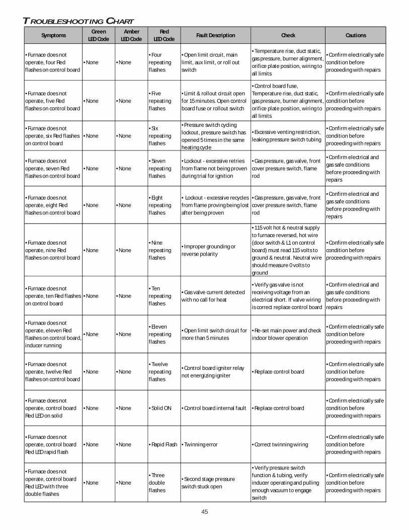
45
TROUBLESHOOTING CHARTAssociatedLED Code2Symptoms
Green LED Code
AmberLED Code
RedLED Code
Fault Description Check Cautions
•Furnace does not operate, four Red flashes on control board
•None •None•Four repeating flashes
•Open limit circuit, main limit, aux limit, or roll out switch
•Temperature rise, duct static, gas pressure, burner alignment, orifice plate position, wiring to all limits
•Confirm electrically safe condition before proceeding with repairs
•Furnace does not operate, five Red flashes on control board
•None •None•Five repeating flashes
•Limit & rollout circuit open for 15 minutes. Open control board fuse or rollout switch
•Control board fuse, Temperature rise, duct static, gas pressure, burner alignment, orifice plate position, wiring to all limits
•Confirm electrically safe condition before proceeding with repairs
•Furnace does not operate, six Red flashes on control board
•None •None•Six repeating flashes
•Pressure switch cycling lockout, pressure switch has opened 5 times in the same heating cycle
•Excessive venting restriction, leaking pressure switch tubing
•Confirm electrically safe condition before proceeding with repairs
•Furnace does not operate, seven Red flashes on control board
•None •None•Seven repeating flashes
•Lockout - excessive retries from flame not being proven during trial for ignition
•Gas pressure, gas valve, front cover pressure switch, flame rod
•Confirm electrical and gas safe conditions before proceeding with repairs
•Furnace does not operate, eight Red flashes on control board
•None •None•Eight repeating flashes
• Lockout - excessive recycles from flame proving being lost after being proven
•Gas pressure, gas valve, front cover pressure switch, flame rod
•Confirm electrical and gas safe conditions before proceeding with repairs
•Furnace does not operate, nine Red flashes on control board
•None •None•Nine repeating flashes
•Improper grounding or reverse polarity
•115 volt hot & neutral supply to furnace reversed, hot wire (door switch & L1 on control board) must read 115 volts to ground & neutral. Neutral wire should measure 0 volts to ground
•Confirm electrically safe condition before proceeding with repairs
•Furnace does not operate, ten Red flashes on control board
•None •None•Ten repeating flashes
•Gas valve current detected with no call for heat
•Verify gas valve is not receiving voltage from an electrical short. If valve wiring is correct replace control board
•Confirm electrical and gas safe conditions before proceeding with repairs
•Furnace does not operate, eleven Red flashes on control board, inducer running
•None •None•Eleven repeating flashes
•Open limit switch circuit for more than 5 minutes
•Re-set main power and check indoor blower operation
•Confirm electrically safe condition before proceeding with repairs
•Furnace does not operate, twelve Red flashes on control board
•None •None•Twelve repeating flashes
•Control board igniter relay not energizing igniter
•Replace control board•Confirm electrically safe condition before proceeding with repairs
•Furnace does not operate, control board Red LED on solid
•None •None •Solid ON •Control board internal fault •Replace control board•Confirm electrically safe condition before proceeding with repairs
•Furnace does not operate, control board Red LED rapid flash
•None •None •Rapid Flash •Twinning error •Correct twinning wiring•Confirm electrically safe condition before proceeding with repairs
•Furnace does not operate, control board Red LED with three double flashes
•None •None•Three double flashes
•Second stage pressure switch stuck open
•Verify pressure switch function & tubing, verify inducer operating and pulling enough vacuum to engage switch
•Confirm electrically safe condition before proceeding with repairs

46
HIG
H V
OLT
AG
E!
Dis
co
nn
ec
t A
LL
po
we
r b
efo
re s
erv
icin
g o
r in
sta
llin
g t
his
un
it.
Mu
ltip
lep
ow
er
so
urc
es
ma
y b
e p
res
en
t. F
ail
ure
to
do
so
ma
y c
au
se
pro
pe
rty
da
ma
ge
, p
ers
on
al i
nju
ry o
r d
eath
.
Wiring is subject to change. Always refer to the wiring diagram on the unit for the most up-to-date wiring.
WIRING DIAGRAM
GN
GND
COLOR CODES:
GN GREEN
RD REDGY GRAY
PU PURPLE
PK PINK
BK BLACK
BL BLUEWH WHITEBR BROWN
YL YELLOWOR ORANGE
GND
BK
RD
RD
GN
GN
24VA
C
115VA
C
GND
GR
D
BK
YLO Y W1 W2 R G C TWIN
0140F02011-A
BRPK
GY
OR
GN
BL
YL
S2
S1
BK
HU
MX-FM
RL1C
IRC
-HE
AC
-H
5
21
43
24 V 3 AFUSE
NEUTRAL
DIAGNOSTIC
LED’S
5 CIR
CU
IT CO
NN
EC
TOR
10
63
4
52
7
11
1
12
8
9
FRONT COVERPRESSURE SWITCH
NO
C
FUSE 3 A
MICROTO
PS2 (2)
TR (9)
G
HI
C
TH (5)
24V TH
ER
MO
STA
T CO
NN
EC
TION
S
VALVEGAS
W2
TRANSFORMER
HLI (6)
Y2
Y1 HLO (11)
GND (4)
O
MVL (7)
NO
W1
C
R
CONTROLSAUTO RESET AUXILIARY LIMIT
LIMIT CONTROLSMANUAL RESET ROLLOUTPRESS. SWTICH
HIGH FIRE
C
SWITCHLOW FIRE PRESS.
MVH (1)
DEHUM
GND
PS1 (12)
LIMIT CONTROLAUTO RESET PRIMARY24 VAC
NO
PM
MVC (8)
INTEGRATED CONTROL MODULE
C
BLWR
AIRINDOOR
CIRCULATOR
RTO
MICROTO
TO+VDC
EAC
HUMIDIFIER
ID
NEUTRAL
WIRING TO UNIT
L
INTE
GR
ATE
D C
ON
TRO
L MO
DU
LE
HOT SURFACE
GND
BLWR
NEUTRAL
WARNING:
GROUNDED.
OVERCURRENT PROTECTION DEVICE
MUST BE PROPERLY
SWITCH
NEUTRAL
ELECTRONIC
AIR
IGN
IND HI
DISCONNECT
FS
POLARIZED AND
NEUTRAL
LINE
NEUTRAL
JUNCTION BOX
BLWR
IND LO
N
INDOOR
AIR CLEANER
HUM
DOOR
NEUTRAL
INTE
GR
ATE
D C
ON
TRO
L MO
DU
LE
TO 115VAC/ 1� /60 HZ POWER SUPPLY WITH
115 VAC
HUM-OUT
IGNITER
CIRCULATOR
BEFORE SERVICING.
FLAME SENSOR
DISCONNECT POWER
LINE
GND
T4
T1T2
OR
BR
BK W
HW
HW
HW
H
PU
GY
YL
OR
BR
PK
RD
WH B
K
PU
GY
BR
OR
RDBK
ORBL
RD
WH
WH
T3
CO
M
LINE
NO
LIMIT CONTROLAUXILIARYAUTO RESET
PK
WARNING:DISCONNECT
TRA
NS
FOR
ME
R40 V
A
PU
GY
NNO
3
BR
1
SWITCHPRESSURELOW FIRE
SENSORFLAME
PRESSURE SWITCHFRONT COVER
C TO UNIT MUST BE
BL
RD
AND GROUNDED.
1
JUN
CTIO
N BO
X
WH
SWITCH (PRESS.)
FIELD SPLICEFIELD GND
3
GN
BL
BRWH
NO
LIMIT CONTROLAUTO RESET PRIMARY
WH
1
OR
30 kBTU AND 40 kBTU)CONTROLS (SINGLE CONTROL ON
MANUAL RESET ROLLOUT LIMIT
WH
L
PU
GY
BK
SWITCH ASSEMBLYID BLOWER TWO-STAGE PRESSURE
OR
WH
SERVICING. WIRING
EQUIPMENT GND
INTERNAL TO
SWITCHPRESSUREHIGH FIRE
PROT. DEVICE
INTEGRATED CONTROL
PK
PU
PLUG CONNECTION
2
4
BK
C
DOOR OPEN)(OPEN WHENDOOR SWITCHCOMPARTMENTBLOWER
SWITCH (TEMP.)
GND
1
BLOWERCIRCULATOR
JUNCTION
OR
40 VA
� /60 HZ
DISCONNECT
(WHITE RODGERS)GAS VALVETWO STAGE
OVERCURRENT
CONNECTOR2 CIRCUIT
LOW VOLTAGE (24V)
YL
GND
WH
CH
ASS
IS G
RO
UN
D2
3
IGNITERSURFACE
HOT
2
YL
PU
C
2
C
BLOWERDRAFT
INDUCED
BK
PM
BK
BLOWER COMPARTMENT
115 VAC/ 1
OVERCURRENT
BK
HARNESSECM MTR
HI
TERMINAL
OR
POWER BEFORE
IGNITER
RD
BK
TO
RD
POWER SUPPLY WITH
BURNER COMPARTMENT
PROTECTION DEVICE
PROPERLY POLARIZED
RDBK
ORBL
LOW VOLTAGE FIELDHI VOLTAGE (115V)HI VOLTAGE FIELD
RAPID = TWINNING ERROR
STEADY ON = INTERNAL GV ERROR, MICRO AND FREQUENCY CHECK
1 FLASH = FLAME SENSED WHEN NO FLAME SHOULD BE PRESENT
4 FLASHES = OPEN LIMIT SWITCH
0
4
3
2
1
RED LED FLASH CODE
2 FLASHES = PRESSURE SWITCH STUCK CLOSED/INDUCER ERROR
3 FLASHES = 1ST STAGE PRESSURE SWITCH STUCKCLOSED/INDUCER ERROR
5 FLASHES = OPEN ROLLOUT/OPEN FUSE DETECTED
6 FLASHES = PRESSURE SWITCH CYCLE LOCKOUT
7 FLASHES = EXTERNAL LOCKOUT (RETRIES)
9
6
5
7
8 8 FLASHES = EXTERNAL LOCKOUT (RECYCLES)
9 FLASHES + GROUNDING OR REVERSED POLARITY
10 FLASHES = GAS FLOW WITH NO CALL FOR HEAT
11 FLASHES = LIMIT SWITCH OPEN-BLOWER FAILURE
12 FLASHES = IGNITOR RELAY FAILURE
11
10
12
3 DOUBLE FLASHES = 2ND STAGE PRESSURE SWITCHSTUCK OPEN/INDUCER ERROR
3 FLASHES = W2 PRESENT WITH NO W1
2 FLASHES = NORMAL OPERATION WITHCALL FOR 2ND STAGE HEAT
1 FLASH = NORMAL OPERATION WITH CALL FOR1ST STAGE HEAT (W1)
2
4
3
1
4 FLASHES = Y PRESENT WITH NO G CALL, YLOPRESENT WITH NO G CALL
AMBER LED FLASH CODE
RAPID = LOW FLAME SENSE CURRENT
RAPID = NORMAL OPERATION WITH CALL FOR FAN (G)
STEADY ON = STANDBY
1 FLASH = NORMAL OPERATION WITH CALL FORLOW STAGE COOL (YLO + G)
0
2
1
GREEN LED FLASH CODE
2 FLASHES = NORMAL OPERATION WITH CALL FOR HIGHSTAGE COOL/ OR SINGLE STAGE COOLING (Y + G)
0
1. SET HEAT ANTICIPATOR ON ROOM THERMOSTAT AT 0.7 AMPS.NOTES:
$
2. MANUFACTURER’S SPECIFIED REPLACEMENT PARTS MUST BE USEDWHEN SERVICING.
MUST BE REPLACED IT MUST BE REPLACED WITH WIRING MATERIALHAVING A TEMPERATURE RATING OF AT LEAST 105 C. USE COPPERCONDUCTORS ONLY.
4. UNIT MUST BE PERMANENTLY GROUNDED AND CONFORM TO N.E.C.AND LOCAL CODES.
5. TO RECALL THE LAST 6 FAULTS, MOST RECENT TO LEAST RECENT,DEPRESS SWITCH FOR MORE THAN 2 SECONDS WHILE IN STANDBY(NO THERMOSTAT INPUTS)
3. IF ANY OF THE ORIGINAL WIRE AS SUPPLIED WITH THE FURNACE

47
For all side wall horizontally vented gas fueled equipment in-stalled in every dwelling, building or structure used in whole orin part for residential purposes, including those owned or op-erated by the Commonwealth and where the side wall exhaustvent termination is less than seven (7) feet above finished gradein the area of the venting, including but not limited to decksand porches, the following requirements shall be satisfied:
1. INSTALLATION OF CARBON MONOXIDE DETECTORS. At thetime of installation of the side wall horizontal vented gasfueled equipment, the installing plumber or gasfitter shallobserve that a hard wired carbon monoxide detector withan alarm and battery back-up is installed on the floor levelwhere the gas equipment is to be installed. In addition, theinstalling plumber or gasfitter shall observe that a batteryoperated or hard wired carbon monoxide detector with analarm is installed on each additional level of the dwelling,building or structure served by the side wall horizontalvented gas fueled equipment. It shall be the responsibilityof the property owner to secure the services of qualified licensed professionals for the installation of hard wired carbonmonoxide detectors
a. In the event that the side wall horizontally vented gas fueled equipment is installed in a crawl space or an attic, the hardwired carbon monoxide detector with alarm and battery back-up may be installed on the next adjacent floor level.
b. In the event that the requirements of this subdivision can not be met at the time of completion of installation, the ownershall have a period of thirty (30) days to comply with the above requirements; provided, however, that during said thirty (30)day period, a battery operated carbon monoxide detector with an alarm shall be installed.
2. APPROVED CARBON MONOXIDE DETECTORS. Each carbon monoxide detector as required in accordance with the aboveprovisions shall comply with NFPA 720 and be ANSI/UL 2034 listed and IAS certified.
3. SIGNAGE. A metal or plastic identification plate shall be permanently mounted to the exterior of the building at a minimumheight of eight (8) feet above grade directly in line with the exhaust vent terminal for the horizontally vented gas fueledheating appliance or equipment. The sign shall read, in print size no less than one-half (1/2) inch in size, “GAS VENT DIRECTLYBELOW. KEEP CLEAR OF ALL OBSTRUCTIONS”.
4. INSPECTION. The state or local gas inspector of the side wall horizontally vented gas fueled equipment shall not approve theinstallation unless, upon inspection, the inspector observes carbon monoxide detectors and signage installed in accordancewith the provisions of 248 CMR 5.08(2)(a)1 through 4.
EXEMPTIONS
The following equipment is exempt from 248 CMR 5.08(2)(a)1 through 4:1. The equipment listed in Chapter 10 entitled “Equipment Not Required To Be Vented” in the most current edition of NFPA 54
as adopted by the Board; and2. Product Approved side wall horizontally vented gas fueled equipment installed in a room or structure separate from the
dwelling, building or structure used in whole or in part for residential purposes.(c) MANUFACTURER REQUIREMENTS - GAS EQUIPMENT VENTING SYSTEM PROVIDED. When the manufacturer of Product Approved
side wall horizontally vented gas equipment provides a venting system design or venting system components with theequipment, the instructions provided by the manufacturer for installation of the equipment and the venting system shallinclude:
1. Detailed instructions for the installation of the venting system design or the venting system components; and2. A complete parts list for the venting system design or venting system.
(d) MANUFACTURER REQUIREMENTS - GAS EQUIPMENT VENTING SYSTEM NOT PROVIDED. When the manufacturer of a ProductApproved side wall horizontally vented gas fueled equipment does not provide the parts for venting the flue gases, butidentifies “special venting systems”, the following requirements shall be satisfied by the manufacturer:
1. The referenced “special venting system” instructions shall be included with the appliance or equipment installation instructions;and
2. The “special venting systems” shall be Product Approved by the Board, and the instructions for that system shall include aparts list and detailed installation instructions.
(e) A copy of all installation instructions for all Product Approved side wall horizontally vented gas fueled equipment, all ventinginstructions, all parts lists for venting instructions, and/or all venting design instructions shall remain with the appliance orequipment at the completion of the installation.
SPECIAL INSTRUCTIONS FOR PRODUCTS INSTALLED
IN THE STATE OF MASSACHUSETTS
VENT/FLUETEE
COMBUSTIONAIR INTAKE.
DISTANCE BETWEENCOMBUSTION AIR
INTAKE AND GRADE
DISTANCE BETWEENVENT AND GRADE

48
NOTE: SPECIFICATIONS AND PERFORMANCE DATA LISTED HEREIN ARE SUBJECT TO CHANGE WITHOUT NOTICE.Visit our web sites at www.goodmanmfg.com or www.amana-hac.com for information on:
• Products • Parts• Warranties • Contractor Programs and Training• Customer Services • Financing Options
5151 San Felipe Suite 500Houston, TX 77056
www.goodmanmfg.com • www.amana-hac.com© 2014 Goodman Manufacturing Company, L.P.
is a registered trademark of Maytag Corporation or its related companies and is usedunder license to Goodman Company, L.P., Houston, TX. All rights reserved.