Embed Size (px)
Citation preview

5151 San Felipe Suite 500Houston, TX 77056
www.goodmanmfg.com • www.amana-hac.com© 2014 - 2016 Goodman Manufacturing Company, L.P.
*MEC96UPFLOW / HORIZONTAL TWO-STAGE
GAS FURNACE
IOG-2011F04/2016
(Type FSP CATEGORY IV Director Non Direct Vent Air Furnace)
These furnaces comply with requirements em-bodied in the American National Standard / Na-tional Standard of Canada ANSI Z21.47·CSA-2.3Gas Fired Central Furnaces.
Installer:Affix all manuals
adjacent to the unit.
As a professional installer you have an obligation to knowthe product better than the customer. This includes all safetyprecautions and related items.
Prior to actual installation, thoroughly familiarize yourselfwith this Instruction Manual. Pay special attention to allsafety warnings. Often during installation or repair it ispossible to place yourself in a position which is morehazardous than when the unit is in operation.
Remember, it is your responsibility to install the productsafely and to know it well enough to be able to instruct acustomer in its safe use.
Safety is a matter of common sense...a matter of thinkingbefore acting. Most dealers have a list of specific goodsafety practices...follow them.
The precautions listed in this Installation Manual are intendedas supplemental to existing practices. However, if there isa direct conflict between existing practices and the contentof this manual, the precautions listed here take precedence.
RECOGNIZE THIS SYMBOL
AS A SAFETY PRECAUTION.
*NOTE: Please contact your distributor or our website forthe applicable Specification Sheet referred to in this manual.
TABLE OF CONTENTS
is a registered trademark of Maytag Corporation or its related companies and is used under license. All rights reserved.
SAFETY CONSIDERATIONS .................................... 2SHIPPING INSPECTION ............................................ 4ELECTROSTATIC DISCHARGE (ESD) PRECAUTIONS ................... 4TO THE INSTALLER .............................................. 5
PRODUCT DESCRIPTION ......................................... 5FEATURES ....................................................... 5
PRODUCT APPLICATION ......................................... 5LOCATION REQUIREMENTS & CONSIDERATIONS ........... 6
CLEARANCES AND ACCESSIBILITY ................................... 7EXISTING FURNACE REMOVAL ..................................... 8THERMOSTAT LOCATION .......................................... 8COMBUSTION & VENTILATION AIR REQUIREMENTS .................. 9
INSTALLATION POSITIONS ...................................... 9HORIZONTAL APPLICATIONS & CONSIDERATIONS ..................... 9FURNACE SUSPENSION ..........................................10FRONT COVER PRESSURE SWITCH TUBE LOCATION ................10DRAIN TRAP AND LINES .........................................10HORIZONTAL FURNACE LEVELING ................................10ALTERNATE ELECTRICAL AND GAS LINE CONNECTIONS .............10DRAIN PAN ....................................................10FREEZE PROTECTION ............................................10
PROPANE GAS/HIGH ALTITUDE INSTALLATIONS ..........10VENT/FLUE PIPE & COMBUSTION AIR PIPE .................11
DUAL CERTIFICATION: NON-DIRECT/DIRECT VENT ................11MATERIALS AND JOINING METHODS ..............................11PROPER VENT/FLUE AND COMBUSTION AIR PIPING PRACTICES .....12TERMINATION LOCATIONS ........................................12CANADIAN VENTING REQUIREMENTS ..............................13STANDARD FURNACE CONNECTIONS ..............................13VENT/FLUE PIPE ..............................................13NON-DIRECT VENT (SINGLE PIPE) PIPING ........................15VENT/INTAKE TERMINATIONS FOR INSTALLATION
OF MULTIPLE DIRECT VENT FURNACES ........................18CONCENTRIC VENT TERMINATION .................................18SIDE WALL VENT KIT ..........................................18
CONDENSATE DRAIN LINES & DRAIN TRAP .................18GENERAL DRAIN INFORMATION ...................................18FIELD SUPPLIED DRAIN .........................................19UPFLOW MODEL INSTALLED VERTICALLY ..........................19DRAIN EXITING RIGHT SIDE .....................................19DRAIN EXITING LEFT SIDE ......................................20UPFLOW MODEL INSTALLED HORIZONTALLY
WITH RIGHT SIDE DOWN .....................................20UPFLOW MODEL INSTALLED HORIZONTALLY
WITH LEFT SIDE DOWN ......................................20
2
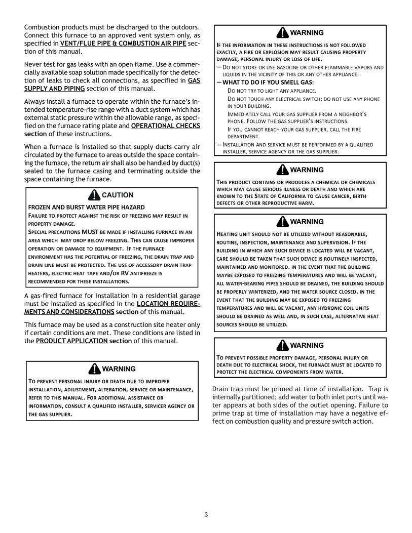
SAFETY CONSIDERATIONS
Adhere to the following warnings and cautions when installing,adjusting, altering, servicing, or operating the furnace. Toensure proper installation and operation, thoroughly read thismanual for specifics pertaining to the installation and applica-tion of this product.
This furnace is manufactured for use with natural gas. It maybe field converted to operate on L.P. gas by using the appro-priate L.P. conversion kit listed in the PROPANE GAS/HIGH ALTITUDE INSTALLATIONS section of this manual
Install this furnace only in a location and position as specified in LOCATION REQUIREMENTS & CONSIDERATIONS section andINSTALLATION POSITIONS section of this manual.
Provide adequate combustion and ventilation air to the furnace as specified in COMBUSTION & VENTILATION AIR REQUIRE-MENTS section of this manual.
GOODMAN WILL NOT BE RESPONSIBLE FOR ANY INJURY OR PROPERTY DAMAGE ARISING FROM IMPROPER SERVICE OR SERVICE PROCEDURES. IF YOU INSTALL OR PERFORM SERVICE ON THIS UNIT, YOU ASSUME RESPONSIBILITY FOR ANY PERSONAL INJURY OR PROPERTY DAMAGE WHICH MAY RESULT. MANY JURISDICTIONS REQUIRE A LICENSE TO INSTALL OR SERVICE HEATING AND AIR CONDITIONING EQUIPMENT.
WARNING
ELECTRICAL CONNECTIONS ...................................21WIRING HARNESS ...............................................21115 VOLT LINE CONNECTIONS ..................................21JUNCTION BOX RELOCATION .....................................2124 VOLT THERMOSTAT WIRING ..................................22SINGLE-STAGE HEATING THERMOSTAT APPLICATION ................23FOSSIL FUEL APPLICATIONS ......................................23TWINNING .....................................................23115 VOLT LINE CONNECTION OF ACCESSORIES
(HUMIDIFIER AND ELECTRONIC AIR CLEANER) ..................23GAS SUPPLY AND PIPING .......................................24
HIGH ALTITUDE DERATE .........................................24PROPANE GAS CONVERSION .....................................24GAS PIPING CONNECTIONS ......................................25PROPANE GAS TANKS AND PIPING................................26
CIRCULATING AIR & FILTERS ..................................27DUCT WORK - AIR FLOW .......................................27CHECKING DUCT STATIC .........................................27BOTTOM RETURN AIR OPENING [UPFLOW MODELS] ..............28FILTERS - READ THIS SECTION BEFORE INSTALLING
THE RETURN AIR DUCT WORK................................28UPRIGHT INSTALLATIONS .........................................29HORIZONTAL INSTALLATIONS ......................................30
STARTUP PROCEDURE & ADJUSTMENT ......................30DRAIN TRAP PRIMING ...........................................30FURNACE OPERATION ...........................................30GAS SUPPLY PRESSURE MEASUREMENT ...........................31GAS MANIFOLD PRESSURE MEASUREMENT AND ADJUSTMENT .......32GAS INPUT RATE MEASUREMENT (NATURAL GAS ONLY) ...........32TEMPERATURE RISE .............................................33CIRCULATOR BLOWER SPEEDS ...................................33DIP SWITCH SETTINGS .........................................34BLOWER HEAT OFF DELAY TIMINGS .............................40
NORMAL SEQUENCE OF OPERATION .........................40POWER UP ....................................................40HEATING MODE ................................................40COOLING MODE ................................................41FAN ONLY MODE ..............................................41
OPERATIONAL CHECKS .........................................41SAFETY CIRCUIT DESCRIPTION ...............................41
INTEGRATED CONTROL MODULE .................................41PRIMARY LIMIT .................................................41AUXILIARY LIMIT ................................................41ROLLOUT LIMIT ................................................42PRESSURE SWITCHES ............................................42FLAME SENSOR ................................................42TROUBLESHOOTING .............................................42ELECTROSTATIC DISCHARGE (ESD) PRECAUTIONS ..................42CHECKING FLAME SENSOR ......................................42LIMIT FAULT CODES ............................................42DIAGNOSTIC CHART .............................................43FAULT RECALL .................................................43RESETTING FROM LOCKOUT .....................................44
MAINTENANCE ...................................................44ANNUAL INSPECTION ............................................44FILTERS ........................................................44BURNERS ......................................................45INDUCED DRAFT AND CIRCULATOR BLOWERS ......................45CONDENSATE TRAP AND DRAIN SYSTEM (QUALIFIED SERVICER ONLY)45FLAME SENSOR (QUALIFIED SERVICER ONLY) ....................45FLUE PASSAGES (QUALIFIED SERVICER ONLY) ....................45
BEFORE LEAVING AN INSTALLATION .........................45REPAIR AND REPLACEMENT PARTS ...........................46TROUBLESHOOTING CHART ...................................47WIRING DIAGRAM ...............................................49SPECIAL INSTRUCTIONS FOR PRODUCTS INSTALLED
IN THE STATE OF MASSACHUSETTS ..................50
3
Combustion products must be discharged to the outdoors.Connect this furnace to an approved vent system only, asspecified in VENT/FLUE PIPE & COMBUSTION AIR PIPE sec-tion of this manual.
Never test for gas leaks with an open flame. Use a commer-cially available soap solution made specifically for the detec-tion of leaks to check all connections, as specified in GASSUPPLY AND PIPING section of this manual.
Always install a furnace to operate within the furnace’s in-tended temperature-rise range with a duct system which hasexternal static pressure within the allowable range, as speci-fied on the furnace rating plate and OPERATIONAL CHECKSsection of these instructions.
When a furnace is installed so that supply ducts carry aircirculated by the furnace to areas outside the space contain-ing the furnace, the return air shall also be handled by duct(s)sealed to the furnace casing and terminating outside thespace containing the furnace.
A gas-fired furnace for installation in a residential garagemust be installed as specified in the LOCATION REQUIRE-MENTS AND CONSIDERATIONS section of this manual.
This furnace may be used as a construction site heater onlyif certain conditions are met. These conditions are listed inthe PRODUCT APPLICATION section of this manual.
TO PREVENT PERSONAL INJURY OR DEATH DUE TO IMPROPER INSTALLATION, ADJUSTMENT, ALTERATION, SERVICE OR MAINTENANCE, REFER TO THIS MANUAL. FOR ADDITIONAL ASSISTANCE OR INFORMATION, CONSULT A QUALIFIED INSTALLER, SERVICER AGENCY OR THE GAS SUPPLIER.
WARNING
FROZEN AND BURST WATER PIPE HAZARDFAILURE TO PROTECT AGAINST THE RISK OF FREEZING MAY RESULT IN PROPERTY DAMAGE.SPECIAL PRECAUTIONS MUST BE MADE IF INSTALLING FURNACE IN AN AREA WHICH MAY DROP BELOW FREEZING. THIS CAN CAUSE IMPROPER OPERATION OR DAMAGE TO EQUIPMENT. IF THE FURNACE ENVIRONMENT HAS THE POTENTIAL OF FREEZING, THE DRAIN TRAP AND DRAIN LINE MUST BE PROTECTED. THE USE OF ACCESSORY DRAIN TRAP HEATERS, ELECTRIC HEAT TAPE AND/OR RV ANTIFREEZE IS RECOMMENDED FOR THESE INSTALLATIONS.
CAUTION
IF THE INFORMATION IN THESE INSTRUCTIONS IS NOT FOLLOWED EXACTLY, A FIRE OR EXPLOSION MAY RESULT CAUSING PROPERTYDAMAGE, PERSONAL INJURY OR LOSS OF LIFE.
DO NOT STORE OR USE GASOLINE OR OTHER FLAMMABLE VAPORS AND LIQUIDS IN THE VICINITY OF THIS OR ANY OTHER APPLIANCE.
DO NOT TRY TO LIGHT ANY APPLIANCE.DO NOT TOUCH ANY ELECTRICAL SWITCH; DO NOT USE ANY PHONE IN YOUR BUILDING.IMMEDIATELY CALL YOUR GAS SUPPLIER FROM A NEIGHBOR’S PHONE. FOLLOW THE GAS SUPPLIER’S INSTRUCTIONS.IF YOU CANNOT REACH YOUR GAS SUPPLIER, CALL THE FIRE DEPARTMENT.
INSTALLATION AND SERVICE MUST BE PERFORMED BY A QUALIFIED INSTALLER, SERVICE AGENCY OR THE GAS SUPPLIER.
WHAT TO DO IF YOU SMELL GAS:
WARNING
THIS PRODUCT CONTAINS OR PRODUCES A CHEMICAL OR CHEMICALS WHICH MAY CAUSE SERIOUS ILLNESS OR DEATH AND WHICH ARE KNOWN TO THE STATE OF CALIFORNIA TO CAUSE CANCER, BIRTH DEFECTS OR OTHER REPRODUCTIVE HARM.
WARNING
HEATING UNIT SHOULD NOT BE UTILIZED WITHOUT REASONABLE, ROUTINE, INSPECTION, MAINTENANCE AND SUPERVISION. IF THE BUILDING IN WHICH ANY SUCH DEVICE IS LOCATED WILL BE VACANT, CARE SHOULD BE TAKEN THAT SUCH DEVICE IS ROUTINELY INSPECTED, MAINTAINED AND MONITORED. IN THE EVENT THAT THE BUILDING MAYBE EXPOSED TO FREEZING TEMPERATURES AND WILL BE VACANT, ALL WATER-BEARING PIPES SHOULD BE DRAINED, THE BUILDING SHOULD BE PROPERLY WINTERIZED, AND THE WATER SOURCE CLOSED. IN THE EVENT THAT THE BUILDING MAY BE EXPOSED TO FREEZING TEMPERATURES AND WILL BE VACANT, ANY HYDRONIC COIL UNITS SHOULD BE DRAINED AS WELL AND, IN SUCH CASE, ALTERNATIVE HEAT SOURCES SHOULD BE UTILIZED.
WARNING
TO PREVENT POSSIBLE PROPERTY DAMAGE, PERSONAL INJURY OR DEATH DUE TO ELECTRICAL SHOCK, THE FURNACE MUST BE LOCATED TO PROTECT THE ELECTRICAL COMPONENTS FROM WATER.
WARNING
Drain trap must be primed at time of installation. Trap isinternally partitioned; add water to both inlet ports until wa-ter appears at both sides of the outlet opening. Failure toprime trap at time of installation may have a negative ef-fect on combustion quality and pressure switch action.
4
SHIPPING INSPECTION
All units are securely packed in shipping containers tested accord-ing to International Safe Transit Association specifications. Thecarton must be checked upon arrival for external damage. If dam-age is found, a request for inspection by carrier’s agent must bemade in writing immediately.
The furnace must be carefully inspected on arrival for damage andbolts or screws which may have come loose in transit. In the eventof damage the consignee should:1. Make a notation on delivery receipt of any visible damage to
shipment or container.2. Notify carrier promptly and request an inspection.3. With concealed damage, carrier must be notified as soon as
possible - preferably within five days.4. File the claim with the following support documents within a
nine month statute of limitations.• Original or certified copy of the Bill of Lading, or indemnity bond.• Original paid freight bill or indemnity in lieu thereof.• Original or certified copy of the invoice, showing trade and other discounts or reductions.• Copy of the inspection report issued by carrier’s representative at the time damage is reported to carrier.
The carrier is responsible for making prompt inspection of damage and for a thorough investigation of each claim. The distributor ormanufacturer will not accept claims from dealers for transportation damage.
ELECTROSTATIC DISCHARGE (ESD) PRECAUTIONS
NOTE: Discharge your body’s static electricity before touching unit. An electrostatic discharge can adversely affect electricalcomponents.
Use the following precautions during furnace installation and servicing to protect the integrated control module from damage. Byputting the furnace, the control, and the person at the same electrostatic potential, these steps will help avoid exposing theintegrated control module to electrostatic discharge. This procedure is applicable to both installed and non-installed (ungrounded)furnaces.1. Disconnect all power to the furnace. Do not touch the integrated control module or any wire connected to the control prior to
discharging your body’s electrostatic charge to ground.2. Firmly touch a clean, unpainted, metal surface of the furnaces near the control. Any tools held in a person’s hand during
grounding will be discharged.
SHOULD OVERHEATING OCCUR OR THE GAS SUPPLY FAIL TO SHUT OFF, TURN OFF THE MANUAL GAS SHUTOFF VALVE EXTERNAL TO THE FURNACE BEFORE TURNING OFF THE ELECTRICAL SUPPLY.
WARNING
POSSIBLE PROPERTY DAMAGE, PERSONAL INJURY OR DEATH DUE TO FIRE, EXPLOSION, SMOKE, SOOT, CONDENSATION, ELECTRICAL SHOCK OR CARBON MONOXIDE MAY RESULT FROM IMPROPER INSTALLATION, REPAIR OPERATION, OR MAINTENANCE OF THIS PRODUCT.
WARNING
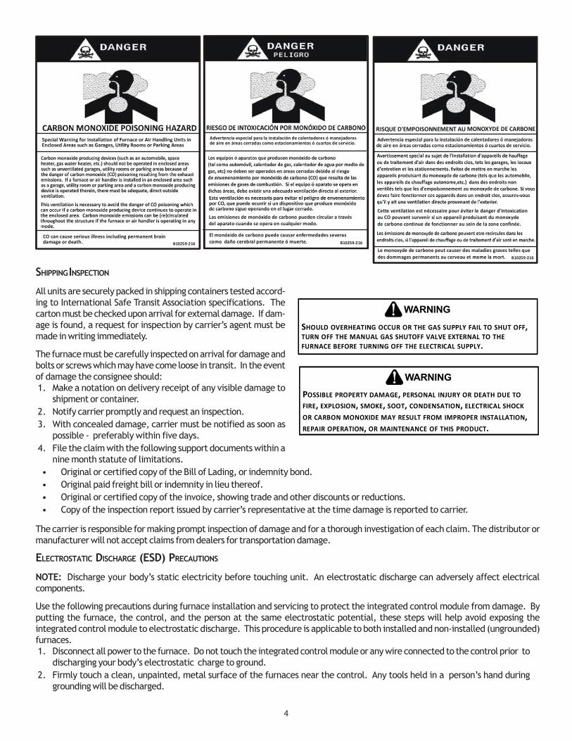
B10259-216CO can cause serious illness including permanent braindamage or death.
Advertencia especial para la instalación de calentadores ó manejadoras de aire en áreas cerradas como estacionamientos ó cuartos de servicio.
B10259-216
El monóxido de carbono puede causar enfermedades severas como daño cerebral permanente ó muerte.
Las emisiones de monóxido de carbono pueden circular a travésdel aparato cuando se opera en cualquier modo.
B10259-216
RISQUE D'EMPOISONNEMENT AU MONOXYDE DE CARBONE
Le monoxyde de des
carbone peut causer des maladies graves telles quedommages permanents au cerveau et meme la mort.
Cette ventilation est nécessaire pour éviter le danger d'intoxicationau CO pouvant survenir si un appareil produisant du monoxyde de carbone continue de fonctionner au sein de la zone confinée.

5
3. Service integrated control module or connecting wiring following the discharge process in step 2. Use caution not to rechargeyour body with static electricity; (i.e., do not move or shuffle your feet, do not touch ungrounded objects, etc.). If you comein contact with an ungrounded object, repeat step 2 before touching control or wires.
4. Discharge your body to ground before removing a new control from its container. Follow steps 1 through 3 if installing thecontrol on a furnace. Return any old or new controls to their containers before touching any ungrounded object.
TO THE INSTALLER
Before installing this unit, please read this manual thoroughly tofamiliarize yourself with specific items which must be adhered to,including but not limited to: unit maximum external static pres-sure, gas pressures, BTU input rating, proper electrical connec-tions, circulating air temperature rise, minimum or maximum CFM,and motor speed connections.
PRODUCT DESCRIPTION
FEATURES
The *MEC96 furnace may be installed upflow or horizontally with left or right side down. The *MEC96 two-stage gas furnacefeatures a multi-speed ECM indoor fan motor, two heating inputs (W1 & W2), two cooling inputs (YLO & Y) and a two stagegas valve. A single stage heating thermostat may also be used in conjunction with timed transition to high fire by the furnaceintegrated control board.
PRODUCT APPLICATION
This furnace is primarily designed for residential home-heating applications. It is NOT designed or certified for use in mobile homes,trailers or recreational vehicles. Neither is it designed or certified for outdoor applications. The furnace must be installed indoors(i.e., attic space, crawl space, or garage area provided the garage area is enclosed with an operating door).
This furnace can be used in the following non-industrial commercial applications:
Schools, Office buildings, Churches, Retail stores, Nursing homes, Hotels/motels, Common or office areas
In such applications, the furnace must be installed with the following stipulations:• It must be installed per the installation instructions provided and per local and national codes.• It must be installed indoors in a building constructed on site.• It must be part of a ducted system and not used in a free air delivery application.• It must not be used as a “make-up” air unit.• It must be installed as a two-pipe system for combustion air.• All other warranty exclusions and restrictions apply This furnace is an ETL dual-certified appliance and is appropriate for use
with natural or propane gas (NOTE: If using propane, a propane conversion kit is required).
Dual certification means that the combustion air inlet pipe is optional and the furnace can be vented as a:Non-direct vent (single pipe) central forced air furnace in which combustion air is taken from the installation area or from airducted from the outside or,Direct vent (dual pipe) central forced air furnace in which all combustion air supplied directly to the furnace burners througha special air intake system outlined in these instructions.
This furnace may be used as a construction site heater ONLY if all of the following conditions are met:• The vent system is permanently installed per these installation instructions.• A room thermostat is used to control the furnace. Fixed jumpers that provide continuous heating CANNOT be used and can
cause long term equipment damage. Bi-metal thermostats, or any thermostat affected by vibration must not be usedduring construction.
• Return air ducts are provided and sealed to the furnace.• A return air temperature range between 60ºF (16ºC) and 80ºF (27ºC) is maintained.• Air filters are installed in the system and replaced daily during construction and upon completion of construction.• The input rate and temperature rise are set per the furnace rating plate.• The furnace must be installed as a two pipe system, using 100% outside air for combustion during construction.
TO PREVENT PROPERTY DAMAGE, PERSONAL INJURY OR DEATH DUE TO FIRE, DO NOT INSTALL THIS FURNACE IN A MOBILE HOME, TRAILER, OR RECREATIONAL VEHICLE.
WARNING
6
• The furnace heat exchanger, components, duct system, air filters and evaporator coils are thoroughly cleaned following finalconstruction clean up by a qualified person.
• All furnace operating conditions (including ignition, input rate, temperature rise and venting) are verified by a qualifiedperson according to these installation instructions.
• Furnace doors must be in place on the furnace while the furnace is operating in any mode.• Damage or repairs due to failure to comply with these requirements are not covered under the warranty.
NOTE: The Commonwealth of Massachusetts requires that the following additional requirements must also be met:• Gas furnaces must be installed by a licensed plumber or gas fitter.• A T-handle gas cock must be used.• If the unit is to be installed in an attic, the passageway to and the service area around the unit must have flooring.
To ensure proper furnace operation, install, operate and maintain the furnace in accordance with these installation andoperation instructions, all local building codes and ordinances. In their absence, follow the latest edition of the National Fuel GasCode (NFPA 54/ANSI Z223.1), and/or CAN/CSA B149.1-15 Installation Codes, local plumbing or waste water codes, and otherapplicable codes.
A copy of the National Fuel Gas Code (NFPA 54/ANSI Z223.1) can be obtained from any of the following:American National Standards Institute National Fire Protection Association CSA International 25 West 43rd Street, 4th Floor 1 Batterymarch Park 8501 East Pleasant Valley
New York, NY 10036 Quincy, MA 02169-7471 Independence, OH 44131
The rated heating capacity of the furnace should be greater than or equal to the total heat loss of the area to be heated. The totalheat loss should be calculated by an approved method or in accordance with “ASHRAE Guide” or “Manual J-Load Calculations”published by the Air Conditioning Contractors of America.
A copy of the CAN/CSA B149.1-15 Installation Codes can also be obtained from:CSA International
178 Rexdale BoulevardEtobicoke, Ontario, Canada M9W 1R3
LOCATION REQUIREMENTS & CONSIDERATIONS
Follow the instructions listed below and the guidelines provided in the Combustion and Ventilation Air Requirements section whenselecting a furnace location.
TO PREVENT POSSIBLE EQUIPMENT DAMAGE, PROPERTY DAMAGE, PERSONAL INJURY OR DEATH, THE FOLLOWING BULLET POINTS MUST BE OBSERVED WHEN INSTALLING THIS UNIT.
WARNING
POSSIBLE PROPERTY DAMAGE, PERSONAL INJURY OR DEATH DUE TO FIRE, EXPLOSION, SMOKE, SOOT, CONDENSATION, ELECTRICAL SHOCK OR CARBON MONOXIDE MAY RESULT FROM IMPROPER INSTALLATION, REPAIR OPERATION, OR MAINTENANCE OF THIS PRODUCT.
WARNING
• Centrally locate the furnace with respect to the proposed or existing air distribution system.• Ensure the temperature of the return air entering the furnace is between 55°F and 100°F when the furnace is heating.• Provide provisions for venting combustion products outdoors through a proper venting system. Special consideration
should be given to vent/flue pipe routing and combustion air intake pipe when applicable. Refer to Vent/Flue Pipe andCombustion Air Pipe -Termination Locations for appropriate termination locations and to determine if the piping systemfrom furnace to termination can be accomplished within the guidelines given. NOTE: The length of flue and/or combustionair piping can be a limiting factor in the location of the furnace.
• Locate the furnace so condensate flows downwards to the drain. Do not locate the furnace or its condensate drainagesystem in any area subject to below freezing temperatures without proper freeze protection. Refer to Condensate DrainLines and Trap for further details.
• Ensure adequate combustion air is available for the furnace. Improper or insufficient combustion air can expose buildingoccupants to gas combustion products that could include carbon monoxide. Refer to Combustion and Ventilation AirRequirements.
• Set the furnace on a level floor to enable proper condensate drainage. If the floor becomes wet or damp at times, place thefurnace above the floor on a concrete base sized approximately 1-1/2" larger than the base of the furnace. Refer to theHorizontal Applications and Considerations for leveling of horizontal furnaces.
• Ensure upflow or horizontal furnaces are not installed directly on carpeting, or any other combustible material. The onlycombustible material allowed is wood.
7
• Exposure to contaminated combustion air will result in safety and performance-related problems. Do not install the furnacewhere the combustion air is exposed to the following substances:permanent wave solutions chlorinated waxes or cleaners chlorine-basedcarbon tetrachloride water softening chemicals swimming pool chemicalsdeicing salts or chemicals halogen type refrigerantscleaning solutions (such as perchloroethylene) printing inkspaint removers varnishes hydrochloric acidcements and glues antistatic fabric softeners for clothes dryers
• Seal off a non-direct vent furnace if it is installed near an area frequently contaminated by any of the above substances. Thisprotects the non-direct vent furnace from airborne contaminants. To ensure that the enclosed non-direct vent furnace hasan adequate supply of combustion air, vent from a nearby uncontaminated room or from outdoors. Refer to the Combustionand Ventilation Air Requirements for details.
• If the furnace is used in connection with a cooling coil unit, install the furnace upstream or in parallel with the cooling coilunit. Premature heat exchanger failure will result if the cooling unit is placed ahead of the furnace.For vertical applications, the minimum cooling coil width shall not be less than furnace width minus 1”.For upflow applications, the front of the coil and furnace must face the same direction.
• If the furnace is installed in a residential garage, position the furnace so that the burners and ignition source are located notless than 18 inches (457 mm) above the floor. Protect the furnace from physical damage by vehicles.
• If the furnace is installed horizontally, ensure the access doors are not on the “up/top” or “down/bottom” side of thefurnace.
• Do not connect this furnace to a chimney flue that serves a separate appliance designed to burn solid fuel.
CLEARANCES AND ACCESSIBILITY
NOTES:• For servicing or cleaning, a 24” front clearance is required.• Unit connections (electrical, flue and drain) may necessitate greater clearances than the minimum clearances listed
above.• In all cases, accessibility clearance must take precedence over clearances from the enclosure where accessibility
clearances are greater.
Installations must adhere to the clearances to combustible materi-als to which this furnace has been design certified. The minimumclearance information for this furnace is provided on the unit’sclearance label. These clearances must be permanently maintained.Clearances must also accommodate an installation’s gas, electri-cal, and drain trap and drain line connections. If the alternatecombustion air intake or vent/flue connections are used additionalclearance must be provided to accommodate these connections.Refer to Vent/Flue Pipe and Combustion Air Pipe for details.
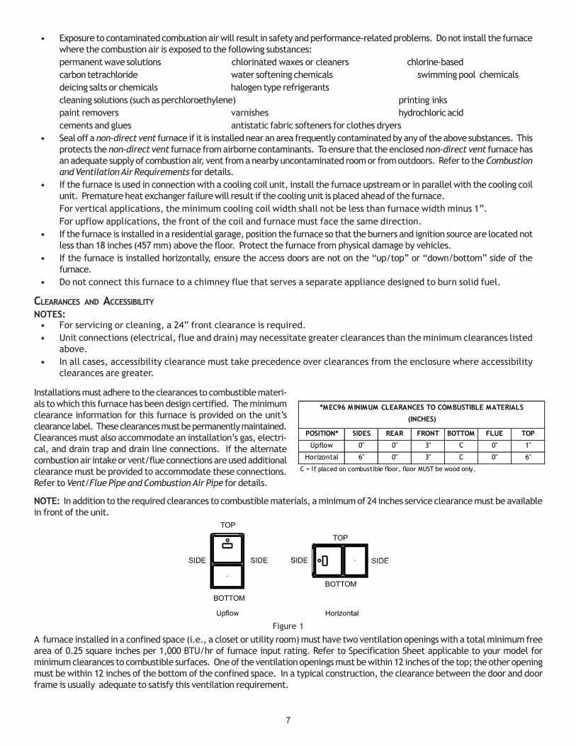
NOTE: In addition to the required clearances to combustible materials, a minimum of 24 inches service clearance must be availablein front of the unit.
TOP
BOTTOM
TOP
BOTTOM
Figure 1
A furnace installed in a confined space (i.e., a closet or utility room) must have two ventilation openings with a total minimum freearea of 0.25 square inches per 1,000 BTU/hr of furnace input rating. Refer to Specification Sheet applicable to your model forminimum clearances to combustible surfaces. One of the ventilation openings must be within 12 inches of the top; the other openingmust be within 12 inches of the bottom of the confined space. In a typical construction, the clearance between the door and doorframe is usually adequate to satisfy this ventilation requirement.
POSITION* SIDES REAR FRONT BOTTOM FLUE TOP
Upflow 0" 0" 3" C 0" 1"
Horizontal 6" 0" 3" C 0" 6"
C = If placed on combustible floor, floor MUST be wood only.
*MEC96 MINIMUM CLEARANCES TO COMBUSTIBLE MATERIALS
(INCHES)

8
EXISTING FURNACE REMOVAL
NOTE: When an existing furnace is removed from a venting system serving other appliances, the venting system may be too large toproperly vent the remaining attached appliances.
The following vent testing procedure is reproduced from the American National Standard/National Standard of Canada for Gas-Fired Central Furnaces ANSI Z21.47, CSA-2.3 latest edition Section 1.23.1.
The following steps shall be followed with each appliance connected to the venting system placed in operation, while any otherappliances connected to the venting system are not in operation:
1. Seal any unused openings in the venting system.
2. Inspect the venting system for proper size and horizontal pitch, as required by the National Fuel Gas Code, ANSI Z223.1or the Natural Gas and Propane Installation Code, CSA B149.1-15 and these instructions. Determine that there is noblockage or restriction, leakage, corrosion and other deficiencies which could cause an unsafe condition.
3. As far as practical, close all building doors and windows and all doors between the space in which the appliance(s)connected to the venting system are located and other spaces of the building.
4. Close fireplace dampers.
5. Turn on clothes dryers and any appliance not connected to the venting system. Turn on any exhaust fans, such as rangehoods and bathroom exhausts, so they shall operate at maximum speed. Do not operate a summer exhaust fan.
6. Follow the lighting instructions. Place the appliance being inspected in operation. Adjust thermostat so appliance shalloperate continuously.
7. Test for spillage from draft hood appliances at the draft hood relief opening after 5 minutes of main burner operation.Use the flame of a match or candle.
8. If improper venting is observed during any of the above tests, the venting system must be corrected in accordancewith the National Fuel Gas Code ANSI Z223.1/NFPA 54 and/or National Gas and Propane Installation Code CSA B149.1-15.
9. After it has been determined that each appliance connected to the venting system properly vents when tested asoutlined above, return doors, windows, exhaust fans, fireplace dampers and any other gas burning appliance to theirprevious conditions of use.
If resizing is required on any portion of the venting system, use the appropriate table in Appendix G in the latest edition of theNational Fuel Gas Code ANSI Z223.1 and/or CSA B149.1-15 Installation Codes.
THERMOSTAT LOCATION
The thermostat should be placed approximately five feet from the floor on a vibration-free, inside wall in an area having good aircirculation. Do not install the thermostat where it may be influenced by any of the following:
• Drafts, or dead spots behind doors, in corners, or under cabinets.• Hot or cold air from registers.• Radiant heat from the sun.• Light fixtures or other appliances.• Radiant heat from a fireplace.• Concealed hot or cold water pipes, or chimneys.• Unconditioned areas behind the thermostat, such as an outside wall.
Consult the instructions packaged with the thermostat for mounting instructions and further precautions.

9
COMBUSTION & VENTILATION AIR REQUIREMENTS
Improved construction and additional insulation in buildings havereduced heat loss by reducing air infiltration and escape arounddoors and windows. These changes have helped in reducing heat-ing/cooling costs but have created a problem supplying combus-tion and ventilation air for gas fired and other fuel burning appli-ances. Appliances that pull air out of the house (clothes dryers,exhaust fans, fireplaces, etc.) increase the problem by starving appliances for air.
House depressurization can cause back drafting or improper combustion of gas-fired appliances, thereby exposing building occu-pants to gas combustion products that could include carbon monoxide.
If this furnace is to be installed in the same space with other gas appliances, such as a water heater, ensure there is an adequatesupply of combustion and ventilation air for the other appliances. Refer to the latest edition of the National Fuel Gas Code NFPA54/ANSI Z223.1 or CAN/CSA B149.1-15 Installation Codes or applicable provisions of the local building codes for determining thecombustion air requirements for the appliances.
Most homes will require outside air be supplied to the furnace area by means of ventilation grilles or ducts connecting directly tothe outdoors or spaces open to the outdoors such as attics or crawl spaces.
INSTALLATION POSITIONS
Figure 2A Figure 2B Figure 2C
Recommended Installation Positions
*MEC96 models may be installed upflow or horizontally with left or right side down. Do not install this furnace on its back. Forupright upflow furnaces, return air ductwork may be attached to the side panel(s) and/or basepan. For horizontal upflowfurnaces, return air ductwork must be attached to the basepan. NOTE: Ductwork must never be attached to the back of thefurnace. Contact your distributor for proper airflow requirements and number of required ductwork connections. Refer to“Recommended Installation Positions” figure for appropriate installation positions, ductwork connections, and resulting airflowarrangements.
TO AVOID PROPERTY DAMAGE, PERSONAL INJURY OR DEATH, SUFFICIENT FRESH AIR FOR PROPER COMBUSTION AND VENTILATION OF FLUE GASES MUST BE SUPPLIED. MOST HOMES REQUIRE OUTSIDE AIR BE SUPPLIED INTO THE FURNACE AREA.
WARNING

10
HORIZONTAL APPLICATIONS & CONSIDERATIONS
When installing a furnace horizontally, additional consideration must be given to the following:
FURNACE SUSPENSION
If suspending the furnace from rafters or joists, use 3/8" threadedrod and 2”x2”x1/8” angle iron as shown in the following dia-gram. The length of rod will depend on the application and theclearances necessary.
If the furnace is installed in a crawl space it must be suspendedfrom the floor joist or supported by a concrete pad. Never installthe furnace on the ground or allow it to be exposed to water.
FRONT COVER PRESSURE SWITCH TUBE LOCATION
When a furnace is installed horizontally with left side down,the front cover pressure switch tube must be re-locaed to helower port of the collector box cover.1. Remove tubefrom front cover pressure switch and collector
box cover.2. Remove rubber plug from bottom collector box port and
install on top of collector box port.3. Locate 24’’ x 1/4’’ tube in bag assembly.4. Install one end on front cover pressure switch.5. Route tube to lower port on collector box cover and cut off excess tubing.
DRAIN TRAP AND LINES
In horizontal applications the condensate drain trap is secured to the furnace side panel, suspending it below the furnace. A minimumclearance of 5.5” below the furnace must be provided for the drain trap. Additionally, the appropriate downward piping slope must bemaintained from the drain trap to the drain location. Refer to Condensate Drain Trap and Lines for further details. If the drain trap anddrain line will be exposed to temperatures near or below freezing, adequate measures must be taken to prevent condensate fromfreezing.
HORIZONTAL FURNACE LEVELING
Leveling ensures proper condensate drainage from the heat exchanger. For proper flue pipe drainage, the furnace must be levellengthwise from end to end. The furnace should have a slight tilt from back to front with the access doors downhill from theback panel approximately 1/2 to 3/4 inches. The slight tilt allows the heat exchanger condensate, generated in the recuperatorcoil, to flow forward to the recuperator coil front cover.
ALTERNATE ELECTRICAL AND GAS LINE CONNECTIONS
This furnace has provisions allowing for electrical and gas line connections through either side panel. In horizontal applications theconnections can be made either through the “top” or “bottom” of the furnace.
DRAIN PAN
A drain pan must be provided if the furnace is installed above aconditioned area. The drain pan must cover the entire area underthe furnace (and air conditioning coil if applicable).
FREEZE PROTECTION
Refer to Horizontal Applications and Conditions - Drain Trap andLines.
PROPANE GAS/HIGH ALTITUDE INSTALLATIONS
This furnace is shipped from the factory configured for natural gasat standard altitude. Propane gas installations require an orifice and spring change to compensate for the energy content differencebetween natural and propane gas.
WARNING
POSSIBLE PROPERTY DAMAGE, PERSONAL INJURY OR DEATH MAY OCCUR IF THE CORRECT CONVERSION KITS ARE NOT INSTALLED. THE APPROPRIATE KITS MUST BE APPLIED TO ENSURE SAFE AND PROPER FURNACE OPERATION. ALL CONVERSIONS MUST BE PERFORMED BY A QUALIFIED INSTALLER OR SERVICE AGENCY.
2" 2" 3/8" ANGLE IRON(3 PLACES)
X X
Figure 2

11
High altitude installations may require botha pressure switch and an orifice/springchange. These changes are necessary tocompensate for the natural reduction in thedensity of both the gas fuel and the combus-tion air at higher altitude. For furnaces be-ing converted to LP gas, it is strongly rec-ommended that a LPLP03 kit also be in-stalled. The use of this kit will preventthe furnace from firing when the LP gassupply pressure is too low to supportproper combustion.
For installations above 7000 feet, please refer to the furnaceSpecification Sheets for required kit(s).
Contact the distributor for a tabular listing of appropriatemanufacturer’s kits for propane gas and/or high altitude installa-tions. The indicated kits must be used to insure safe and properfurnace operation. All conversions must be performed by a quali-fied installer, or service agency.
VENT/FLUE PIPE & COMBUSTION AIR PIPE
A condensing gas furnace achieves its high level of efficiency byextracting almost all of the heat from the products of combustionand cooling them to the point where condensation takes place.Because of the relatively low flue gas temperature and water condensation requirements, PVC or ABS is typically used as ventingmaterial.
In addition to PVC and ABS pipe and fittings, Innoflue® by Centrotherm Eco Systems and PolyPro® by M&G Duravent are alsoapproved vent and combustion air materials for installations in the U.S.A. and Canada. Manufacturers Installation instruc-tions for these products must be followed. These products have specific instructions for installing, joining and terminating.Do not mix materials or components of one manufacturer with materials or components of another manufacturer.
All furnaces are built with 2" vent / intake pipe and connectors. For furnaces requiring installation of 3" pipe, the transitionfrom 2" to 3" should be done as close to the furnace as practically possible.
This furnace must not be connected to Type B, BW, or L vent or vent connector, and must not be vented into any portion of a factorybuilt or masonry chimney except when used as a pathway for PVC as described later in this section. Never common vent this appliancewith another appliance or use a vent which is used by a solid fuel appliance. Do not use commercially available “no hub connectors”other than those shipped with this product.
It is the responsibility of the installer to follow the manufacturers’ recommendations and to verify that all vent/flue piping andconnectors are compatible with furnace flue products. Additionally, it is the responsibility of the installer to ensure that all piping andconnections possess adequate structural integrity and support to prevent flue pipe separation, shifting, or sagging during furnaceoperation.
DUAL CERTIFICATION: NON-DIRECT/DIRECT VENT
This furnace is dual certified and may be installed as a non-directvent (single pipe) or direct vent (dual pipe) appliance. A non-directvent installation requires only a vent/flue pipe, while a direct ventinstallation requires both a vent/flue pipe and a combustion airintake pipe. Refer to the appropriate section for details concern-ing piping size, length, number of elbows, furnace connections,and terminations.
MATERIALS AND JOINING METHODS
Two-three-inch nominal diameter PVC Schedule 40 pipe meeting ASTM D1785, PVC primer meeting ASTM F656, and PVCsolvent cement meeting ASTM D2564 specifications must be used. Fittings must be DWV type fittings meeting ASTM D2665and ASTM D3311. Carefully follow the manufacturer’s instructions for cutting, cleaning, and solvent cementing of PVC.
UPON COMPLETION OF THE FURNACE INSTALLATION, CAREFULLY INSPECT THE ENTIRE FLUE SYSTEM BOTH INSIDE AND OUTSIDE OF THE FURNACE TO ASSURE IT IS PROPERLY SEALED. LEAKS IN THE FLUE SYSTEM CAN RESULT IN SERIOUS PERSONAL INJURY OR DEATH DUE TO EXPOSURE TO FLUE PRODUCTS, INCLUDING CARBON MONOXIDE.
WARNING
FAILURE TO FOLLOW THESE INSTRUCTIONS CAN RESULT IN BODILY INJURY OR DEATH. CAREFULLY READ AND FOLLOW ALL INSTRUCTIONS GIVEN IN THIS SECTION.
WARNING
TO AVOID BODILY INJURY, FIRE OR EXPLOSION, SOLVENT CEMENTS MUST BE KEPT AWAY FROM ALL IGNITION SOURCES (I.E., SPARKS, OPEN FLAMES, AND EXCESSIVE HEAT) AS THEY ARE COMBUSTIBLE LIQUIDS. AVOID BREATHING CEMENT VAPORS OR CONTACT WITH SKIN AND/OR EYES.
WARNING
HIGH STAGE LOW STAGE#45 (1)
#50 (2)
LPM-08* (1) 1.25MM (1)
LPM-30* (2) #57 (2)*supports both Honeywell and White-Rodgers 2-stage valves(1) FOR USE WITH ALL MODELS EXCEPT *MEC960302BN**(2) FOR USE WITH ONLY *MEC960302BN** MODEL
NATURAL0 - 7000
NONE 3.5" w.c. 1.9" w.c. NONE
PROPANE 10.0" w.c. 6.0" w.c. NONE
GAS ALTITUDE KIT ORIFICEMANIFOLD PRESSURE PRESSURE
SWITCH CHANGE

12
The use of Schedule 40 PVC cellular core DWV meeting ASTM F891-1 or ABS cellular core (Foam Core) plastic pipe is alsoacceptable as a flue/vent and intake pipe material. PVC primer meeting ASTM F656 and PVC solvent cement meeting ASTMD2564 specifications must be used. Fittings must be DWV type fittings meeting ASTM D2665 and ASTM D3311. Carefullyfollow the manufactures instructions for cutting, cleaning and solvent cementing of PVC.
For Canadian Installations; field supplied PVC venting materials must be UL S636 listed.
As an alternative to PVC pipe, primer, solvent cement, and fittings, ABS materials which are in compliance with the followingspecifications may be used. Two-or-three-inch ABS Schedule 40 pipe must meet ASTM D1527 and, if used in Canada, must be CSAlisted. Solvent cement for ABS to ABS joints must meet ASTM D2235 and, if used in Canada, must be CSA listed. The solvent cementfor the PVC to ABS transition joint must meet ASTM D3138. Fittings must be DWV type fittings meeting ASTM D2661 and ASTM D3311and, if used in Canada, must be CSA listed. Carefully follow the manufacturers’ instructions for cutting, cleaning, and solventcementing PVC and/or ABS.
All 90° elbows must be medium radius (1/4 bend DWV) or long radius (Long sweep 1/4 bend DWV) types conforming to ASTM D3311.A medium radius (1/4 bend DWV) elbow measures 3 1/16” minimum from the plane of one opening to the center line of the otheropening for 2” diameter pipe, and 4 9/16” minimum for 3” pipe.
PROPER VENT/FLUE AND COMBUSTION AIR PIPING PRACTICES
Adhere to these instructions to ensure safe and proper furnace performance. The length, diameter, and number of elbows of the vent/flue pipe and combustion air pipe (when applicable) affects the performance of the furnace and must be carefully sized. All pipingmust be installed in accordance with local codes and these instructions.
Some models require the use of 3” pipe. Do not transition from a 2” to 3” pipe in a horizontal section of pipe as this maycreate a water trap.
PREFERRED
TRANSITION NO LESS THAN 45 DEGREES TO HORIZONTAL PLANE TO AVOID CREATING A WATER TRAP IN VENT PIPING.
ACCEPTABLE
NO TRANSITION ON HORIZONTAL PLANE, THIS CREATES A WATER TRAP AND RESTRICTS FLUE GASES
Figure 4 Figure 5 Figure 6
Piping must be adequately secured and supported to prohibit sagging, joint separation, and/or detachment from the furnace.Horizontal runs of vent/flue piping must be supported every three to five feet and must maintain a 1/4 inch per foot downward slope,back towards the furnace, to properly return condensate to the furnace’s drain system. Allowances should be made for minorexpansion and contraction due to temperature variations. For this reason, particular care must be taken to secure piping when a longrun is followed by a short offset of less than 40 inches.
Precautions should be taken to prevent condensate from freezing inside the vent/flue pipe and/or at the vent/flue pipe termination.All vent/flue piping exposed to freezing temperatures below 35°F for extended periods of time must be insulated with 1/2” thickclosed cell foam. Also all vent/flue piping exposed outdoors in excess of the terminations shown in this manual (or in unheated areas)must be insulated with 1/2” thick closed cell foam. Inspect piping for leaks prior to installing insulation.
TERMINATION LOCATIONS
NOTE: Refer to Location Requirements and Considerations for combustion air contaminant restrictions.
The following bullets and diagram describe the restrictions concerning the appropriate location of vent/flue pipe and combustion airintake pipe (when applicable) terminations. Refer to Non-Direct Vent (Single Pipe) Piping and Direct Vent (Dual Pipe) Piping locatedin this section for specific details on termination construction.
• All terminations (flue and/or intake) must be located at least 12 inches above ground level or the anticipated snow level.• Vent terminations (non-direct and direct vent) must terminate at least 3 feet above any forced air inlet located within 10
feet.NOTE: This provision does not apply to the combustion air intake termination of a direct vent application.

13
• The vent termination of a non-direct vent application mustterminate at least 4 feet below, 4 feet horizontally from, or 1foot above any door, window, or gravity air inlet into anybuilding.
• The vent termination of a direct vent application mustterminate at least 12 inches from any opening through whichflue gases may enter a building (door, window, or gravity airinlet).
• The vent termination of vent pipe run vertically through aroof must terminate at least 12 inches above the roof line (orthe anticipated snow level) and be at least 12 inches fromany vertical wall (including any anticipated snow build up).
• A vent termination shall not terminate over public walkwaysor over an area where condensate or vapor could create anuisance or hazard or could be detrimental to the operationof regulators, relief valves, or other equipment.
• The combustion air intake termination of a direct ventapplication should not terminate in an area which is frequentlydusty or dirty.
NOTE: In Canada, the current edition of CAN/CSA B149.1-15takes precedence over the preceding termination description.
CANADIAN VENTING REQUIREMENTS
All installations in Canada must conform to the requirements of CAN/CSA B149.1-15 code. All vent systemcomponents,including primer and cement, must be listed to ULC S636. The certified pipe and fittings should be clearlymarked with theULC standard “S636”. The primer and cement used must be of the same manufacturer as the vent system. For RoyalPipe System 636; use GVS-65 Primer (Purple) and GVS-65 PVC Solvent Cement. For IPEX System 636, use PVC/CPVCPrimer, Purple or clear. Use PVC Solvent Cement (Gray). For Canadian installations, ABS may be used as a combustion airpipe only. ABS is not an approved vent material in Canada. If ABS is used as a combustion air pipe, it must be CSAcertified. Always follow the manufacturer’s instructions in the use of primer and cement. Do not use primer and cementaround potential sources of ignition. Do not use primer or cement beyond its expiration date. The safe operation, asdefined by ULC S636, of the vent system is based on following these installation instructions, the vent systemmanufacturer’s installation instructions, and proper use of primer and cement. It is recommended under this standard,that the vent system be checked once a year by qualified service personnel. All fire stops and roof flashings used withthis system must be UL listed. Acceptability under CAN/CSA B149.1-15 is dependent upon full compliance with all installa-tion instructions. Consult the authority having jurisdiction (gas inspection authority, municipal building department, firedepartment, etc.) before installation to determine the need to obtain a permit. *IPEX System 636™ is a trademark ofIPEX Inc. Carefully follow the pipe manufacturers’ instructions for cutting, cleaning, and solvent cementing PVC and/orABS. The vent can be run through an existing unused chimney provided the space between the vent pipe and the chimneyis insulated and closed with a weather-tight, corrosion-resistant flashing.
STANDARD FURNACE CONNECTIONS
It is the responsibility of the installer to ensure that the piping connections to the furnace are secure, airtight, and adequatelysupported.
VENT/FLUE PIPE
The vent pipe outlet is sized to accept 2” pipe. Secure vent/flue pipe directly into the furnace fitting with the appropriate glue.Alternately, a small section of 2" pipe may be glued in the furnace socket and a rubber coupling installed to allow removal forfuture service. Combustion Air and Vent piping should be routed in a manner to avoid contact with refrigerant lines, meteringdevices, condensate drain lines, etc. If necessary, clearances may be increased by creating an offset using two 45 degreeelbows. This joint can be rotated on the fitting to establish maximum clearance between refrigerant lines, metering devices,and condensate drain lines, etc. This joint is the equivalent of one 90 deg. elbow when considering elbow count. (Figure 8A)
NOTE: For non-direct vent installations, a minimum of one 90° elbow should be installed on the combustion air intakecoupling to guard against inadvertent blockage.
12"
Non-Direct VentVent/Flue Termination
No Terminations Above Walkway
12"min.
4'min.
Non-Direct VentVent/Flue Termination
Direct VentVent/Flue Termination
<10'
Forced AirInlet
Non-Direct Vent&
Direct VentVent/Flue Terminations
Grade or Highest Anticipated Snow Level
3' min.
12" min.
4' min.
12" min.
Vent Termination ClearancesFigure 7

14
DIRECT VENT INSTALLATIONS
On upflow units secure the combustion air intake pipe to the air intake coupling byusing a take apart rubber coupling supplied with the furnace or a plastic coupling.Also, the intake coupling may be inverted to allow the intake pipe to be glueddirectly to it. After inverting the coupling, secure it to the furnace top withscrews. On counterflow units secure the combustion air intake pipe to the air intakecoupling using the rubber coupling and worm gear hose clamps provided with the unit.The counterflow rubber coupling allows service removal of air intake piping internal tothe furnace blower compartment. The combustion air intake pipe can also be secureddirectly to the counterflow unit air intake pipe coupling.
COMBUSTION AIR INTAKE OPTION: The RF000142 coupling can be secured di-rectly to the furnace intake coupling if condensation is a concern. If the RF000142is used on the combustion air inlet, it must be installed with the arrow pointingup. It should be noted, the combustion air will actually be moving in a directionopposite of the arrow on the RF000142 coupling. It must have a field supplied,trapped drain tube free-draining to proper condensate disposal location. Aloop in the drain tube can serve as a trap. The unused RF000142 drain fittingshould be capped. (Figure 8B)
NON-DIRECT VENT INSTALLATIONS
A minimum of one 90° elbow should be installed on the combustion air intake “cou-pling” to guard against inadvertent blockage.
ALTERNATE VENT/FLUE LOCATION
The alternate vent/flue location is the large hole directly in line with the induceddraft blower outlet. To use the alternate vent/flue location refer to the followingsteps and the “Alternate Vent/Flue Location” figure.
NOTE: In the horizontal left installation position, a means of condensate collection must be provided to keep vent pipecondensate from entering the draft inducer housing. If the vent drain elbow is eliminated from the installation, an RF000142kit must be used.1. Remove the four screws from the vent pipe flange on top
the furnace.2. Remove the internal elbow and vent pipe3. Cut 2 1/2" from the flange .4. Remove plastic plug in line with the inducer outlet5. Install cut end of the flanged section and connect to inducer
with rubber coupling supplied with furnace.6. Install screws removed in step 1 securing flange to cabinet.
THE RUBBER ELBOW IS NOT DESIGNED TO SUPPORT A LOAD. WHEN THE RUBBER ELBOW IS MOUNTED EXTERNALLY TO THE FURNACE CABINET, EXTREME CARE MUST BE TAKEN TO ADEQUATELY SUPPORT FIELD-SUPPLIED VENT/FLUE PIPING, AS DAMAGE CAN RESULT IN LEAKS CAUSING BODILY INJURY OR DEATH DUE TO EXPOSURE TO FLUE GASES, INCLUDING CARBON MONOXIDE
WARNING
ALTERNATE COMBUSTION AIR PROVISION
(Upflow / Horizontal models only)When using the alternate venting location, either in a hori-zontal left side down installation or a vertical installation us-ing down – venting, an alternate combustion air opening can
Insert flange. Cut 2 ½” long.
R 000142F
Figure 9
EDGES OF SHEET METAL HOLES MAY BE SHARP. USE GLOVES AS A PRECAUTION WHEN REMOVING HOLE PLUGS.
WARNING
VENT-DRAIN
The RF000142 CouplingFigure 8B
45 DEGREELONG-SWEEP
ELBOWS
VENT
Increased Clearance ConfigurationFigure 8A

15
be used. A locating dimple is located on the right side of the furnace cabinet. The locating dimple is 1 7/8" measured fromthe front edge of the cabinet in line with the knock out. To use the alternate combustion air location:1. Remove screws and combustion air flange from cabinet.2. Insert cabinet plug in unused combustion air hole.3. Drill a pilot hole at the cabinet dimple (size dictated by knockout tool
used).4. Use a knockout tool to create a 3" diameter hole5. Install combustion air flange and secure with screws removed in step one.
NON-DIRECT VENT (SINGLE PIPE) PIPING
Non-direct vent installations require only a vent/flue pipe. The vent pipe can be runhorizontally with an exit through the side of the building or run vertically with anexit through the roof of the building. The vent can also be run through an existingunused chimney; however, it must extend a minimum of 12 inches above the top ofthe chimney. The space between the vent pipe and the chimney must be closed with a weather-tight, corrosion-resistant flashing.
Although non-direct vent installations do not require a combustion air intake pipe, a minimum of one 90° elbow should be attached tothe furnace’s combustion air intake if: an upright installation uses the standard intake location, or a horizontal installation uses thealternate air intake location. This elbow will guard against inadvertent blockage of the air intake.
VENT/FLUE PIPE LENGTHS AND DIAMETERS
For installations at or above 7,000 feet altitude, use 3” venting. Refer to the following table for applicable length, elbows, andpipe diameter for construction of the vent/flue pipe system of a non-direct vent installation. In addition to the vent/flue pipe, asingle 90° elbow should be secured to the combustion air intake to prevent inadvertent blockage. The tee used in the vent/fluetermination must be included when determining the number of elbows in the piping system.
1. Maximum allowable limits listed on individual lengths for inlet and flue and NOT a combination.
2. Minimum requirement for each vent pipe if five (5) feet in length and one elbow/tee.
3. Tee used in the vent/flue termination must be included when de-termining the number of elbows in the piping system.
4. 2 1/2” or 3” diameter pipe can be used in place of 2” diameterpipe.
5. Increased Clearance Configuration using (2) 45 deg. Long Sweepelbows should be considered equivalent to one 90 deg. elbow.
6. One 90° elbow should be secured to the combustion air intakeconnection.
CU
T H
ER
E
Vent/Flue Pipe CutsFigure 10
BE SURE NOT TO DAMAGE INTERNAL WIRING OR OTHER COMPONENTS WHEN REINSTALLING COUPLING AND SCREWS.
CAUTION
1 2 3 4 5 6 7 8
2 o r 2 1 / 2 1 0 0 9 5 9 0 8 5 8 0 7 5 7 0 6 5
3 1 6 8 1 6 1 1 5 4 1 4 7 1 4 0 1 3 3 1 2 6 1 1 9
2 ^o r 2 1 / 2 ^
5 0 4 5 4 0 3 5 3 0 2 5 2 0 1 5
3 1 4 3 1 3 6 1 2 9 1 2 2 1 1 5 1 0 8 1 0 1 9 4
2 o r 2 1 / 2 6 0 5 5 5 0 4 5 4 0 3 5 3 0 2 5
3 1 1 3 1 0 6 9 9 9 2 8 5 7 8 7 1 6 4
2 o r 2 1 / 2 6 0 5 5 5 0 4 5 4 0 3 5 3 0 2 5
3 1 2 0 1 1 3 1 0 6 9 9 9 2 8 5 7 8 7 1
2 o r 2 1 / 2 4 5 4 0 3 5 3 0 2 5 2 0 1 5 1 0
3 1 0 3 9 6 8 9 8 2 7 5 6 7 6 0 5 3
2 o r 2 1 / 2 4 5 4 0 3 5 3 0 2 5 2 0 1 5 1 0
3 1 5 1 1 4 4 1 3 7 1 3 0 1 2 3 1 1 6 1 0 9 1 0 2
*M E C 9 6 1 2 0 5 D N ** 3 1 8 5 1 7 8 1 7 1 1 6 4 1 5 7 1 5 0 1 4 3 1 3 6
F o r i n s ta l l a t i o n s a t 7 ,0 0 0 o r a b o v e u s e 3 " v e n ti n g^ * M E C 9 6 0 6 0 3 B N - a d d 4 5 ' o f 2 " p i p e f o r u p f l o w
*M E C 9 6 0 3 0 2 B N **
*M E C 9 6 0 4 0 2 B N **
*M E C 9 6 0 6 0 3 B N **
*M E C 9 6 0 8 0 3 B N **
*M E C 9 6 0 8 0 4 C N **
*M E C 9 6 1 0 0 4 C N **
*M E C 9 6 1 0 0 5 C N **
*M E C 9 6 D i r e c t V e n t (2 - P i p e ) a n d N o n -D i r e c t V e n t (1 - P i p e ) ( 6 )
M a x i m u m A l l o w a b l e L e n g t h o f V e n t / F l u e P i p e
U n i t In p u t (B t u )P i p e S i ze
( 4 ) (i n .)
N u m b e r o f E l b o w s ( 3 ) ( 5 )

16
COMBUSTION AIR INTAKE(OPTIONAL)*Not required for
single pipe installation
TEE (OPTIONAL)
96” MAX. - 3” MIN.
ROOF LINE
12” MINHEIGHT DIFFERENCE BETWEENINTAKE AND VENT
12” MIN TO ROOF OR HIGHEST ANTICIPATED SNOW LEVEL
Figure 11
Floor
Use alternate vent& combination air locations
DOWN VENTING UPFLOW MODEL FURNACES ONLY
Basement / CrawlspaceCondensate trappedto prevent flue gas from escaping and routed to field supplied condensate disposal
Combustion Air Pipe
Vent Pipe
All piping and fittings must be joined per material manufacturer’s specifications to prevent separation and flue gas leaks.
Both Pipes TerminatedOutside Structure
1/4” per foot min. slope
6’ MAX.
Field SuppliedDrain Tee on Vent Pipe
Figure 13
STRAIGHTELBOWS
Figure 12
VENT/FLUE TEE (or
45° ELBOWTURNED DOWN or
90° ELBOW TURNEDDOWN
OPTIONAL)
12" MIN. ABOVEHIGHEST ANTICIPATED
SNOW LEVEL
12" MIN.
Horizontal Termination (Single Pipe)Above Highest Anticipated Snow
LevelFigure 14
17
VENT/FLUE PIPE TERMINATIONS
NOTE: If either a 90 degree or 45 degree elbow is used for termination, it must be pointed downward.
The vent/flue pipe may terminate vertically, as through a roof, or horizontally, as through an outside wall.
Vertical vent/flue pipe terminations should be as shown in the following figure. Refer to Vent/Flue Pipe and Combustion Air Pipe -Termination Locations for details concerning location restrictions. The penetration of the vent through the roof must be sealed tightwith proper flashing such as is used with a plastic plumbing vent.
Horizontal vent/flue pipe terminations should be as shown in the following figure. Refer to Vent/Flue Pipe and Combustion Air Pipe.To secure the pipe passing through the wall and prohibit damage to piping connections, a coupling should be installed on either sideof the wall and solvent cemented to a length of pipe connecting the two couplings. The length of pipe should be the wall thickness plusthe depth of the socket fittings to be installed on the inside and outside of the wall. The wall penetration should be sealed withsilicone caulking material.
NOTE: Terminate both pipes in the same pressure zone (same side of roof, no major obstacles between pipes, etc.).
DIRECT VENT (DUAL PIPE) PIPING
Direct vent installations require both a combustion air intake and a vent/flue pipe. The pipes may be run horizontally and exitthrough the side of the building or run vertically and exit through the roof of the building. The pipes may be run through an existingunused chimney; however, they must extend a minimum of 12 inches above the top of the chimney. The space between the pipesand the chimney must be closed with a weather tight, corrosion resistant flashing. Both the combustion air intake and a vent/fluepipe terminations must be in the same atmospheric pressure zone. Refer to Vent/Flue and Combustion Air Pipe - TerminationLocations or Concentric Vent Termination for specific details on termination construction. For details concerning connection of pipesto the furnace, refer to the Vent/Flue Pipe and Combustion Pipe - Standard Furnace Connections or Alternate Furnace Connections.
The number of elbows tabulated represents the number of elbows and/or tees in each (Vent/Flue & Combustion Air Intake) pipe.Elbows and/or tees used in the terminations must be included when determining the number of elbows in the piping systems.
If the combustion air intake pipe is to be installed above a finished ceiling or other area where dripping of condensate will beobjectionable, insulation of the combustion air pipe may be required. Use 1/2” thick closed cell foam insulation such as Armaflex™or Insultube™ where required.
VENT/FLUE AND COMBUSTION AIR PIPE TERMINATIONS
The vent/flue and combustion air pipes may terminate vertically, as through a roof, or horizontally, as through an outside wall.
Vertical pipe terminations should be as shown in the following figure. Refer to Vent/Flue Pipe and Combustion Pipe - TerminationLocations for details concerning location restrictions. The penetrations through the roof must be sealed tight with proper flashingsuch as is used with a plastic plumbing vent.
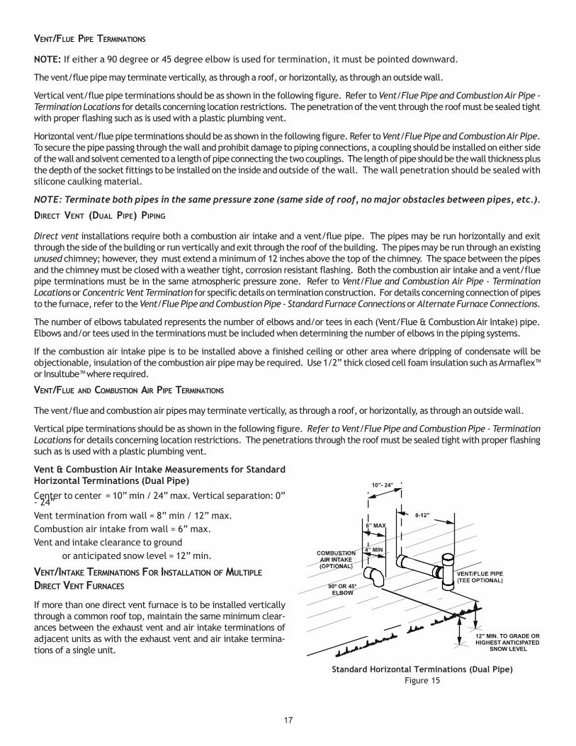
Vent & Combustion Air Intake Measurements for StandardHorizontal Terminations (Dual Pipe)
Center to center = 10” min / 24” max. Vertical separation: 0”- 24”Vent termination from wall = 8” min / 12” max.Combustion air intake from wall = 6” max.Vent and intake clearance to ground
or anticipated snow level = 12” min.
VENT/INTAKE TERMINATIONS FOR INSTALLATION OF MULTIPLE
DIRECT VENT FURNACES
If more than one direct vent furnace is to be installed verticallythrough a common roof top, maintain the same minimum clear-ances between the exhaust vent and air intake terminations ofadjacent units as with the exhaust vent and air intake termina-tions of a single unit.
Standard Horizontal Terminations (Dual Pipe)Figure 15
90º OR 45°ELBOW
12" MIN. TO GRADE ORHIGHEST ANTICIPATED
SNOW LEVEL
6” MAX
10”- 24”
4” MIN

18
If more than one direct vent furnace is to be installed horizontally through a common side wall, maintain the clearances as in thefollowing figure. Always terminate all exhaust vent outlets at the same elevation and always terminate all air intakes at the sameelevation.
CONCENTRIC VENT TERMINATION
Refer to the directions provided with the Concentric Vent Kit (CVENT) for installation specifications.
SIDE WALL VENT KIT
This kit is to be used with 2” or 3” direct vent systems. The vent kit must terminate outside the structure and may be installed withthe intake and exhaust pipes located side-by-side or with one pipe above the other. These kits are NOT intended for use with singlepipe (non-direct vent) installations.
Refer to the directions furnished with the Side Wall Vent Kit (p/n0170K00000S or 0170K00001S) for installation specifications.
CONDENSATE DRAIN LINES & DRAIN TRAP
A condensing gas furnace achieves its high level of efficiency byextracting heat from the products of combustion to the point wherecondensation takes place. The condensate must be collected inthe furnace drain trap and routed to an appropriate drain loca-tion in compliance with local and national codes.
Follow the bullets listed below when installing the drain system.Refer to the following sections for specific details concerning fur-nace drain trap installation and drain hose hook ups.
• The drain trap supplied with the furnace must be used.• The drain trap must be primed at time of installation.• The drain line between furnace and drain location must
meet local and national codes.• The drain line between furnace and drain location must
maintain a 1/4 inch per foot downward slope toward thedrain.
• Do not trap the drain line in any other location than at thedrain trap supplied with the furnace.
3” MIN
12” MIN TO GRADE OR HIGHEST ANTICIPATED SNOW LEVEL
12” MIN SEPARATION
3”MIN24”MAX
Termination of Multiple Direct Vent FurnacesFigure 18
Combustion Air Intake may also be snorkeled to obtain 12” min groundclearance.
Alternate Vent Termination Above Anticipated Snow Level(Dual Pipe)Figure 17
90°ELBOWS
12" MIN. ABOVEHIGHEST ANTICIPATED
SNOW LEVEL
3”-24” BETWEEN PIPES
Alternate Horizontal Vent Termination (Dual Pipe)Figure 16
90°ELBOWS
12" MIN. ABOVEHIGHEST ANTICIPATED
SNOW LEVEL
3” - 24”

19
Vertica l Installation
H orizontal Installation
Side Wall Vent KitFigure 19
• If the drain line is routed through an area which may seetemperatures near or below freezing, precautions must be takento prevent condensate from freezing within the drain line.
• If an air conditioning coil is installed with the furnace, a commondrain may be used. An open tee must be installed in the drainline, to relieve positive air pressure from the coil’s plenum. Thisis necessary to prohibit any interference with the function of thefurnace’s drain trap.
GENERAL DRAIN INFORMATION
All furnace models come with a factory installed drain trap. For ver-tical installations, the trap will remain in the factory position. Allfurnace models installed horizontally require the trap to be relocated.Many drain hoses have a built–in grommet which will provide a cabinet seal when installed. See instructions below for yourmodel and installation position. NOTE: Both sides of the drain trap must be primed prior to initial furnace start up
FIELD SUPPLIED DRAIN
Drain the furnace and air conditioning coil if applicable, in compliance with code requirements. In horizontal installations, afield installed rubber coupling will allow the drain trap to be removed for cleaning. The drain trap must be primed beforeinitial furnace start up. When an air conditioning coil drain is connected to the field supplied furnace drain, it must be ventedwith an open tee installed at a height no higher than the bottom of the furnace collector box to prevent air conditioning
condensate from backing up into the furnace if the common drainbecame blocked.
UPFLOW MODEL INSTALLED VERTICALLY
The trap and factory installed hoses remain as shipped. The fur-nace drain may exit either the right or left side of the furnacecabinet. Both sides of the cabinet have two .875” diameter holeswhich can be used interchangeably for drain and low voltage wir-ing purposes. If a higher drain exit is needed, a .875” diameterhole may be added in the area shown in Figure 21. Any unusedcabinet opening must be sealed. Do not allow drain hose to sag ortrap water.
Side Cut-Out12”
3” Right side shown.
Acceptablearea for
drain hole.
Figure 21
DRAIN EXITING RIGHT SIDE1. Locate and Install the 45º pipe / hose drain coupling from the
outside of the cabinet (barbed end goes in the cabinet) throughhole in the right side of the cabinet and secure with two fieldsupplied #8 self-tapping screws (see Figure 22).
#3
#1#2
#4#5
#6
#7#8
#9
#10
#11100 DegreeElbow
Coupling
Figure 20
NOTE: Hoses are model specificand not all hoses will be shipped with all models.

20
2. Locate the long drain hose #3 and cut at line “A” .3. Install large end of hose #3 to trap outlet and secure with 1.25"
clamp.4. Install smaller end of hose #3 on 45º elbow and secure with 1" clamp.5. Refer to Field Supplied Drain section for instructions on field supplied
/ installed drain on outlet of furnace trap.
DRAIN EXITING LEFT SIDE1. Install the 45 degree pipe / hose drain coupling from the outside of
the cabinet (barbed end goes in the cabinet) through the hole inthe left side of the cabinet and secure with two field supplied #8self-tapping screws (see Figure 22).
2. Locate the long drain hose #3 and cut at “B” line for a 17.5" cabinet;cut at line “C” for a 21" cabinet; do not cut for a “D” width cabinet.
3. Install large end of hose #3 to trap outlet and secure with 1.25"clamp.
4. Install smaller end of hose #3 on 45º elbow and secure with 1" clamp.5. Refer to Field Supplied Drain section for instructions on field supplied
/ installed drain on outlet of furnace trap.
UPFLOW MODEL INSTALLED HORIZONTALLY WITH RIGHT SIDE DOWN
(SEE FIGURE 23)Minimum 5 ½” clearance is required for the drain trap beneath thefurnace.1. Remove the clamps from both ends of the drain hoses.2. Remove the two screws holding the drain trap to the blowerdeck.3. Remove the trap and two hoses from the blower deck4. Remove the two plugs from the right side of the cabinet andinstall them in the blower deck.5. (Draining the Vent Elbow) Locate hose #2 (factory installed) andcut 1" away from the 45 degree bend, discard the 45degree section. Insert hose #2 from outside the cabinet throughthe cabinet drain hole nearest the top. Secure it to thebarbed fitting in the elbow with a red clamp.6. (Draining the Collector Box) Install the non-grommet end ofhose #11 from outside the cabinet in the bottom drainhole. Install on collector box and secure with a silver clamp.7. Use two silver clamps and secure the hoses to drain trap. The trap outlet faces the front of the furnace. Secure thetrap to the cabinet using two screws removed in step 2 by inserting the two screws through the large set of holes inthe top mounting tabs of the trap into the two predrilled holes in the side of the cabinet.8. Refer to Field Supplied Drain section for instructions on field supplied / installed drain on outlet of furnace trap.
UPFLOW MODEL INSTALLED HORIZONTALLY WITH LEFT SIDE DOWN (SEE FIGURE 24)Minimum 5 ½” clearance is required for the drain trap beneath the furnace.*Also see Front Cover Pressure Switch Tube Location onpage 101. Remove the clamps from the two drain tubes on the trap.2. Remove the two screws holding the drain trap to the blower deck.3. Remove the trap and hoses from the blower deck .4. Remove the two plugs from the left side of the cabinetand install them in the blower deck.5. (Draining the Vent Elbow) Locate hose #6. Measuring from the non-grommet end; cut off and discard 1 ½” fora “D” width cabinet, 5" for a “C” width cabinet, 8 ½” for a “B” width cabinet.6. Remove the rubber plug from vent – drain elbow side port. Place hose #6 on the vent – drain elbow side port andsecure with a silver clamp .
Hose #11 Hose #2
Figure 23
Installer selects right or left side drainand installs this hose accordingly.
Hose #1
Hose #2
45 degreebarb-pipeadapter
45 degreebarb-pipe
adapter
Figure 22
21
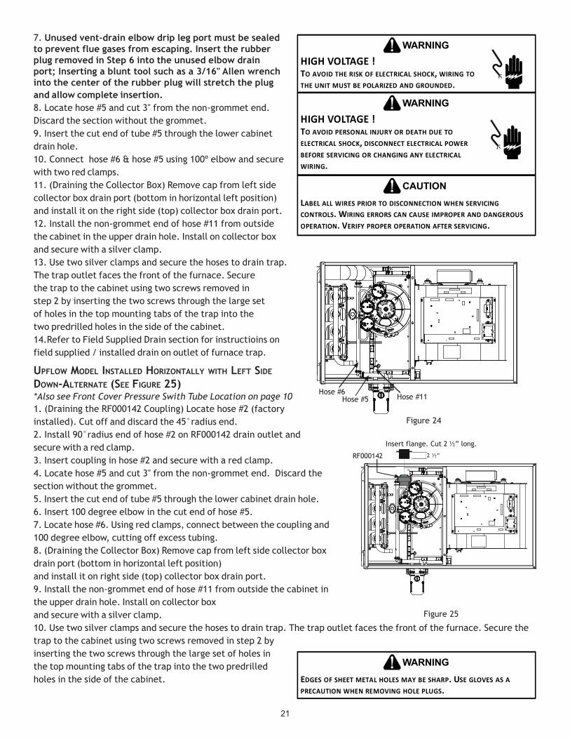
Hose #6Hose #5 Hose #11
Figure 24
7. Unused vent-drain elbow drip leg port must be sealedto prevent flue gases from escaping. Insert the rubberplug removed in Step 6 into the unused elbow drainport; Inserting a blunt tool such as a 3/16" Allen wrenchinto the center of the rubber plug will stretch the plugand allow complete insertion.8. Locate hose #5 and cut 3" from the non-grommet end.Discard the section without the grommet.9. Insert the cut end of tube #5 through the lower cabinetdrain hole.10. Connect hose #6 & hose #5 using 100º elbow and securewith two red clamps.11. (Draining the Collector Box) Remove cap from left sidecollector box drain port (bottom in horizontal left position)and install it on the right side (top) collector box drain port.12. Install the non-grommet end of hose #11 from outsidethe cabinet in the upper drain hole. Install on collector boxand secure with a silver clamp.13. Use two silver clamps and secure the hoses to drain trap.The trap outlet faces the front of the furnace. Securethe trap to the cabinet using two screws removed instep 2 by inserting the two screws through the large setof holes in the top mounting tabs of the trap into thetwo predrilled holes in the side of the cabinet.14.Refer to Field Supplied Drain section for instructioins onfield supplied / installed drain on outlet of furnace trap.
UPFLOW MODEL INSTALLED HORIZONTALLY WITH LEFT SIDE
DOWN-ALTERNATE (SEE FIGURE 25)*Also see Front Cover Pressure Swith Tube Location on page 101. (Draining the RF000142 Coupling) Locate hose #2 (factoryinstalled). Cut off and discard the 45°radius end.2. Install 90°radius end of hose #2 on RF000142 drain outlet andsecure with a red clamp.3. Insert coupling in hose #2 and secure with a red clamp.4. Locate hose #5 and cut 3" from the non-grommet end. Discard thesection without the grommet.5. Insert the cut end of tube #5 through the lower cabinet drain hole.6. Insert 100 degree elbow in the cut end of hose #5.7. Locate hose #6. Using red clamps, connect between the coupling and100 degree elbow, cutting off excess tubing.8. (Draining the Collector Box) Remove cap from left side collector boxdrain port (bottom in horizontal left position)and install it on right side (top) collector box drain port.9. Install the non-grommet end of hose #11 from outside the cabinet inthe upper drain hole. Install on collector boxand secure with a silver clamp.10. Use two silver clamps and secure the hoses to drain trap. The trap outlet faces the front of the furnace. Secure thetrap to the cabinet using two screws removed in step 2 byinserting the two screws through the large set of holes inthe top mounting tabs of the trap into the two predrilledholes in the side of the cabinet. EDGES OF SHEET METAL HOLES MAY BE SHARP. USE GLOVES AS A
PRECAUTION WHEN REMOVING HOLE PLUGS.
WARNING
HIGH VOLTAGE !TO AVOID THE RISK OF ELECTRICAL SHOCK, WIRING TO THE UNIT MUST BE POLARIZED AND GROUNDED.
WARNING
HIGH VOLTAGE !TO AVOID PERSONAL INJURY OR DEATH DUE TO ELECTRICAL SHOCK, DISCONNECT ELECTRICAL POWER BEFORE SERVICING OR CHANGING ANY ELECTRICAL WIRING.
WARNING
LABEL ALL WIRES PRIOR TO DISCONNECTION WHEN SERVICING CONTROLS. WIRING ERRORS CAN CAUSE IMPROPER AND DANGEROUS OPERATION. VERIFY PROPER OPERATION AFTER SERVICING.
CAUTION
Insert flange. Cut 2 ½” long.
R 000142F
Figure 25

22
ELECTRICAL CONNECTIONS
WIRING HARNESS
The wiring harness is an integral part of this furnace. Wires arecolor coded for identification purposes. Refer to the wiring dia-gram for wire routings. If any of the original wire as suppliedwith the furnace must be replaced, it must be replaced withwiring material having a temperature rating of at least 105° C.Any replacement wiring must be a copper conductor.
115 VOLT LINE CONNECTIONS
Before proceeding with electrical connections, ensure that thesupply voltage, frequency, and phase correspond to that speci-fied on the unit rating plate. Power supply to the furnace mustbe NEC Class 1, and must comply with all applicable codes. Thefurnace must be electrically grounded in accordance with localcodes or, in their absence, with the latest edition of The NationalElectric Code, ANSI NFPA 70 and/or The Canadian Electric CodeCSA C22.1.
Use a separate fused branch electrical circuit containing properlysized wire, and fuse or circuit breaker. The fuse or circuit breakermust be sized in accordance with the maximum overcurrent pro-tection specified on the unit rating plate. An electrical discon-nect must be provided at the furnace location.
Connect hot, neutral, and ground wires as shown in the wiringdiagram located on the unit’s blower door. For direct vent applications,the cabinet opening to the junction box must be sealed air tight usingeither an UL approved bushing such as Heyco Liquid Tight or by applyingnon-reactive UL approved sealant to bushing.
Line polarity must be observed when making field connections. Line volt-age connections can be made through either the right or left side panel.The furnace is shipped configured for a left side electrical connection withthe junction box located inside the burner compartment. To make electri-cal connections through the opposite side of the furnace, the junction boxmust be relocated to the other side of the burner compartment prior tomaking electrical connections. To relocate the junction box, follow thesteps shown below.
NOTE: Wire routing must not to interfere with circulator blower operation,filter removal, or routine maintenance.
JUNCTION BOX RELOCATION
Line voltage connections can be made through either the right or left side panel. The furnace is shipped configured for a leftside electrical connection. To make electrical connections through the opposite side of the furnace, the junction box must berelocated to the left side prior to making electrical connections. To relocate the junction box, perform the following steps.
1. Remove the burner compartment door.2. Remove and save the two screws securing the junction box to the side panel.3. Relocate junction box and associated plugs and grommets to opposite side panel. Secure with screws removed in step 2.
To ensure proper unit grounding, the ground wire should run from the furnace ground screw located inside the furnace junction boxall the way back to the electrical panel. NOTE: Do not use gas piping as an electrical ground. To confirm proper unit grounding,turn off the electrical power and perform the following check.
1. Measure resistance between the neutral (white) connection and one of the burners.2. Resistance should measure 10 ohms or less.
WARNING
TO AVOID THE RISK OF INJURY, ELECTRICAL SHOCK OR DEATH, THE FURNACE MUST BE ELECTRICALLY GROUNDED IN ACCORDANCE WITH LOCAL CODES OR, IN THEIR ABSENCE, WITH THE LATEST EDITION OF THE NATIONAL ELECTRICAL CODE.
WIRE ROUTING MUST NOT INTERFERE WITH CIRCULATOR BLOWER OPERATION, FILTER REMOVAL OR ROUTINE MAINTENANCE.
IMPORTANT NOTE
TO PREVENT PERSONAL INJURY OR DEATH DUE TO ELECTRIC SHOCK, DISCONNECT ELECTRICAL POWER BEFORE INSTALLING OR SERVICING THIS UNIT.
WARNING
HIGH VOLTAGE !TO AVOID THE RISK OF INJURY, ELECTRICAL SHOCK OR DEATH, THE FURNACE MUST BE ELECTRICALLY GROUNDED IN ACCORDANCE WITH LOCAL CODES OR IN THEIR ABSENCE, WITH THE LATEST EDITION OF THE NATIONAL ELECTRIC CODE.
WARNING
Insert flange. Cut 2 ½” long.
R 000142F
Figure 25
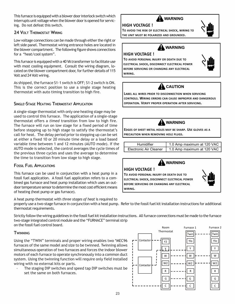
23
This furnace is equipped with a blower door interlock switch whichinterrupts unit voltage when the blower door is opened for servic-ing. Do not defeat this switch.
24 VOLT THERMOSTAT WIRING
Low voltage connections can be made through either the right orleft side panel. Thermostat wiring entrance holes are located inthe blower compartment. The following figure shows connectionsfor a “heat/cool system”.
This furnace is equipped with a 40 VA transformer to facilitate usewith most cooling equipment. Consult the wiring diagram, lo-cated on the blower compartment door, for further details of 115Volt and 24 Volt wiring.
As shipped, the furnace S1-1 switch is OFF; S1-2 switch is ON.This is the correct position to use a single stage heatingthermostat with auto timing transition to high fire.
SINGLE-STAGE HEATING THERMOSTAT APPLICATION
A single-stage thermostat with only one heating stage may beused to control this furnace. The application of a single-stagethermostat offers a timed transition from low to high fire.The furnace will run on low stage for a fixed period of timebefore stepping up to high stage to satisfy the thermostat’scall for heat. The delay period prior to stepping up can be setat either a fixed 10 or 20 minute time delay or a load basedvariable time between 1 and 12 minutes (AUTO mode). If theAUTO mode is selected, the control averages the cycle times ofthe previous three cycles and uses the average to determinethe time to transition from low stage to high stage.
FOSSIL FUEL APPLICATIONS
This furnace can be used in conjunction with a heat pump in afossil fuel application. A fossil fuel application refers to a com-bined gas furnace and heat pump installation which uses an out-door temperature sensor to determine the most cost efficient meansof heating (heat pump or gas furnace).
A heat pump thermostat with three stages of heat is required toproperly use a two-stage furnace in conjunction with a heat pump. Refer to the fossil fuel kit installation instructions for additionalthermostat requirements.
Strictly follow the wiring guidelines in the fossil fuel kit installation instructions. All furnace connections must be made to the furnacetwo-stage integrated control module and the “FURNACE” terminal stripon the fossil fuel control board.
TWINNING
Using the “TWIN” terminals and proper wiring enables two *MEC96furnaces of the same model and size to be twinned. Twinning allowssimultaneous operation of two furnaces and forces the indoor blowermotors of each furnace to operate synchronously into a common ductsystem. Using the twinning function will require only field installedwiring with no external kits or parts.
· The staging DIP switches and speed tap DIP switches must beset the same on both furnaces.
HIGH VOLTAGE !TO AVOID PERSONAL INJURY OR DEATH DUE TO ELECTRICAL SHOCK, DISCONNECT ELECTRICAL POWER BEFORE SERVICING OR CHANGING ANY ELECTRICAL WIRING.
WARNING
Humidifier 1.0 Amp maximum at 120 VACElectronic Air Cleaner 1.0 Amp maximum at 120 VAC
HIGH VOLTAGE !TO AVOID THE RISK OF ELECTRICAL SHOCK, WIRING TO THE UNIT MUST BE POLARIZED AND GROUNDED.
WARNING
HIGH VOLTAGE !TO AVOID PERSONAL INJURY OR DEATH DUE TO ELECTRICAL SHOCK, DISCONNECT ELECTRICAL POWER BEFORE SERVICING OR CHANGING ANY ELECTRICAL WIRING.
WARNING
LABEL ALL WIRES PRIOR TO DISCONNECTION WHEN SERVICING CONTROLS. WIRING ERRORS CAN CAUSE IMPROPER AND DANGEROUS OPERATION. VERIFY PROPER OPERATION AFTER SERVICING.
CAUTION
EDGES OF SHEET METAL HOLES MAY BE SHARP. USE GLOVES AS A PRECAUTION WHEN REMOVING HOLE PLUGS.
WARNING
RoomThermostat
Y2
Y
W
W2
R
G
C
Ylo
Y
W
W2
R
G
C
Ylo
Y
W
W2
R
G
C
Furnace 1 Furnace 2

24
115 VOLT LINE CONNECTION OF ACCESSORIES (HUMIDIFIER AND
ELECTRONIC AIR CLEANER)
The furnace integrated control module is equipped with line volt-age accessory terminals for controlling power to an optional field-supplied humidifier and/or electronic air cleaner.
The accessory load specifications are noted in the chart at right:
Turn OFF power to the furnace before installing any accessories. Follow the humidifier or air cleaner manufacturers’ instructions forlocating, mounting, grounding, and controlling these accessories. Accessory wiring connections are to be made through the 1/4"quick connect terminals provided on the furnace integrated control module. The humidifier and electronic air cleaner hot terminalsare identified as HUM and EAC. The humidifier and electronic air cleaner neutral terminals are identified as NEUTRAL. All field wiringmust conform to applicable codes. Connections should be made as shown.
If it is necessary for the installer to supply additional line voltage wiring to the inside of the furnace, the wiring must conform to alllocal codes, and have a minimum temperature rating of 105°C. All line voltage wire splices must be made inside the furnace junctionbox.
The integrated control module humidifier terminal (HUM) is ener-gized with 115 volts whenever the induced draft blower is ener-gized. The integrated control module electronic air cleaner terminal(EAC) is energized with 115 volts whenever the circulator blower isenergized. This terminal can also be used to provide 115 voltpower to a humidifier transformer. The remaining primary trans-former wire would be connected to the Line N on the controlboard.
GAS SUPPLY AND PIPING
The furnace rating plate includes the approved furnace gas inputrating and gas types. The furnace must be equipped to operate on the type of gas applied. This includes any conversion kits requiredfor alternate fuels and/or high altitude.
Inlet gas supply pressures must be maintained within the ranges specified in the adjacent table. The supply pressure must beconstant and available with all other household gas fired appliances operating. The minimum gas supply pressure must be maintainedto prevent unreliable ignition. The maximum must not be exceeded to prevent unit overfiring.
CAUTION
TO PREVENT UNRELIABLE OPERATION OR EQUIPMENT DAMAGE, THE INLET GAS SUPPLY PRESSURE MUST BE AS SPECIFIED ON THE UNIT RATING PLATE WITH ALL OTHER HOUSEHOLD GAS FIRED APPLIANCES OPERATING.
Thermostat - Single -Stage Heatingwith Single-Stage Cooling
NOTE: To apply a single-stage HeatingThermostat, the thermostat selectorswitch on the Integrated Control Modulemust be set on single-stage.
Figure 26
Thermostat - Two-Stage Heating withTwo-Stage Cooling
Thermostat Wiring Diagrams
Figure 28
Thermostat - Two-Stage Heatingwith Single-Stage Cooling
Figure 27
R
Y C
Furnace Integrated
Control Module
Remote Condensing Unit(Single-Stage Cooling)
R
R
Y C
Furnace Integrated
Control Module
Remote Condensing Unit(Single-Stage Cooling)
R
W1 W2Y Furnace Integrated
Control Module
Remote Condensing Unit(Two-Stage Cooling)
Y2
W1 W2Y2
DIP Switch Group
DIP Switch
NumberPurpos e
Auto 1 OFF* 2 ON*10 Minutes 1 ON 2 OFF20 Minutes 1 ON 2 ON
2 Stage 1 OFF 2 OFF90 Seconds 3 OFF 4 OFF
120 Seconds 3 OFF 4 ON150 Seconds 3 ON* 4 OFF*180 Seconds 3 ON* 4 ON
* = Factory Pos i tion
Function
S1
1, 2
3, 4
Heat Staging /
Dela y
Blower Hea t Off
Delay

25
HIGH ALTITUDE DERATE
When this furnace is installed at high altitude, the appropriate High Altitude orifice kit must be applied. This is required due to thenatural reduction in the density of both the gas fuel and combustion air as altitude increases. The kit will provide the proper designcertified input rate within the specified altitude range.
High altitude kits are purchased according to the installation altitude and usage of either natural or propane gas. Consult the furnaceSpecification Sheet for appropriate kits.
Do not derate the furnace by adjusting the manifold pressure to a lower pressure than specified on the furnace rating plate. Thecombination of the lower air density and a lower manifold pressure will prohibit the burner orifice from drawing the proper amount ofair into the burner. This may cause incomplete combustion, flashback, and possible yellow tipping.
In some areas the gas supplier may artificially derate the gas in an effort to compensate for the effects of altitude. If the gas isartificially derated, the appropriate orifice size must be determined based upon the BTU/ft3 content of the derated gas and thealtitude. Refer to the National Fuel Gas Code, NFPA 54/ANSI Z223.1, and information provided by the gas supplier to determine theproper orifice size.
A different pressure switch may be required at high altitude re-gardless of the BTU/ft3 content of the fuel used. Consult thefurnace Specification Sheet for pressure switch.
PROPANE GAS CONVERSION
This unit is configured for natural gas, but may be converted foruse with L.P. gas. Refer to the section on PROPANE GAS/HIGHALTITUDE INSTALLATIONS for L.P. kit selection.
Consult the furnace Specification Sheet for a listing of appro-priate kits. The indicated kits must be used to insure safe andproper furnace operation. All conversions must be performed by aqualified installer, or service agency.
GAS VALVE
This unit is equipped with a 24 volt gas valve controlled during furnace operation by theintegrated control module. As shipped, the valve is configured for natural gas. The valveis field convertible for use with propane gas by replacing the regulator spring with a propanegas spring from an appropriate manufacturer’s propane gas conversion kit. Taps for mea-suring the gas supply pressure and manifold pressure are provided on the valve.
The gas valve has a manual ON/OFF control located on the valve itself. This control may beset only to the “ON” or “OFF” position. Refer to the lighting instructions label or StartupProcedure & Adjustment for use of this control during start up and shut down periods.
GAS PIPING CONNECTIONS
The gas piping supplying the furnace must be properly sized based on the gas flow required,specific gravity of the gas, and length of the run. The gas line installation must comply withlocal codes, or in their absence, with the latest edition of the National Fuel Gas Code, NFPA54/ANSI Z223.1.
To connect the furnace to the building’s gas piping, the installermust supply a ground joint union, drip leg, manual shutoff valve,and line and fittings to connect to gas valve. In some cases, theinstaller may also need to supply a transition piece from 1/2" pipeto a larger pipe size.
The following stipulations apply when connecting gas piping. Referto Gas Piping Connections figure for typical gas line connections tothe furnace.
• Gas piping must be supported external to the furnace cabinetso that the weight of the gas line does not distort the burnerrack, manifold or gas valve.
Accessories - Accessories WiringFigure 29
TO AVOID POSSIBLE UNSATISFACTORY OPERATION OF EQUIPMENT DAMAGE DUE TO UNDERFIRING OR EQUIPMENT, USE THE PROPER SIZE OF NATURAL/PROPANE GAS PIPING NEEDED WHEN RUNNING PIPE FROM THE METER/TANK TO THE FURNACE.
WARNING
Natural Gas Minimum: 4.5" w.c. Maximum: 10.0" w.c.Propane Gas Minimum: 11.0" w.c. Maximum: 13.0" w.c.
INLET GAS SUPPLY PRESSURE
HIGH VOLTAGE !TO AVOID PERSONAL INJURY OR DEATH DUE TO ELECTRICAL SHOCK, DISCONNECT ELECTRICAL POWER BEFORE SERVICING OR CHANGING ANY ELECTRICAL WIRING.
WARNING
Humidifier 1.0 Amp maximum at 120 VACElectronic Air Cleaner 1.0 Amp maximum at 120 VAC

26
• Use black iron or steel pipe and fittings for building piping.Where possible, use new pipe that is properly chamfered,reamed, and free of burrs and chips. If old pipe is used, besure it is clean and free of rust, scale, burrs, chips, and oldpipe joint compound.
• Use pipe joint compound on male threads ONLY. Always usepipe joint compound (pipe dope) that is APPROVED FOR ALLGASSES. DO NOT apply compound to the first two threads.
• Use ground joint unions.
• Install a drip leg to trap dirt and moisture before it can enter the gas valve. The drip leg must be a minimum of three incheslong.
• Install a 1/8" NPT pipe plug fitting, accessible for test gage connection, immediately upstream of the gas supply connection tothe furnace.
• Always use a back-up wrench when making the connection to the gas valve to keep it from turning. The orientation of the gasvalve on the manifold must be maintained as shipped from the factory. Maximum torque for the gas valve connection is 375in-lbs; excessive over-tightening may damage the gas valve.
• Install a manual shutoff valve between the gas meter and unit within six feet of the unit. If a union is installed, the union mustbe downstream of the manual shutoff valve, between the shutoff valve and the furnace.
• Tighten all joints securely.
• Connect the furnace to the building piping by one of the following methods:
– Rigid metallic pipe and fittings.
– Semi-rigid metallic tubing and metallic fittings. Aluminum alloy tubing must not be used in exterior locations. In order toseal the grommet cabinet penetration, rigid pipe must be used to reach the outside of the cabinet. A semi-rigid connectorto the gas piping may be used from there.
• Use listed gas appliance connectors in accordance with their instructions. Connectors must be fully in the same room as thefurnace.
• Protect connectors and semirigid tubing against physical and thermal damage when installed. Ensure aluminum-alloy tubingand connectors are coated to protect against external corrosion when in contact with masonry, plaster, or insulation, orsubjected to repeated wetting by liquids such as water (except rain water), detergents, or sewage.
The gas piping may enter the left or right side of the furnacecabinet. The installer must supply rigid pipe long enough to reachthe outside of the cabinet to seal the grommet cabinet penetration.A semi-rigid connector to the gas piping can be used outside thecabinet per local codes. 1/2” NPT pipe and fittings are required.For models with an “L” shaped manifold, a 4 1/2” long nipple isrequired. For models with a hook shaped manifold, a 2” longnipple is required.
A semi-rigid connector to the gas piping can be used outsidethe cabinet per local codes. From the elbow, the length of pipeand the fittings required will vary by the side chosen, locationof union and cabinet width. The union may be placed inside oroutside of the cabinet.
GAS PIPING CHECKS
Before placing unit in operation, leak test the unit and gas connec-tions.
Check for leaks using an approved chloride-free soap and water solution, an electronic combustible gas detector, or other approvedtesting methods.
NOTE: Never exceed specified pressures for testing. Higher pressure may damage the gas valve and cause subsequent overfiring,resulting in heat exchanger failure.
WARNING
POSSIBLE PROPERTY DAMAGE, PERSONAL INJURY OR DEATH MAY OCCUR IF THE CORRECT CONVERSION KITS ARE NOT INSTALLED. THE APPROPRIATE KITS MUST BE APPLIED TO ENSURE SAFE AND PROPER FURNACE OPERATION. ALL CONVERSIONS MUST BE PERFORMED BY A QUALIFIED INSTALLER OR SERVICE AGENCY.
Natural Gas Capacity of PipeIn Cubic Feet of Gas Per Hour (CFH)
Length of Nominal Black Pipe SizePipe in Feet 1/2" 3/4" 1" 1 1/4" 1 1/2"
10 132 278 520 1050 160020 92 190 350 730 110030 73 152 285 590 98040 63 130 245 500 76050 56 115 215 440 67060 50 105 195 400 61070 46 96 180 370 56080 43 90 170 350 53090 40 84 160 320 490100 38 79 150 305 460
(Pressure 0.5 psig or less and pressure drop of 0.3" W.C.; Based on0.60 Specif ic Gravity Gas)
CFH = BTUH Furnace Input Heating Value of Gas (BTU/Cubic Foot)
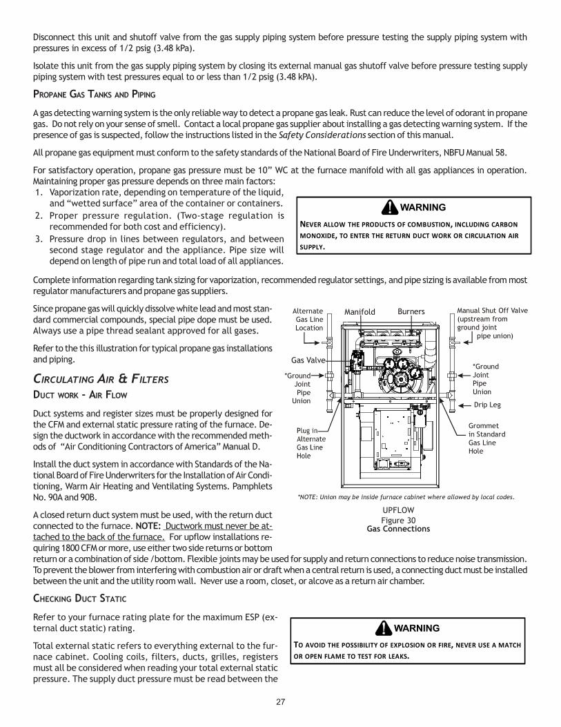
27
Disconnect this unit and shutoff valve from the gas supply piping system before pressure testing the supply piping system withpressures in excess of 1/2 psig (3.48 kPa).
Isolate this unit from the gas supply piping system by closing its external manual gas shutoff valve before pressure testing supplypiping system with test pressures equal to or less than 1/2 psig (3.48 kPA).
PROPANE GAS TANKS AND PIPING
A gas detecting warning system is the only reliable way to detect a propane gas leak. Rust can reduce the level of odorant in propanegas. Do not rely on your sense of smell. Contact a local propane gas supplier about installing a gas detecting warning system. If thepresence of gas is suspected, follow the instructions listed in the Safety Considerations section of this manual.
All propane gas equipment must conform to the safety standards of the National Board of Fire Underwriters, NBFU Manual 58.
For satisfactory operation, propane gas pressure must be 10” WC at the furnace manifold with all gas appliances in operation.Maintaining proper gas pressure depends on three main factors:1. Vaporization rate, depending on temperature of the liquid,
and “wetted surface” area of the container or containers.2. Proper pressure regulation. (Two-stage regulation is
recommended for both cost and efficiency).3. Pressure drop in lines between regulators, and between
second stage regulator and the appliance. Pipe size willdepend on length of pipe run and total load of all appliances.
Complete information regarding tank sizing for vaporization, recommended regulator settings, and pipe sizing is available from mostregulator manufacturers and propane gas suppliers.
Since propane gas will quickly dissolve white lead and most stan-dard commercial compounds, special pipe dope must be used.Always use a pipe thread sealant approved for all gases.
Refer to the this illustration for typical propane gas installationsand piping.
CIRCULATING AIR & FILTERS
DUCT WORK - AIR FLOW
Duct systems and register sizes must be properly designed forthe CFM and external static pressure rating of the furnace. De-sign the ductwork in accordance with the recommended meth-ods of “Air Conditioning Contractors of America” Manual D.
Install the duct system in accordance with Standards of the Na-tional Board of Fire Underwriters for the Installation of Air Condi-tioning, Warm Air Heating and Ventilating Systems. PamphletsNo. 90A and 90B.
A closed return duct system must be used, with the return ductconnected to the furnace. NOTE: Ductwork must never be at-tached to the back of the furnace. For upflow installations re-quiring 1800 CFM or more, use either two side returns or bottomreturn or a combination of side /bottom. Flexible joints may be used for supply and return connections to reduce noise transmission.To prevent the blower from interfering with combustion air or draft when a central return is used, a connecting duct must be installedbetween the unit and the utility room wall. Never use a room, closet, or alcove as a return air chamber.
CHECKING DUCT STATIC
Refer to your furnace rating plate for the maximum ESP (ex-ternal duct static) rating.
Total external static refers to everything external to the fur-nace cabinet. Cooling coils, filters, ducts, grilles, registersmust all be considered when reading your total external staticpressure. The supply duct pressure must be read between the
TO AVOID THE POSSIBILITY OF EXPLOSION OR FIRE, NEVER USE A MATCH OR OPEN FLAME TO TEST FOR LEAKS.
WARNING
NEVER ALLOW THE PRODUCTS OF COMBUSTION, INCLUDING CARBON MONOXIDE, TO ENTER THE RETURN DUCT WORK OR CIRCULATION AIR SUPPLY.
WARNING
AlternateGas LineLocation
Gas Valve
Burners Manual Shut Off Valve(upstream fromground joint pipe union)
Drip Leg
Grommetin StandardGas LineHole
*GroundJointPipeUnion
*GroundJointPipe
Union
*NOTE: Union may be inside furnace cabinet where allowed by local codes.
Manifold
UPFLOWFigure 30
Gas Connections

28
furnace and the cooling coil. This reading is usually taken by removing the “A” shaped block off plate from the end on thecoil; drilling a test hole in it and reinstalling the block off plate. Take a duct static reading at the test hole. Tape up the testhole after your test is complete. The negative pressure must be read between the filter and the furnace blower.
Too much external static pressure will result in insufficient airthat can cause excessive temperature rise. This can cause limitswitch tripping and heat exchanger failure.
To determine total external duct static pressure, proceed asfollows;
1. With clean filters in the furnace, use a draft gauge (in-clined manometer) to measure the static pressure of thereturn duct at the inlet of the furnace. (Negative Pressure)
2. Measure the static pressure of the supply duct. (PositivePressure)
3. The difference between the two numbers is .4” w.c.
Example:static reading from return duct = -.1" w.c.static reading from supply duct = .3" w.c.total external static pressure on this system = .4" w.c.
NOTE: Both readings may be taken simultaneously and read directlyon the manometer if so desired. If an air conditioner coil or Elec-tronic Air Cleaner is used in conjunction with the furnace, the read-ings must also include theses components, as shown in the followingdrawing.
4. Consult proper tables for the quantity of air.
If the total external static pressure exceeds the maximum listed onthe furnace rating plate, check for closed dampers, registers, undersized and/or oversized poorly laid out duct work.
The temperature rise of the furnace must be within the temperature rise range listed on the furnace rating plate.
BOTTOM RETURN AIR OPENING [UPFLOW MODELS]The bottom return air opening on upflow models utilizes a “lance and cut” methodto remove sheet metal from the duct opening in the base pan. To remove, simplypress out the lanced sections by hand to expose the metal strips retaining thesheet metal over the duct opening. Using tin snips, cut the metal strips andremove the sheet metal covering the duct opening. In the corners of the open-ing, cut the sheet metal along the scribe lines to free the duct flanges. Using thescribe line along the duct flange as a guide, unfold the duct flanges around theperimeter of the opening using a pair of seamer pliers or seamer tongs.
NOTE: Airflow area will be reduced by approximately 18% if duct flanges are notunfolded. This could cause performance issues and noise issues.
When the furnace is used in connection with a cooling unit, the furnace should beinstalled in parallel with or on the upstream side of the cooling unit to avoidcondensation in the heating element. With a parallel flow arrangement, thedampers or other means used to control the flow of air must be adequate toprevent chilled air from entering the furnace and, if manually operated, must beequipped with means to prevent operation of either unit unless the damper is inthe full heat or cool position.
When the furnace is installed without a cooling coil, it is recommended that aremovable access panel be provided in the outlet air duct. This opening shall beaccessible when the furnace is installed and shall be of such a size that the heatexchanger can be viewed for visual light inspection or such that a sampling probecan be inserted into the airstream. The access panel must be made to prevent air leaks when the furnace is in operation.
Checking Static Pressure(80% Furnace Shown, 90% Similar)
Figure 32
IF THE GAS FURNACE IS INSTALLED IN A BASEMENT, AN EXCAVATED AREA OR CONFINED SPACE, IT IS STRONGLY RECOMMENDED TO CONTACT A PROPANE SUPPLIER TO INSTALL A GAS DETECTING WARNING DEVICE IN CASE OF A GAS LEAK.
SINCE PROPANE GAS IS HEAVIER THAN AIR, ANY LEAKING GAS CAN SETTLE IN ANY LOW AREAS OR CONFINED SPACES.
PROPANE GAS ODORANT MAY FADE, MAKING THE GAS UNDETECTABLE EXCEPT WITH A WARNING DEVICE.
•
•
WARNING
200 PSIGMaximum
5 to 15 PSIG(20 PSIG Max.)
Continuous11" W.C.
Second StageRegulator
First StageRegulator
Propane Gas Installation (Typ.)Figure 31
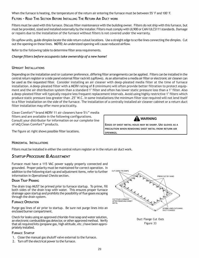
29
When the furnace is heating, the temperature of the return air entering the furnace must be between 55°F and 100°F.
FILTERS - READ THIS SECTION BEFORE INSTALLING THE RETURN AIR DUCT WORK
Filters must be used with this furnace. Discuss filter maintenance with the building owner. Filters do not ship with this furnace, butmust be provided, sized and installed externally by the installer. Filters must comply with UL900 or CAN/ULCS111 standards. Damageor repairs due to the installation of the furnace without filters is not covered under the warranty.
On upflow units, guide dimples locate the side return cutout locations. Use a straight edge to scribe lines connecting the dimples. Cutout the opening on these lines. NOTE: An undersized opening will cause reduced airflow.
Refer to the following table to determine filter area requirements.
Change filters before occupants take ownership of a new home!
UPRIGHT INSTALLATIONS
Depending on the installation and/or customer preference, differing filter arrangements can be applied. Filters can be installed in thecentral return register or a side panel external filter rack kit (upflows). As an alternative a media air filter or electronic air cleaner canbe used as the requested filter. Consider installing an air cleaner with deep-pleated media filter at the time of furnaceinstallation. A deep-pleated filter with a MERV rating of 8 (minimum) will often provide better filtration to protect equip-ment and the air distribution system than a standard 1" filter and often has lower static pressure loss than a 1" filter. Alsoa deep-pleated filter will typically require less frequent replacement intervals. Avoid using highly restrictive 1" filters whichproduce static pressure loss greater than .25" W.C. In some installations the minimum filter size required will not lend itselfto a filter installation on the side of the furnace. The installation of a centrally installed air cleaner cabinet or a return ductfilter installation may offer more practicality.
Clean Comfort™ brand MERV 11 air cleaners have 5¼” mediafilters and are available in the following configurations.Consult your distributor for information on our complete lineof IAQ Clean Comfort™ products.
The figure at right shows possible filter locations.
HORIZONTAL INSTALLATIONS
Filters must be installed in either the central return register or in the return air duct work.
STARTUP PROCEDURE & ADJUSTMENT
Furnace must have a 115 VAC power supply properly connected andgrounded. Proper polarity must be maintained for correct operation. Inaddition to the following start-up and adjustment items, refer to furtherinformation in Operational Checks section.
DRAIN TRAP PRIMING
The drain trap MUST be primed prior to furnace startup. To prime, fillboth sides of the drain trap with water. This ensures proper furnacedrainage upon startup and prohibits the possibility of flue gases escapingthrough the drain system.
FURNACE OPERATION
Purge gas lines of air prior to startup. Be sure not purge lines into anenclosed burner compartment.
Check for leaks using an approved chloride-free soap and water solution,an electronic combustible gas detector, or other approved method. Verifythat all required kits (propane gas, high altitude, etc.) have been appro-priately installed.
FURNACE STARTUP
1. Close the manual gas shutoff valve external to the furnace.2. Turn off the electrical power to the furnace.
EDGES OF SHEET METAL HOLES MAY BE SHARP. USE GLOVES AS A PRECAUTION WHEN REMOVING SHEET METAL FROM RETURN AIR OPENINGS.
WARNING
CUT FOUR CORNERSAFTER REMOVING SHEETMETAL
CUT USING TIN SNIPS
PRESS OUT BY HAND
SCRIBE LINES OUTLININGDUCT FLANGES
Duct Flange Cut OutsFigure 33

30
3. Set the room thermostat to the lowest possible setting.4. Remove the burner compartment door.
NOTE: This furnace is equipped with an ignition device whichautomatically lights the burner. Do not try to light the burner byhand.
5. Move the furnace gas valve manual control to the OFF position.6. Wait five minutes then smell for gas. Be sure check near the
floor as some types of gas are heavier than air.7. If you smell gas after five minutes, immediately follow the Safety Considerations on page 2 of this manual. If you do not smell
gas after five minutes, move the furnace gas valve manual control to the ON position.8. Replace the burner compartment door.9. Open the manual gas shutoff valve external to the furnace.10. Turn on the electrical power to the furnace.11. Adjust the thermostat to a setting above room temperature.12. After the burners are lit, set the thermostat to desired temperature.
FURNACE SHUTDOWN
1. Set the thermostat to the lowest setting.The integrated control will close the gas valve and extinguish flame. Following a 15 second delay, the induced draft blower willbe de-energized. The circulator blower will shut off after the time delay expires (selectable 90, 120, 150, 180 seconds).
2. Remove the burner compartment door and move the furnace gas valve manual control to the OFF position.3. Close the manual gas shutoff valve external to the furnace.4. Replace the burner compartment door.
GAS SUPPLY PRESSURE MEASUREMENT
GAS PRESSURE TEST
The line pressure supplied to the gas valve must be within therange specified below. The supply pressure can be measured atthe gas valve inlet pressure tap or at a hose fitting installed in thegas piping drip leg. The supply pressure must be measured withthe burners operating. To measure the gas supply pressure, usethe following procedure.
1. Turn OFF gas to furnace at the manual gas shutoff valveexternal to the furnace.
2. Connect a calibrated water manometer (or appropriate gaspressure gauge) at either the gas valve inlet pressure tap orthe gas piping drip leg. See White-Rodgers 36J54 gas valvefigure for location of inlet pressure tap.
CAUTION
TO PREVENT UNRELIABLE OPERATION OR EQUIPMENT DAMAGE, THE INLET GAS SUPPLY PRESSURE MUST BE AS SPECIFIED ON THE UNIT RATING PLATE WITH ALL OTHER HOUSEHOLD GAS FIRED APPLIANCES OPERATING.
Air Cleaner Installation Location
Maximum Heating Airflow
Filter (Media) Dimensions
Part Number Air Cleaner Family
Side or bottom return 1200 CFM 16 in X 20 in x 5¼" AM11-1620-5
Side or bottom return 1600 CFM 16 in X 25 in x 5¼" AM11-1625-5
Side or bottom return 1600 CFM 20 in X 20 in x 5¼" AM11-2020-5
Side or bottom return 2000 CFM 20 in X 25 in x 5¼" AM11-2025-5
Side return
(for 2 separate returns)
Side return (Right angle) 2000 CFM 20 in X 25 in x 5¼" AM11-2025-5RA AM11-5RA
Bottom return (platform) 2000 CFM 20 in X 25 in x 5¼" AM11-2832-5PP
Bottom return (platform) 2000 CFM 20 in X 25 in x 5¼" AM11-2843-5PPAM11-5PP
AM11-5
2 X 1600 CFM 2, 16 in X 25 in x 5¼" AM11-3225-5 AM11-3225
Model Minimum Recommended Filter Size^*MEC960302BN* 1 - 16 X 25 Side or Bottom*MEC960402BN* 1 - 16 X 25 Side or Bottom*MEC960603BN* 1 - 16 X 25 Side or Bottom*MEC960803BN* 1 - 16 X 25 Side or Bottom*MEC960804CN* 1 - 16 X 25 Side or Bottom*MEC961004CN* 1 - 16 X 25 Side or Bottom*MEC961005CN* 1 - 20 X 25 Bottom / 2 - 16 X 25 Side Return*MEC961205DN* 1 - 20 X 25 Bottom / 2 - 16 X 25 Side Return
^ Larger filters may be used, filters may also be centrally located
Filter Sizing Chart
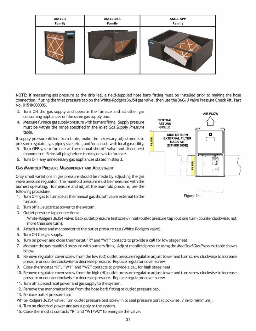
31
NOTE: If measuring gas pressure at the drip leg, a field-supplied hose barb fitting must be installed prior to making the hoseconnection. If using the inlet pressure tap on the White-Rodgers 36J54 gas valve, then use the 36G/J Valve Pressure Check Kit, PartNo. 0151K00000S.
3. Turn ON the gas supply and operate the furnace and all other gasconsuming appliances on the same gas supply line.
4. Measure furnace gas supply pressure with burners firing. Supply pressuremust be within the range specified in the Inlet Gas Supply Pressuretable.
If supply pressure differs from table, make the necessary adjustments topressure regulator, gas piping size, etc., and/or consult with local gas utility.5. Turn OFF gas to furnace at the manual shutoff valve and disconnect
manometer. Reinstall plug before turning on gas to furnace.6. Turn OFF any unnecessary gas appliances stated in step 3.
GAS MANIFOLD PRESSURE MEASUREMENT AND ADJUSTMENT
Only small variations in gas pressure should be made by adjusting the gasvalve pressure regulator. The manifold pressure must be measured with theburners operating. To measure and adjust the manifold pressure, use thefollowing procedure.1. Turn OFF gas to furnace at the manual gas shutoff valve external to the
furnace.2. Turn off all electrical power to the system.3. Outlet pressure tap connections:
White-Rodgers 36J54 valve: Back outlet pressure test screw (inlet/outlet pressure tap) out one turn (counterclockwise, notmore than one turn).
4. Attach a hose and manometer to the outlet pressure tap (White-Rodgers valve).5. Turn ON the gas supply.6. Turn on power and close thermostat “R” and “W1” contacts to provide a call for low stage heat.7. Measure the gas manifold pressure with burners firing. Adjust manifold pressure using the Manifold Gas Pressure table shown
below.8. Remove regulator cover screw from the low (LO) outlet pressure regulator adjust tower and turn screw clockwise to increase
pressure or counterclockwise to decrease pressure. Replace regulator cover screw.9. Close thermostat “R”, “W1” and “W2” contacts to provide a call for high stage heat.10. Remove regulator cover screw from the high (HI) outlet pressure regulator adjust tower and turn screw clockwise to increase
pressure or counterclockwise to decrease pressure. Replace regulator cover screw.11. Turn off all electrical power and gas supply to the system.12. Remove the manometer hose from the hose barb fitting or outlet pressure tap.13. Replace outlet pressure tap:White-Rodgers 36J54 valve: Turn outlet pressure test screw in to seal pressure port (clockwise, 7 in-lb minimum).14. Turn on electrical power and gas supply to the system.15. Close thermostat contacts “R” and “W1/W2” to energize the valve.
FIL
TE
R
AIR FLOW
CENTRALRETURNGRILLE
FIL
TE
R
SIDE RETURNEXTERNAL FILTER
RACK KIT(EITHER SIDE)
Figure 34
AM11-5Fam ily
AM11-5RAFam ily
AM11-5PPFam ily

32
Using a leak detection solution or soap suds, check for leaks at outlet pressure tap plug (Honeywell valve) or screw (White-Rodgersvalve). Bubbles forming indicate a leak. SHUT OFF GAS AND REPAIR ALL LEAKS IMMEDIATELY!NOTE: For gas to gas conversion, consult your dealer for appropriate conversion.
GAS INPUT RATE MEASUREMENT (NATURAL GAS ONLY)
The actual gas input rate to the furnace must never be greater than that specified on the unit rating plate. To measure natural gasinput using the gas meter, use the following procedure.1. Turn OFF the gas supply to all other gas-burning appliances except the furnace.
2. While the furnace is operating at high fire rate, time and record one complete revolution of the gas meter dial measuring thesmallest quantity, usually the dial that indicates 1/2 cu. ft. per revolution. You will use this number to calculate thequantity of gas in cubic ft. if the furnace would consume if it ran steadily for one hour (3600 seconds).
3. If the 1/2 cu. ft. dial was used, multiply your number x 2.
EXAMPLE: If it took 23 seconds to complete one revolution of the 1/2 ft. dial (23 x 2 = 46).
This tells us that at this rate, it would take 46 seconds to consume one cu. ft. of gas. 3600 / 46 = 78.
This tells us that in one hour, the furnace would consume 78 cu. ft. of gas.
The typical value range for 1 cu. ft. of natural gas is around 1000 BTU. Check with your gas utility, if possible. In thisexample, the furnace is consuming 78,000 BTUH.
NOTE: The final manifold pressure cannot vary by more than ± 0.3” w.c. for Natural and + 0.5” for LP from the specifiedsetting. Consult your local gas supplier if additional input rate adjustment is required.
4. Turn ON gas to and relight all other appliances turned off in step1. Be certain that all appliances are functioning properly andthat all pilot burners are operating.
TEMPERATURE RISE
Temperature rise must be within the range specified on the unitrating plate. An incorrect temperature rise may result in condensing in or overheating of the heat exchanger. An airflow andtemperature rise table is provided in the Specification Sheet applicable to your model. Determine and adjust temperature rise asfollows:1. Operate furnace with burners firing for approximately ten minutes. Ensure all registers are open and all duct dampers are in
their final (fully or partially open) position.2. Place thermometers in the return and supply ducts as close to the furnace as possible. Thermometers must not be influenced
by radiant heat by being able to “see” the heat exchanger.3. Subtract the return air temperature from the supply air temperature to determine the air temperature rise. Allow adequate
time for thermometer readings to stabilize.
Natural Gas Minimum: 4.5" w.c. Maximum: 10.0" w.c.Propane Gas Minimum: 11.0" w.c. Maximum: 13.0" w.c.
INLET GAS SUPPLY PRESSURE
White-Rodgers Model 36J54 (Two-Stage)
White-Rodgers Model 36J54 Connected to ManometerFigure 34B
INLET OUTLET
Gas Valve On/OffSelector Switch
InletPressureBoss
Low FireRegulatorAdjust
Manometer
ManometerHose
High Fire RegulatorAdjust
RegulatorVent
OutletPressure Boss
Open toAtmosphere
On/Off Switch
High Fire CoilTerminal (HI) Coaxial Coil
Terminal (M)CommonTerminal(C)
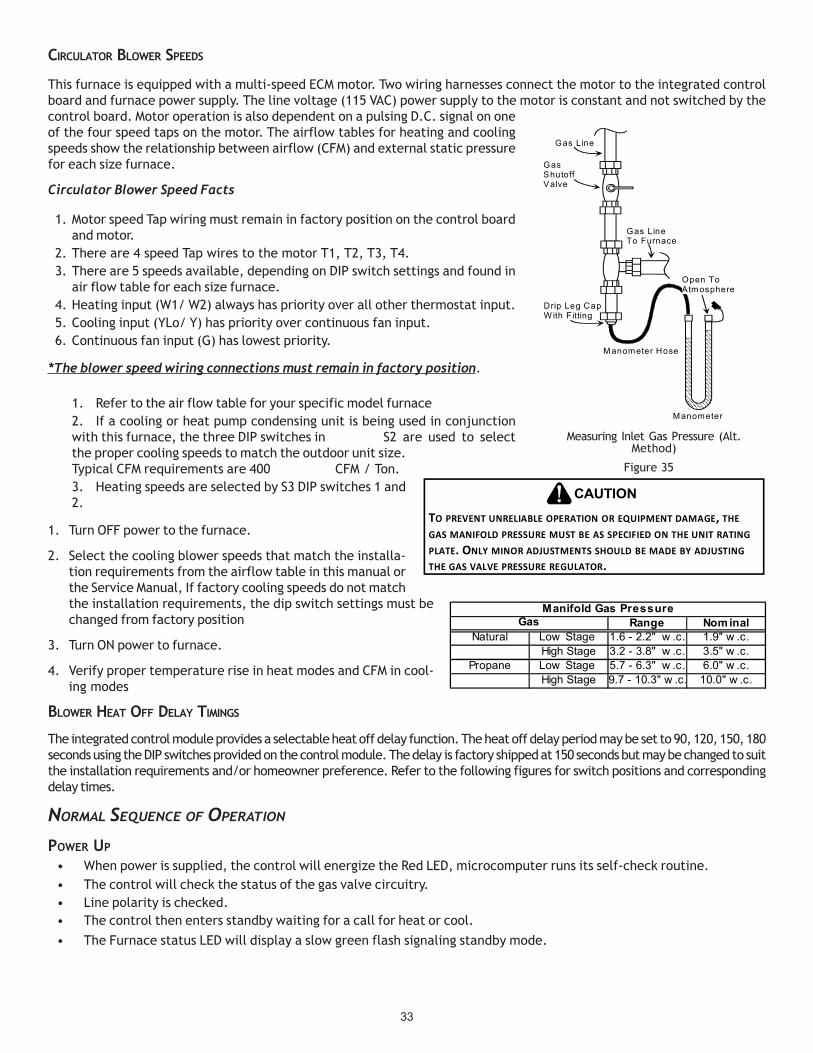
33
CIRCULATOR BLOWER SPEEDS
This furnace is equipped with a multi-speed ECM motor. Two wiring harnesses connect the motor to the integrated controlboard and furnace power supply. The line voltage (115 VAC) power supply to the motor is constant and not switched by thecontrol board. Motor operation is also dependent on a pulsing D.C. signal on oneof the four speed taps on the motor. The airflow tables for heating and coolingspeeds show the relationship between airflow (CFM) and external static pressurefor each size furnace.
Circulator Blower Speed Facts
1. Motor speed Tap wiring must remain in factory position on the control boardand motor.
2. There are 4 speed Tap wires to the motor T1, T2, T3, T4. 3. There are 5 speeds available, depending on DIP switch settings and found in
air flow table for each size furnace. 4. Heating input (W1/ W2) always has priority over all other thermostat input. 5. Cooling input (YLo/ Y) has priority over continuous fan input. 6. Continuous fan input (G) has lowest priority.
*The blower speed wiring connections must remain in factory position.
1. Refer to the air flow table for your specific model furnace2. If a cooling or heat pump condensing unit is being used in conjunctionwith this furnace, the three DIP switches in S2 are used to selectthe proper cooling speeds to match the outdoor unit size.Typical CFM requirements are 400 CFM / Ton.3. Heating speeds are selected by S3 DIP switches 1 and2.
1. Turn OFF power to the furnace.
2. Select the cooling blower speeds that match the installa-tion requirements from the airflow table in this manual orthe Service Manual, If factory cooling speeds do not matchthe installation requirements, the dip switch settings must bechanged from factory position
3. Turn ON power to furnace.
4. Verify proper temperature rise in heat modes and CFM in cool-ing modes
BLOWER HEAT OFF DELAY TIMINGS
The integrated control module provides a selectable heat off delay function. The heat off delay period may be set to 90, 120, 150, 180seconds using the DIP switches provided on the control module. The delay is factory shipped at 150 seconds but may be changed to suitthe installation requirements and/or homeowner preference. Refer to the following figures for switch positions and correspondingdelay times.
NORMAL SEQUENCE OF OPERATION
POWER UP
• When power is supplied, the control will energize the Red LED, microcomputer runs its self-check routine.• The control will check the status of the gas valve circuitry.• Line polarity is checked.• The control then enters standby waiting for a call for heat or cool.• The Furnace status LED will display a slow green flash signaling standby mode.
TO PREVENT UNRELIABLE OPERATION OR EQUIPMENT DAMAGE, THE GAS MANIFOLD PRESSURE MUST BE AS SPECIFIED ON THE UNIT RATING PLATE. ONLY MINOR ADJUSTMENTS SHOULD BE MADE BY ADJUSTING THE GAS VALVE PRESSURE REGULATOR.
CAUTION
Gas Line
GasShutoffValve
Gas Line To Furnace
Drip Leg Cap W ith Fitting
M anometer Hose
M anometer
Open ToAtm osphere
Measuring Inlet Gas Pressure (Alt.Method)
Figure 35
Range Nom inalNatural Low Stage 1.6 - 2.2" w .c. 1.9" w .c.
High Stage 3.2 - 3.8" w .c. 3.5" w .c.Propane Low Stage 5.7 - 6.3" w .c. 6.0" w .c.
High Stage 9.7 - 10.3" w .c. 10.0" w .c.
Manifold Gas PressureGas

34
DIP SWITCH SETTINGS
COOLINGDIP SWITCH SETTING Static 0.1 0.2 0.3 0.4 0.5 0.6 0.7 0.8
Switch Bank 2 CFM CFM CFM CFM CFM CFM CFM CFM
Switch 1 2 3 G 870 658 548 469 413 349 293 N/A
Ylo 874 697 612 533 470 414 361 303
Y 1146 1097 1049 1002 941 895 846 787
Ylo 874 697 612 533 470 414 361 303
Y 928 868 810 743 670 614 560 505
Ylo 928 868 810 743 670 614 560 505
Y 1146 1097 1049 1002 941 895 846 787
Ylo 874 697 612 533 470 414 361 303
Y 1146 1097 1049 1002 941 895 846 787
Ylo 885 821 755 684 621 557 508 461
Y 1146 1097 1049 1002 941 895 846 787
Ylo 885 821 755 684 621 557 508 461
Y 874 697 612 533 470 414 361 303
OFF ON ON
*MEC960302BN
**OFF OFF OFF
ON OFF OFF
ON ON OFF
ON OFF ON
ON ON ON
HEATINGDIP SWITCH SETTING
Switch Bank 3 Static 0.6 0.7 0.8
Switch 1 2 CFM Rise CFM Rise CFM Rise CFM Rise CFM Rise CFM CFM CFMW1 870 21 658 28 548 34 469 40 413 45 349 293 N/A
W2 885 30 821 32 755 35 684 39 621 43 557 508 461
W1 874 21 697 27 612 31 533 35 470 40 414 361 303
W2 885 30 821 32 755 35 684 39 621 43 557 508 461
W1 874 21 697 27 612 31 533 35 470 40 414 361 303
W2 928 29 868 31 810 33 743 36 670 40 614 560 505
W1 928 20 868 22 810 23 743 25 670 28 614 560 505
W2 1146 23 1097 24 1049 25 1002 27 941 28 895 846 787
**Factory Default
ON OFF
ON ON
OFF ON
0.2 0.3 0.4 0.5
**OFF OFF
0.1
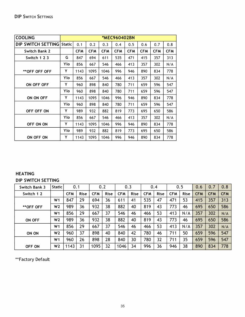
35
DIP SWITCH SETTINGS
COOLINGDIP SWITCH SETTING Static 0.1 0.2 0.3 0.4 0.5 0.6 0.7 0.8
Switch Bank 2 CFM CFM CFM CFM CFM CFM CFM CFM
Switch 1 2 3 G 847 694 611 535 471 415 357 313
Ylo 856 667 546 466 413 357 302 N/A
Y 1143 1095 1046 996 946 890 834 778
Ylo 856 667 546 466 413 357 302 N/A
Y 960 898 840 780 711 659 596 547
Ylo 960 898 840 780 711 659 596 547
Y 1143 1095 1046 996 946 890 834 778
Ylo 960 898 840 780 711 659 596 547
Y 989 932 882 819 773 695 650 586
Ylo 856 667 546 466 413 357 302 N/A
Y 1143 1095 1046 996 946 890 834 778
Ylo 989 932 882 819 773 695 650 586
Y 1143 1095 1046 996 946 890 834 778
*MEC960402BN
**OFF OFF OFF
ON OFF OFF
ON ON OFF
OFF OFF ON
OFF ON ON
ON OFF ON
HEATINGDIP SWITCH SETTING
Switch Bank 3 Static 0.6 0.7 0.8Switch 1 2 CFM Rise CFM Rise CFM Rise CFM Rise CFM Rise CFM CFM CFM
W1 847 29 694 36 611 41 535 47 471 53 415 357 313W2 989 36 932 38 882 40 819 43 773 46 695 650 586W1 856 29 667 37 546 46 466 53 413 N/A 357 302 N/A
W2 989 36 932 38 882 40 819 43 773 46 695 650 586W1 856 29 667 37 546 46 466 53 413 N/A 357 302 N/A
W2 960 37 898 40 840 42 780 46 711 50 659 596 547W1 960 26 898 28 840 30 780 32 711 35 659 596 547W2 1143 31 1095 32 1046 34 996 36 946 38 890 834 778
**Factory Default
0.40.1 0.2 0.3
**OFF OFF
ON OFF
ON ON
OFF ON
0.5
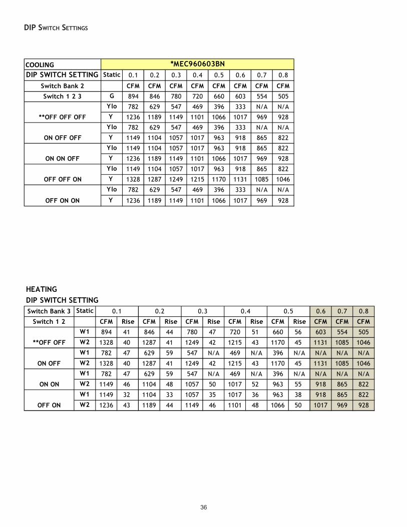
36
DIP SWITCH SETTINGS
COOLINGDIP SWITCH SETTING Static 0.1 0.2 0.3 0.4 0.5 0.6 0.7 0.8
Switch Bank 2 CFM CFM CFM CFM CFM CFM CFM CFM
Switch 1 2 3 G 894 846 780 720 660 603 554 505
Ylo 782 629 547 469 396 333 N/A N/A
Y 1236 1189 1149 1101 1066 1017 969 928
Ylo 782 629 547 469 396 333 N/A N/A
Y 1149 1104 1057 1017 963 918 865 822
Ylo 1149 1104 1057 1017 963 918 865 822
Y 1236 1189 1149 1101 1066 1017 969 928
Ylo 1149 1104 1057 1017 963 918 865 822
Y 1328 1287 1249 1215 1170 1131 1085 1046
Ylo 782 629 547 469 396 333 N/A N/A
Y 1236 1189 1149 1101 1066 1017 969 928
*MEC960603BN
OFF OFF ON
**OFF OFF OFF
ON OFF OFF
ON ON OFF
OFF ON ON
HEATINGDIP SWITCH SETTINGSwitch Bank 3 Static 0.6 0.7 0.8
Switch 1 2 CFM Rise CFM Rise CFM Rise CFM Rise CFM Rise CFM CFM CFMW1 894 41 846 44 780 47 720 51 660 56 603 554 505
W2 1328 40 1287 41 1249 42 1215 43 1170 45 1131 1085 1046
W1 782 47 629 59 547 N/A 469 N/A 396 N/A N/A N/A N/A
W2 1328 40 1287 41 1249 42 1215 43 1170 45 1131 1085 1046
W1 782 47 629 59 547 N/A 469 N/A 396 N/A N/A N/A N/A
W2 1149 46 1104 48 1057 50 1017 52 963 55 918 865 822
W1 1149 32 1104 33 1057 35 1017 36 963 38 918 865 822
W2 1236 43 1189 44 1149 46 1101 48 1066 50 1017 969 928
0.3 0.4 0.5
ON ON
OFF ON
0.1 0.2
**OFF OFF
ON OFF

37
COOLINGDIP SWITCH SETTING Static 0.1 0.2 0.3 0.4 0.5 0.6 0.7 0.8
Switch Bank 2 CFM CFM CFM CFM CFM CFM CFM CFM
Switch 1 2 3 G 1221 1172 1128 1087 1049 1005 959 922
Ylo 750 644 569 507 442 388 328 N/A
Y 1111 1068 1025 984 941 885 N/A 801
Ylo 750 644 569 507 442 388 328 N/A
Y 894 842 784 726 682 618 562 519
Ylo 894 842 784 726 682 618 562 519
Y 1111 1068 1025 984 941 885 N/A 801
Ylo 894 842 784 726 682 618 562 519
Y 1221 1172 1128 1087 1049 1005 959 922
Ylo 894 842 784 726 682 618 562 519
Y 1311 1293 1249 1203 1172 1122 1088 1041
Ylo 750 644 569 507 442 388 328 N/A
Y 1111 1068 1025 984 941 885 N/A 801
*MEC960803BN
**OFF OFF OFF
ON OFF OFF
ON ON OFF
OFF ON OFF
OFF OFF ON
OFF ON ON
HEATINGDIP SWITCH SETTINGSwitch Bank 3 Static 0.6 0.7 0.8
Switch 1 2 CFM Rise CFM Rise CFM Rise CFM Rise CFM Rise CFM CFM CFM
W1 1221 40 1172 42 1128 44 1087 45 1049 47 1005 959 922
W2 1311 54 1293 54 1249 56 1203 58 1172 60 1122 1088 1041
W1 750 66 644 N/A 569 N/A 507 N/A 442 N/A 388 328 N/A
W2 1311 54 1293 54 1249 56 1203 58 1172 60 1122 1088 1041
W1 750 66 644 N/A 569 N/A 507 N/A 442 N/A 388 328 N/A
W2 894 N/A 842 N/A 784 N/A 726 N/A 682 N/A 618 562 519
W1 894 55 842 59 784 63 726 68 682 N/A 618 562 519
W2 1111 63 1068 66 1025 69 984 72 941 75 885 N/A 801
*NOT RECOMMENDED**Factory Default
0.2 0.3 0.4 0.5
**OFF OFF
ON OFF*
ON ON*
OFF ON
0.1
DIP SWITCH SETTINGS

38
DIP SWITCH SETTINGS
COOLINGDIP SWITCH SETTING 0.1 0.2 0.3 0.4 0.5 0.6 0.7 0.8
Switch Bank 2 CFM CFM CFM CFM CFM CFM CFM CFM
Switch 1 2 3 G 1281 1220 1152 1096 1031 978 914 856
Ylo 1408 1337 1279 1218 1167 1112 1062 999
Y 1727 1691 1642 1600 1545 1504 1449 1410
Ylo 1185 1121 1058 992 933 868 808 750
Y 1727 1691 1642 1600 1545 1504 1449 1410
Ylo 1185 1121 1058 992 933 868 808 750
Y 1281 1220 1152 1096 1031 978 914 856
Ylo 1185 1121 1058 992 933 868 808 750
Y 1839 1790 1757 1699 1665 1615 1568 1527
Ylo 1408 1337 1279 1218 1167 1112 1062 999
Y 1727 1691 1642 1600 1545 1504 1449 1410
*MEC960804CN
OFF ON ON
OFF OFF ON
**OFF OFF OFF
ON ON OFF
OFF ON OFF
HEATINGDIP SWITCH SETTING
Switch Bank 3 Static 0.6 0.7 0.8
Switch 1 2 CFM Rise CFM Rise CFM Rise CFM Rise CFM Rise CFM CFM CFMW1 1281 38 1220 40 1152 43 1096 45 1031 48 978 914 856
W2 1839 38 1790 39 1757 40 1699 41 1665 42 1615 1568 1527
W1 1408 35 1337 37 1279 39 1218 40 1167 42 1112 1062 999
W2 1839 38 1790 39 1757 40 1699 41 1665 42 1615 1568 1527
W1 1408 35 1337 37 1279 39 1218 40 1167 42 1112 1062 999
W2 1185 N/A 1121 N/A 1058 N/A 992 N/A 933 N/A 868 808 750
W1 1185 42 1121 44 1058 47 992 50 933 53 868 808 519
W2 1727 41 1691 42 1642 43 1600 44 1545 46 1504 1449 1410
*NOT RECOMMENDED
0.1 0.2 0.3 0.4 0.5
**OFF OFF
ON OFF
ON ON*
OFF ON
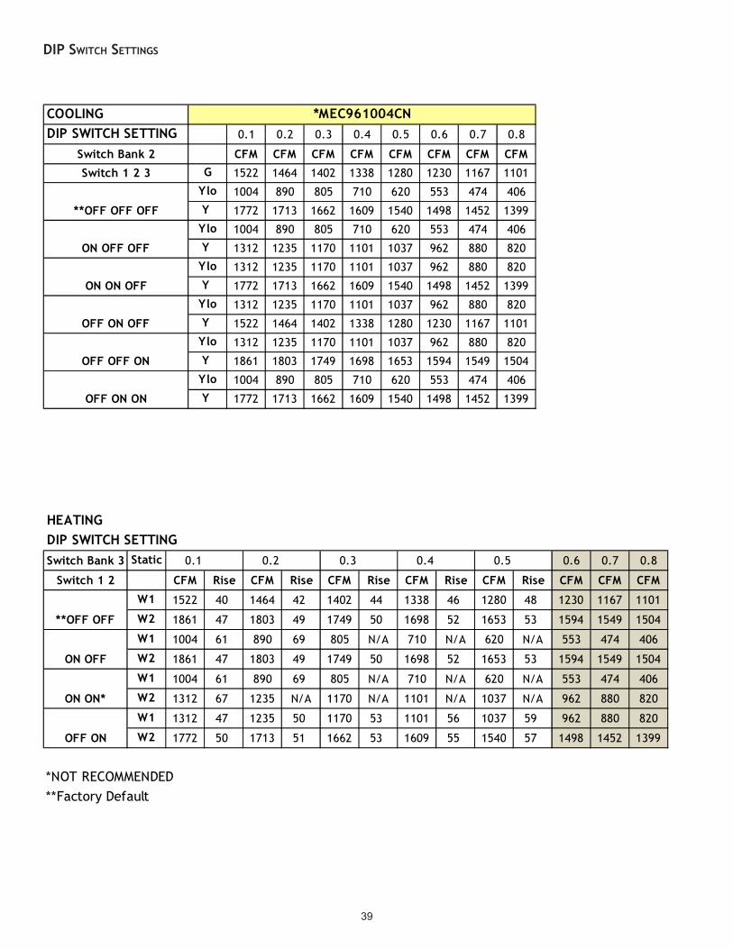
39
COOLINGDIP SWITCH SETTING 0.1 0.2 0.3 0.4 0.5 0.6 0.7 0.8
Switch Bank 2 CFM CFM CFM CFM CFM CFM CFM CFM
Switch 1 2 3 G 1522 1464 1402 1338 1280 1230 1167 1101
Ylo 1004 890 805 710 620 553 474 406
Y 1772 1713 1662 1609 1540 1498 1452 1399
Ylo 1004 890 805 710 620 553 474 406
Y 1312 1235 1170 1101 1037 962 880 820
Ylo 1312 1235 1170 1101 1037 962 880 820
Y 1772 1713 1662 1609 1540 1498 1452 1399
Ylo 1312 1235 1170 1101 1037 962 880 820
Y 1522 1464 1402 1338 1280 1230 1167 1101
Ylo 1312 1235 1170 1101 1037 962 880 820
Y 1861 1803 1749 1698 1653 1594 1549 1504
Ylo 1004 890 805 710 620 553 474 406
Y 1772 1713 1662 1609 1540 1498 1452 1399
*MEC961004CN
**OFF OFF OFF
ON OFF OFF
ON ON OFF
OFF ON OFF
OFF OFF ON
OFF ON ON
DIP SWITCH SETTINGS
HEATINGDIP SWITCH SETTINGSwitch Bank 3 Static 0.1 0.2 0.3 0.4 0.5 0.6 0.7 0.8
Switch 1 2 CFM Rise CFM Rise CFM Rise CFM Rise CFM Rise CFM CFM CFM
W1 1522 40 1464 42 1402 44 1338 46 1280 48 1230 1167 1101
W2 1861 47 1803 49 1749 50 1698 52 1653 53 1594 1549 1504
W1 1004 61 890 69 805 N/A 710 N/A 620 N/A 553 474 406
W2 1861 47 1803 49 1749 50 1698 52 1653 53 1594 1549 1504
W1 1004 61 890 69 805 N/A 710 N/A 620 N/A 553 474 406
W2 1312 67 1235 N/A 1170 N/A 1101 N/A 1037 N/A 962 880 820
W1 1312 47 1235 50 1170 53 1101 56 1037 59 962 880 820
W2 1772 50 1713 51 1662 53 1609 55 1540 57 1498 1452 1399
*NOT RECOMMENDED**Factory Default
**OFF OFF
ON OFF
ON ON*
OFF ON

40
COOLINGDIP SWITCH SETTING 0.1 0.2 0.3 0.4 0.5 0.6 0.7 0.8
Switch Bank 2 CFM CFM CFM CFM CFM CFM CFM CFM
Switch 1 2 3 G 1283 1219 1162 1101 1036 974 917 864
Ylo 1438 1366 1309 1254 1163 1133 1077 1013
Y 2008 1963 1964 1916 1876 1839 1801 1759
Ylo 1384 1324 1271 1204 1145 1088 1029 985
Y 2008 1963 1964 1916 1876 1839 1801 1759
Ylo 1384 1324 1271 1204 1145 1088 1029 985
Y 1811 1772 1733 1690 1644 1590 1551 1492
Ylo 1438 1366 1309 1254 1163 1133 1077 1013
Y 2008 1963 1964 1916 1876 1839 1801 1759
Ylo 1811 1772 1733 1690 1644 1590 1551 1492
Y 2008 1963 1964 1916 1876 1839 1801 1759
*MEC961005CN
OFF OFF ON
**OFF OFF OFF
ON ON OFF
OFF ON ON
ON OFF ON
HEATINGDIP SWITCH SETTING
Switch Bank 3 Static 0.1 0.2 0.3 0.4 0.5 0.6 0.7 0.8
Switch 1 2 CFM Rise CFM Rise CFM Rise CFM Rise CFM Rise CFM CFM CFMW1 1283 48 1219 51 1162 53 1101 56 1036 59 974 917 864
W2 1811 49 1772 50 1733 51 1690 52 1644 54 1590 1551 1492
W1 1438 43 1366 45 1309 47 1254 49 1163 53 1133 1077 1013
W2 1811 49 1772 50 1733 51 1690 52 1644 54 1590 1551 1492
W1 1438 43 1366 45 1309 47 1254 49 1163 53 1133 1077 1013
W2 1384 64 1324 N/A 1271 N/A 1204 N/A 1145 N/A 1088 1029 985
W1 1384 44 1324 47 1271 48 1204 51 1145 54 1088 1029 985
W2 2008 44 1963 45 1964 45 1916 46 1876 47 1839 1801 1759
*NOT RECOMMENDED**Factory Default
OFF ON
**OFF OFF
ON OFF
ON ON*
DIP SWITCH SETTINGS

41
DIP SWITCH SETTINGS
COOLINGDIP SWITCH SETTING 0.1 0.2 0.3 0.4 0.5 0.6 0.7 0.8
Switch Bank 2 CFM CFM CFM CFM CFM CFM CFM CFM
Switch 1 2 3 G 1796 1753 1697 1645 1589 1536 1478 1425
Ylo 1106 1017 946 855 764 681 605 N/A
Y 1683 1628 1565 1511 1445 1387 1340 1276
Ylo 1106 1017 946 855 764 681 605 N/A
Y 1399 1327 1259 1185 1118 1051 980 913
Ylo 1399 1327 1259 1185 1118 1051 980 913
Y 1683 1628 1565 1511 1445 1387 1340 1276
Ylo 1399 1327 1259 1185 1118 1051 980 913
Y 1796 1753 1697 1645 1589 1536 1478 1425
Ylo 1399 1327 1259 1185 1118 1051 980 913
Y 2211 2162 2122 2076 2029 1986 1984 1942
Ylo 1106 1017 946 855 764 681 605 N/A
Y 1683 1628 1565 1511 1445 1387 1340 1276
*MEC961205DN
**OFF OFF OFF
ON OFF OFF
ON ON OFF
OFF ON OFF
OFF OFF ON
OFF ON ON
HEATINGDIP SWITCH SETTINGSwitch Bank 3 Static 0.6 0.7 0.8
Switch 1 2 CFM Rise CFM Rise CFM Rise CFM Rise CFM Rise CFM CFM CFMW1 1796 41 1753 42 1697 44 1645 45 1589 47 1536 1478 1425
W2 2211 48 2162 49 2122 50 2076 51 2029 52 1986 1984 1942
W1 1106 67 1017 73 946 N/A 855 N/A 764 N/A 681 605 N/A
W2 2211 48 2162 49 2122 50 2076 51 2029 52 1986 1984 1942
W1 1106 67 1017 73 946 N/A 855 N/A 764 N/A 681 605 N/A
W2 1399 75 1327 N/A 1259 N/A 1185 N/A 1118 N/A 1051 980 913
W1 1399 53 1327 56 1259 59 1185 62 1118 66 1051 980 913
W2 1683 63 1628 65 1565 67 1511 70 1445 73 1387 1340 1276
*NOT RECOMMENDED**Factory Default
ON ON*
OFF ON
0.1 0.2
**OFF OFF
ON OFF
0.3 0.4 0.5
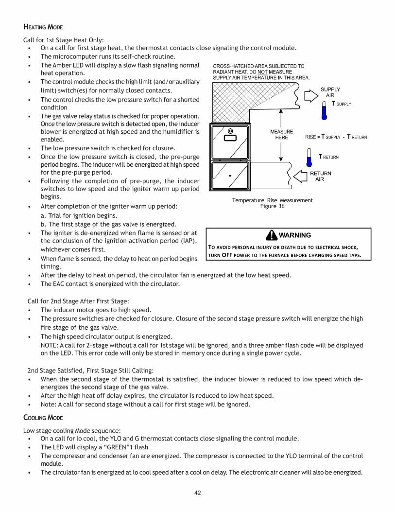
42
HEATING MODE
Call for 1st Stage Heat Only:• On a call for first stage heat, the thermostat contacts close signaling the control module.• The microcomputer runs its self-check routine.• The Amber LED will display a slow flash signaling normal
heat operation.• The control module checks the high limit (and/or auxiliary
limit) switch(es) for normally closed contacts.• The control checks the low pressure switch for a shorted
condition• The gas valve relay status is checked for proper operation.
Once the low pressure switch is detected open, the inducerblower is energized at high speed and the humidifier isenabled.
• The low pressure switch is checked for closure.• Once the low pressure switch is closed, the pre-purge
period begins. The inducer will be energized at high speedfor the pre-purge period.
• Following the completion of pre-purge, the inducerswitches to low speed and the igniter warm up periodbegins.
• After completion of the igniter warm up period:a. Trial for ignition begins.b. The first stage of the gas valve is energized.
• The igniter is de-energized when flame is sensed or atthe conclusion of the ignition activation period (IAP),whichever comes first.
• When flame is sensed, the delay to heat on period beginstiming.
• After the delay to heat on period, the circulator fan is energized at the low heat speed.• The EAC contact is energized with the circulator.
Call for 2nd Stage After First Stage:• The inducer motor goes to high speed.• The pressure switches are checked for closure. Closure of the second stage pressure switch will energize the high
fire stage of the gas valve.• The high speed circulator output is energized.
NOTE: A call for 2nd stage without a call for 1st stage will be ignored, and a three amber flash code will be displayedon the LED. This error code will only be stored in memory once during a single power cycle.
2nd Stage Satisfied, First Stage Still Calling:• When the second stage of the thermostat is satisfied, the inducer blower is reduced to low speed which de-
energizes the second stage of the gas valve.• After the high heat off delay expires, the circulator is reduced to low heat speed.• Note: A call for second stage without a call for first stage will be ignored.
COOLING MODE
Low stage cooling Mode sequence:• On a call for lo cool, the YLO and G thermostat contacts close signaling the control module.• The LED will display a “GREEN”1 flash• The compressor and condenser fan are energized. The compressor is connected to the YLO terminal of the control
module.• The circulator fan is energized at lo cool speed after a cool on delay. The electronic air cleaner will also be energized.
SUPPLY AIR
RETURN AIR
Temperature Rise MeasurementFigure 36
TO AVOID PERSONAL INJURY OR DEATH DUE TO ELECTRICAL SHOCK, TURN OFF POWER TO THE FURNACE BEFORE CHANGING SPEED TAPS.
WARNING

43
• After the thermostat is satisfied, the compressor is de-energized and the 45 second fan off delay period begins.
• Following the 45 second cool mode fan off delay period, thecool circulator and air cleaner relay are de-energized.
Single cooling stage thermostat or 2nd stage cooling Mode sequence:• On a call for cool, the Y and G thermostat contacts close
signaling the control module.• The LED will display a “GREEN”2 flash• The compressor and condenser fan are energized. The circulator
fan is energized at cool speed after a cool on delay. The electronic air cleaner will also be energized.• After the thermostat is satisfied, the compressor is de-energized and the fan off delay period begins.• Following the 45 second fan off delay period, the cool circulator and air cleaner relay are de-energized.
Note: If a call for both YLO and Y are present, Y will have priority.
FAN ONLY MODE
MANUAL FAN ON:• Call for continuous fan (24 volts on the furnace “G” terminal.)• The LED will display rapid “GREEN”.• The circulator blower is energized at low heat speed and the electronic air cleaner is also energized after the fan on
delay period has expired.
OPERATIONAL CHECKS
The burner flames should be inspected with the burner compartment door installed. Flames should be stable, quiet, soft, and blue(dust may cause orange tips but they must not be yellow). Flames should extend directly outward from the burners without curling,floating, or lifting off. Flames must not impinge on the sides of the heat exchanger firing tubes.
SAFETY CIRCUIT DESCRIPTION
A number of safety circuits are employed to ensure safe and proper furnace operation. These circuits serve to control any potentialsafety hazards and serve as inputs in the monitoring and diagnosis of abnormal function. These circuits are continuously monitoredduring furnace operation by the integrated control module.
INTEGRATED CONTROL MODULE
The integrated control module is an electronic device which, if a potential safety concern is detected, will take the necessaryprecautions and provide diagnostic information through an LED.
PRIMARY LIMIT
The primary limit control is located on the partition panel and monitors heat exchanger compartment temperatures. It is a normally-closed (electrically), automatic reset, temperature-activated sensor. The limit guards against overheating as a result of insufficientconditioned air passing over the heat exchanger.
AUXILIARY LIMIT
The auxiliary limit controls are located on or near the circulator blower and monitors blower compartment temperatures. They area normally-closed (electrically), manual-reset sensors. These limits guard against overheating as a result of insufficient conditionedair passing over the heat exchanger.
ROLLOUT LIMIT
The rollout limit controls are mounted on the burner/manifold assembly and monitor the burner flame. They are normally-closed(electrically), manual-reset sensors. These limits guard against burner flames not being properly drawn into the heat exchanger.
PRESSURE SWITCHES
The pressure switches are normally-open (closed during operation) negative air pressure-activated switches. They monitor theairflow (combustion air and flue products) through the heat exchanger via pressure taps located on the induced draft blower and thecoil front cover. These switches guard against insufficient airflow (combustion air and flue products) through the heat exchangerand/or blocked condensate drain conditions.
DIP Switch Group
DIP Switch
NumberPurpose
90 Seconds 3 OFF 4 OFF
120 Seconds 3 OFF 4 ON
150 Seconds 3 ON* 4 OFF*
180 Seconds 3 ON* 4 ON* = Factory Pos i tion
Function
SI 3, 4Blower
Heat Off Delay
44
FLAME SENSOR
The flame sensor is a probe mounted to the burner/manifold assembly which uses the principle of flame rectification to determine thepresence or absence of flame.
TROUBLESHOOTING
ELECTROSTATIC DISCHARGE (ESD) PRECAUTIONS
NOTE: Discharge body’s static electricity before touching unit. An electrostatic discharge can adversely affect electrical components.
Use the following precautions during furnace installation and servicing to protect the integrated control module from damage. Byputting the furnace, the control, and the person at the same electrostatic potential, these steps will help avoid exposing the inte-grated control module to electrostatic discharge. This procedure is applicable to both installed and uninstalled (ungrounded) furnaces.1. Disconnect all power to the furnace. Do not touch the integrated control module or any wire connected to the control prior to
discharging your body’s electrostatic charge to ground.2. Firmly touch a clean, unpainted, metal surface of the furnace away from the control. Any tools held in a person’s hand during
grounding will be discharged.3. Service integrated control module or connecting wiring following the discharge process in step 2. Use caution not to recharge
your body with static electricity; (i.e., do not move or shuffle your feet, do not touch ungrounded objects, etc.). If you comein contact with an ungrounded object, repeat step 2 before touching control or wires.
4. Discharge your body to ground before removing a new control from its container. Follow steps 1 through 3 if installing thecontrol on a furnace. Return any old or new controls to their containers before touching any ungrounded object.
CHECKING FLAME SENSOR
Flame current can be measured in two ways:1. Putting a D.C. microamp meter in series with the flame rod2. Putting a D.C. volt meter across the two solder pads in the flame current section of the control board.
1 D.C. volt = 1 microamp. See Figure 37.
LIMIT FAULT CODES
If the control detects the high limit circuit open, the RED LED will flash FOUR times and energize the inducer and indoorblower.
If the limit circuit opens five times within a single call for heat, the furnace will go into lockout for one hour. The RED LED willdisplay a FOUR flash code during this time. The control board can be reset by cycling 115 volt power to the furnace.
If the limit circuit opens and does not close within five minutes, the control assumes the blower has failed the RED LED willflash ELEVEN times.
If the limit circuit opens and does not close within fifteen minutes, the control assumes the manual rollout or fuse has openedand the RED LED will flash FIVE times. The control will enter a one hour lockout and the inducer will run continuously.
In an open limit condition the red LED will flash as described above but the error code will not be stored in memory until thelimit resets or until 15 minutes has elapsed. So if the limit resets in less than 5 minutes a four flash code will be stored. If thelimit resets in more than 5 but less than 15 minutes, an eleven flash code will be stored. If the limit is still open after 15minutes, a five flash code will be stored.
DIAGNOSTIC CHART
Refer to the Troubleshooting Chart in the back of this manual for assistance in determining the source of unit operational problems.
External Lockout- A control lockout resulting from an external fault sensed by the control, such as an unsuccessful recycle or retry
period, or a limit trip. Once in External Lockout, the control will shut down for a period of one hour beforeattempting another trial for ignition.
Internal Lockout- A failure internal to the control board.

45
FAULT RECALL
Retrieving Fault Codes
To retrieve fault codes, push and release the “LAST ERROR” button for more than 1/5 second and less than 5 seconds (theLED will indicate this period by solid GREEN for 1/5 second to 5 seconds). The LED will flash up to five stored fault codes,beginning with the most recent. If there are no fault codes in memory, the LED will flash two green flashes. The control willflash the most recent error first and the oldest error last. If multiple faults exist there will be 2 seconds between codes. SolidLED error codes will not be displayed.
Fault Code Reset
To clear the fault code memory, push and hold the “LAST ERROR” button for more than 5 seconds and less than 10 seconds(the LED will indicate this period by RAPID GREEN FLASH for 5 seconds to 10 seconds). The LED will flash three green flasheswhen the memory has been cleared.
The ignition control is equipped with a momentary push button switch that can be used to display on the diagnostic LED thelast five faults detected by the control. The control must be in Standby Mode (no thermostat inputs) to use the feature.Depress the push button switch for approximately 2 seconds. Release the switch when the LED is turned off. The diagnosticLED will then display the flash codes associated with the last five detected faults. The order of display is the most recent faultto the least recent fault.
RESETTING FROM LOCKOUT
Furnace lockout results when a furnace is unable to achieve ignition after three attempts during a single call for heat. It ischaracterized by a non-functioning furnace and a one flash diagnostic LED code. If the furnace is in “lockout”, it can be resetin any of the following ways.1. Automatic reset. The integrated control module will automatically reset itself and attempt to resume normal operations
following a one hour lockout period.2. Manual power interruption. Interrupt 115 volt power to the furnace for 1 - 20 seconds.3. Manual thermostat cycle. Lower the thermostat so that there is no longer a call for heat then reset to previous
setting. Interrupt thermostat signal to the furnace for 1 - 20 seconds.
NOTE: If the condition which originally caused the lockout still exists, the control will return to lockout. Refer to the TroubleshootingChart for aid in determining the cause.
MAINTENANCE
ANNUAL INSPECTION
The furnace should be inspected by a qualified installer, or service agency at leastonce per year. This check should be performed at the beginning of the heatingseason. This will ensure that all furnace components are in proper working orderand that the heating system functions appropriately. Pay particular attention to thefollowing items. Repair or service as necessary.
• Flue pipe system. Check for blockage and/or leakage. Check the outsidetermination and the connections at and internal to the furnace.
• Heat exchanger. Check for corrosion and/or buildup within the heat exchangerpassageways.
• Burners. Check for proper ignition, burner flame, and flame sense.• Drainage system. Check for blockage and/or leakage. Check hose connections
at and internal to furnace.• Wiring. Check electrical connections for tightness and/or corrosion. Check
wires for damage.• Filters.
Flame CurrentSolder Pads
Figure 37
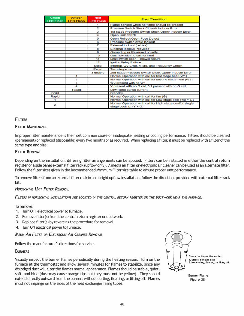
46
Burner FlameFigure 38
FILTERS
FILTER MAINTENANCE
Improper filter maintenance is the most common cause of inadequate heating or cooling performance. Filters should be cleaned(permanent) or replaced (disposable) every two months or as required. When replacing a filter, it must be replaced with a filter of thesame type and size.
FILTER REMOVAL
Depending on the installation, differing filter arrangements can be applied. Filters can be installed in either the central returnregister or a side panel external filter rack (upflow only). A media air filter or electronic air cleaner can be used as an alternate filter.Follow the filter sizes given in the Recommended Minimum Filter size table to ensure proper unit performance.
To remove filters from an external filter rack in an upright upflow installation, follow the directions provided with external filter rackkit.
HORIZONTAL UNIT FILTER REMOVAL
FILTERS IN HORIZONTAL INSTALLATIONS ARE LOCATED IN THE CENTRAL RETURN REGISTER OR THE DUCTWORK NEAR THE FURNACE.
To remove:1. Turn OFF electrical power to furnace.2. Remove filter(s) from the central return register or ductwork.3. Replace filter(s) by reversing the procedure for removal.4. Turn ON electrical power to furnace.
MEDIA AIR FILTER OR ELECTRONIC AIR CLEANER REMOVAL
Follow the manufacturer’s directions for service.
BURNERS
Visually inspect the burner flames periodically during the heating season. Turn on thefurnace at the thermostat and allow several minutes for flames to stabilize, since anydislodged dust will alter the flames normal appearance. Flames should be stable, quiet,soft, and blue (dust may cause orange tips but they must not be yellow). They shouldextend directly outward from the burners without curling, floating, or lifting off. Flamesmust not impinge on the sides of the heat exchanger firing tubes.
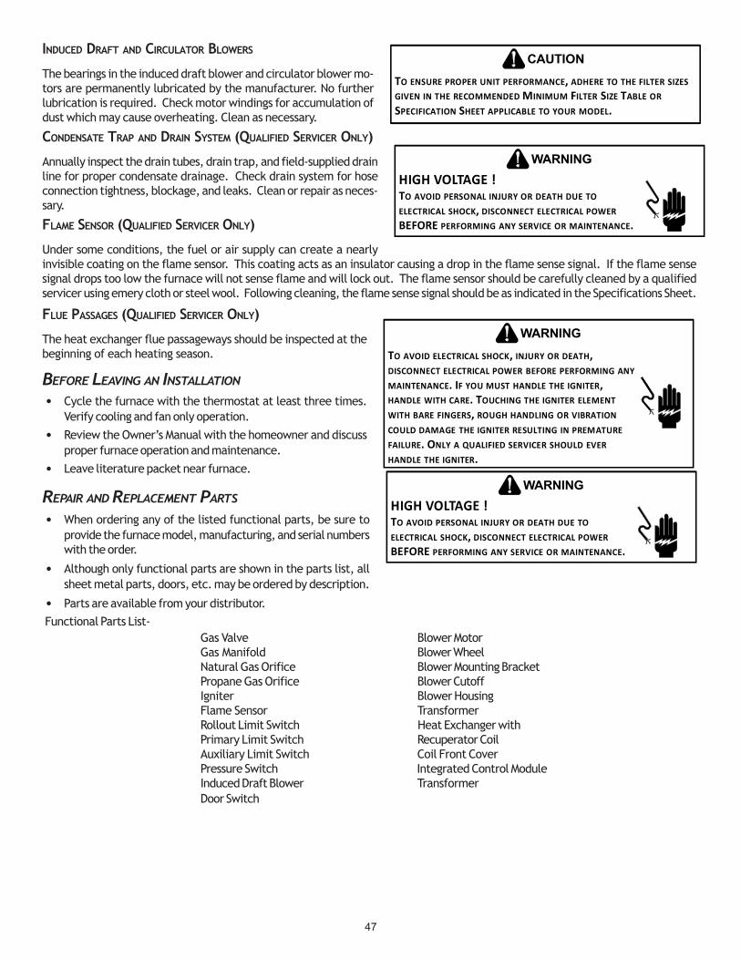
47
INDUCED DRAFT AND CIRCULATOR BLOWERS
The bearings in the induced draft blower and circulator blower mo-tors are permanently lubricated by the manufacturer. No furtherlubrication is required. Check motor windings for accumulation ofdust which may cause overheating. Clean as necessary.
CONDENSATE TRAP AND DRAIN SYSTEM (QUALIFIED SERVICER ONLY)
Annually inspect the drain tubes, drain trap, and field-supplied drainline for proper condensate drainage. Check drain system for hoseconnection tightness, blockage, and leaks. Clean or repair as neces-sary.
FLAME SENSOR (QUALIFIED SERVICER ONLY)
Under some conditions, the fuel or air supply can create a nearlyinvisible coating on the flame sensor. This coating acts as an insulator causing a drop in the flame sense signal. If the flame sensesignal drops too low the furnace will not sense flame and will lock out. The flame sensor should be carefully cleaned by a qualifiedservicer using emery cloth or steel wool. Following cleaning, the flame sense signal should be as indicated in the Specifications Sheet.
FLUE PASSAGES (QUALIFIED SERVICER ONLY)
The heat exchanger flue passageways should be inspected at thebeginning of each heating season.
BEFORE LEAVING AN INSTALLATION
• Cycle the furnace with the thermostat at least three times.Verify cooling and fan only operation.
• Review the Owner’s Manual with the homeowner and discussproper furnace operation and maintenance.
• Leave literature packet near furnace.
REPAIR AND REPLACEMENT PARTS
• When ordering any of the listed functional parts, be sure toprovide the furnace model, manufacturing, and serial numberswith the order.
• Although only functional parts are shown in the parts list, allsheet metal parts, doors, etc. may be ordered by description.
• Parts are available from your distributor.Functional Parts List-
Gas Valve Blower MotorGas Manifold Blower WheelNatural Gas Orifice Blower Mounting BracketPropane Gas Orifice Blower CutoffIgniter Blower HousingFlame Sensor TransformerRollout Limit Switch Heat Exchanger withPrimary Limit Switch Recuperator CoilAuxiliary Limit Switch Coil Front CoverPressure Switch Integrated Control ModuleInduced Draft Blower TransformerDoor Switch
HIGH VOLTAGE !TO AVOID PERSONAL INJURY OR DEATH DUE TO ELECTRICAL SHOCK, DISCONNECT ELECTRICAL POWER BEFORE PERFORMING ANY SERVICE OR MAINTENANCE.
WARNING
TO ENSURE PROPER UNIT PERFORMANCE, ADHERE TO THE FILTER SIZES GIVEN IN THE RECOMMENDED MINIMUM FILTER SIZE TABLE OR SPECIFICATION SHEET APPLICABLE TO YOUR MODEL.
CAUTION
TO AVOID ELECTRICAL SHOCK, INJURY OR DEATH, DISCONNECT ELECTRICAL POWER BEFORE PERFORMING ANY MAINTENANCE. IF YOU MUST HANDLE THE IGNITER, HANDLE WITH CARE. TOUCHING THE IGNITER ELEMENT WITH BARE FINGERS, ROUGH HANDLING OR VIBRATION COULD DAMAGE THE IGNITER RESULTING IN PREMATURE FAILURE. ONLY A QUALIFIED SERVICER SHOULD EVER HANDLE THE IGNITER.
WARNING
HIGH VOLTAGE !TO AVOID PERSONAL INJURY OR DEATH DUE TO ELECTRICAL SHOCK, DISCONNECT ELECTRICAL POWER BEFORE PERFORMING ANY SERVICE OR MAINTENANCE.
WARNING
48
THIS PAGE INTENTIONALLY LEFT BLANK
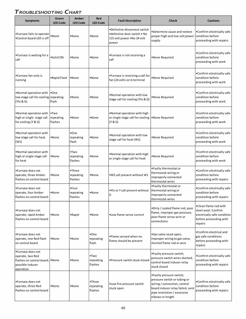
49
TROUBLESHOOTING CHART
SymptomsGreen
LED CodeAmber
LED CodeRed
LED CodeFault Description Check Cautions
•Furnace fails to operate •Control board LED is off
•None •None •None
•Defective disconnect switch •defective door switch • No 115 volt power •No 24 volt power
•Determine cause and restore proper high and low volt power supply
•Confirm electrically safe condition before proceeding with repairs
•Furnace is waiting for a call
•Solid ON •None •None•Furnace is not receiving a call
•None Required•Confirm electrically safe condition before proceeding with work
•Furnace fan only is running
•Rapid Flash •None •None•Furnace is receiving a call for fan (24 volts on G terminal
•None Required•Confirm electrically safe condition before proceeding with work
•Normal operation with low stage call for cooling (Ylo & G)
•One repeating flash
•None •None•Normal operation with low stage call for cooling (Ylo & G)
•None Required•Confirm electrically safe condition before proceeding with work
•Normal operation with high or single stage call for cooling (Y & G)
•Two repeating flashes
•None •None•Normal operation with high or single stage call for cooling (Y & G)
•None Required•Confirm electrically safe condition before proceeding with work
•Normal operation with low stage call for heat (W1)
•None•One repeating flash
•None•Normal operation with low stage call for heat (W1)
•None Required•Confirm electrically safe condition before proceeding with work
•Normal operation with high or single stage call for heat
•None•Two repeating flashes
•None•Normal operation with high or single stage call for heat
•None Required•Confirm electrically safe condition before proceeding with work
•Furnace does not operate, three Amber flashes on control board
•None•Three repeating flashes
•None •W2 call present without W1
•Faulty thermostat or thermostat wiring or improperly connected thermostat wires
•Confirm electrically safe condition before proceeding with repairs
•Furnace does not operate, four Amber flashes on control board
•None•Four repeating flashes
•None•Ylo or Y call present without G
•Faulty thermostat or thermostat wiring or improperly connected thermostat wires
•Confirm electrically safe condition before proceeding with repairs
•Furnace does not operate, rapid Amber flashes on control board
•None •Rapid •None •Low flame sense current
•Dirty / coated flame rod, poor flame, improper gas pressure, poor flame sense wire or connections
•Clean flame rod with steel wool. Confirm electrically safe condition before proceeding with repairs
•Furnace does not operate, one Red flash on control board
•None •None•One repeating flash
•Flame sensed when no flame should be present
•Gas valve stuck open, improper wiring to gas valve, shorted flame rod or wire
•Confirm electrical and gas safe conditions before proceeding with repairs
•Furnace does not operate, two Red flashes on control board, possible inducer operation
•None •None•Two repeating flashes
•Pressure switch stuck closed
•Faulty pressure switch, pressure switch wires shorted, control board inducer relay stuck closed
•Confirm electrically safe condition before proceeding with repairs
•Furnace does not operate, three Red flashes on control board
•None •None•Three repeating flashes
•Low fire pressure switch stuck open
•Faulty pressure switch, pressure switch or tubing or wiring / connection, control board inducer relay failed, vent pipe restriction / excessive elbows or length
•Confirm electrically safe condition before proceeding with repairs
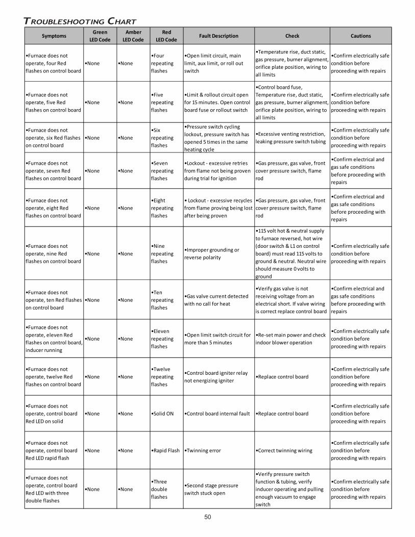
50
TROUBLESHOOTING CHARTAssociatedLED Code2Symptoms
Green LED Code
AmberLED Code
RedLED Code
Fault Description Check Cautions
•Furnace does not operate, four Red flashes on control board
•None •None•Four repeating flashes
•Open limit circuit, main limit, aux limit, or roll out switch
•Temperature rise, duct static, gas pressure, burner alignment, orifice plate position, wiring to all limits
•Confirm electrically safe condition before proceeding with repairs
•Furnace does not operate, five Red flashes on control board
•None •None•Five repeating flashes
•Limit & rollout circuit open for 15 minutes. Open control board fuse or rollout switch
•Control board fuse, Temperature rise, duct static, gas pressure, burner alignment, orifice plate position, wiring to all limits
•Confirm electrically safe condition before proceeding with repairs
•Furnace does not operate, six Red flashes on control board
•None •None•Six repeating flashes
•Pressure switch cycling lockout, pressure switch has opened 5 times in the same heating cycle
•Excessive venting restriction, leaking pressure switch tubing
•Confirm electrically safe condition before proceeding with repairs
•Furnace does not operate, seven Red flashes on control board
•None •None•Seven repeating flashes
•Lockout - excessive retries from flame not being proven during trial for ignition
•Gas pressure, gas valve, front cover pressure switch, flame rod
•Confirm electrical and gas safe conditions before proceeding with repairs
•Furnace does not operate, eight Red flashes on control board
•None •None•Eight repeating flashes
• Lockout - excessive recycles from flame proving being lost after being proven
•Gas pressure, gas valve, front cover pressure switch, flame rod
•Confirm electrical and gas safe conditions before proceeding with repairs
•Furnace does not operate, nine Red flashes on control board
•None •None•Nine repeating flashes
•Improper grounding or reverse polarity
•115 volt hot & neutral supply to furnace reversed, hot wire (door switch & L1 on control board) must read 115 volts to ground & neutral. Neutral wire should measure 0 volts to ground
•Confirm electrically safe condition before proceeding with repairs
•Furnace does not operate, ten Red flashes on control board
•None •None•Ten repeating flashes
•Gas valve current detected with no call for heat
•Verify gas valve is not receiving voltage from an electrical short. If valve wiring is correct replace control board
•Confirm electrical and gas safe conditions before proceeding with repairs
•Furnace does not operate, eleven Red flashes on control board, inducer running
•None •None•Eleven repeating flashes
•Open limit switch circuit for more than 5 minutes
•Re-set main power and check indoor blower operation
•Confirm electrically safe condition before proceeding with repairs
•Furnace does not operate, twelve Red flashes on control board
•None •None•Twelve repeating flashes
•Control board igniter relay not energizing igniter
•Replace control board•Confirm electrically safe condition before proceeding with repairs
•Furnace does not operate, control board Red LED on solid
•None •None •Solid ON •Control board internal fault •Replace control board•Confirm electrically safe condition before proceeding with repairs
•Furnace does not operate, control board Red LED rapid flash
•None •None •Rapid Flash •Twinning error •Correct twinning wiring•Confirm electrically safe condition before proceeding with repairs
•Furnace does not operate, control board Red LED with three double flashes
•None •None•Three double flashes
•Second stage pressure switch stuck open
•Verify pressure switch function & tubing, verify inducer operating and pulling enough vacuum to engage switch
•Confirm electrically safe condition before proceeding with repairs

51
HIG
H V
OLT
AG
E!
Dis
co
nn
ec
t A
LL
po
we
r b
efo
re s
erv
icin
g o
r in
sta
llin
g t
his
un
it.
Mu
ltip
lep
ow
er
so
urc
es
ma
y b
e p
res
en
t. F
ail
ure
to
do
so
ma
y c
au
se
pro
pe
rty
da
ma
ge
, p
ers
on
al i
nju
ry o
r d
eath
.
Wiring is subject to change. Always refer to the wiring diagram on the unit for the most up-to-date wiring.
WIRING DIAGRAM
GN
GND
COLOR CODES:
GN GREEN
RD REDGY GRAY
PU PURPLE
PK PINK
BK BLACK
BL BLUEWH WHITEBR BROWN
YL YELLOWOR ORANGE
GND
BK
RD
RD
GN
GN
24VAC
115VAC
GND
GR
D
BK
YLO Y W1 W2 R G C TWINN.E.C. CLASS 2 WIRE
0140F02058-A
BRPK
GY
OR
GN
BL
YL
S1
BK
HU
MX
-FMRL1
CIR
C-H
EA
C-H
5
21
43
24 V 3 AFUSE
NEUTRAL
DIAGNOSTIC
LED'S
5 CIR
CU
IT CO
NN
ECTO
R
10
63
4
52
7
11
1
12
8
9
FRONT COVERPRESSURESWITCH
NOC
FUSE 3 A
MICROTO
PS2 (2)
TR (9)
G
HI
C
TH (5)
24V TH
ER
MO
STA
T CO
NN
ECTIO
NS
N.E
.C. C
LAS
S 2 W
IRE
VALVEGAS
W2
TRANSFORMER
HLI (6)
Y2
Y1 HLO (11)
GND (4)
O
MVL (7)
NO
W1
C
R
CONTROLSAUTO RESET AUXILIARY LIMIT
LIMIT CONTROLSMANUAL RESET ROLLOUTPRESS. SWTICH
HIGH FIRE
C
SWITCHLOW FIRE PRESS
MVH (1)
DEHUM
GND
PS1 (12)
LIMIT CONTROLAUTO RESET PRIMARY24 VAC
NO
PM
MVC (8)
INTEGRATED CONTROL MODULE
C
BLWR
AIRINDOOR
CIRCULATOR
RTO
MICROTO
TO+VDC
EAC
HUMIDIFIER
ID
NEUTRAL
WIRING TO UNIT
L
INTE
GR
ATE
D C
ON
TRO
L MODU
LE
HOT SURFACE
GND
BLWR
NEUTRAL
WARNING:
GROUNDED.
OVERCURRENT PROTECTION DEVICE
MUST BE PROPERLY
SWITCH
NEUTRAL
ELECTRONIC
AIR
IGN
IND HI
DISCONNECT
FS
POLARIZED AND
NEUTRAL
LINE
NEUTRAL
JUNCTION BOX
BLWR
IND LO
N
INDOOR
AIR CLEANER
HUM
DOOR
NEUTRAL
INTE
GR
ATE
D C
ON
TRO
L MODU
LE
TO 115VAC/ 1Ø /60 HZ POWER SUPPLY WITH
115 VAC
HUM-OUT
IGNITER
CIRCULATOR
BEFORE SERVICING.
FLAME SENSOR
DISCONNECT POWER
LINE
GND
T4
T1T2
OR
BR
BK WH
WH
WH
WH
PU
GY
YL
OR
BR
PK
RD
WH B
K
PU
GY
BR
OR
RDBK
ORBL
RD
WH
WH
T3
CO
M
LINE
NO
LIMIT CONTROLAUXILIARYAUTO RESET
PK
WARNING:DISCONNECT
TRA
NS
FOR
ME
R40
VA
PU
GY
NNO
3
1
SWITCHPRESSURELOW FIRE
SENSORFLAME
PRESSURE SWITCHFRONT COVER
C TO UNIT MUST BE
BL
RD
AND GROUNDED.
1
JUN
CTIO
NB
OX
WH
SWITCH (PRESS.)
FIELD SPLICEFIELD GND
3
GN
BL
BR
WH
NO
LIMIT CONTROLAUTO RESET PRIMARY
WH
1
OR
30 kBTU AND 40 kBTU)CONTROLS (SINGLE CONTROL ONMANUAL RESET ROLLOUT LIMIT
WH
L
PU
GY
BK
SWITCH ASSEMBLYID BLOWER TWO-STAGE PRESSURE
OR
WH
SERVICING. WIRING
EQUIPMENT GND
INTERNAL TO
SWITCHPRESSUREHIGH FIRE
PROT. DEVICE
INTEGRATED CONTROL
PK
PU
PLUG CONNECTION
2
4
BK
C
DOOR OPEN)(OPEN WHENDOOR SWITCHCOMPARTMENTBLOWER
SWITCH (TEMP.)
GND
1
BLOWERCIRCULATOR
JUNCTION
OR
40 VA
Ø /60 HZ
DISCONNECT
(WHITE RODGERS)GAS VALVETWO STAGE
OVERCURRENT
CONNECTOR2 CIRCUIT
LOW VOLTAGE (24V)
YL
GND
WH
CH
AS
SIS
GR
OU
ND2
3
IGNITERSURFACE
HOT
2
YL
PU
C2
C
BLOWERDRAFT
INDUCED
BK
PM
BK
BLOWER COMPARTMENT
115 VAC/ 1
OVERCURRENT
BK
HARNESSECM MTR
HI
TERMINAL
OR
POWER BEFORE
IGNITER
RD
BK
TO
RD
POWER SUPPLY WITH
BURNER COMPARTMENT
PROTECTION DEVICE
PROPERLY POLARIZED
RDBK
ORBL
LOW VOLTAGE FIELDHI VOLTAGE (115V)HI VOLTAGE FIELD
RAPID = TWINNING ERROR
STEADY ON = INTERNAL GV ERROR, MICRO AND FREQUENCY CHECK
1 FLASH = FLAME SENSED WHEN NO FLAME SHOULD BE PRESENT
4 FLASHES = OPEN LIMIT SWITCH
0
4
3
2
1
RED LED FLASH CODE
2 FLASHES = PRESSURE SWITCH STUCK CLOSED/INDUCER ERROR
3 FLASHES = 1ST STAGE PRESSURE SWITCH STUCKOPEN/INDUCER ERROR
5 FLASHES = OPEN ROLLOUT/OPEN FUSE DETECTED
6 FLASHES = PRESSURE SWITCH CYCLE LOCKOUT
7 FLASHES = EXTERNAL LOCKOUT (RETRIES)
9
6
5
7
8 8 FLASHES = EXTERNAL LOCKOUT (RECYCLES)
9 FLASHES + GROUNDING OR REVERSED POLARITY
10 FLASHES = GAS FLOW WITH NO CALL FOR HEAT
11 FLASHES = LIMIT SWITCH OPEN-BLOWER FAILURE
12 FLASHES = IGNITOR RELAY FAILURE
11
10
12
3 DOUBLE FLASHES = 2ND STAGE PRESSURE SWITCHSTUCK OPEN/INDUCER ERROR
3 FLASHES = W2 PRESENT WITH NO W1
2 FLASHES = NORMAL OPERATION WITHCALL FOR 2ND STAGE HEAT
1 FLASH = NORMAL OPERATION WITH CALL FOR1ST STAGE HEAT (W1)
2
4
3
1
4 FLASHES = Y PRESENT WITH NO G CALL, YLOPRESENT WITH NO G CALL
AMBER LED FLASH CODE
RAPID = LOW FLAME SENSE CURRENT
RAPID = NORMAL OPERATION WITH CALL FOR FAN (G)
STEADY ON = STANDBY
1 FLASH = NORMAL OPERATION WITH CALL FORLOW STAGE COOL (YLO + G)
0
2
1
GREEN LED FLASH CODE
2 FLASHES = NORMAL OPERATION WITH CALL FOR HIGHSTAGE COOL/ OR SINGLE STAGE COOLING (Y + G)
0
1. SET HEAT ANTICIPATOR ON ROOM THERMOSTAT AT 0.7 AMPS.NOTES:
$
2. MANUFACTURER'S SPECIFIED REPLACEMENT PARTS MUST BE USEDWHEN SERVICING.
MUST BE REPLACED IT MUST BE REPLACED WITH WIRING MATERIALHAVING A TEMPERATURE RATING OF AT LEAST 105 C. USE COPPERCONDUCTORS ONLY.
4. UNIT MUST BE PERMANENTLY GROUNDED AND CONFORM TO N.E.C.AND LOCAL CODES.
5. TO RECALL THE LAST 6 FAULTS, MOST RECENT TO LEAST RECENT,DEPRESS SWITCH FOR MORE THAN 2 SECONDS WHILE IN STANDBY(NO THERMOSTAT INPUTS)
3. IF ANY OF THE ORIGINAL WIRE AS SUPPLIED WITH THE FURNACE
S2
S3

52
For all side wall horizontally vented gas fueled equipment in-stalled in every dwelling, building or structure used in whole orin part for residential purposes, including those owned or op-erated by the Commonwealth and where the side wall exhaustvent termination is less than seven (7) feet above finished gradein the area of the venting, including but not limited to decksand porches, the following requirements shall be satisfied:
1. INSTALLATION OF CARBON MONOXIDE DETECTORS. At thetime of installation of the side wall horizontal vented gasfueled equipment, the installing plumber or gasfitter shallobserve that a hard wired carbon monoxide detector withan alarm and battery back-up is installed on the floor levelwhere the gas equipment is to be installed. In addition, theinstalling plumber or gasfitter shall observe that a batteryoperated or hard wired carbon monoxide detector with analarm is installed on each additional level of the dwelling,building or structure served by the side wall horizontalvented gas fueled equipment. It shall be the responsibilityof the property owner to secure the services of qualified licensed professionals for the installation of hard wired carbonmonoxide detectors
a. In the event that the side wall horizontally vented gas fueled equipment is installed in a crawl space or an attic, the hardwired carbon monoxide detector with alarm and battery back-up may be installed on the next adjacent floor level.
b. In the event that the requirements of this subdivision can not be met at the time of completion of installation, the ownershall have a period of thirty (30) days to comply with the above requirements; provided, however, that during said thirty (30)day period, a battery operated carbon monoxide detector with an alarm shall be installed.
2. APPROVED CARBON MONOXIDE DETECTORS. Each carbon monoxide detector as required in accordance with the aboveprovisions shall comply with NFPA 720 and be ANSI/UL 2034 listed and IAS certified.
3. SIGNAGE. A metal or plastic identification plate shall be permanently mounted to the exterior of the building at a minimumheight of eight (8) feet above grade directly in line with the exhaust vent terminal for the horizontally vented gas fueledheating appliance or equipment. The sign shall read, in print size no less than one-half (1/2) inch in size, “GAS VENT DIRECTLYBELOW. KEEP CLEAR OF ALL OBSTRUCTIONS”.
4. INSPECTION. The state or local gas inspector of the side wall horizontally vented gas fueled equipment shall not approve theinstallation unless, upon inspection, the inspector observes carbon monoxide detectors and signage installed in accordancewith the provisions of 248 CMR 5.08(2)(a)1 through 4.
EXEMPTIONS
The following equipment is exempt from 248 CMR 5.08(2)(a)1 through 4:1. The equipment listed in Chapter 10 entitled “Equipment Not Required To Be Vented” in the most current edition of NFPA 54
as adopted by the Board; and2. Product Approved side wall horizontally vented gas fueled equipment installed in a room or structure separate from the
dwelling, building or structure used in whole or in part for residential purposes.(c) MANUFACTURER REQUIREMENTS - GAS EQUIPMENT VENTING SYSTEM PROVIDED. When the manufacturer of Product Approved
side wall horizontally vented gas equipment provides a venting system design or venting system components with theequipment, the instructions provided by the manufacturer for installation of the equipment and the venting system shallinclude:
3. Detailed instructions for the installation of the venting system design or the venting system components; and4. A complete parts list for the venting system design or venting system.
(d) MANUFACTURER REQUIREMENTS - GAS EQUIPMENT VENTING SYSTEM NOT PROVIDED. When the manufacturer of a ProductApproved side wall horizontally vented gas fueled equipment does not provide the parts for venting the flue gases, butidentifies “special venting systems”, the following requirements shall be satisfied by the manufacturer:
5. The referenced “special venting system” instructions shall be included with the appliance or equipment installation instructions;and
6. The “special venting systems” shall be Product Approved by the Board, and the instructions for that system shall include aparts list and detailed installation instructions.
(e) A copy of all installation instructions for all Product Approved side wall horizontally vented gas fueled equipment, all ventinginstructions, all parts lists for venting instructions, and/or all venting design instructions shall remain with the appliance orequipment at the completion of the installation.
SPECIAL INSTRUCTIONS FOR PRODUCTS INSTALLED
IN THE STATE OF MASSACHUSETTS
VENT/FLUETEE
COMBUSTIONAIR INTAKE.
DISTANCE BETWEENCOMBUSTION AIR
INTAKE AND GRADE
DISTANCE BETWEENVENT AND GRADE