Embed Size (px)
Citation preview
Paper No. LWE-05
Measurement of Critical Current and Transient
Characteristics of a High-Temperature Superconductor
Tube Using a Pulsed Current Supply
DistributionR. W. WeeksR. B. PoeppelU. BalachandranR. A. ValentinAuthorsESA SectionET Division FileF. Y. FradinH. DruckerS. Lake
Y. S. Cha, D. J. Evans, and J. R.
Energy Technology DivisionArgonne National Laboratory
Argonne, Illinois 60439
%se submittedmanuscripthas bean created by theUniversity of Chicago as Operator of ArgonneNatlcnal Latsoretofy(7vgnmev underContmctNo.W-31-109.ENG-38 with ftre U.S. Department ofEnergy.The U.S. Governmentrelains for itself,andothersactingcm”* bsfvaff,a pef~up, n~exdusiveiIrrevcsable worldwide Ifcense fn said article torspmduce,preparederh’affvaworks.dk@rJfe -*to the publlc, end perform publlcfy end dkplayJmbtktv,byor on khalf of theGowsmmant.
Hull
Submitted to 1998 Applied Superconductivity Conference, September 13-18,1998, Palm Desert, CA.
*Work supported by the U.S. Department of Energy, Energy Efficiency andRenewable Energy, as part of a program to develop electric power technology,under Contract W-31-109-Eng-38.
——
DISCLAIMER
This report was prepared as an account of work sponsoredby an agency of the United States Government. Neither theUnited States’Government nor any agency thereof, nor anyof their employees, make any warranty, express or implied,or assumes any legal liability or responsibility for theaccuracy, completeness, or usefulness of any information,apparatus, product, or process disclosed, or represents thatits use would not infringe- privately owned rights. Referenceherein to any specific commercial product, process, orservice by trade name, trademark, manufacturer, orotherwise does not necessarily constitute or imply itsendorsement, recommendation, or favoring by the UnitedStates Government or any agency thereof. The views andopinions of authors expressed herein do not necessarilystate or reflect those of the United States Government orany agency thereof;
——__ _______________ . . _.. -.——. . . .. . . . . . . --—- .... . . .._.._
DISCLAIMER
Portions of this document may be illegiblein electronic image products. Images areproduced from the best available originaldocument.
\
4.
Measurement of Critical Current and Transient
Characteristics of a High-Temperature Superconductor
Tube Using a Puked Current Supply
Y. S. Cha, D. J. Evans, and J. R. Hull
Argonne National Laboratory
Argonne, Illinois 60439
Abstract
The transient response of a melt-cast-processed BSCCO-2212
superconductor tube is investigated by using a pulsed current source. It was
found that (1) the maximum induced current and the excitation current at
field penetration increase with the maximum excitation current, and (2) there
is a time delay between peak excitation current and peak magnetic field
inside the superconductor. These observations can be explained by the
concept of magnetic diffusion. The ac steady-state critical current of the
superconductor was found to depend on the magnitude of the current
increment. The critical current determined by using the pulsed current
system agrees fairly well with the ac steady-state critical current determined
by using relatively kwge current increment.
Introduction
Bulk high-temperature superconductors in the form of hollow cylinders
or rings have two potential practical applications. The first one is magnetic

2
shielding [1-6]. The
superconductor tube
magnetic field of the induced current in the cylindrical
cancels the externally applied field so that there is very
little field in the hole of the cylindrical tube provided that the applied field is
below the penetration field of the superconductor tube. The superconductor
tube can be used to shield both a DC and an AC applied field. Another
potential
inductive
inductive
application of high-temperature superconductor tubes is the
fault-current-limiter in the electric power industry [7-12]. The
fault-current-limiter consists mainly of an iron core inside a
superconductor tube and a copper coil wound on the outside of the
superconductor tube. The fault current limiter uses the shielding capability
of a superconductor tube to keep the inductance low under normal operating
conditions. Under fault conditions, the large current in the copper coil
exceeds the shielding capability of the superconductor tube and there is a
jump in inductance because the iron core is no longer shielded fi+omthe coil
by the superconductor tube.
In this paper, we describe the results of measuring induced critical
current and transient characteristics of a superconductor tube by using a
pulsed current supply. The main reason for using a pulsed current source is
that it provides an useful way of characterizing the superconductor. Pulsed
current test is particularly convenient for characterizing large bulk
superconductors or coils with high critical currents. Because the pulse
duration is small (in mini-seconds), relatively large current can be achieved
without using heavy cables or wires which are required for tests with
continuous current. We also measured the ac steady-state voltage/current
characteristics of the superconductor/coil assembly and the results are
compared to that of the pulsed current system.
-— —... .. ...-.. —-.. ...—— - —-- - -------- ... .. - . .... . -- ==?r—------ —— . . . .
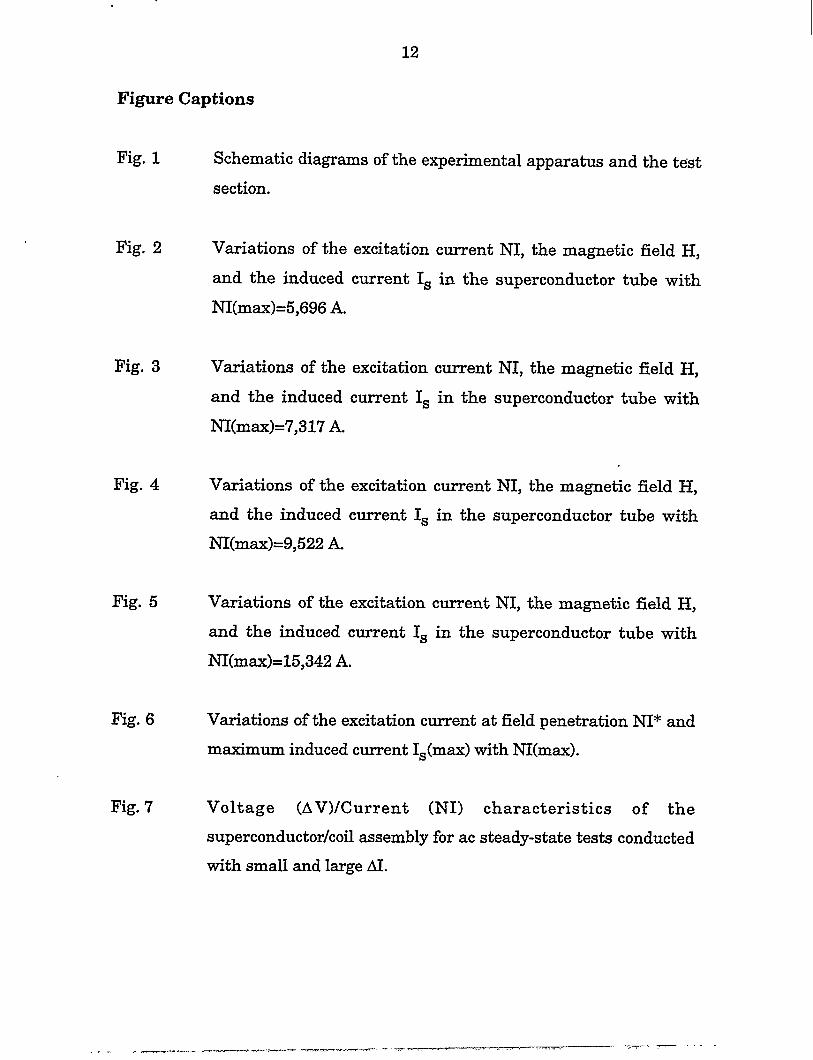
II. Experimental Apparatus
A schematic diagram of the test setup and the test section is shown in
Fig. 1. The test setup is identical to that reported previously by Cha and
Askew [13] whereas the test section is different. The major differences are (1)
the superconductor tube used in the present experiments is much larger than
that used by Cha and Askew, and (2) the number of turns of the copper coil
used in the present experiments is much smaller than that used by Cha and
Askew. The test section is made of a copper coil and a cylindrical
superconductor tube. The copper coil has 80 turns and is made of 6.6 mm by
2.2 mm flat copper wire. The copper coil is approximately 150 mm long and
has an inside diameter almost identical to that of the superconductor tube.
The large cross-sectional area of the copper wire kept the resistance of the
copper coil fairly low and reduces the amount of heating during the test and
superconductor is minimally tiected by the resistive heating in the copper
coil. The material of the superconductor tube was bulk Bi2Sr2CaCu20x and
was made born a melt-cast process. The BSCCO tube is 190 mm long with a
wall thickness of 8.0 mm and an outside diameter of 70 mm. A Hall probe is
placed near the center of the tube to measure the magnetic field in the hole of
the tube. A Rogowski coil is employed to measure the induced current in the
superconductor tube. The response times of both the Hall probe and the
Rogowski coil are much smaller than the transient time of the present
experiments [13]. The copper coil is comected to a pulsed current source
which is shown schematically in Fig. la. It consists of several capacitors in
parallel and an array of field effect transistors (FETs). .The capacitors are
charged by a high-voltage DC current source (lIVDC). The FETs are driven
by a fknction generator and the gates of the FETs can open and close in less
than a mini-second which is much shorter than the transient time of the
4
current experiments. Currently, the pulser can be operated up to a voltage of
200Volts.
Experimental Results
Figures 2 to 5 shows the measured excitation current NI, the magnetic
field H near the center of the superconductor tube, and the induced current Is
as a finction of time for four different magnitude of M in ascending order.
Figures 2 and 3 are for relative small values of NI while Figs. 4 and 5 are for
relatively large values of NI. In other words, NI in Figs. 4 and 5 rises faster
and to a larger value than that in Figs. 2 and 3. Figures 2 to 5 show that the
peak value of NI is reached at approximately 4.5 ms independent of the value
of NI(max). The rise time of the excitation current (or applied field) is
therefore 4.5 ms which equals approximately the rise time of a 60-Hertz ac
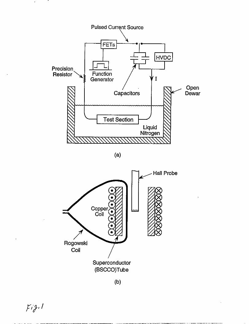
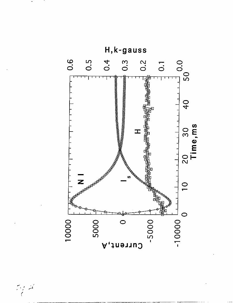
sinusoidal current. Figure 2 shows that for relatively small value of NI(max),
the applied field did not penetrate the superconductor tube and the magnetic
field (H) inside the hole of the tube was very small and remained constant.
The induced current (Is) was in the opposite direction of the excitation
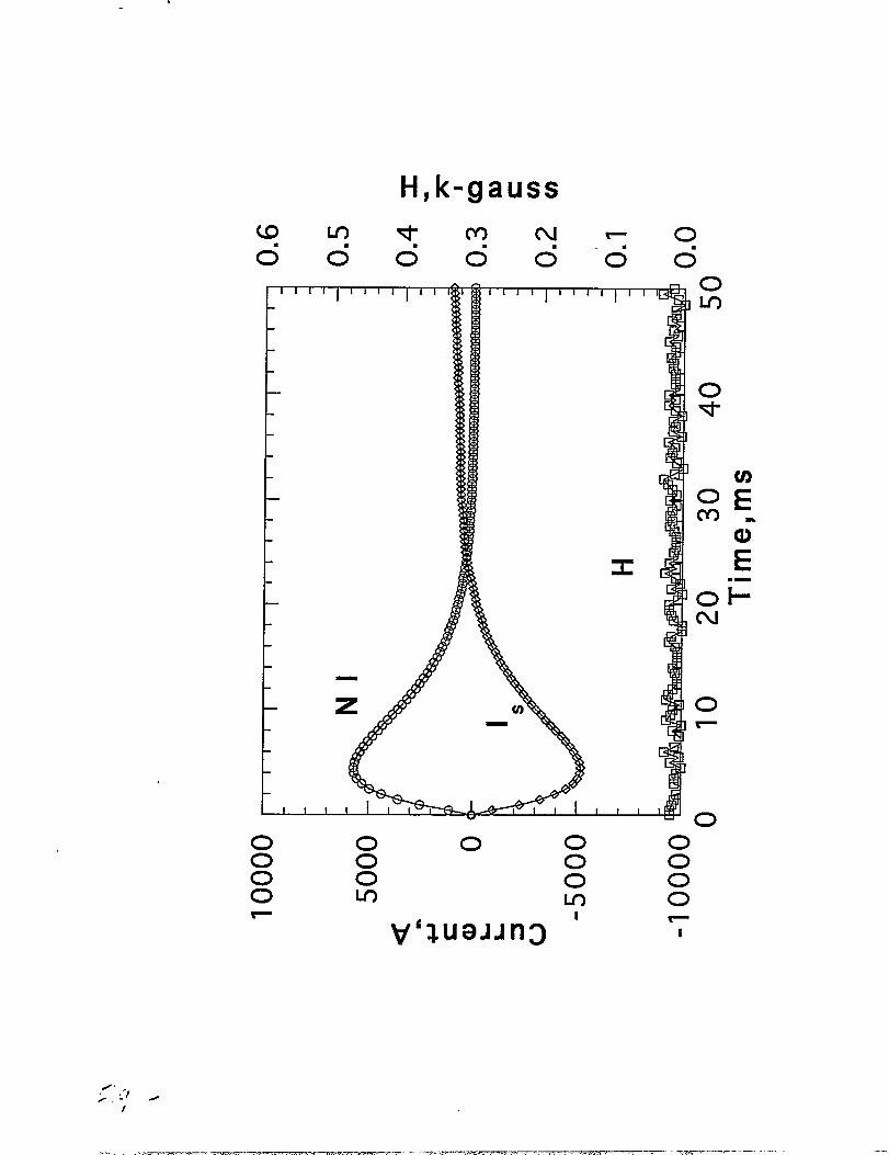
current (NI). Figure 3 shows that the magnetic field inside the hole of the
superconductor was constant initially and began to increase slightly after NI
reached its peak value and then remained fairly constant for a relatively long
period of time even though the excitation current was decreasing towards
zero. Field penetration of the thickness of the superconductor tube occurred
at 4.5 ms when both NI and Is reached its peak value and when H began to
increase slightly. The slight increase followed by the fairly constant value of
H after field penetration while NI was descending can be explained by the
concept of magnetic diffusion. Figure 4 shows similar result$when NI(max) is
increased, i.e., field penetration occurred at 4.5 ms when NI and Is reached
... . .—. ~— . ...— ---=...-.-. .-. ...... ------ --—- -, “---”
5
its peak value and H increased somewhat and remained fairly constant after
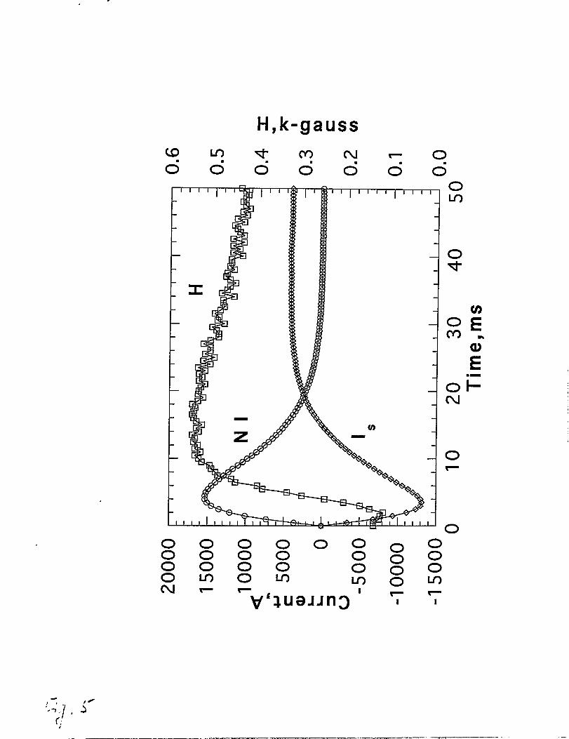
field penetration even though NI was decreasing. When NI(max) is increased
further as shown in Fig. 5, field penetration occurred at 3.0 ms slightly ahead
of the peak NI. After field penetration, H increased rapidly and reached its
maximum value at 12 ms. It can be clearly seen in Fig. 5 that peak H lags
peak NI. It should be mentioned that the induced current shown in Figs. 2 to
5 was always negative (relative to NI) initially and became positive near the
end (50 ms) to support a trapped field in the superconductor. Also, it should
be noted that the tests were conducted in increasing NI(max) without
warming up the superconductor tube between each test, therefore, there is
always a small trapped field inside the superconductor tube at the beginning
of each test [except for the first test at very small NI(max)]. This is why in
Figs. 2 to 5, H is always slightly positive at the beginning of the test.
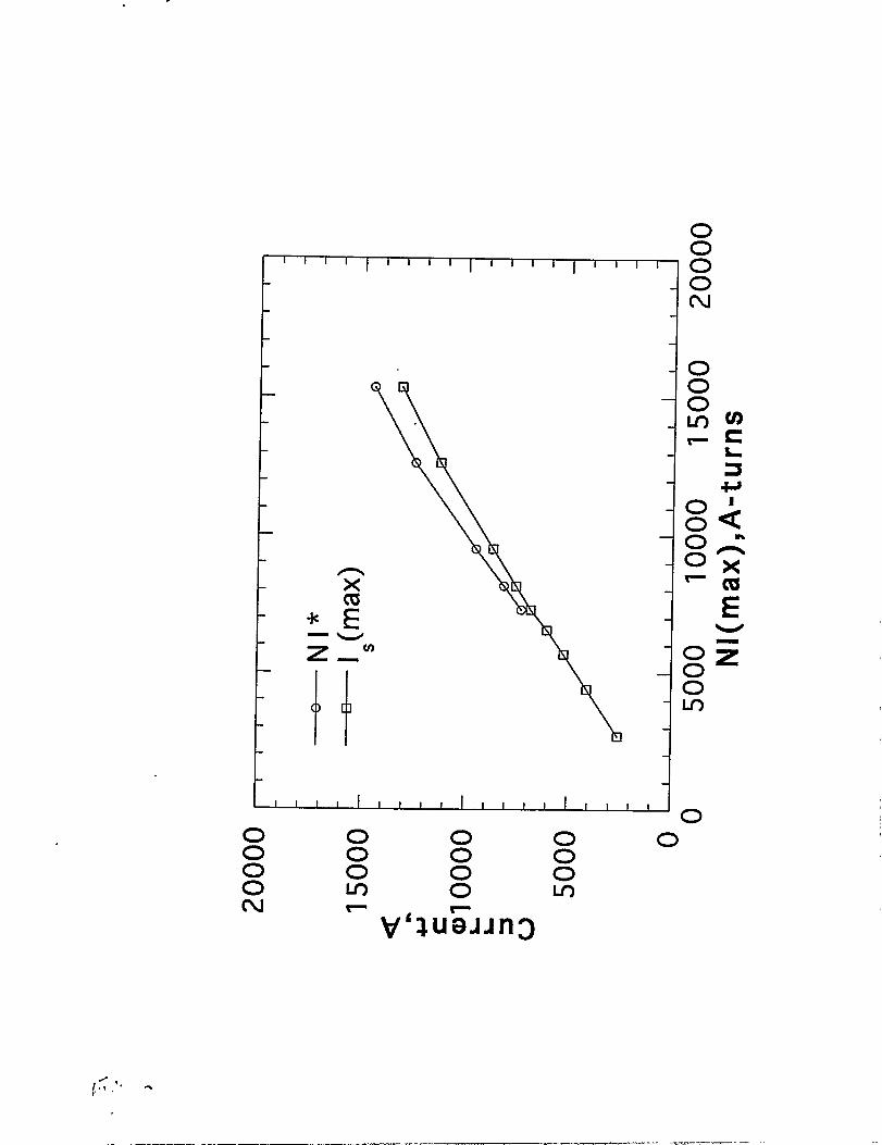
Figure 6 shows the plots of maximum induced current Is(max) and the
excitation NI at field penetration NI* versus M(max). NI* is determined
&om the profiles of H and NI. Specifically, NI* is the value of NI at the point
of field penetration which corresponds to the point where H begins to increase
in Figs. 3 to 5. Both NI* and Is(max) increase monotonically with NI(max).
For relatively small NI(max), magnetic flux density did not penetrate the
tube and NI* does not exist. NI* can be measured only when NI(max) is
increased to some minimum value when the applied field penetrates the tube.
Critical Current
Figure 6 shows that both the induced current and the excitation current
at field penetration increase monotonically with NI(max). This indicates that
there is no single (constant) value of NI* or Is(max) that can be assigned as
.
6
the critical current of the superconductor tube for the transient tests
described here. However, one of our objectives is to determine the ac steady-
state critical current of the superconductor tube by using the pulsed current
supply. The induced current Is(max) at the point where NI* first appears in
Fig. 6 may correspond to the ac steady-state critical current. This is also the
maximum induced current Is in Fig. 3 where M(ma) is increased enough so
that the magnetic flux just penetrated the tube. From Fig. 6, we found that
1~6,820 A. The critical current determined this way is the peak value.
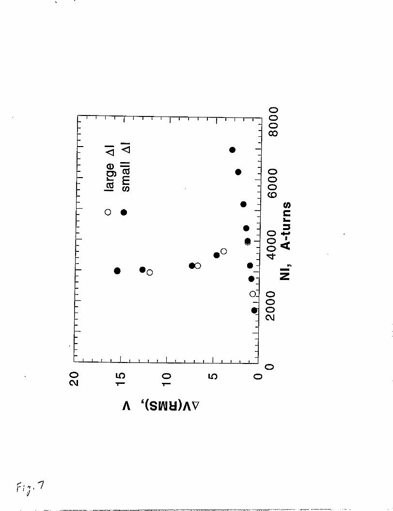
Therefore, IC(RMS)=4,823 A. To compare this critical current with the ac
steady-state critical current, we have measured the current/voltage
characteristics of the same coilhube assembly with an ac source at 60 Hz and
the results are shown in Fig. 7. Inside the superconductor tube, there is a
steel bar which forms an open core. These tests were conducted by
monotonically increasing the current through the copper at intervals. The
solid circles are the data for tests with relatively small increments of current
while the open circles are the data for relatively Iarge increments in current.
Before field penetration, the voltage rises linearly with current in Fig. 7. At
the point of field penetration the inductance of the coil jumps and it begins to
limit the current. This is shown as a rise in voltage and sharp decrease in
current in Fig. 7. Tests with small AI indicates that IC(RMS) is
approximately 7,000 A while tests with large AI give IC(RMS)4,000 A. Thus,
the ‘critical current measured by using the pulsed current supply
[IC(RMS)=4,823 Al is closer to the ac steady-state Ic with large AI than that
with small AI.
_.. -- ..-4.—.
_.— .—. ..—
7
Magnetic Difftwion
Under the magnetoquasistatic assumption, Maxwell equations can be
reduced to a magnetic difision equation [14]. For the present system with
cylindrical geometry, it can be shown that the following magnetic difision
equation applies
~[Dm(r ~B/&)]/i3r / r = ~Bfit, (1)
where the magnetic M?bsion coefficient Dm is
Dm = f)/f..@ (2)
and p is resistivity, ~ is permeability of free space, B is magnetic flux density
in the axial direction, r is the radial coordinate, and t is time. The magnetic
diffusion coefficient Dm is inside the derivative because the resistivity of the
superconductor is not uniform during the transient. This is the result of non-
uniform current distribution during the transient. The characteristic
diffusion time z is
T = a2/Dm
where a is the characteristic dimension of
2
the system. In the present
experiments, a is the thickness of the superconductor tube and equal to 8.0
mm. Magnetic diffusion arises because the characteristic diffusion time is
equal or larger than the characteristic time (the rise time) of the pulsed
system. As pointed out by Cha and Askew [13], the characteristic difision
time of the BSCCO-2212 tube is on the order of several hundred milli-
seconds, The rise time of the current pulse is only 4.5 ms. Therefore,
(3)
———-. — — —.. —. . ,— -— -. ——..
8
magnetic diffusion is important for the present experiments. Physically, this
means that NI is rising faster than the time required for the magnetic flux to
reach its steady-state value (Bean’s critical state model) and one must solve
the magnetic diffusion equation to obtain the correct magnetic flux density
distribution inside the superconductor tube during the transient. The reason
that H continues to increase while NI is decreasing, as shown in Figs. 3 to 5,
is the result of magnetic difision. Steady-state flux distribution does not
have time to develop and flux continues to diffise from the interior of the
superconductor towards both inner and outer surfaces of the superconductor
tube. The flux density at the inner radius continues to increase for sometime
while the applied field at the outer radius has already begun to descend.
Results similar to those shown in Fig. 6 were reported and explained (in
terms of magnetic difftmion) by Cha and Askew [13].
It should be emphasized that the flux creep/flux flow resistivity of the
BSCCO-2212 tube can change over several orders of magnitude during a
transient where the induced current changes born 500 to 2,000 A/cm2 [13].
This large variation in p will have significant impact on the characteristic
diffusion time and must be accounted for in the analysis. Work is in progress
in solving the non-linear diffusion equation (1) and the results will be
reported in the future.
The discussion so far has been limited to the case of constant
temperature in the superconductor tube. This assumption is valid provided
that dissipation and heat generation in the superconductor is small. As far
as NI(max) is relatively small, which is probably true for the present tests,
temperature variation in the superconductor can be neglected. However, in
practical applications where the fault current limiter is exposed to much
larger NI(max), heating (particularly near the outer radius of the
_., .—. —.. ---
9
superconductor tube) can be significant and equation (1) cannot be decoupled
from the heat transfer equations.
Summary and Conclusions
The transient response of a melt-cast-processed BSCCO-2212
superconductor tube is investigated by using a pulsed current source and a
copper coil wound externally to the tube. The induced current in the
superconductor tube is measured by a Rogowski coil. The penetration field is
measured by a Hall probe inside the hole of the tube. Experimental results
show (Fig. 6) that the maximum induced current Is(max) is not constant and
increases with maximum excitation current NI(max). Another experimental
observation is that there is a time delay between peak excitation current NI
and peak magnetic field H inside the hole of the superconductor tube (Fig. 5).
Both observations can be explained by magnetic difision in a conductor with
small but finite (flux-creep) resistivity. Magnetic difision arises because the
characteristic difision time for magnetic flux density is larger than the
characteristic time (the rise time) of the pulsed system. Consequently, there
is not enough time for the magnetic flux density to reach its steady-state
value (Bean’s critical state model) during the transient.
A critical current for the superconductor tube can be determined by
using the pulsed current system. This critical current is the induced current
in the superconductor tube at the point of field penetration when NI(max) is
increased just enough to penetrate the superconductor tube (Fig. 3). The
critical current determined this way is IC(RMS)=4,823 A. For comparison to
ac steady-state critical current, we also measured the voltage/current
characteristics of the superconductor tube. It was found that the ac steady-
—— ._.. ..== —m. . .,, ------- . . —.-.-3=-?=+=----====-=------ ---- ‘-~—. ‘ — - ‘“-
10
state critical current depends on the magnitude of AI used in the experiments
(Fig. 7). For relatively large AI, the ac steady-state critical current was
IC(RMS)S4,000 A which is in fair agreement with that measured by the
pulsed current system.
Acknowledgments
This work has been supported by the U.S. Department of Energy, Energy
Efficiency and Renewable Energy, as part of a program to develop electric
power technology, under Contract W-31-109-Eng-38.
References
1. T. Wakuda, T. Nakano, M. Iwakuma, K. Takeo, K. Yam~ji, Y. Yamada,
and S. Yasuhara, Cryogenics 37,381 (1997).
2. V. Plechacek, J. Hejtmanek, and V. Sims, IEEE Trans. on Applied
Superconductivity 7,2,703 (1997).
3. “F. Mrowka, M. Wurlitzer, P. Esquinazi, E. H. Brandt, M. Lorenz, and K.
Zimmer, Appl. Phys. Lett. 70,7,898 (1997).
4. E. V. Postrekhin, L. W. Zhou, K. J. Huang, C. B. Cai, S. M. Gong and Y.
X. Fu, Cryogenics 36,989 (1996).
5. V. Plechacek, E. Pollert, J. Hejtmanek, D. Semidubsky, and K. Knizek,
Physics C 225,361 (1994).
. ..- ..---”=,.,-, —— ~=,r-..”,. . ~,. ,, ,,. ,, , . . . . * . . . &-n————— —.—.——7%....
11
(5.
7.
8.
9.
10.
11.
12.
i3.
14.
B. W. lticketts, K.-H. Muller, and R. Driverj Physics C 183, 17 (1991).
V. Meerovich, V. Sokolovsky, G. Jung, and S. Goren, IEEE Trans. on
Applied Superconductivity, 5,2,1044 (1995).
D. W. A. Willen and J. R. Cave, IEEE Trans. on Applied
Superconductivity, 5,2,1047 (1995).
W. Paul, T. Baumann, and J. Rhyner, IEEE Trans. on Applied
Superconductivity, 5,2,1059 (1995).
M. Ichikawa and M. Okazaki, IEEE Trans. on. Applied
Superconductivity, 5,2,1067 (1995).
J. Acero, L. Garcia-Tabares, M. Bajko, J. Calero, X. Granados, X.
Obradors, and S. Pinol, IEEE Trans. on Applied Superconductive@, 5,2,
1071 (1995).
Y. S. Cha, Z. J. Yang, D. J. Evans, and J. R. Hull, Applied
Superconductivity 4,4,173 (1996).
Y. S. Cha and T. T. Askew, Physics C, 302,57-66,1998.
T. P. Orlando and K. A. Delin, Foundations
Superconductivity, Chapter 2, Addison-Wesley, 1991.
of Applied
— -——. .
12
Figure Captions
Fig. 1 Schematic diagrams of the experimental apparatus and the test
section.
Fig. 2 Variations of the excitation current NI, the magnetic field H,
and the induced current Is in the
NI(max)=5,696 A.
superconductor tube with
Fig. 3
Fig. 4
Fig. 5
Fig. 6
Fig. 7
Variations of the
and the induced
NI(max)=7,317 A.
Variations of the
and the induced
NI(max)=9,522 A.
Variations of the
excitation current NI, the magnetic field H,
current Is in the superconductor tube with
excitation current NI, the magnetic field H,
current Is in the superconductor tube with
excitation current NI, the magnetic field H,
and the induced current Is in the superconductor
NI(max)=15,342 A.
tube with
Variations of the excitation current at field penetration NI* and
maximum induced current Is(max) with M(max).
Voltage (AW/Current (NI) characteristics
superconductor/coil assembly for ac steady-state tests
with small and large AI.
of the
conducted
.. . . --—=. ---.——-- ~- ..— . -“------------ - -- ----- ., ~.. -=---- . -._.r ------
PrecisionResistor >
Pulsed Current Source
\
-P--II
JAl-L- ~ HVDC
7+”’Function
Generator
/.Capacitors
Test Section
(a)
Coil/
Superconductor
(BSCCO)Tube
(b)
OpenDewar
—— .—.. -——— —.—— . —---- .,.. . . . .
H,k-gauss
@md-mmJr o0000
0000F
000I i I i 1 “’’1” o
In
a)
E.-of-N
0F
nw
0 0 0 0
0 0 00 0 0m o
-. .. —..———————.———-...—. —— -------- ..—. — -. -w.m_.,——._ ..
H,k-gauss
Qm*mmJ. o000000 0
n
l–1-0
ls-
C/a0m E
aE
1 I ● -
0N
0~1-
I I I I I l-1~ I I I I l-ml 1 00 0 0 0 00 0 0 00 0 0 00 In In 0
f-
q ,’ , >
(
....-.. . .,—s. — .-. --....,-—. ?- .—,-.-> . . . . ,.24..—-. -, -.. -. . . . . . . . . . = . ,.,. ..,. -.-—— -- --- . .——.———— . .
H,k-gauss
(Qmq-
000mmlr-o
0000I I I I 1“”1’
r
0 00 00 00 In
0 0 00 00 0m 0
coEa“E
OgN
o
—— —— —.-. -. ---- . .
H,k-gauss
u) *
000[ I I I l“
n
l“
tt-w
mo-r
N F o000
1 II“’’l ’”il
--l
lllldll m%%-1--&Ua-@RTihJ
o000N
o000
0000 0g o
m
o000F
1
000Inr
1
0m
o
!..,/
-/ J.-1. ,
f;
..
0
0000N
oI I I I
I1 I I I
II I 1 I
II I I I o
0
I 1 I I I I I I I I I I I I I 1 I I I‘o
im
000m
o
.— —..—.——-.
00
● ●0
I I I [ I I I I I I I I I I I I I I I
7
●
●
tlflll, ,, 11, ,,11, ,,,fl
A ‘(SUW)AV
m o
co
d-
N
0
-.. ——. — ———.— . . .. —-—. —. -.—. -——— .-


![EMC of harmonic and transient measurement equipment in ...orbit.dtu.dk/files/6489397/prod11326808732141.EGYPRO_EMC_final[1].… · EMC of harmonic and transient measurement equipment](https://img.pdfslide.us/doc/110x75/5b70b2587f8b9a66338d9744/emc-of-harmonic-and-transient-measurement-equipment-in-orbitdtudkfiles6489397.jpg)