Embed Size (px)
Citation preview

Experiment (9)
Measure the Distance Between Tracks of
CD and DVD The aim of work:
1-measure the distance between tracks of CD and DVD.
2-study the different between the CD & DVD.
Instruments:-
Laser He-Ne, CD & DVD, screen, ruler, holders
Theory:-
The Compact Disc was invented by Sony and Philips in 1981 in order to serve as a
high-quality compact audio storage device which allowed for direct access to digital sound
tracks. It was officially launched in October 1982. In 1984, the Compact Disc's
specifications were extended (with the publication of the Yellow Book) so that it could store
digital data.
A CD (Compact Disc) is an optical disc 12cm in diameter and 1.2mm thick (its
thickness may vary from 1.1 to 1.5 mm) for storing digital information: up to 650 MB of
computer data (equivalent to 300,000 typed pages) or 74 minutes of audio data. A circular
hole 15mm in diameter is used to centre it on the CD player's surface.
A CD is built from a plastic (polycarbonate) substrate and a fine, reflective metallic
film (24-carat gold or a silver alloy). The reflective layer is then covered with an anti-UV
acrylic finish, creating a protective surface for data. Finally, an additional layer may be
added so that data can be written on the other side of the CD as well.
University of Technology
Laser & Optoelectronics Engineering Department
Laser Eng Branch
Laser application Lab.
The reflective layer contains tiny bumps. When the laser passes over the
polycarbonate substrate, light is reflected off the reflective surface, but when the laser
reaches a bump, that's what allows it to encode information. This information is stored in
22188 tracks engraved in grooves (though it's actually just one track spiralling inward).
Commercially purchased CDs have already been pressed, meaning that the bumps
have been created used plastic injected into a mold which contains the desired pattern in
reverse. A metallic layer is then affixed onto the polycarbonate substrate, and this layer is
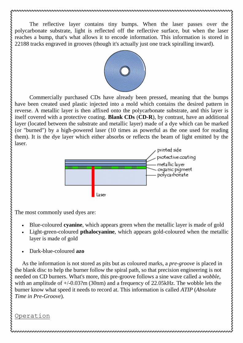
itself covered with a protective coating. Blank CDs (CD-R), by contrast, have an additional
layer (located between the substrate and metallic layer) made of a dye which can be marked
(or "burned") by a high-powered laser (10 times as powerful as the one used for reading
them). It is the dye layer which either absorbs or reflects the beam of light emitted by the
laser.
The most commonly used dyes are:
Blue-coloured cyanine, which appears green when the metallic layer is made of gold
Light-green-coloured pthalocyanine, which appears gold-coloured when the metallic
layer is made of gold
Dark-blue-coloured azo
As the information is not stored as pits but as coloured marks, a pre-groove is placed in
the blank disc to help the burner follow the spiral path, so that precision engineering is not
needed on CD burners. What's more, this pre-groove follows a sine wave called a wobble,
with an amplitude of +/-0.03?m (30nm) and a frequency of 22.05kHz. The wobble lets the
burner know what speed it needs to record at. This information is called ATIP (Absolute
Time in Pre-Groove).
Operation

The read head is made of a laser (Light Amplification by Stimulated Emission of
Radiation) which emits a beam of light, and a photoelectric cell which captures the reflected
beam. CD players use an infrared laser (with a wavelength of 780 nm), as it is compact and
inexpensive. A lens located near the CD focuses the laser beam onto the pits. A semi-
reflective mirror allows the reflected light to strike the photoelectric cell, as shown in the
following diagram:
A "pickup" moves the mirror so that the read head can access the entire CD-ROM.
A CD has two basic operating modes:
Encoding information
The physical track is made up of bumps 0.168?m deep and 0.67?m wide, with variable
length. The "rings" in the spiral are spread about 1.6?m apart from one another. Pits are the
.
The laser used for reading CDs has a wavelength of 780 nm when travelling through
air. As the polycarbonate's refractive index is 1.55, the laser's wavelength in the
polycarbonate is equal to 780/1.55 = 503nm = 0.5?m. Since the depth of the groove is one
term for the depressions in the groove, and lands are the spaces between them

quarter the wavelength of the laser beam, a light wave reflected by a pit travels half again as
long (125% as long to hit the disk and the same to return) as a wave reflects by a land. This
way, whenever the laser strikes a pitted groove, the wave and its reflection are dephased by a
half wavelength and cancel one another out (destructive interference), so it's as if no light
was reflected at all. Moving from a pit to a land causes a drop in the signal, which represents
one bit. The length of the groove is what stores the information. The size of a bit on a CD
("S") is standardized and corresponds to the distance travelled by the light beam in 231.4
nanoseconds, or 0.278?m and the standard minimum velocity of 1.2 m/s. In the EFM
standard (Eight-to-Fourteen Modulation), used for storing information on a CD, there must
always be at least two bits set to 0 between two consecutive 1 bits, and there cannot be more
than 10 consecutive zero bits between two 1 bits, in order to avoid errors. This is why the
length of a groove (or a land) is greater than or equal to the length needed to store the value
OO1 (3S, or 0.833?m) and less than or equal to the length of the value 00000000001 (11S, or
3.054?m).
DVD Digital Versatile Disk
In 1995, new standard was established for DVD Digital Versatile Disk (called at first
Digital Video Disk). They were first developed for storing a full digital movie. The DVD is a
special disk that can store up to 4.7 GB information on a single layer on the disk. The new
devices can store information on both sides, so the total amount of information is 9.4 GB.
The size of the DVD is the same as CD, but because it use a shorter wavelength, the pits
can be smaller (minimum size 0.4 µm) and so is the distance between tracks (0.74 µm).
CD-ROMs are based on Diode laser with Infra-Red wavelength of 780 nm.
DVD devices are based on Diode laser with red wavelength of 650 nm. As we saw, the
exact wavelength is a critical parameter in reading the information, since the process is based
on the interference between the beams reflected from different depths inside the recording
media.
In order for the new DVD machines to be able to read CD-ROM media, two separate
optical pickups need to be inside. Each Optical pickup operates at its own specific
wavelengths.
DVD increases its capacity by using higher resolution optics. DVD uses a shorter
wavelength laser with red light around 650 nm compared to a CD with infrared light at 780
nm. In addition, better focusing optics allows closer tracks and smaller pits; as shown in the
diagrams below

Procedure:
A. First method :-determine the spacing between tracks by using the concept of
diffraction
1. Set up the laser, CD and a sheet of paper as shown.
2. Put the CD in a 45 degree angle.
3. you should see a bright spot on the paper directly underneath the CD along
with other
diffraction spots in line with the laser.
4. Determine the position of each spot on the paper.
5. Measure the
L = Distance of laser beam above paper
w = Distance between diffraction spots
A red laser light has a wavelength of about
λ = 650 nanometers (6.5 ×10⁻⁷ meters).
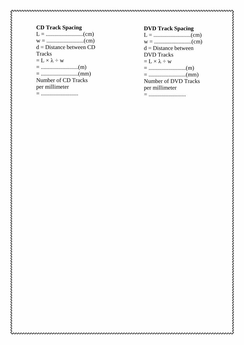
CD Track Spacing
L = ..........................(cm)
w = ..........................(cm)
d = Distance between CD
Tracks
= L × λ ÷ w
= ..........................(m)
= ..........................(mm)
Number of CD Tracks
per millimeter
= ..........................
DVD Track Spacing
L = ..........................(cm)
w = ..........................(cm)
d = Distance between
DVD Tracks
= L × λ ÷ w
= ..........................(m)
= ..........................(mm)
Number of DVD Tracks
per millimeter
= ..........................

-the spacing between tracks Geometrically: determine -method: second. A
1. Vertical Geometry:-
A. Put the CD or DVD vertically as shown in figure ,where the grating equation is
B. If we let the distance from the grating to the wall be L and the distances of the
zeroth and n the order diffraction spots from the horizontal plane to beY0 and Yn
respectively, then
You could think about aligning the laser beam normal to the diffraction grating. Then oθ=0
and the grating equation simplifies to
Fig. 1 Geometry for Eq. (1). The zeroth order
diffraction (n=0) at θ0 is basically a simple
reflected beam. Note that the sketch assumes
the CD is parallel to the wall.

Horizontal Geometry -2
The CD flat can be placed horizontally on the holder provided. This geometry is
pictured in Fig. 1 of The compact disk as a diffraction grating. Be careful to label your
angles correctly. In the grating equation, θ is the angle between the normal to the disk and
the laser beam, but you will likely make your measurements relative to the plane of the disk,
say φ, so that cosФ=sinθ.
From Fig. 2 it is seen that and for n=1,

Discussion:
1.from any material the CD & DVD manufactured ?
2.Why DVD-ROM can read CD & DVD ? and why CD-ROM read only CD?
3.What is the best method, diffraction or geometrical ?Why?
4.is the lens that found in CD or DVD –ROM moving or standing ?Why?
5.Explaine Blu-Ray technique ?
6. what is the advantage of beam splitter in CD-ROM or DVD-ROM?