Embed Size (px)
Citation preview

011/9664616

MPCT20 M1 mect s.r.l.
ME3007_10 03/10 2
MPCT20 M1 mect s.r.l.
ME3007_10 03/10 3
INDEX
INDEX........................................................................................................................... 3
1.0 OVERVIEW................................................................................................... 5
1.1 TECHNICAL FEATURES .................................................................................. 5
1.2 DISPLAY MESSAGES ....................................................................................... 6
1.3 WIRING DIAGRAMS......................................................................................... 6
1.4 WIRING SCHEMATICS FOR COUNTER, FREQUENCY METER
REVOLUTION COUNTER AND HOURLY PRODUCTION ................................ 7
1.5 WIRING SCHEMATICS FOR TIMER............................................................... 8
1.6 PROGRAMMING TIPS ...................................................................................... 9
1.7 RPM, FREQ. OR PR.H INSTRUMENT MENU FLOW.................................. 10
1.8 COUNTER INSTRUMENT MENU FLOW ..................................................... 11
1.9 TIMER INSTRUMENT MENU FLOW............................................................ 12
1.10 PRINTED CIRCUIT BOARD (PCB) CONFIGURATION............................ 13
2.0 REVOLUTION COUNTER, FREQUENCY METER AND HOURLY
PRODUCTION INSTALLATION REMARKS......................................................... 13
2.1 INSTALLATION PROCEDURE ...................................................................... 13
2.2 "nUn" and “dEno” FUNCTION......................................................................... 16
2.3 EXPLICATIVE EXAMPLES............................................................................ 16
2.4 DEFAULT PARAMETERS (dEF) .................................................................... 17
3.0 PEAK-HOLD (PICC) FUNCTION ............................................................. 18
4.0 “FILTER” FUNCTION .............................................................................. 19
5.0 REVOLUTION COUNTER, FREQUENCY METER AND HOURLY
PRODUCTION ALARMS.......................................................................................... 20
5.1 ALARM SETTING............................................................................................ 21
6.0 PULSE COUNTER INSTALLATION NOTES ......................................... 23
6.1 INSTALLATION PROCEDURE.................................................................... 23
6.2 UP-DOWN FUNCTION and TERMINAL CONFIGURATION .................... 27
7.0 PULSE COUNTER AND TIMER ALARMS ........................................... 28
7.1 “UP” COUNT MODE ALARMS ..................................................................... 28
7.2 “DOWN” COUNT MODE ALARMS............................................................... 28
8.0 TIMER INSTALLATION NOTES............................................................. 30
9.0 PASSWORD FUNCTION.......................................................................... 33

MPCT20 M1 mect s.r.l.
ME3007_10 03/10 4
10.0 SET UPS ................................................................................................... 35
! 11.0 NOTES ...................................................................................................... 35

MPCT20 M1 mect s.r.l.
ME3007_10 03/10 5
1.0 OVERVIEW
The MPCT20 M1 model has 5 main programmable functions: RPM meter, frequency
meter, hourly production meter, timer, and uni-directional pulse counter.
Each one of these five functions is independent.
The instruments have two relay alarms.
Main characteristics are:
• count memory for almost ten years (yuo can exclude this function fron the menu)
• five digits for counting and five digits for Set-Point.
• NPN or PNP inputs (open collector or passive pull-up) or not amplified proximity
(configured by jumpers or terminal connections)
• two contact relay alarm outputs (5A switch) or only one exchange relay ( SR1F
option )
• programmable multiply factor from 1 to 65535
• programmable divide factor from 1 to 65535
• programmable pre-set (pulse counter and timer only)
• up/down count (pulse counter and timer only)
• visualisation of the partial or total counting ( counter only )
• timer ( hold and reset ) or chronometer ( start, stop, reset ) functioning
• working-break functioning (timer)
1.1 TECHNICAL FEATURES
Table 1
Inputs uni-directional npn/pnp encoder
3 wire npn/pnp amplified proximity
2 wire not amplified proximity
mechanical switch
IBT (option)
Transducer supply 16 Vdc / 50 mA not reg..
Digits max inputs 99999
Frequency max. (RPM) 2 KHz
Frequency min. (RPM) 0.001 Hz
Min. width pulse 500 µs
Notches number 1 to 9999
Divider 1 to 65535
Multiplier 1 to 65535
RPM meter max error 0,01 %
Timer max error 0.01 %
Alarm output 2 contact relay 5A/250 Vac
exchange relay 5 A/250 Vac ( SR1F option )
Supply 12÷30 Vdc

MPCT20 M1 mect s.r.l.
ME3007_10 03/10 6
25 Vac/50 ÷ 60 Hz
115 Vac/50 ÷ 60 Hz
230 Vac/50 ÷ 60 Hz
Dimensions 48 x 48 x 96 mm
Piercing template 45 mm (height) x 45 mm (width)
1.2 DISPLAY MESSAGES
Table 2
n000.0 r.01.00 S W release
-OFL- overflow
-UFL- underflow
Err error in programming parameter
1.3 WIRING DIAGRAMS
DESCRIPTION OF THE FRONT COMMANDS
Upper Display: count display
Lower Display: set-point or total count display
Led AL1: alarm 1 status indication
Led AL2: alarm 2 status indication
Key : access to the programming functions
Key : Alarm 1 key (can be disabled) / program key
Key : Alarm 2 key (can be disabled) / program key
Key : Clear count (can be disabled) / fast exit in menu

MPCT20 M1 mect s.r.l.
ME3007_10 03/10 7
BASIC TERMINAL BOARD DESCRIPTION
Terminal 1 - pull-up resistor for terminal 2
Terminal 2 - counting input or “start” for timer in chronometer function
Terminal 3 - external reset / Up-Down counting selection
Terminal 4 - “hold” or “stop” for timer / Up- Down counting selection
Terminal 5 - ground
Terminal 6 - transducer power supply (16Vdc)
Terminals 7, 8 - instrument power supply (if power supply “Vcc”: 7 = Vcc;
8 = gnd)
Terminals 9, 10 - contact relay output (AL1)
Terminals 9, 10, 11 - exchange relay output ( if option: SR1F 9 = Com, 10 =
N.O., 11 = N.C.)
Terminals 11-12 - contact relay output (AL2)
If STN2 options, see “static outputs connection”
1.4 WIRING SCHEMATICS FOR COUNTER, FREQUENCY METER REVOLUTION COUNTER AND HOURLY PRODUCTION
Prox npn connection Prox pnp connection

MPCT20 M1 mect s.r.l.
ME3007_10 03/10 8
+
-
Magnetic pick-up (IBT option) connection
1.5 WIRING SCHEMATICS FOR TIMER
+
-
+
-
+
-
sta
rtst
op
rese
t
for input resetand stop PNPsee "Print circuitboard configuration"
Not amplified MAF 35 sensor
connection (maf 35)
MECHANICAL contact connection (
It’s necessary to make an internal link.
See “Printed circuit board
configuration” )
For frequency generator
connection use 2 (+) and 5 (-)
terminals
Prox npn connection Prox pnp connection

MPCT20 M1 mect s.r.l.
ME3007_10 03/10 9
Switch connection
start
stop
reset
Static outputs connection
9 = out AL 112 = out AL 2
10, 11=Gnd
1.6 PROGRAMMING TIPS
• Search for the item to change, shown in the upper display using key .
The value to change is shown on the lower display.
• If you want to change a number, use the key to increment the blinking
digit, and the key to shift the blinking digit, and if you want to select an
item, use the key. In either case use the key to confirm the input
and go to the menù.
• To exit the menù, press : the modified parameters will be stored

MPCT20 M1 mect s.r.l.
ME3007_10 03/10 10
1.7 RPM, FREQ. OR PR.H INSTRUMENT MENU FLOW
Notes:
The symbol means:
The symbol means:
see “revolution counter,
frequency meter and hourly
production alarms”
see “filter
function ”
see “revolution counter,
frequency meter and
hourly production
installation remarks”
see “nUn and dEnO”
function
see “peak hold
function”
Measure

MPCT20 M1 mect s.r.l.
ME3007_10 03/10 11
1.8 COUNTER INSTRUMENT MENU FLOW
Notes:
The symbol means:
The symbol means:
see “pulse counter
installation notes”
Total counting zero
setting if
“d.InF=tot”
see “nUn and dEnO”
function
see “pulse counter and
time alarms”

MPCT20 M1 mect s.r.l.
ME3007_10 03/10 12
1.9 TIMER INSTRUMENT MENU FLOW
Notes:
The symbol means:
The symbol means:
see “timer installation
notes”
Set the right
code for
requested scale
see “pulse counter and
timer alarms”

MPCT20 M1 mect s.r.l.
ME3007_10 03/10 13
1.10 PRINTED CIRCUIT BOARD (PCB) CONFIGURATION
Open the instrument to configure the main input (standard or mechanical contact)
and the “Hold” and “Reset” (NPN and PNP) inputs. To open the instrument use a
screw-driver to take off the back of the body of the instrument and extract the
instrument from the back.
To set up the input circuit as mechanical contact link by the jumper the JP1
configuration.
To set up the “Reset” and “Hold” inputs as PNP version, move the JP4 and JP5
jumpers in 1-2 position.
JP1
JP4 JP5
1
2
2.0 REVOLUTION COUNTER, FREQUENCY METER AND HOURLY
PRODUCTION INSTALLATION REMARKS
2.1 INSTALLATION PROCEDURE
1) Make connections as indicated at pages: 7, 8 and 9
HOLD terminal connections:
when it works, it stops the visualization and the acquisition of new input signals.
To modify the “hold” input for a PNP input look paragraph “PCB configuration”
2) Switch the unit on.
3) Program the functions based on the indications in the following table:
Table 3
n°
seq.
Press
Key
Upper
display
Lower
display
Remarks
1 enter Touch the “enter” key
2 enter PASS 0 000 In this phase the instrument asks for the of

MPCT20 M1 mect s.r.l.
ME3007_10 03/10 14
n°
seq.
Press
Key
Upper
display
Lower
display
Remarks
“password” number to protect the data
programmation (see “Password functon”)
3 SEL Ou
4 AL15 SEL InP
5 AL15 SEL CPAS
6 AL15 SEL dEF
7 AL15 SEL tYPE TYPE INSTRUMENT
8 enter tYPE rPn rPn = rpm meter
Pr.h = hourly production meter
FrEq = frequency meter
CSEC = timer
CIn = counter
Select by “AL15 “key “rPn” to program
revolution counter, or “FrEq” to program
frequency meter or “Pr.h” to program hourly
production. (Confirm by “enter”)
9 SEL tYPE
10 Reset
Exit
“misura” SP 1
4) Program the functions of the following table to set notches number (n.rIF),
multiplaying or division Factors (uUn or dEnO) and the decimal point.
5) Set up, if requested, the peak function; for this function in detail see “peak-
hold function” paragraph.
6) Set up, if necessary, a digital filter (menu item “nFIL”, dEL and PEr). For
these functions in detail see “filter function” paragraph.
7) For default parameters see "default parameters" paragraph
8) Set alarms
9) Set, if desired, the programming menu access code (password function)
10)The unit is now ready to be used.
Table 4
n°°°°seq. Press
Key
Upper
display
Lower
display
Remarks
1 Enter Touch the “enter” key
2 Enter PASS 0 000 In this phase the instrument asks for the of
“password” number to protect the data
programmation (see “Password functon”)
3 SEL Ou
4 AL15 SEL InP

MPCT20 M1 mect s.r.l.
ME3007_10 03/10 15
n°°°°seq. Press
Key
Upper
display
Lower
display
Remarks
5 enter InP FIL DIGITAL FILTER PROGRAMMING (look
paragraph)
6 AL15 InP n.rIF NOTCHES NUMBER
7 enter n.rIF 00001 set number of notches requested (1÷9999)
**(press “enter” to confirm)
8 InP n.rIF
9 AL15 InP P.dEC DECIMAL POINT
10 enter P.dEC 0.0000 Press key "4" until the decimal point is
displayed at the desired position.
**(press “enter” to confirm)
11 InP P.dEC
12 AL15 InP nUn MULTIPLY FACTOR
13 enter nUn 10000 Set multiplying factor value (see “nUn and
dEno function”) ** (press “enter” to confirm)
14 InP nUn
15 AL15 InP dEno DIVISION FACTOR
16 enter dEno 10000 Set division factor value; (see “nUn and dEno
function”); **(press “enter” to confirm)
17 InP dEno
18 AL15 InP PICC PEAK SET-UP
19 enter PICC P.OFF P.OFF = Peak excluded
P.h.O = Maximum peak with time
P.h.I = Maximum infinite peak
P.L.O. = Minimum peak with time
P.L.I = Minimum infinite peak
Touch “AL15” key until there appears the
req. item (confirm to “enter”)
20 InP PICC
21 AL15 InP .HLd TIME OF READING RETENTION
22 enter .HLd 25.0 write retention time (0 ÷ 25.0 sec) if PhO or
PLO is req. ** (confirm to “enter”)
23 InP .HLd
24 Reset
Exit
“measure
”
SP 1
** see para. “SET-UPS” to change the set value.

MPCT20 M1 mect s.r.l.
ME3007_10 03/10 16
2.2 "nUn" and “dEno” FUNCTION
There are two menu items that allow to modify the displayed value by a constant
factor. The “nUn” item allows to program a multiply factor in the range 1 ÷65535,
and the “dEno” item allows to program a divide factor in the range 1 ÷65535.
The constant factor will be:
nUn
readout on the display = _________ * X
dEno
Where:
X = “RPM measured” if the instrument is set up in revolution counter
X = “Pr.h measured” if the instrument is set up in hourly production
X = “pulses read at the input” if the instrument is set up in pulse counter
For a reading without correction factors is sufficient to set up nUn = dEno, instead to
add corrective costants is necessary to set up “nUn” and “dEno” to get the desired
value.
The visualization in RPN and Pr.h are linked by the following connections:
60 * Hz nUn
RPM (rPn) = ____________ * _________
n.riF dEno
3600*Hz nUn
Pr.h = _____________ * ____________
n.riF dEno
(Hz = frequency at the instrument input)
2.3 EXPLICATIVE EXAMPLES
• Make following settings on “rev. counter” instrument.
The parameter to be measured is the speed, in mt/sec., of toothed belt by reading the
rotating speed of the driving shaft. Four notches can be identified on the shaft and
the belt advances by 0.55 mt for one revolution of the shaft.
To get the requested visualisation, you have to multiply the reading
revolution/minute (RPM) by 0.55. To visualize the revolution/minute reading you
must set up in the menu item “n.riF” = 4 (notches for revolution). To correct the
visualisation by a 0.55 factor, you have to set up “nUn” = 55 and “dEno” = 100.
Infact we know this relation:
nUn 55
reading = RPM * _______ = RPM * _____ = RPM * 0.55
dEno 100
The unit can be programmed whit:
selection “rPn”

MPCT20 M1 mect s.r.l.
ME3007_10 03/10 17
n. rIF = 4
nUn = 55
dEno = 100
• Make following setting on “hourly production” instrument.
The parameter to be measured is the hourly production of a toothed belt moving
bottles. Each toothed represent a row of ten bottles.
To get the requested visualisation, you have to multiply 10 with the hourly
production meter reading (Pr.h). To visualize the hourly production meter reading
you must set up in the menu item “n.riF” = 1 (notches for revolution). To correct the
visualisation by a 10 increasing factor, you have to set up “nUn” = 10 and “dEno” =
1. Infact we know this relation:
nUn 10
reading = Pr.h * _______ = Pr.h * _____ = Pr.h * 10
dEno 1
The unit can be programmed with:
selection “Pr.h”
n. rIF = 1
nUn = 10
dEno = 1
2.4 DEFAULT PARAMETERS (dEF)
Some wrong values in menu programming function can cause the “ERR” item to
appear. To reset to factory default parameters you can use the DEF function, which
sets up all the programmation parameters at the factory value, eliminating all the
error situation (look the following table).
BE CAREFUL: all previous programmed values will be lost.
Table 5
n°
seq.
touch
key
upper
display
lower
display
NOTES
1 enter Touch the “enter” key
2 enter PASS 0 000 Digit the personal password
** (confirm with “enter”)
3 SEL Ou
4 AL15 SEL InP
5 AL15 SEL C.PAS
6 AL15 SEL dEF DEFAULT PARAMETERS
7 enter dEF On Touch the " AL15" key until the written
“ON” appears ** (confirm with “enter”)
The instrument exits from the programming
menu and it executes an automatic power on.

MPCT20 M1 mect s.r.l.
ME3007_10 03/10 18
3.0 PEAK-HOLD (PICC) FUNCTION
By using the “PICC” function it is possible to memorize the highest (P.h.) or the
lowest (P.L.) readings leaving them continuously on the display (P.h.I. - P.L.I.) or
just for a pre-set time limit from 0 ÷ 19.9 sec using the “hld” function (P.h.O. -
P.L.O.) . This function, if unwanted, can be excluded from the programming or by
short-circuiting hold terminals.
The following two examples describe the main operating methods of the “PICC”
function, while for the complete programming please refer to TAB 3.
• EXAMPLE 1
Programme with the function "PICC" the "P.h.0." item.
and in the "HLd" function the time "10.0" sec.
The instrument thus programmed, will follow the entry signal only in the
variations that increase the reading value, while, for decreasing readings, the
instrument maintains the fixed display for 10 seconds, after which the correct value
will appear. Of course during this 10 second period the instrument detects an
increase in the reading value, the display becomes updated and the time zeroed. (See
fig 1).
The “PICC” function can be excluded by short-circuiting the terminals 5 and 4.
• EXAMPLE 2
Programme with the function "PICC" the "P.h.I." item.
The instrument behaves exactly in the same way as the one described before with
the variation that the time is not programmable but fixed up to an infinite value. Also
in this case the cancellation of the peak memorisation and the exclusion of that
function can be undertaken by short-circuiting terminals 5 and 4.
lettura
ingresso
Fig. 1

MPCT20 M1 mect s.r.l.
ME3007_10 03/10 19
4.0 “FILTER” FUNCTION
The MPCT20 M1 serie instruments provide the following filtering mode:
1. n.FIL : number of averages of the converted value (it acts within the window
called “del”)
2. dEL : window within which the averages are taken (the number of averages taken
is as programmed at item “n.FIL”). At the displayed number, a window (dEL) is
calculated, all numbers courted within this window are averaged, whereas those
exceeding the window immediately update the display.
3. PEr : time in seconds by which the last averaged value is shown.
When the converted value exceeds the set window value programmed in the dEL
item, the dwell time (Per) gets started. If after the dwell time (Per) the converted
value falls again within the set windows value, the old value is not considered for the
average, otherwise the display is immediately updated.
dEL
dEL
PEr PEr
display value
converted value
Fig. 2
To program these items follow the instructions in the following table.
Table 6
n°
seq.
touch
key
upper
display
lower
display
NOTES
1 enter Touch the “enter” key
2 enter PASS 0 000 Digit personal password code
(look “Password function”)
3 enter SEL Ou
4 AL15 SEL InP
5 enter InP FIL FILTER PROGRAMMING
6 enter FIL n.FIL NUMBER OF AVERAGES
7 enter n.FIL 128 Press key “AL15 “ until the display shows the
number of averages required (o= no filter).

MPCT20 M1 mect s.r.l.
ME3007_10 03/10 20
n°
seq.
touch
key
upper
display
lower
display
NOTES
**(press “enter” to confirm)
8 FIL n.FIL
9 AL15 FIL dEL FILTERING WINDOW
10 enter dEL 250 Set the number of digits within the filter is
activated. **(press “enter” to confirm)
11 FIL dEL
12 AL15 FIL PEr Dwell time
13 enter PEr 2.50 write retention time (0.01÷2.50 sec)
**(press “enter” to confirm)
14 FIL PEr
15 Reset
Exit
Measure SET 1 Procedure to exit programming mode
** see “SETTING” paragraph to change the set value.
5.0 REVOLUTION COUNTER, FREQUENCY METER AND HOURLY
PRODUCTION ALARMS
The MPCT20 M1 serie instruments have two relay or static alarms and they can have
an exchange relay ( if requested SR1F option ) and the following voices can be
programmed:
1) Hysteresis from 1 to 250 digits
2) Delay time from 0 to 250 seconds, with the following configurations:
• activation delay
• de-activation delay
• activation and de-activation delay
3) Activation at max or min level
4) Window activation; max or min level can be set
Programming of the above functions is described here below in more detail.
a) SP1 : Setting of alarm threshold in the range 0÷99999
In the case of window type threshold “SP1” selects the first
commutation (see fig.3)
b) SP2: Setting of the second commutation point of the window threshold (see fig.4).
c) HY: Setting of hysteresis value, centred on the set-point (previously programmed)
in the range 0 ÷ +/- 250 digits.
HYSTERESIS: number of digits between triggering and de-triggering the alarm
threshold.
It can operate in two ways:
• Simple triggering threshold see fig.3
• Window triggering threshold see fig.4

MPCT20 M1 mect s.r.l.
ME3007_10 03/10 21
d) dEL : Setting of the threshold commutation delay time. It can be set in the range 0
to 250 seconds. Alarms 1 and 2 indicate triggering of the delay time by the
appropriate led blinking.
e) SEL.d: (type of delay) setting the type of delay programmed at item “dEL”.
• EC: the time set up comes in before the output activation
• dI: the time set up comes in before the output de-activation
• EC.dI: both EC and dI
• NO dL: time is switched off
f) RELE :Selecting the threshold operating mode, which can be normal or window
type.
For normal operation mode (SP1), the following items should be programmed within
the “rele” function.
• nA: normally open
• nC: normally closed
For window mode operation, the two commutation points should be programmed
(SP1 and SP2) and within the “delay” function one the following two should
selected:
• nAF: normally open (closed within the selected window)
• nCF: normally closed (open within the selected window).
5.1 ALARM SETTING
Alarm values can be set in two different ways: by front panel keys or by standard
menu. In the first case it is possible to set up immediately two set point values, the
second one (MENU) drives you through all parameters of the instrument. The first
case you set the instrument, use “MENU” item to set all the parameters of the
instrument.
Each alarm can be programmed as a minimum level alarm, maximum level alarm or
windowed alarm (normally open or normally closed).
See the following table to program the alarms.
• Minimum or maximum alarm. Select “nA” item from “RELE” menu for a
maximum alarm, or “nC” for a minimum alarm. In this case the threshold level is
SP1.
Fig. 4
Fig. 3

MPCT20 M1 mect s.r.l.
ME3007_10 03/10 22
• Windowed alarm. Select “nAF” from relay menu for a maximum windowed alarm,
or “nCF” for a minimum windowed alarm. In this case the first threshold level is
SP1, the second is SP2.
Table 7
n°
seq.
Touch
key
Upper
display
Lower
display
REMARKS
1 enter Touch the “enter” key
2 enter PASS 0 000 Digit the password code .**(press “enter” to
confirm)
3 SEL Ou
4 enter nALL AL 01 ALARM PARAMETERS 1
5 enter AL 01 S.P.1 Setting the minimum or maximum set-point
value or the first triggering value for windowed
alarm
6 enter S.P.1 0 0000 Set up the SP1 value.**(press “enter” to
confirm)
7 AL 01 S.P.1
8 AL15 AL 01 rELE AL1 CONTACT CONFIGURATION
9 enter rELE n.A. n.A. = normally open output
n.C. = normally closed output
n.A.F.= normally open window threshold
n.C.F. = normally closed window threshold
Select the desired item by key " AL15" and
confirm with “enter”
10 AL 01 rELE
11 AL15 AL 01 S.P.2 SETTING the second triggering. Second
threshold set up to use only if windowed alarm
is requested
12 enter S.P.2 0 0000 Set up the SP2 value
**(press “enter” to confirm)
13 AL 01 S.P.2
14 AL15 AL 01 HY HYSTERESIS SET-UP ALARM 1
15 enter HY 00 250 Set up a number between 0 and 250 digit.
** (press “enter” to confirm)
16 AL 01 HY
17 AL15 AL 01 SEL.d TIME CONFIGURATION AL1
18 enter SEL.d Ec Ec = delay activation
dI = delay deactivation
Ec-dI = delay activation + de-activation
nO dL = no delays

MPCT20 M1 mect s.r.l.
ME3007_10 03/10 23
n°
seq.
Touch
key
Upper
display
Lower
display
REMARKS
Select the desidered item by key " AL15" and
confirm with “enter”
19 AL 01 SEL.d
20 AL15 AL 01 dEL TIME SET-UP AL1
21 enter dEL 00 250 Set up a number between 0 and 250 digit.
** (press “enter” to confirm)
22 AL 01 dEL
23 AL15 AL 01 AbtS ABILITATION SET 1 KEY
24 enter AbtS on Select by " AL15" key the “on” or “oFF”
item. **(press “enter” to confirm)
25 AL 01 AbtS
26 AL24 nALL AL01
27 AL15 nALL AL02 ALARM 2 PARAMETERS
28 enter AL02 S.P.1 To set up alarm 2 parameters use the same
procedure already used for the alarm 1.
29 Reset
Exit
“measure” SP 1 Procedure to exit programming mode
** see para “SETTING” to change the set value.
6.0 PULSE COUNTER INSTALLATION NOTES
6.1 INSTALLATION PROCEDURE
1 Make connections as indicated at pages: 7, 8 and 9.
Two terminal connections are possible, with the following meanings:
RESET - When short circuited to ground (DGND), the instrument is reset. (The
reset can be selected at the menu on static or dinamic mode). By “reset” key it is
possible to choose UP-DOWN counting (see “UP-DOWN function”) or total
counting zeroing.
HOLD - When short circuited to ground (DGND), display value is memorized.
By “hold” key it is possible to choose UP-DOWN counting (see “UP-DOWN
function”) or total counting zeroing.
To modify the “reset” and “hold” inputs in PNP version, see PCB configuration
paragraph.
2 Switch the unit on.
3 Program the functions based on the indications in the following table:

MPCT20 M1 mect s.r.l.
ME3007_10 03/10 24
Table 8
n°
seq.
Press
Key
Upper
display
Lower
display
Remarks
1 enter Touch the “enter” key
2 enter PASS 0 000 In this phase the instrument asks for the of
“password” number to protect the data
programmation. (see “Password functon”)
3 SEL Ou
4 AL15 SEL InP
5 AL15 SEL CPAS
6 AL15 SEL C.nor
7 AL15 SEL dEF
8 AL15 SEL tYPE TYPE INSTRUMENT
9 enter tYPE CIn rPn = rpm meter
Pr.h = hourly production meter
FrEq = frequency meter
CSEC = timer
CIn = counter
Select by “5“key “CIn” and confirm by
“enter”
10 SEL tYPE
11 Reset
Exit
“misura” SP 1
4 Program the functions of the following table to set multiplaying or division
factors (uUn or dEnO), to define terminal reset functioning, type of counting
(Up or Down), the decimal point, the preset and the count memory at the
switching off.
5 Define the reset key on the front panel by “rES” item and the reset terminal
function by the “nrES” item. The “reset” key on the front panel zeroes the
display. If you don’t want this function, you can exclude it by the menu. The
reset contact in the terminal board can work in a static mode (till when the
contact is linked the instrument is zeroed) or in a dinamic way (immediate
zeroing).
6 Use the “Stor” item not to store the counting at the swithching off.
7 To show the total count on second display program the menù item dInF= tot.
Total count can be reset by means of the menu item rESC, or by means of the
rear contact 3 or 4 if programmed as : n3 = rESt or n4 = rESt.
8 For default parameters see "default parameters" paragraph
9 Set alarms
10 Set, if desired, the programming menu access code (password function)
11 The unit is now ready to be used.

MPCT20 M1 mect s.r.l.
ME3007_10 03/10 25
Table 9
n°
seq.
Touch
key
Upper
display
Lower
display
REMARKS
1 enter Touch the “enter” key
2 enter PASS 0 0000 Digit the password code
** (press “enter” to confirm)
3 SEL Ou
4 AL15 SEL InP
5 enter InP P.dEC DECIMAL POINT
6 enter P.dEC 0.0000 Press key " AL15" until the decimal point is
in the required position
** (Press “enter” to confirm )
7 InP P.dEC
8 AL15 InP nUn MULTIPLYING FACTOR
9 enter nUn 10000 Digit a number in the 1 to 65535 range.
This is the numerator of the correction
constant. ** (Press “enter” to confirm)
10 InP nUn
11 AL15 InP dEno DIVISION FACTOR
12 enter dEno 10000 Digit a number in the 1 to 65535 range.
This is the denominator of the correction
constant. ** (Press “enter” to confirm)
13 InP dEno
14 AL15 InP rES RESET KEY ACTIVATION
15 enter rES on Press key " AL15 " until the required function
is displayed:
on = front panel reset activated
off = front panel reset de-activated
** (Press enter to confirm)
16 InP rES
17 AL15 InP nrES RESET TERMINAL BOARD
CONFIGURATION
18 enter nrES StAt StAt = the instrument keeps staying at zero till
when the terminal is short-circuited.
dIn = the instrument immediately goes to zero
when the terminal is short-circuited
Press key " AL15 " until the required function
appears on the display and confirm with
“enter”
19 InP nrES
MPCT20 M1 mect s.r.l.
ME3007_10 03/10 26
n°
seq.
Touch
key
Upper
display
Lower
display
REMARKS
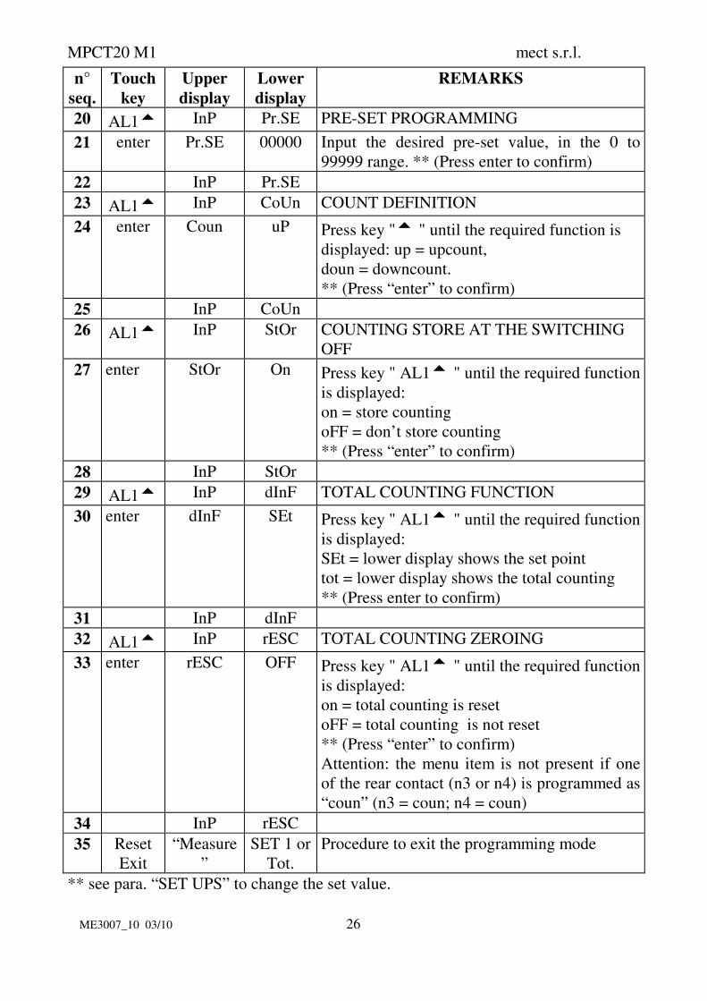
20 AL15 InP Pr.SE PRE-SET PROGRAMMING
21 enter Pr.SE 00000 Input the desired pre-set value, in the 0 to
99999 range. ** (Press enter to confirm)
22 InP Pr.SE
23 AL15 InP CoUn COUNT DEFINITION
24 enter Coun uP Press key "5 " until the required function is
displayed: up = upcount,
doun = downcount.
** (Press “enter” to confirm)
25 InP CoUn
26 AL15 InP StOr COUNTING STORE AT THE SWITCHING
OFF
27 enter StOr On Press key " AL15 " until the required function
is displayed:
on = store counting
oFF = don’t store counting
** (Press “enter” to confirm)
28 InP StOr
29 AL15 InP dInF TOTAL COUNTING FUNCTION
30 enter dInF SEt Press key " AL15 " until the required function
is displayed:
SEt = lower display shows the set point
tot = lower display shows the total counting
** (Press enter to confirm)
31 InP dInF
32 AL15 InP rESC TOTAL COUNTING ZEROING
33 enter rESC OFF Press key " AL15 " until the required function
is displayed:
on = total counting is reset
oFF = total counting is not reset
** (Press “enter” to confirm)
Attention: the menu item is not present if one
of the rear contact (n3 or n4) is programmed as
“coun” (n3 = coun; n4 = coun)
34 InP rESC
35 Reset
Exit
“Measure
”
SET 1 or
Tot.
Procedure to exit the programming mode
** see para. “SET UPS” to change the set value.

MPCT20 M1 mect s.r.l.
ME3007_10 03/10 27
6.2 UP-DOWN FUNCTION and TERMINAL CONFIGURATION
The Up/Down counting function (valid on pulse counter and timer functions), can be
selected by the menu “COUn” item or by “hold” and “reset” terminal board if they
are abled to select the counting direction (if you use the terminal board, you can’t use
the “COUn” menu item). To use the terminal board program the instrument as table
below shows.
When there is not link between the terminal board and the GND, the counting is UP.
If the terminal board is configurated as NPN, it has to be a low level (GND) to make
start the Down counting. If it is configurated as PNP, the terminal board has to be at
an high level (+16V: Val) -see PCB configuration-.
Table 10
n°°°°se
q.
Press
Key
Upper
display
Lower
display
Remarks
1 enter Touch the “enter” key to get into the
programming menu
1 enter PASS 0 000 In this phase the instrument asks for the
“password” number to protect the data
programmation. (see “Password function”)
2 AL15 SEL Ou
3 AL15 SEL InP
4 AL15 SEL CPAS
5 AL15 SEL C.nor TERMINAL CONFIGURATION
7 enter nor n 4 TERMINAL 4 CONFIGURATION
8 enter n 4 HoLd HoLd = terminal 4 with hold/stop function
COUn = terminal 4 with Up/Down function
rESt = if the instrument is programmed as
pulse counter the terminal 4 resets total
count.
Select by " AL15" key and confirm with
“enter”
9 nor n 4
10 AL15 nor n 3 TERMINAL 3 CONFIGURATION
11 enter n 3 rES rES = terminal 3 with reset function
COUn = terminal 3 with Up/Down function
rESt = if the instrument is programmed as
pulse counter the terminal 3 resets total
count.
Select by " AL15" key and confirm with
“enter”
12 nor n 3

MPCT20 M1 mect s.r.l.
ME3007_10 03/10 28
n°°°°se
q.
Press
Key
Upper
display
Lower
display
Remarks
13 Reset
Exit
measure SP1 Procedure to exit the programming mode
7.0 PULSE COUNTER AND TIMER ALARMS
Alarm values can be set in two different ways: by front panel keys or by standard
menu. In the first case it is possible to immediately set up two set point values, the
second one (MENU) drives you through all parameters of the instrument. The first
case you set the instrument, use “MENU” item to set all the parameters of the
instrument. The first step to do is to get in the complete menu and to set up the
alarms as requested.
7.1 “UP” COUNT MODE ALARMS
The MPCT20 M1 instruments have 2 contact relay alarms and it can also have one
exchange relay alarm (SR1F option).
ALARM 1 can be programmed in the following ways:
MANUAL MODE (nAn): reaching the count value set in SP of AL2, the instrument
activates the alarm 2 relay, reaching the count value set in SP of AL1, the instrument
activates the alarm 1 relay.
The count continues until a “reset” is performed, which sets to zero the display and
the alarms 1 and 2 outputs.
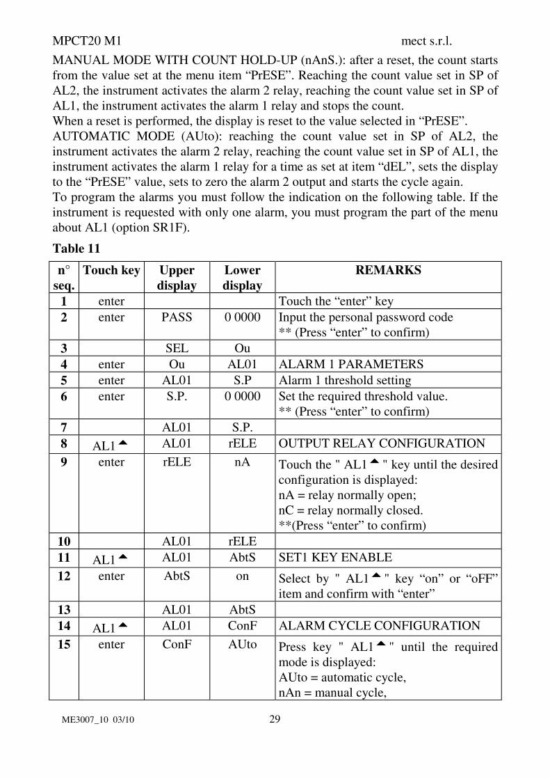
MANUAL MODE WITH COUNT HOLD-UP (nAn S.): reaching the count value set
in SP of AL2, the instrument activates the alarm 2 relay, reaching the count value set
in SP of AL1, the instrument activates the alarm 1 relay and stops the count. When a
“reset” is performed, this sets to zero the display and the alarms 1 and 2 outputs.
AUTOMATIC MODE (AUto): reaching the count value set in SP of AL2, the
instrument activates the alarm 2 relay, reaching the count value set in SP of AL1, the
instrument activates the alarm 1 relay for a time as set at item “dEL”, sets to zero the
display and the alarms 1 an 2 outputs and starts the cycle again. See the following
Table for programming the alarms.
For instruments with single alarm, the menu part for AL1 applies (option SR1F).
7.2 “DOWN” COUNT MODE ALARMS
In the down count mode, the alarms act as follows:
MANUAL MODE (nAn): after a reset, the count starts from the value set at the
menu item “PrESE”. Reaching the count value set in SP of AL1, the instrument
activates the alarm 1 relay, reaching the count value set in SP of AL2, the instrument
activates the alarm 2 relay.
Reaching zero, the count stops until a reset is performed, to start again the count
from the “PrESE” value.
MPCT20 M1 mect s.r.l.
ME3007_10 03/10 29
MANUAL MODE WITH COUNT HOLD-UP (nAnS.): after a reset, the count starts
from the value set at the menu item “PrESE”. Reaching the count value set in SP of
AL2, the instrument activates the alarm 2 relay, reaching the count value set in SP of
AL1, the instrument activates the alarm 1 relay and stops the count.
When a reset is performed, the display is reset to the value selected in “PrESE”.
AUTOMATIC MODE (AUto): reaching the count value set in SP of AL2, the
instrument activates the alarm 2 relay, reaching the count value set in SP of AL1, the
instrument activates the alarm 1 relay for a time as set at item “dEL”, sets the display
to the “PrESE” value, sets to zero the alarm 2 output and starts the cycle again.
To program the alarms you must follow the indication on the following table. If the
instrument is requested with only one alarm, you must program the part of the menu
about AL1 (option SR1F).
Table 11
n°
seq.
Touch key Upper
display
Lower
display
REMARKS
1 enter Touch the “enter” key
2 enter PASS 0 0000 Input the personal password code
** (Press “enter” to confirm)
3 SEL Ou
4 enter Ou AL01 ALARM 1 PARAMETERS
5 enter AL01 S.P Alarm 1 threshold setting
6 enter S.P. 0 0000 Set the required threshold value.
** (Press “enter” to confirm)
7 AL01 S.P.
8 AL15 AL01 rELE OUTPUT RELAY CONFIGURATION
9 enter rELE nA Touch the " AL15" key until the desired
configuration is displayed:
nA = relay normally open;
nC = relay normally closed.
**(Press “enter” to confirm)
10 AL01 rELE
11 AL15 AL01 AbtS SET1 KEY ENABLE
12 enter AbtS on Select by " AL15" key “on” or “oFF”
item and confirm with “enter”
13 AL01 AbtS
14 AL15 AL01 ConF ALARM CYCLE CONFIGURATION
15 enter ConF AUto Press key " AL15" until the required
mode is displayed:
AUto = automatic cycle,
nAn = manual cycle,

MPCT20 M1 mect s.r.l.
ME3007_10 03/10 30
n°
seq.
Touch key Upper
display
Lower
display
REMARKS
nAn.S = manual cycle with count hold-
up.
** (Press “enter” to confirm.)
16 AL01 ConF
17 AL15 AL01 dEL Automatic cycle TIME SETTING
18 enter dEL 00 25.0 Digit a value from 0 to 25.0 seconds.
** (Press “enter” to confirm)
19 AL01 dEL
20 AL24 nALL AL01
21 AL15 nALL AL02 ALARM 2 PARAMETERS
22 enter AL02 S.P Alarm 2 threshold setting
23 enter S.P. 0 0000 Set the required threshold value.
** (Press “enter” to confirm)
24 AL02 S.P.
25 AL15 AL02 rELE OUTPUT RELAY CONFIGURATION
26 enter RELE nA Touch the " AL15" key until the desired
configuration is displayed:
nA = relay normally open;
nC = relay normally closed.
**(Press “enter” to confirm)
27 AL02 rELE
28 AL15 AL02 AbtS SET1 KEY ENABLE
29 enter AbtS on Select by " AL15" key “on” or “oFF”
item and confirm with “enter”
30 AL02 AbtS
31 Reset
Exit
“measure” SET 1 Procedure to exit the programming mode
** see para. “SET UPS” to change the set value.
8.0 TIMER INSTALLATION NOTES
11.1 INSTALLATION PROCEDURE:
1 Make connections as indicated at pages: 7, 8 and 9
Terminal connections:
to use PNP sensors it’s necessary to modify an internal configuration of the
instrument (as described in the “PCB configuration” paragraph).
The 3 inputs are used in the “chronometer” mode (start, stop and reset), and in
“timer” mode is sufficient to use the input connected at the “hold” terminal and

MPCT20 M1 mect s.r.l.
ME3007_10 03/10 31
to program the “hold” item at “on”. By “hold” and “reset” terminal board it is
possible to choose the Up-Down counting (see “Up-Down function”).
2 Switch the unit on.
3 Program the functions based on the indications in the following table:
Table 12
n°
seq.
Press
Key
Upper
display
Lower
display
Remarks
1 enter Touch the “enter” key
2 enter PASS 0 000 In this phase the instrument asks for the of
“password” number to protect the data
programmation
(see “Password functon”)
3 SEL Ou
4 AL15 SEL InP
5 AL15 SEL CPAS
6 AL15 SEL C.nor
7 AL15 SEL dEF
8 AL15 SEL tYPE TYPE INSTRUMENT
9 enter tYPE CSEC rPn = rpm meter
Pr.h = hourly production meter
FrEq = frequency meter
CSEC = timer
CIn = counter
Select by “AL15 “key “CSEC” and
confirm by “enter”
10 SEL tYPE
11 Reset
Exit
“misura” SP 1
4. Program the functions of the following table to set the measuring scale (hours,
minutes, seconds), type of functioning (timer or chronometer), the reset
terminal board functioning, the counting type (Up or Down), the preset and
count memory at the switching off.
5. Set up the type of functioning by the “hold” item. With the “on” selection, the
instrument works as timer (comands hold and reset from the terminal board),
with “oFF” selection, the instrument works as chronometer (comands start,
stop and reset from the terminal board).
6. Define the reset key on the front panel by the “rES” item and the reset function
from the terminal board by the “nrES” item. The “reset” key on the front panel
works for the zeroing function of the diplay. If you don’t want this function,
you can exclude it through the programmation of the keyboard. The “reset”

MPCT20 M1 mect s.r.l.
ME3007_10 03/10 32
contact in the terminal board can work in a static way (till when the contact is
pressed, the instrument is at 0), or in a dinamyc way (immediate zeroing).
7. Set alarms
8. Set, if desired, the programming menu access code (password function)
9. The unit is now ready to be used.
Table 13
n°
seq.
Touch
key
Upper
display
Lower
dipsplay
NOTES
1 enter Touch the “enter” key
2 enter PASS 0 000 Input the personal password code
** (Press “enter” to confirm)
3 SEL Ou
4 AL15 SEL InP
5 enter InP SCAL SELECTION MEASURING SCALE
6 enter SCAL 00000 Set up the relative number for the desired scale:
To use scale 999.99 sec write the number “0”
To use scale 9999.9 sec write the number “1”
To use scale 99999 sec write the number “2”
To use scale 99999 min write the number “6”
To use scale 99999 h write the number “8”
To use scale 999 min 59 sec write the number “3”
To use scale 999 h 59 min write the number “7”
To use scale 9 h 59 min 59 sec write the number “4”
To use scale 23 h 59 min write the number “5”
** (Press “enter” to confirm)
7 InP SCAL
8 AL15 InP CoUn TYPE OF COUNTING SELECTION
9 enter CoUn uP Press key " AL15" till when on the display appears
the desired counting and confirm with “enter” (“uP”
for increasing counting and “doun” for decreasing
counting)
10 InP CoUn
11 AL15 InP Pr.SE PRESET FOR DOWN COUNTING
12 enter Pr.SE 10000 Write the number of the requested preset
** (Press “enter” to confirm)
13 InP Pr.SE
14 AL15 InP HOLd CHRONOMETER/TIMER SELECTION
15 enter HOLd on Selection the type of functioning: timer or
chronometer. Press key " AL15" till when on the
display appears the desired functioning and confirm

MPCT20 M1 mect s.r.l.
ME3007_10 03/10 33
n°
seq.
Touch
key
Upper
display
Lower
dipsplay
NOTES
with “enter”:
“on” = timer functioning ( hold and reset from the
terminal board)
“oFF” = chronometer functioning (start, stop and reset
from the terminal board)
16 InP HOLd
17 AL15 InP rES KEY RESET ON THE FRONT PANEL ENABLE
18 enter rES on Enable “reset” key from the front panel (the key reset
is “reset”). Press key " AL15" till when on the display
appears the desired functioning and confirm with
“enter” ( “on” for “reset” enabled key or “oFF” for
disabled key)
19 InP rES
20 AL15 InP nrES RESET TERMINAL BOARD CONFIGURATION
21 enter rES StAt StAt = the instrument keeps staying at zero till when
the terminal is short-circuited.
dIn = the instrument immediately goes to zero when
the terminal is short-circuited
Press key " AL15 " until the required function
appears on the display and confirm with “enter”
22 InP nrES
23 AL15 InP StOr COUNTING STORE AT THE SWITCHING OFF
24 enter StOr On Press key " AL15" till when on the display appears the
desired function:
on = counting stored
oFF = counting not stored
** (Press “enter” to confirm)
25 InP StOr
26 Reset
Exit
measure SET 1 Procedure to exit the programming mode
** see para. “SET UPS” to change the set value.
9.0 PASSWORD FUNCTION
Programmed data can be protected from unauthorised changes using the password
function.
The instrument is supplied with the password code set = 0; any number in the range 0
to 9999 can be used as access key to changing set data.
See following table for setting a customer password.

MPCT20 M1 mect s.r.l.
ME3007_10 03/10 34
The password code is requested when accessing the programming menu.
The instruments, after receiving the password number, can behave in two different
ways.
1) correct Password number: The user can gain access to programming menu and
modify any function or number that is flashing.
2) false Password number: The user can only see the programmed numbers but
cannot modify them.
Table 14
n°
seq.
Touch
key
Upper
display
Lower
display
NOTES
1 enter PASS 0 000 Touch the “enter” key
2 SEL Ou
3 AL15 SEL InP
4 AL15 SEL c.PAS PERSONAL PASSWORD
5 enter c.PAS 0 000 Input a Password number between 0 and 9999.
**(press “enter” to confirm)
6 SEL c.PAS
7 Reset
Exit
measure SET 1 procedure to exit the programming mode
** see para. “SET UPS” to change the set value.
WARNING. The code programmed at the item “c.PASS” by the user, shall be
entered in the field “n.PASS” every time access is required to the programming menu
to change the set data.
Should the user forget the programmed password code, our Customer Service should
be called to unlock the instrument.

MPCT20 M1 mect s.r.l.
ME3007_10 03/10 35
10.0 SET UPS
Instructions for changing and storing programming numbers. In this paragraph the
instructions to set up “SP1” item are shown but the procedure is the same for all
items.
Table 15
n°
seq.
Touch
key
Upper
display
Lower
display
REMARKS
1 AL01 SP1 example of changing set point value
2 enter SP1 0 0000 the display shows the first digit blinking
3 AL24 SP1 0 0 000 key “AL24”moves the blinking digit
4 AL15 SP1 0 1 000 key “AL15” increases the blinking digit
5 enter AL01 SP1 The value is stored and the display moves back
to the selected item.
! 11.0 NOTES
The instrument does not have a power on switch and an internal fuse, but it
immediately switch on when the correct voltage is applied (see the operating voltage
on the instrument label). Keep the power line separate from the signal lines.
For security reasons, it is necessary to provide externally a two phases switch and a
protective fuse near the instrument with easy access for the user.
Avoid the presence of others power elements, humidity, acid, heat sources, etc..
The instruments must be powered by safety isolating transformer or by selv type
power supply.
Mect srl is not responsible for damages to humans or goods for an improper use of
the instrument or not conforming to the characteristics of its instrument.
In mect srl there has an help desk office.


![RUDNvserosolymp.rudn.ru/upload/iblock/c21/08-558[1].pdf · K 3a¶BKe npwraraeTcq npe3ewraunq (B 3J1eKTPOHHOM BHAe Ha 6YMa}KHOM HOCHTeJ1e). ... C HJIJ1fOCTPaUH¶MH pa60HHx MeCT yqaCTHHKOB](https://img.pdfslide.us/doc/110x75/5f0df4547e708231d43ce706/1pdf-k-3abke-npwraraetcq-npe3ewraunq-b-3j1ektpohhom-bhae-ha-6ymakhom-hochtej1e.jpg)