Embed Size (px)
Citation preview

8/17/2019 ME-548 MasterCamX Workshop on..
http://slidepdf.com/reader/full/me-548-mastercamx-workshop-on 1/12
ME 548
NC MACHINING USINGMASTERCAM X
WORKSHOP ONE(of three)
LEGEND:
“Quotes” refers to a .
An arrow: refers to a sequence of selections.
FYI: - topics that will be of generalassistance to the user.
selection
For your information
->
James Baleshta
May 2006
8/17/2019 ME-548 MasterCamX Workshop on..
http://slidepdf.com/reader/full/me-548-mastercamx-workshop-on 2/12
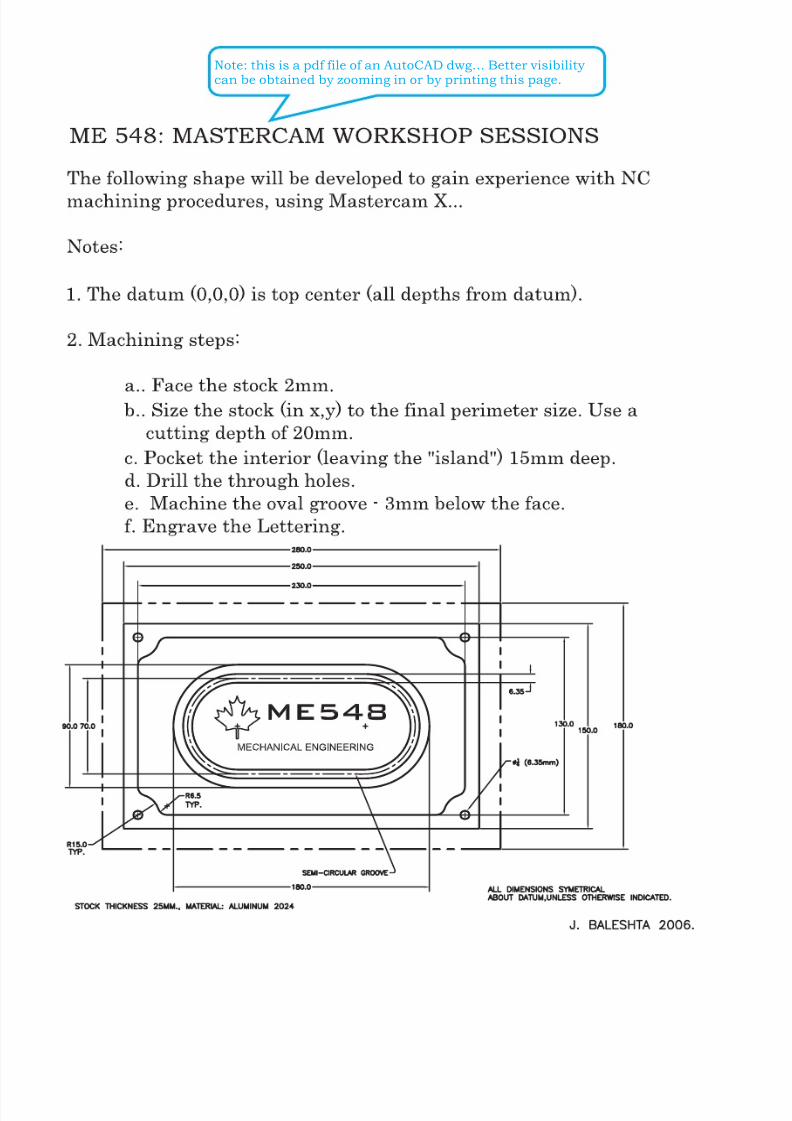
Note: this is a pdf file of an AutoCAD dwg... Better visibility can be obtained by zooming in or by printing this page.
8/17/2019 ME-548 MasterCamX Workshop on..
http://slidepdf.com/reader/full/me-548-mastercamx-workshop-on 3/12
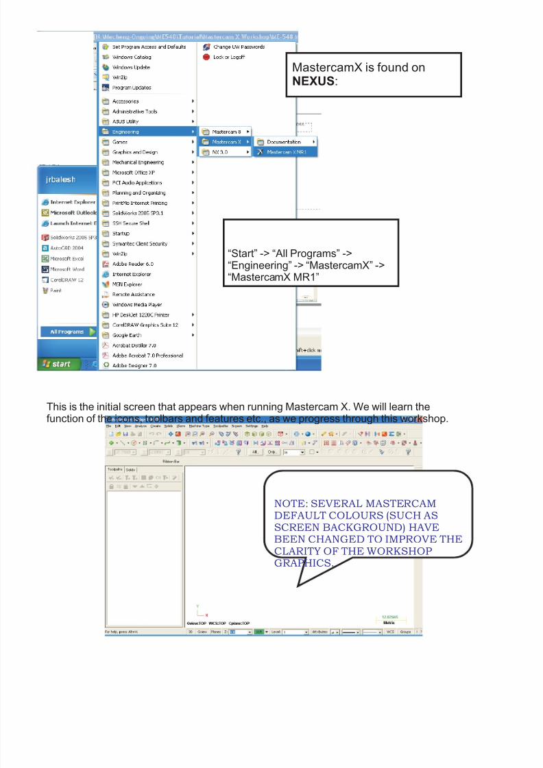
This is the initial screen that appears when running Mastercam X. We will learn thefunction of the icons, toolbars and features etc., as we progress through this workshop.
MastercamX is found on:NEXUS
“Start” -> “All Programs” ->
“Engineering” -> “MastercamX” ->“MastercamX MR1”
NOTE: SEVERAL MASTERCAMDEFAULT COLOURS (SUCH ASSCREEN BACKGROUND) HAVE
BEEN CHANGED TO IMPROVE THECLARITY OF THE WORKSHOPGRAPHICS.

8/17/2019 ME-548 MasterCamX Workshop on..
http://slidepdf.com/reader/full/me-548-mastercamx-workshop-on 4/12
We will begin by creating our geometry. The first step will be toremove the Tool OperationsManager to enlarge the graphicsarea on the screen. FYI: “Alt+O” will also toggle ( the screenvisiblilty of this feature .
on/off)
Next, in “Settings”->”System Configuration”check that the Default startupis “Metric”.
8/17/2019 ME-548 MasterCamX Workshop on..
http://slidepdf.com/reader/full/me-548-mastercamx-workshop-on 5/12
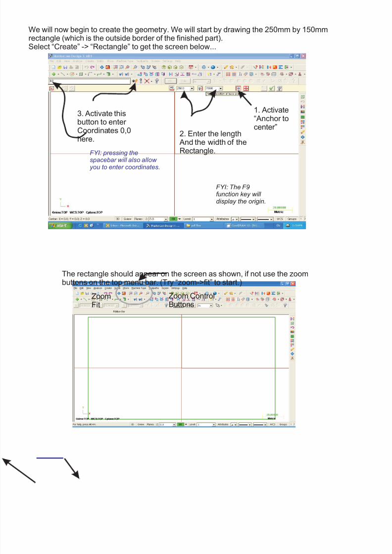
We will now begin to create the geometry. We will start by drawing the 250mm by 150mmrectangle (which is the outside border of the finished part).Select “Create” -> “Rectangle” to get the screen below...
The rectangle should appear on the screen as shown, if not use the zoombuttons on the top menu bar. (Try “zoom->fit” to start.)
Zoom ControlButtons
1. Activate“Anchor tocenter”
2. Enter the length And the width of theRectangle.
3. Activate thisbutton to enter Coordinates 0,0here.
FYI: pressing thewill also allow
you to enter coordinates.spacebar
FYI: The F9
function key will display the origin.
ZoomFit
8/17/2019 ME-548 MasterCamX Workshop on..
http://slidepdf.com/reader/full/me-548-mastercamx-workshop-on 6/12
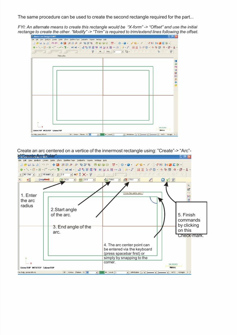
The same procedure can be used to create the second rectangle required for the part...
FYI: An alternate means to create this rectangle would be “X-form” -> “Offset” and use the initial rectange to create the other. “Modify” -> “Trim” is required to trim/extend lines following the offset.
Create an arc centered on a vertice of the innermost rectangle using: ”Create”-> “Arc”->”Create Arc Polar”.
1. Enter the arcradius
2.Start angleof the arc.
3. End angle of thearc.
4. The arc center point canbe entered via the keyboard(press spacebar first) or simply by snapping to thecorner.
5. Finishcommandsby clickingon this
Check-mark.
8/17/2019 ME-548 MasterCamX Workshop on..
http://slidepdf.com/reader/full/me-548-mastercamx-workshop-on 7/12
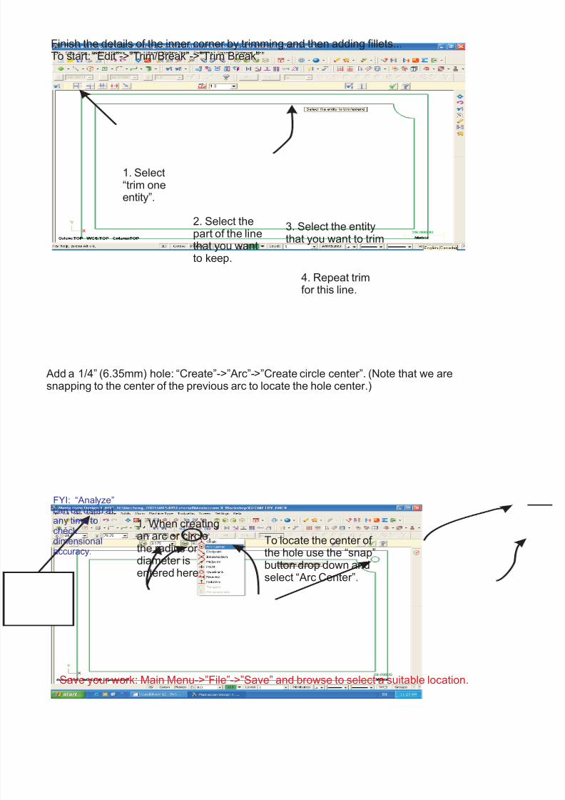
Finish the details of the inner corner by trimming and then adding fillets...To start: “Edit”->”Trim/Break”->”Trim Break”
Add a 1/4” (6.35mm) hole: “Create”->”Arc”->”Create circle center”. (Note that we aresnapping to the center of the previous arc to locate the hole center.)
Save your work: Main Menu->”File”->”Save” and browse to select a suitable location.
1. Select“trim oneentity”.
2. Select thepart of the linethat you wantto .keep
3. Select the entitythat you want to trim
4. Repeat trimfor this line.
1. When creatingan arc or circle,the radius or
diameter isentered here.
To locate the center of the hole use the “snap”button drop down andselect “Arc Center”.
FYI: “Analyze”can be used atany time tocheckdimensionalaccuracy.
8/17/2019 ME-548 MasterCamX Workshop on..
http://slidepdf.com/reader/full/me-548-mastercamx-workshop-on 8/12
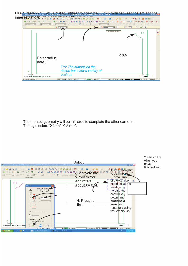
Use “Create”-> “Fillet” -> “Fillet Entities” to draw the 6.5mm radii between the arc and theinner rectangle.
FYI: The buttons on theribbon bar allow a variety of settings
Enter radiushere.
R 6.5
The created geometry will be mirrored to complete the other corners...To begin select “Xform”->”Mirror”.
1. The geometryto be mirrored(3 arcs, onecircle) can be
byholding thecontrol keydown, anddragging aselectionrectangle usingthe left mouse
selected with a
window
3. Activate they-axis mirror and rotate
about X= 0 pt.
4. Press tofinish
Select
2. Click herewhen youhavefinished your
8/17/2019 ME-548 MasterCamX Workshop on..
http://slidepdf.com/reader/full/me-548-mastercamx-workshop-on 9/12
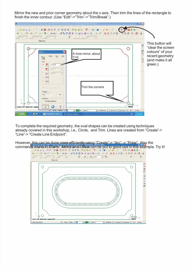
Mirror the new and prior corner geometry about the x axis. Then trim the lines of the rectangle tofinish the inner contour. (Use “Edit”->”Trim”->”Trim/Break”.)
This button will
“clear the screencolours” of your recent geometry(and make it allgreen.)
To complete the required geometry, the oval shapes can be created using techniquesalready covered in this workshop, i.e., Circle, and Trim. Lines are created from “Create”->“Line”-> “Create Line Endpoint”.
However, this can be done more efficiently using “Create”-> “Arc” -> “Polar”. Also thecommands found in Xform: and can be put to good use in this example. Try it!Mirror Offset
X-Axis mirror, aboutY=0.
Trim the corners
8/17/2019 ME-548 MasterCamX Workshop on..
http://slidepdf.com/reader/full/me-548-mastercamx-workshop-on 10/12
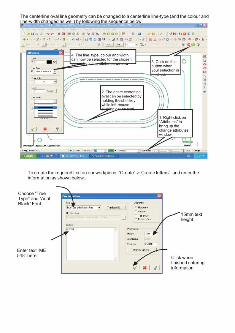
2. The entire centerlineoval can be selected byholding the shift keywhile left-mouseclicking on the oval.
3. Click on thisbutton whenyour selection isfinished.
1. Right click on“Attributes” tobring up thechange attributeswindow.
4. The line: type, colour and width
can now be selected for the chosengeometry in the attributes window
The centerline oval line geometry can be changed to a centerline line-type (and the colour andline-width changed as well) by following the sequence below:
To create the required text on our workpiece: “Create”->”Create letters”, and enter theinformation as shown below...
Enter text “ME548” here
Choose “TrueType” and “ArialBlack” Font.
15mm textheight
Click whenfinished enteringinformation.
8/17/2019 ME-548 MasterCamX Workshop on..
http://slidepdf.com/reader/full/me-548-mastercamx-workshop-on 11/12
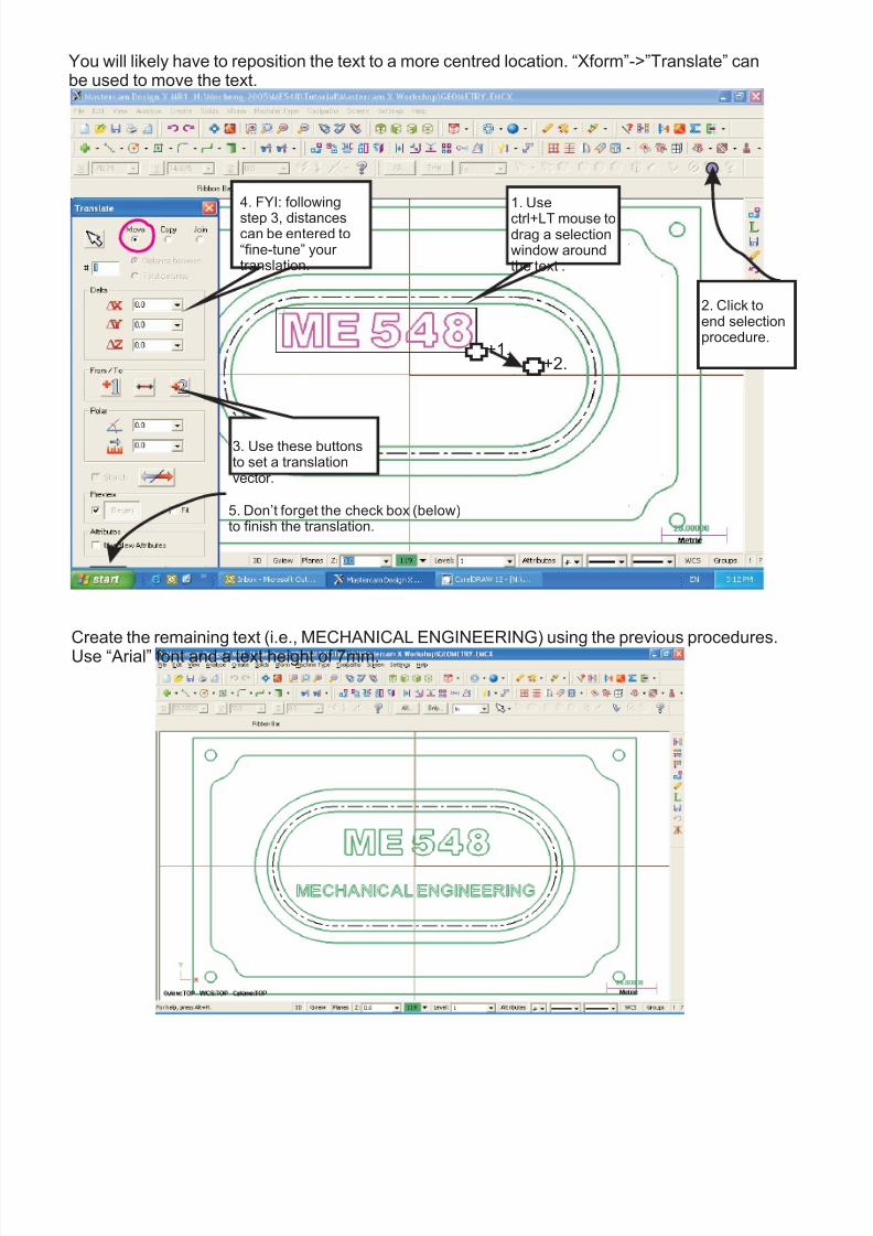
You will likely have to reposition the text to a more centred location. “Xform”->”Translate” canbe used to move the text.
1. Use
ctrl+LT mouse todrag a selectionwindow aroundthe text .
3. Use these buttonsto set a translationvector.
4. FYI: following
step 3, distancescan be entered to“fine-tune” your translation.
+1.+2.
5. Don’t forget the check box (below)to finish the translation.
Create the remaining text (i.e., MECHANICAL ENGINEERING) using the previous procedures.Use “Arial” font and a text height of 7mm.
2. Click toend selectionprocedure.

8/17/2019 ME-548 MasterCamX Workshop on..
http://slidepdf.com/reader/full/me-548-mastercamx-workshop-on 12/12
IMPORTING GEOMETRY: X
importing and merging the maple leaf
To import geometry into Mastercam , the following sequence of commands can be used...
Steps to seen below:Geometry can be created in a program such as Corel Draw or AutoCAD and saved as a DXF file.
In Mastercam: First save the current file (in case you mess up).
Then...
“File”->”File Merge Pattern”
Files of Type: ”AutoCAD Files”File Name: “MAPLE LEAF.DXF”
This should bring in the leaf and merge the new geometry with our earlier work.
(FYI: geometry must be vector based and not bitmaps.)
FYI: Following a merge, scaling and/or translating of the new geometry is often required for proper sizing and alignment. Remember that you can select the leaf (especially if it is overlaid over other geometery) with a “Shift+ LT Mouse” click, then translate (move) it.
The geometry is now all complete... Save your work and the next workshop will deal with toolpathcreation!