Embed Size (px)
Citation preview
ME 5243:ADVANCED MECHANISM DESIGN
• Quiz• Cam Sizing Exercises
– Double Dwell– Conveyor Chase
Class #23Cam Sizing

2
Notes
• Draft Report: Due Thursday, Nov 30
• Project Presentations: Dec 5 & 7– E-mail me with conflicts
4
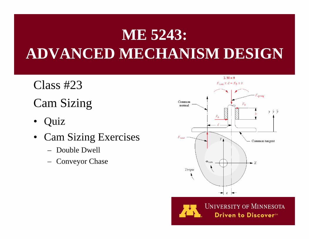
Questions from Video: Cam Sizing
5
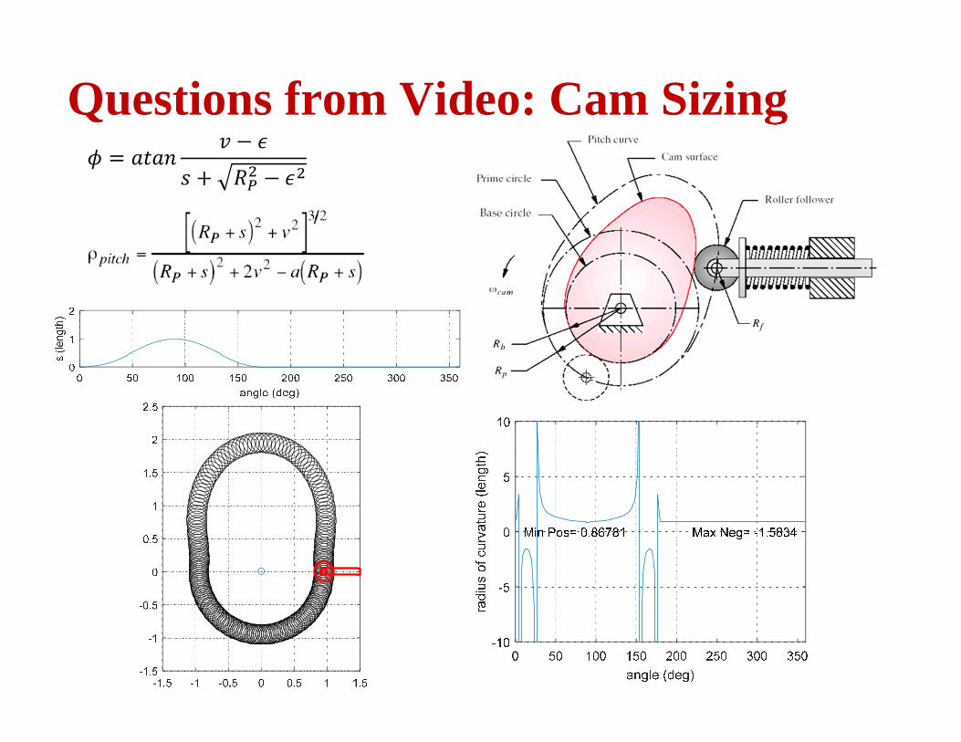
Double Dwell Cam Sizing
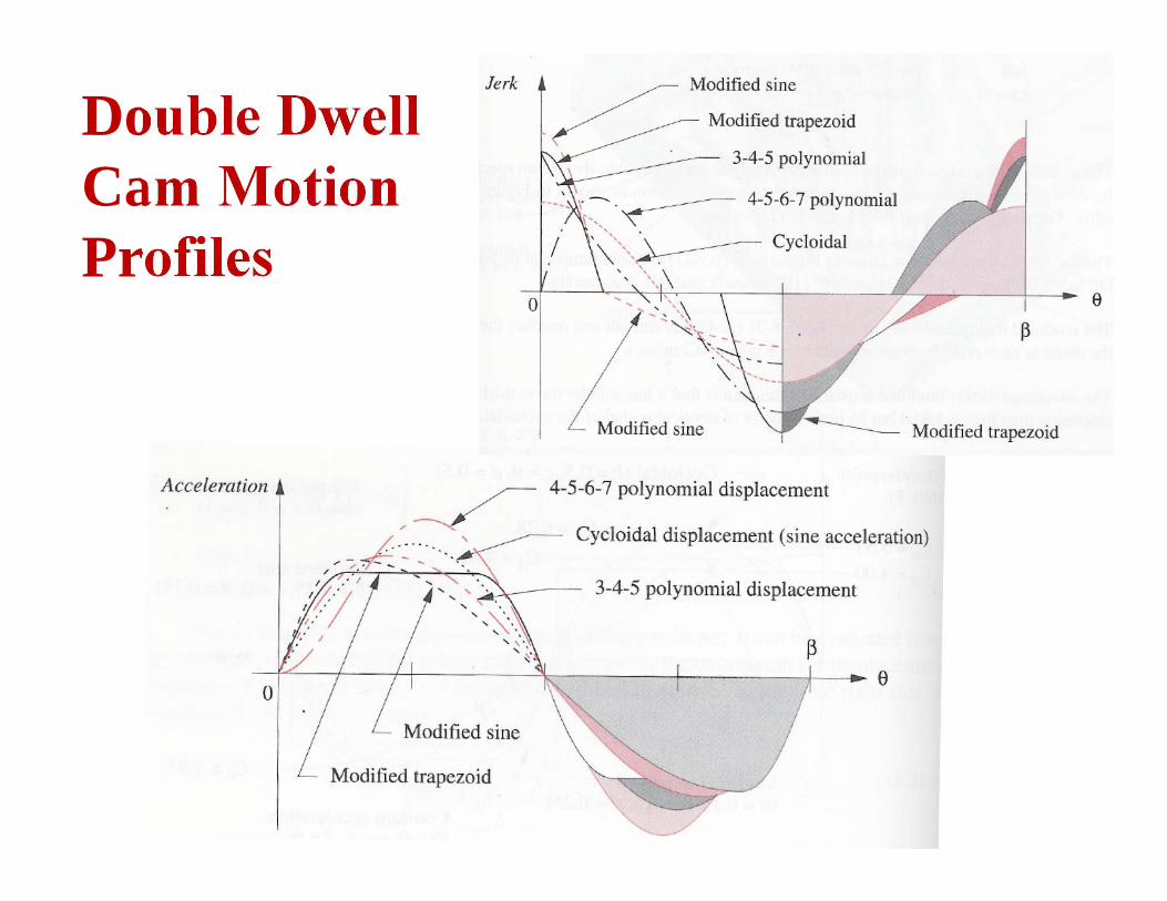
1. Cam motion profiles?
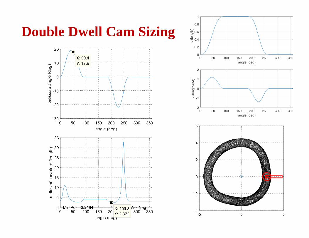
2. Pressure angle at 50º?– Acceptable?
3. Radius of curvature at 200°?– Acceptable?
6
Double Dwell Cam Motion Profiles
7
Double Dwell Cam Sizing
8
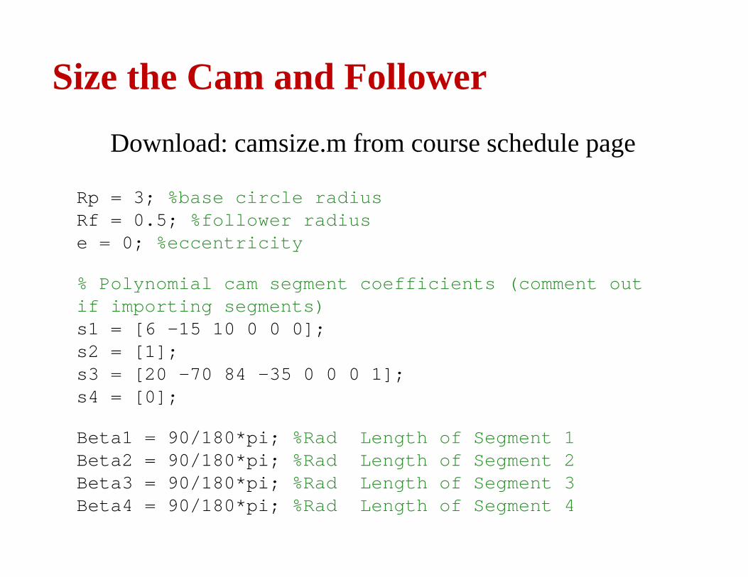
Size the Cam and Follower
Download: camsize.m from course schedule page
Rp = 3; %base circle radiusRf = 0.5; %follower radiuse = 0; %eccentricity
% Polynomial cam segment coefficients (comment out if importing segments)s1 = [6 -15 10 0 0 0];s2 = [1];s3 = [20 -70 84 -35 0 0 0 1];s4 = [0];
Beta1 = 90/180*pi; %Rad Length of Segment 1Beta2 = 90/180*pi; %Rad Length of Segment 2Beta3 = 90/180*pi; %Rad Length of Segment 3Beta4 = 90/180*pi; %Rad Length of Segment 4
9
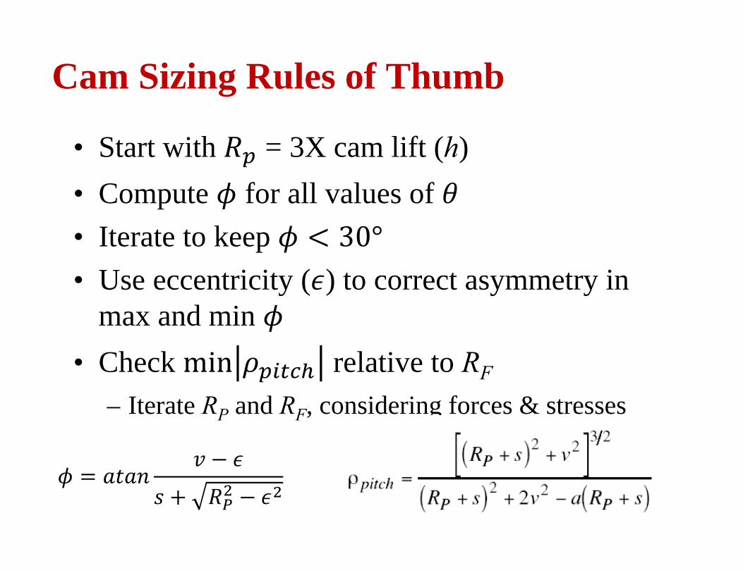
Cam Sizing Rules of Thumb
• Start with = 3X cam lift (h)• Compute for all values of • Iterate to keep • Use eccentricity ( ) to correct asymmetry in
max and min • Check relative to RF
– Iterate RP and RF, considering forces & stresses
10
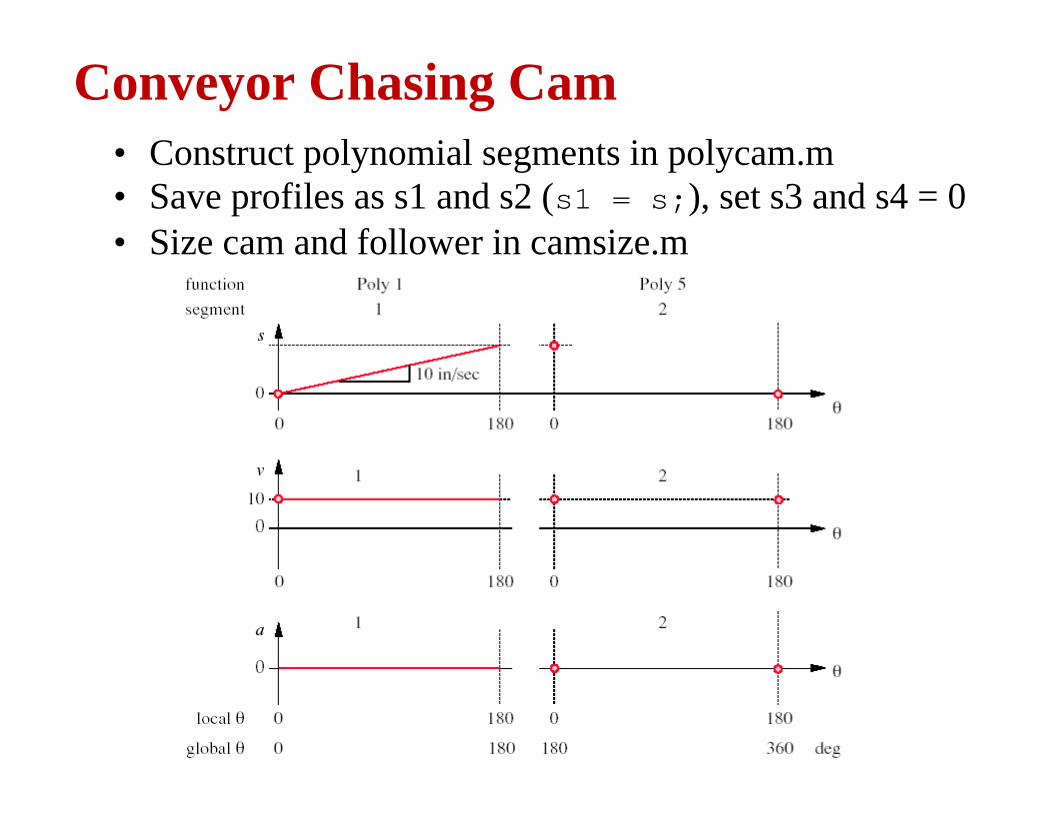
Conveyor Chasing Cam• Construct polynomial segments in polycam.m• Save profiles as s1 and s2 (s1 = s;), set s3 and s4 = 0• Size cam and follower in camsize.m
11
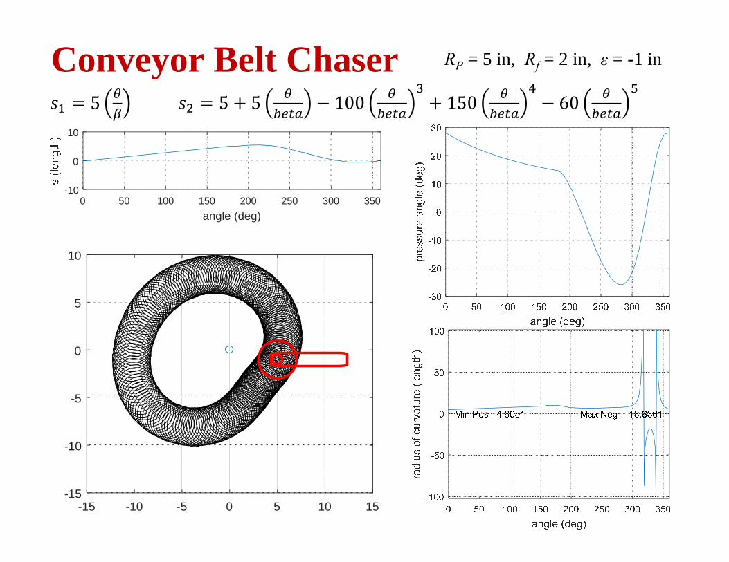
Conveyor Belt Chaser RP = 5 in, Rf = 2 in, ε = -1 in
0 50 100 150 200 250 300 350angle (deg)
-10
0
10
0 50 100 150 200 250 300 350angle (deg)
-5
0
5
0 50 100 150 200 250 300 350angle (deg)
-10
0
10
0 50 100 150 200 250 300 350angle (deg)
-20
0
20
-15 -10 -5 0 5 10 15-15
-10
-5
0
5
10
5 5 5 100 150 60
12
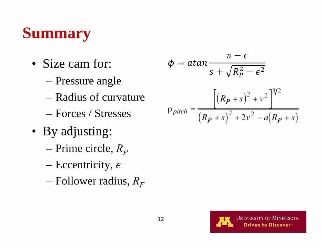
• Size cam for:– Pressure angle– Radius of curvature– Forces / Stresses
• By adjusting:– Prime circle, RP– Eccentricity, – Follower radius, RF
Summary
13
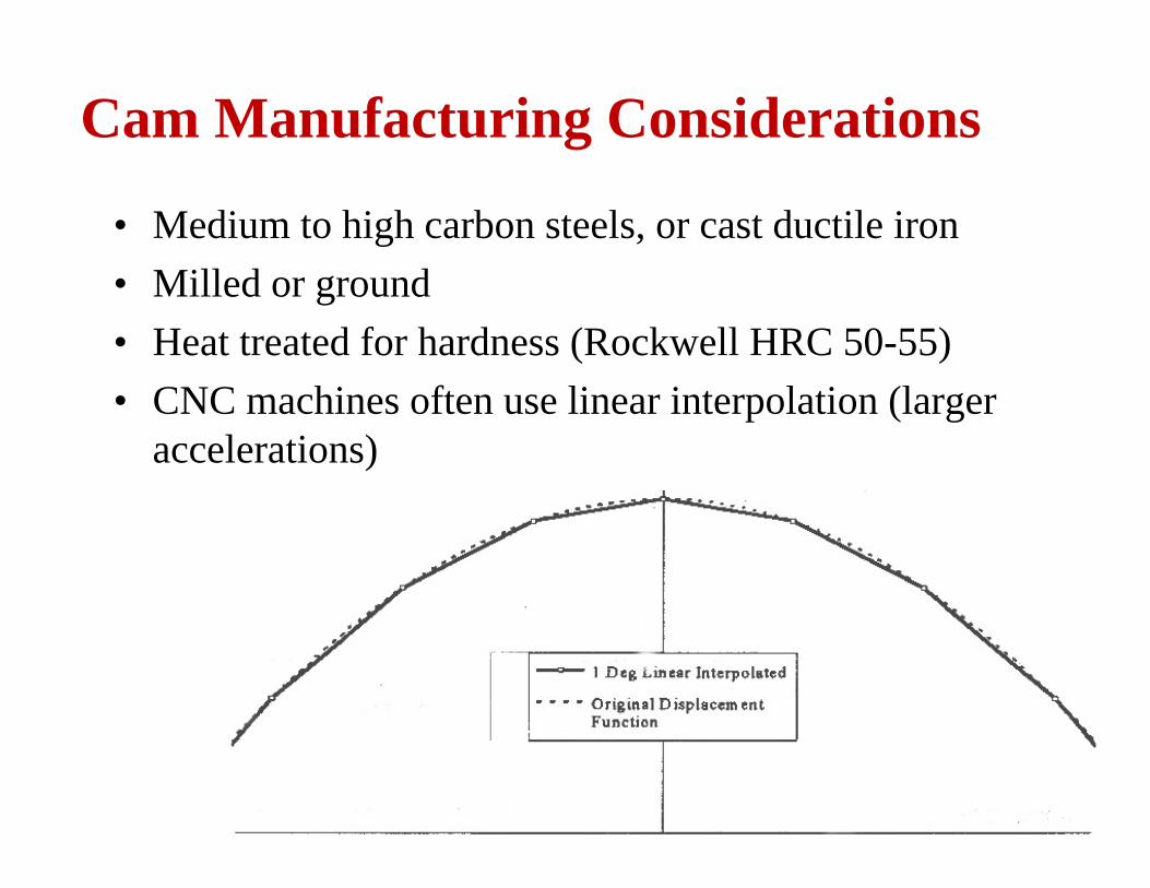
Cam Manufacturing Considerations
• Medium to high carbon steels, or cast ductile iron• Milled or ground• Heat treated for hardness (Rockwell HRC 50-55)• CNC machines often use linear interpolation (larger
accelerations)
14
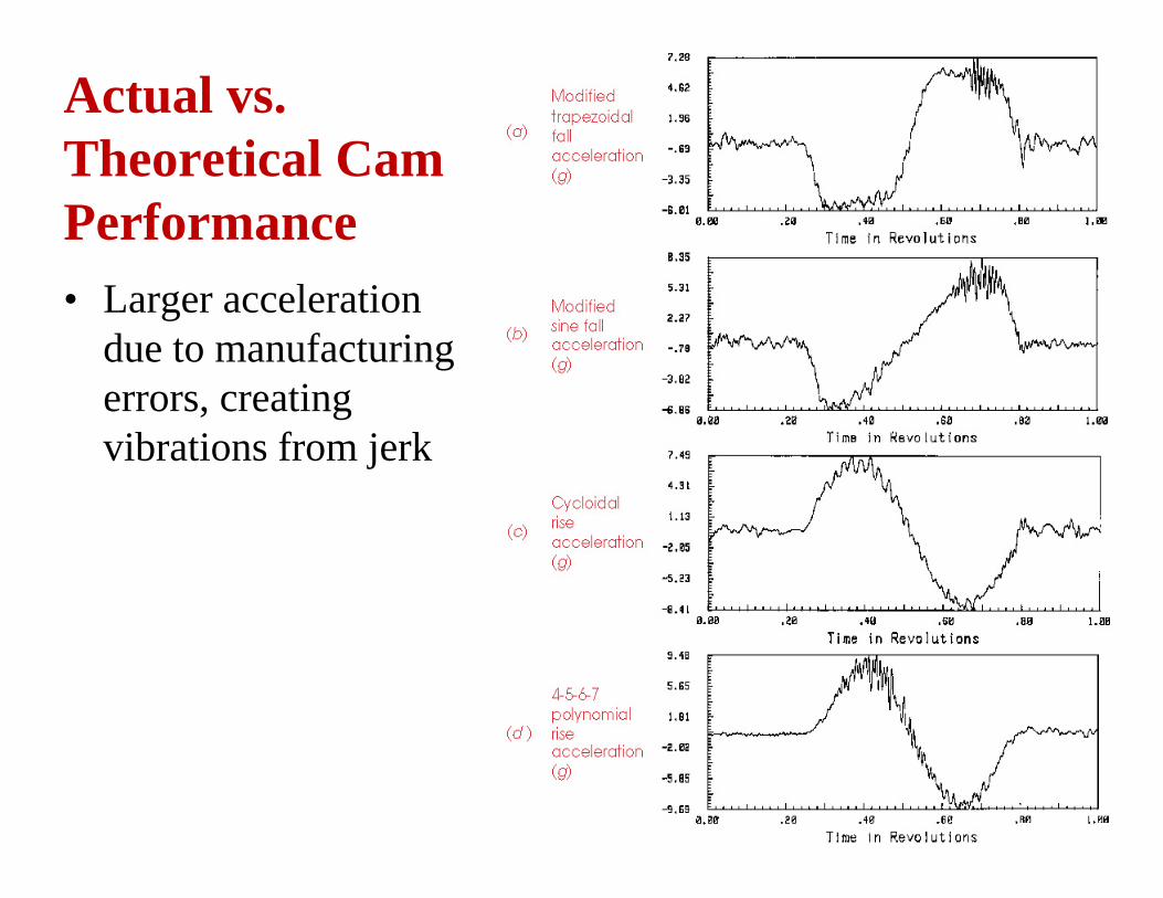
Actual vs. Theoretical Cam Performance• Larger acceleration
due to manufacturing errors, creating vibrations from jerk
15
Practical Design Considerations
• Translating or oscillating follower?• Force or Form-Closed?
– Follower Jump vs. Crossover Shock• Radial or Axial Cam?• Roller or Flat-Faced Follower?• To Dwell or Not to Dwell?• To Grind or not to Grind?• To Lubricate or Not to Lubricate?