Embed Size (px)
Citation preview

1
ME 400: Project and Thesis
Design & Fabrication of an Alpha Type Stirling Engine
Session 2005 – 2006
Accomplished by:
Md. Reaz Mohiuddin (Student # 0210022)Nusair Mohammed Ibn Hasan (Student # 0210049)
Under the Supervision of
Dr. Md. EhsanProfessor, Department of Mechanical Engineering
Bangladesh University of Engineering and Technology (BUET)Dhaka.

2
Declaration
The contents presented herein are the result of a undergraduate final year project
and research performed in the 2005-06 session at Bangladesh University of Engineering
and Technology (BUET), Dhaka. It has been done by the undersigned students and has not
been submitted anywhere for the award of any degree or diploma.
Signature of the Authors:
Md. Reaz Mohiuddin
(Student # 0210022) ______________________________
Nusair Mohammed Ibn Hasan
(Student # 0210049) ______________________________
Project Supervisor:
____________________________
Dr. Md. Ehsan
Professor
Department of Mechanical Engineering
BUET
Date: ______________

3
Acknowledgment
We deeply acknowledge our sense of gratitude; sincere appreciation and great
indebtness to our honorable project supervisor Dr. Md. Ehsan, Department of Mechanical
Engineering, BUET for his valuable suggestions, inspiration, encouragement and support
throughout the project work.
We would like give our special thanks to BUET Machine Shop, especially Mr. Abul
Hasnat (Asst. Foreman), Mr. Manik C. Roy (Sr. Machine Operator) except whose cordial
assistance and technical skill it would be quite tiresome to finish the project successfully.
Special Thanks goes to Mr. Awal, Fuel Testing Laboratory, Department of
Mechanical Engineering, BUET, for his endless support throughout the experimentation
phase.
We would also like to thank our fellow classmates, especially, Didarul Bahar
Bhuiyan, Sourav Barman and Joydip Saha for their help and support in several matters.
And last of all, our parents. Without their support, it would be very difficult for us
to complete the project.

4
Abstract
The projects aim was to develop a working model of Stirling cycle external
combustion engine from available thermodynamic analysis. Though the technology dates
back to early 1920’s, yet the only successful application has been made only by the
department of defense of the United States of America. Seeing the potential of this
technology, an effort was made to develop an engine which can give meaningful work
output. This type of engine if developed successfully allows tremendous fuel type
flexibility for being an external combustion engine and also works with higher efficiency
than any other regular I.C engine. Another advantage would be its low noise emission. In
this project a working model was fabricated using locally available material and then to
troubleshoot the physical model, a mathematical simulation model was also developed. The
working model was tested and results were compared to results available from the
simulation. This report gives a total description of the entire project.

5
Contents
1. Abstract ……………………… 03
2. Contents ……………………… 04
3. Concept ……………………… 06
4. Classification ……………………… 12
5. Application ……………………… 18
6. History ……………………… 22
7. Design Criteria ……………………… 26
8. Fabrication Details ……………………… 47
9. Mathematical Model ……………………… 42
10. First Order Isothermal Model of an α Stirling ……………………… 44
11. Computer Simulation ……………………… 48
12. Experimentation & Result Analysis ……………………… 57
13. Discussion ……………………… 67
14. Conclusion ……………………… 69
15. Recommendations ……………………… 70
16. References ……………………… 72
17. Appendix: Detailed Drawings of Prototype ……………………… 73

6
Section 1
Background Study

7
Concept
Global environment protection has come to be more and more important recently,
and demand for engines with high efficiency and low pollution is increasing. Stirling
engines have a potential solution to the above problems, because they have excellent
characteristics which are high thermal efficiency, multi-fuel capability and low pollution.
Engines operating on the Stirling Cycle are the most efficient practical heat engines ever
built. As an engine they can run on any heat source (including solar heating), and if
combustion-heated, they produce very low levels of harmful emissions.
Basic Idea:
Fig 3.1: Expansion and contraction of gas due to heating and cooling
Any gas expands under heating and it contracts when cooled (Figure 1.1). If we
consider a closed quantity of gas in a flexible chamber, the chamber itself would also
expand and contract with the gas. When the gas is heated and cooled simultaneously, the
expansion and contraction of the gas can be converted to reciprocating or rotary motion
depending on the mechanism used. This is the general idea behind any Stirling cycle
engine.

8
Stirling Cycle:
Stirling engines run on a cycle consisting of two constant volume processes and two
isothermals. It is known as the Stirling Cycle. In practice, the working gas is heated and
cooled in two different regions rather than simultaneously heating and cooling the gas in
the same region. These are termed as the hot end and the cold end. To carry out the
isothermal processes, the temperatures of the two ends are kept fixed. The cycle also
consists of a regenerator. In an ideal Stirling cycle engine the components of the machine
interact to produce four separate thermodynamic processes. These processes are shown on
pressure-volume and temperature-entropy diagrams in Figure 1.2
Fig 3.2: P-V and T-S Diagram of Stirling Cycle
1 – 2: Isothermal (constant temperature) Expansion –
The high pressure working gas absorbs heat from the hot space and expands
isothermally, thus doing work on the hot end piston.
2 – 3: Isochoric (constant volume) Displacement –
The hot end piston transfers all the working gas isochorically through the
regenerator to the cold end of the engine. Heat is absorbed from the gas as it passes
through the regenerator, thus lowering the temperature of the gas to that of the cold space.
As the temperature reduces, the gas pressure drops significantly.

9
3 – 4: Isothermal Compression –
The cold end piston does work on the gas and compresses it isothermally at cold
end temperature, hence rejecting heat to the cold space. Because the gas is at low pressure,
less work is required for compression than was obtained from the gas during expansion.
The cycle therefore has a positive work output.
4 – 1: Isochoric Displacement –
The cold end piston transfers all the working gas isochorically through the
regenerator to the hot end of the engine. Heat is delivered to the gas as it passes through
the regenerator, thus raising the temperature of the gas to that of the hot space. As the
temperature rises, the gas pressure increases significantly, and the system returns to its
initial conditions.

10
Engine Components:
All the processes described before are carried out by several engine components in
practice. There are five main components in a Stirling cycle engine. These are –
1. Working Gas – The Stirling cycle is a closed cycle and the various thermodynamic
processes are carried out on a working gas that is trapped within the system.
Working gas can be air, hydrogen, helium etc.
Fig 3.3: Block diagram of Stirling Cycle
2. Heat Exchangers – Two heat exchangers are used to transfer heat across the
system boundary. A heat absorbing heat exchanger transfers heat from outside the
system into the working gas and a heat rejecting heat exchanger transfers heat from
the working gas to outside the system. For example, on an engine the heat

11
absorbing heat exchanger might transfer heat from a burner into the working gas,
and the heat rejecting heat exchanger might transfer heat from the working gas to
coolant in a water jacket.
3. Displacer Mechanism – This moves (or displaces) the working gas between the hot
and cold ends of the machine (via the regenerator).
Fig 3.4: Schematic diagram of Stirling Cycle
4. Regenerator – It acts both as a thermal barrier between the hot and cold ends of the
engine and also as a thermal storage for the cycle. Physically a regenerator usually
consists of a mesh material and heat is transferred as the working gas is blown
through the regenerator mesh. When the working gas is displaced from the hot end
of the engine (via the regenerator) to the cold end of the machine, heat is deposited
in the regenerator, and the temperature of the working gas is lowered. When the
reverse displacement occurs, heat is withdrawn from the regenerator again, and the
temperature of the working gas is raised.
5. Expansion/Compression Mechanism – this expands and/or compresses the
working gas. In an engine this mechanism produces a net work output. Same
components can be used as displacer and expansion/compression mechanism
depending on engine type.

12
Pressurization:
Most high performance Stirling engines are pressurized, that is the mean pressure of
the working fluid is above atmospheric pressure. This increases the mass of working fluid
processed per cycle, thus, all other things being equal, the engine produces more power.
Unfortunately all other things seldom are equal, and to realize the potential of
pressurization larger heat exchangers (including the regenerator) are required. This
inevitably increases dead space and possibly gas flow resistance, both of which tend to
reduce power output. Like most aspects of Stirling engine design, optimization of this
aspect is a delicate balancing act between often conflicting requirements.
Advantages & Disadvantages of Stirling engines:
Advantages Disadvantages
Multi Fuel Capability
Quiet Operation
Higher Manufacturing Cost
Flat Part Load Characteristics
Low Pollutant Emissions
Lower Seal Reliability
Low Cycle Torque Variation
Low Lubricant Consumption
Larger Radiator Sizes
Low Internal Wear Rates
Variety in Design
Complex Control System

13
Classification
Generally engineers classify Stirling engines into three distinct types. These are α
(alpha) type, β (beta) type and γ (gamma) type. The Alpha type engine relies on
interconnecting the power pistons of multiple cylinders to move the working gas, with the
cylinders held at different temperatures. The Beta and Gamma type Stirling engines use a
displacer piston to move the working gas back and forth between hot and cold heat
exchangers in the same cylinder. Changes to the configuration of mechanical Stirling
engines continue to interest engineers and inventors. Notably, some are in pursuit of the
rotary Stirling engine; the goal here is to convert power from the Stirling cycle directly into
torque, a similar goal to that which led to the design of the rotary combustion engine. No
practical engine has yet been built but a number of concepts, models and patents have been
produced. There is also a field of "free piston" Stirling cycles engines, including those with
liquid pistons and those with diaphragms as pistons.

14
α (alpha) type:
Fig. 4.1: Schematic diagram of an alpha Stirling engine
An alpha Stirling contains two separate power pistons in separate cylinders, one hot
piston and one cold piston. The hot piston cylinder is situated inside the higher temperature
heat exchanger and the cold piston cylinder is situated inside the low temperature heat
exchanger. This type of engine has a very high power-to-volume ratio but has technical
problems due to the usually high temperature of the hot piston and the durability of its
seals.
(a) Expansion – At this point, most of the gas in the system has just been driven into the
hot cylinder. The gas heats and expands driving both pistons inward.
(b) Transfer – At this point, the gas has expanded. Most of the gas (about 2/3rds) is still
located in the hot cylinder. Flywheel momentum carries the crankshaft the next 90 degrees,
transferring the bulk of the gas to the cold cylinder.

15
(a) (b)
(c) (d)
Fig 4.2: (a) Expansion (b) Transfer (c) Contraction and (d) Transfer of gas
(c) Contraction – Now the majority of the expanded gas has been shifted to the cool
cylinder. It cools and contracts, drawing both pistons outward.
(d) Transfer – The now contracted gas is still located in the cold cylinder. Flywheel
momentum carries the crank another 90 degrees, transferring the gas to back to the hot
cylinder to complete the cycle.

16
β (beta) type:
Fig 4.3: Schematic diagram of a beta Stirling engine
A beta Stirling has a single power piston arranged within the same cylinder on the
same shaft as a displacer piston. The displacer piston is a loose fit and does not extract any
power from the expanding gas but only serves to shuttle the working gas from the hot heat
exchanger to the cold heat exchanger. When the working gas is pushed to the hot end of the
cylinder it expands and pushes the power piston. When it is pushed to the cold end of the
cylinder it contracts and the momentum of the machine, usually enhanced by a flywheel,
pushes the power piston the other way to compress the gas. Unlike the alpha type, the beta
type avoids the technical problems of hot moving seals.
(a) Expansion – At this point, most of the gas in the system has just been driven to the hot
end of the cylinder. The gas heats and expands driving the piston outward.
(b) Transfer – At this point, the gas has expanded. Most of the gas is still located in the
hot end of the cylinder. Flywheel momentum carries the crankshaft the next quarter turn.
The bulk of the gas is transferred around the displacer to the cool end of the cylinder.

17
(a) (b)
(c) (d)
Fig 4.4: (a) Expansion (b) Transfer (c) Contraction and (d) Transfer of gas
(c) Contraction – Now the majority of the expanded gas has been shifted to the cool end.
It contracts, drawing the piston inward.
(d) Transfer – The contracted gas is still located near the cool end of the cylinder.
Flywheel momentum carries the crank another quarter turn, moving the displacer and
transferring the bulk of the gas back to the hot end of the cylinder.

18
γ (gamma) type:
Fig. 4.5: Schematic diagram of a gamma Stirling engine
A gamma Stirling is simply a beta Stirling in which the power piston is mounted in
a separate cylinder alongside the displacer piston cylinder, but is still connected to the same
flywheel. The gas in the two cylinders can flow freely between them but remains a single
body. This configuration produces a lower compression ratio but is mechanically simpler
and often used in multi-cylinder Stirling engines.

19
Application
Combined Heat and Power Applications:
Fig. 5.1: Yacht propelled by onboard WhisperGen CHP System
Combined heat and power (CHP) is an economical source of mechanical or
electrical power, which uses a heat source in conjunction with a secondary heating
application, usually a pre-existing energy use, such as an industrial process. Usually the
primary heat source will enter the Stirling engine heater, since that will usually be at a
higher temperature than the heating application, and the "waste" heat from the engine's
heater will supply the secondary heating application. The power produced by the engine is
often used to run an industrial or agricultural process, which in turn creates biomass waste
refuse that can be used as free fuel for the engine, thus reducing waste removal costs. The
overall process is very resourceful, thus making it efficient and cost-effective overall.

20
Solar Power Generation:
Placed at the focus of a parabolic mirror a Stirling engine can convert solar energy
to electricity with efficiency better than non-concentrated photovoltaic cells, and
comparable to Concentrated Photovoltaic.
Stirling Cryocoolers:
Fig. 5.2: Stirling Cryocooler
Any Stirling engine will also work in reverse as a heat pump: i.e. when a motion is
applied to the shaft, a temperature difference appears between the reservoirs. One of their
modern uses is in refrigeration and cryogenics.
Nuclear Power:
There is a potential for nuclear-powered Stirling engines in electric power
generation plants. Replacing the steam turbines of nuclear power plants with Stirling
engines might simplify the plant, yield greater efficiency, and reduce the radioactive by-
products. A number of breeder reactor designs use liquid sodium as coolant. If the heat is to
be employed in a steam plant, a water/sodium heat exchanger is required, which raises
some concern as sodium reacts violently with water. A Stirling engine obviates the need for
water anywhere in the cycle.

21
Automotive engines:
It is often claimed that the Stirling engine has too low a power/weight ratio and too
long a starting time for automotive applications. There have been at least two automobiles
exclusively powered by Stirling engines that were developed by NASA, as well as earlier
projects by Ford and American Motor Companies. The main difficulties involved in using
the Stirling engine in an automotive application are start-up time, acceleration response,
shut-down time, and weight, not all of which have ready-made solutions. Many people
believe that hybrid electric drive systems can bypass all of these setbacks.
Aircraft Engines:
Stirling engines hold theoretical promise as aircraft engines. They are quieter, less
polluting, gain efficiency with altitude, are more reliable due to fewer parts and the absence
of an ignition system, produce much less vibration (airframes last longer) and safer, less
explosive fuels may be used.
Geothermal Energy:
Some believe that the ability of the Stirling engine to convert geothermal energy to
electricity and then to hydrogen may well hold the key to replacement of fossil fuels in a
future hydrogen economy. This belief was also founded on research conducted at Los
Alamos Labs that began as a hot dry rocks research, but later calculated the near limitless
energy potential from molten rock on one side of Stirling engine and ocean water on the
other. Although currently the most feasible source of commercial electrical generation is
solar, very long range predictions show advances in deep drilling and development of
methods to work with molten rock could yield exponential levels of clean energy
generation for thousands of years.

22
Low Temperature Difference Engines:
Fig. 5.3: LTD Stirling MM – 7
A low temperature difference (Low Delta T, or LTD) Stirling engine will run on
any low temperature differential, for example the difference between the palm of a hand
and room-temperature or room temperature and an ice cube. Usually they are designed in a
gamma configuration, for simplicity, and without a regenerator. They are typically
unpressurized, running at near-atmospheric pressure.

23
History
Stirling's air engine (as it is referred to in early text books) was invented by
Reverend Dr. Robert Stirling and patented by him in 1816. When the name became
simplified to Stirling engine is not known, but may be as recently as the mid twentieth
century when the Philips company began to experiment with working fluids other than air.
They still refer to it as an 'air engine'. The main subject of that original patent was a heat
exchanger which Stirling called the "economizer" for its enhancement of fuel economy in a
variety of applications. The patent also described in detail the employment of one form of
the economizer in an air engine, in which application it is now commonly known as a
regenerator. An engine built by Stirling was put to work pumping water in a quarry in 1818.
Subsequent development by Robert Stirling and his brother James, an engineer, resulted in
patents for various improved configurations of the original engine, including pressurization
which by 1845 had sufficiently increased the power output for it to successfully drive all
the machinery at a Dundee iron foundry.
As well as conserving fuel, the inventors sought to create a safer alternative to the
steam engines of the time whose boilers frequently exploded with dire consequences, often
including loss of life. However, the need for the Stirling engine to run at a very high
temperature to maximize power and efficiency exposed limitations in the materials of the
day and the few engines which were built in those early years had rather short and
troublesome lives. In particular, 'hot end' failures occurred more frequently than could be
tolerated, albeit with far less disastrous results than a steam boiler explosion.
Though it ultimately failed as a competitor to the steam engine in the field of
industrial scale prime movers, during the latter nineteenth and early twentieth centuries
smaller engines of the Stirling/hot air type (the boundary between the two is often blurred
as in many the regenerator is of dubious efficiency or omitted altogether) were produced in
large numbers, finding applications wherever a reliable source of low to medium power

24
was required, most commonly perhaps for raising water. These generally operated at lower
temperatures so as not to tax available materials and thus tended to be rather inefficient,
their major selling point being that in contrast to a steam engine, they could be operated
safely by anybody capable of managing the fire in a domestic range. As the century wore
on, this role was eventually usurped by the electric motor and small internal combustion
engines and by the late 1930s the Stirling engine was a largely forgotten scientific curiosity
represented only by toys and a few small ventilating fans.
At this time Philips, the large Dutch electrical and electronic manufacturer, was
seeking to expand the market for its radio sets into areas where mains electricity was
unknown and the supply of short-lived batteries uncertain. Philips’ management decided
that what was needed was a low-powered portable generator and tasked a group of
engineers at the company research lab (the Nat. Lab) in Eindhoven to investigate the
practicalities. Reviewing various prime movers old and new, each was rejected for one
reason or another until the Stirling engine was considered. Inherently quiet and capable of
running from any heat source (common lamp oil “cheap and available everywhere” was
favored), it seemed to offer real possibilities. Encouraged by their first experimental engine,
which produced 16 watts of shaft power from a bore and stroke of 30x25mm, a
development program was set in motion.
Remarkably, this work continued throughout World War II and by the late 1940s
they had an engine – the Type 10 – which was sufficiently developed to be handed over to
Philips’ subsidiary Johan de Witt in Dordrecht to be ‘productionised’ and incorporated into
a generator set as originally planned. The set progressed through three prototypes (102A, B,
and C), with the production version, rated at 200 watts electrical output from a bore and
stroke of 55x27mm, being designated MP1002CA (affectionately known as the 'Bungalow
set'). Production of an initial batch began in 1951, but it became clear that they could not be
made at a price that the market would support, besides which the advent of transistor radios
with their much lower power requirements meant that the whole raison d'être for the set
was fast disappearing. Though the MP1002CA may have been a dead end, it represents the
start of the modern age of Stirling engine development.
Philips went on to develop the Stirling engine for a wide variety of applications
including vehicles, but only ever achieved any commercial success with the 'reversed

25
Stirling engine' cryocooler. They did however take out a large number of patents and amass
a wealth of information relating to Stirling engine technology, which was later licensed to
other companies. It was also employed in reverse as a heat pump to produce early
refrigeration.

26
Section 2
Design & Fabrication

27
Design Criteria
The primary objective of the project was to fabricate a completely working model
of an α (Alpha) type Stirling engine. Out of all the types, α (Alpha) type Stirling was
chosen due to its design simplicity and ease of fabrication.
As any sort of perception about the physical dimension and mechanism of an actual
working engine was unavailable, therefore the design and dimensions of the fabricated
model are based on common conception about similar small scale IC engines. Yet, in case
of fabricating several components the availability of suitable material and machining
options played a vital role in designing.
The engine being unconventional, ready made components of locally available IC
engines couldn’t be used in the prototype. Thus, most of the components had to be
fabricated from BUET Machine Shop. In doing so, we only had the opportunity of using
machine tools such as lathe, milling and shaper machine. To achieve desirable surface
finish of components such as piston and cylinder bore, relatively softer metals like
Aluminum was used. Other components were manufactured from easily available and
relatively inexpensive metals like mild steel. The hot end, which is more likely to withstand
higher temperature, was fabricated from stainless steel tubing.
Considering the engine to be operating between temperatures of 150oC (maximum)
and 25oC, the Carnot efficiency (1- Tmin / Tmax) of the engine becomes 30%. Assuming heat
input to be 200 watts, the indicated power of the engine turns out to be 60 watts. The
complete design of the prototype is generally based on this assumption.

28
Fabrication Details
Hot Cylinder:
Fig. 8.1: Hot End Assembly
The hot cylinder consists of two components:
1. Dead Volume
2. Swept Volume

29
Dead Volume:
Description – Hollow pipe. One end sealed and the other end open.
Fig. 8.2: Hot End Dead Volume
Raw Material – 150 mm long seamless stainless steel pipe having outer and inner
diameters of 39 mm and 36 mm.
Dimension – 150 mm long. Outer diameter 39 mm and inner diameter 36 mm.
Manufacturing Process – Steel pipe was cut from a longer piece and later one end was
sealed with a piece of steel sheet by gas welding.
Swept Volume:
Fig. 8.3: Hot Cylinder
Description – Hollow cylinder. Both ends open.
Raw Material – Hollow Aluminum block. Length approximately 100 mm.
Dimension – 60 mm long. Outer and inner diameters are 45 and 36 mm respectively.

30
Manufacturing Process – This piece was fabricated by using an Engine Lathe by
performing facing, centering, turning, boring, chamfering and parting operations
sequentially as stated.
Cold Cylinder:
Fig. 8.4: Cold Cylinder Assembly
The cold cylinder consists of two components:
1. Water Jacket
2. Swept Volume
Water Jacket:
Fig. 8.5: Water Jacket

31
Description – Confined Heat Exchanger Device with water inlet and outlet ports.
Raw Material – One PVC reducer and two brass nipples.
Dimension – 3″ to 1″ reducer.
Manufacturing Process – The reducer was cut into suitable size to fit over the swept
volume. Two drills were made to fit the nipples as inlet and outlet of water. The larger end
of the reducer was sealed by a PVC cap with the aid of PVC glue.
Swept Volume:
Fig. 8.6: Cold Cylinder
Description – Both end open hollow cylinder. Threaded at one end for fitting brass nipple.
Raw Material – Hollow aluminum bar of length approximately 80 mm.
Dimension – Length is 70 mm. Inner diameter is 27 mm and outer diameter is 40 mm.
Manufacturing Process – Facing, centering, turning, boring, chamfering, threading and
parting operations were done sequentially in an engine lathe to fabricate the part.

32
Pistons:
Fig. 8.7: Hot and Cold End Pistons
Description – Two pistons of identical shapes but different sizes were made. One for the
hot cylinder and the other one for the cold cylinder. Each piston has a threaded part on the
inside for attaching connecting rod to it.
Raw Material – Aluminum cylinder of 100 mm length and 50 mm diameter
Dimension – Hot piston has a diameter of 36 mm and that of the cold piston is 27 mm.
Manufacturing Process – The sequential lathe machine operations that were carried out to
fabricate the pistons are– facing, centering, turning, drilling, boring, parting and finally
hand tapping.

33
Connecting Rod:
Fig. 8.8: Connecting Rod Assembly
Each of the two connecting rods has two parts –
1. Short Linkage
2. Long Linkage
Short Linkage:
Fig. 8.9: Connecting Rod (3D Model)
Description – One end threaded metallic bar. One piece for each piston.
Raw Material – Mild Steel bar of dimension 40 mm × 10 mm × 10 mm.
Dimension – Total length is 25 mm. Threaded portion has a length of 10 mm. It has a 1/4″
BSW thread.
Manufacturing Process – The piece was shaped to the dimension required using a shaper
machine first. Then thread was cut at one end using a die. Two drills of 3 mm were done to
make provision for fixing long linkage to it using thin metal strips and nut-bolts.

34
Long Linkage:
Fig. 8.10: Connecting Rod (exploded view)
Description – Metallic square bar with transverse hole at both ends.
Raw Material – Mild Steel bars of dimension 100 mm ×15 mm × 15 mm.
Dimension – 90 mm × 10 mm× 10 mm. 6 mm diameter hole at big end and 5 mm hole at
small end.
Manufacturing Process – The bar elements were shaped using a shaper machine. Then the
drills were done using a radial drill machine.

35
Crank:
Fig. 8.11: Crank and Flywheel Assembly
The crank has the following components:
1. Base
2. Bearing Housing
3. Spindle
4. Flywheel Disk
5. Offset Spindle
Base:
Description – Thick metal plate with a center channel and four corner holes. There are two
holes in the groove area for attaching the bearing housing with the base with screws.
Raw Material – Mild steel plate.
Dimension – 100 mm × 60 mm × 10 mm.
Manufacturing Process – The metal plate was shaped using a shaper. Then holes were
drilled using a drill machine.

36
Bearing Housing:
Description – Thick metal plate with a center bore and two threaded side holes.
Raw Material – Mild Steel plates.
Dimension – 10 mm × 60 mm × 70 mm. Bore diameter is 25 mm.
Manufacturing Process – The metal plate was shaped first using a shaper. The center bore
was then done in lathe machine. Finally, the two side holes were drilled.
Fig. 8.12: Crank and Flywheel Assembly (exploded view)
Spindle:
Description – Cylindrical bar for attaching flywheels to the bearing.
Raw Material – Mild Steel cylindrical bar.
Dimension – 58 mm long. Diameter varying in different places as per need.
Manufacturing Process – Basically turning operations were done in a lathe.

37
Fig. 8.13: Flywheel, Bearing and Offset Spindles (exploded view)
Flywheel Disks:
Description – Thick cylindrical metal disks for use as flywheels. Drills of 6 mm diameter
is done near the periphery for attaching the offset Spindle to it.
Raw Material – Mild Steel plate.
Dimension – 70 mm in diameter, 5 mm in thickness.
Manufacturing Process – The disks were cut from the metal plate using oxy-acetylene
flame. Then finishing was done in a lathe machine. 6 mm drills were done after that in drill
machine.
Offset Spindles:
Description – Both ends threaded cylindrical elements for connecting flywheels to their
respective connecting rods.
Raw Material – Mild Steel rods.
Dimension – 34 mm long with diameter different at places according to necessity.
Manufacturing Process – Both the spindles were fabricated and finished using a lathe
machine.

38
Engine Casing/Holder:
Three separate holders were built –
1. Hot Cylinder Holder
2. Cold Cylinder Holder
3. Crank Base
(a) (b) (c)
Fig. 8.14: (a) Hot Cylinder Holder (b) Cold Cylinder Holder (c) Crank Base
Description – These holders were built to hold the Hot and Cold Cylinders as well as to
keep them perfectly aligned to ensure smooth operation of engine.
Raw Material – Wood plies.
Dimension – As shown in figure above.
Manufacturing Process – Each of the three parts were completely hand crafted and
carefully finished by hand tools. Drills were made in different places to accommodate bolts
used for rigidity.

39
Transfer Pipe:
Description – Flexible pipe for gas transfer purpose between hot and cold end.
Material – Plastic
Dimension – 1.5 mm inner diameter. Length is approximately 115 cm. Dead volume inside
the cylinder is around 2 cm3.
Fig. 8.15: Hot and Cold End Connections with Transfer Piping
Connection Joints:
Description – Connects the transfer Pipe to the cylinders.
Fig. 8.16: Nipple Joint and Flaring Nuts
Raw Material – Brass Nipples, Brass Flaring Nut and Copper Tubes.
Dimension – 3/8″ Nipples, Nuts and Tubes. Small pieces of 1/8″ copper tubes.
Installation Process – In the cold cylinder, one end of the nipple was fixed to the thread of
the cold cylinder. At the other end, a 3/8″ copper tube was fixed by flaring it and attaching

40
with a flaring nut. The end of the copper tube was squeezed and another piece of 1/8″
copper tube was fixed to it. The other end of the 1/8″ was fixed with the Transfer Pipe and
sealed by epoxy glue. In the hot cylinder, one end of nipple was attached to the dead
volume of the hot cylinder by brazing and the other end was flared and joined to the
transfer pipe in the same manner as in cold cylinder.
Regenerator:
Description – For increasing the thermal efficiency of the engine.
Raw Material – Metal Wire Mesh.
Installation Process – The net was rolled like a coil and was inserted inside the dead
volume of the hot cylinder.
Pressure Indicator:
Fig. 8.17: Hot and Cold End Pressure Gauges
Description – Bourdon-Tube Pressure Gauges used for measuring working pressure inside
the Hot and the Cold Cylinder.
Scale – 0 to 4 kgf/cm2 (gauge) pressure. One for each of the two cylinders.
Installation Process – Pressure Tapings were made in suitable places by drilling first and
then inserting copper tubes and fixing then by epoxy glue. Then plastic pipes were used to
connect them to the pressure gauges.

41
Temperature Indicator:
Fig. 8.18: Hot and Cold End Temperature Indicators
Description – Thermocouples and Digital Temperature Indicators used to measure
temperatures of Gas inside the Cylinders.
Equipments – K-type thermocouple and Digital Two-Position ON/OFF Controllers of
model XMTD-2001M using 220V power supply.
Range/Resolution – Thermocouple range is 0 to 400°C. Indicator Resolution is 1°C

42
Section 3
Modeling & Simulation

43
Mathematical Model
A mathematical model is an abstract model that uses mathematical language to
describe a system. A mathematical model usually describes a system by a set of variables
and a set of equations that establish relationships between the variables. Stirling engine
models can be classified as follows –
First Order Model – It is characterized by harmonic sinusoidal motion of piston, different
swept volumes for hot and cold end, hot end phase angle lead by a wide range and the
existence of dead volumes. Only conservation of mass is followed in the first order model.
Second Order Model – It is a first order model consisting of several losses. Generally the
losses are frictional and thermal losses both static and dynamic. Second order model
follows the conservation of mass as well as the conservation of energy.
Third Order Model – In this model all three laws of conservation are followed namely the
conservation of mass, energy and momentum. The model gives complete understanding of
thermo fluid processes occurring in the engine.
In terms of thermodynamics, all the Stirling engine models stated above can be
generally classified into isothermal model and adiabatic model.

44
Fig. 9.1: Temperature Distribution in Isothermal Model
Isothermal Model – In this category, the temperature of displacement space (expansion /
compression) and the heat exchanger (heater / cooler) at any end is same and are kept fixed.
The gas in the expansion space and the heater is at the constant upper source temperature
and the gas in the compression space and the cooler is at the constant lower sink
temperature.
Fig. 8.2: Temperature Distribution in Adiabatic Model
Adiabatic Model – In this category, the temperature of displacement space (expansion /
compression) and the heat exchanger (heater / cooler) at any end is not same rather the
displacement space temperature varies with the motion of the piston while the heat
exchanger temperatures are kept fixed. Both the compression and expansion spaces are
adiabatic, in which no heat is transferred to the surroundings. The temperature in the
compression and expansion spaces (Tc and Te) vary over the cycle in accordance with the
adiabatic compression and expansion occurring in the working spaces.

45
1st Order Isothermal Model of an α (alpha) Stirling
Fig. 10.1: Schematic Diagram of an α (alpha) – Stirling Engine
Assumptions:
§ The working gas in the system is air.
§ The gas in the expansion space and the heater is at the constant upper source
temperature.
§ The gas in the compression space and the cooler is at the constant lower sink
temperature.
§ Volumes of the working spaces (displacement volumes) vary sinusoidally.
§ The analysis is initialized as the total mass of gas in the engine is constant and the
mass is evaluated taking the source and sink temperature into consideration, not at
initial room temperature.
§ All the external heat transfer occurs across the boundaries of the compression and
expansion spaces.
§ The system is a single pressure system i.e. ideally only one pressure exists in the
system at any given instance.
§ System is not pressurized initially.

46
Notations:
Th – Source temperature (temperature of expansion space and the heater)
Tc – Sink temperature (temperature of compression space and the cooler)
Vhd – Dead volume at hot end
Vcd – Dead volume at cold end
Vhw – Displacement volume of hot end
Vcw – Displacement volume of cold end
Vh – Total volume of hot end (sum of dead and displacement volume)
Vc – Total volume of cold end (sum of dead and displacement volume)
Vr – Regenerator volume
Vt – Transfer tube volume
mh – Mass of gas in hot end
mc – Mass of gas in cold end
mr – Mass of gas in regenerator
mt – Mass of gas in transfer tube
M – Total system mass
P – System pressure
θ – Cycle angle
α – Phase angle
R – Gas constant

47
Element Volumes:
The volumes of the hot and cold end vary sinusoidally while other volumes remain
constant over the cycle. Figure 7.2 shows the volume variations of the hot and cold end (Vh
and Vc) over a single cycle. The hot end volume variation leads that of the cold end by a
wide angle α.
Fig. 10.2: Hot End and Cold End Volume Variations
For cold end –
Vc = Vcd + (1/2) * Vcw [1 + sin θ] ----- (1)
For hot end –
Vh = Vhd + (1/2) * Vhw [1 + sin (θ- α)] ----- (2)

48
System Parameters:
From the conservation of mass –
M = mh + mt + mr + mc ----- (3)
Substituting the ideal gas law given by –
m = PV / R T ----- (4)
We obtain,
M = P (Vh / Th + Vt / Tr + Vr / Tr + Vc / Tc) / R ----- (5)
Here, M is the initial mass of gas in the system which remains constant through out
the analysis for fixed hot and cold end temperatures. M is evaluated putting θ = 0o in
equations (1) and (2).
Thus given the volume variations Vh and Vc we can solve the above equation for
system pressure P as a function of Vh and Vc.
P = MR / (Vh / Th + Vt / Tr + Vr / Tr + Vc / Tc) ----- (6)
For simplicity, temperature of the gas at the transfer tube and that at the regenerator
are assumed equal. As the transfer tube gas volume is much smaller relative to other
volumes, its effect on the overall system is negligible.
Choosing the effective regenerator temperature is critical. It depends on the
regenerator geometry and its placement relative to the hot and cold end. Depending on the
mentioned factors, Tr may be equal to Th, LMTD of Th and Tc or asymptotically distributed
over the regenerator volume. In our system we use,
Tr = Th

49
Simulation
Using SIMULINK:
SIMULINK is an extension of MATLAB that allows engineers to rapidly and
accurately build computer models of dynamic systems using block diagram notation. A
SIMULINK model can include both continuous and discrete time components.
Additionally, a SIMULINK model can produce graphical animations that show the progress
of a simulation visually, significantly enhancing understanding of the system’s behavior.
Fig. 11.1: SIMULINK Library Browser window

50
SIMULINK Model of α (alpha) Stirling Engine:
Fig. 11.2: SIMULINK Model of α (alpha) Stirling Engine
The system consists of hot and cold piston motion subsystems, main engine
subsystem and several output blocks such as, Scope (system pressure), Display (system
mass) and XY Graph (PV diagram for hot and cold end).
The Alpha Stirling Engine subsystem is masked using the Mask Editor. A mask is a
custom user interface for a subsystem that hides the subsystem's contents, making it appear
to the user as an atomic block with its own icon and parameter dialog box. As a result of
masking, the complete set of input can be fed to the system in a single window.

51
Fig. 11.3: Block Parameter window for the Alpha Stirling Engine subsystem (masked)
Masking the Alpha Stirling Engine subsystem also allows the user to select the
criterion for the regenerator temperature without looking inside the subsystem. In case of
our analysis, hot end temperature is used as the regenerator temperature.

52
Generating Piston Motion:
The model is characterized by harmonic sinusoidal motion of piston. To obtain this,
Sine Wave block from the Source block set is used for both the hot and cold end piston
motion.
Fig. 11.4: Hot Piston Motion and Cold Piston Motion Subsystems
Output a Sine Wave – O (t) = Amp * Sin (2*pi*Freq*t + Phase) + Bias
Here, frequency of 2π rad / sec is used in both the cases. Bias and Amp is also same
in both cases and is equal to half the stroke length of the piston. Phase angle is – π/2 rad in
case of hot end motion and 0 rad in case of cold end motion.
Provision for motions other than sinusoidal is given by using the Repeating
Sequence block. The ON/OFF switch is a simple Gain block (unit gain) to manipulate the
piston motions.

53
Alpha Stirling Engine subsystem:
Fig. 11.5: Inside the Alpha Stirling Engine subsystem
This subsystem consists of several subsystems namely, volume, temperature, system
mass and system pressure subsystem. It takes the piston motions as input and delivers
several system parameters (system pressure, volume variations etc.) as output.

54
Volumes Subsystem:
Fig. 11.6: Inside the Volumes subsystem
Function blocks are used to calculate the area and volumes of the hot and cold end.
The unit conversions are done by using Gain blocks. System dead volumes are introduced
as constants. The subsystem takes the hot and cold end displacements as input and delivers
several volumes as output.

55
Temperature Subsystem:
Fig. 11.7: Inside the Temperature subsystem
Celsius temperatures are converted to Kelvin by simply adding 273 (Constant
block). The conditional regenerator temperature, which is set by the user at the start of
simulation, is formed by using Switch Case block. Case 1 is characterized by hot end
temperature while Case 2 is by LMTD of hot and cold end. The subsystem takes the hot
and cold end temperature (oC) as input and delivers system temperatures (K) as output.

56
System Mass Subsystem:
Fig. 11.8: Inside the System Mass subsystem
The system mass is calculated by the Function block. The initial system pressure is
introduced to the system as constant and is converted by using the Gain block.

57
System Pressure Subsystem:
Fig. 11.9: Inside the System Pressure subsystem
The system pressure is calculated by the Function block. The pressure is later
converted to bar from Pa using Gain block.

58
Experimentation & Result Analysis
Input Data:
Hot end bore = 36 mm
Hot end cylinder length = 100 mm
Cold end bore = 27 mm
Cold end cylinder length = 65 mm
Hot end maximum dead (initial) volume = 60 cm3
Cold end maximum dead (initial volume = 25 cm3
Transfer tube bore = 1.5 mm
Transfer tube length = 80 cm
Transfer tube volume = 2 cm3
Regenerator length = 100 mm
Regenerator diameter = 35 mm
Regenerator volume = 40 cm3
Gas constant (for air) = 287 J/Kg.K
Initial system pressure = 1.05 bar
Hot end piston length = 30 mm
Cold end piston length = 25 mm
Piston stroke (hot & cold end) = 30 mm

59
Plot 12.1: variation of system pressure with time (crank angle) and hot end temperature
1.05
1.15
1.25
1.35
1.45
1.55
1.65
0 0.2 0.4 0.6 0.8 1 1.2 1.4 1.6 1.8 2
time (sec)
pres
sure
(bar
)
150 C 100 C 75 C
Effect of Hot End Temperature on System Pressure:
Surely, the system pressure increases with increasing the hot end temperature. But
at the same time, the system mass also decreases. It should be noticed that, the system mass
is not the same for all the three curves shown above. Reduction in system mass lowers the
system response. Thus, much higher temperature shouldn’t be used. Increasing the hot end
temperature is also limited by the material’s capability to withstand high temperature. Cold
end temperature is kept fixed to 25oC in this case.

60
Plot 12.2: variation of system pressure with time (crank angle) and cold end temperature
1.05
1.15
1.25
1.35
1.45
1.55
1.65
0 0.2 0.4 0.6 0.8 1 1.2 1.4 1.6 1.8 2time (sec)
pres
sure
(bar
)
20 C 25 C 30 C
Effect of Cold End Temperature on System Pressure:
There is not much change in system pressure with the change in cold end
temperature and in real case; cold end temperature is dependent on ambient conditions.
Thus, it can be deduced that, system pressure is almost independent of cold end
temperature. Hot end temperature is kept fixed to 100oC in this case.

61
Plot 12.3: hot end PV diagram @ different hot end temperatures
1.05
1.15
1.25
1.35
1.45
1.55
1.65
2.50E-05 3.00E-05 3.50E-05 4.00E-05 4.50E-05 5.00E-05 5.50E-05 6.00E-05 6.50E-05volume (m3)
pres
sure
(bar
)
150 C 100 C 75 C
Plot 12.4: cold end PV diagram @ different hot end temperatures
1.05
1.15
1.25
1.35
1.45
1.55
1.65
5.00E-06 1.00E-05 1.50E-05 2.00E-05 2.50E-05time (sec)
pres
sure
(bar
)
150 C 100 C 75 C
P – V Diagrams at Different Hot End Temperatures:

62
Plot 12.5: variation of system pressure with time (crank angle) without cold end motion
1
1.05
1.1
1.15
1.2
1.25
1.3
1.35
1.4
0 0.05 0.1 0.15 0.2 0.25 0.3 0.35 0.4 0.45 0.5time (sec)
pres
sure
(bar
)
theoretical experimental
Plot 12.6: variation of system pressure with time (crank angle) without hot end motion
1
1.05
1.1
1.15
1.2
1.25
0 0.05 0.1 0.15 0.2 0.25 0.3 0.35 0.4 0.45 0.5time (sec)
pres
sure
(bar
)
theoretical experimental
Study of Basic Thermodynamic Laws:

63
The experiment is done in two stages –
Case – 1: the hot piston is moved manually keeping the cold piston fixed (plot 8.5)
Case – 2: the cold piston is moved manually keeping the hot piston fixed (plot 8.6)
At higher hot end temperatures the system becomes less responsive due to reduced
system mass and higher side leakage. The whole experiment was done at several hot end
temperatures with cold end at 25oC. But as all the curves show similar trend, plots
corresponding to Th – 75oC and Tc – 25oC are shown here.
In both the cases, the experimental pressure lags the theoretical one, which is due to
side leakage and pressure loss in indicator piping, connections and bends. It is also
observed that the pressure loss in both the cases is not identical. Case – 1 shows much
higher pressure drop than Case – 2. This may be due to difference in shape and geometry of
the two ends.
Experimental Data Table:
Indicated Pressure (psi)PistonMotion
Hot EndTemp (oC)
Cold EndTemp (oC)
Initial Final
PressureRise(psi)
ΔT oC(hot end)
ΔT oC(cold end)
40 1 3 2 0 0
50 2 4 2 -2 1
60 3 6 3 -3 1Case – 1
75
25
3 7 4 -4 1
40 1 2 1 0 1
50 2 3 1 0 1
60 2 4 2 -1 3Case – 2
75
25
3 6 3 -1 3
64
Plot 12.7: hot end PV diagram using fixed step solver
1.05
1.15
1.25
1.35
1.45
1.55
1.65
2.50E-05 3.00E-05 3.50E-05 4.00E-05 4.50E-05 5.00E-05 5.50E-05 6.00E-05 6.50E-05volume (m3)
pres
sure
(bar
)
Plot 12.8: hot end PV diagram using variable step solver
1.05
1.15
1.25
1.35
1.45
1.55
1.65
2.50E-05 3.00E-05 3.50E-05 4.00E-05 4.50E-05 5.00E-05 5.50E-05 6.00E-05 6.50E-05volume (m3)
pres
sure
(bar
)
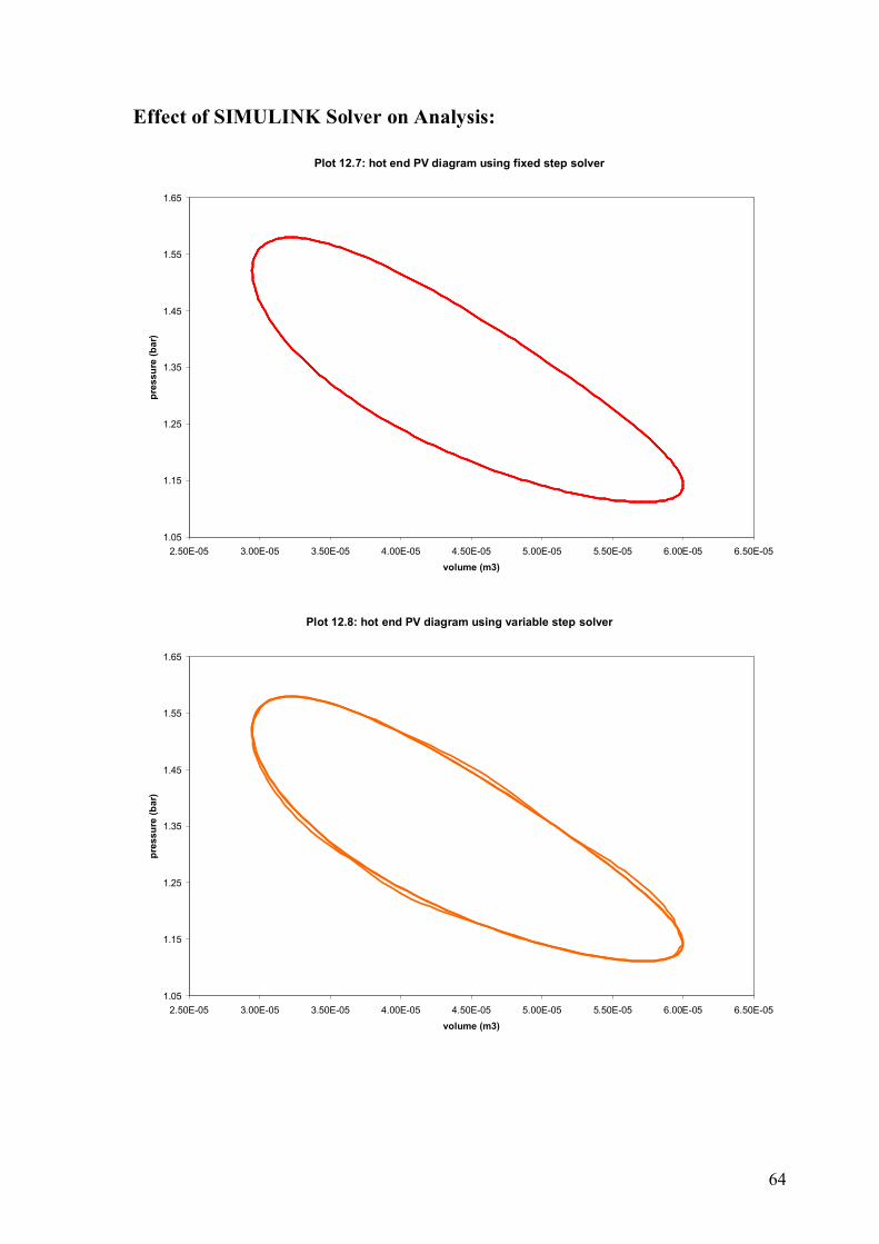
Effect of SIMULINK Solver on Analysis:

65
Plot 12.9: cold end PV diagram using fixed step solver
1.05
1.15
1.25
1.35
1.45
1.55
1.65
7.50E-06 9.50E-06 1.15E-05 1.35E-05 1.55E-05 1.75E-05 1.95E-05 2.15E-05 2.35E-05 2.55E-05volume (m3)
pres
sure
(bar
)
Plot 12.10: cold end PV diagram using variable step solver
1.05
1.15
1.25
1.35
1.45
1.55
1.65
7.50E-06 9.50E-06 1.15E-05 1.35E-05 1.55E-05 1.75E-05 1.95E-05 2.15E-05 2.35E-05 2.55E-05volume (m3)
pres
sure
(bar
)

66
The complete analysis is done using ODE3 (Bogacki – Shanpine) fixed step solver.
The fixed step size (fundamental sample time) is 0.01. The total sampling time was kept
fixed to 3 sec throughout the analysis. This gives a total of 301 data points.
Solving the same model with variable step solver (relative tolerance 1E-3) gives the
result similar to a real cycle as the P-V diagram is different from cycle to cycle. This is due
to the fact that, the same points in the model were solved for different step sizes from time
to time and the result is naturally different.

67
Section 4
Concluding Remarks

68
Discussion
The prototype and the simulation has the following limitations –
Cold End Response – Though the hot end of the prototype develops considerable thrust
producing about 180o rotation of the crank shaft, the cold end response of the system is not
strong enough to complete the cycle.
Slow Heating and Cooling of Working Gas – Effective running of the engine requires
quick heating and cooling of the working gas inside the hot and cold end respectively. This
is quite difficult to achieve due to lower thermal conductivity of working gas used i.e. air
and also due to the concentrated heat addition by gas burners used.
Side Leakage – At temperatures above 80oC, the hot end response reduces drastically. This
is mainly due to the fact that, at higher temperatures the increased pressure and thermal
expansion of the components increases the side leakage of the piston cylinder assembly.
Larger Dead Volume – As indicated by the simulation, smaller dead volumes result in
higher system pressure. It is more likely to achieve considerable power output at higher
system pressure. The larger dead volumes in the prototype are more responsible for lower
system pressure and slow response.
Weaker Flywheel – At the initial stage, the uncertainty about the hot end thrust and the
constraints in machining options tempted us to fabricate a much lighter and smaller
flywheel. In reality, the weaker flywheel couldn’t properly harness the hot end thrust to
recover lag in cold end response.
69
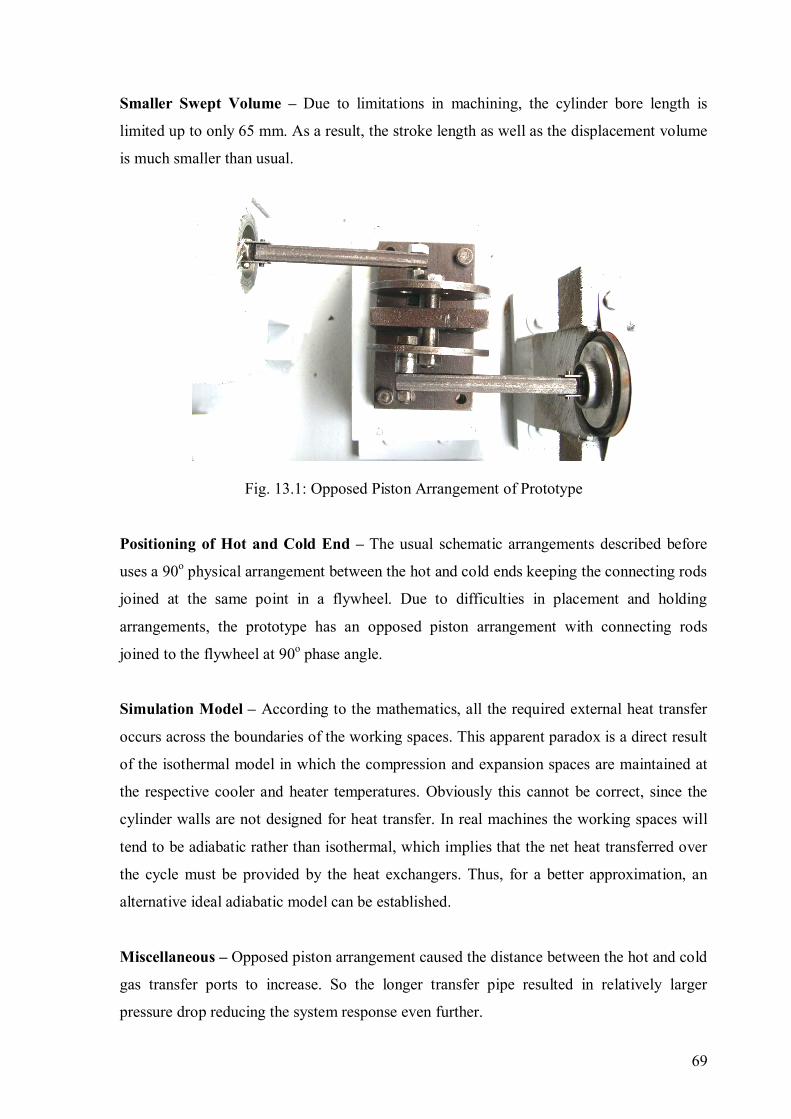
Smaller Swept Volume – Due to limitations in machining, the cylinder bore length is
limited up to only 65 mm. As a result, the stroke length as well as the displacement volume
is much smaller than usual.
Fig. 13.1: Opposed Piston Arrangement of Prototype
Positioning of Hot and Cold End – The usual schematic arrangements described before
uses a 90o physical arrangement between the hot and cold ends keeping the connecting rods
joined at the same point in a flywheel. Due to difficulties in placement and holding
arrangements, the prototype has an opposed piston arrangement with connecting rods
joined to the flywheel at 90o phase angle.
Simulation Model – According to the mathematics, all the required external heat transfer
occurs across the boundaries of the working spaces. This apparent paradox is a direct result
of the isothermal model in which the compression and expansion spaces are maintained at
the respective cooler and heater temperatures. Obviously this cannot be correct, since the
cylinder walls are not designed for heat transfer. In real machines the working spaces will
tend to be adiabatic rather than isothermal, which implies that the net heat transferred over
the cycle must be provided by the heat exchangers. Thus, for a better approximation, an
alternative ideal adiabatic model can be established.
Miscellaneous – Opposed piston arrangement caused the distance between the hot and cold
gas transfer ports to increase. So the longer transfer pipe resulted in relatively larger
pressure drop reducing the system response even further.

70
Conclusion
Fig. 14. 1: Alpha Stirling Prototype
Starting from theoretical thermodynamic analysis, a prototype of Stirling engine
was developed. But lack of desired response in the cold cylinder prompted us to develop a
computer simulation in order to identify the problems occurring inside the engine.
Comparing the results from the simulation with those from the experiment conducted, some
area of improvement was identified. We are very much hopeful that with the proposed
refinements, our successors will be able to run this prototype.

71
Recommendations
Incorporation of Quick Heating Arrangement:
Using a mesh type electric heater covering a larger surface area would reduce the
heating period and therefore increase the system response.
Redesigning the Flywheel:
A larger flywheel would surely assist in harnessing the hot end thrust to recover the
lag in cold end response.
Reduction in Dead Volume:
Dead volumes created in hot end should be reduced to increase system pressure.
Identical Hot and Cold End Dimensions:
From the SIMULINK Model, it is observed that identical hot and cold end
dimensions enable easier manipulation of system parameters which is not done in the
prototype.
Incorporation of a Regenerator:
In the prototype, a wire mesh is placed inside the hot end dead volume to work as a
regenerator. In further models, a regenerator with a better design and proper placement can
be used. Redesigning the regenerator would also require a minute change in the simulation
model.

72
Initial Pressurization:
To increase the power density, initially pressurized systems as stated in chapter five
can be used.
Working Gas:
Modern Stirling engines use working fluids like helium, hydrogen etc. to utilize
their higher thermal conductivity rather than using air. In further working models, this
concept can also be used.
Insulation of Gas Transfer Arrangement:
The transfer arrangement can be insulated to reduce heat loss during gas transfer.

73
References
Books & Review Papers –
1. Engineering Thermodynamics: Rogers, G., Matthew Y. (Pearson Education)
2. Fundamentals of Stirling Technology: Walker, Fauvel, R.
3. An Introduction to LTD Stirling Engines: Senft, James R. (Moriya Press)
4. Build a Two Cylinder Stirling Cycle Engine: Gingery, David J. (Library of
Congress)
5. Stirling and Hot Air Engines: Press, C.
6. The Evolution of the Heat Engine: Kolin, I.
7. Thermodynamics and Gas Dynamics of the Stirling Cycle Machine: Organ, Allan J.
8. Thermodynamic Analysis of the Stirling cycle machine – a review of the literature:
Organ, Allan J. (IMechE 1987)
9. A user friendly graphics oriented Stirling engine simulation program: Weiss, M.,
Fauvel, R. (ISEC 1986)
Internet Resources –
1. http://www.stirlingengine.com/
2. http://www.keveney.com/Engines.html
3. http://www.ent.ohiou.edu/~urieli/stirling/me422.html
4. http://www.cse.iitk.ac.in/~amit/courses/371/abhishe/main.html
5. http://engine.stirling.cz/tedom-stirling-engine-history.html
6. http://en.wikipedia.org/wiki/Stirling_engine

74
Appendix
Detailed Drawings of the Prototype
Fig. 17.1: Hot End Cylinder
Fig. 17.2: Hot End Assembly

75
Fig. 17.3: Cold End Cylinder
Fig. 17.4: Cold End Assembly

76
Fig. 17.5: Cold End Piston
Fig. 17.6: Hot End Piston

77
Fig. 17.7: Connecting Rod Assembly
Fig. 17.8: Crank & Flywheel Assembly (Front View)

78
Fig. 17.9: Crank & Flywheel Assembly (Side View)
Fig. 17.10: Crank & Flywheel Assembly (Top View)

79
Fig. 17.11: Engine Assembly
Fig. 17.12: Engine Assembly with Base and Holder


![WELCOME [teacher.buet.ac.bd]teacher.buet.ac.bd/ziawadud/documents/seraj.pdf · welcome to the presentation on ... typical sheltech organogram of construction management. may 24,](https://img.pdfslide.us/doc/110x75/5a858de47f8b9ad30c8c768a/welcome-to-the-presentation-on-typical-sheltech-organogram-of-construction.jpg)


![[XLS]obcindia.co.inobcindia.co.in/obcnew/upload/obc/Unpaid Dividend 2013-14... · Web view400 400 400 400 400 400 400 400 400 400 400 400 400 400 400 400 400 400 400 400 400 400 400](https://img.pdfslide.us/doc/110x75/5aa6f94e7f8b9a54748b6a16/xls-dividend-2013-14web-view400-400-400-400-400-400-400-400-400-400-400-400.jpg)