Embed Size (px)
Citation preview
ME 322: InstrumentationLecture 12
February 13, 2015
Professor Miles Greiner
Flow rate devices, variable area, non-linear transfer function, standards, iterative method
Announcement/Reminders• HW 4 due now (please staple)• Monday – Holiday• Wednesday – HW 5 due and review for Midterm• Friday, Feb. 20, 2016 Midterm
• How was lab yesterday and the day before?– Trouble bonding stain gages to beams?– Access to glue?
• We will purchase one more pressure standard and more glue before next year’s class.
Fluid Flow Rates
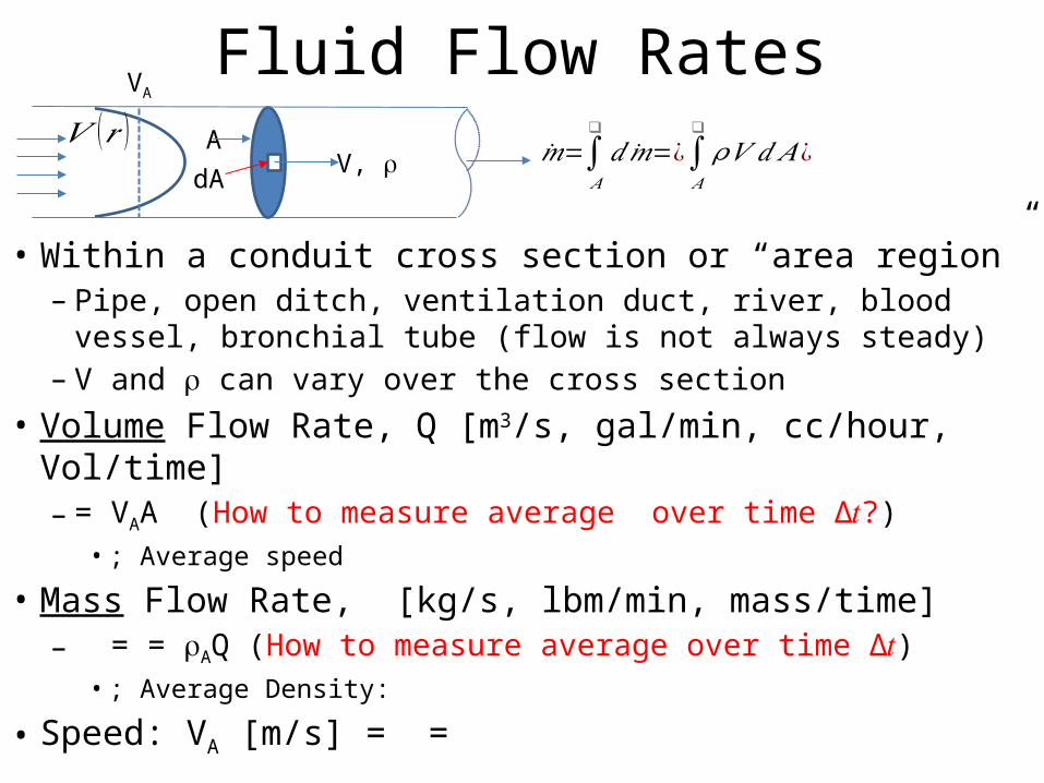
• Within a conduit cross section or “area region”– Pipe, open ditch, ventilation duct, river, blood vessel, bronchial
tube (flow is not always steady)– V and r can vary over the cross section
• Volume Flow Rate, Q [m3/s, gal/min, cc/hour, Vol/time]– = VAA (How to measure average over time Δ𝑡?)
• ; Average speed
• Mass Flow Rate, [kg/s, lbm/min, mass/time]– = = rAQ (How to measure average over time Δ𝑡)
• ; Average Density:
• Speed: VA [m/s] = =
�̇�=∫𝐴
❑
𝑑�̇�=¿∫𝐴
❑
𝜌𝑉 𝑑 𝐴¿A
dAV, r
VA
𝑉 (𝑟 )
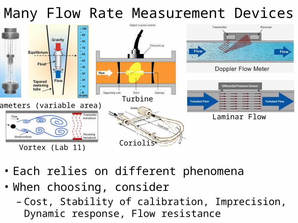
Many Flow Rate Measurement Devices
• Each relies on different phenomena • When choosing, consider – Cost, Stability of calibration, Imprecision, Dynamic response,
Flow resistance
Rotameters (variable area)Turbine
Vortex (Lab 11)
Laminar Flow
Coriolis
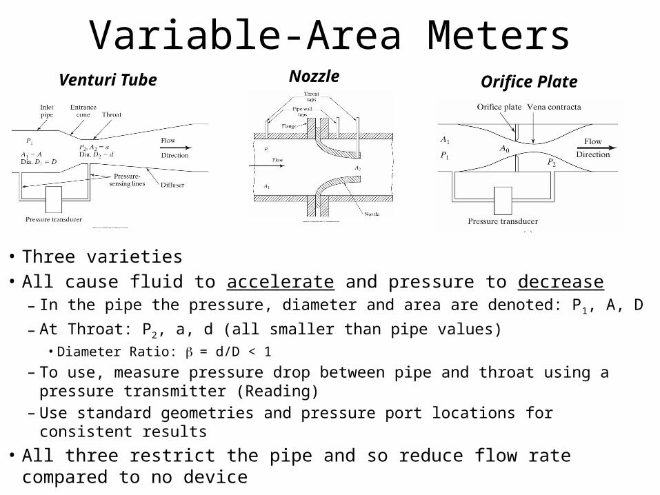
Variable-Area Meters
• Three varieties• All cause fluid to accelerate and pressure to decrease
– In the pipe the pressure, diameter and area are denoted: P1, A, D
– At Throat: P2, a, d (all smaller than pipe values)• Diameter Ratio: b = d/D < 1
– To use, measure pressure drop between pipe and throat using a pressure transmitter (Reading)
– Use standard geometries and pressure port locations for consistent results
• All three restrict the pipe and so reduce flow rate compared to no device
Venturi Tube Nozzle Orifice Plate
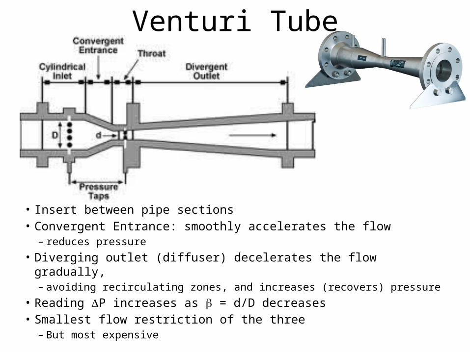
Venturi Tube
• Insert between pipe sections• Convergent Entrance: smoothly accelerates the flow
– reduces pressure
• Diverging outlet (diffuser) decelerates the flow gradually, – avoiding recirculating zones, and increases (recovers) pressure
• Reading DP increases as b = d/D decreases• Smallest flow restriction of the three
– But most expensive
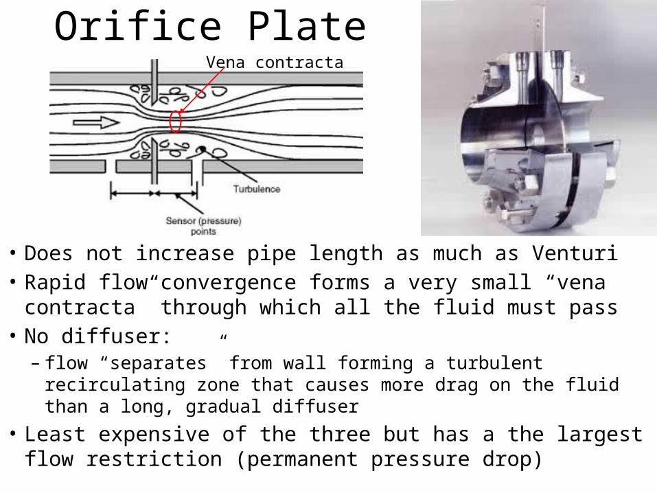
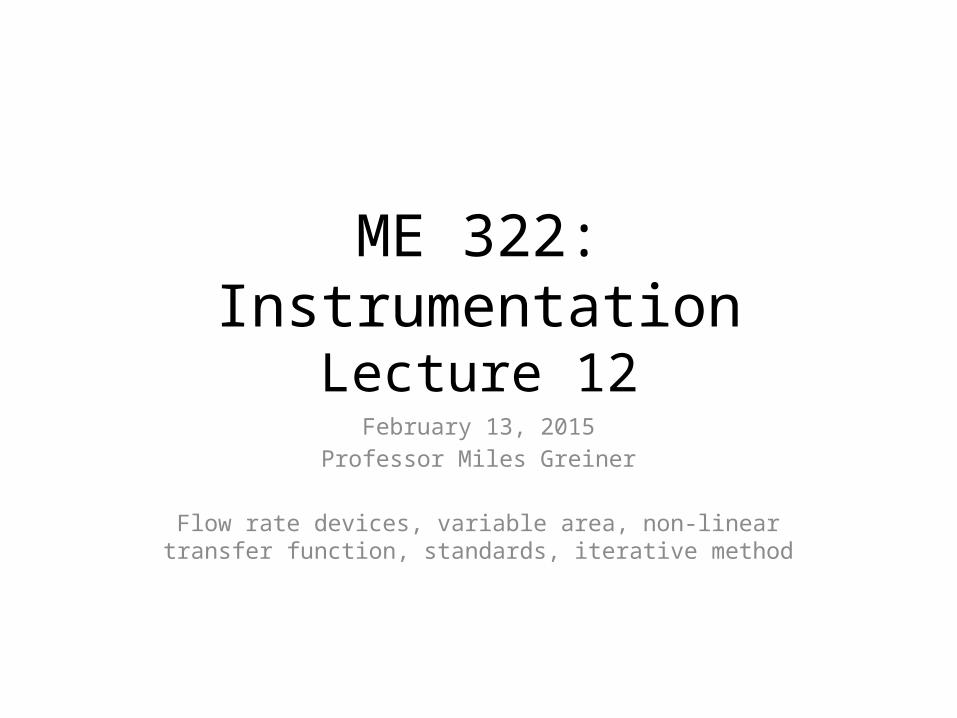
Orifice Plate
• Does not increase pipe length as much as Venturi• Rapid flow convergence forms a very small “vena
contracta” through which all the fluid must pass• No diffuser:
– flow “separates” from wall forming a turbulent recirculating zone that causes more drag on the fluid than a long, gradual diffuser
• Least expensive of the three but has a the largest flow restriction (permanent pressure drop)
Vena contracta
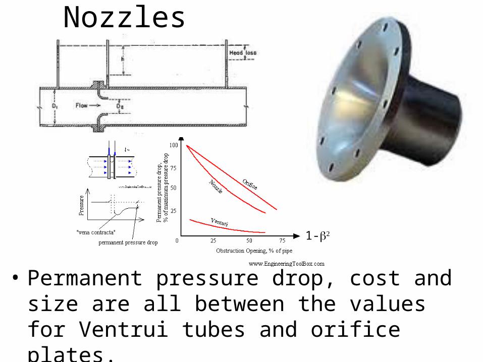
Nozzles
• Permanent pressure drop, cost and size are all between the values for Ventrui tubes and orifice plates.
1-b2
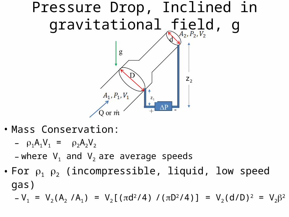
Pressure Drop, Inclined in gravitational field, g
• Mass Conservation: – r1A1V1 = r2A2V2
– where V1 and V2 are average speeds
• For r1 r2 (incompressible, liquid, low speed gas)
– V1 = V2(A2 /A1) = V2[(pd2/4) /(pD2/4)] = V2(d/D)2 = V2b2
z2
z1
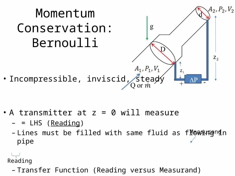
Momentum Conservation: Bernoulli
• Incompressible, inviscid, steady • A transmitter at z = 0 will measure
– = LHS (Reading)– Lines must be filled with same fluid as flowing in pipe
– Transfer Function (Reading versus Measurand)
Reading
Measurand
z2
z1
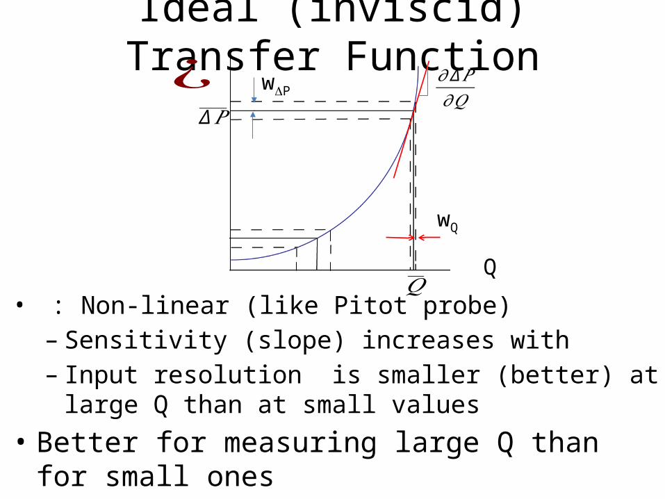
Ideal (inviscid) Transfer Function
• : Non-linear (like Pitot probe)– Sensitivity (slope) increases with – Input resolution is smaller (better) at large Q than at
small values
• Better for measuring large Q than for small ones
Q
¿∆𝑃
𝑄
wDP
wQ
𝜕∆𝑃𝜕𝑄
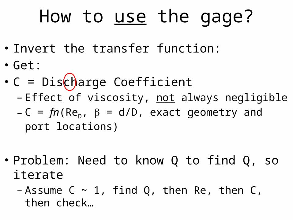
How to use the gage?
• Invert the transfer function: • Get: • C = Discharge Coefficient – Effect of viscosity, not always negligible
– C = fn(ReD, b = d/D, exact geometry and port locations)
• Problem: Need to know Q to find Q, so iterate– Assume C ~ 1, find Q, then Re, then C, then check…
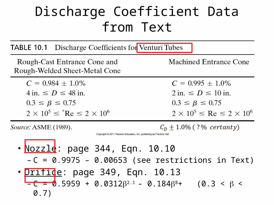
Discharge Coefficient Data from Text
• Nozzle: page 344, Eqn. 10.10– C = 0.9975 – 0.00653 (see restrictions in Text)
• Orifice: page 349, Eqn. 10.13– C = 0.5959 + 0.0312b2.1 - 0.184b8+ (0.3 < b < 0.7)
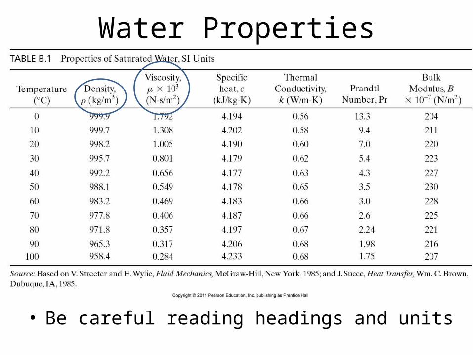
Water Properties
• Be careful reading headings and units
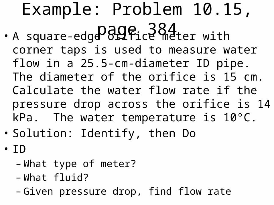
Example: Problem 10.15, page 384• A square-edge orifice meter with corner taps is used
to measure water flow in a 25.5-cm-diameter ID pipe. The diameter of the orifice is 15 cm. Calculate the water flow rate if the pressure drop across the orifice is 14 kPa. The water temperature is 10°C.
• Solution: Identify, then Do• ID–What type of meter?–What fluid?– Given pressure drop, find flow rate
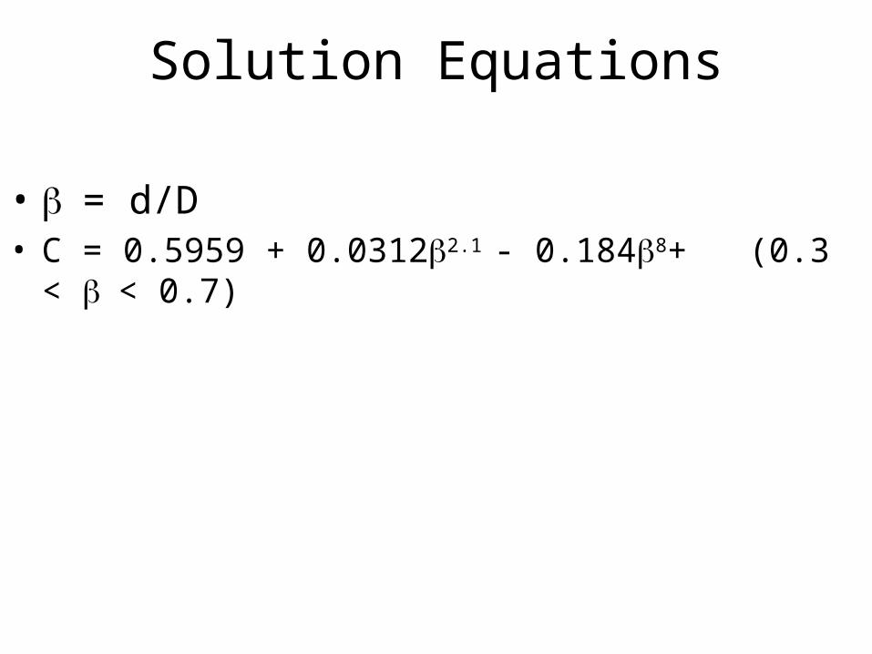
Solution Equations
• b = d/D• C = 0.5959 + 0.0312b2.1 - 0.184b8+ (0.3 < b < 0.7)