Embed Size (px)
Citation preview

MD10V 21/28
MANUALE DELL’OPERATORE
OPERATOR MANUAL
Cod. 05-0028-A05

Pag. 2/16
REGOLATORE MANUALE A LEVA RETROAZIONATO MANUAL LEVER WITH FEED-BACK CONTROL
(HLR)
METRICA METRIC SAE
A, B Utilizzi Pressure Ports 3/4 G (BSPP) 7/8 - 14 UNF - 2B
D1, D2 Drenaggi Drain Port 1/2 G (BSPP) 3/4 - 16 UNF - 2B
S Aspirazione Suction Port 3/4 G (BSPP) 1 1/16 - 12 UN - 2B
P Attacco pressione sovralimentazione Boost pressure gauge port 3/4 - 16 UNF - 2B 3/4 - 16 UNF - 2B
Va Valvola di alimentazione Boost pressure relief valve
Ch. 13 Es inc 4 13 Locking nut - Allen key 4
Ch. 13 Es inc 4 13 Locking nut - Allen key 4
V1, V2 Valvole di massima Pressure Relief Valve
Es inc 10 Allen key 10
Es inc 10 Allen key 10
Zm Vite azzeratore meccanico Mechanical zero adjustment
Ch. 13 Es inc 4 13 Locking nut - Allen key 4
Ch. 13 Es inc 4 13 Locking nut - Allen key 4
Sl 1 Limitatore di cilindrata Displacement Limiter
Ch. 10 Es inc 3 10 Locking nut - Allen key 3
Ch. 10 Es inc 3 10 Locking nut - Allen key 3
Sl 2 Limitatore di cilindrata Displacement Limiter
Ch. 13 Es inc 4 13 Locking nut - Allen key 4
Ch. 13 Es inc 4 13 Locking nut - Allen key 4
Bp Bypass Bypass
Ch. 14 14 Locking nut
Ch. 14 14 Locking nut
LEGENDA LEGEND

Pag. 3/16
SCHEMA IDRAULICO (HLR) HYDRAULIC LAYOUT (HLR)
REGOLAZIONE ZERO MECCANICO Svitare con la chiave di 13 il dado di tenuta, agire poi ruotando il grano (chiave a brugola di 4 mm) in senso orario o antiorario finché la pompa non si porta in posizione neutra, serrare nuo-vamente il dado di tenuta.
REGOLAZIONE DELLA CILINDRATA MASSIMA Svitare con la chiave di 13 o 10 il dado di tenuta, ruotare in senso orario (riduzione cilindrata) o in senso antiorario (aumento cilindrata) il grano di fine corsa (chiave a brugola di 4 o 3 mm), serrare nuovamente il dado di tenuta. Gruppo rotante 21 cc - grano SI1 1.6 c.c./rev. grano SI2 1.95 c.c./rev. Gruppo rotante 28 cc - grano SI1 2 c.c./rev. grano SI2 2.6 c.c./rev.
REGOLAZIONE PRESSIONE DI ALIMENTAZIONE Svitare con la chiave di 13 il dado di tenuta, ruotare in senso orario (aumento pressione) o in senso antiorario (diminuzione pressione) il grano di regolazione (chiave a brugola di 4 mm), serrare nuovamente il dado di tenuta. Un giro completo com-porta una variazione approssimativa di 5 bar.
MECHANICAL ZERO ADJUSTMENT Unscrew with a 13 spanner the locking nut, then rotate the grub screw (Allen key 4 mm) clockwise or anticlockwise until the pump is centered., then tighten again the locking nut.
MAXIMUM DISPLACEMENT SETTING Unscrew with a 13 or 10 spanner the locking nut, rotate clo-ckwise (Displacement decreases) or anticlockwise (Displacement increases) the grub screw (Allen key 4 or 3 mm), tighten again the locking nut. Rotating Group 21 cc - grub screw SI1 1.6 c.c./rev. grub screw SI2 1.95 c.c./rev. Rotating Group 28 cc - grub screw SI1 2 c.c./rev. grub screw SI2 2.6 c.c./rev.
PRESSURE SETTING Unscrew with a 13 spanner the locking nut, rotate clockwise (Pressure increases) or anticlockwise (Pressure decreases) the setting grub screw (Allen key 4 mm), tighten again locking nut. (5 bar/rev).
Rotazione albero Shaft rotation
Rotazione comando Control rotation
Mandata olio da Oil outlet
SINISTRO (CCW)
1 A
2 B
DESTRO (CW)
1 B
2 A
Direzione portata pompa Pump flow direction
SENSO DI ROTAZIONE/DIRECTION OF ROTATION

Pag. 4/16
REGOLATORE IDRAULICO PROPORZIONALE RETROAZIONATO HYDRAULIC PROPORTIONAL WITH FEED-BACK CONTROL
(HIR)
METRICA METRIC SAE
A, B Utilizzi Pressure Ports 3/4 G (BSPP) 7/8 - 14 UNF - 2B
D1, D2 Drenaggi Drain Port 1/2 G (BSPP) 3/4 - 16 UNF - 2B
S Aspirazione Suction Port 3/4 G (BSPP) 1 1/16 - 12 UN - 2B
P Attacco pressione sovralimentazione Boost pressure gauge port 3/4 - 16 UNF - 2B 3/4 - 16 UNF - 2B
Va Valvola di alimentazione Boost pressure relief valve
Ch. 13 Es inc 4 13 Locking nut - Allen key 4
Ch. 13 Es inc 4 13 Locking nut - Allen key 4
V1, V2 Valvole di massima Pressure Relief Valve
Es inc 10 Allen key 10
Es inc 10 Allen key 10
Zm Vite azzeratore meccanico Mechanical zero adjustment
Ch. 13 Es inc 4 13 Locking nut - Allen key 4
Ch. 13 Es inc 4 13 Locking nut - Allen key 4
Sl 1 Limitatore di cilindrata Displacement Limiter
Ch. 10 Es inc 3 10 Locking nut - Allen key 3
Ch. 10 Es inc 3 10 Locking nut - Allen key 3
Sl 2 Limitatore di cilindrata Displacement Limiter
Ch. 13 Es inc 4 13 Locking nut - Allen key 4
Ch. 13 Es inc 4 13 Locking nut - Allen key 4
Bp Bypass Bypass
Ch. 14 14 Locking nut
Ch. 14 14 Locking nut
LEGENDA LEGEND
Zi Vite azzeratore idraulico Hydraulic zero adjustment
Ch. 10 Es inc 3 10 Locking nut - Allen key 3
Ch. 10 Es inc 3 10 Locking nut - Allen key 3
a, b Attacchi per pilotaggio comando Control piloting pressure ports 1/8 G (BSPP) 5/16 - 24 UNF - 2B
Pag. 5/16
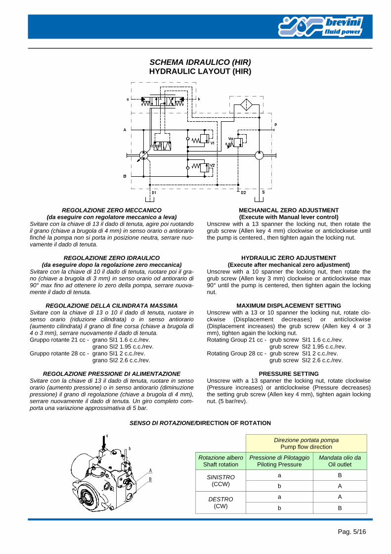
SCHEMA IDRAULICO (HIR) HYDRAULIC LAYOUT (HIR)
Rotazione albero Shaft rotation
Pressione di Pilotaggio Piloting Pressure
Mandata olio da Oil outlet
SINISTRO (CCW)
a B
b A
DESTRO (CW)
a A
b B
Direzione portata pompa Pump flow direction
MECHANICAL ZERO ADJUSTMENT (Execute with Manual lever control)
Unscrew with a 13 spanner the locking nut, then rotate the grub screw (Allen key 4 mm) clockwise or anticlockwise until the pump is centered., then tighten again the locking nut.
HYDRAULIC ZERO ADJUSTMENT (Execute after mechanical zero adjustment)
Unscrew with a 10 spanner the locking nut, then rotate the grub screw (Allen key 3 mm) clockwise or anticlockwise max 90° until the pump is centered, then tighten again the locking nut.
MAXIMUM DISPLACEMENT SETTING Unscrew with a 13 or 10 spanner the locking nut, rotate clo-ckwise (Displacement decreases) or anticlockwise (Displacement increases) the grub screw (Allen key 4 or 3 mm), tighten again the locking nut. Rotating Group 21 cc - grub screw SI1 1.6 c.c./rev. grub screw SI2 1.95 c.c./rev. Rotating Group 28 cc - grub screw SI1 2 c.c./rev. grub screw SI2 2.6 c.c./rev.
PRESSURE SETTING Unscrew with a 13 spanner the locking nut, rotate clockwise (Pressure increases) or anticlockwise (Pressure decreases) the setting grub screw (Allen key 4 mm), tighten again locking nut. (5 bar/rev).
SENSO DI ROTAZIONE/DIRECTION OF ROTATION
REGOLAZIONE ZERO MECCANICO (da eseguire con regolatore meccanico a leva)
Svitare con la chiave di 13 il dado di tenuta, agire poi ruotando il grano (chiave a brugola di 4 mm) in senso orario o antiorario finché la pompa non si porta in posizione neutra, serrare nuo-vamente il dado di tenuta.
REGOLAZIONE ZERO IDRAULICO (da eseguire dopo la regolazione zero meccanica)
Svitare con la chiave di 10 il dado di tenuta, ruotare poi il gra-no (chiave a brugola di 3 mm) in senso orario od antiorario di 90° max fino ad ottenere lo zero della pompa, serrare nuova-mente il dado di tenuta.
REGOLAZIONE DELLA CILINDRATA MASSIMA Svitare con la chiave di 13 o 10 il dado di tenuta, ruotare in senso orario (riduzione cilindrata) o in senso antiorario (aumento cilindrata) il grano di fine corsa (chiave a brugola di 4 o 3 mm), serrare nuovamente il dado di tenuta. Gruppo rotante 21 cc - grano SI1 1.6 c.c./rev. grano SI2 1.95 c.c./rev. Gruppo rotante 28 cc - grano SI1 2 c.c./rev. grano SI2 2.6 c.c./rev.
REGOLAZIONE PRESSIONE DI ALIMENTAZIONE Svitare con la chiave di 13 il dado di tenuta, ruotare in senso orario (aumento pressione) o in senso antiorario (diminuzione pressione) il grano di regolazione (chiave a brugola di 4 mm), serrare nuovamente il dado di tenuta. Un giro completo com-porta una variazione approssimativa di 5 bar.

Pag. 6/16
REGOLATORE IDRAULICO PROPORZIONALE NON RETROAZIONATO HYDRAULIC PROPORTIONAL WITHOUT FEED-BACK CONTROL
(HIN) Fuori produzione da fine febbraio 2008
Out of production from end of February 2008
LEGENDA LEGEND
METRICA METRIC SAE
A, B Utilizzi Pressure Ports 3/4 G (BSPP) 7/8 - 14 UNF - 2B
D1, D2 Drenaggi Drain Port 1/2 G (BSPP) 3/4 - 16 UNF - 2B
S Aspirazione Suction Port 3/4 G (BSPP) 1 1/16 - 12 UN - 2B
P Attacco pressione sovralimentazione Boost pressure gauge port 3/4 - 16 UNF - 2B 3/4 - 16 UNF - 2B
Va Valvola di alimentazione Boost pressure relief valve
Ch. 13 Es inc 4 13 Locking nut - Allen key 4
Ch. 13 Es inc 4 13 Locking nut - Allen key 4
V1, V2 Valvole di massima Pressure Relief Valve
Es inc 10 Allen key 10
Es inc 10 Allen key 10
Zm Vite azzeratore meccanico Mechanical zero adjustment
Ch. 13 Es inc 4 13 Locking nut - Allen key 4
Ch. 13 Es inc 4 13 Locking nut - Allen key 4
Sl 1 Limitatore di cilindrata Displacement Limiter
Ch. 10 Es inc 3 10 Locking nut - Allen key 3
Ch. 10 Es inc 3 10 Locking nut - Allen key 3
Sl 2 Limitatore di cilindrata Displacement Limiter
Ch. 13 Es inc 4 13 Locking nut - Allen key 4
Ch. 13 Es inc 4 13 Locking nut - Allen key 4
a, b Attacchi per pilotaggio comando Control piloting pressure ports 1/4 G (BSPP) 7/16 - 20 UNF - 2B
Bp Bypass Bypass
Ch. 14 14 Locking nut
Ch. 14 14 Locking nut
p Attacco pressione alimentazione Pressure gauge ports 1/4 G (BSPP) 7/16 - 20 UNF - 2B

Pag. 7/16
SCHEMA IDRAULICO (HIN) HYDRAULIC LAYOUT (HIN)
REGOLAZIONE ZERO MECCANICO Svitare con la chiave di 13 il dado di tenuta, agire poi ruotando il grano (chiave a brugola di 4 mm) in senso orario o antiorario finché la pompa non si porta in posizione neutra, serrare nuo-vamente il dado di tenuta.
REGOLAZIONE DELLA CILINDRATA MASSIMA Svitare con la chiave di 13 o 10 il dado di tenuta, ruotare in senso orario (riduzione cilindrata) o in senso antiorario (aumento cilindrata) il grano di fine corsa (chiave a brugola di 4 o 3 mm), serrare nuovamente il dado di tenuta. Gruppo rotante 21 cc - grano SI1 1.6 c.c./rev. grano SI2 1.95 c.c./rev. Gruppo rotante 28 cc - grano SI1 2 c.c./rev. grano SI2 2.6 c.c./rev.
REGOLAZIONE PRESSIONE DI ALIMENTAZIONE Svitare con la chiave di 13 il dado di tenuta, ruotare in senso orario (aumento pressione) o in senso antiorario (diminuzione pressione) il grano di regolazione (chiave a brugola di 4 mm), serrare nuovamente il dado di tenuta. Un giro completo com-porta una variazione approssimativa di 5 bar.
MECHANICAL ZERO ADJUSTMENT Unscrew with a 13 spanner the locking nut, then rotate the grub screw (Allen key 4 mm) clockwise or anticlockwise until the pump is centered., then tighten again the locking nut.
MAXIMUM DISPLACEMENT SETTING Unscrew with a 13 or 10 spanner the locking nut, rotate clo-ckwise (Displacement decreases) or anticlockwise (Displacement increases) the grub screw (Allen key 4 or 3 mm), tighten again the locking nut. Rotating Group 21 cc - grub screw SI1 1.6 c.c./rev. grub screw SI2 1.95 c.c./rev. Rotating Group 28 cc - grub screw SI1 2 c.c./rev. grub screw SI2 2.6 c.c./rev.
PRESSURE SETTING Unscrew with a 13 spanner the locking nut, rotate clockwise (Pressure increases) or anticlockwise (Pressure decreases) the setting grub screw (Allen key 4 mm), tighten again locking nut. (5 bar/rev).
Rotazione albero Shaft rotation
Pressione di Pilotaggio Piloting Pressure
Mandata olio da Oil outlet
SINISTRO (CCW)
a A
b B
DESTRO (CW)
a B
b A
Direzione portata pompa Pump flow direction
SENSO DI ROTAZIONE/DIRECTION OF ROTATION

Pag. 8/16
REGOLATORE IDRAULICO PROPORZIONALE NON RETROAZIONATO HYDRAULIC PROPORTIONAL WITHOUT FEED-BACK CONTROL
(HIN) Nuova versione
New version
LEGENDA LEGEND
METRICA METRIC SAE
A, B Utilizzi Pressure Ports 3/4 G (BSPP) 7/8 - 14 UNF - 2B
D1, D2 Drenaggi Drain Port 1/2 G (BSPP) 3/4 - 16 UNF - 2B
S Aspirazione Suction Port 3/4 G (BSPP) 1 1/16 - 12 UN - 2B
P Attacco pressione sovralimentazione Boost pressure gauge port 3/4 - 16 UNF - 2B 3/4 - 16 UNF - 2B
Va Valvola di alimentazione Boost pressure relief valve
Ch. 13 Es inc 4 13 Locking nut - Allen key 4
Ch. 13 Es inc 4 13 Locking nut - Allen key 4
V1, V2 Valvole di massima Pressure Relief Valve
Es inc 10 Allen key 10
Es inc 10 Allen key 10
Zm Vite azzeratore meccanico Mechanical zero adjustment
Ch. 13 Es inc 4 13 Locking nut - Allen key 4
Ch. 13 Es inc 4 13 Locking nut - Allen key 4
Sl 1 Limitatore di cilindrata Displacement Limiter
Ch. 10 Es inc 3 10 Locking nut - Allen key 3
Ch. 10 Es inc 3 10 Locking nut - Allen key 3
Sl 2 Limitatore di cilindrata Displacement Limiter
Ch. 13 Es inc 4 13 Locking nut - Allen key 4
Ch. 13 Es inc 4 13 Locking nut - Allen key 4
a, b Attacchi per pilotaggio comando Control piloting pressure ports 1/8 G (BSPP) 7/16 - 20 UNF - 2B
Bp Bypass Bypass
Ch. 14 14 Locking nut
Ch. 14 14 Locking nut
p Attacco pressione alimentazione Pressure gauge ports 1/8 G (BSPP) 7/16 - 20 UNF - 2B

Pag. 9/16
SCHEMA IDRAULICO (HIN) HYDRAULIC LAYOUT (HIN)
REGOLAZIONE ZERO MECCANICO Svitare con la chiave di 13 il dado di tenuta, agire poi ruotando il grano (chiave a brugola di 4 mm) in senso orario o antiorario finché la pompa non si porta in posizione neutra, serrare nuo-vamente il dado di tenuta.
REGOLAZIONE DELLA CILINDRATA MASSIMA Svitare con la chiave di 13 o 10 il dado di tenuta, ruotare in senso orario (riduzione cilindrata) o in senso antiorario (aumento cilindrata) il grano di fine corsa (chiave a brugola di 4 o 3 mm), serrare nuovamente il dado di tenuta. Gruppo rotante 21 cc - grano SI1 1.6 c.c./rev. grano SI2 1.95 c.c./rev. Gruppo rotante 28 cc - grano SI1 2 c.c./rev. grano SI2 2.6 c.c./rev.
REGOLAZIONE PRESSIONE DI ALIMENTAZIONE Svitare con la chiave di 13 il dado di tenuta, ruotare in senso orario (aumento pressione) o in senso antiorario (diminuzione pressione) il grano di regolazione (chiave a brugola di 4 mm), serrare nuovamente il dado di tenuta. Un giro completo com-porta una variazione approssimativa di 5 bar.
MECHANICAL ZERO ADJUSTMENT Unscrew with a 13 spanner the locking nut, then rotate the grub screw (Allen key 4 mm) clockwise or anticlockwise until the pump is centered., then tighten again the locking nut.
MAXIMUM DISPLACEMENT SETTING Unscrew with a 13 or 10 spanner the locking nut, rotate clo-ckwise (Displacement decreases) or anticlockwise (Displacement increases) the grub screw (Allen key 4 or 3 mm), tighten again the locking nut. Rotating Group 21 cc - grub screw SI1 1.6 c.c./rev. grub screw SI2 1.95 c.c./rev. Rotating Group 28 cc - grub screw SI1 2 c.c./rev. grub screw SI2 2.6 c.c./rev.
PRESSURE SETTING Unscrew with a 13 spanner the locking nut, rotate clockwise (Pressure increases) or anticlockwise (Pressure decreases) the setting grub screw (Allen key 4 mm), tighten again locking nut. (5 bar/rev).
Rotazione albero Shaft rotation
Pressione di Pilotaggio Piloting Pressure
Mandata olio da Oil outlet
SINISTRO (CCW)
a A
b B
DESTRO (CW)
a B
b A
Direzione portata pompa Pump flow direction
SENSO DI ROTAZIONE/DIRECTION OF ROTATION

Pag. 10/16
REGOLATORE ELETTROMAGNETICO PROPORZIONALE RETROAZIONATO ELECTRIC PROPORTIONAL WITH FEED-BACK CONTROL
(HER)
LEGENDA LEGEND
METRICA METRIC SAE
A, B Utilizzi Pressure Ports 3/4 G (BSPP) 7/8 - 14 UNF - 2B
D1, D2 Drenaggi Drain Port 1/2 G (BSPP) 3/4 - 16 UNF - 2B
S Aspirazione Suction Port 3/4 G (BSPP) 1 1/16 - 12 UN - 2B
P Attacco pressione sovralimentazione Boost pressure gauge port 3/4 - 16 UNF - 2B 3/4 - 16 UNF - 2B
Va Valvola di alimentazione Boost pressure relief valve
Ch. 13 Es inc 4 13 Locking nut - Allen key 4
Ch. 13 Es inc 4 13 Locking nut - Allen key 4
V1, V2 Valvole di massima Pressure Relief Valve
Es inc 10 Allen key 10
Es inc 10 Allen key 10
Zm Vite azzeratore meccanico Mechanical zero adjustment
Ch. 13 Es inc 4 13 Locking nut - Allen key 4
Ch. 13 Es inc 4 13 Locking nut - Allen key 4
Zi Vite azzeratore idraulico Hydraulic zero adjustment
Ch. 10 Es inc 3 10 Locking nut - Allen key 3
Ch. 10 Es inc 3 10 Locking nut - Allen key 3
Sl 1 Limitatore di cilindrata Displacement Limiter
Ch. 10 Es inc 3 10 Locking nut - Allen key 3
Ch. 10 Es inc 3 10 Locking nut - Allen key 3
Sl 2 Limitatore di cilindrata Displacement Limiter
Ch. 13 Es inc 4 13 Locking nut - Allen key 4
Ch. 13 Es inc 4 13 Locking nut - Allen key 4
1, 2 Solenoidi proporzionali Proportional Solenoid Valves
Connettore DIN 43650A Connector DIN 43650A
Connettore DIN 43650A Connector DIN 43650A
Bp Bypass Bypass
Ch. 14 14 Locking nut
Ch. 14 14 Locking nut

Pag. 11/16
SCHEMA IDRAULICO (HER) HYDRAULIC LAYOUT (HER)
Rotazione albero Shaft rotation
Alimentazione Magnete Energized Solenoid
Mandata olio da Oil outlet
SINISTRO (CCW)
1 B
2 A
DESTRO (CW)
1 A
2 B
Direzione portata pompa Pump flow direction
MECHANICAL ZERO ADJUSTMENT (Execute with Manual lever control)
Unscrew with a 13 spanner the locking nut, then rotate the grub screw (Allen key 4 mm) clockwise or anticlockwise until the pump is centered., then tighten again the locking nut.
HYDRAULIC ZERO ADJUSTMENT (Execute after mechanical zero adjustment)
Unscrew with a 10 spanner the locking nut, then rotate the grub screw (Allen key 3 mm) clockwise or anticlockwise max 90° until the pump is centered, then tighten again the locking nut.
MAXIMUM DISPLACEMENT SETTING Unscrew with a 13 or 10 spanner the locking nut, rotate clo-ckwise (Displacement decreases) or anticlockwise (Displacement increases) the grub screw (Allen key 4 o 3 mm), tighten again the locking nut. Rotating Group 21 cc - grub screw SI1 1.6 c.c./rev. grub screw SI2 1.95 c.c./rev. Rotating Group 28 cc - grub screw SI1 2 c.c./rev. grub screw SI2 2.6 c.c./rev.
PRESSURE SETTING Unscrew with a 13 spanner the locking nut, rotate clockwise (Pressure increases) or anticlockwise (Pressure decreases) the setting grub screw (Allen key 4 mm), tighten again locking nut. (5 bar/rev).
REGOLAZIONE ZERO MECCANICO (da eseguire con regolatore meccanico a leva)
Svitare con la chiave di 13 il dado di tenuta, agire poi ruotando il grano (chiave a brugola di 4 mm) in senso orario o antiorario finché la pompa non si porta in posizione neutra, serrare nuo-vamente il dado di tenuta.
REGOLAZIONE ZERO IDRAULICO (da eseguire dopo la regolazione zero meccanica)
Svitare con la chiave di 10 il dado di tenuta, ruotare poi il gra-no (chiave a brugola di 3 mm) in senso orario od antiorario di 90° max fino ad ottenere lo zero della pompa, serrare nuova-mente il dado di tenuta.
REGOLAZIONE DELLA CILINDRATA MASSIMA Svitare con la chiave di 13 o 10 il dado di tenuta, ruotare in senso orario (riduzione cilindrata) o in senso antiorario (aumento cilindrata) il grano di fine corsa (chiave a brugola di 4 o 3 mm), serrare nuovamente il dado di tenuta. Gruppo rotante 21 cc - grano SI1 1.6 c.c./rev. grano SI2 1.95 c.c./rev. Gruppo rotante 28 cc - grano SI1 2 c.c./rev. grano SI2 2.6 c.c./rev.
REGOLAZIONE PRESSIONE DI ALIMENTAZIONE Svitare con la chiave di 13 il dado di tenuta, ruotare in senso orario (aumento pressione) o in senso antiorario (diminuzione pressione) il grano di regolazione (chiave a brugola di 4 mm), serrare nuovamente il dado di tenuta. Un giro completo com-porta una variazione approssimativa di 5 bar.
SENSO DI ROTAZIONE/DIRECTION OF ROTATION

Pag. 12/16
REGOLATORE ELETTROMAGNETICO AD IMPULSI ELECTRIC IMPULSE CONTROL
(HEI)
LEGENDA LEGEND
METRICA METRIC SAE
A, B Utilizzi Pressure Ports 3/4 G (BSPP) 7/8 - 14 UNF - 2B
D1, D2 Drenaggi Drain Port 1/2 G (BSPP) 3/4 - 16 UNF - 2B
S Aspirazione Suction Port 3/4 G (BSPP) 1 1/16 - 12 UN - 2B
P Attacco pressione sovralimentazione Boost pressure gauge port 3/4 - 16 UNF - 2B 3/4 - 16 UNF - 2B
Va Valvola di alimentazione Boost pressure relief valve
Ch. 13 Es inc 4 13 Locking nut - Allen key 4
Ch. 13 Es inc 4 13 Locking nut - Allen key 4
V1, V2 Valvole di massima Pressure Relief Valve
Es inc 10 Allen key 10
Es inc 10 Allen key 10
Sl 1 Limitatore di cilindrata Displacement Limiter
Ch. 10 Es inc 3 10 Locking nut - Allen key 3
Ch. 10 Es inc 3 10 Locking nut - Allen key 3
Sl 2 Limitatore di cilindrata Displacement Limiter
Ch. 13 Es inc 4 13 Locking nut - Allen key 4
Ch. 13 Es inc 4 13 Locking nut - Allen key 4
1, 2 Solenoidi ON-OFF ON-OFF Solenoid Valves
Connettore DIN 43650A Connector DIN 43650A
Connettore DIN 43650A Connector DIN 43650A
Bp Bypass Bypass
Ch. 14 14 Locking nut
Ch. 14 14 Locking nut

Pag. 13/16
SCHEMA IDRAULICO (HEI) HYDRAULIC LAYOUT (HEI)
Rotazione albero Shaft rotation
Alimentazione Magnete Energized Solenoid
Mandata olio da Oil outlet
SINISTRO (CCW)
1 B
2 A
DESTRO (CW)
1 A
2 B
Direzione portata pompa Pump flow direction
REGOLAZIONE DELLA CILINDRATA MASSIMA Svitare con la chiave di 13 o 10 il dado di tenuta, ruotare in senso orario (riduzione cilindrata) o in senso antiorario (aumento cilindrata) il grano di fine corsa (chiave a brugola di 4 o 3 mm), serrare nuovamente il dado di tenuta. Gruppo rotante 21 cc - grano SI1 1.6 c.c./rev. grano SI2 1.95 c.c./rev. Gruppo rotante 28 cc - grano SI1 2 c.c./rev. grano SI2 2.6 c.c./rev.
REGOLAZIONE PRESSIONE DI ALIMENTAZIONE Svitare con la chiave di 13 il dado di tenuta, ruotare in senso orario (aumento pressione) o in senso antiorario (diminuzione pressione) il grano di regolazione (chiave a brugola di 4 mm), serrare nuovamente il dado di tenuta. Un giro completo com-porta una variazione approssimativa di 5 bar.
MAXIMUM DISPLACEMENT SETTING Unscrew with a 13 or 10 spanner the locking nut, rotate clo-ckwise (Displacement decreases) or anticlockwise (Displacement increases) the grub screw (Allen key 4 or 3 mm), tighten again the locking nut. Rotating Group 21 cc - grub screw SI1 1.6 c.c./rev. grub screw SI2 1.95 c.c./rev. Rotating Group 28 cc - grub screw SI1 2 c.c./rev. grub screw SI2 2.6 c.c./rev.
PRESSURE SETTING Unscrew with a 13 spanner the locking nut, rotate clockwise (Pressure increases) or anticlockwise (Pressure decreases) the setting grub screw (Allen key 4 mm), tighten again locking nut. (5 bar/rev).
SENSO DI ROTAZIONE/DIRECTION OF ROTATION

Pag. 14/16
ELETTROMAGNETICO 2 POSIZIONI ELECTRIC TWO POSITION
(HE2)
LEGENDA LEGEND
METRICA METRIC SAE
A, B Utilizzi Pressure Ports 3/4 G (BSPP) 7/8 - 14 UNF - 2B
D1, D2 Drenaggi Drain Port 1/2 G (BSPP) 3/4 - 16 UNF - 2B
S Aspirazione Suction Port 3/4 G (BSPP) 1 1/16 - 12 UN - 2B
P Attacco pressione sovralimentazione Boost pressure gauge port 3/4 - 16 UNF - 2B 3/4 - 16 UNF - 2B
Va Valvola di alimentazione Boost pressure relief valve
Ch. 13 Es inc 4 13 Locking nut - Allen key 4
Ch. 13 Es inc 4 13 Locking nut - Allen key 4
V1, V2 Valvole di massima Pressure Relief Valve
Es inc 10 Allen key 10
Es inc 10 Allen key 10
Sl 1 Limitatore di cilindrata Displacement Limiter
Ch. 10 Es inc 3 10 Locking nut - Allen key 3
Ch. 10 Es inc 3 10 Locking nut - Allen key 3
Sl 2 Limitatore di cilindrata Displacement Limiter
Ch. 13 Es inc 4 13 Locking nut - Allen key 4
Ch. 13 Es inc 4 13 Locking nut - Allen key 4
1, 2 Solenoidi ON-OFF ON-OFF Solenoid Valves
Connettore DIN 43650A Connector DIN 43650A
Connettore DIN 43650A Connector DIN 43650A
Bp Bypass Bypass
Ch. 14 14 Locking nut
Ch. 14 14 Locking nut
Zm Vite azzeratore meccanico Mechanical zero adjustment
Ch. 13 Es inc 4 13 Locking nut - Allen key 4
Ch. 13 Es inc 4 13 Locking nut - Allen key 4

Pag. 15/16
SCHEMA IDRAULICO (HE2) HYDRAULIC LAYOUT (HE2)
Rotazione albero Shaft rotation
Alimentazione Magnete Energized Solenoid
Mandata olio da Oil outlet
SINISTRO (CCW)
1 B
2 A
DESTRO (CW)
1 A
2 B
Direzione portata pompa Pump flow direction
REGOLAZIONE ZERO MECCANICO Svitare con la chiave di 13 il dado di tenuta, agire poi ruotando il grano (chiave a brugola di 4 mm) in senso orario o antiorario finché la pompa non si porta in posizione neutra, serrare nuo-vamente il dado di tenuta.
REGOLAZIONE DELLA CILINDRATA MASSIMA Svitare con la chiave di 13 o 10 il dado di tenuta, ruotare in senso orario (riduzione cilindrata) o in senso antiorario (aumento cilindrata) il grano di fine corsa (chiave a brugola di 4 o 3 mm), serrare nuovamente il dado di tenuta. Gruppo rotante 21 cc - grano SI1 1.6 c.c./rev. grano SI2 1.95 c.c./rev. Gruppo rotante 28 cc - grano SI1 2 c.c./rev. grano SI2 2.6 c.c./rev.
REGOLAZIONE PRESSIONE DI ALIMENTAZIONE Svitare con la chiave di 13 il dado di tenuta, ruotare in senso orario (aumento pressione) o in senso antiorario (diminuzione pressione) il grano di regolazione (chiave a brugola di 4 mm), serrare nuovamente il dado di tenuta. Un giro completo com-porta una variazione approssimativa di 5 bar.
MECHANICAL ZERO ADJUSTMENT Unscrew with a 13 spanner the locking nut, then rotate the grub screw (Allen key 4 mm) clockwise or anticlockwise until the pump is centered., then tighten again the locking nut.
MAXIMUM DISPLACEMENT SETTING Unscrew with a 13 o 10 spanner the locking nut, rotate clo-ckwise (Displacement decreases) or anticlockwise (Displacement increases) the grub screw (Allen key 4 or 3 mm), tighten again the locking nut. Rotating Group 21 cc - grub screw SI1 1.6 c.c./rev. grub screw SI2 1.95 c.c./rev. Rotating Group 28 cc - grub screw SI1 2 c.c./rev. grub screw SI2 2.6 c.c./rev.
PRESSURE SETTING Unscrew with a 13 spanner the locking nut, rotate clockwise (Pressure increases) or anticlockwise (Pressure decreases) the setting grub screw (Allen key 4 mm), tighten again locking nut. (5 bar/rev).
SENSO DI ROTAZIONE/DIRECTION OF ROTATION
Pag. 16/16
Informazioni sul prodotto Dati i continui sviluppi, le modifiche e le migliorie al prodotto, la S.AM Hydraulik Spa non sarà responsabile per even-tuali informazioni che possano indurre in errore, od erronee, riportate da cataloghi, istruzioni, disegni, dati tecnici e altri dati forniti dalla S.A.M. Hydraulik Spa. Non saràpossibile basare alcun procedimento legale su tale materiale. Modifiche del prodotto. La S.A.M. Hydraulik Spa si riserva il diritto di variare i suoi prodotti, anche quelli già ordina-ti, senza notifica. Notice Due to the continuous product developments, modifications and improvements S.A.M. Hydraulik Spa will not be held responsible for any erroneous information or data that may lead to errors, indicated in catalogues, instructions, dra-wings, technical data and other data supplied by S.A.M. Hydraulik Spa. Therefore, legal actions cannot be based on such material. Product development. S.A.M. Hydraulik Spa reserves the right to make changes to its products, e-ven for those already ordered, without notice.
Brevini Fluid Power S.p.a. Via Natta N° 1
42124 Reggio Emilia (ITALY) Tel. +39-0522-748700 Fax.+39-0522-748750
e-mail: [email protected] web-site: www.brevinifluidpower.com