Embed Size (px)
Citation preview
CERN-ACC-NOTE-2016-0008
14th January 2016
MD Test of a Ballistic Optics
J. Coello, A. Garcia-Tabares, L. Malina, B. Salvachua, P. Skowronski, M. Solfaroli, R. Tomasand J. Wenninger
Keywords: optics, triplet, beam position
Summary
The ballistic optics is designed to improve the understanding of optical errors and BPM systematic effects in thecritical triplet region. The particularity of that optics is that the triplet is switched off, effectively transformingthe triplets on both sides of IR1 and IR5 into drift spaces. Advantage can be taken from that fact to localizebetter errors in the Q4-Q5-triplet region. During this MD this new optics was tested for the first time at injectionwith beam 2.
1 Introduction
A special optics without triplet powering was conceived in the construction phase of the LHC for thetriplet alignment [1]. In the past this technique was investigated at LEP [2, 3]. It was not used inoperation because the vertical misalignment of the low-β quadrupoles could be followed up easily witha sufficient accuracy by means of water levels.
In LHC two new motivations have arisen for the use of the ballistic optics where the triplets areswitched off:
• more accurate reconstruction of errors in the Q4 and Q5 quadrupoles,
• the convenient phase advance between BPMs in the ballistic region allows an accurate measurementof the β function at the IR BPMs which can be used to calibrate BPMs by comparing to the βfrom amplitude measurement.
2 MD Preparation
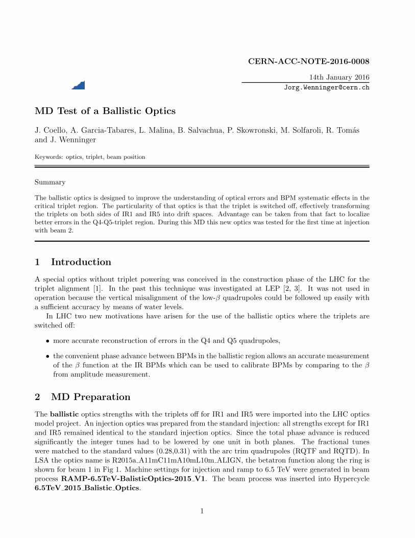
The ballistic optics strengths with the triplets off for IR1 and IR5 were imported into the LHC opticsmodel project. An injection optics was prepared from the standard injection: all strengths except for IR1and IR5 remained identical to the standard injection optics. Since the total phase advance is reducedsignificantly the integer tunes had to be lowered by one unit in both planes. The fractional tuneswere matched to the standard values (0.28,0.31) with the arc trim quadrupoles (RQTF and RQTD). InLSA the optics name is R2015a A11mC11mA10mL10m ALIGN, the betatron function along the ring isshown for beam 1 in Fig 1. Machine settings for injection and ramp to 6.5 TeV were generated in beamprocess RAMP-6.5TeV-BalisticOptics-2015 V1. The beam process was inserted into Hypercycle6.5TeV 2015 Balistic Optics.
1
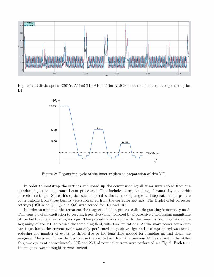
Figure 1: Balistic optics R2015a A11mC11mA10mL10m ALIGN betatron functions along the ring forB1.
Figure 2: Degaussing cycle of the inner triplets as preparation of this MD.
In order to bootstrap the settings and speed up the commissioning all trims were copied from thestandard injection and ramp beam processes. This includes tune, coupling, chromaticity and orbitcorrector settings. Since this optics was operated without crossing angle and separation bumps, thecontributions from those bumps were subtracted from the corrector settings. The triplet orbit correctorsettings (RCBX at Q1, Q2 and Q3) were zeroed for IR1 and IR5.
In order to minimize the remanent the magnetic field, a process called de-gaussing is normally used.This consists of an excitation to very high positive value, followed by progressively decreasing magnitudeof the field, while alternating its sign. This procedure was applied to the Inner Triplet magnets at thebeginning of the MD to reduce the remaining field, with two limitations. As the main power convertersare 1-quadrant, the current cycle was only performed on positive sign and a compromised was foundreducing the number of cycles to three, due to the long time needed for ramping up and down themagnets. Moreover, it was decided to use the ramp-down from the previous MD as a first cycle. Afterthis, two cycles at approximately 50% and 25% of nominal current were performed see Fig. 2. Each timethe magnets were brought to zero current.
2
3 Injection
The MD took place on Saturday November 7th 2015. Due to a WIC problem affecting the TI 2 injectionline, only beam 2 was available during this MD. The fill number was 4596.
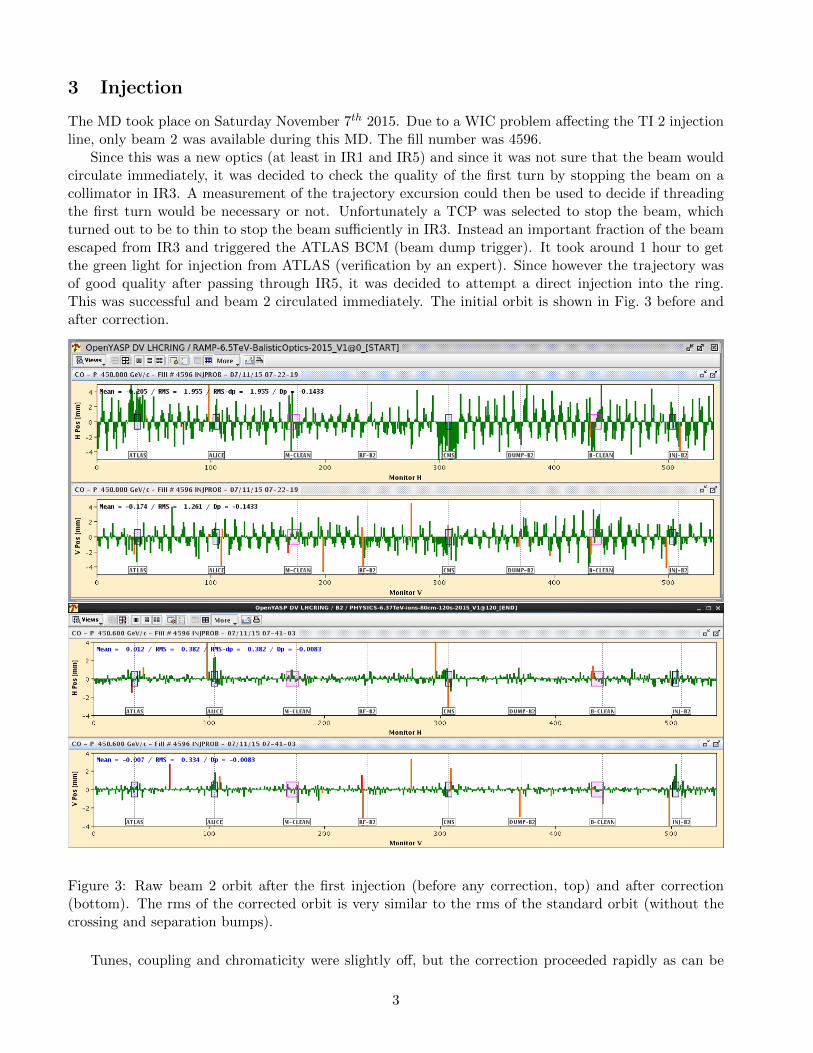
Since this was a new optics (at least in IR1 and IR5) and since it was not sure that the beam wouldcirculate immediately, it was decided to check the quality of the first turn by stopping the beam on acollimator in IR3. A measurement of the trajectory excursion could then be used to decide if threadingthe first turn would be necessary or not. Unfortunately a TCP was selected to stop the beam, whichturned out to be to thin to stop the beam sufficiently in IR3. Instead an important fraction of the beamescaped from IR3 and triggered the ATLAS BCM (beam dump trigger). It took around 1 hour to getthe green light for injection from ATLAS (verification by an expert). Since however the trajectory wasof good quality after passing through IR5, it was decided to attempt a direct injection into the ring.This was successful and beam 2 circulated immediately. The initial orbit is shown in Fig. 3 before andafter correction.
Figure 3: Raw beam 2 orbit after the first injection (before any correction, top) and after correction(bottom). The rms of the corrected orbit is very similar to the rms of the standard orbit (without thecrossing and separation bumps).
Tunes, coupling and chromaticity were slightly off, but the correction proceeded rapidly as can be
3
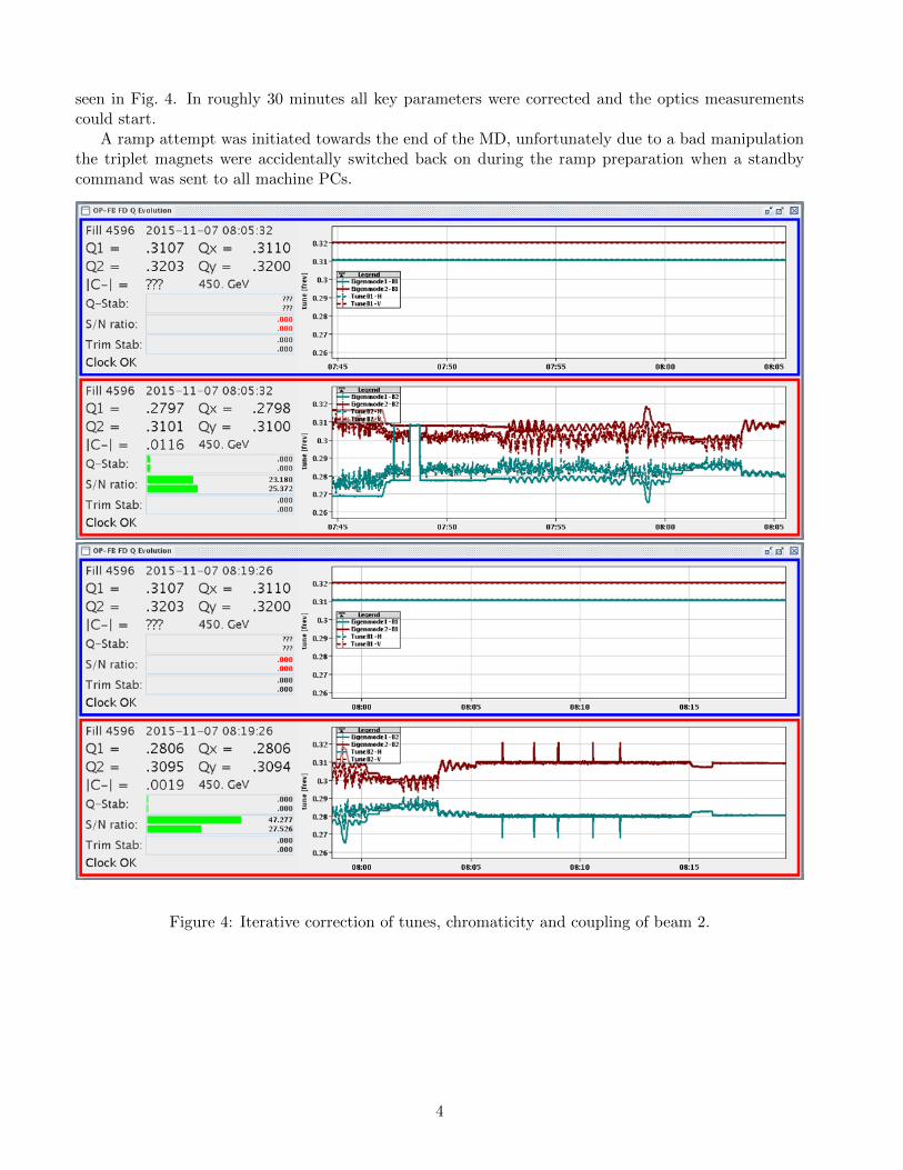
seen in Fig. 4. In roughly 30 minutes all key parameters were corrected and the optics measurementscould start.
A ramp attempt was initiated towards the end of the MD, unfortunately due to a bad manipulationthe triplet magnets were accidentally switched back on during the ramp preparation when a standbycommand was sent to all machine PCs.
Figure 4: Iterative correction of tunes, chromaticity and coupling of beam 2.
4
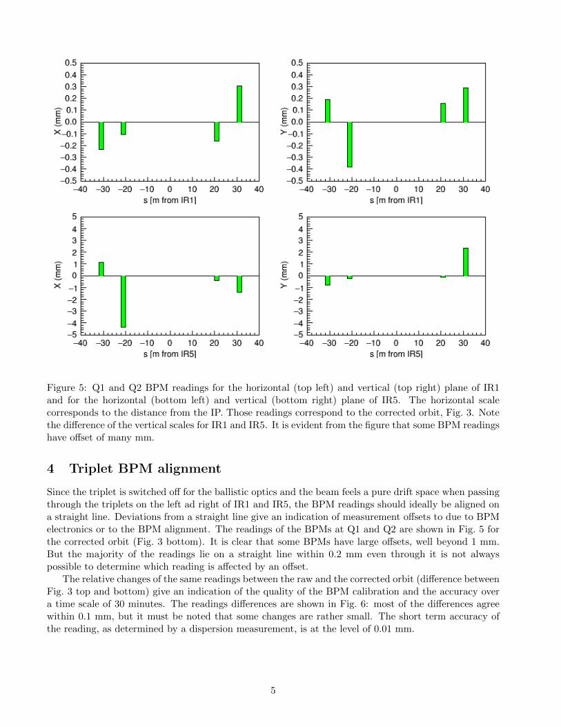
Figure 5: Q1 and Q2 BPM readings for the horizontal (top left) and vertical (top right) plane of IR1and for the horizontal (bottom left) and vertical (bottom right) plane of IR5. The horizontal scalecorresponds to the distance from the IP. Those readings correspond to the corrected orbit, Fig. 3. Notethe difference of the vertical scales for IR1 and IR5. It is evident from the figure that some BPM readingshave offset of many mm.
4 Triplet BPM alignment
Since the triplet is switched off for the ballistic optics and the beam feels a pure drift space when passingthrough the triplets on the left ad right of IR1 and IR5, the BPM readings should ideally be aligned ona straight line. Deviations from a straight line give an indication of measurement offsets to due to BPMelectronics or to the BPM alignment. The readings of the BPMs at Q1 and Q2 are shown in Fig. 5 forthe corrected orbit (Fig. 3 bottom). It is clear that some BPMs have large offsets, well beyond 1 mm.But the majority of the readings lie on a straight line within 0.2 mm even through it is not alwayspossible to determine which reading is affected by an offset.
The relative changes of the same readings between the raw and the corrected orbit (difference betweenFig. 3 top and bottom) give an indication of the quality of the BPM calibration and the accuracy overa time scale of 30 minutes. The readings differences are shown in Fig. 6: most of the differences agreewithin 0.1 mm, but it must be noted that some changes are rather small. The short term accuracy ofthe reading, as determined by a dispersion measurement, is at the level of 0.01 mm.
5
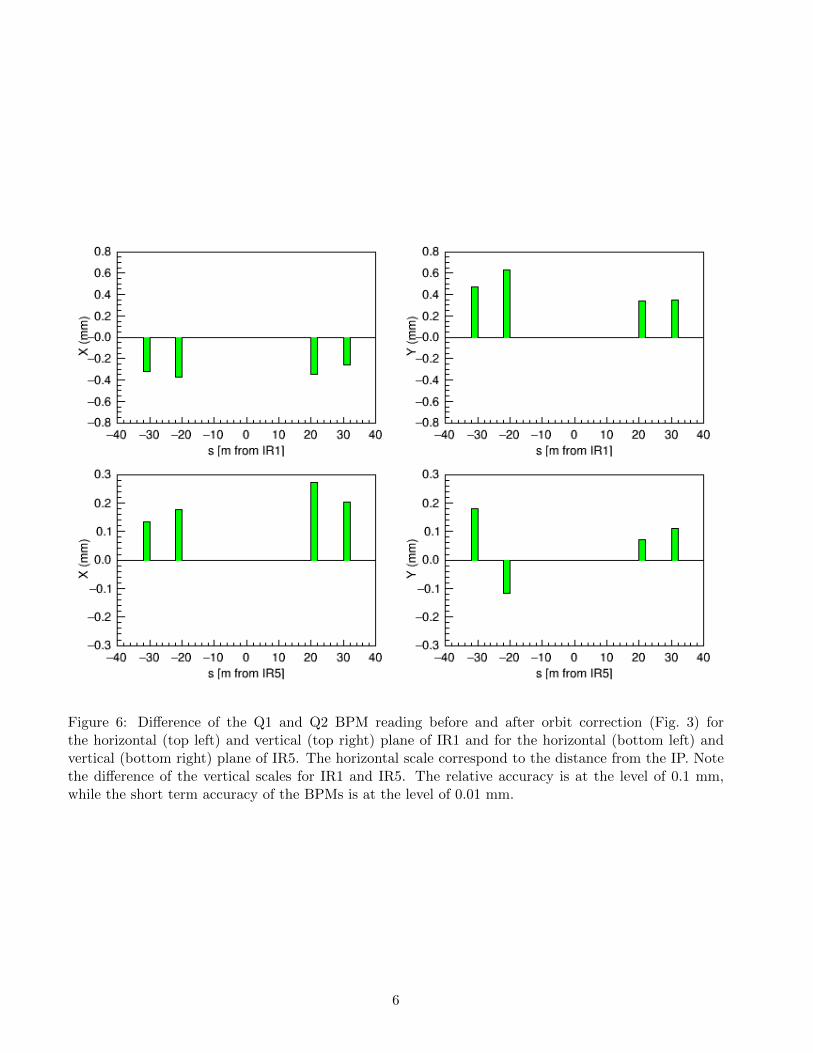
Figure 6: Difference of the Q1 and Q2 BPM reading before and after orbit correction (Fig. 3) forthe horizontal (top left) and vertical (top right) plane of IR1 and for the horizontal (bottom left) andvertical (bottom right) plane of IR5. The horizontal scale correspond to the distance from the IP. Notethe difference of the vertical scales for IR1 and IR5. The relative accuracy is at the level of 0.1 mm,while the short term accuracy of the BPMs is at the level of 0.01 mm.
6
0.4
0.2
0.0
0.2
0.4
∆βx/β
x
LHCB2 injection
0 5000 10000 15000 20000 25000Longitudinal location (m)
0.4
0.2
0.0
0.2
0.4
∆βy/β
yIR7IR8 IR1 IR2 IR3 IR4 IR5 IR6
Ballistic Injection 10-04-15 Virgin LHC
Figure 7: Beam 2 horizontal and vertical β-beating for the virgin nominal and ballistic optics at injectionenergy.
5 Optics measurements
5.1 β-beating in the ballistic optics
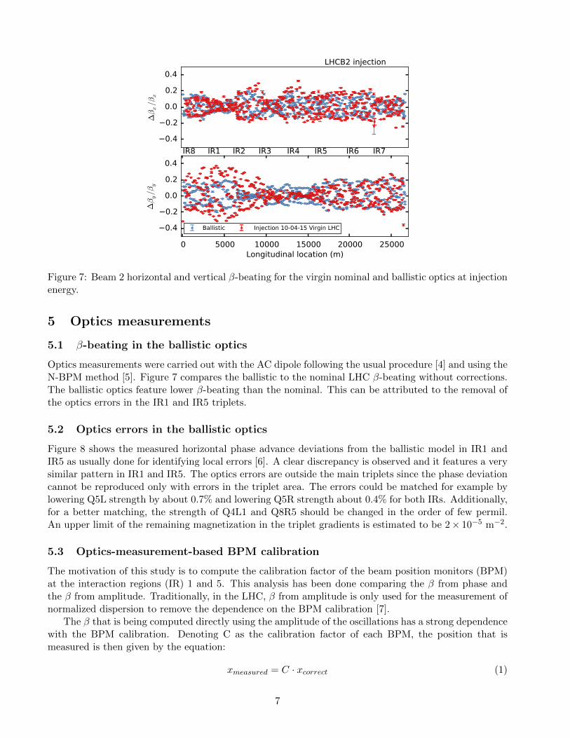
Optics measurements were carried out with the AC dipole following the usual procedure [4] and using theN-BPM method [5]. Figure 7 compares the ballistic to the nominal LHC β-beating without corrections.The ballistic optics feature lower β-beating than the nominal. This can be attributed to the removal ofthe optics errors in the IR1 and IR5 triplets.
5.2 Optics errors in the ballistic optics
Figure 8 shows the measured horizontal phase advance deviations from the ballistic model in IR1 andIR5 as usually done for identifying local errors [6]. A clear discrepancy is observed and it features a verysimilar pattern in IR1 and IR5. The optics errors are outside the main triplets since the phase deviationcannot be reproduced only with errors in the triplet area. The errors could be matched for example bylowering Q5L strength by about 0.7% and lowering Q5R strength about 0.4% for both IRs. Additionally,for a better matching, the strength of Q4L1 and Q8R5 should be changed in the order of few permil.An upper limit of the remaining magnetization in the triplet gradients is estimated to be 2× 10⁻⁵ m−2.
5.3 Optics-measurement-based BPM calibration
The motivation of this study is to compute the calibration factor of the beam position monitors (BPM)at the interaction regions (IR) 1 and 5. This analysis has been done comparing the β from phase andthe β from amplitude. Traditionally, in the LHC, β from amplitude is only used for the measurement ofnormalized dispersion to remove the dependence on the BPM calibration [7].
The β that is being computed directly using the amplitude of the oscillations has a strong dependencewith the BPM calibration. Denoting C as the calibration factor of each BPM, the position that ismeasured is then given by the equation:
xmeasured = C · xcorrect (1)
7
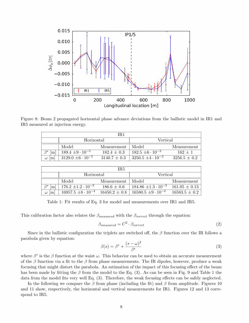
Figure 8: Beam 2 propagated horizontal phase advance deviations from the ballistic model in IR1 andIR5 measured at injection energy.
IR1Horizontal Vertical
Model Measurement Model Measurementβ∗ [m] 189.4 ±9 · 10−5 182.4 ± 0.3 182.5 ±6 · 10−3 162 ± 1ω [m] 3129.0 ±6 · 10−5 3140.7 ± 0.3 3250.5 ±4 · 10−3 3256.5 ± 0.2
IR5Horizontal Vertical
Model Measurement Model Measurementβ∗ [m] 176.2 ±1.2 · 10−3 186.6 ± 0.6 184.86 ±1.3 · 10−3 161.05 ± 0.13ω [m] 16957.5 ±8 · 10−4 16450.2 ± 0.8 16580.5 ±9 · 10−4 16583.5 ± 0.2
Table 1: Fit results of Eq. 3 for model and measurements over IR1 and IR5.
This calibration factor also relates the βmeasured with the βcorrect through the equation:
βmeasured = C2 · βcorrect (2)
Since in the ballistic configuration the triplets are switched off, the β function over the IR follows aparabola given by equation:
β(s) = β∗ +(s− ω)2
β∗(3)
where β∗ is the β function at the waist ω. This behavior can be used to obtain an accurate measurementof the β function via a fit to the β from phase measurements. The IR dipoles, however, produce a weakfocusing that might distort the parabola. An estimation of the impact of this focusing effect of the beamhas been made by fitting the β from the model to the Eq. (3). As can be seen in Fig. 9 and Table 1 thedata from the model fits very well Eq. (3). Therefore, the weak focusing effects can be safely neglected.
In the following we compare the β from phase (including the fit) and β from amplitude. Figures 10and 11 show, respectively, the horizontal and vertical measurements for IR1. Figures 12 and 13 corre-spond to IR5.
8
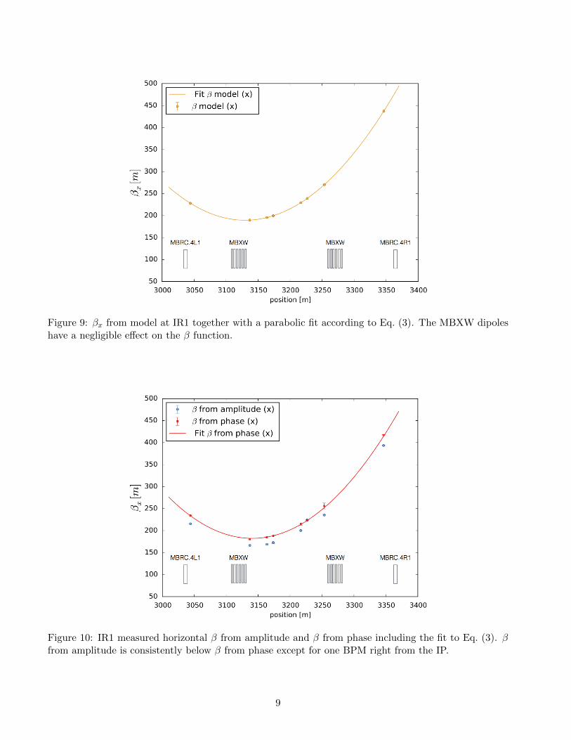
Figure 9: βx from model at IR1 together with a parabolic fit according to Eq. (3). The MBXW dipoleshave a negligible effect on the β function.
Figure 10: IR1 measured horizontal β from amplitude and β from phase including the fit to Eq. (3). βfrom amplitude is consistently below β from phase except for one BPM right from the IP.
9
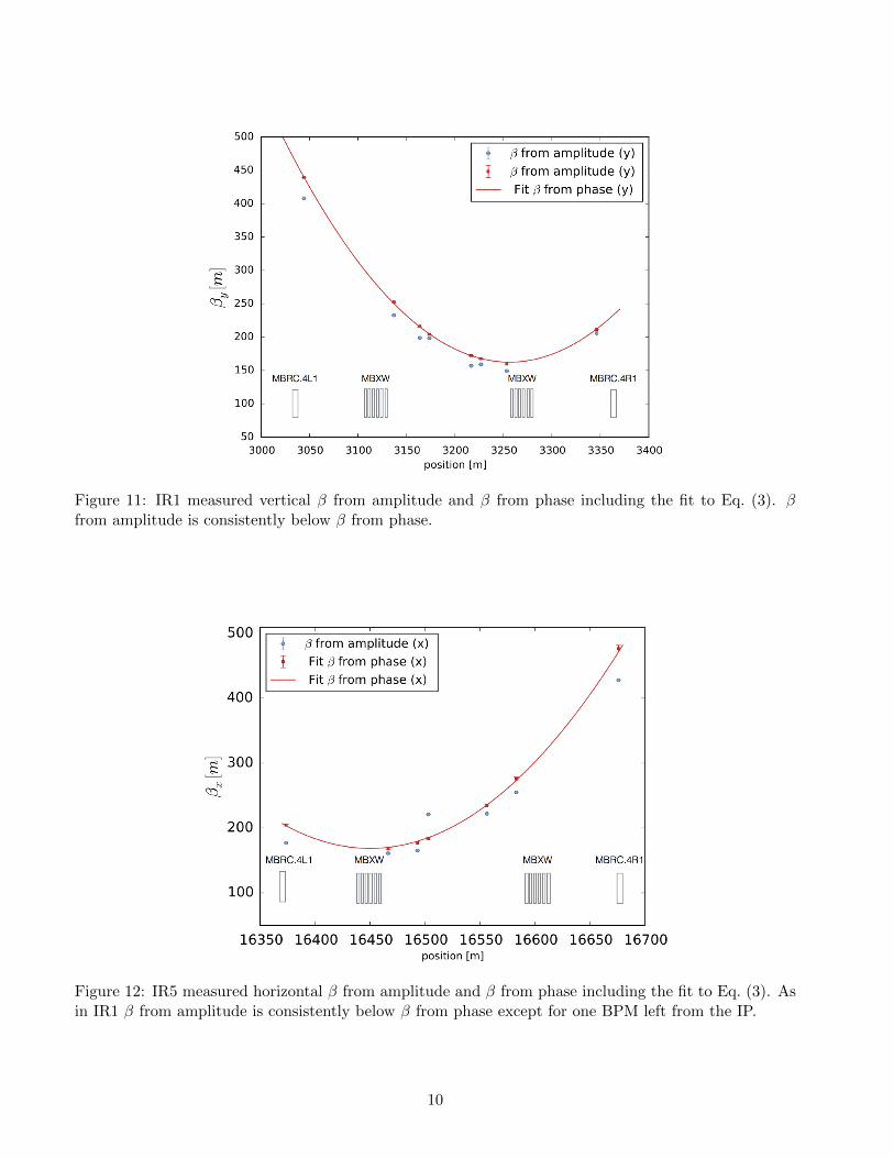
Figure 11: IR1 measured vertical β from amplitude and β from phase including the fit to Eq. (3). βfrom amplitude is consistently below β from phase.
Figure 12: IR5 measured horizontal β from amplitude and β from phase including the fit to Eq. (3). Asin IR1 β from amplitude is consistently below β from phase except for one BPM left from the IP.
10
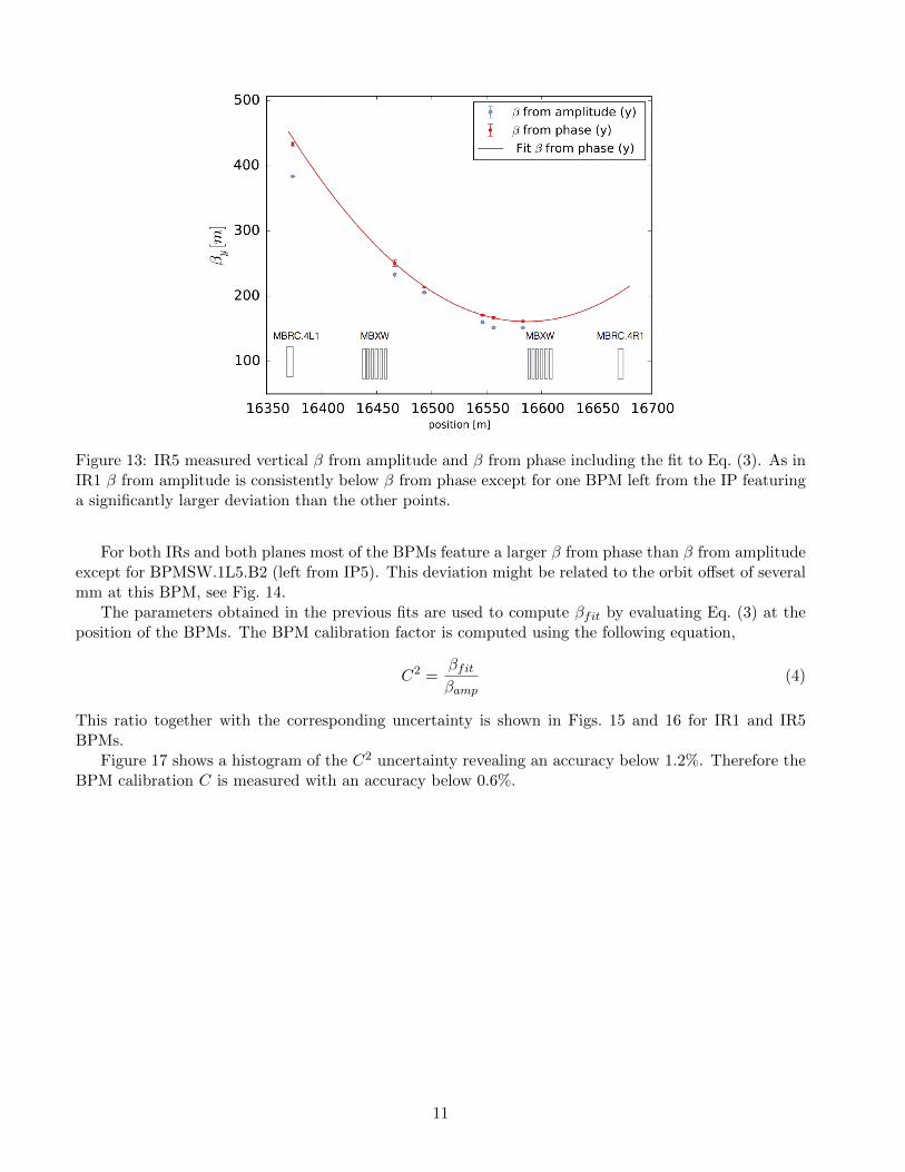
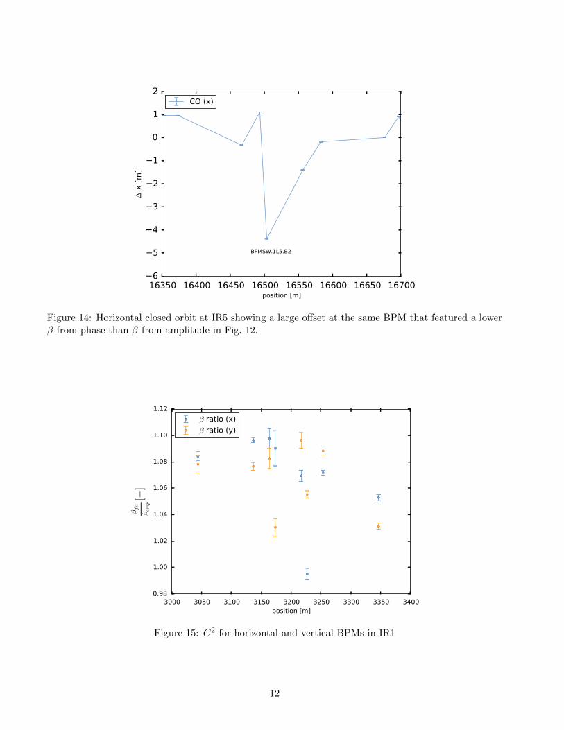
Figure 13: IR5 measured vertical β from amplitude and β from phase including the fit to Eq. (3). As inIR1 β from amplitude is consistently below β from phase except for one BPM left from the IP featuringa significantly larger deviation than the other points.
For both IRs and both planes most of the BPMs feature a larger β from phase than β from amplitudeexcept for BPMSW.1L5.B2 (left from IP5). This deviation might be related to the orbit offset of severalmm at this BPM, see Fig. 14.
The parameters obtained in the previous fits are used to compute βfit by evaluating Eq. (3) at theposition of the BPMs. The BPM calibration factor is computed using the following equation,
C2 =βfitβamp
(4)
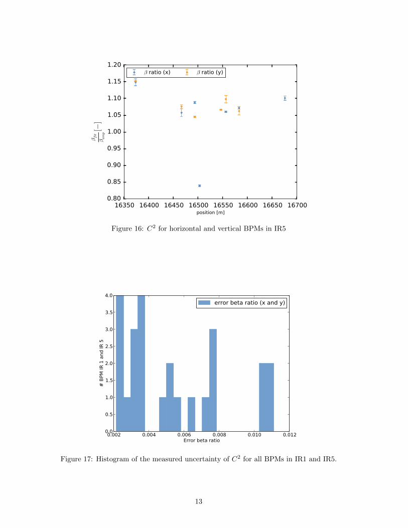
This ratio together with the corresponding uncertainty is shown in Figs. 15 and 16 for IR1 and IR5BPMs.
Figure 17 shows a histogram of the C2 uncertainty revealing an accuracy below 1.2%. Therefore theBPM calibration C is measured with an accuracy below 0.6%.
11
16350 16400 16450 16500 16550 16600 16650 16700position [m]
6
5
4
3
2
1
0
1
2
∆ x
[m
]
BPMSW.1L5.B2
CO (x)
Figure 14: Horizontal closed orbit at IR5 showing a large offset at the same BPM that featured a lowerβ from phase than β from amplitude in Fig. 12.
3000 3050 3100 3150 3200 3250 3300 3350 3400position [m]
0.98
1.00
1.02
1.04
1.06
1.08
1.10
1.12
βfit
βamp[−
]
β ratio (x)
β ratio (y)
Figure 15: C2 for horizontal and vertical BPMs in IR1
12
16350 16400 16450 16500 16550 16600 16650 16700position [m]
0.80
0.85
0.90
0.95
1.00
1.05
1.10
1.15
1.20
βfit
βamp[−
]
β ratio (x) β ratio (y)
Figure 16: C2 for horizontal and vertical BPMs in IR5
0.002 0.004 0.006 0.008 0.010 0.012Error beta ratio
0.0
0.5
1.0
1.5
2.0
2.5
3.0
3.5
4.0
# B
PM IR
1 a
nd IR
5
error beta ratio (x and y)
Figure 17: Histogram of the measured uncertainty of C2 for all BPMs in IR1 and IR5.
13

6 Summary and outlook
The ballistic optics has allowed to estimate Q5 errors and BPM calibrations with unprecedented accuracy.In particular Q5L and Q5R strengths seem to be lower by about 0.7% and 0.4%, respectively. An upperlimit of the remaining magnetization in the triplet gradients is estimated to be about 2× 10⁻⁵ m−2. Attop energy this should be a factor 14 lower.
In the future it will be required to measure both beams at injection and at top energy. It will befundamental to study the calibration dependence with beam offsets in the BPMs since a strong deviationon C has been observed in the horizontal BPMSW.1L5.B2, the only BPM with more than 4 mm beamoffset.
7 Acknowledgements
Great thanks to E. Todesco and P. Hagen for discussions concerning the uni-polar demagnetizationprocedure. Many thanks also to T. Risselada, M. Giovannozzi and R. de Maria for maintaining theMADX ballistic optics conceived by A. Verdier [1].
References
[1] A. Verdier, “Alignment optics for LHC”, LHC Project Note 325, October 6, 2003.
[2] F. Bordry, P. Collier and A. Verdier, “Check of the BPM alignment with the LEP beam”, SL-MDNote 99 (September 6, 1993).
[3] A. Verdier, “Estimation of the vertical misalignment of the low-β quadrupoles in IP2 and IP6”,SL-MD Note 188 (October 24, 1995).
[4] R. Tomas, O. Bruning, M. Giovannozzi, P. Hagen, M. Lamont, F. Schmidt, G. Vanbavinckhove,M. Aiba, R. Calaga, and R. Miyamoto, “LHC optics model, measurements and corrections”, Phys.Rev. ST Accel. Beams 13, 121004 (2010).
[5] A. Langner and R. Tomas, “Optics measurement algorithms and error analysis for the proton energyfrontier”, Phys. Rev. ST Accel. Beams 18, 031002 (2015).
[6] R. Tomas, T. Bach, R. Calaga, A. Langner, Y.I. Levinsen, E.H. Maclean, T.H.B. Persson,P.K. Skowronski, M. Strzelczyk, G. Vanbavinckhove and R. Miyamoto “Record low beta beating inthe LHC”, Phys. Rev. ST Accel. Beams 15, 091001 (2012).
[7] R. Calaga, R. Tomas and F. Zimmermann, “BPM calibration independent LHC optics correction”,Proceedings of PAC07, Albuquerque, New Mexico, USA.
14