Embed Size (px)
Citation preview
User Manual /Manual de Uso
MD 82 AX
Rev 16.02.01
1 User Manual / Manual de uso MD 82 AX
EN
This symbol, wherever used,alerts you to the presence of un-isulated and dangerousvoltages within the product enclosure. These are voltages that may be sufficient toconstitute the risk of electric shock.
This symbol, wherever used, alerts you toimportant operating and maintenanceinstructions. Please read.
Protective Ground Terminal
AC mains (Alternating Current)
Hazardous Live Terminal
ON: Denotes the product is turned on.
OFF: Denotes the product is turned off.
WARNING
Describes precautions that should be observed toprevent the possibility of death or injury to the user.
CAUTION
Describes precautions that should be observed toprevent damage to the product.
WARNING
Power Supply
Ensure that the mains source voltage (AC outlet)matches the voltage rating of the product. Failureto do so could result in damage to the product andpossibly the user.
Unplug the product before electrical storms occurand when unused for long periods of time to reducethe risk of electric shock or fire.
External Connection
Always use proper ready-made insulated mainscabling (power cord). Failure to do so could resultin shock or fire. If in doubt, seek advice from aregistered electrician.
Do not Remove Any Cover
Within the product are areas where high voltagesmay bepresent. To reduce the risk of electric shockdo not remove any covers unless the AC mains power cord is removed.
Covers should be removed by qualified servicepersonnel only.No user serviciable parts inside.
Fuse
To prevent fire an damage to the product, use onlythe recommended fuse type as indicated in thismanual. Do not short-circuit the fuse holder.Before replacing fuse, make sure that the productis OFF and disconnected from the AC outlet.
Protective Ground
Before turning the product ON, make sure that it isconnected to Ground. This is to prevent the risk ofelectric shock.
Never cut internal or external Ground wires. Likewise,never remove Ground wiring from the ProtectiveGround Terminal.
Operating Conditions
Always install in accordance with the manufacturer´s instructions.
To avoid the risk of electrtic shock and damage, donot subject the product to any liquid/rain or moisture.Do not use this product when in close proximity towater.Do not install this product near any direct heat source.Do not block areas of ventilation.
SAFETY RELATED SYMBOLS
GRAPHICAL SYMBOLS EXPLANATION
TO REDUCE THE RISK OF FIRE ORELECTRIC SHOCK, DO NOT EXPOSETO RAIN OR HUMIDITY.DO NOT REMOVE COVER. THIS PRODUCT ISNOT INTENDED FOR USE OTHER THANSTATED.
WARNING:
MD 82 AX is a mixer for microphones which integrates a large series of attractive features that allow to optimize theinstallation and to outfit with multiple audio signal control and management possibilities. This mixer incorporates 8 balanced inputs. It provides individual input level control and master level.
The encoder in the frontal side allows to navigate through a configuration menu with the different parameters on each channel. Among the functions to be performed, we can set three tone control, low-pass and high-pass filters (with frequency adjustment) and 4 anti-feedback levels.
All this information is showed in the LCD display. All inputs have switch to enable the connection of +48V phantom power supply microphones. The two features that represent an interesting development are the Auto-mixer functionality and the RS485 interface for external commands
1.0 Introduction
1.1 Features:
8 Microphone inputs(with 48V phantom power)
Each signal with high cut, low cut
Each signal with AGC
Each signal FBC feedback suppression
Each signal has Three-band EQ
Two mixed output
RS485 remote control(PC or centre control)
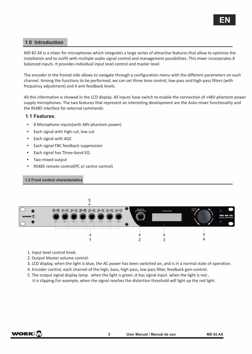
1.2 Front control characteristics
1. Input level control knob.2. Output Master volume control.3. LCD display, when the light is blue, the AC power has been switched on, and is in a normal state of operation.
4. Encoder control, each channel of the high, bass, high pass, low pass filter, feedback gain control.5. The output signal display lamp. when the light is green ,it has signal input. when the light is red , it is clipping.For example, when the signal reaches the distortion threshold will light up the red light.
2 3 4
5
11
2 User Manual / Manual de uso MD 82 AX
EN
ON OFF ON OFF ON OFF ON OFF
CH5 CH4 CH3 CH2 CH1OUT1 OUT2 MIXING CH8 CH7 CH6
GG G G G G G G G G G
48V 48V 48V 48V
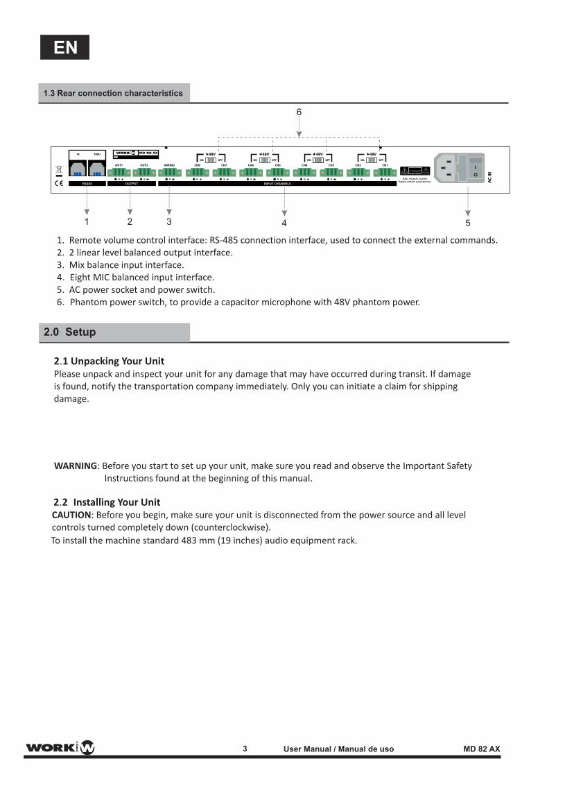
1.3 Rear connection characteristics
1. Remote volume control interface: RS-485 connection interface, used to connect the external commands.2. 2 linear level balanced output interface.3. Mix balance input interface.4. Eight MIC balanced input interface.5. AC power socket and power switch.6. Phantom power switch, to provide a capacitor microphone with 48V phantom power.
2.0 Setup
2.1 Unpacking Your UnitPlease unpack and inspect your unit for any damage that may have occurred during transit. If damage is found, notify the transportation company immediately. Only you can initiate a claim for shipping damage.
WARNING: Before you start to set up your unit, make sure you read and observe the Important Safety Instructions found at the beginning of this manual.
2.2 Installing Your Unit CAUTION: Before you begin, make sure your unit is disconnected from the power source and all level controls turned completely down (counterclockwise).
To install the machine standard 483 mm (19 inches) audio equipment rack.
1 2 3 4 5
6
3 User Manual / Manual de uso MD 82 AX
EN
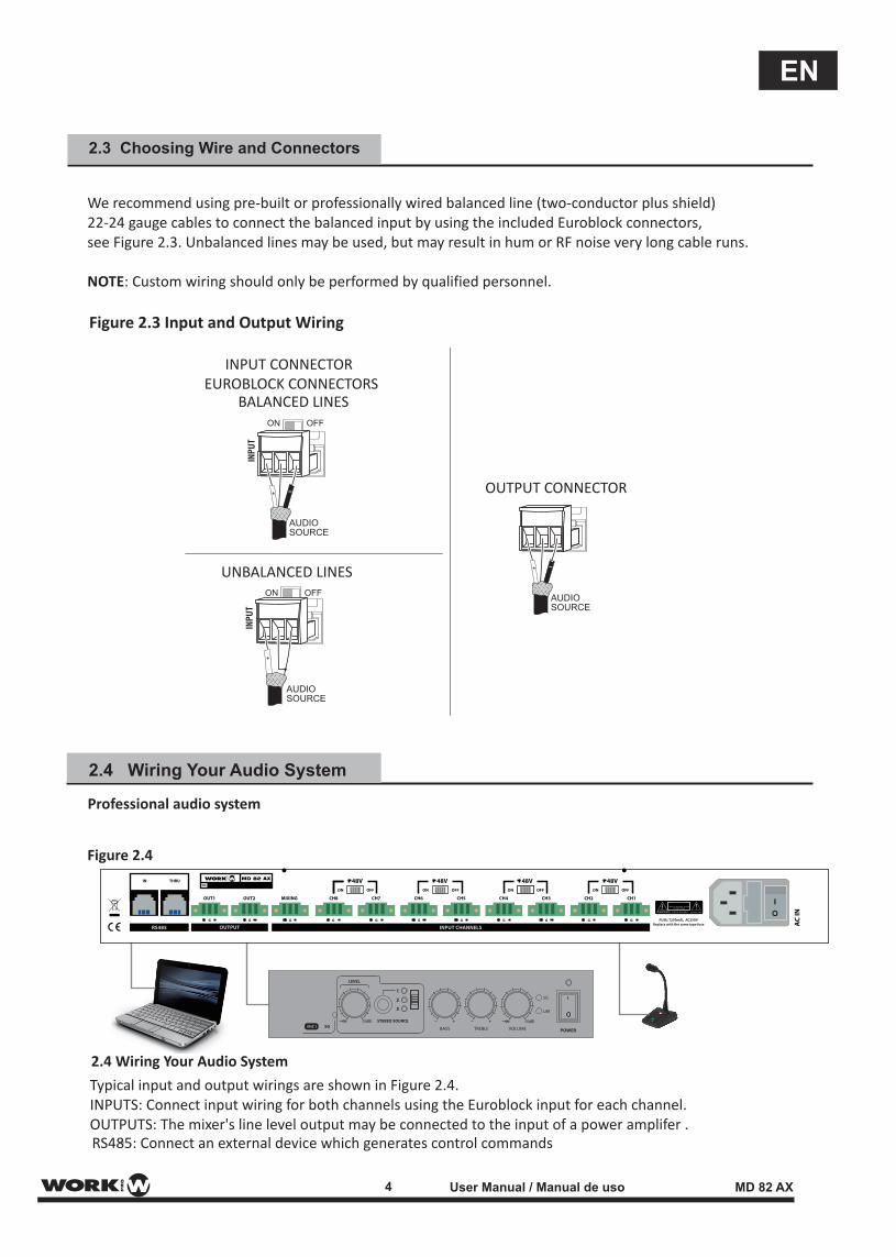
RS485: Connect an external device which generates control commands
2.3 Choosing Wire and Connectors
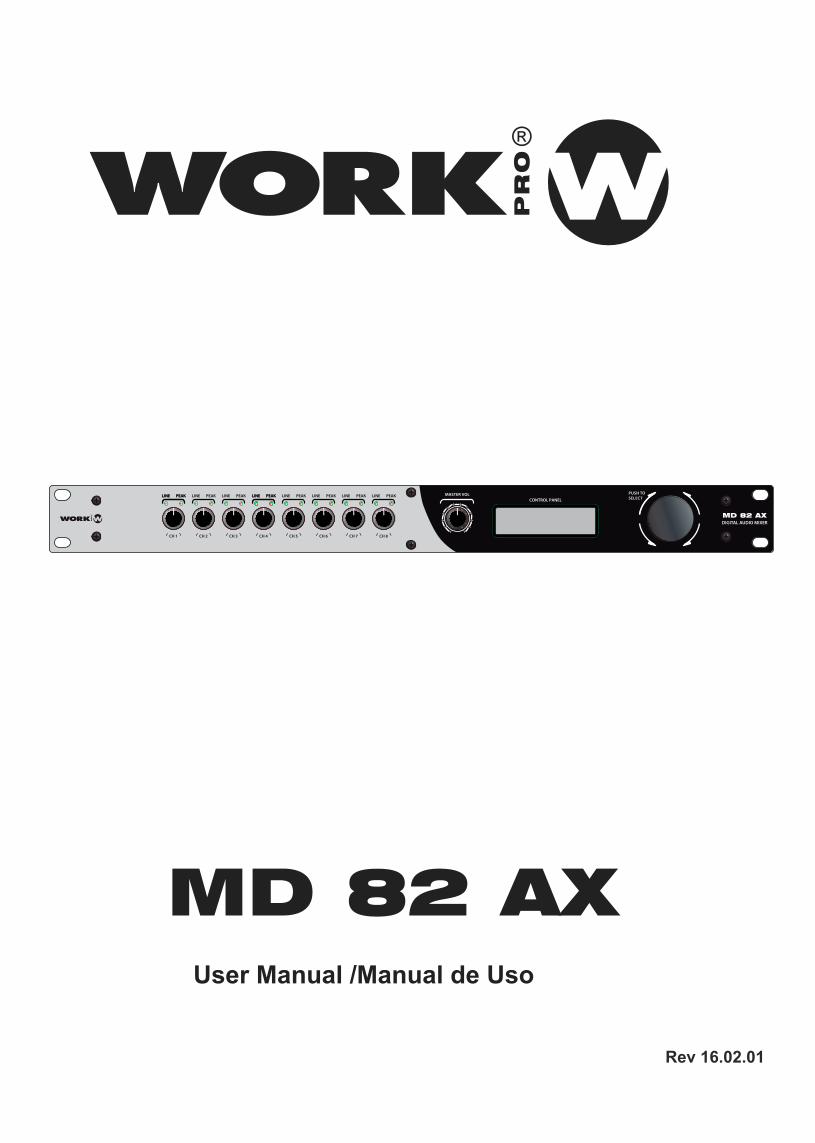
We recommend using pre-built or professionally wired balanced line (two-conductor plus shield) 22-24 gauge cables to connect the balanced input by using the included Euroblock connectors, see Figure 2.3. Unbalanced lines may be used, but may result in hum or RF noise very long cable runs.
NOTE: Custom wiring should only be performed by qualified personnel.
Figure 2.3 Input and Output Wiring
2.4 Wiring Your Audio System
Professional audio system
2.4 Wiring Your Audio System
Typical input and output wirings are shown in Figure 2.4. INPUTS: Connect input wiring for both channels using the Euroblock input for each channel. OUTPUTS: The mixer's line level output may be connected to the input of a power amplifer .
Figure 2.4
AUDIOSOURCE
ON OFF
AUDIOSOURCE
ON OFFAUDIOSOURCE
INPUT CONNECTOREUROBLOCK CONNECTORS
UNBALANCED LINES
OUTPUT CONNECTOR
BALANCED LINES
ON OFF ON OFF ON OFF ON OFF
CH5 CH4 CH3 CH2 CH1OUT1 OUT2 MIXING CH8 CH7 CH6
GG G G G G G G G G G
48V 48V 48V 48V
4 User Manual / Manual de uso MD 82 AX
EN
This functionality allows to set a value (TARGET) marked as maximum level of the channel, and another parameter (GAIN), which marks the quantity of amplification that the channel needs to reach the TARGET value. This functionality provides several configurations saccording to the installation requirements. One option will be to set the same TARGET threshold in all channels in order the all microphones have the same level. Another option will be to set several TARGET values on each channel in order that these channels will have preponderance over the rest.
This gain correction is made in real time, allowing an autonomous control in the installation without being worried about the controls once set the desired configuration.
2.5 Connecting to AC Mains
2.6 Startup Procedure
3.0 Automixer (Explanation)
Connect your mixer to the AC mains power source (power outlet) with the supplied AC power cord.First, connect the IEC end of the cord set to the IEC connector on the mixer; then, plug the other end of the cord set to the AC mains.
WARNING: The third prong of this connector (ground) is an important safety feature. Do not attempt to disable this ground connection by using an adapter or other methods.
Use the following procedure when first turning on your system: 1. Turn down the level of your audio source. 2. Turn down the level controls of the amplifier. 3. Power up the mixer. The display is lighting. 4. Power up the amplifier that is connected to the mixer output. 5. Turn up the level of your audio source to an optimum level. 6. Turn up the level of your mixer to an optimum level. 7. Turn up the Level controls on the amplifier until the desired loudness or power level is achieved. If you ever need to make any wiring or installation changes, don't forget to disconnect the power cord.
Note: To avoid pop noises when powering down your system, it is recommended that the amplifier used to drive the loudspeakers be turned off before the other system components.
5 User Manual / Manual de uso MD 82 AX
EN
3.3 RS485 control
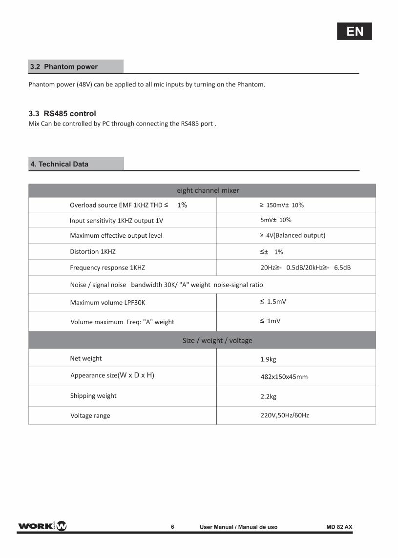
Phantom power (48V) can be applied to all mic inputs by turning on the Phantom.
Mix Can be controlled by PC through connecting the RS485 port .
3.2 Phantom power
4. Technical Data
eight channel mixer
Size / weight / voltage
Net weight 1.9kg
482x150x45mm
2.2kg
220V,50Hz/60Hz
Appearance size(W x D x H)
Shipping weight
Voltage range
Overload source EMF 1KHZ THD ≤ 1%
Input sensitivity 1KHZ output 1V
Maximum effective output level
Distortion 1KHZ
Frequency response 1KHZ
Noise / signal noise bandwidth 30K/ "A" weight noise-signal ratio
Maximum volume LPF30K
Volume maximum Freq: "A" weight
≥ 150mV± 10%
≥ 4V(Balanced output)
20Hz≥- 0.5dB/20kHz≥- 6.5dB
≤± 1%
≤ 1.5mV
≤ 1mV
5mV± 10%
6 User Manual / Manual de uso MD 82 AX
EN
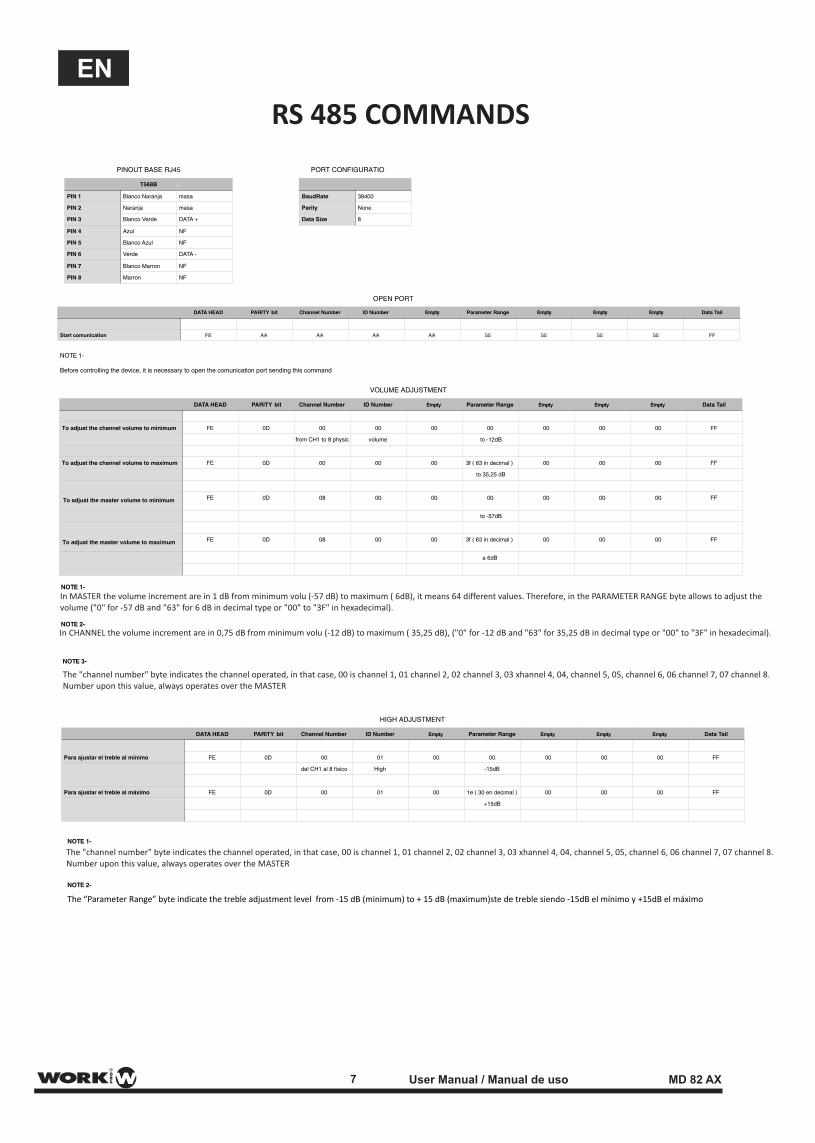
VOLUME ADJUSTMENT
DATA HEAD PARITY bit Channel Number ID Number Empty Parameter Range Empty Empty Empty Data Tail
To adjust the channel volume to minimum
To adjust the master volume to minimum
To adjust the master volume to maximum
FE 0D 00 00 00 00 00 00 00 FF
from CH1 to 8 physic volume to -12dB
To adjust the channel volume to maximum FE 0D 00 00 00 3f ( 63 in decimal ) 00 00 00 FF
to 35,25 dB
FE 0D 08 00 00 00 00 00 00 FF
to -57dB
FE 0D 08 00 00 3f ( 63 in decimal ) 00 00 00 FF
a 6dB
PINOUT BASE RJ45
T568B
PIN 1 Blanco Naranja masa
PIN 2 Naranja masa
PIN 3 Blanco Verde DATA +
PIN 4 Azul NF
PIN 5 Blanco Azul NF
PIN 6 Verde DATA -
PIN 7 Blanco Marron NF
PIN 8 Marron NF
NOTE 1-
NOTE 2-
NOTE 3-
OPEN PORT
DATA HEAD PARITY bit Channel Number ID Number Empty Parameter Range Empty Empty Empty Data Tail
Start comunication FE AA AA AA AA 55 55 55 55 FF
PORT CONFIGURATIO
BaudRate 38400
Parity None
Data Size 8
HIGH ADJUSTMENT
DATA HEAD PARITY bit Channel Number ID Number Empty Parameter Range Empty Empty Empty Data Tail
Para ajustar el treble al mínimo FE 0D 00 01 00 00 00 00 00 FF
del CH1 al 8 físico High -15dB
Para ajustar el treble al máximo FE 0D 00 01 00 1e ( 30 en decimal ) 00 00 00 FF
+15dB
NOTE 1-
Before controlling the device, it is necessary to open the comunication port sending this command
NOTE 1-
NOTE 2-
The “Parameter Range” byte indicate the treble adjustment level from -15 dB (minimum) to + 15 dB (maximum)ste de treble siendo -15dB el mínimo y +15dB el máximo
7 User Manual / Manual de uso MD 82 AX
EN
RS 485 COMMANDS
In MASTER the volume increment are in 1 dB from minimum volu (-57 dB) to maximum ( 6dB), it means 64 different values. Therefore, in the PARAMETER RANGE byte allows to adjust the volume ("0" for -57 dB and "63" for 6 dB in decimal type or "00" to "3F" in hexadecimal).
In CHANNEL the volume increment are in 0,75 dB from minimum volu (-12 dB) to maximum ( 35,25 dB), ("0" for -12 dB and "63" for 35,25 dB in decimal type or "00" to "3F" in hexadecimal).
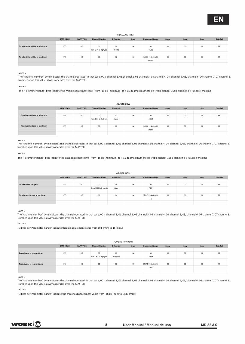
The "channel number" byte indicates the channel operated, in that case, 00 is channel 1, 01 channel 2, 02 channel 3, 03 xhannel 4, 04, channel 5, 05, channel 6, 06 channel 7, 07 channel 8. Number upon this value, always operates over the MASTER
The "channel number" byte indicates the channel operated, in that case, 00 is channel 1, 01 channel 2, 02 channel 3, 03 xhannel 4, 04, channel 5, 05, channel 6, 06 channel 7, 07 channel 8. Number upon this value, always operates over the MASTER
DATA HEAD PARITY bit Channel Number ID Number
To adjust the middle to minimum FE 0D 00
from CH1 to 8 physic middle
To adjust the middle to maximum FE 0D 00
DATA HEAD PARITY bit Channel Number ID Number
FE 0D 00
from CH1 to 8 physic
from CH1 to 8 physic
bass
FE 0D 00
DATA HEAD PARITY bit Channel Number ID Number
MID ADJUSTMENT
Empty Parameter Range Empty Empty Empty Data Tail
02 00 00 00 00 00 FF
-15dB
02 00 1e ( 30 in decimal ) 00 00 00 FF
+15dB
AJUSTE LOW
Empty Parameter Range Empty Empty Empty Data Tail
03 00 00 00 00 00 FF
-15dB
03 00 1e ( 30 in decimal ) 00 00 00 FF
+15dB
AJUSTE GAIN
Empty Parameter Range Empty Empty Empty Data Tail
To deactivate the gain FE 0D 00 04 00 00 00 00 00 FF
Gain OFF
To adjusdt the gain to maximum FE 0D 00 04 00 0f ( 15 in decimal ) 00 00 00 FF
15
AJUSTE Thresholds
DATA HEAD PARITY bit Channel Number ID Number Empty Parameter Range Empty Empty Empty Data Tail
Para ajustar el valor mínimo FE 0D 00 05 00 00 00 00 00 FF
from CH1 to 8 physic Threshold -18dB
Para ajustar el valor máximo FE 0D 00 05 00 0f ( 15 in decimal ) 00 00 00 FF
-3dB
NOTA 2-
NOTA 2-
El byte de “Parameter Range” indicate the threshold adjustment value from -18 dB (min) to -3 dB (max.)
El byte de “Parameter Range” indicate thegain adjustment value from OFF (min) to 15(max.)
8 User Manual / Manual de uso MD 82 AX
EN
The "channel number" byte indicates the channel operated, in that case, 00 is channel 1, 01 channel 2, 02 channel 3, 03 xhannel 4, 04, channel 5, 05, channel 6, 06 channel 7, 07 channel 8. Number upon this value, always operates over the MASTER
The "channel number" byte indicates the channel operated, in that case, 00 is channel 1, 01 channel 2, 02 channel 3, 03 xhannel 4, 04, channel 5, 05, channel 6, 06 channel 7, 07 channel 8. Number upon this value, always operates over the MASTER
NOTE 1-
NOTE 1-
NOTE 2-
NOTE 2-
The “Parameter Range” byte indicate the Middle adjustment level from -15 dB (minimum) to + 15 dB (maximum)ste de treble siendo -15dB el mínimo y +15dB el máximo
The “Parameter Range” byte indicate the Bass adjustment level from -15 dB (minimum) to + 15 dB (maximum)ste de treble siendo -15dB el mínimo y +15dB el máximo
To adjust the bass to minimum
To adjust the bass to maximum
NOTE 1-
NOTE 1-
The "channel number" byte indicates the channel operated, in that case, 00 is channel 1, 01 channel 2, 02 channel 3, 03 xhannel 4, 04, channel 5, 05, channel 6, 06 channel 7, 07 channel 8. Number upon this value, always operates over the MASTER
The "channel number" byte indicates the channel operated, in that case, 00 is channel 1, 01 channel 2, 02 channel 3, 03 xhannel 4, 04, channel 5, 05, channel 6, 06 channel 7, 07 channel 8. Number upon this value, always operates over the MASTER
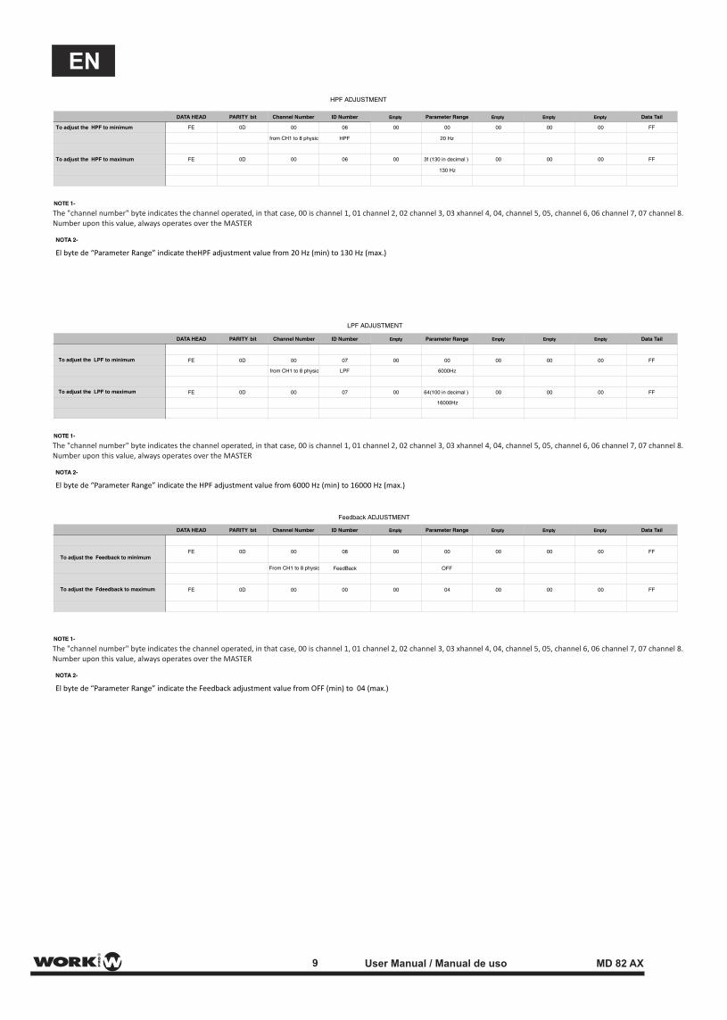
To adjust the HPF to minimum FE 0D 00 06
from CH1 to 8 physic HPF
To adjust the HPF to maximum FE 0D 00 06
DATA HEAD PARITY bit Channel Number ID Number
DATA HEAD PARITY bit Channel Number ID Number
FE 0D 00 07
from CH1 to 8 physic LPF
FE 0D 00 07
00 00 00 00 00 FF
20 Hz
00 3f (130 in decimal ) 00 00 00 FF
130 Hz
Empty Parameter Range Empty Empty Empty Data Tail
LPF ADJUSTMENT
HPF ADJUSTMENT
Empty Parameter Range Empty Empty Empty Data Tail
00 00 00 00 00 FF
6000Hz
00 64(100 in decimal ) 00 00 00 FF
16000Hz
Feedback ADJUSTMENT
DATA HEAD PARITY bit Channel Number ID Number Empty Parameter Range Empty Empty Empty Data Tail
FE 0D 00 08 00 00 00 00 00 FF
From CH1 to 8 physic FeedBack OFF
FE 0D 00 00 00 04 00 00 00 FF
9 User Manual / Manual de uso MD 82 AX
EN
NOTA 2-
NOTA 2-
NOTA 2-
El byte de “Parameter Range” indicate theHPF adjustment value from 20 Hz (min) to 130 Hz (max.)
El byte de “Parameter Range” indicate the HPF adjustment value from 6000 Hz (min) to 16000 Hz (max.)
El byte de “Parameter Range” indicate the Feedback adjustment value from OFF (min) to 04 (max.)
NOTE 1-
NOTE 1-
NOTE 1-
The "channel number" byte indicates the channel operated, in that case, 00 is channel 1, 01 channel 2, 02 channel 3, 03 xhannel 4, 04, channel 5, 05, channel 6, 06 channel 7, 07 channel 8. Number upon this value, always operates over the MASTER
The "channel number" byte indicates the channel operated, in that case, 00 is channel 1, 01 channel 2, 02 channel 3, 03 xhannel 4, 04, channel 5, 05, channel 6, 06 channel 7, 07 channel 8. Number upon this value, always operates over the MASTER
The "channel number" byte indicates the channel operated, in that case, 00 is channel 1, 01 channel 2, 02 channel 3, 03 xhannel 4, 04, channel 5, 05, channel 6, 06 channel 7, 07 channel 8. Number upon this value, always operates over the MASTER
To adjust the LPF to minimum
To adjust the LPF to maximum
To adjust the Feedback to minimum
To adjust the Fdeedback to maximum
Este símbolo, cuando aparece, le alertade la presencia de un voltaje peligroso y no aislado dentro del producto. este voltaje puede ser suficiente para constituir un riesgo de descarga eléctrica.
Este símbolo, cuando se use, le alerta de una instrucción de funcionamiento o seguridad importante. Por favor, léala
Terminal de protección de toma tierra.
Alimentación AC (Corriente Alterna)
Terminal cargado (peligro)
ON: Denota que el producto está encendido.
OFF: Denota que el producto está apagado.
WARNING
Describe precauciones que deben ser observadaspara prevenir la posibilidad de muerte o daños alusuario.
CAUTION
Describe precauciones que deben ser observadaspara prevenir daños en el producto.
WARNING
Alimentación
Asergúrese que la toma de alimentación (Toma AC)es igual a la marcada por el producto. Si no es así el producto podría dañarse e incluso dañar al usuario.
Desconecte el producto antes de una tormentaeléctrica y cuando vaya a dejar de usarlo duranteperiodos largos de tiempo para reducir el riesgo dedescargas eléctricas.
Conexiones Externas
Utilice siempre el cable de alimentación aisladosuministrado. En caso de no hacerlo, puede incurriren un riesgo de descarga eléctrica o fuego. En casode duda, consulte a un electricista especializado.
No retire ninguna cubierta
Dentro del producto hay zonas con tensiones altaspresentes. Para reducir el riesgo de descargaseléctricas no quite las tapas a menos que el cableAC esté retirado.
Las tapas sólo deben ser retiradas por personalcualificado.No hay elementos de control para el usuario en elinterior.
Fusible
Para prevenir fuego y daño en el producto, usosólo el tipo de fusible recomendado como indica elmanual. No cortocircuite el portafusible. Antes de sustituirlo, asegúrese que el producto está apagadoy desconéctelo de la toma AC..
Protección de masa
Antes de encender la unidad, asegúrese que estáconectado a masa. Esto previene el riesgo de descargaeléctrica.
Nunca corte interna o externamente el cable de masaAdemás nunca desconecte el cable del terminal demasa.
Condiciones de Funcionamiento
Instale la unidad de acuerdo a la instrucciones delfabricante.
para evitar el riesgo de descargas eléctricas y daños, nosometa al producto a ningún líquido, lluvia o humedad.No use el producto cerca del agua.No instale este producto bajo la luz solar directa.No bloquee las salidas de ventilación.
SÍMBOLOS RELATIVOS A LA SEGURIDAD
EXPLICACIÓN DE LOS SÍMBOLOS GRÁFICOS
TO REDUCE THE RISK OF FIRE ORELECTRIC SHOCK, DO NOT EXPOSETO RAIN OR HUMIDITY.DO NOT REMOVE COVER. THIS PRODUCT ISNOT INTENDED FOR USE OTHER THANSTATED.
WARNING:
10 User Manual / Manual de uso MD 82 AX
ES
1.0 Introducción
El MD 82 AX es un mezclador de micrófonos para instalación que cuenta con una serie de características que permiten optimizar la instalación y dotarla de múltiples capacidades de control y gestión de la señal.
Este mezclador de 8 entradas balanceadas, dispone de control individual de nivel de entrada y control master. El encoder frontal permite una navegación dentro de un menú de configuración de los distintos parámetros de canal.
Entre las funciones a configurar, podemos encontrar tres controles de tono, filtro paso alto y paso bajo (con ajustes de frecuencia) y control anti-feedback (con 4 niveles). Toda esta información se muestra en la pantalla LCD de grandes dimensiones.
Todas las entradas disponen de conmutador para el conexionado de micrófonos con alimentación phantom de +48V.
1.1Características
- Mezclador de 8 canales- Cada canal integra: Filtro paso-alto Filtro paso-bajo Control automático de ganancia Supresión de realimentación Ecualizador de 3 bandas- 2 salidas mezcladas- Puerto RS 485 para comandos de control externos
1.2 Front control characteristics
2 3 4
5
11
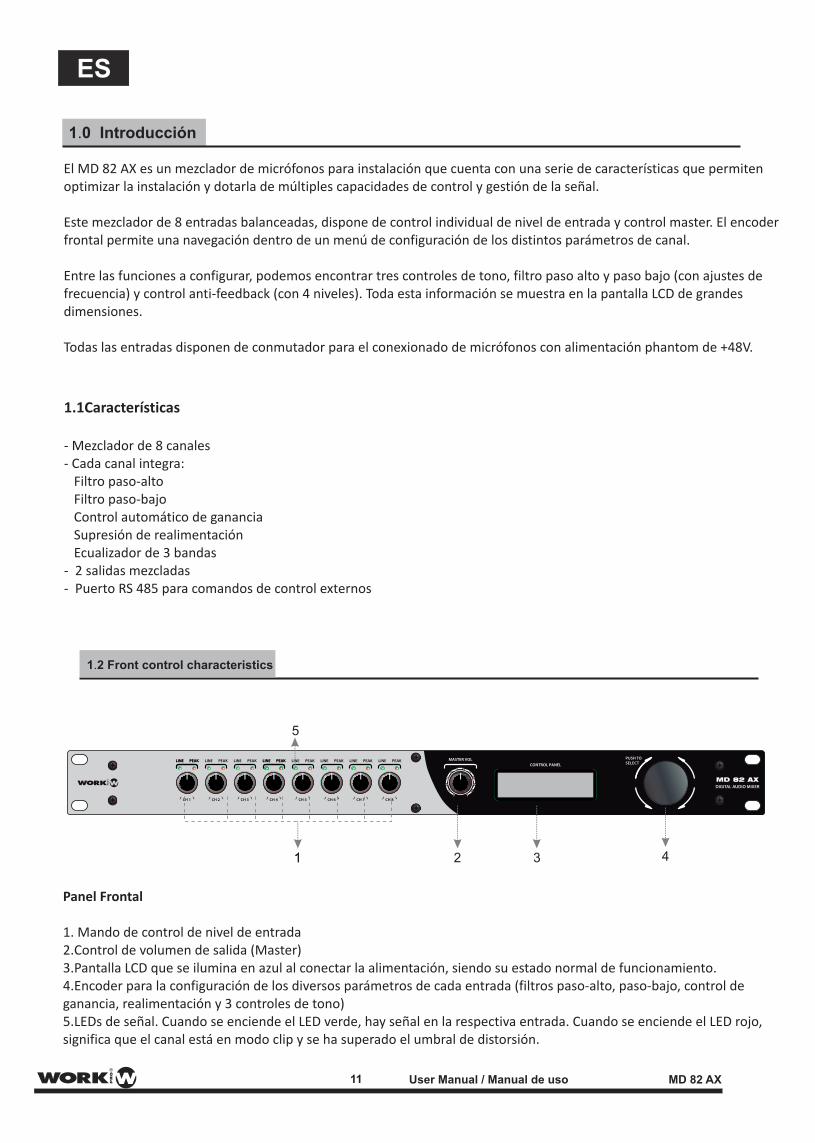
Panel Frontal
1. Mando de control de nivel de entrada2.Control de volumen de salida (Master)3.Pantalla LCD que se ilumina en azul al conectar la alimentación, siendo su estado normal de funcionamiento.4.Encoder para la configuración de los diversos parámetros de cada entrada (filtros paso-alto, paso-bajo, control de ganancia, realimentación y 3 controles de tono)5.LEDs de señal. Cuando se enciende el LED verde, hay señal en la respectiva entrada. Cuando se enciende el LED rojo, significa que el canal está en modo clip y se ha superado el umbral de distorsión.
11 User Manual / Manual de uso MD 82 AX
ES
ON OFF ON OFF ON OFF ON OFF
CH5 CH4 CH3 CH2 CH1OUT1 OUT2 MIXING CH8 CH7 CH6
GG G G G G G G G G G
48V 48V 48V 48V
1.3 Panel trasero
2.0 Configuración
1 2 3 4 5
6
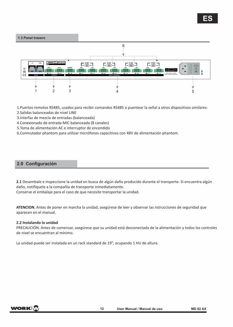
1.Puertos remotos RS485, usados para recibir comandos RS485 o puentear la señal a otros dispositivos similares-2.Salidas balanceadas de nivel LINE3.Interfaz de mezcla de entradas (balanceada)4.Conexionado de entrada MIC balanceada (8 canales) 5.Toma de alimentación AC e interruptor de encendido6.Conmutador phantom para utilizar micrófonos capacitivos con 48V de alimentación phantom.
2.1 Desembale e inspeccione la unidad en busca de algún daño producido durante el transporte. Si encuentra algún daño, notifíquelo a la compañía de transporte inmediatamente.Conserve el embalaje para el caso de que necesite transportar la unidad.
ATENCION. Antes de poner en marcha la unidad, asegúrese de leer y observar las nstrucciones de seguridad que aparecen en el manual.
2.2 Instalando la unidadPRECAUCIÓN. Antes de comenzar, asegúrese que su unidad está desconectada de la alimentación y todos los controles de nivel se encuentran al mínimo.
La unidad puede ser instalada en un rack standard de 19”, ocupando 1 HU de altura.
12 User Manual / Manual de uso MD 82 AX
ES
2.3 Eligiendo el cable y los conectores
Figura 2.3 Cableado de entrada y salida
2.4 Cableando su sistema de audio
Figura 2.4
FUENTE DEAUDIO
ON OFF
FUENTE DEAUDIO
ON OFFFUENTE DEAUDIO
CONECTORES EUROBLOCKDE ENTRADA
LINEAS DESBALANCEADAS
CONECTOR DE SALIDA
LINEAS BALANCEADAS
ON OFF ON OFF ON OFF ON OFF
CH5 CH4 CH3 CH2 CH1OUT1 OUT2 MIXING CH8 CH7 CH6
GG G G G G G G G G G
48V 48V 48V 48V
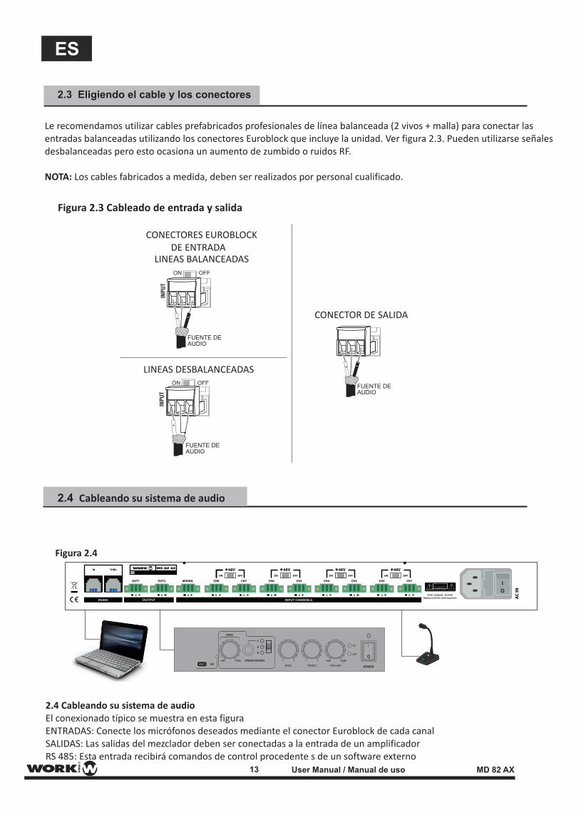
Le recomendamos utilizar cables prefabricados profesionales de línea balanceada (2 vivos + malla) para conectar las entradas balanceadas utilizando los conectores Euroblock que incluye la unidad. Ver figura 2.3. Pueden utilizarse señales desbalanceadas pero esto ocasiona un aumento de zumbido o ruidos RF.
NOTA: Los cables fabricados a medida, deben ser realizados por personal cualificado.
2.4 Cableando su sistema de audioEl conexionado típico se muestra en esta figuraENTRADAS: Conecte los micrófonos deseados mediante el conector Euroblock de cada canalSALIDAS: Las salidas del mezclador deben ser conectadas a la entrada de un amplificadorRS 485: Esta entrada recibirá comandos de control procedente s de un software externo
13 User Manual / Manual de uso MD 82 AX
ES
2.5 Conectando la alimentación AC
2.6 Puesta en marcha
3.0 Automixer (Explicación)
Utilice el siguiente procedimiento para poner en marcha su sistema:
1.Pase al mínimo todos los controles de nivel de su fuente de audio2.Haga lo mismo con los controles del amplificador3.Ponga en marcha el mezclador. La pantalla se encenderá4.Encienda el amplificado conectado a la salida del mezclador5.Suba el nivel de la fuente de audio a un valor óptimo6.Suba el nivel de mezclador a un valor óptimo7.Suba el control de nivel del amplificador hasta logra el nivel de potencia deseado
Si necesita recablear o realizar cualquier modificación en la instalación, no olvide desconectar el cable de alimentación.
NOTA. Para evitar picos de ruido al poner en marcha su sistema, es recomendable que el amplificador utilizador para manejar los altavoces, se apague antes que cualquier otro componente del sistema.
Conecte su mezclador a una toma de alimentación mural con el cable de alimentación incorporado. Primero conecte la toma IEC en la entrada del mezclador y luego el conector schucko en la toma mural.
AVISO. El tercer terminal es la toma de tierra y es un elemento importante de seguridad. No trate de deshabilitarlo.
Este funcionalidad permite configurar un valor (TARGET) marcado como el máximo nivel de un canal, y otro parámetro
(GAIN), el cual marca la cantidad de amplificación que el canal necesita alcanzar el valor TARGET. Esta funcionalidad
proporciona varias configuraciones de acuerdo a los requerimientos de la instalación.
Una opción puede ser el configurar el mismo umbral de TARGET en todos los canales con el fin de que todos los
micrófonos tengan el mismo nivel.
Otra opción será el configurar varios valores TARGET en cada canal con el fin de que esos canales tengan
preponderancia sobre el resto.
14 User Manual / Manual de uso MD 82 AX
ES
3.3 Control RS485 control
Alimentación phantom (48V) puede ser apliciada a todas las entradas de micrófono activando el control phantom
La unidad puede ser controlada mediante este puerto y los comandos marcados para ello .
3.2 Alimentación Phantom
4. Datos Técnicos
Mezclador de 8 canales de micrófono
Dimensiones / Peso / Alimentación
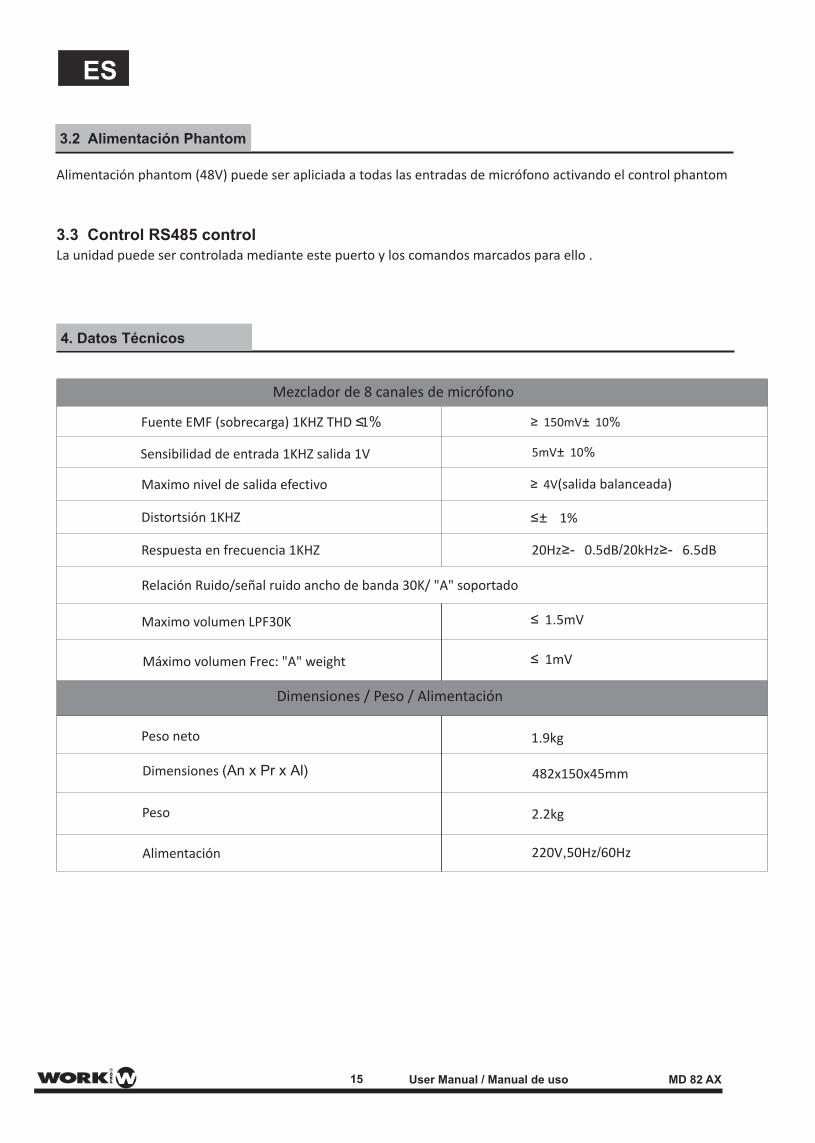
Peso neto 1.9kg
482x150x45mm
2.2kg
220V,50Hz/60Hz
Dimensiones (An x Pr x Al)
Peso
Alimentación
Fuente EMF (sobrecarga) 1KHZ THD ≤1%
Sensibilidad de entrada 1KHZ salida 1V
Maximo nivel de salida efectivo
Distortsión 1KHZ
Respuesta en frecuencia 1KHZ
Relación Ruido/señal ruido ancho de banda 30K/ "A" soportado
Maximo volumen LPF30K
Máximo volumen Frec: "A" weight
≥ 150mV± 10%
≥ 4V(salida balanceada)
20Hz≥- 0.5dB/20kHz≥- 6.5dB
≤± 1%
≤ 1.5mV
≤ 1mV
5mV± 10%
15 User Manual / Manual de uso MD 82 AX
ES
AJUSTE VOLUMEN
DATA HEAD PARITY bit Channel Number ID Number Vacio Parameter Range Vacio Vacio Vacio Data Tail
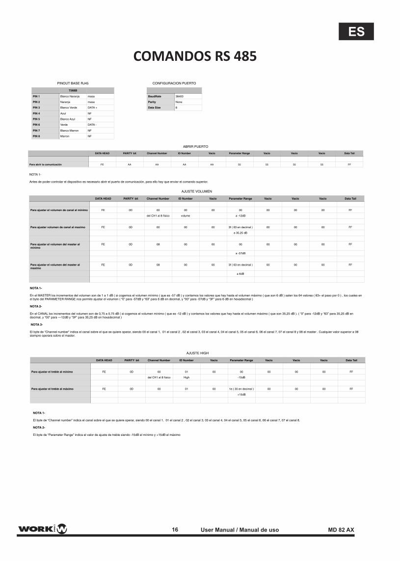
Para ajustar el volumen de canal al mínimo FE 0D 00 00 00 00 00 00 00 FF
del CH1 al 8 físico volume a -12dB
Para ajustar volumen de canal al maximo FE 0D 00 00 00 3f ( 63 en decimal ) 00 00 00 FF
a 35,25 dB
Para ajustar el volumen del master al mínimo
FE 0D 08 00 00 00 00 00 00 FF
a -57dB
Para ajustar el volumen del master al maximo
FE 0D 08 00 00 3f ( 63 en decimal ) 00 00 00 FF
a 6dB
PINOUT BASE RJ45
T568B
PIN 1 Blanco Naranja masa
PIN 2 Naranja masa
PIN 3 Blanco Verde DATA +
PIN 4 Azul NF
PIN 5 Blanco Azul NF
PIN 6 Verde DATA -
PIN 7 Blanco Marron NF
PIN 8 Marron NF
NOTA 1-
En el MASTER los incrementos del volumen son de 1 a 1 dB ( si cogemos el volumen mínimo ( que es -57 dB ) y contamos los valores que hay hasta el volumen máximo ( que son 6 dB ) salen los 64 valores ( 63+ el paso por 0 ) , los cuales en el byte del PARAMETER RANGE nos permite ajustar el volumen ( “0” para -57dB y “63” para 6 dB en decimal, y “00” para -57dB y “3F” para 6 dB en hexadecimal )
NOTA 2-
En el CANAL los incrementos del volumen son de 0,75 a 0,75 dB ( si cogemos el volumen mínimo ( que es -12 dB ) y contamos los valores que hay hasta el volumen máximo ( que son 35,25 dB ). ( “0” para -12dB y “63” para 35,25 dB en decimal, y “00” para —12dB y “3F” para 35,25 dB en hexadecimal )
NOTA 3-
El byte de “Channel number” indica el canal sobre el que se quiere operar, siendo 00 el canal 1, 01 el canal 2 , 02 el canal 3, 03 el canal 4, 04 el canal 5, 05 el canal 6, 06 el canal 7, 07 el canal 8 y 08 el master . Cualquier valor superior a 08 siempre operara sobre el master.
ABRIR PUERTO
DATA HEAD PARITY bit Channel Number ID Number Vacio Parameter Range Vacio Vacio Vacio Data Tail
Para abrir la comunicación FE AA AA AA AA 55 55 55 55 FF
CONFIGURACION PUERTO
BaudRate 38400
Parity None
Data Size 8
AJUSTE HIGH
DATA HEAD PARITY bit Channel Number ID Number Vacio Parameter Range Vacio Vacio Vacio Data Tail
Para ajustar el treble al mínimo FE 0D 00 01 00 00 00 00 00 FF
del CH1 al 8 físico High -15dB
Para ajustar el treble al máximo FE 0D 00 01 00 1e ( 30 en decimal ) 00 00 00 FF
+15dB
NOTA 1-
Antes de poder controlar el dispositivo es necesario abrir el puerto de comunicación, para ello hay que enviar el comando superior.
NOTA 1-
El byte de “Channel number” indica el canal sobre el que se quiere operar, siendo 00 el canal 1, 01 el canal 2 , 02 el canal 3, 03 el canal 4, 04 el canal 5, 05 el canal 6, 06 el canal 7, 07 el canal 8.
NOTA 2-
El byte de “Parameter Range” indica el valor de ajuste de treble siendo -15dB el mínimo y +15dB el máximo
16 User Manual / Manual de uso MD 82 AX
ES
COMANDOS RS 485
DATA HEAD PARITY bit Channel Number ID Number
Para ajustar el middle al minima FE 0D 00
del CH1 al 8 físico middle
Para ajustar el middle al maximo FE 0D 00
DATA HEAD PARITY bit Channel Number ID Number
Para ajustar el Bass al minimo FE 0D 00
del CH1 al 8 físico bass
Para ajustar el Bass al maximo FE 0D 00
DATA HEAD PARITY bit Channel Number ID Number
NOTA 1-
El byte de “Channel number” indica el canal sobre el que se quiere operar, siendo 00 el canal 1, 01 el canal 2 , 02 el canal 3, 03 el canal 4, 04 el canal 5, 05 el canal 6, 06 el canal 7, 07 el canal 8.
NOTA 2-
El byte de “Parameter Range” indica el valor de ajuste de middle siendo -15dB el mínimo y +15dB el máximo
NOTA 1-
El byte de “Channel number” indica el canal sobre el que se quiere operar, siendo 00 el canal 1, 01 el canal 2 , 02 el canal 3, 03 el canal 4, 04 el canal 5, 05 el canal 6, 06 el canal 7, 07 el canal 8.
NOTA 2-
El byte de “Parameter Range” indica el valor de ajuste de bass siendo -15dB el mínimo y +15dB el máximo
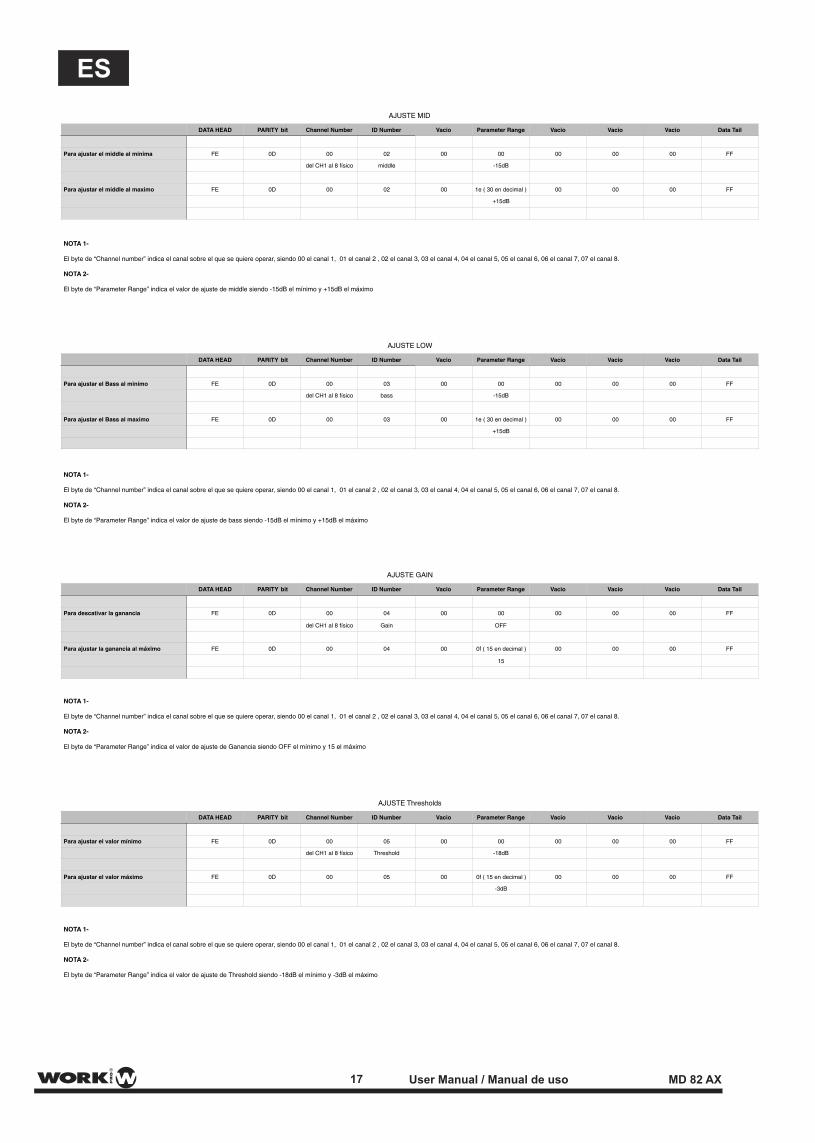
AJUSTE MID
Vacio Parameter Range Vacio Vacio Vacio Data Tail
02 00 00 00 00 00 FF
-15dB
02 00 1e ( 30 en decimal ) 00 00 00 FF
+15dB
AJUSTE LOW
Vacio Parameter Range Vacio Vacio Vacio Data Tail
03 00 00 00 00 00 FF
-15dB
03 00 1e ( 30 en decimal ) 00 00 00 FF
+15dB
AJUSTE GAIN
Vacio Parameter Range Vacio Vacio Vacio Data Tail
Para descativar la ganancia FE 0D 00 04 00 00 00 00 00 FF
del CH1 al 8 físico Gain OFF
Para ajustar la ganancia al máximo FE 0D 00 04 00 0f ( 15 en decimal ) 00 00 00 FF
15
AJUSTE Thresholds
DATA HEAD PARITY bit Channel Number ID Number Vacio Parameter Range Vacio Vacio Vacio Data Tail
Para ajustar el valor mínimo FE 0D 00 05 00 00 00 00 00 FF
del CH1 al 8 físico Threshold -18dB
Para ajustar el valor máximo FE 0D 00 05 00 0f ( 15 en decimal ) 00 00 00 FF
-3dB
NOTA 1-
El byte de “Channel number” indica el canal sobre el que se quiere operar, siendo 00 el canal 1, 01 el canal 2 , 02 el canal 3, 03 el canal 4, 04 el canal 5, 05 el canal 6, 06 el canal 7, 07 el canal 8.
NOTA 2-
El byte de “Parameter Range” indica el valor de ajuste de Ganancia siendo OFF el mínimo y 15 el máximo
NOTA 1-
El byte de “Channel number” indica el canal sobre el que se quiere operar, siendo 00 el canal 1, 01 el canal 2 , 02 el canal 3, 03 el canal 4, 04 el canal 5, 05 el canal 6, 06 el canal 7, 07 el canal 8.
NOTA 2-
El byte de “Parameter Range” indica el valor de ajuste de Threshold siendo -18dB el mínimo y -3dB el máximo
17 User Manual / Manual de uso MD 82 AX
ES
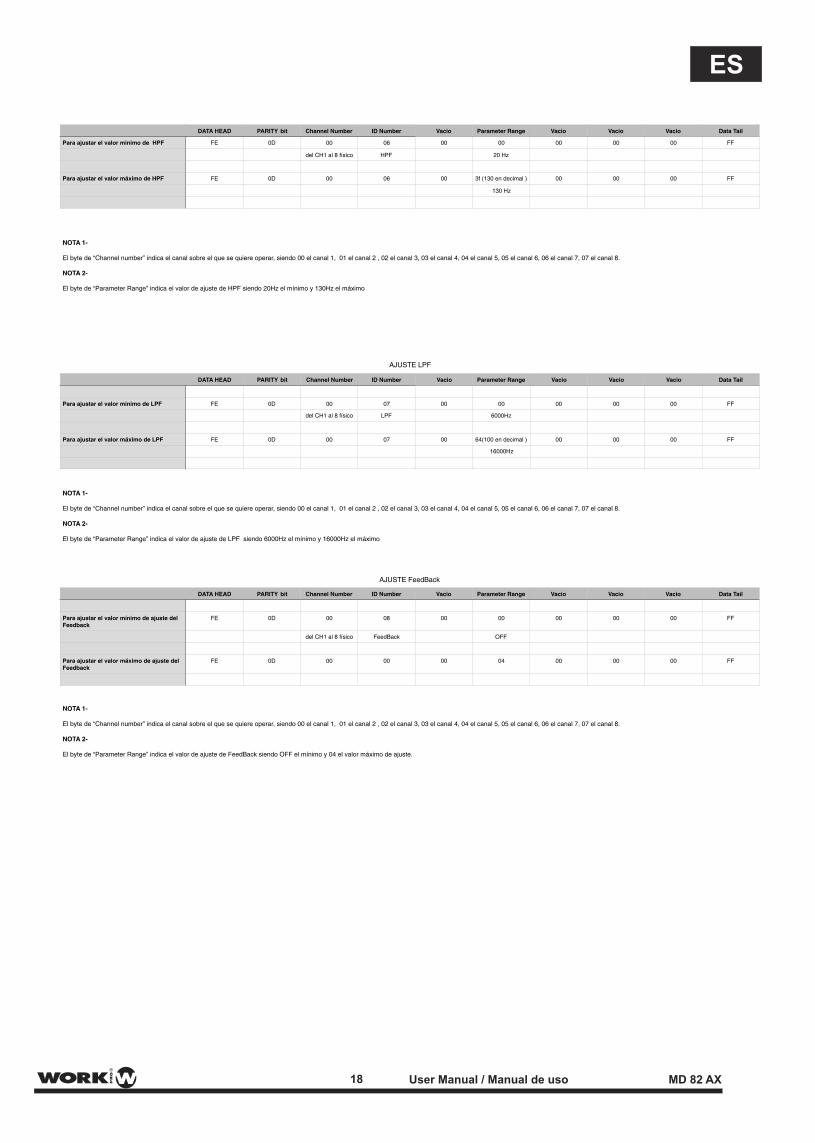
Para ajustar el valor minimo de HPF FE 0D 00 06
del CH1 al 8 físico HPF
Para ajustar el valor máximo de HPF FE 0D 00 06
DATA HEAD PARITY bit Channel Number ID Number
DATA HEAD PARITY bit Channel Number ID Number
Para ajustar el valor minimo de LPF FE 0D 00 07
del CH1 al 8 físico LPF
Para ajustar el valor máximo de LPF FE 0D 00 07
NOTA 1-
El byte de “Channel number” indica el canal sobre el que se quiere operar, siendo 00 el canal 1, 01 el canal 2 , 02 el canal 3, 03 el canal 4, 04 el canal 5, 05 el canal 6, 06 el canal 7, 07 el canal 8.
NOTA 2-
El byte de “Parameter Range” indica el valor de ajuste de HPF siendo 20Hz el mínimo y 130Hz el máximo
NOTA 1-
El byte de “Channel number” indica el canal sobre el que se quiere operar, siendo 00 el canal 1, 01 el canal 2 , 02 el canal 3, 03 el canal 4, 04 el canal 5, 05 el canal 6, 06 el canal 7, 07 el canal 8.
NOTA 2-
El byte de “Parameter Range” indica el valor de ajuste de LPF siendo 6000Hz el mínimo y 16000Hz el máximo
00 00 00 00 00 FF
20 Hz
00 3f (130 en decimal ) 00 00 00 FF
130 Hz
Vacio Parameter Range Vacio Vacio Vacio Data Tail
AJUSTE LPF
Vacio Parameter Range Vacio Vacio Vacio Data Tail
00 00 00 00 00 FF
6000Hz
00 64(100 en decimal ) 00 00 00 FF
16000Hz
AJUSTE FeedBack
DATA HEAD PARITY bit Channel Number ID Number Vacio Parameter Range Vacio Vacio Vacio Data Tail
Para ajustar el valor mínimo de ajuste del Feedback
FE 0D 00 08 00 00 00 00 00 FF
del CH1 al 8 físico FeedBack OFF
Para ajustar el valor máximo de ajuste del Feedback
FE 0D 00 00 00 04 00 00 00 FF
NOTA 1-
El byte de “Channel number” indica el canal sobre el que se quiere operar, siendo 00 el canal 1, 01 el canal 2 , 02 el canal 3, 03 el canal 4, 04 el canal 5, 05 el canal 6, 06 el canal 7, 07 el canal 8.
NOTA 2-
El byte de “Parameter Range” indica el valor de ajuste de FeedBack siendo OFF el mínimo y 04 el valor máximo de ajuste.
18 User Manual / Manual de uso MD 82 AX
ES

EQUIPSON, S.A.Avda. El Saler, 14 - Pol. Ind. L´Alteró,46460 - Silla (Valencia) Spain
Tel. +34 96 121 63 01 Fax + 34 96 120 02 42
www.workproaudio.com [email protected]


![DPA Create!Form MD AX DS 082012 Final[1]](https://img.pdfslide.us/doc/110x75/577c80a31a28abe054a98ede/dpa-createform-md-ax-ds-082012-final1.jpg)