Embed Size (px)
DESCRIPTION
How : The idea, the tools The code is written in ROOT in a general way. It should be configurable in a few minutes (ie create a new geometry) and run in seconds. It should be run by anybody on a laptop. It should be stand alone (no monster external libraries). Small amount of documentation.
Citation preview
McSiMBarrel Strips upgrade geometry
Steve McMahonRAL
The Aim : What am I trying to do?• Provide a tool for fast (minutes) visualization of the layout of
the upgrade strip barrel (barrel in the first instance, end-cap may come later) to answer some rudimentary questions concerning the layout.
• The things I would imagine that we will be able to provide are: module overlaps (active layers), clearances (of envelopes around modules), coverage (hole maps), momentum resolution, and their sensitivity to small changes in layout (radius, tilt angle, stereo angle) or removal of various section
• It is NOT a replacement for a CAD model or a full detector simulation.
How : The idea, the tools
• The code is written in ROOT in a general way.• It should be configurable in a few minutes (ie
create a new geometry) and run in seconds. It should be run by anybody on a laptop.
• It should be stand alone (no monster external libraries).
• Small amount of documentation.
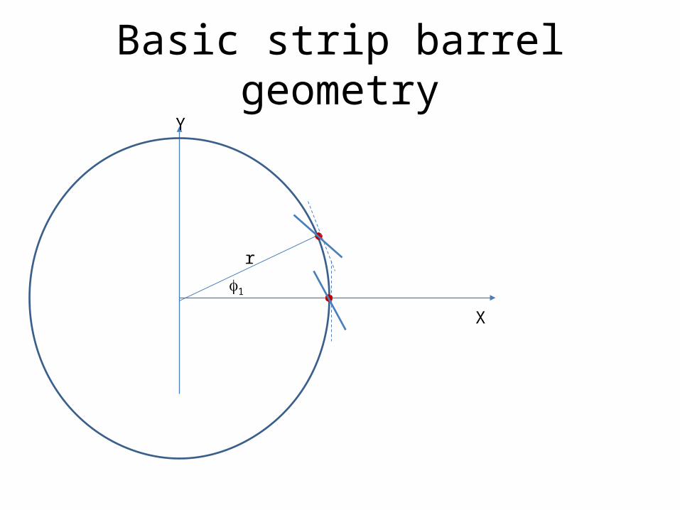
Basic strip barrel geometry
r
X
Y
f1
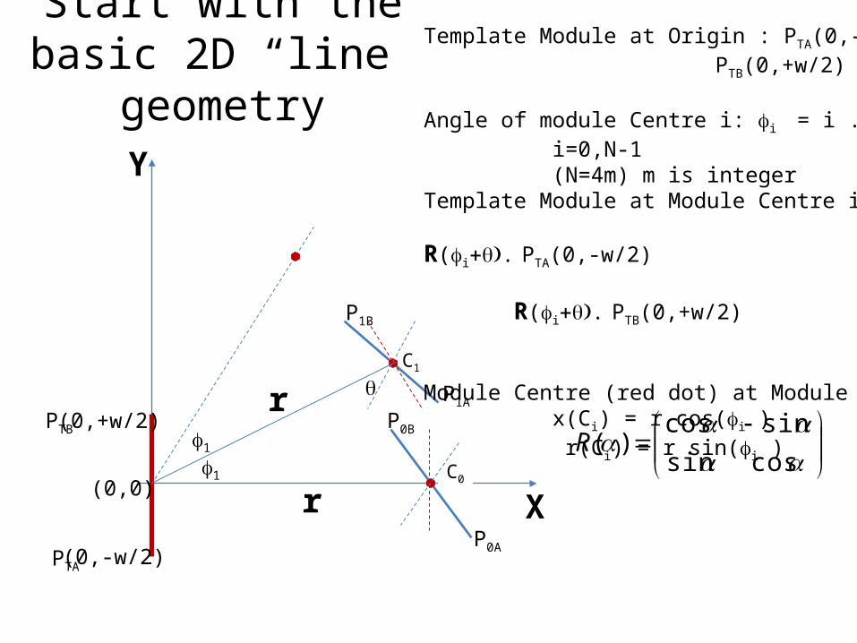
Start with thebasic 2D “line” geometry
Y
XP0A
P0B
P1A
(0,+w/2)
(0,-w/2)
(0,0)f1
qC1
C0
P1B
r
r
Template Module at Origin : PTA(0,-w/2) PTB(0,+w/2)
Angle of module Centre i: fi = i . 2p/ Ni=0,N-1 (N=4m) m is integer
Template Module at Module Centre i R(fi+q). PTA(0,-w/2) R(fi+q). PTB(0,+w/2) Module Centre (red dot) at Module Centre i
x(Ci) = r cos(fi ) r(Ci) = r sin(fi )
PTA
PTB
cossinsincos
)(Rf1
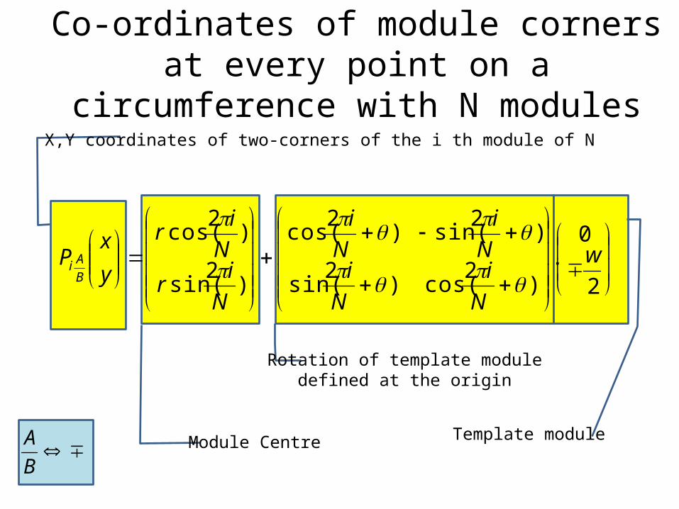
Co-ordinates of module corners at every point on a circumference with N modules
++
+++
2
0.
)2cos()2sin(
)2sin()2cos(
)2sin(
)2cos(w
Ni
Ni
Ni
Ni
NirNir
yx
PBAi
qpqp
qpqp
p
p
Module Centre
Rotation of template moduledefined at the origin
Template module
X,Y coordinates of two-corners of the i th module of N
BA
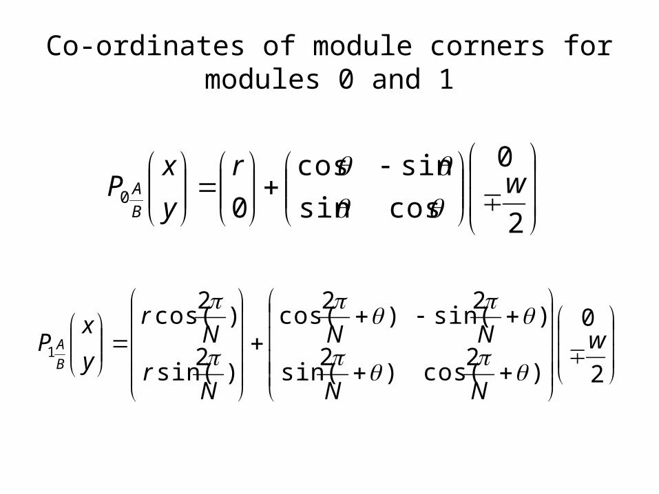
Co-ordinates of module corners formodules 0 and 1
+
2
0
cossinsincos
00 wryx
PBA qq
++
+++
2
0
)2cos()2sin(
)2sin()2cos(
)2sin(
)2cos(1 w
NN
NN
Nr
Nr
yx
PBA
qpqp
qpqp
p
p
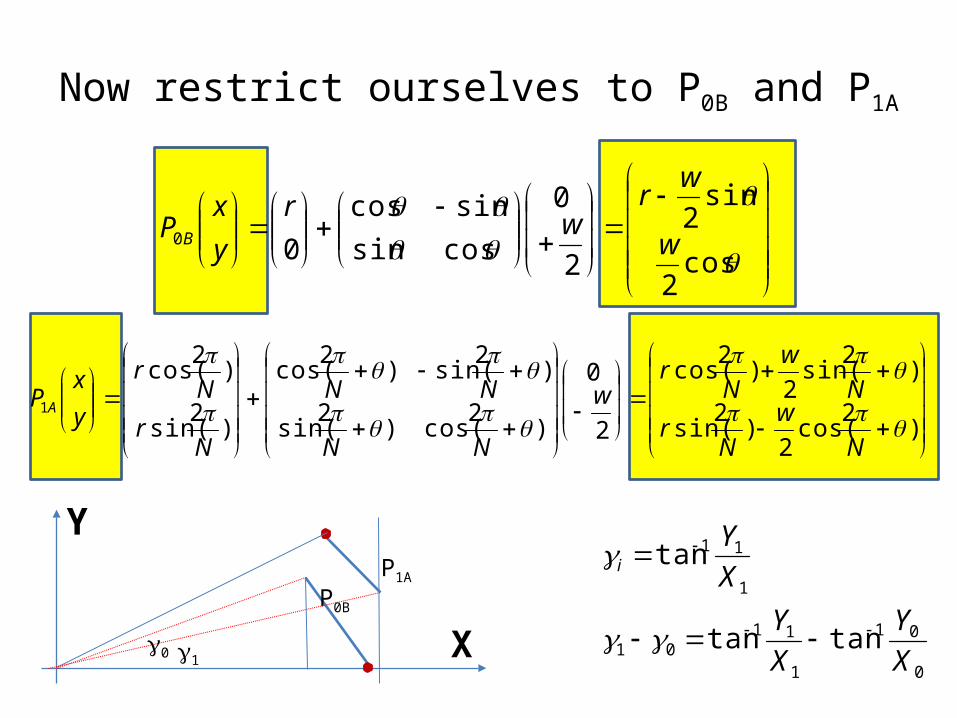
Now restrict ourselves to P0B and P1A
+
++
++
+++
)2cos(2
)2sin(
)2sin(2
)2cos(
2
0
)2cos()2sin(
)2sin()2cos(
)2sin(
)2cos(1
qpp
qpp
qpqp
qpqp
p
p
Nw
Nr
Nw
Nr
w
NN
NN
Nr
Nr
yx
P A
+
+
q
q
qqqq
cos2
sin2
2
0
cossinsincos
00 w
wrwr
yx
P B
Y
XP0B
P1A
g0 g10
01
1
1101
1
11
tantan
tan
XY
XY
XY
i
gg
g
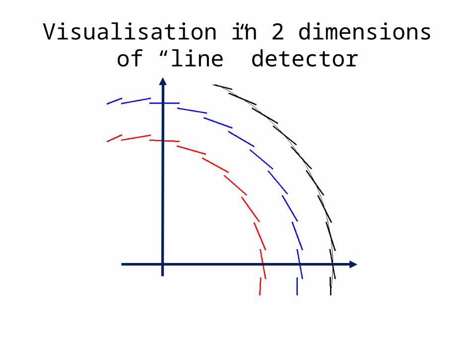
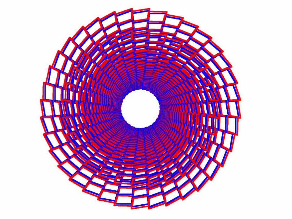
Visualisation in 2 dimensions of “line” detector
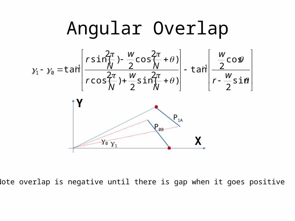
Angular Overlap
Y
XP0B
P1A
g0 g1
++
+
q
q
qpp
qpp
ggsin2
cos2tan
)2sin(2
)2cos(
)2cos(2
)2sin(tan 11
01 wr
w
Nw
Nr
Nw
Nr
Note overlap is negative until there is gap when it goes positive
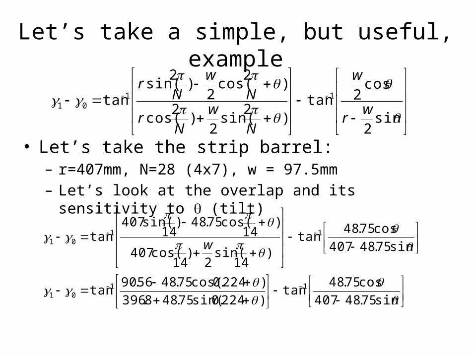
Let’s take a simple, but useful, example
• Let’s take the strip barrel: – r=407mm, N=28 (4x7), w = 97.5mm– Let’s look at the overlap and its sensitivity to q (tilt)
++
+
q
q
qpp
qpp
ggsin2
cos2tan
)2sin(2
)2cos(
)2cos(2
)2sin(tan 11
01 wr
w
Nw
Nr
Nw
Nr
+++
++
+
qqgg
qpp
qpp
gg
sin75.48407cos75.48tan
)224.0sin(75.488.396)224.0cos(75.4856.90tan
sin75.48407cos75.48tan
)14
sin(2
)14
cos(407
)14
cos(75.48)14
sin(407tan
1101
1101 w
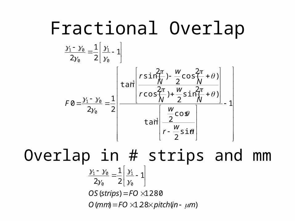
Fractional Overlap
++
+
1
sin2
cos2tan
)2sin(2
)2cos(
)2cos(2
)2sin(tan
21
20
121
2
1
1
0
01
0
1
0
01
q
q
qpp
qpp
ggg
gg
ggg
wr
wN
wN
r
Nw
Nr
F
Overlap in # strips and mm
)(28.1)(1280)(
121
2 0
1
0
01
minpitchFOmmOFOstripsOS
gg
ggg
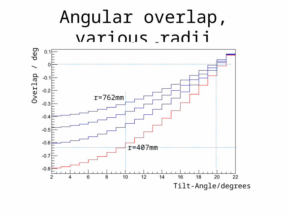
Angular overlap, various radii
r=407mm
r=762mm
Tilt-Angle/degrees
Ove
rlap
/ deg
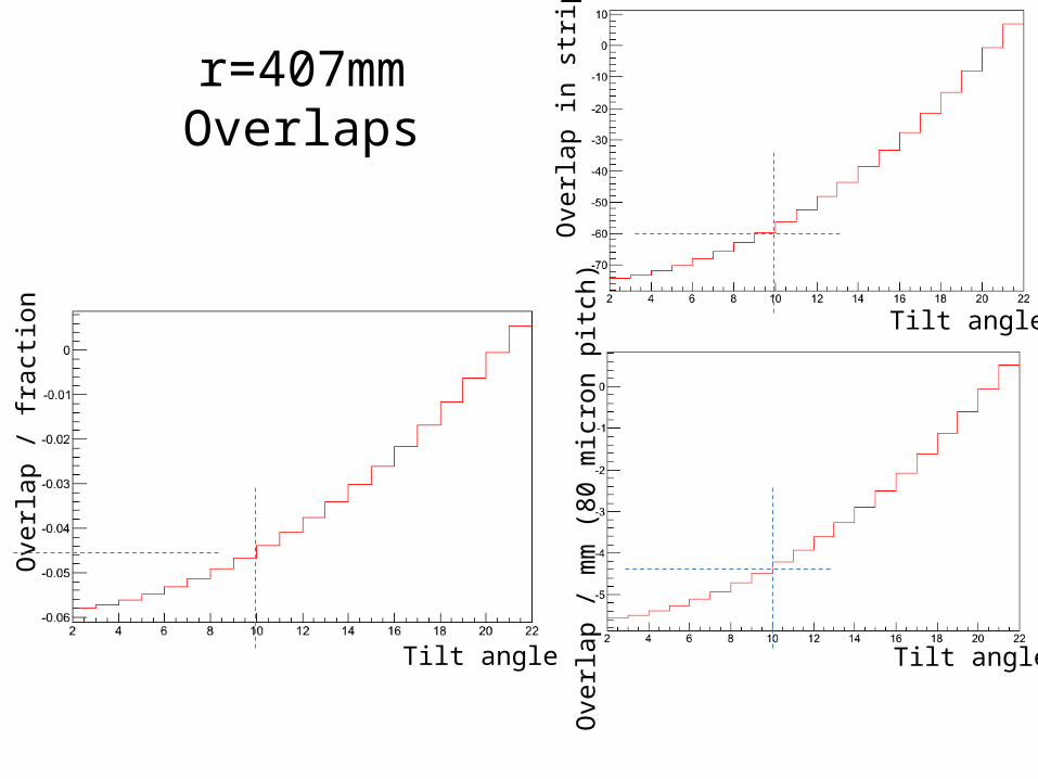
r=407mmOverlaps
Ove
rlap
/ fra
ction
Ove
rlap
/ mm
(80
mic
ron
pitc
h)O
verla
p in
strip
s
Tilt angle
Tilt angleTilt angle
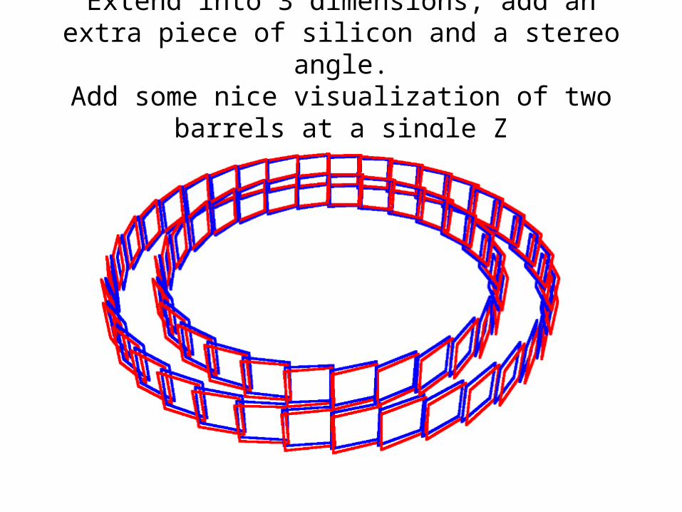
Extend into 3 dimensions, add an extra piece of silicon and a stereo angle.
Add some nice visualization of two barrels at a single Z
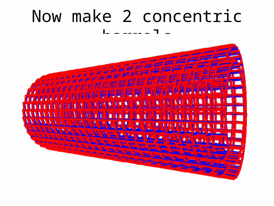
Now make 2 concentric barrels
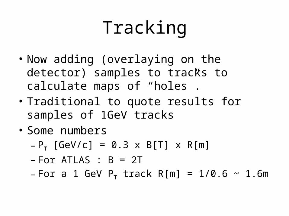
Tracking
• Now adding (overlaying on the detector) samples to tracks to calculate maps of “holes”.
• Traditional to quote results for samples of 1GeV tracks
• Some numbers– PT [GeV/c] = 0.3 x B[T] x R[m]– For ATLAS : B = 2T– For a 1 GeV PT track R[m] = 1/0.6 ~ 1.6m
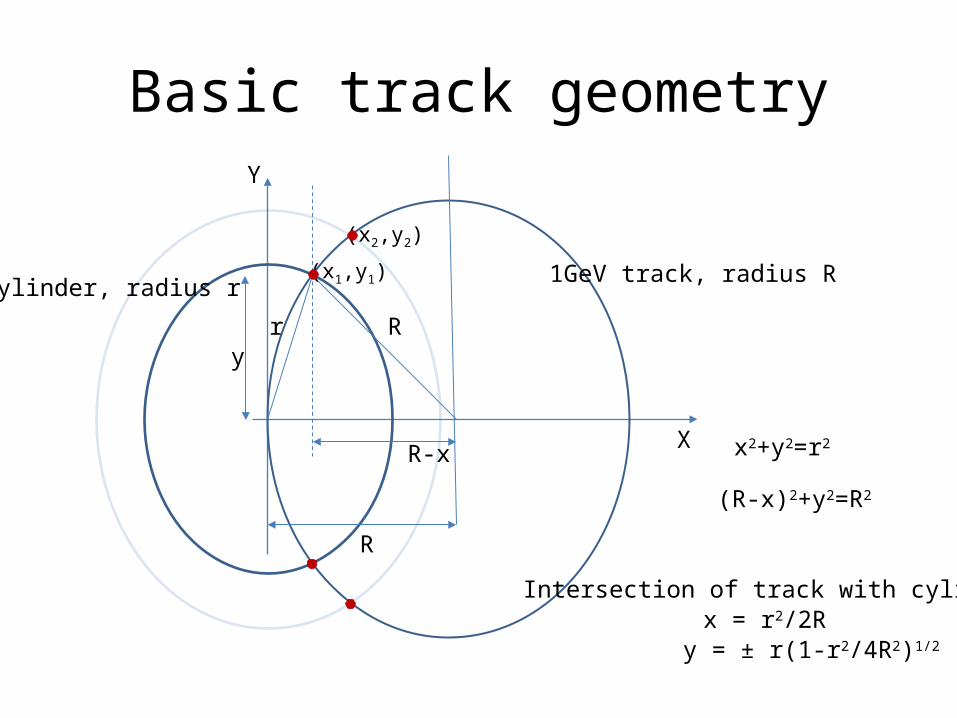
Basic track geometry
1GeV track, radius Rcylinder, radius r
r R
R
(x1,y1)
R-x
y
x2+y2=r2
(R-x)2+y2=R2
x = r2/2Ry = ± r(1-r2/4R2)1/2
(x2,y2)
Y
X
Intersection of track with cylinder
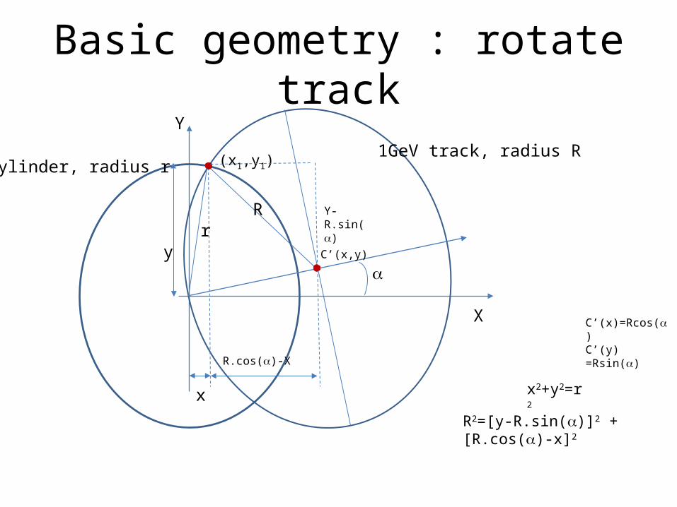
Basic geometry : rotate track
1GeV track, radius Rcylinder, radius r
r
(x1,y1)
x
y
x2+y2=r2
R
X
Y
C’(x,y)
C’(x)=Rcos()C’(y) =Rsin()
R.cos()-X
Y-R.sin()
R2=[y-R.sin()]2 + [R.cos()-x]2
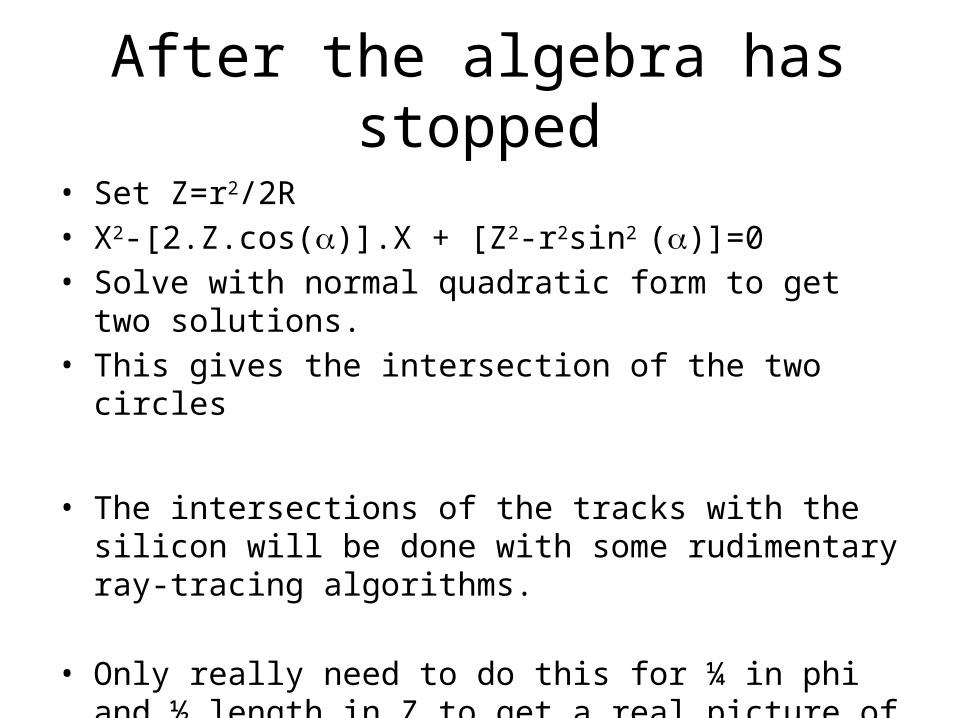
After the algebra has stopped• Set Z=r2/2R• X2-[2.Z.cos()].X + [Z2-r2sin2 ()]=0• Solve with normal quadratic form to get two solutions.• This gives the intersection of the two circles
• The intersections of the tracks with the silicon will be done with some rudimentary ray-tracing algorithms.
• Only really need to do this for ¼ in phi and ½ length in Z to get a real picture of the coverage.
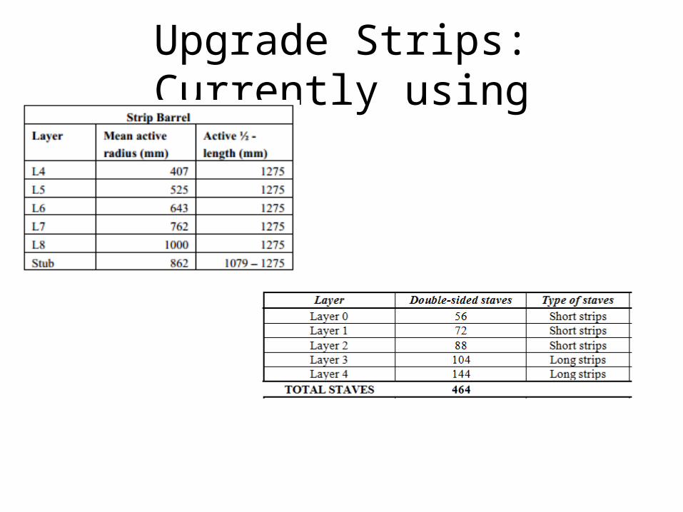
Upgrade Strips: Currently using

Conclusion• A general non-specialist tool is being developed
to answer some rudimentary questions about layout and layout evolution or changes.
• If you want something added … just ask.• Anyone can contribute…• I have a summer student (Varun Varahamurt)
working with me on this from 4th June to 10th August.