Embed Size (px)
Citation preview
7/30/2019 McI Ecoplus Tm
http://slidepdf.com/reader/full/mci-ecoplus-tm 1/32
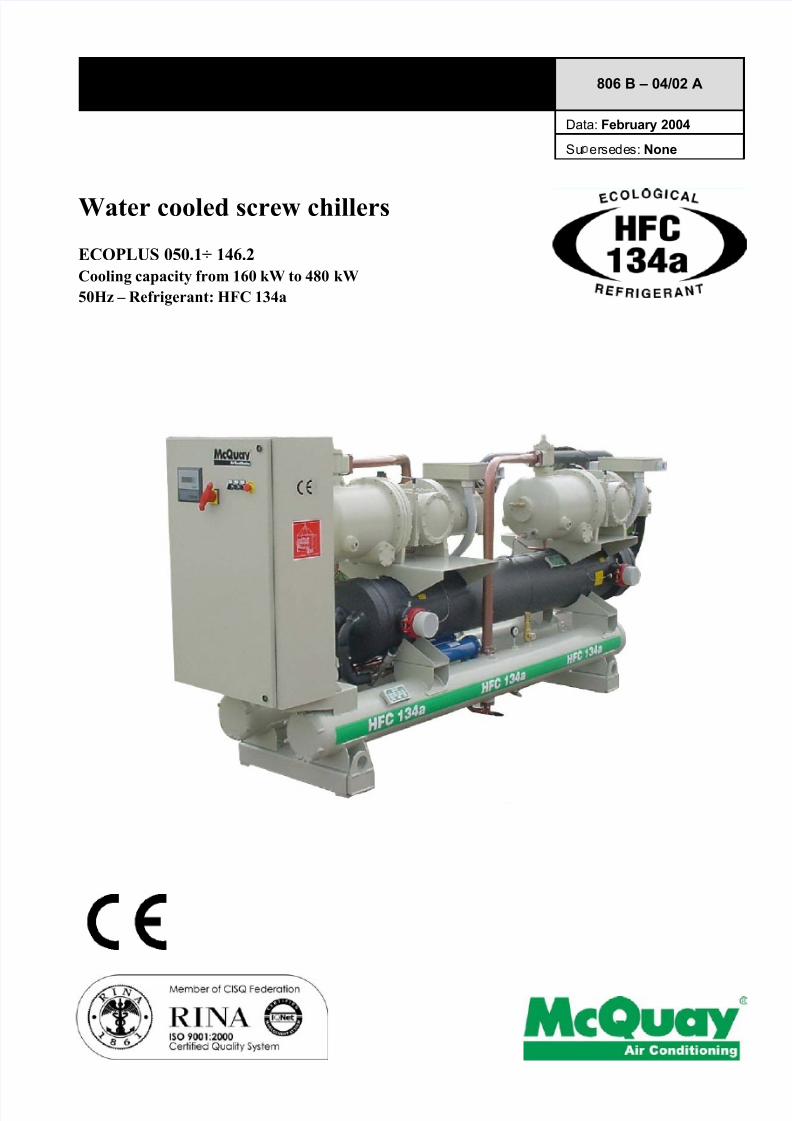
Water cooled screw chillers
ECOPLUS 050.1÷ 146.2
Cooling capacity from 160 kW to 480 kW
50Hz – Refrigerant: HFC 134a
Product Manual 806 B – 04/02 A
Data: February 2004
Su ersedes: None
7/30/2019 McI Ecoplus Tm
http://slidepdf.com/reader/full/mci-ecoplus-tm 2/32
806 B – 04/02 A – pag. 2/32
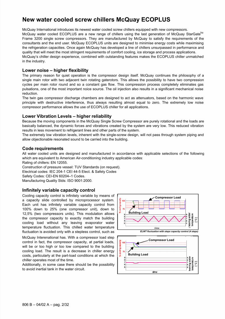
ELWT fluctuation with steps capacity control (4 steps)
NO EWLT fluctuation with McQuay stepless capacity control (4 steps)
New water cooled screw chillers McQuay ECOPLUS
McQuay International introduces its newest water cooled screw chillers equipped with new compressors.
McQuay water cooled ECOPLUS are a new range of chillers using the last generation of McQuay StarGateTM
Frame 3200 single screw compressors. They are manufactured by McQuay to satisfy the requirements of the
consultants and the end user. McQuay ECOPLUS units are designed to minimise energy costs while maximising
the refrigeration capacities. Once again McQuay has developed a line of chillers unsurpassed in performance and
quality that will meet the most stringent requirements of comfort cooling, ice storage and process applications.
McQuay’s chiller design experience, combined with outstanding features makes the ECOPLUS chiller unmatchedin the industry.
Lower noise – higher flexibilityThe primary reason for quiet operation is the compressor design itself. McQuay continues the philosophy of a
single main rotor with two adjacent twin rotating gaterotors. This allows the possibility to have two compression
cycles per main rotor round and so a constant gas flow. This compression process completely eliminates gas
pulsations, one of the most important noice source. The oil injection also results in a significant mechanical noise
reduction.
The twin gas compressor discharge chambers are designed to act as attenuators, based on the harmonic wave
principle with destructive interference, thus always resulting almost equal to zero. The extremely low noise
compressor performance allows the use of ECOPLUS chiller for all applications.
Lower Vibration Levels – higher reliabilityBecause the moving components in the McQuay Single Screw Compressor are purely rotational and the loads are
basically balanced, the dynamic forces and vibrations created by the system are very low. This reduced vibration
results in less movement to refrigerant lines and other parts of the system.
The extremely low vibration levels, inherent with the single-screw design, will not pass through system piping and
allow objectionable resonated sound to be carried into the building.
Code requirements
All water cooled units are designed and manufactured in accordance with applicable selections of the following
which are equivalent to American Air-conditioning industry applicable codes:
Rating of chillers: EN 12055.
Construction of pressure vessel: TUV Standards (on request).Electrical codes: IEC 204-1 CEI 44-5 Elect. & Safety Codes
Safety Codes: CEI-EN 60204–1 Codes.
Manufacturing Quality Stds: ISO 9001:2000.
Infinitely variable capacity controlCooling capacity control is infinitely variable by means of
a capacity slide controlled by microprocessor system.
Each unit has infinitely variable capacity control from
100% down to 25% (one compressor unit), down to
12,5% (two compressors units). This modulation allows
the compressor capacity to exactly match the building
cooling load without any leaving evaporator water temperature fluctuation. This chilled water temperature
fluctuation is avoided only with a stepless control, such as
McQuay Interenational has. With a compressor load step
control in fact, the compressor capacity, at partial loads,
will be or too high or too low compared to the building
cooling load. The result is a decrease in chiller energy
costs, particularly at the part-load conditions at which the
chiller operates most of the time.
Additionally, in some case there should be the possibility
to avoid inertial tank in the water circuit.
time
Compressor Load
Building Load
Building Load
Compressor Load
7/30/2019 McI Ecoplus Tm
http://slidepdf.com/reader/full/mci-ecoplus-tm 3/32
806 B – 04/02 A – pag. 3/32
Unmatched serviceabilityField serviceability has not been sacrificed. Inspection covers allows visual inspection of the main screw and
gaterotors.
Outstanding reliability featuresUnsurpassed Efficiency
• Zero clearance fit between the two gaterotors and main screw rotor virtually eliminates leakage between
the high and low-pressure sides during compression. Special gaterotor material made from an advanced
composite, temperature stable material makes a zero clearance design possible.
• The McPower air-cooled chiller is equipped with the most advanced means of refrigerant flow control
available. An electronic expansion valve coupled with the MicroTech II C Plus controller's control logic
provides excellent operating efficiencies both at full and part load operation.
• Infinite unloading matches compressor capacity to load.
• Full factory testing of the unit with water hookups helps provides a trouble-free start-up. Extensive quality
control checks during testing means that each equipment protection and operating control is properly
adjusted and operates correctly before it leaves the factory. Factory-installed options minimize field
expenses and startup labor.
• The rugged design of the single-screw compressor allows it to be tolerant of liquid slugging. McPower
screw chiller will start and operate under conditions that would often destroy other compressors.
• Very low loading enhances the bearing and compressor reliability. Due to symmetrical compression
taking place on both sides of the main screw rotor, balanced forces result in the elimination of the large
radial force loads inherent in twin-screw compressors.
• Integral to the basic design of the single-screw compressor, the main screw rotor shaft and the gaterotor
shafts cross at right angles in the compressor. The result is ample space to locate heavy duty bearings
and increase compressor reliability since no limitations are placed on bearing design as found in twin-
screw compressors.
General characteristics
StructureThe chiller is equipped with brackets directly installed on heat exchangers. The evaporator and the suction piping
are appropriately insulated to prevent condensation. Unit is provided with lifting holes.
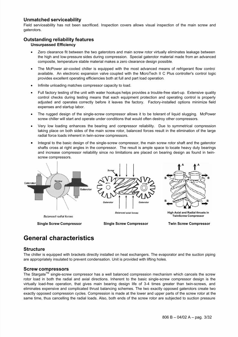
Screw compressorsThe Stargate
TMsingle-screw compressor has a well balanced compression mechanism which cancels the screw
rotor load in both the radial and axial directions. Inherent to the basic single-screw compressor design is the
virtually load-free operation, that gives main bearing design life of 3-4 times greater than twin-screws, and
eliminates expensive and complicated thrust balancing schemes. The two exactly opposed gaterotors create two
exactly opposed compression cycles. Compression is made at the lower and upper parts of the screw rotor at thesame time, thus cancelling the radial loads. Also, both ends of the screw rotor are subjected to suction pressure
Screw
Gaterotor Gaterotor
A
B
BB
B
AA
B
BB
B
A
High Axial and Radial thrusts inTwinScrew Compressor
Single Screw Compressor Single Screw Compressor Twin Screw Compressor
7/30/2019 McI Ecoplus Tm
http://slidepdf.com/reader/full/mci-ecoplus-tm 4/32
806 B – 03/05 H – pag. 4/32
Zeotropic refrigerant
as HFC 407CAzeotropic refrigerant
as HFC 134a
only, which cancels the axial loads and eliminates the huge thrust loads inherent in twin-screw compressors (see
images and drawings in this page).
Oil injection is used for these compressors in order to get high COP at high condensing pressure. The oil supplied
to the compressor performs three basic functions: oil for capacity control actuation, oil for bearing lubrication, oil for
sealing. The oil is injected via fixed ports in the casing around the rotor.
Compressors have an infinitely variable capacity control down to 25% of its total capacity. This control is made by
means of capacity slides controlled by microprocessors.
The compressor is furnished with an integrated high efficiency oil separator to maximise oil extraction.
The compressor is provided with a liquid injection circuit to reach high sealing and oil cooling.Standard start is star-delta type; Soft start type is available (as option) in order to have lower inrush current in
almost all work conditions and to provide smooth, slow stepless acceleration and controlled slow deceleration
reducing mechanical and electrical stress for even greater compressor/motor life.
Ecological HFC 134a refrigerantMcQuay has designed and optimized new Stargate
TMcompressors to operate with HFC 134a, ecological
refrigerant with zero ODP (Ozone Depletion Potential) and very low GWP (Global Warming Potential) that means
low value of the “direct effect” in the formula of TEWI (Total Equivalent Warming Impact).
The HFC 134a refrigerant cycle has very good thermodinamic efficiency and pressure values for the condensing
section are very low. This means less stress for the mechanical moving parts of the compressor and therefore a
higher reliability for it. Also the discharge gas temperature is low thanks to using of this refrigerant; this means
better performance for shell and tube condenser and always very good working condition for the oil.
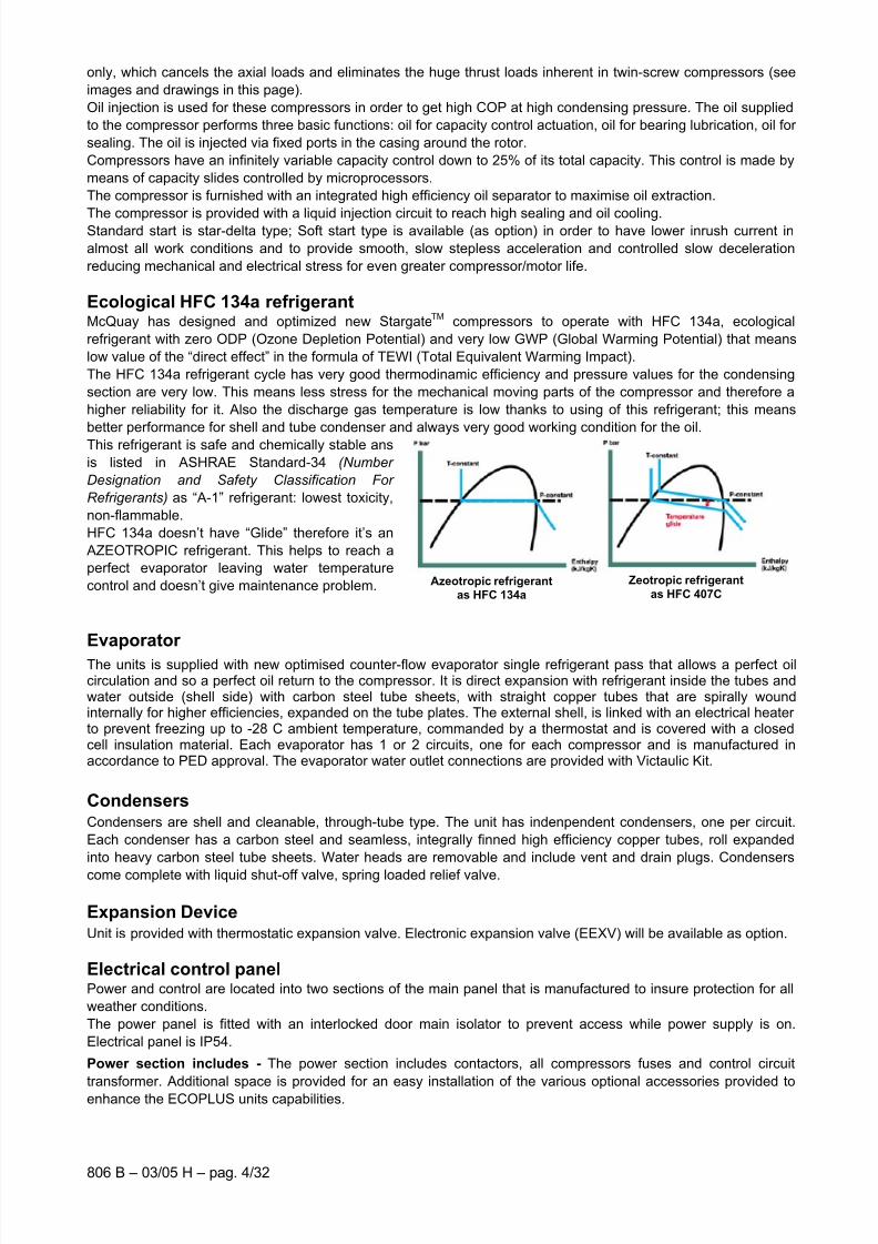
This refrigerant is safe and chemically stable ans
is listed in ASHRAE Standard-34 (Number
Designation and Safety Classification For
Refrigerants) as “A-1” refrigerant: lowest toxicity,
non-flammable.
HFC 134a doesn’t have “Glide” therefore it’s an
AZEOTROPIC refrigerant. This helps to reach a
perfect evaporator leaving water temperature
control and doesn’t give maintenance problem.
Evaporator
The units is supplied with new optimised counter-flow evaporator single refrigerant pass that allows a perfect oilcirculation and so a perfect oil return to the compressor. It is direct expansion with refrigerant inside the tubes andwater outside (shell side) with carbon steel tube sheets, with straight copper tubes that are spirally woundinternally for higher efficiencies, expanded on the tube plates. The external shell, is linked with an electrical heater to prevent freezing up to -28 C ambient temperature, commanded by a thermostat and is covered with a closedcell insulation material. Each evaporator has 1 or 2 circuits, one for each compressor and is manufactured inaccordance to PED approval. The evaporator water outlet connections are provided with Victaulic Kit.
CondensersCondensers are shell and cleanable, through-tube type. The unit has indenpendent condensers, one per circuit.
Each condenser has a carbon steel and seamless, integrally finned high efficiency copper tubes, roll expanded
into heavy carbon steel tube sheets. Water heads are removable and include vent and drain plugs. Condensers
come complete with liquid shut-off valve, spring loaded relief valve.
Expansion DeviceUnit is provided with thermostatic expansion valve. Electronic expansion valve (EEXV) will be available as option.
Electrical control panelPower and control are located into two sections of the main panel that is manufactured to insure protection for all
weather conditions.
The power panel is fitted with an interlocked door main isolator to prevent access while power supply is on.
Electrical panel is IP54.
Power section includes - The power section includes contactors, all compressors fuses and control circuit
transformer. Additional space is provided for an easy installation of the various optional accessories provided to
enhance the ECOPLUS units capabilities.
7/30/2019 McI Ecoplus Tm
http://slidepdf.com/reader/full/mci-ecoplus-tm 5/32
806 B – 04/02 A – pag. 5/32
Certifications All the ECOPLUS units are CE marked (89/392). McQuay Italia obtained ISO 9001 certification in 1997.
Water content in cooling circuitsThe cooled water distribution circuits should have a minimum water content to avoid excessive compressors start
and stop.
In fact, each time the compressor starts up, an excessive quantity of oil goes from the compressor sump and
simultaneously there is a rise in the temperature of the compressor motor’s stator due to the inrush current during
the start-up. To prevent damage to the compressors, McQuay has envisaged the application of a device to limitfrequent stops and restarts.
During the span of one hour there will be no more than 6 starts of the compressor. The plant side should therefore
ensure that the overall water content allows a more constant functioning of the unit and consequently greater
environmental comfort. The minimum installation water content envisaged should be calculated with a certain
approximation using this simplified formula:
(1) Q = 35,83 X)C(T
(kW)P
°∆X
N
1
where:
Q = Minimum content of the plant expressed in litres
P = Cooling capacity of the plant expressed in kW∆T = Entering/leaving water temperature difference of the evaporator expressed in °C
N = Number of compressors.
This should be the minimum quantity of water through the chiller in each operating condition, also when
therminal hydronic units are switched off.
Therefore for a more accurate determination of the water quantity, it is advisable to contact the designer of the
plant.

7/30/2019 McI Ecoplus Tm
http://slidepdf.com/reader/full/mci-ecoplus-tm 6/32
806 B – 03/05 H – pag. 6/32
MicroTech II C Plus controller
MicroTech II C Plus controller is installed as standard on all the units; it can be used to modify unit set points and
check control parameters. A display illustrates the machine's operating status, programable values and setpoints
e.g. temperatures, and pressures of fluids (water, refrigerant). Device controls maximise the McQuay chillers
energy efficiency and reliability characteristics. It uses sophisticated software with predictive logic to select the
most energy efficient combination of compressor, expansion device and condenser fan to keep stable operating
conditions and maximise energy efficiency. The compressors are automatically rotated to ensure equal operating
hours. MicroTech II C Plus protects critical components in response to external signals from its system sensors
measuring: motor temperatures, refrigerant gas and oil pressures, correct phases sequence and phase loss.
Control section - main features:
• Chillers enabled to work in partial failure condition thanks to the distributed multiprocessor logic system
• Full routine operation at condition of:
- High ambient temperature value
- High thermal load
- High evaporator entering water temperature (start-up)
• Display of evaporator entering/leaving water temperature
• Display of condensing-evaporating temperature and pressure, suction and discharge superheat temperature
for each circuit
• Leaving water cooled temperature regulation. Temperature tolerance ± 0,1°C
• Compressors and evaporator/condenser pumps hours counter
• Display of Status Safety Devices
• Start up numbers and compressors working hours equalization
• Excellent management of compressors load
• Cooling tower’s fans management according to condensing pressure
• Automatic re-start in case of power supply interruption (adjustable)
• Soft Load
• Return Reset
• AOT Reset (optional)
• Setpoint Reset (optional)
• Demand limit or Current limit (optional)
Safety for each refrigerant circuit
High pressure (pressure switch)
Compressor overload (optional)
High Discharge Temperature on the compressor
Phase Monitor
Star / Delta Transition Failed
Low Delta Pressure between Suction and Discharge
Low pressure ratio
High oil pressure drop
Low oil pressure
System security
Phase monitor
Freeze protection
An evaporator’s flow controller input (stops the unit)
Remote on/off input.
7/30/2019 McI Ecoplus Tm
http://slidepdf.com/reader/full/mci-ecoplus-tm 7/32
806 B – 04/02 A – pag. 7/32
Regulation typeProportional + integral + derivative regulation on the input probe of the evaporator water leaving temperature.
MicroTech II C Plus terminal
The MicroTech II C Plus terminal has following features:
• 4-lines by 20-character liquid crystal display back lighted
• Key-pad consisting of 15 keys “ clear language display ”• Memory to protect the data
• General faults alarm led
• 4-level password access to modify the setting
• Service report displaying all running hours and general conditions
• Memorized alarm history to facilitate the fault’s analysis.
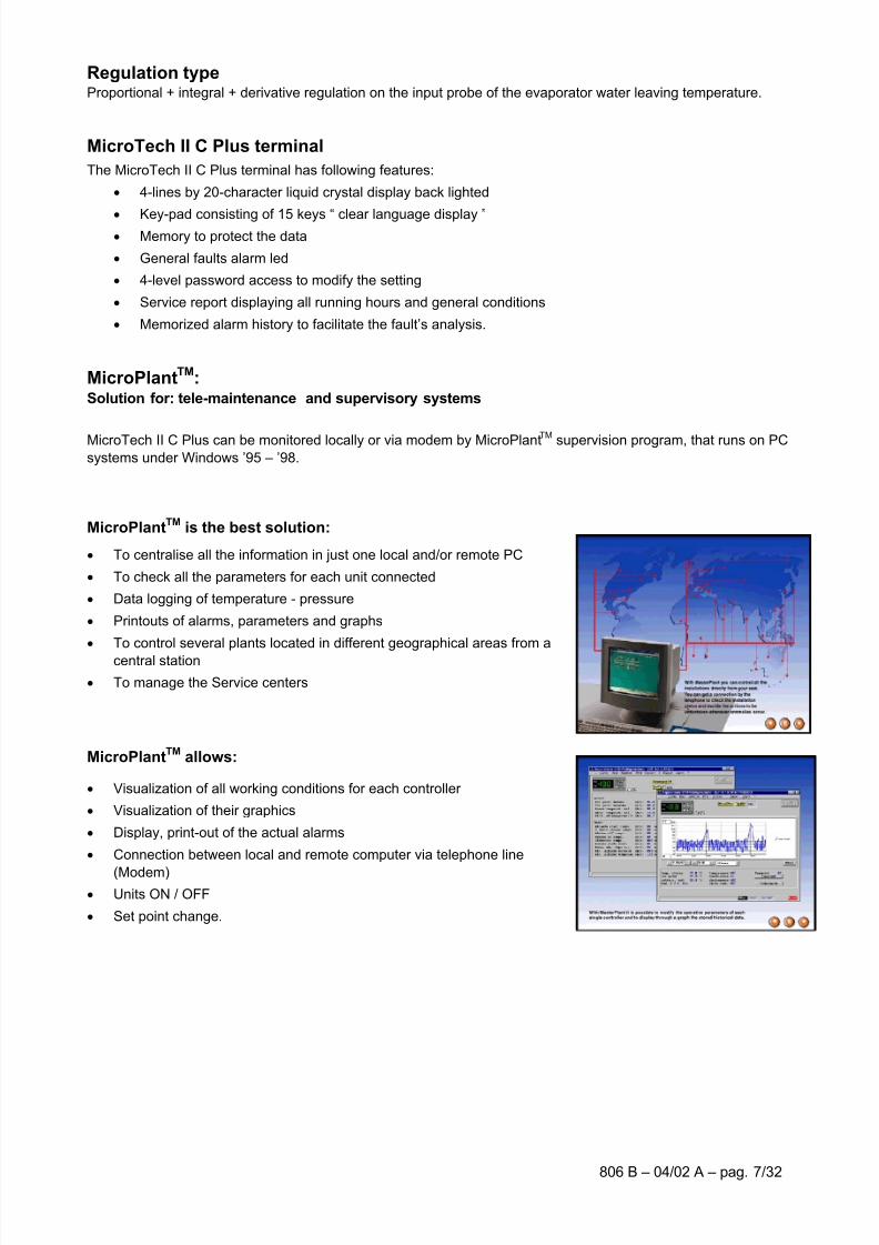
MicroPlantTM
:Solution for: tele-maintenance and supervisory systems
MicroTech II C Plus can be monitored locally or via modem by MicroPlantTM supervision program, that runs on PCsystems under Windows ’95 – ’98.
MicroPlantTM is the best solution:
• To centralise all the information in just one local and/or remote PC
• To check all the parameters for each unit connected
• Data logging of temperature - pressure
• Printouts of alarms, parameters and graphs
• To control several plants located in different geographical areas from a
central station
• To manage the Service centers
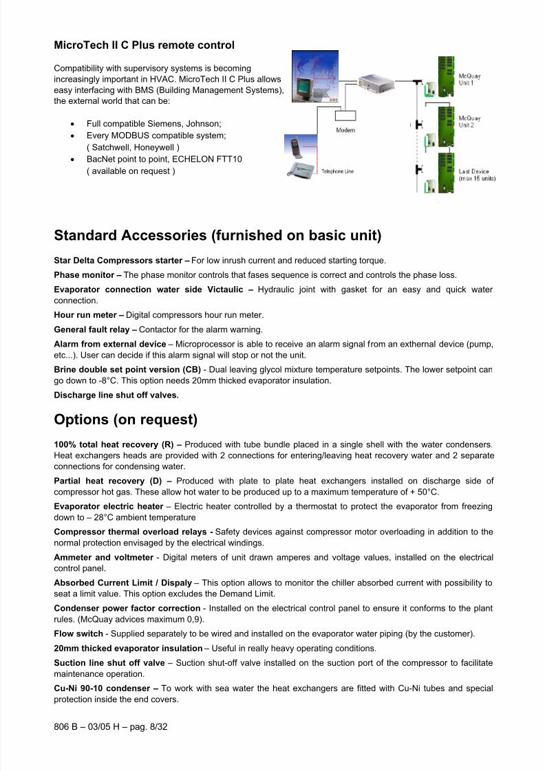
MicroPlantTM
allows:
• Visualization of all working conditions for each controller
• Visualization of their graphics
• Display, print-out of the actual alarms
• Connection between local and remote computer via telephone line
(Modem)• Units ON / OFF
• Set point change.
7/30/2019 McI Ecoplus Tm
http://slidepdf.com/reader/full/mci-ecoplus-tm 8/32
806 B – 03/05 H – pag. 8/32
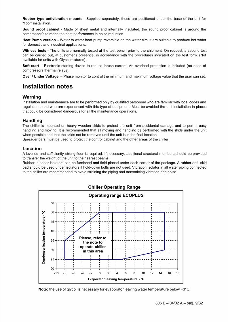
MicroTech II C Plus remote control
Compatibility with supervisory systems is becoming
increasingly important in HVAC. MicroTech II C Plus allows
easy interfacing with BMS (Building Management Systems),
the external world that can be:
• Full compatible Siemens, Johnson;
• Every MODBUS compatible system;( Satchwell, Honeywell )
• BacNet point to point, ECHELON FTT10
( available on request )
Standard Accessories (furnished on basic unit)
Star Delta Compressors starter – For low inrush current and reduced starting torque.
Phase monitor – The phase monitor controls that fases sequence is correct and controls the phase loss.
Evaporator connection water side Victaulic – Hydraulic joint with gasket for an easy and quick water
connection.
Hour run meter – Digital compressors hour run meter.
General fault relay – Contactor for the alarm warning.
Alarm from external device – Microprocessor is able to receive an alarm signal from an exthernal device (pump,
etc...). User can decide if this alarm signal will stop or not the unit.
Brine double set point version (CB) - Dual leaving glycol mixture temperature setpoints. The lower setpoint can
go down to -8°C. This option needs 20mm thicked evaporator insulation.
Discharge line shut off valves.
Options (on request)
100% total heat recovery (R) – Produced with tube bundle placed in a single shell with the water condensers.
Heat exchangers heads are provided with 2 connections for entering/leaving heat recovery water and 2 separate
connections for condensing water.
Partial heat recovery (D) – Produced with plate to plate heat exchangers installed on discharge side of
compressor hot gas. These allow hot water to be produced up to a maximum temperature of + 50°C.
Evaporator electric heater – Electric heater controlled by a thermostat to protect the evaporator from freezing
down to – 28°C ambient temperature
Compressor thermal overload relays - Safety devices against compressor motor overloading in addition to the
normal protection envisaged by the electrical windings.
Ammeter and voltmeter - Digital meters of unit drawn amperes and voltage values, installed on the electrical
control panel.
Absorbed Current Limit / Dispaly – This option allows to monitor the chiller absorbed current with possibility to
seat a limit value. This option excludes the Demand Limit.
Condenser power factor correction - Installed on the electrical control panel to ensure it conforms to the plant
rules. (McQuay advices maximum 0,9).
Flow switch - Supplied separately to be wired and installed on the evaporator water piping (by the customer).
20mm thicked evaporator insulation – Useful in really heavy operating conditions.
Suction line shut off valve – Suction shut-off valve installed on the suction port of the compressor to facilitate
maintenance operation.Cu-Ni 90-10 condenser – To work with sea water the heat exchangers are fitted with Cu-Ni tubes and special
protection inside the end covers.
7/30/2019 McI Ecoplus Tm
http://slidepdf.com/reader/full/mci-ecoplus-tm 9/32
806 B – 04/02 A – pag. 9/32
Rubber type antivibration mounts - Supplied separately, these are positioned under the base of the unit for
“floor” installation.
Sound proof cabinet - Made of sheet metal and internally insulated, the sound proof cabinet is around the
compressor/s to reach the best performance in noise reduction.
Heat Pump version – Water to water heat pump reversible on the water circuit are suitable to produce hot water
for domestic and industrial applications.
Witness tests - The units are normally tested at the test bench prior to the shipment. On request, a second test
can be carried out, at customer’s presence, in accordance with the procedures indicated on the test form. (Notavailable for units with Glycol mixtures).
Soft start – Electronic starting device to reduce inrush current. An overload protection is included (no need of
compressors thermal relays).
Over / Under Voltage – Phase monitor to control the minimum and maximum voltage value that the user can set.
Installation notes
WarningInstallation and maintenance are to be performed only by qualified personnel who are familiar with local codes and
regulations, and who are experienced with this type of equipment. Must be avoided the unit installation in places
that could be considered dangerous for all the maintenance operations.
HandlingThe chiller is mounted on heavy wooden skids to protect the unit from accidental damage and to permit easy
handling and moving. It is recommended that all moving and handling be performed with the skids under the unit
when possible and that the skids not be removed until the unit is in the final location.
Spreader bars must be used to protect the control cabinet and the other areas of the chiller.
Location A levelled and sufficiently strong floor is required. If necessary, additional structural members should be provided
to transfer the weight of the unit to the nearest beams.
Rubber-in-shear isolators can be furnished and field placed under each corner of the package. A rubber anti–skid
pad should be used under isolators if hold-down bolts are not used. Vibration isolator in all water piping connectedto the chiller are recommended to avoid straining the piping and transmitting vibration and noise.
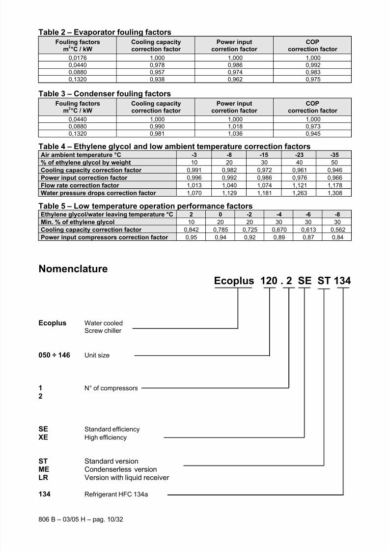
Chiller Operating Range
Note: the use of glycol is necessary for evaporator leaving water temperature below +3°C
Operating range ECOPLUS
20
25
30
35
40
45
50
55
-10 -8 -6 -4 -2 0 2 4 6 8 10 12 14 16 18
Evaporator leaving tem perature - °C
C o n d e n s e r l e a v i n g t e m p e r a t u r e - ° C
Please, refer tothe note to
operate chiller in this area
7/30/2019 McI Ecoplus Tm
http://slidepdf.com/reader/full/mci-ecoplus-tm 10/32
806 B – 03/05 H – pag. 10/32
Table 2 – Evaporator fouling factors
Fouling factorsm
2°C / kW
Cooling capacitycorrection factor
Power inputcorretion factor
COPcorrection factor
0,0176 1,000 1,000 1,000
0,0440 0,978 0,986 0,992
0,0880 0,957 0,974 0,983
0,1320 0,938 0,962 0,975
Table 3 – Condenser fouling factorsFouling factors
m2°C / kW
Cooling capacitycorrection factor
Power inputcorretion factor
COPcorrection factor
0,0440 1,000 1,000 1,000
0,0880 0,990 1,018 0,973
0,1320 0,981 1,036 0,945
Table 4 – Ethylene glycol and low ambient temperature correction factorsAir ambient temperature °C -3 -8 -15 -23 -35
% of ethylene glycol by weight 10 20 30 40 50
Cooling capacity correction factor 0,991 0,982 0,972 0,961 0,946
Power input correction factor 0,996 0,992 0,986 0,976 0,966
Flow rate correction factor 1,013 1,040 1,074 1,121 1,178
Water pressure drops correction factor 1,070 1,129 1,181 1,263 1,308
Table 5 – Low temperature operation performance factorsEthylene glycol/water leaving temperature °C 2 0 -2 -4 -6 -8
Min. % of ethylene glycol 10 20 20 30 30 30
Cooling capacity correction factor 0,842 0,785 0,725 0,670 0,613 0,562
Power input compressors correction factor 0,95 0,94 0,92 0,89 0,87 0,84
NomenclatureEcoplus 120 . 2 SE ST 134
Ecoplus Water cooledScrew chiller
050 ÷ 146 Unit size
1 N° of compressors2
SE Standard efficiency
XE High efficiency
ST Standard version ME Condenserless version LR Version with liquid receiver
134 Refrigerant HFC 134a
7/30/2019 McI Ecoplus Tm
http://slidepdf.com/reader/full/mci-ecoplus-tm 11/32
806 B – 04/02 A – pag. 11/32
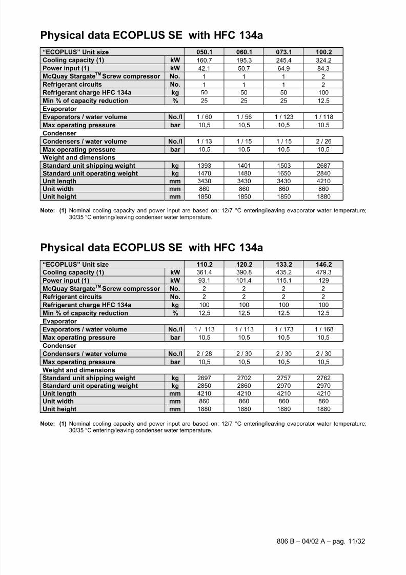
Physical data ECOPLUS SE with HFC 134a
“ECOPLUS” Unit size 050.1 060.1 073.1 100.2
Cooling capacity (1) kW 160.7 195.3 245.4 324.2
Power input (1) kW 42.1 50.7 64.9 84.3
McQuay StargateTM
Screw compressor No. 1 1 1 2
Refrigerant circuits No. 1 1 1 2
Refrigerant charge HFC 134a kg 50 50 50 100
Min % of capacity reduction % 25 25 25 12.5 Evaporator
Evaporators / water volume No./l 1 / 60 1 / 56 1 / 123 1 / 118
Max operating pressure bar 10,5 10,5 10,5 10.5
Condenser
Condensers / water volume No./l 1 / 13 1 / 15 1 / 15 2 / 26
Max operating pressure bar 10,5 10,5 10,5 10,5
Weight and dimensions
Standard unit shipping weight kg 1393 1401 1503 2687
Standard unit operating weight kg 1470 1480 1650 2840
Unit length mm 3430 3430 3430 4210
Unit width mm 860 860 860 860
Unit height mm 1850 1850 1850 1880
Note: (1) Nominal cooling capacity and power input are based on: 12/7 °C entering/leaving evaporator water temperature;30/35 °C entering/leaving condenser water temperature.
Physical data ECOPLUS SE with HFC 134a
“ECOPLUS” Unit size 110.2 120.2 133.2 146.2
Cooling capacity (1) kW 361.4 390.8 435.2 479.3
Power input (1) kW 93.1 101.4 115.1 129
McQuay StargateTM
Screw compressor No. 2 2 2 2
Refrigerant circuits No. 2 2 2 2
Refrigerant charge HFC 134a kg 100 100 100 100
Min % of capacity reduction % 12,5 12,5 12.5 12.5
Evaporator
Evaporators / water volume No./l 1 / 113 1 / 113 1 / 173 1 / 168
Max operating pressure bar 10,5 10,5 10,5 10,5
Condenser
Condensers / water volume No./l 2 / 28 2 / 30 2 / 30 2 / 30
Max operating pressure bar 10,5 10,5 10,5 10,5
Weight and dimensions
Standard unit shipping weight kg 2697 2702 2757 2762
Standard unit operating weight kg 2850 2860 2970 2970
Unit length mm 4210 4210 4210 4210
Unit width mm 860 860 860 860Unit height mm 1880 1880 1880 1880
Note: (1) Nominal cooling capacity and power input are based on: 12/7 °C entering/leaving evaporator water temperature;30/35 °C entering/leaving condenser water temperature.

7/30/2019 McI Ecoplus Tm
http://slidepdf.com/reader/full/mci-ecoplus-tm 12/32
806 B – 03/05 H – pag. 12/32
Physical data ECOPLUS XE with HFC 134a
“ECOPLUS” Unit size 050.1 060.1 073.1 100.2
Cooling capacity (1) kW 181 216.8 268.4 355.6
Power input (1) kW 39.7 48.1 59.3 79.3
McQuay StargateTM
Screw compressor No. 1 1 1 2
Refrigerant circuits No. 1 1 1 2
Refrigerant charge HFC 134a kg 50 50 50 100
Min % of capacity reduction % 25 25 25 12.5 Evaporator
Evaporators / water volume No./l 1 / 125 1 / 120 1 / 110 1 / 170
Max operating pressure bar 10,5 10,5 10,5 10.5
Condenser
Condensers / water volume No./l 1 / 22 1 / 25 1 / 25 2 / 44
Max operating pressure bar 10,5 10,5 10,5 10.5
Weight and dimensions
Standard unit shipping weight kg 1520 1530 1545 2800
Standard unit operating weight kg 1670 1675 1680 3015
Unit length mm 3430 3430 3430 4210
Unit width mm 860 860 860 860
Unit height mm 1850 1850 1850 1880
Note: (1) Nominal cooling capacity and power input are based on: 12/7 °C entering/leaving evaporator water temperature;30/35 °C entering/leaving condenser water temperature.
Physical data ECOPLUS XE with HFC 134a
“ECOPLUS” Unit size 110.2 120.2 133.2 146.2
Cooling capacity (1) kW 396.3 430.7 481.6 524.8
Power input (1) kW 87.2 95 104.8 114.4
McQuay StargateTM
Screw compressor No. 2 2 2 2
Refrigerant circuits No. 2 2 2 2
Refrigerant charge HFC 134a kg 100 100 100 100
Min % of capacity reduction % 12,5 12,5 12.5 12.5
Evaporator
Evaporators / water volume No./l 1 / 285 1 / 285 1 / 280 1 / 280
Max operating pressure bar 10,5 10,5 10,5 10,5
Condenser
Condensers / water volume No./l 2 / 47 2 / 50 2 / 59 2 / 68
Max operating pressure bar 10,5 10,5 10,5 10,5
Weight and dimensions
Standard unit shipping weight kg 2945 2955 2975 2990
Standard unit operating weight kg 3280 3290 3315 3340
Unit length mm 4210 4210 4210 4210
Unit width mm 860 860 860 860Unit height mm 1880 1880 1880 1880
Note: (1) Nominal cooling capacity and power input are based on: 12/7 °C entering/leaving evaporator water temperature;30/35 °C entering/leaving condenser water temperature.
7/30/2019 McI Ecoplus Tm
http://slidepdf.com/reader/full/mci-ecoplus-tm 13/32
806 B – 04/02 A – pag. 13/32
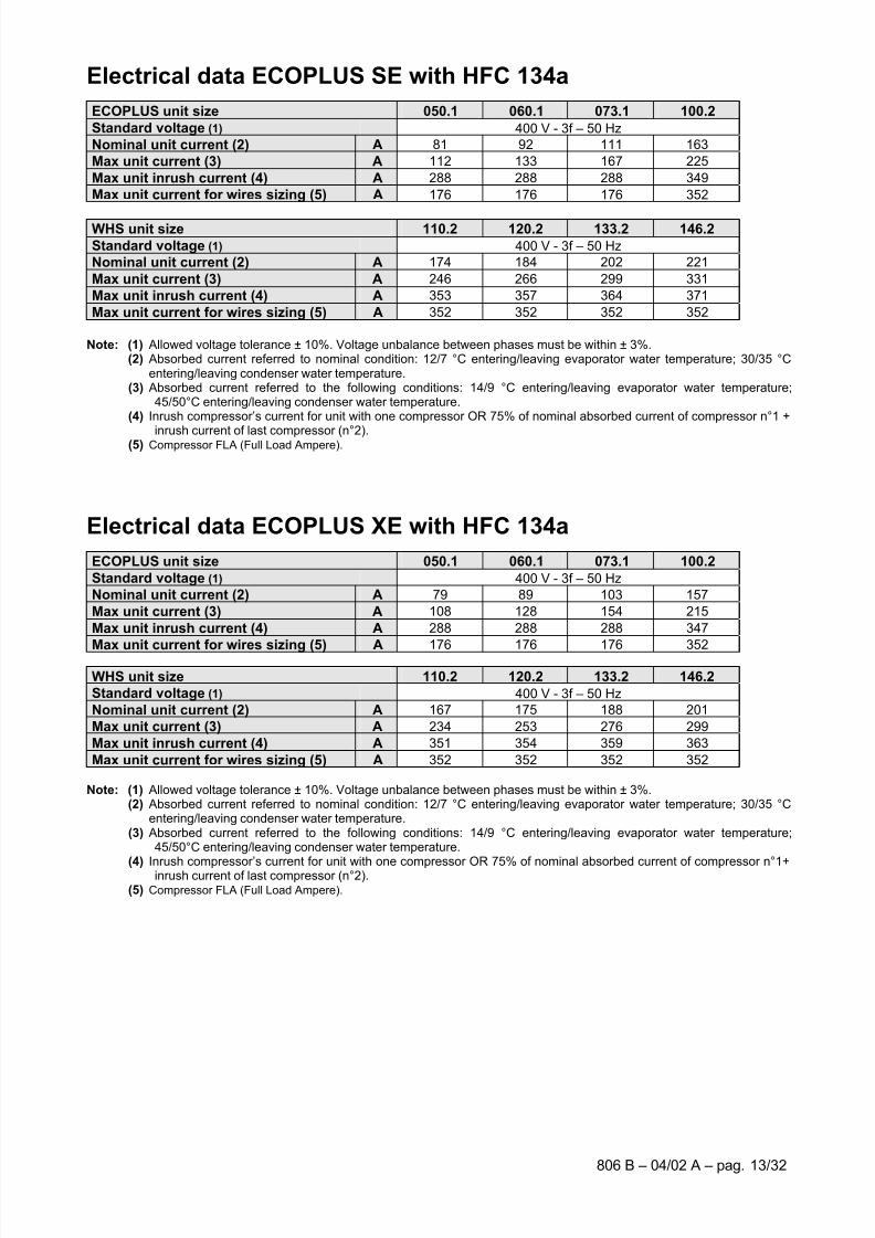
Electrical data ECOPLUS SE with HFC 134a
ECOPLUS unit size 050.1 060.1 073.1 100.2
Standard voltage (1) 400 V - 3f – 50 Hz
Nominal unit current (2) A 81 92 111 163
Max unit current (3) A 112 133 167 225
Max unit inrush current (4) A 288 288 288 349
Max unit current for wires sizing (5) A 176 176 176 352
WHS unit size 110.2 120.2 133.2 146.2
Standard voltage (1) 400 V - 3f – 50 Hz
Nominal unit current (2) A 174 184 202 221
Max unit current (3) A 246 266 299 331
Max unit inrush current (4) A 353 357 364 371
Max unit current for wires sizing (5) A 352 352 352 352
Note: (1) Allowed voltage tolerance ± 10%. Voltage unbalance between phases must be within ± 3%. (2) Absorbed current referred to nominal condition: 12/7 °C entering/leaving evaporator water temperature; 30/35 °C
entering/leaving condenser water temperature.(3) Absorbed current referred to the following conditions: 14/9 °C entering/leaving evaporator water temperature;
45/50°C entering/leaving condenser water temperature.(4) Inrush compressor’s current for unit with one compressor OR 75% of nominal absorbed current of compressor n°1 +
inrush current of last compressor (n°2).(5) Compressor FLA (Full Load Ampere).
Electrical data ECOPLUS XE with HFC 134a
ECOPLUS unit size 050.1 060.1 073.1 100.2
Standard voltage (1) 400 V - 3f – 50 Hz
Nominal unit current (2) A 79 89 103 157
Max unit current (3) A 108 128 154 215
Max unit inrush current (4) A 288 288 288 347
Max unit current for wires sizing (5) A 176 176 176 352
WHS unit size 110.2 120.2 133.2 146.2
Standard voltage (1) 400 V - 3f – 50 Hz
Nominal unit current (2) A 167 175 188 201
Max unit current (3) A 234 253 276 299
Max unit inrush current (4) A 351 354 359 363
Max unit current for wires sizing (5) A 352 352 352 352
Note: (1) Allowed voltage tolerance ± 10%. Voltage unbalance between phases must be within ± 3%. (2) Absorbed current referred to nominal condition: 12/7 °C entering/leaving evaporator water temperature; 30/35 °C
entering/leaving condenser water temperature.(3) Absorbed current referred to the following conditions: 14/9 °C entering/leaving evaporator water temperature;
45/50°C entering/leaving condenser water temperature.
(4) Inrush compressor’s current for unit with one compressor OR 75% of nominal absorbed current of compressor n°1+inrush current of last compressor (n°2).(5) Compressor FLA (Full Load Ampere).
7/30/2019 McI Ecoplus Tm
http://slidepdf.com/reader/full/mci-ecoplus-tm 14/32
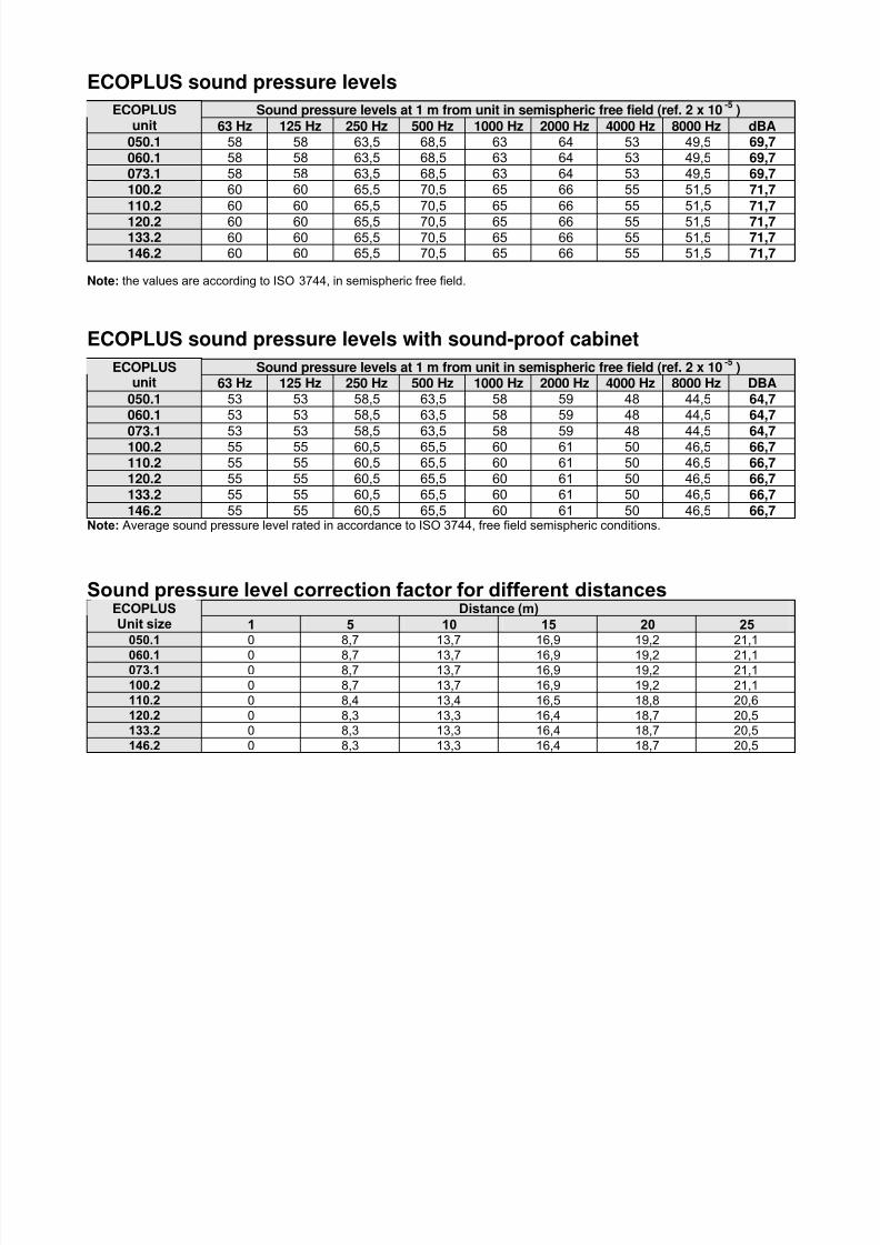
ECOPLUS sound pressure levels
Sound pressure levels at 1 m from unit in semispheric free field (ref. 2 x 10⁻⁵
)ECOPLUSunit 63 Hz 125 Hz 250 Hz 500 Hz 1000 Hz 2000 Hz 4000 Hz 8000 Hz dBA
050.1 58 58 63,5 68,5 63 64 53 49,5 69,7060.1 58 58 63,5 68,5 63 64 53 49,5 69,7073.1 58 58 63,5 68,5 63 64 53 49,5 69,7100.2 60 60 65,5 70,5 65 66 55 51,5 71,7
110.2 60 60 65,5 70,5 65 66 55 51,5 71,7
120.2 60 60 65,5 70,5 65 66 55 51,5 71,7133.2 60 60 65,5 70,5 65 66 55 51,5 71,7146.2 60 60 65,5 70,5 65 66 55 51,5 71,7
Note: the values are according to ISO 3744, in semispheric free field.
ECOPLUS sound pressure levels with sound-proof cabinet
Sound pressure levels at 1 m from unit in semispheric free field (ref. 2 x 10⁻⁵
)ECOPLUSunit 63 Hz 125 Hz 250 Hz 500 Hz 1000 Hz 2000 Hz 4000 Hz 8000 Hz DBA
050.1 53 53 58,5 63,5 58 59 48 44,5 64,7060.1 53 53 58,5 63,5 58 59 48 44,5 64,7
073.1 53 53 58,5 63,5 58 59 48 44,5 64,7100.2 55 55 60,5 65,5 60 61 50 46,5 66,7110.2 55 55 60,5 65,5 60 61 50 46,5 66,7120.2 55 55 60,5 65,5 60 61 50 46,5 66,7133.2 55 55 60,5 65,5 60 61 50 46,5 66,7146.2 55 55 60,5 65,5 60 61 50 46,5 66,7
Note: Average sound pressure level rated in accordance to ISO 3744, free field semispheric conditions.
Sound pressure level correction factor for different distancesDistance (m)ECOPLUS
Unit size 1 5 10 15 20 25050.1 0 8,7 13,7 16,9 19,2 21,1
060.1 0 8,7 13,7 16,9 19,2 21,1073.1 0 8,7 13,7 16,9 19,2 21,1
100.2 0 8,7 13,7 16,9 19,2 21,1
110.2 0 8,4 13,4 16,5 18,8 20,6
120.2 0 8,3 13,3 16,4 18,7 20,5
133.2 0 8,3 13,3 16,4 18,7 20,5
146.2 0 8,3 13,3 16,4 18,7 20,5
7/30/2019 McI Ecoplus Tm
http://slidepdf.com/reader/full/mci-ecoplus-tm 15/32
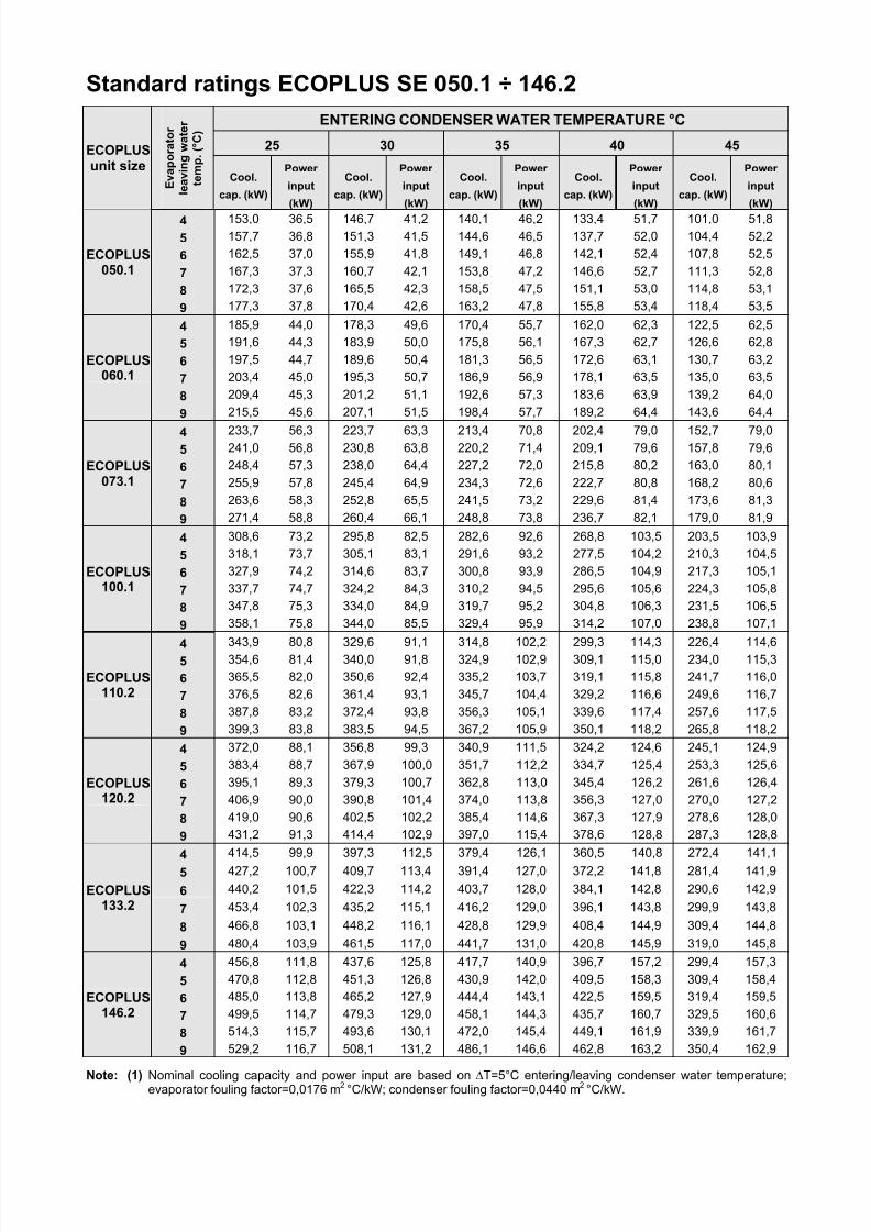
Standard ratings ECOPLUS SE 050.1 ÷ 146.2
ENTERING CONDENSER WATER TEMPERATURE °C
25 30 35 40 45ECOPLUS unit size
E v a p o r a t o r
l e a v i n g w a t e r
t e m p . ( ° C )
Cool.
cap. (kW)
Power
input
(kW)
Cool.
cap. (kW)
Power
input
(kW)
Cool.
cap. (kW)
Power
input
(kW)
Cool.
cap. (kW)
Power
input
(kW)
Cool.
cap. (kW)
Power
input
(kW)
4 153,0 36,5 146,7 41,2 140,1 46,2 133,4 51,7 101,0 51,8
5 157,7 36,8 151,3 41,5 144,6 46,5 137,7 52,0 104,4 52,2
6 162,5 37,0 155,9 41,8 149,1 46,8 142,1 52,4 107,8 52,5
7 167,3 37,3 160,7 42,1 153,8 47,2 146,6 52,7 111,3 52,8
8 172,3 37,6 165,5 42,3 158,5 47,5 151,1 53,0 114,8 53,1
ECOPLUS050.1
9 177,3 37,8 170,4 42,6 163,2 47,8 155,8 53,4 118,4 53,5
4 185,9 44,0 178,3 49,6 170,4 55,7 162,0 62,3 122,5 62,5
5 191,6 44,3 183,9 50,0 175,8 56,1 167,3 62,7 126,6 62,8
6 197,5 44,7 189,6 50,4 181,3 56,5 172,6 63,1 130,7 63,2
7 203,4 45,0 195,3 50,7 186,9 56,9 178,1 63,5 135,0 63,5
8 209,4 45,3 201,2 51,1 192,6 57,3 183,6 63,9 139,2 64,0
ECOPLUS060.1
9 215,5 45,6 207,1 51,5 198,4 57,7 189,2 64,4 143,6 64,4
4 233,7 56,3 223,7 63,3 213,4 70,8 202,4 79,0 152,7 79,05 241,0 56,8 230,8 63,8 220,2 71,4 209,1 79,6 157,8 79,6
6 248,4 57,3 238,0 64,4 227,2 72,0 215,8 80,2 163,0 80,1
7 255,9 57,8 245,4 64,9 234,3 72,6 222,7 80,8 168,2 80,6
8 263,6 58,3 252,8 65,5 241,5 73,2 229,6 81,4 173,6 81,3
ECOPLUS073.1
9 271,4 58,8 260,4 66,1 248,8 73,8 236,7 82,1 179,0 81,9
4 308,6 73,2 295,8 82,5 282,6 92,6 268,8 103,5 203,5 103,9
5 318,1 73,7 305,1 83,1 291,6 93,2 277,5 104,2 210,3 104,5
6 327,9 74,2 314,6 83,7 300,8 93,9 286,5 104,9 217,3 105,1
7 337,7 74,7 324,2 84,3 310,2 94,5 295,6 105,6 224,3 105,8
8 347,8 75,3 334,0 84,9 319,7 95,2 304,8 106,3 231,5 106,5
ECOPLUS100.1
9 358,1 75,8 344,0 85,5 329,4 95,9 314,2 107,0 238,8 107,1
4 343,9 80,8 329,6 91,1 314,8 102,2 299,3 114,3 226,4 114,65 354,6 81,4 340,0 91,8 324,9 102,9 309,1 115,0 234,0 115,3
6 365,5 82,0 350,6 92,4 335,2 103,7 319,1 115,8 241,7 116,0
7 376,5 82,6 361,4 93,1 345,7 104,4 329,2 116,6 249,6 116,7
8 387,8 83,2 372,4 93,8 356,3 105,1 339,6 117,4 257,6 117,5
ECOPLUS110.2
9 399,3 83,8 383,5 94,5 367,2 105,9 350,1 118,2 265,8 118,2
4 372,0 88,1 356,8 99,3 340,9 111,5 324,2 124,6 245,1 124,9
5 383,4 88,7 367,9 100,0 351,7 112,2 334,7 125,4 253,3 125,6
6 395,1 89,3 379,3 100,7 362,8 113,0 345,4 126,2 261,6 126,4
7 406,9 90,0 390,8 101,4 374,0 113,8 356,3 127,0 270,0 127,2
8 419,0 90,6 402,5 102,2 385,4 114,6 367,3 127,9 278,6 128,0
ECOPLUS120.2
9 431,2 91,3 414,4 102,9 397,0 115,4 378,6 128,8 287,3 128,8
4 414,5 99,9 397,3 112,5 379,4 126,1 360,5 140,8 272,4 141,1
5 427,2 100,7 409,7 113,4 391,4 127,0 372,2 141,8 281,4 141,9
6 440,2 101,5 422,3 114,2 403,7 128,0 384,1 142,8 290,6 142,9
7 453,4 102,3 435,2 115,1 416,2 129,0 396,1 143,8 299,9 143,8
8 466,8 103,1 448,2 116,1 428,8 129,9 408,4 144,9 309,4 144,8
ECOPLUS133.2
9 480,4 103,9 461,5 117,0 441,7 131,0 420,8 145,9 319,0 145,8
4 456,8 111,8 437,6 125,8 417,7 140,9 396,7 157,2 299,4 157,3
5 470,8 112,8 451,3 126,8 430,9 142,0 409,5 158,3 309,4 158,4
6 485,0 113,8 465,2 127,9 444,4 143,1 422,5 159,5 319,4 159,5
7 499,5 114,7 479,3 129,0 458,1 144,3 435,7 160,7 329,5 160,6
8 514,3 115,7 493,6 130,1 472,0 145,4 449,1 161,9 339,9 161,7
ECOPLUS146.2
9 529,2 116,7 508,1 131,2 486,1 146,6 462,8 163,2 350,4 162,9
Note: (1) Nominal cooling capacity and power input are based on∆
T=5°C entering/leaving condenser water temperature;evaporator fouling factor=0,0176 m2 °C/kW; condenser fouling factor=0,0440 m2 °C/kW.

7/30/2019 McI Ecoplus Tm
http://slidepdf.com/reader/full/mci-ecoplus-tm 16/32
806 B – 03/05 H – pag. 16/32
Standard ratings ECOPLUS XE 050.1 ÷ 146.2
ENTERING CONDENSER WATER TEMPERATURE °C
25 30 35 40 45ECOPLUS unit size
E v a p o r a t o r
l e a v i n g w a t e r
t e m p . ( ° C )
Cool.
cap. (kW)
Power
input
(kW)
Cool.
cap. (kW)
Power
input
(kW)
Cool.
cap. (kW)
Power
input
(kW)
Cool.
cap. (kW)
Power
input
(kW)
Cool.
cap. (kW)
Power
input
(kW)
4 171,2 34,6 163,9 39,1 156,4 44,0 148,6 49,3 140,6 55,0
5 176,9 34,7 169,5 39,3 161,8 44,3 153,8 49,6 145,6 55,3
6 182,8 34,9 175,2 39,5 167,3 44,5 159,2 49,8 150,8 55,5
7 188,8 35,0 181,0 39,7 173,0 44,7 164,7 50,1 156,1 55,8
8 195,0 35,2 187,0 39,9 178,7 45,0 170,3 50,4 161,5 56,1
ECOPLUS050.1
9 201,2 35,3 193,1 40,1 184,6 45,2 176,0 50,6 167,0 56,4
4 205,2 41,9 196,6 47,3 187,7 53,2 178,4 59,6 168,6 66,5
5 212,0 42,1 203,2 47,6 194,1 53,5 184,6 59,9 174,6 66,8
6 219,0 42,3 210,0 47,9 200,7 53,8 190,9 60,3 180,8 67,1
7 226,1 42,5 216,8 48,1 207,3 54,1 197,4 60,6 187,0 67,5
8 233,3 42,7 223,9 48,4 214,1 54,5 204,0 60,9 193,4 67,8
ECOPLUS060.1
9 240,6 42,9 231,0 48,7 221,0 54,8 210,7 61,3 199,9 68,2
4 254,0 51,6 243,3 58,3 232,2 65,5 220,7 73,2 208,5 81,65 262,5 51,9 251,5 58,6 240,2 65,9 228,4 73,7 216,0 82,0
6 271,1 52,2 259,9 59,0 248,3 66,3 236,2 74,1 223,5 82,5
7 279,9 52,5 268,4 59,3 256,6 66,7 244,2 74,5 231,2 82,9
8 288,8 52,8 277,1 59,7 265,0 67,1 252,4 75,0 239,1 83,4
ECOPLUS073.1
9 298,0 53,0 286,0 60,1 273,6 67,5 260,7 75,4 247,1 83,9
4 336,5 68,9 322,4 78,1 307,8 87,8 292,7 98,4 277,1 109,8
5 347,6 69,3 333,2 78,5 318,3 88,3 302,9 98,9 287,0 110,3
6 359,0 69,6 344,3 78,9 329,0 88,8 313,3 99,4 297,0 110,8
7 370,6 69,9 355,6 79,3 340,0 89,2 323,9 99,9 307,3 111,4
8 382,5 70,2 367,1 79,7 351,2 89,7 334,7 100,4 317,8 112,0
ECOPLUS100.1
9 394,6 70,5 378,8 80,0 362,6 90,2 345,8 101,0 328,5 112,5
4 374,9 75,9 359,2 85,9 343,0 96,7 326,1 108,3 308,5 120,85 387,4 76,2 371,3 86,4 354,7 97,2 337,5 108,8 319,5 121,4
6 400,2 76,6 383,7 86,8 366,7 97,7 349,1 109,4 330,7 122,0
7 413,1 76,9 396,3 87,2 378,9 98,2 360,9 110,0 342,2 122,6
8 426,4 77,3 409,2 87,7 391,4 98,7 373,1 110,6 353,9 123,2
ECOPLUS110.2
9 439,9 77,6 422,3 88,1 404,2 99,3 385,4 111,2 365,9 123,8
4 407,7 82,7 390,8 93,6 373,3 105,3 355,1 118,0 335,9 131,6
5 421,1 83,1 403,8 94,1 386,0 105,9 367,4 118,6 347,8 132,2
6 434,8 83,4 417,1 94,5 398,9 106,4 379,9 119,2 359,9 132,9
7 448,8 83,8 430,7 95,0 412,1 107,0 392,7 119,8 372,3 133,5
8 463,0 84,2 444,6 95,5 425,5 107,5 405,7 120,4 384,9 134,2
ECOPLUS120.2
9 477,6 84,6 458,7 96,0 439,2 108,1 419,0 121,0 397,8 134,9
4 455,7 91,2 436,9 103,3 417,5 116,2 397,3 130,2 376,0 145,2
5 470,7 91,6 451,5 103,8 431,7 116,8 411,0 130,8 389,3 145,9
6 486,1 92,1 466,4 104,3 446,1 117,4 425,0 131,5 402,9 146,6
7 501,7 92,5 481,6 104,8 460,9 118,0 439,3 132,2 416,7 147,3
8 517,6 92,9 497,1 105,3 475,9 118,6 453,9 132,8 430,8 148,0
ECOPLUS133.2
9 533,8 93,3 512,9 105,8 491,3 119,2 468,8 133,5 445,2 148,8
4 496,8 99,6 476,6 112,7 455,8 126,9 434,1 142,1 411,3 158,6
5 513,0 100,0 492,4 113,2 471,1 127,5 449,0 142,8 425,7 159,3
6 529,5 100,4 508,5 113,8 486,8 128,1 464,1 143,5 440,3 160,1
7 546,3 100,9 524,8 114,4 502,7 128,8 479,6 144,2 455,3 160,8
8 563,4 101,3 541,5 114,9 518,9 129,4 495,3 144,9 470,5 161,6
ECOPLUS146.2
9 580,9 101,7 558,6 115,4 535,5 130,1 511,4 145,7 486,0 162,4
Note: (1) Nominal cooling capacity and power input are based on ∆T=5°C entering/leaving condenser water temperature;evaporator fouling factor=0,0176 m2 °C/kW; condenser fouling factor=0,0440 m2 °C/kW.
7/30/2019 McI Ecoplus Tm
http://slidepdf.com/reader/full/mci-ecoplus-tm 17/32
806 B – 04/02 A – pag. 17/32
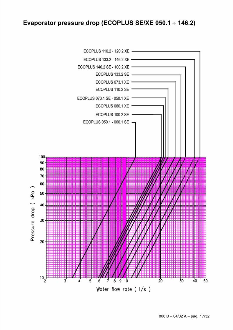
Evaporator pressure drop (ECOPLUS SE/XE 050.1 146.2)

7/30/2019 McI Ecoplus Tm
http://slidepdf.com/reader/full/mci-ecoplus-tm 18/32
806 B – 03/05 H – pag. 18/32
Condenser pressure drop (ECOPLUS SE/XE 050.1 146.2)
7/30/2019 McI Ecoplus Tm
http://slidepdf.com/reader/full/mci-ecoplus-tm 19/32
806 B – 04/02 A – pag. 19/32
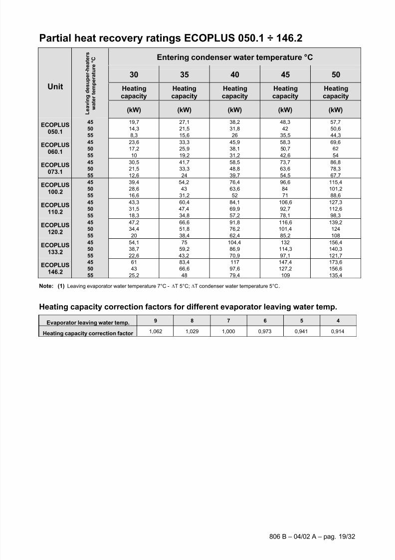
Partial heat recovery ratings ECOPLUS 050.1 ÷ 146.2
Entering condenser water temperature °C
30 35 40 45 50
Heating
capacity
Heating
capacity
Heating
capacity
Heating
capacity
Heating
capacity
Unit
L e a v i n g d e s u p e r - h e a t e r s
w a t e r
t e m p e r a t u r e ° C
(kW) (kW) (kW) (kW) (kW)
45 19,7 27,1 38,2 48,3 57,7
50 14,3 21,5 31,8 42 50,6ECOPLUS
050.155 8,3 15,6 26 35,5 44,3
45 23,6 33,3 45,9 58,3 69,6
50 17,2 25,9 38,1 50,7 62ECOPLUS
060.155 10 19,2 31,2 42,6 54
45 30,5 41,7 58,5 73,7 86,8
50 21,5 33,3 48,8 63,6 78,3ECOPLUS
073.155 12,6 24 39,7 54,5 67,7
45 39,4 54,2 76,4 96,6 115,4
50 28,6 43 63,6 84 101,2ECOPLUS
100.255 16,6 31,2 52 71 88,645 43,3 60,4 84,1 106,6 127,3
50 31,5 47,4 69,9 92,7 112,6ECOPLUS
110.255 18,3 34,8 57,2 78,1 98,3
45 47,2 66,6 91,8 116,6 139,2
50 34,4 51,8 76,2 101,4 124ECOPLUS
120.255 20 38,4 62,4 85,2 108
45 54,1 75 104,4 132 156,4
50 38,7 59,2 86,9 114,3 140,3ECOPLUS
133.255 22,6 43,2 70,9 97,1 121,7
45 61 83,4 117 147,4 173,6
50 43 66,6 97,6 127,2 156,6ECOPLUS
146.255 25,2 48 79,4 109 135,4
Note: (1) Leaving evaporator water temperature 7°C - ∆T 5°C; ∆T condenser water temperature 5°C.
Heating capacity correction factors for different evaporator leaving water temp.
Evaporator leaving water temp. 9 8 7 6 5 4
Heating capacity correction factor 1,062 1,029 1,000 0,973 0,941 0,914
7/30/2019 McI Ecoplus Tm
http://slidepdf.com/reader/full/mci-ecoplus-tm 20/32
806 B – 03/05 H – pag. 20/32
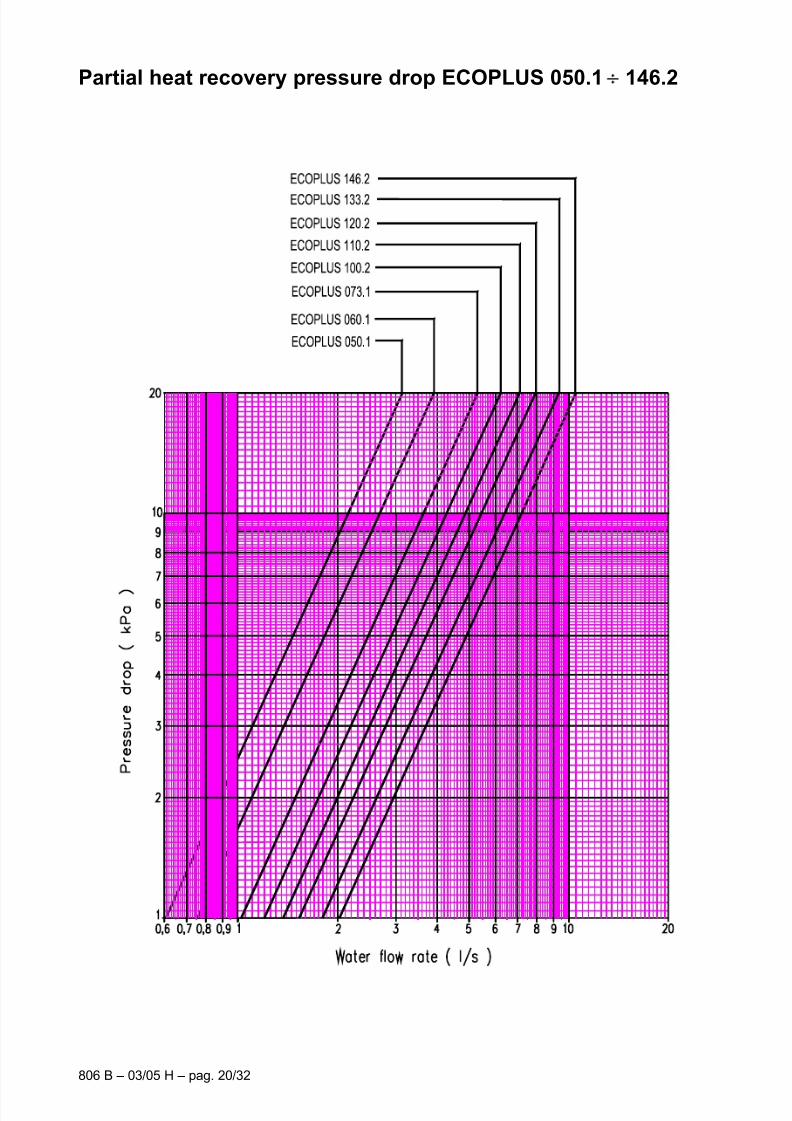
Partial heat recovery pressure drop ECOPLUS 050.1 146.2
7/30/2019 McI Ecoplus Tm
http://slidepdf.com/reader/full/mci-ecoplus-tm 21/32
806 B – 04/02 A – pag. 21/32
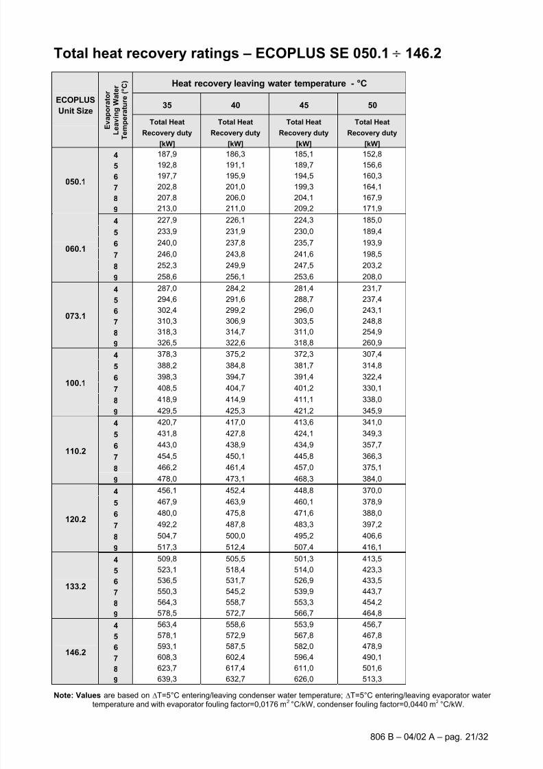
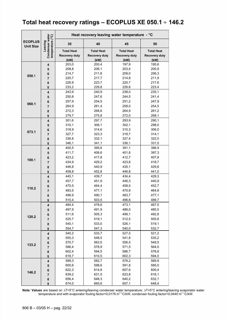
Total heat recovery ratings – ECOPLUS SE 050.1 146.2
Heat recovery leaving water temperature - °C
35 40 45 50ECOPLUS
Unit Size
E v a p o r a t o r
L
e a v i n g W a t e r
T e
m p e r a t u r e ( ° C )
Total Heat
Recovery duty[kW]
Total Heat
Recovery duty[kW]
Total Heat
Recovery duty[kW]
Total Heat
Recovery duty[kW]
4 187,9 186,3 185,1 152,8
5 192,8 191,1 189,7 156,6
6 197,7 195,9 194,5 160,3
7 202,8 201,0 199,3 164,1
8 207,8 206,0 204,1 167,9
050.1
9 213,0 211,0 209,2 171,9
4 227,9 226,1 224,3 185,0
5 233,9 231,9 230,0 189,4
6 240,0 237,8 235,7 193,9
7 246,0 243,8 241,6 198,5
8 252,3 249,9 247,5 203,2
060.1
9 258,6 256,1 253,6 208,0
4 287,0 284,2 281,4 231,7
5 294,6 291,6 288,7 237,4
6 302,4 299,2 296,0 243,1
7 310,3 306,9 303,5 248,8
8 318,3 314,7 311,0 254,9
073.1
9 326,5 322,6 318,8 260,9
4 378,3 375,2 372,3 307,4
5 388,2 384,8 381,7 314,8
6 398,3 394,7 391,4 322,4
7 408,5 404,7 401,2 330,1
8418,9 414,9 411,1 338,0
100.1
9 429,5 425,3 421,2 345,9
4 420,7 417,0 413,6 341,0
5 431,8 427,8 424,1 349,3
6 443,0 438,9 434,9 357,7
7 454,5 450,1 445,8 366,3
8 466,2 461,4 457,0 375,1
110.2
9 478,0 473,1 468,3 384,0
4 456,1 452,4 448,8 370,0
5 467,9 463,9 460,1 378,9
6 480,0 475,8 471,6 388,0
7 492,2 487,8 483,3 397,2
8 504,7 500,0 495,2 406,6
120.2
9 517,3 512,4 507,4 416,1
4 509,8 505,5 501,3 413,5
5 523,1 518,4 514,0 423,3
6 536,5 531,7 526,9 433,5
7 550,3 545,2 539,9 443,7
8 564,3 558,7 553,3 454,2
133.2
9 578,5 572,7 566,7 464,8
4 563,4 558,6 553,9 456,7
5 578,1 572,9 567,8 467,8
6 593,1 587,5 582,0 478,9
7 608,3 602,4 596,4 490,1
8 623,7 617,4 611,0 501,6
146.2
9 639,3 632,7 626,0 513,3
Note: Values are based on ∆T=5°C entering/leaving condenser water temperature; ∆T=5°C entering/leaving evaporator water temperature and with evaporator fouling factor=0,0176 m2 °C/kW, condenser fouling factor=0,0440 m2 °C/kW.
7/30/2019 McI Ecoplus Tm
http://slidepdf.com/reader/full/mci-ecoplus-tm 22/32
806 B – 03/05 H – pag. 22/32
Total heat recovery ratings – ECOPLUS XE 050.1 146.2
Heat recovery leaving water temperature - °C
35 40 45 50ECOPLUS
Unit Size
L e a v i n g
C o n d e n s e r w a t e r
t e
m p e r a t u r e ( ° C )
Total Heat
Recovery duty[kW]
Total Heat
Recovery duty[kW]
Total Heat
Recovery duty[kW]
Total Heat
Recovery duty[kW]
4 203,0 200,4 197,9 195,6
5 208,8 206,1 203,4 200,9
6 214,7 211,8 209,0 206,3
7 220,7 217,7 214,8 211,9
8 226,9 223,7 220,7 217,6
050.1
9 233,2 229,8 226,6 223,4
4 243,9 240,9 238,0 235,1
5 250,8 247,6 244,5 241,4
6 257,9 254,5 251,2 247,9
7 264,9 261,4 258,0 254,5
8 272,3 268,6 264,9 261,2
060.1
9 279,7 275,8 272,0 268,1
4 301,6 297,7 293,9 290,1
5 310,1 306,1 302,1 298,0
6 318,9 314,6 310,3 306,0
7 327,7 323,3 318,7 314,1
8 336,8 332,1 327,4 322,5
073.1
9 346,1 341,1 336,1 331,0
4 400,5 395,6 391,1 386,9
5 411,7 406,6 401,8 397,3
6 423,2 417,8 412,7 407,8
7 434,9 429,2 423,8 418,7
8446,8 440,9 435,1 429,8
100.1
9 458,8 452,8 446,8 441,0
4 445,1 439,7 434,4 429,3
5 457,7 451,9 446,3 440,9
6 470,5 464,4 458,5 452,7
7 483,5 477,1 470,9 464,8
8 496,9 490,1 483,7 477,1
110.2
9 510,4 503,5 496,6 489,7
4 484,4 478,6 473,1 467,5
5 497,9 491,9 486,0 480,0
6 511,6 505,3 499,1 492,8
7 525,7 519,1 512,5 505,8
8 540,1 533,0 526,1 519,1
120.2
9 554,7 547,3 540,0 532,7
4 540,2 533,7 527,5 521,2
5 555,3 548,5 541,8 535,2
6 570,7 563,5 556,5 549,5
7 586,4 578,9 571,5 564,0
8 602,4 594,5 586,7 578,8
133.2
9 618,7 610,5 602,3 594,0
4 589,3 582,7 576,2 569,9
5 605,6 598,6 591,8 585,0
6 622,3 614,9 607,6 600,4
7 639,2 631,5 623,8 616,1
8 656,4 648,3 640,2 632,1
146.2
9 674,0 665,6 657,1 648,4
Note: Values are based on ∆T=5°C entering/leaving condenser water temperature; ∆T=5°C entering/leaving evaporator water temperature and with evaporator fouling factor=0,0176 m2 °C/kW, condenser fouling factor=0,0440 m2 °C/kW.

7/30/2019 McI Ecoplus Tm
http://slidepdf.com/reader/full/mci-ecoplus-tm 23/32
806 B – 04/02 A – pag. 23/32
Total heat recovery exchangers pressure drop
(ECOPLUS SE/XE 050.1 146.2)

7/30/2019 McI Ecoplus Tm
http://slidepdf.com/reader/full/mci-ecoplus-tm 24/32
806 B – 03/05 H – pag. 24/32
D i m e n s i o n s E C O P L U S 0 5 0 . 1 ÷
0 7 3 . 1
3 4 3 0 m
m
1850 mm
8 6 0 m m
7/30/2019 McI Ecoplus Tm
http://slidepdf.com/reader/full/mci-ecoplus-tm 25/32
806 B – 04/02 A – pag. 25/32
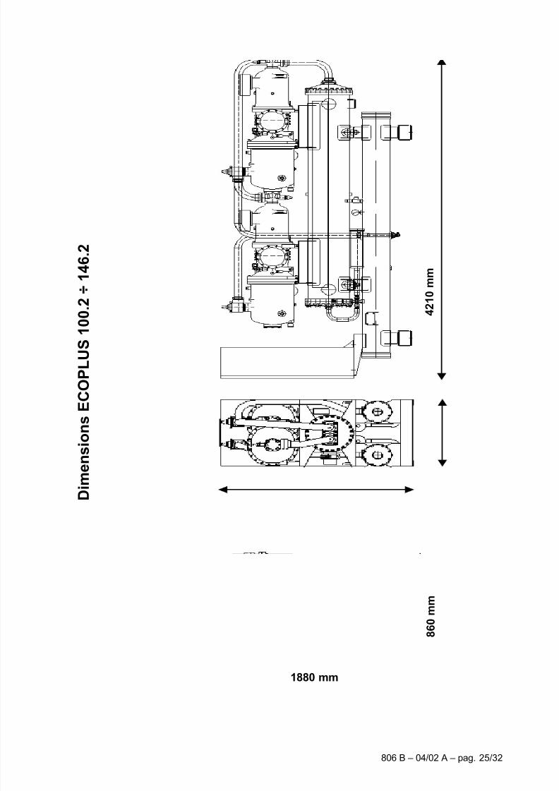
D i m e n s i o n s
E C O P L U S 1 0 0 . 2 ÷ 1
4 6 . 2
4 2 1 0 m m
1880 mm
8 6 0 m m
7/30/2019 McI Ecoplus Tm
http://slidepdf.com/reader/full/mci-ecoplus-tm 26/32
806 B – 03/05 H – pag. 26/32
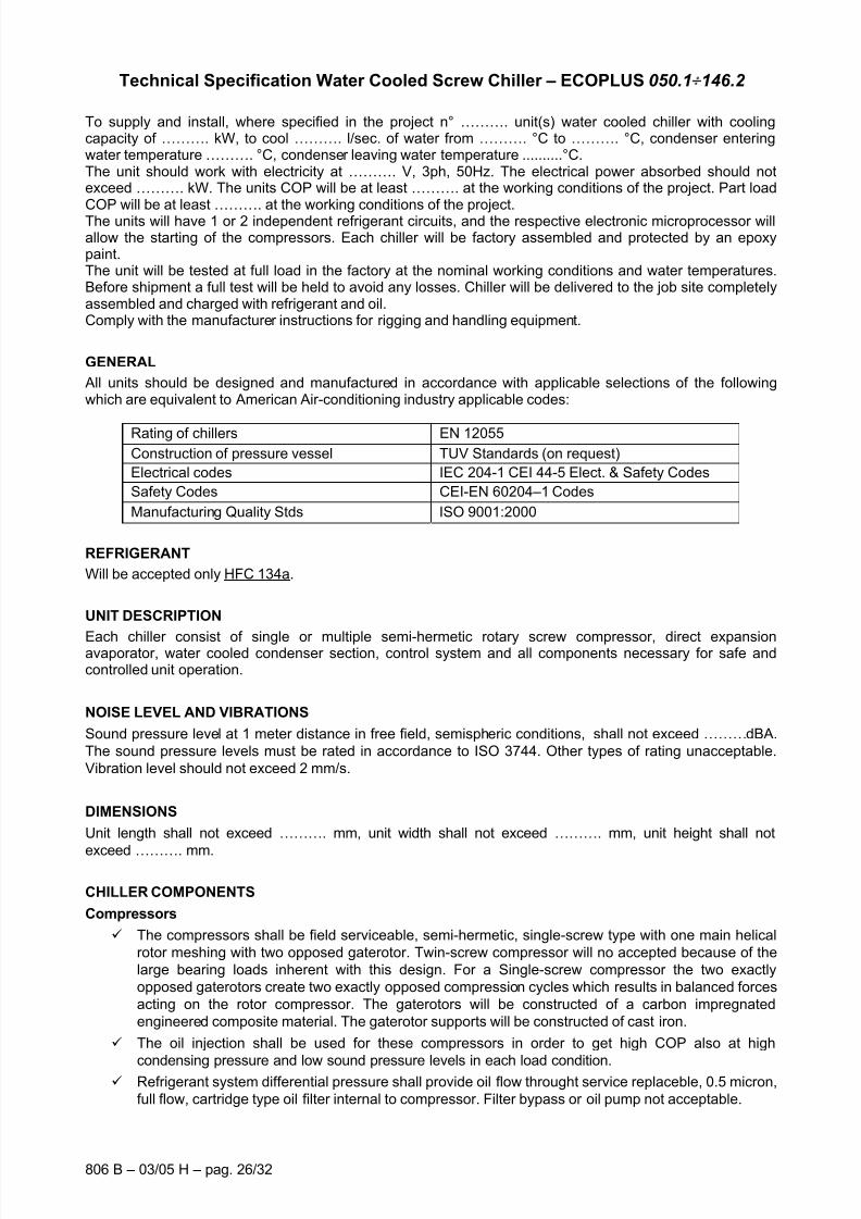
Technical Specification Water Cooled Screw Chiller – ECOPLUS 050.1 146.2
To supply and install, where specified in the project n° ………. unit(s) water cooled chiller with coolingcapacity of ………. kW, to cool ………. l/sec. of water from ………. °C to ………. °C, condenser enteringwater temperature ………. °C, condenser leaving water temperature ..........°C.The unit should work with electricity at ………. V, 3ph, 50Hz. The electrical power absorbed should notexceed ………. kW. The units COP will be at least ………. at the working conditions of the project. Part loadCOP will be at least ………. at the working conditions of the project.The units will have 1 or 2 independent refrigerant circuits, and the respective electronic microprocessor willallow the starting of the compressors. Each chiller will be factory assembled and protected by an epoxypaint.The unit will be tested at full load in the factory at the nominal working conditions and water temperatures.Before shipment a full test will be held to avoid any losses. Chiller will be delivered to the job site completelyassembled and charged with refrigerant and oil.Comply with the manufacturer instructions for rigging and handling equipment.
GENERAL
All units should be designed and manufactured in accordance with applicable selections of the followingwhich are equivalent to American Air-conditioning industry applicable codes:
Rating of chillers EN 12055
Construction of pressure vessel TUV Standards (on request)
Electrical codes IEC 204-1 CEI 44-5 Elect. & Safety Codes
Safety Codes CEI-EN 60204–1 Codes
Manufacturing Quality Stds ISO 9001:2000
REFRIGERANT
Will be accepted only HFC 134a.
UNIT DESCRIPTION
Each chiller consist of single or multiple semi-hermetic rotary screw compressor, direct expansionavaporator, water cooled condenser section, control system and all components necessary for safe andcontrolled unit operation.
NOISE LEVEL AND VIBRATIONS
Sound pressure level at 1 meter distance in free field, semispheric conditions, shall not exceed ………dBA.
The sound pressure levels must be rated in accordance to ISO 3744. Other types of rating unacceptable.
Vibration level should not exceed 2 mm/s.
DIMENSIONS
Unit length shall not exceed ………. mm, unit width shall not exceed ………. mm, unit height shall not
exceed ………. mm.
CHILLER COMPONENTS
Compressors
The compressors shall be field serviceable, semi-hermetic, single-screw type with one main helical
rotor meshing with two opposed gaterotor. Twin-screw compressor will no accepted because of the
large bearing loads inherent with this design. For a Single-screw compressor the two exactly
opposed gaterotors create two exactly opposed compression cycles which results in balanced forces
acting on the rotor compressor. The gaterotors will be constructed of a carbon impregnated
engineered composite material. The gaterotor supports will be constructed of cast iron.
The oil injection shall be used for these compressors in order to get high COP also at high
condensing pressure and low sound pressure levels in each load condition. Refrigerant system differential pressure shall provide oil flow throught service replaceble, 0.5 micron,
full flow, cartridge type oil filter internal to compressor. Filter bypass or oil pump not acceptable.
7/30/2019 McI Ecoplus Tm
http://slidepdf.com/reader/full/mci-ecoplus-tm 27/32
806 B – 04/02 A – pag. 27/32
The compressor’s oil cooling must be realized by liquid injection. External dedicated heat exchanger
and additional piping to carry the oil from the compressor to heat exchanger and viceversa will be
not accepted.
The compressor shall be provided with a integrated high efficiency, oil separator and with built-in oil
filter.
The compressor shall be direct electrical drive, without gear transmission between the screw and the
electrical motor. The motor’s compressor shall be designed for star/delta. Soft start should be
available as option. The compressor casing shall be provided with ports to realize economized refrigerant cycles.
Shall be present two thermal protection realized by a thermistor for high temperature protection to
motor and a thermistor for discharge gas high temperature protection.
The compressor shall be provided with an automatic spring return of capacity control valve to the
minimum load position to ensure compressor starting always at minimum motor load so with the
minimum mechanical stress.
Evaporator
The units shall be supplied with shell and tubes counter-flow evaporator single refrigerant pass. It will
be direct expansion with refrigerant inside the tubes and water outside (shell side) with carbon steel
tube sheets, with straight copper tubes that are spirally wound internally for higher efficiencies,expanded on the tube plates.
The external shell, shall be linked with an electrical heater to prevent freezing up to -28 C ambient
temperature, commanded by a thermostat and shall be insulated with flexible, closed cell
polyurethane insulation material.
The evaporator will have 1 or 2 circuits, one for each compressor and shall be single refrigerant pass
to ensure a simplier oil circulation so to ensure always a perfect oil return to the compressor.
Evaporator is manufactured in accordance to PED approval.
Condensers
Condensers will be shell and cleanable, through-tube type.
The unit will have one condensers per circuit.
Each condenser shall have a carbon steel and seamless, integrally finned high efficiency copper
tubes, roll expanded into heavy carbon steel tube sheets.
Water heads shall be removable and include vent and drain plugs.
Condensers will come complete with liquid shut-off valve, spring loaded relief valve.
Refrigerant circuit
The unit must have refrigerant circuits completely independent of each other with one compressor per circuit.
Each circuit shall include an: thermostatic expansion valve, compressor discharge shut-off valve, aliquid line shut-off valve with charging connection, replaceable core filter-drier, sight glass with
moisture indicator and insulated suction line. Suction line shut-off valve should be available asoption.
7/30/2019 McI Ecoplus Tm
http://slidepdf.com/reader/full/mci-ecoplus-tm 28/32
806 B – 03/05 H – pag. 28/32
Regulation of cooling capacity
Each unit will have a microprocessor for the control of compressor slide valve’s position (2 slidevalves, one for each compressor’s cycles).
The slides shall have a stepless motion that allows a unit’s operation with infinitely variable capacitycontrol down to 25% (1 compressor) or down to 12,5% (2 compressors) of the cooling capacity. Thechiller shall be capable of stable operation to a minimum of 25% (1 compressor) or to a minimum of 12,5% (2 compressors) of full load without hot gas bypass.
Step unloading unacceptable because of evaporator leaving water temperature fluctuation and lowcompressor’s efficiency at partial load.
The system shall stage the unit based on the leaving water temperature.
Control panel
Field power connections, control interlock terminals, and unit control system should be centrallylocated in an electric panel (IP 54).
The Power components and control equipment shall be separately mounted in differentcompartments of the control panel.
The Compressor starting method will be star/delta, with an option for Softstart.
Power and starting controls should include fuses and contactors for the compressor and fan motor windings.
Operating and safety controls should include energy saving; emergency stop switch; thermaloverload protection for each compressor motor; high and low pressure cut-out switch (for eachrefrigerant circuit); anti-freeze thermostat; cut-out switch for each compressor.
All of the information regarding the unit shall be shown on a display with a built-in calendar and clockthat will provide unit scheduling throughout the year.
The following features and functions shall be included:
- resetting chilled water temperature by controlling the return water temperature or by a remote 4-20 mA DC signal:
- soft load function to prevent the system from operating at full load during the chilled fluid pulldownperiod;
- password protection of critical parameters of control;- start-to-start and stop-to-start timers to provide minimum compressor off-time with maximum motor
protection;- communication capability with a PC or remote monitoring;- lead-lag selection by manual or automatically by circuit run hours;- double set point for brine unit version;- scheduling via internal time clock to allow programming of a yearly start-stop schedule
accommodating weekends and holidays.
7/30/2019 McI Ecoplus Tm
http://slidepdf.com/reader/full/mci-ecoplus-tm 29/32
806 B – 04/02 A – pag. 29/32
Display Capabilities
The controller as a minimum shall be capable of monitoring and displaying the following data: -
Operating Conditions Alarms
Ent./ Lvg. Evaporator fluid Temp. Phase Monitor
Ent.ering Condenser fluid Temp. Freeze Protection
Operating Chilled Fluid Setpoint Evaporator Flow
Oil / Discharge gas Press. (per comp.) Low Gas Pressure (per comp.)Condensing Press. (per comp.) Transition Fault, (per comp.)
Evaporator Press. (per comp.) Oil Diff. press. (per comp.)
Unit Enabled Low Oil Pressure (per comp.)
Compressor Enabled High Gas Pressure Trip (per comp.)
Water Setpoint Reset Motor Overload, (per comp.)
Demand Limit or Current Limit Transducer faults
(Site Selectable) Units Off-Line
External fault
Processor FaultsMaintenance requirements
Standard Customer Interfaces
`The controller as a minimum shall be capable of providing the following interlocks: -
Chiller Enable Signal: Digital Input,
customer contact must be capable of handling 24Volts, 50HZ, 1 Amp.
Chiller Common Fault: Volt free, normally open, digital contact,
Must be capable of switching 250 V, 50 HZ, 10 Amp.
Pump Enable Signal:: Volt free, normally open, digital contact,Must be capable of switching 250 V, 50 HZ, 10 Amp.
Setpoint Override:: 4 – 20 mA DC analoque input signal.
Demand Limit:: 4 – 20 mA DC analoque input signal.
Or
Current Limit:: 4 – 20 mA DC analoque input signal.
Optional Customer Interfaces
Compressor Running Signals: Volt free, normally open, digital contact,
Capable of switching 250 V, 50 HZ, 10 Amp.
Optional High Level Communications Interface
Using ModBus, Lonworks or Bacnet protocols
7/30/2019 McI Ecoplus Tm
http://slidepdf.com/reader/full/mci-ecoplus-tm 30/32
806 B – 03/05 H – pag. 30/32
NOTE ______________________________________________________ ______________________________________________________ ______________________________________________________ ______________________________________________________
______________________________________________________ ______________________________________________________ ______________________________________________________ ______________________________________________________ ______________________________________________________ ______________________________________________________ ______________________________________________________ ______________________________________________________
______________________________________________________ ______________________________________________________ ______________________________________________________ ______________________________________________________ ______________________________________________________ ______________________________________________________
______________________________________________________ ______________________________________________________
______________________________________________________ ______________________________________________________ ______________________________________________________ ______________________________________________________
______________________________________________________ ______________________________________________________ ______________________________________________________ ______________________________________________________ ______________________________________________________ ______________________________________________________
7/30/2019 McI Ecoplus Tm
http://slidepdf.com/reader/full/mci-ecoplus-tm 31/32
806 B – 04/02 A – pag. 31/32
NOTE
______________________________________________________ ______________________________________________________ ______________________________________________________ ______________________________________________________
______________________________________________________ ______________________________________________________ ______________________________________________________ ______________________________________________________ ______________________________________________________ ______________________________________________________ ______________________________________________________ ______________________________________________________
______________________________________________________ ______________________________________________________ ______________________________________________________ ______________________________________________________ ______________________________________________________ ______________________________________________________
______________________________________________________ ______________________________________________________
______________________________________________________ ______________________________________________________ ______________________________________________________ ______________________________________________________
______________________________________________________ ______________________________________________________ ______________________________________________________ ______________________________________________________ ______________________________________________________ ______________________________________________________

7/30/2019 McI Ecoplus Tm
http://slidepdf.com/reader/full/mci-ecoplus-tm 32/32
We reserve the right to make changes in design and construction at any time without notice, thus the cover picture is not binding.