Embed Size (px)
Citation preview

MC1000 Multi-Function
Calibrator

Table of Contents
1. Introduction1.1 Customer Service . . . . . . . . . . . . . . . .11.2 Standard Equipment . . . . . . . . . . . . . .11.3 Safety Information . . . . . . . . . . . . . . . .2
2. Quick Start InstructionsA. Key Functions . . . . . . . . . . . . . . . . . . . .6B. Setpoints . . . . . . . . . . . . . . . . . . . . . . .7
3. Connection Diagrams & InstructionsA. Measuring High Voltage AC or DC . . .10B. Measuring Low Voltage
and Frequency . . . . . . . . . . . . . . . . . .10C. Measuring Current . . . . . . . . . . . . . . .11D. Sourcing Current . . . . . . . . . . . . . . . .11E. Simulating Current . . . . . . . . . . . . . . .12F. Sourcing Voltage/
Resistance/Frequency . . . . . . . . . . . . .12G. Sourcing a Thermocouple Signal . . . .13H. Measuring Temperature Using a
Thermocouple . . . . . . . . . . . . . . . . . .13I. Measuring Resistance (RTDs) . . . . . . .13J. Sourcing Resistance (RTDs) . . . . . . . .15
4. Serial Communications . . . . . . . . . . . .155. Maintenance
A. Power Requirements . . . . . . . . . . . . .19B. Calibration . . . . . . . . . . . . . . . . . . . . .19C. Field Replacement Fuse . . . . . . . . . . .19
6. Specifications . . . . . . . . . . . . . . . . . . .207. Warranty . . . . . . . . . . . . . . . . . . . . . . .23
1
MC-1000
1. IntroductionThe MC1000 is designed to be a versatile, easyto use multi-function calibrator with a simpleuser interface. The following instructions willallow the user to begin simple calibration tasksby learning the basic operation of the keys andtheir functions.
1.1 Customer ServiceCorporate Office:
www.martelcorp.come-mail: [email protected]
Tel: (603) 434-1433 800-821-0023 Fax: (603) 434-1653
Martel Electronics3 Corporate Park Dr.
Derry, NH 03038
1.2 Standard EquipmentCheck to see if your calibrator is complete. It should include: MC1000 Calibrator, Instruction Manual, TestLeads, Rubber Boot and NIST Certificate.
2
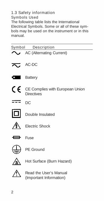
1.3 Safety information Symbols UsedThe following table lists the InternationalElectrical Symbols. Some or all of these sym-bols may be used on the instrument or in thismanual.
Symbol DescriptionAC (Alternating Current)
AC-DC
Battery
CE Complies with European UnionDirectives
DC
Double Insulated
Electric Shock
Fuse
PE Ground
Hot Surface (Burn Hazard)
Read the User’s Manual (Important Information)
3
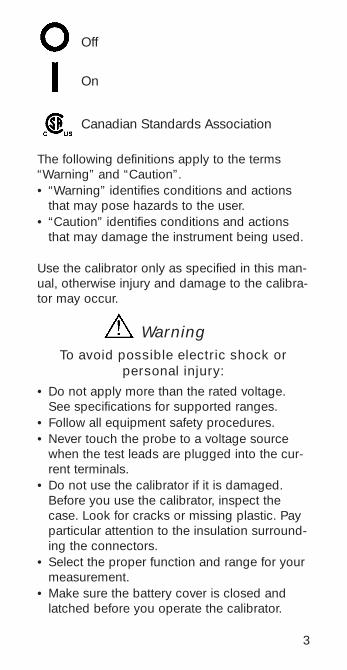
Off
On
Canadian Standards Association
The following definitions apply to the terms“Warning” and “Caution”.• “Warning” identifies conditions and actions
that may pose hazards to the user.• “Caution” identifies conditions and actions
that may damage the instrument being used.
Use the calibrator only as specified in this man-ual, otherwise injury and damage to the calibra-tor may occur.
WarningTo avoid possible electric shock or
personal injury:
• Do not apply more than the rated voltage.See specifications for supported ranges.
• Follow all equipment safety procedures.• Never touch the probe to a voltage source
when the test leads are plugged into the cur-rent terminals.
• Do not use the calibrator if it is damaged.Before you use the calibrator, inspect thecase. Look for cracks or missing plastic. Payparticular attention to the insulation surround-ing the connectors.
• Select the proper function and range for yourmeasurement.
• Make sure the battery cover is closed andlatched before you operate the calibrator.
4
• Remove test leads from the calibrator beforeyou open the battery door.
• Inspect the test leads for damaged insulationor exposed metal. Check test leads continuity.Replace damaged test leads before you usethe calibrator.
• When using the probes, keep your fingersaway from the probe contacts. Keep your fin-gers behind the finger guards on the probes.
• Connect the common test lead before youconnect the live test lead. When you discon-nect test leads, disconnect the live test leadfirst.
• Do not use the calibrator if it operates abnor-mally. Protection may be impaired. When indoubt, have the calibrator serviced.
• Do not operate the calibrator around explo-sive gas, vapor, or dust.
• When using a pressure module, make surethe process pressure line is shut off anddepressurized before you connect it or dis-connect it from the pressure module.
• Disconnect test leads before changing toanother measure or source function.
• When servicing the calibrator, use only speci-fied replacement parts.
• To avoid false readings, which could lead topossible electric shock or personal injury,replace the battery as soon as the batteryindicator appears.
• To avoid a violent release of pressure in apressurized system, shut off the valve andslowly bleed off the pressure before youattach the pressure module to the pressureline.
5
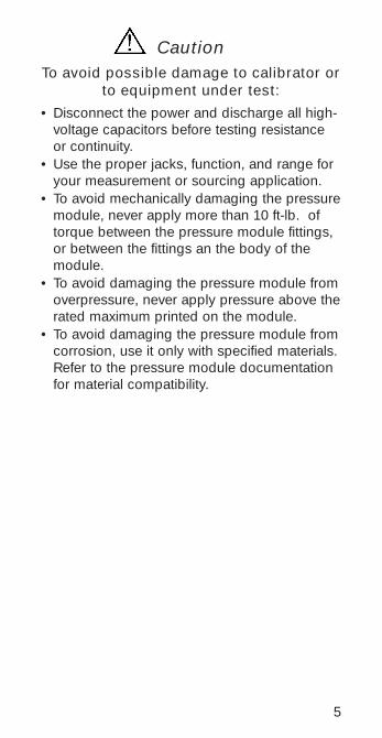
CautionTo avoid possible damage to calibrator or
to equipment under test:
• Disconnect the power and discharge all high-voltage capacitors before testing resistanceor continuity.
• Use the proper jacks, function, and range foryour measurement or sourcing application.
• To avoid mechanically damaging the pressuremodule, never apply more than 10 ft-lb. oftorque between the pressure module fittings,or between the fittings an the body of themodule.
• To avoid damaging the pressure module fromoverpressure, never apply pressure above therated maximum printed on the module.
• To avoid damaging the pressure module fromcorrosion, use it only with specified materials.Refer to the pressure module documentationfor material compatibility.

2. Quick Start Instructions
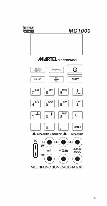
A. Key Functions
Key FunctionInput/Output Toggles the function selected
from measurement mode tosource mode.
V/mA/Hz Selects between volts, mil-liamps, and frequency modes
TC/RTD Selects between temperaturemodes either T/C or RTD.Ohms and mV ranges are alsoincluded in these functions.
Ranges/Units This key toggles through allthe ranges for a chosen func-tion. Example: If T/C mode isselected the Range key tog-gles through the ranges J, K,T, E, etc.
0-9 keys These keys allow a user toenter an output value.Example: to output 20 mAselect mA output and Pressthe “2” key then the “0” keyfollowed by the “ENTER” key.
Arrow ↑↓ These keys allow smallchanges to be made to an out-put value. Press either the upor the down arrow key to setthe value as desired.
CE The clear entry key allows theuser to clear a value before theenter key is pressed.
Shift This key has a blue text color
6
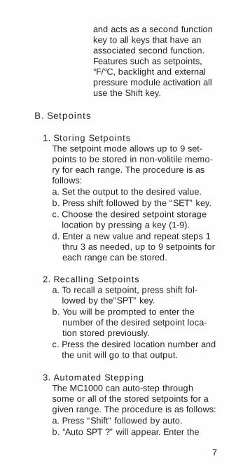
and acts as a second functionkey to all keys that have anassociated second function.Features such as setpoints,°F/°C, backlight and externalpressure module activation alluse the Shift key.
B. Setpoints
1. Storing SetpointsThe setpoint mode allows up to 9 set-points to be stored in non-volitile memo-ry for each range. The procedure is asfollows:a. Set the output to the desired value.b. Press shift followed by the “SET” key.c. Choose the desired setpoint storage
location by pressing a key (1-9).d. Enter a new value and repeat steps 1
thru 3 as needed, up to 9 setpoints foreach range can be stored.
2. Recalling Setpointsa. To recall a setpoint, press shift fol-
lowed by the”SPT” key.b. You will be prompted to enter the
number of the desired setpoint loca-tion stored previously.
c. Press the desired location number andthe unit will go to that output.
3. Automated SteppingThe MC1000 can auto-step throughsome or all of the stored setpoints for agiven range. The procedure is as follows:a. Press “Shift” followed by auto.b. “Auto SPT ?” will appear. Enter the
7
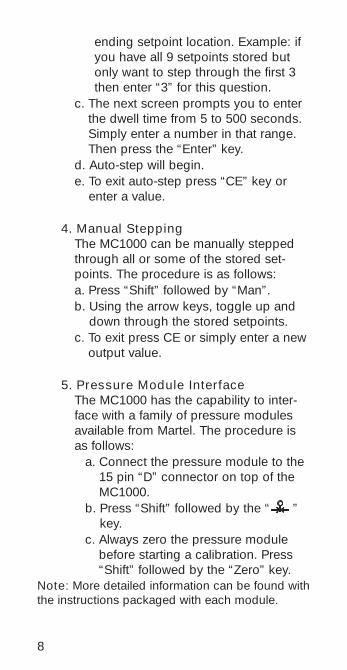
ending setpoint location. Example: ifyou have all 9 setpoints stored butonly want to step through the first 3then enter “3” for this question.
c. The next screen prompts you to enterthe dwell time from 5 to 500 seconds.Simply enter a number in that range.Then press the “Enter” key.
d. Auto-step will begin.e. To exit auto-step press “CE” key or
enter a value.
4. Manual SteppingThe MC1000 can be manually steppedthrough all or some of the stored set-points. The procedure is as follows:a. Press “Shift” followed by “Man”.b. Using the arrow keys, toggle up and
down through the stored setpoints.c. To exit press CE or simply enter a new
output value.
5. Pressure Module InterfaceThe MC1000 has the capability to inter-face with a family of pressure modulesavailable from Martel. The procedure isas follows:
a. Connect the pressure module to the15 pin “D” connector on top of theMC1000.
b. Press “Shift” followed by the “ ”key.
c. Always zero the pressure modulebefore starting a calibration. Press“Shift” followed by the “Zero” key.
Note: More detailed information can be found withthe instructions packaged with each module.
8
9
10
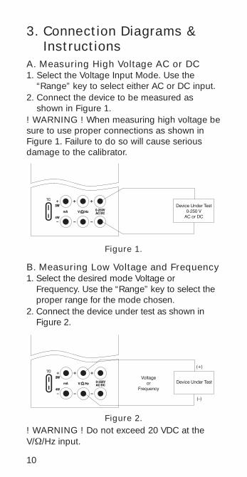
3. Connection Diagrams &Instructions
A. Measuring High Voltage AC or DC1. Select the Voltage Input Mode. Use the
“Range” key to select either AC or DC input.2. Connect the device to be measured as
shown in Figure 1.! WARNING ! When measuring high voltage besure to use proper connections as shown inFigure 1. Failure to do so will cause seriousdamage to the calibrator.
B. Measuring Low Voltage and Frequency 1. Select the desired mode Voltage or
Frequency. Use the “Range” key to select theproper range for the mode chosen.
2. Connect the device under test as shown inFigure 2.
Figure 1.
Figure 2.! WARNING ! Do not exceed 20 VDC at theV/Ω/Hz input.
11
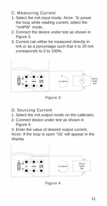
C. Measuring Current1. Select the mA input mode. Note: To power
the loop while reading current, select the“mAPW” mode.
2. Connect the device under test as shown inFigure 3.
3. Current can either be measured directly inmA or as a percentage such that 4 to 20 mAcorresponds to 0 to 100%.
D. Sourcing Current1. Select the mA output mode on the calibrator.2. Connect device under test as shown in
Figure 4.3. Enter the value of desired output current.Note: If the loop is open “OL” will appear in thedisplay.
Figure 3.
Figure 4.
12
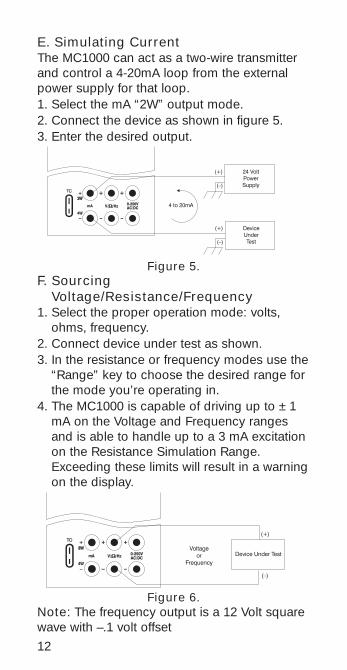
E. Simulating CurrentThe MC1000 can act as a two-wire transmitterand control a 4-20mA loop from the externalpower supply for that loop.1. Select the mA “2W” output mode.2. Connect the device as shown in figure 5.3. Enter the desired output.
F. SourcingVoltage/Resistance/Frequency
1. Select the proper operation mode: volts,ohms, frequency.
2. Connect device under test as shown.3. In the resistance or frequency modes use the
“Range” key to choose the desired range forthe mode you’re operating in.
4. The MC1000 is capable of driving up to ±1mA on the Voltage and Frequency rangesand is able to handle up to a 3 mA excitationon the Resistance Simulation Range.Exceeding these limits will result in a warningon the display.
Figure 6.Note: The frequency output is a 12 Volt squarewave with –.1 volt offset
Figure 5.
13
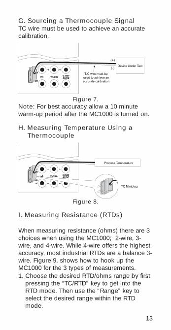
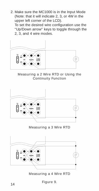
I. Measuring Resistance (RTDs)
When measuring resistance (ohms) there are 3choices when using the MC1000; 2-wire, 3-wire, and 4-wire. While 4-wire offers the highestaccuracy, most industrial RTDs are a balance 3-wire. Figure 9. shows how to hook up theMC1000 for the 3 types of measurements.1. Choose the desired RTD/ohms range by first
pressing the “TC/RTD” key to get into theRTD mode. Then use the “Range” key toselect the desired range within the RTDmode.
H. Measuring Temperature Using aThermocouple
Figure 8.
G. Sourcing a Thermocouple SignalTC wire must be used to achieve an accuratecalibration.
Figure 7.Note: For best accuracy allow a 10 minutewarm-up period after the MC1000 is turned on.
14
2. Make sure the MC1000 is in the Input Mode(Note: that it will indicate 2, 3, or 4W in theupper left corner of the LCD).To set the desired wire configuration use the“Up/Down arrow” keys to toggle through the2, 3, and 4 wire modes.
Measuring a 2 Wire RTD or Using theContinuity Function
Measuring a 3 Wire RTD
Measuring a 4 Wire RTD
Figure 9.

15
4. Serial CommunicationsThe MC1000 calibrator is equipped with a RS-232 serial communications port, which is locat-ed on the top of the case. Note: The user will require a special RS-232cable to connect the calibrator to a computer orterminal.
CommunicationOnce the cable is attached, set the communica-tions program settings as follows:
Baud Rate = 9600Data Bits = 8 Stop Bits = 1 Parity = None Flow Control = Xon/Xoff
J. Sourcing Resistance Into a RTDTransmitter
1. As described previously in section F theMC1000 can source resistance in a RTDTransmitter or measuring device. In manycases the unit under test will require a 3 or 4wire connection to achieve best accuracy.Refer to Figure 10 for connection information.
Figure 10.
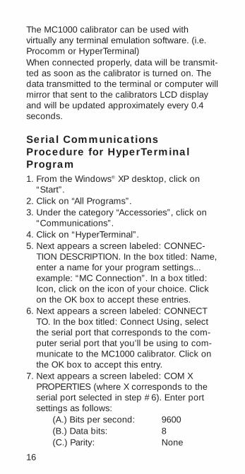
The MC1000 calibrator can be used with virtually any terminal emulation software. (i.e.Procomm or HyperTerminal) When connected properly, data will be transmit-ted as soon as the calibrator is turned on. Thedata transmitted to the terminal or computer willmirror that sent to the calibrators LCD displayand will be updated approximately every 0.4seconds.
Serial CommunicationsProcedure for HyperTerminalProgram1. From the Windows® XP desktop, click on
“Start”. 2. Click on “All Programs”.3. Under the category “Accessories”, click on
“Communications”. 4. Click on “HyperTerminal”. 5. Next appears a screen labeled: CONNEC-
TION DESCRIPTION. In the box titled: Name,enter a name for your program settings...example: “MC Connection”. In a box titled:Icon, click on the icon of your choice. Clickon the OK box to accept these entries.
6. Next appears a screen labeled: CONNECTTO. In the box titled: Connect Using, selectthe serial port that corresponds to the com-puter serial port that you’ll be using to com-municate to the MC1000 calibrator. Click onthe OK box to accept this entry.
7. Next appears a screen labeled: COM XPROPERTIES (where X corresponds to theserial port selected in step #6). Enter portsettings as follows:
(A.) Bits per second: 9600(B.) Data bits: 8(C.) Parity: None
16

(D.) Stop Bits: 1(E.) Flow Control: Xon/XoffClick OK box to accept these entries.
8. Hook up the MC1000 calibrator to the PC uti-lizing the special Martel Electronics RS-232cable as follows:
(A.) Plug the 9 pin connector end of thecable to the appropriate serial porton the computer.
(B.) With the MC1000 calibratorswitched off, plug the other end ofthe cableplug the other end of thecable into the DB-15 connector onthe top of the MC1000 calibrator.
9. Power up the MC1000 calibrator per theappropriate instruction manual. The computerscreen should now be displaying data beingsent directly from the MC1000 calibrator.
Note: You may wish to save these settingswhen exiting HyperTerminal. If so, click on theOK box when prompted “Do you want to saveX?”, where X corresponds to the name enteredin Step #5.
Computer Controlled Operation The MC1000 calibrator can be operated remote-ly via a computer or terminal. When connectedto a computer, via the RS-232 serial data portand appropriate cabling, the user may controlthe calibrator functions remotely by utilizing sim-ple computer keyboard commands. The following chart details which computer keyscontrol which MC1000 calibrator functions:
17
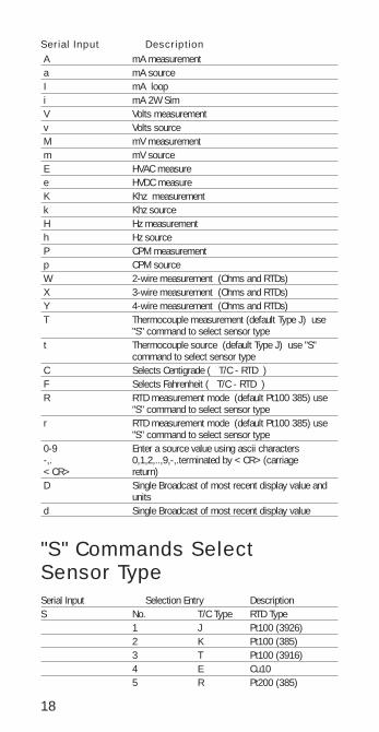
Serial Input DescriptionA mA measurement a mA source I mA loopi mA 2W SimV Volts measurementv Volts sourceM mV measurementm mV sourceE HVAC measuree HVDC measureK Khz measurementk Khz sourceH Hz measurementh Hz sourceP CPM measurementp CPM sourceW 2-wire measurement (Ohms and RTDs)X 3-wire measurement (Ohms and RTDs)Y 4-wire measurement (Ohms and RTDs)T Thermocouple measurement (default Type J) use
"S" command to select sensor typet Thermocouple source (default Type J) use "S"
command to select sensor typeC Selects Centigrade ( T/C - RTD ) F Selects Fahrenheit ( T/C - RTD )R RTD measurement mode (default Pt100 385) use
"S" command to select sensor typer RTD measurement mode (default Pt100 385) use
"S" command to select sensor type0-9 Enter a source value using ascii characters -,. 0,1,2,..,9,-,.terminated by <CR>(carriage <CR> return) D Single Broadcast of most recent display value and
unitsd Single Broadcast of most recent display value
"S" Commands Select Sensor TypeSerial Input Selection Entry DescriptionS No. T/C Type RTD Type
1 J Pt100 (3926)2 K Pt100 (385)3 T Pt100 (3916)4 E Cu105 R Pt200 (385)
18

19
Serial Input Selection Entry DescriptionS No. T/C Type RTD Type
6 S Pt500 (385)7 B Pt1000 (385)8 L NI1209 U YSIA N OHMSB mV
® Microsoft, Windows, Windows NT, and MS-DOS are registeredtrademarks of Microsoft Corporation. All other product names orservices identified throughout this manual are registered trade-marks or trademarks of their respective companies.
5. MaintenanceA. Power RequirementsThe MC1000 operates on 4 AA alkaline batteriesonly.
B. CalibrationThe MC1000 should hold its rated specifica-tions for a minimum of one year. Given this,annual re-calibration is required for best per-formance. See the customer service section (7.)to contact Martel for re-calibration information.
C. Field Replacement FuseMC1000 comes with a field replaceable mini-fuse. This fuse protects the MC1000 inputs andoutputs. If an overload condition occurs and ablown fuse is suspected perform the followingfuse check/replacement procedure:1. Remove the four screws on the rear of the
MC1000 that hold the enclosure together.NOTE: Two of the screws are under the bat-tery compartment door.
2. With the case top open, locate the two sock-eted mini fuses mounted near the input/out-put connection jacks.
20
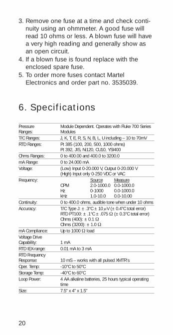
6. Specifications
Pressure Module Dependent. Operates with Fluke 700 Series Ranges: Modules T/C Ranges: J, K, T, E, R, S, N, B, L, U including – 10 to 70mV RTD Ranges: Pt 385 (100, 200, 500, 1000 ohms)
Pt 392, JIS, Ni120, CU10, YSI400Ohms Ranges: 0 to 400.00 and 400.0 to 3200.0mA Range: 0 to 24.000 mAVoltage: (Low) Input 0-20.000 V, Output 0-20.000 V
(High) Input only 0-250 VDC or VACFrequency: Source Measure
CPM 2.0-1000.0 0.0-1000.0 Hz 0-1000 0.0-1000.0 kHz 1.0-10.0 0.0-10.00
Continuity: 0 to 400.0 ohms, audible tone when under 10 ohmsAccuracy: T/C Type J: ±.3°C ±10 µV (±0.4°C total error)
RTD PT100: ±.1°C ±.075 Ω (±0.3°C total error)Ohms (400): ±0.1 ΩOhms (3200): ±1.0 Ω
mA Compliance: Up to 1000 Ω loadVoltage Drive Capability: 1 mARTD IEX-range: 0.01 mA to 3 mARTD Frequency Response: 10 mS – works with all pulsed XMTR’sOper. Temp: -10°C to 50°CStorage Temp: -40°C to 60°CLoop Power: 4 AA alkaline batteries, 25 hours typical operating
timeSize: 7.5" x 4" x 1.5"
3. Remove one fuse at a time and check conti-nuity using an ohmmeter. A good fuse willread 10 ohms or less. A blown fuse will havea very high reading and generally show asan open circuit.
4. If a blown fuse is found replace with theenclosed spare fuse.
5. To order more fuses contact MartelElectronics and order part no. 3535039.

21
Range & AccuracyRange Min Max Accuracy
(% of reading ±counts)
V Read (low) 0.000 20.000 0.015% ±2VDC Read (high) 0.0 250.0 0.05% ±2VAC Read (high) 0.0 250.0 0.5% ±2V Source 0.000 20.000 0.015% ±2mV Read -10.00 75.00 0.015% ±2mV Source -10.00 75.00 0.015% ±2
mA Read 0.000 24.000 0.015% ± 2mA Source 0.000 24.000 0.015% ± 2
CPM Source 2.0 1000.0 0.05% Hz Source 1 1000 0.05%
KHz Source 1.0 10.0 0.25% CPM Read 0.0 1000.0 0.05% ± 1Hz Read 0.0 1000.0 0.05% ± 1KHz Read 0.00 10.00 0.05% ± 1
Range Min Max Accuracy Ohms Read (low) 0.00 400.00 0.1 ohmOhms Read (high) 400.0 1500.0 0.5 ohm
1500.1 3200.0 1.0 ohm
Range Min Max Excitation Accuracy Current
Ohms Source (low) 5.00 400.00 0.1 to 0.5 mA 0.15 ohm5.00 400.00 0.5 to 3 mA 0.1 ohm
Ohms Source (high) 400.0 1500.0 0.05 to 0.8 mA 0.5 ohm1500.0 3200.0 0.05 to 0.4 mA 1.0 ohm
Thermocouple Read and Source (All errors included)Range Min Max Accuracy J Thermocouple -200.0 0.0 0.6°C
0.0 1200.0 0.4°CK Thermocouple -200.0 0.0 0.8°C
0.0 1370.0 0.5°CT Thermocouple -200.0 0.0 0.8°C
0.0 400.0 0.5°CE Thermocouple -200.0 0.0 0.5°C
0.0 950.0 0.4°CR Thermocouple -20 0.0 2.49°C
0 500 1.7°C500 1750 1.3°C
S Thermocouple -20 0 2.4°C0 500 1.7°C
500 1750 1.4°CB Thermocouple 600 800 2.1°C
800 1000 1.7°C1000 1800 1.3°C
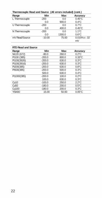
Thermocouple Read and Source (All errors included) (cont.)Range Min Max Accuracy L Thermocouple -200 0.0 0.45°C
0.0 900.0 0.4°CU Thermocouple -200 0.0 0.7°C
0.0 400.0 0.45°CN Thermocouple -200 0.0 1.1°C
0.0 1300.0 0.6°CmV Read/Source -10.00 75.00 0.015% ±.02
mV
RTD Read and SourceRange Min Max AccuracyNi120 (672) -80.0 260.0 0.2°CPt100 (385) -200.0 800.0 0.33°CPt100(3926) -200.0 630.0 0.3°CPt100(3916) -200.0 630.0 0.3°CPt200(385) -200.0 630.0 0.8°CPt500(385) -200.0 500.0 0.3°C
500.0 630.0 0.4°CPt1000(385) -200.0 100.0 0.2°C
100.0 630.0 0.3°CCu10 -100.0 250.0 2.2°CCu50 -180.0 200.0 0.5°CCu100 -180.0 200.0 0.3°CYSI400 15.00 50.00 0.05°C
22
7. WarrantyMartel Electronics Corporation warrants allproducts against material defects and work-manship for a period of twelve (12) monthsafter the date of shipment. Problems or defectsthat arise from misuse or abuse of the instru-ment are not covered. If any product is to bereturned, a “Return Material Authorization” num-ber must be obtained from our CustomerService Department. This number must be indi-cated on the return package as notice to ourReceiving Department to accept the shipment.Any package not so marked will not be accept-ed and will be returned to the shipper. Martelwill not be responsible for damage as a resultof poor return packaging. Out of warrantyrepairs and recalibration will be subject to spe-cific charges. Under no circumstances willMartel Electronics be liable for any device orcircumstance beyond the value of the product.
23


Rev G 10/08 0219041
Corporate Office:www.martelcorp.com
e-mail: [email protected]: (603) 434-1433 800-821-0023
Fax: (603) 434-1653
Martel Electronics3 Corporate Park Dr.
Derry, NH 03038