Embed Size (px)
Citation preview
;MC-Tq-93-14
AEROSPACt: REPORT NC)TR-0091 (6945,03)-6AD-A263 026
E1 LECTE ISAPRl 9 9 9 3 U
• C DJ
Lubricants for High-Vacuum Applications
Prepared by
M. R. HILTON and P. D. FLEISCHAUERMechanics and Materials Technology Center
Technology Operations
15 March 1993
Prepared for
SPACE AND MISSILE SYSTEMS CENTERAIR FORCE MATERIEL COMMAND
Los Angeles Air Force BaseP. 0. Box 92960
00 Los Angeles, CA 90009-2960
Engineering and Technology Group
__THE AEROSPACE CORPORATIONEl Segundo, California
APPROVED FOR PUBLIC RELEASE;DISTRIBUTION UNLIMITED
nI4 1 6I3

This report was submitted by The Aerospace Corporation, El Segundo, CA 90245-4691,under Contract No. F04701-88-C-0089 with the Space and Missile Systems Center, P. 0.Box 92960, Los Angeles, CA 90009-2960. It was reviewed and approved for TheAerospace Corporation by R. W. Fillers, Principal Director, Mechanics and MaterialsTechnology Center. Captain Borden was the project officer for the Mission-OrientedInvestigation and Experimentation (MOLE) program.
This report has been reviewed by the Public Affairs Office (PAS) and is releasable to theNational Technical Information Service (NTIS). At NTIS, it will be available to the generalpublic, including foreign nationals.
This technical report has been reviewed and is approved for publication. Publication of thisreport does not constitute Air Force approval of the report's findings or conclusions, It ispublished only for the exchange and stimulation of ideas
MARK W. BORDEN, CAPT, USAF WILLIAM KYLE SNEDDON, CAPT, USAFSSUSI/SSULI Project Officer MOIE Program Manager

UNCLASSIFIEDSECURITY CLASSIFICATION OF THIS PAGE
REPORT DOCUMENTATION PAGE1, REPORT SECURITY CLASSIFICATION l1 RESTRICTIVE MARKfNGS
Unclassified2a. SECURITY CLASSIFICATION AUTHORITY 3. DISTRIBuTIONAVALABiLITY OF REPORT
2b. DECLASSIFICATIONiGOWNGRADING SCHEDULE Approved for public release;distribution unlimited
4. PERFORMING ORGANIZATION REPORT NUMBER(S) 5 MONITORING ORGANIZATION REPORT NJl``BER(S)
TR-0091 (6945-03)-6 SMC-TR-93-146a. NAME OF PERFORMING ORGANIZATION 6o OFFiCE SYMBOL 7a NAME OF MONITOR•ING ORGANIZAT ON
The Aerospace Corporation Sat adM slS tes ne
Technology Operations Space and Missile Systems Center
6c- ADDRESS (City, State, and ZIP Code) 7b ADDRESS (City. State, and ZIP Codej
Los Angeles Air Force BaseEl Segundo, CA 90245-4691 Los Angeles, CA 90009-2960
Ba. NAME OF FUNGINGSPONSORING 8b. OFFICE SYMBOL 9. PROCUREMENT INSTRUMENT IDENTIFICATION NUMBERORGANIZATION (ffapphicable)
F04701-88-C-0089
8c. ADDRESS (City, State, and ZIP Code) 10. SOURCE OF FUNDING NUMBERS
PROGRAM PROJECT TASK WORK UNITELEMENT NO. NO. NO. ACCESSION NO.
11. TITLE (Include Securay Classification)
Lubricants for High-Vacuum Applications
,2. PERSONAL AUTHOR(S)
Hilton, Michael R.; and Fleischauer, Paul D.13a. TYPE OF REPORT 13b. TIME COVERED 14. DATE OF REPORT (Year. Month. Day) 15. PAGECOUNT
FROM TO_ 15 March 1993 6016. SUPPLEMENTARY NOTATION
17. COSATI CODES 18. SUBJECT TERMS (Continue on reverse if necessary and identify by block number)
FIELD GROUP SUB-GROUP Bearings Lubricants Oils VacuumCoatings Mechanisms Space EnvironmentGreases MoS2 Tribology
19. ABSTRACT (Continue on reverse if necessary and ,dentiy by block number)
This report reviews the selection criteria and performance of lubricants in vacuum environments found interrestrial equipment and in (and around) space vehicles. Vacuum, mechanical, and thermal conditions ofsuch lubricant use are outlined. Tribology issues are defined that should be considered in initial design ofsystems used in terrestrial equipment or space vehicles. The types of vacuum lubricants that are available(dry or solid, liquid, or grease) are reviewed, their properties and applicability to general situations areassessed, and the option of not lubricating is discussed. Examples of specific applications and performancedata for lubricants in space and on earth are presented.
20. DISTRIBUTION/AVAILABILITY OF ABSTRACT 21. ABSTRACT SECURITY CLASSIFICATION
I UNCLASSIFIED/UNLIMITED ['m SAME AS RPT. [ O OTIC USERS Unclassified22a. NAME OF RESPONSIBLF 11V1""•UAL 22b, TELEPHONE (Include Area Code) 22c. OFFICE SYMBOL
0D FORM 1473,84 MAR 83 APR edition may be used until exhausted. SECURITY CLASSIFICATION OF THIS PAGEAll other ed•tions are obsolete. UNCLASSIFIED
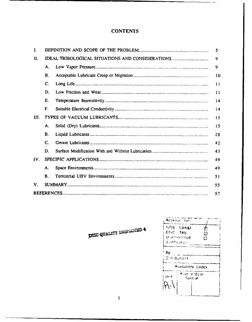
CONTENTS
I. DEFINITION AND SCOPE OF THE PROBLEM ............................................................ 5
1I. IDEAL TRIBOLOGICAL SITUATIONS AND CONSIDERATIONS .............................. 9
A. Low Vapor Pressure ............................................................................................... 9
B. Acceptable Lubricant Creep or Migration ............................................................. 10
C. Long Life .............................................................................................................. II
D. Low Friction and Wear ........................................................................................... 11
E. Temperature Insensitivity ....................................................................................... 14
F. Suitable Electrical Conductivity ............................................................................. 14
III. TYPES OF VACUUM LUBRICANTS ............................................................................ 15
A. Solid (Dry) Lubricants ......................................................................................... 15
B. Liquid Lubricants .................................................................................................. 28
C. Grease Lubricants ................................................................................................ 42
D. Surface Modification W ith and Without Lubrication .............................................. 43
IV. SPECIFIC APPLICATIONS .......................................... 49
A. Space Environments ............................................ 49
B. Terrestrial UHV Environments .............................................................................. 51
V. SUMMARY .................................................................................................................. 55
REFERENCES ......................................................................................................................... 57
alýCJZD 4 ThS CRA&iS01i€: rA8[
By
A vdildbOlity Codes
l u'tc Idl
I &3 .•! i q tcd
FIGURES
I. Friction coefficient of various types of MoS2 as a function of cyclesin pin-on-disk tests ......................................................................... 20
2. Reduction in vapor pressure as a function of percent oil loss for threeoils: (1) mineral oil JSRG 40), (2) poly-a--olefin INye 179), and(3) polyolester [Nye UC7j .................................................... 31
3. Schematic of a bearing configuration showing a labyrinth seal ........ ..... .......... 32
4. Viscosity versus temperature for a homologous series of super-refined mineral oils ........................................... ................ 35
5. Nominal molecular structure of selected fluid lubricants for space/vacuum. applications ................................................... ............ 38
6. Life-test results for various lubricants investigated with a boundarylubricant screening test and an oscillatory scanner-bearing test ......... ........... 40
TABLES
1. Potential Solid Lubricants for Use in Vacuum ............................... 16
2. Relative Merits of Solid and Liquid Lubricants for Use in Vacuum ................................ 17
3. Plastics and Fillers for Self-Lubricating Composites ......................................... 26
4. Some Self-Lubricating Composites and Their Possible Uses in Space ............................ 27
5. Properties of Selected Fluid Lubricants ......................................................................... 30
6. Factors That Influence the Degradation of PFPE Fluids ......................... 36
7. Tribology Components: Requirements and Technology "Solutions"for Space A pplications .................................................................................................. 50
3
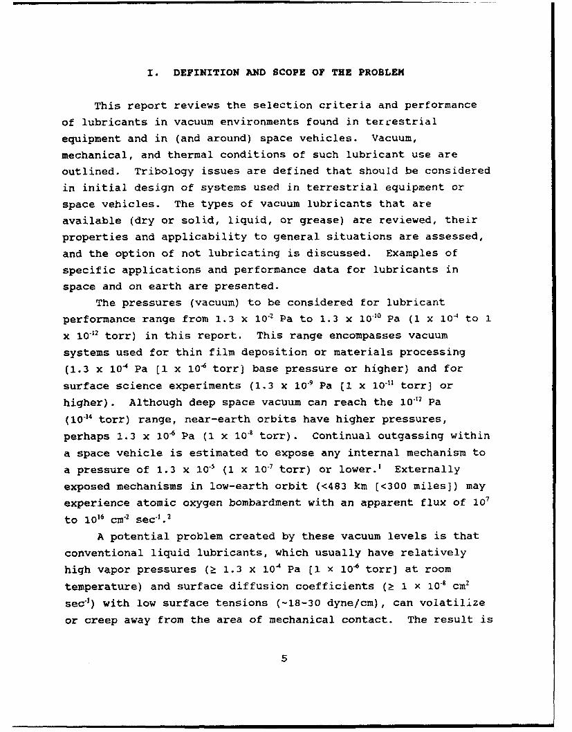
I. DEFINITION AND SCOPE OF THE PROBLEM
This report reviews the selection criteria and performance
of lubricants in vacuum environments found in terrestrial
equipment and in (and around) space vehicles. Vacuum,
mechanical, and thermal conditions of such lubricant use are
outlined. Tribology issues are defined that should be considered
in initial design of systems used in terrestrial equipment or
space vehicles. The types of vacuum lubricants that are
available (dry or solid, liquid, or grease) are reviewed, their
properties and applicability to general situations are assessed,
and the option of not lubricating is discussed. Examples of
specific applications and performance data for lubricants in
space and on earth are presented.
The pressures (vacuum) to be considered for lubricant
performance range from 1.3 x 10.2 Pa to 1.3 x 10"10 Pa (1 x 10⁴ to 1
x 10•2 torr) in this report. This range encompasses vacuum
systems used for thin film deposition or materials processing
(1.3 x 10⁴ Pa [l x 10- torr] base pressure or higher) and for
surface science experiments (1.3 x 10*9 Pa (I x 10-1 torr] or
higher). Although deep space vacuum can reach the 10-12 Pa
(10-14 torr) range, near-earth orbits have higher pressures,
perhaps 1.3 x 10⁶ Pa (I x 10-8 torr). Continual outgassing within
"a space vehicle is estimated to expose any internal mechanism to
"a pressure of 1.3 x 10⁻⁵ (1 x 10- torr) or lower.1 Externally
exposed mechanisms in low-earth orbit (<483 km [<300 miles]) may
experience atomic oxygen bombardment with an apparent flux of 107
to 1016 cm-2 sec-'. 2
A potential problem created by these vacuum levels is that
conventional liquid lubricants, which usually have relatively
high vapor pressures (Ž 1.3 x 10⁴ Pa [1 x 10⁶ torr] at room
temperature) and surface diffusion coefficients (Ž 1 x 10⁻⁸ cm2
sec"1) with low surface tensions (-18-30 dyne/cm), can volatilize
or creep away from the area of mechanical contact. The result is
5
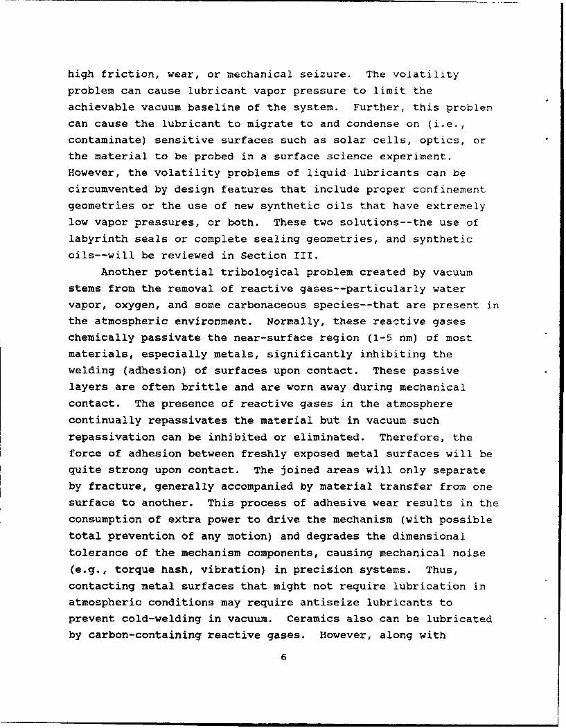
high friction, wear, or mechanical seizure. The volatility
problem can cause lubricant vapor pressure to limit theachievable vacuum baseline of the system. Further, this problem
can cause the lubricant to migrate to and condense on (i.e.,contaminate) sensitive surfaces such as solar cells, optics, or
the material to be probed in a surface science experiment.
However, the volatility problems of liquid lubricants can be
circumvented by design features that include proper confinement
geometries or the use of new synthetic oils that have extremely
low vapor pressures, or both. These two solutions--the use oflabyrinth seals or complete sealing geometries, and synthetic
oils--will be reviewed in Section III.
Another potential tribological problem created by vacuumstems from the removal of reactive gases--particularly water
vapor, oxygen, and some carbonaceous species--that are present inthe atmospheric environment. Normally, these reactive gases
chemically passivate the near-surface region (1-5 nm) of most
materials, especially metals, significantly inhibiting the
welding (adhesion) of surfaces upon contact. These passive
layers are often brittle and are worn away during mechanicalcontact. The presence of reactive gases in the atmosphere
continually repassivates the material but in vacuum such
repassivation can be inhibited or eliminated. Therefore, the
force of adhesion between freshly exposed metal surfaces will bequite strong upon contact. The joined areas will only separateby fracture, generally accompanied by material transfer from one
surface to another. This process of adhesive wear results in theconsumption of extra power to drive the mechanism (with possible
total prevention of any motion) and degrades the dimensional
tolerance of the mechanism components, causing mechanical noise
(e.g., torque hash, vibration) in precision systems. Thus,
contacting metal surfaces that might not require lubrication inatmospheric conditions may require antiseize lubricants to
prevent cold-welding in vacuum. Ceramics also can be lubricatedby carbon-containing reactive gases. However, along with
6

semiconductors and polymers, ceramics are not as susceptible to
the "cold-welding" phenomenon as are metals.
There are two categories of systems in which ultrahigh-vacuum lubricants are needed: (1) systems in terrestrial vacuum
chambers and (2) systems in space vehicles. Category I includes
chambers used for surface science experiments, analytical
instruments such as electron microscopes, thermal vacuum testing
chambers, thin film deposition chambers, and other materials
processing equipment primarily used in the semiconductor
industry. Such systems often have manipulators to move objects
within the most critical vacuum region. Contamination by the
lubricant is a prime issue for terrestrial vacuum systems,
whereas lifetime is a lesser concern because the lubricant can be
periodically replaced by breaking vacuum. In Category 2 systems,
those in space vehicles, human intervention is essentially
impossible (except infrequently, when a satellite in low-earth
orbit can be retrieved by a manned shuttle). Therefore, both
lifetime and contamination are of great concern.
Although the conditions of mechanical contact in vacuum
systems are varied, some generalizations can be made. Most
mechanisms do not operate continuously, so there are periods of
boundary contact (when lubricant film thickness is less than the
contacting surface roughness) between component surfaces.
Similarly, boundary contact also develops when oscillating
mechanisms change direction. In such situations, the chemical
interaction of contacting surfaces, often modified by the
presence of lubricants, is critically important. Both sliding
and rolling elements are designed into vacuum systems. Each
element requires proper consideration of lubricant specification
to prevent cold-welding, to promote low torque noise performance,
and to ensure adequate service life. Other mechanical parameters
that are important in the design of moving assemblies and in the
selection of the proper lubricant include the expected loads and
contact stresses, the geometry of the contact (the conformity of
the surfaces and the possibility of lubricant confinement), and
7

the relative velocities (rotational speed) of the contacting
surfaces. Temperatures encountered by vacuum components usually
range from 0 to 75"C, although mechanisms within infrared sensors
are cryogenically cooled. Lubricants functioning above 2000 C are
beyond the scope of this text; interested readers are referred
elsewhere.
Another possible condition for lubricants in vacuum is the
requirement for electrical conductivity. Some satellites
maintain attitude stability by spinning the entire vehicle while
the antennas and sensors are continually despun to allow them to
remain pointed at fixed objects. Other satellites have rotating
panels of solar cells that track the sun to maintain constant
power and to keep batteries charged. Electrical signals and
power must be transmitted across a rotating interface, which
consists of sliding wipers having a conductive lubricant. This
issue will be explored later in the text. Yet another condition
is the possible use, in satellite systems, of high-speed
bearings, such as those in fly wheels used for momentum
stabilization and in turbomachinery (rocket motors). Because of
frictional heating in such bearings, lubricants (usually oils or
greases) are required that can conduct heat efficiently among
rolling elements and maintain low overall operating temperatures.
(The unusual case of liquid hydrogen and liquid oxygen pumps as
used in the space shuttle main engines involves solid lubrication
of the bearings with fluid [fuel] coolants. The involvement of
the fluids in lubrication is probably minimal.)
8
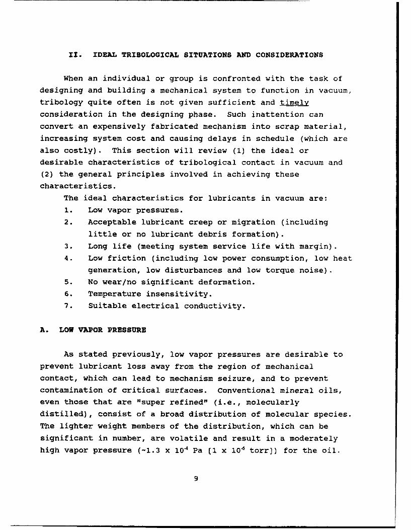
II. IDEAL TRIBOLOGICAL SITUATIONS AND CONSIDERATIONS
When an individual or group is confronted with the task ofdesigning and building a mechanical system to function in vacuum,
tribology quite often is not given sufficient and timely
consideration in the designing phase. Such inattention can
convert an expensively fabricated mechanism into scrap material,
increasing system cost and causing delays in schedule (which arealso costly). This section will review (1) the ideal or
desirable characteristics of tribological contact in vacuum and
(2) the general principles involved in achieving these
characteristics.
The ideal characteristics for lubricants in vacuum are:
1. Low vapor pressures.
2. Acceptable lubricant creep or migration (including
little or no lubricant debris formation).3. Long life (meeting system service life with margin).
4. Low friction (including low power consumption, low heat
generation, low disturbances and low torque noise).
5. No wear/no significant deformation.
6. Temperature insensitivity.
7. Suitable electrical conductivity.
A. LOW VAPOR PRESSURE
As stated previously, low vapor pressures are desirable to
prevent lubricant loss away from the region of mechanicalcontact, which can lead to mechanism seizure, and to prevent
contamination of critical surfaces. Conventional mineral oils,
even those that are "super refined" (i.e., molecularly
distilled), consist of a broad distribution of molecular species.
The lighter weight members of the distribution, which can be
significant in number, are volatile and result in a moderatelyhigh vapor pressure (-1.3 x 10⁴ Pa (1 x 10⁶ torr]) for the oil.
9
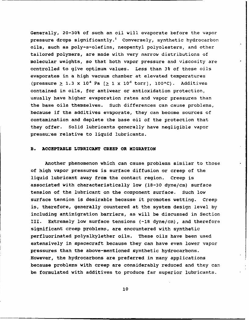
Generally, 20-30% of such an oil will evaporate before the vapor
pressure drops significantly. 5 Conversely, synthetic hydrocarbon
oils, such as poly-a-olefins, neopentyl polyolesters, and other
tailored polymers, are made with very narrow distributions of
molecular weights, so that both vapor pressure and viscosity are
controlled to give optimum values. Less than 3% of these oils
evaporates in a high vacuum chamber at elevated temperatures
(pressure > 1.3 x 10⁴ Pa [> 1 x 10- torr], 100OC). Additives
contained in oils, for antiwear or antioxidation protection,
usually have higher evaporation rates and vapor pressures than
the base oils themselves. Such differences can cause problems,
because if the additives evaporate, they can become sources of
contamination and deplete the base oil of the protection that
they offer. Solid lubricants generally have negligible vapor
pressu:es relative to liquid lubricants.
B. ACCEPTABLE LUBRICANT CREEP OR MIGRATION
Another phenomenon which can cause problems similar to those
of high vapor pressures is surface diffusion or creep of the
liquid lubricant away from the contact region. Creep is
associated with characteristically low (18-30 dyne/cm) surface
tension of the lubricant on the component surface. Such low
surface tension is desirable because it promotes wetting. Creep
is, therefore, generally countered at the system design level by
including antimigration barriers, as will be discussed in Section
III. Extremely low surface tensions (-18 dyne/cm), and therefore
significant creep problems, are encountered with synthetic
perfluorinated polyalkylether oils. These oils have been used
extensively in spacecraft because they can have even lower vapor
pressures than the above-mentioned synthetic hydrocarbons.
However, the hydrocarbons are preferred in many applications
because problems with creep are considerably reduced and they can
be formulated with additives to produce far superior lubricants.
10
(Although not in common use at present, another class of oils
known as sila-hydrocarbons 6 offers potential advantages for
vacuum uses.)For solid lubricants, there is a similar concern about the
presence and migration of particulates generated from detached
film debris. This possible problem is not well documented.
Therefore, line-of-sight barriers and the effects of gravity
should be considered to contain particle migration. In space,
particulate motion may be exacerbated by the lack of gravity. On
earth, prudent designers should locate mechanisms below critical
surfaces or operations, allowing gravity to pull particles away
harmlessly.
C. LONG LIFE
A lubricant must have a long operational life to be
considered successful. However, long life in this sense is
relative to the anticipated service life of the mechanism. The
point is that a lubricant should be chosen that has an adequate
endurance life (including a reasonable safety margin) and not
necessarily the best endurance life, since other performance
properties and design issues (e.g., system complexity, system
production cost) also have to be considered.
D. LOW FRICTION AND WEAR
Low friction is important for vacuum mechanisms to reduce
the consumption of power, which on spacecraft is finite, since it
is supplied by batteries and solar cells. Low friction also
reduces heat generation. For mechanisms controlled
electronically or in a feedback loop, a stable ("hash-free")
friction coefficient (low noise) is particularly important to
maintain proper control. In spacecraft, attitude control is
maintained by either momentum transfer mechanisms (reaction
wheels, momentum wheels, or control-moment gyroscopes) or by
11

spinning most of the vehicle. Variable friction of the bearings
at the despin interface can cause the vehicle to wobble or
tumble.
Lubricants that promote low friction also retard wear and
plastic deformation of contacting surfaces. Such wear and
deformation can lead to loss of component tolerance, which, in
turn, may cause increased torque noise and/or variable torque
levels, or outright mechanism failure. At the atomic level,
reducing friction is synonymous with minimizing chemical bonding
between contacting surfaces. There is a positive relationship
between friction and chemical reactivity: the friction
coefficient of metals against themselves in vacuum correlates
with the position of the metal on the periodic table.7 (For
example, the d-shell metals on the left side of the table, which
are more reactive, have been found to have higher friction
coefficients.) Thus, it is desirable for the surfaces of
contacting components to have low chemical reactivity. The
lubricant modifies surface composition to achieve this reduced
reactivity. In unlubricated situations, low surface reactivity
favors the selection of polymers or ceramics.
Ceramics are particularly interesting because their bonding
properties not only yield lower surface reactivity but also
higher elastic modulus and strength. The latter two properties
help resist deformation and irreversible loss of tolerance. The
designer should only select component materials that have elastic
limits greater than the operational stresses of the mechanism to
avoid plastic deformation or fracture and subsequent loss of
component tolerance.
The ideal tribological contact can also be viewed from the
macroscopic continuum perspective. For example, the friction
coefficient between unlubricated or dry lubricated surfaces is:'
'S = (r,)(A)/W (Eq 1)
12

where A is the friction coefficient, T, is shear strength of the
weakest material or interface, A is the true contact area, and W
is the normal contact load. T, is related to kinetic friction
force, Fk, by:
F1 = (T,) (A) (Eq 2)
For a Hertzian contact in which a smooth sphere is sliding
against a flat surface, Eq 1 can be rewritten: 9
S= (s/W) (3R/4E)2 (Eq 3)
where R is the radius of the contacting sphere and E is the
effective modulus of the contacting materials. For a given load,
the use of a lubricant or surface modification process thatreduces the shear strength of the interface will reduce friction.
If the lubricant film or surface modified region is thin, the
load is supported primarily by the substrate. Increasing thesubstrate modulus decreases the contact area for a given load,
which also reduces friction.
The designer can vary the surface composition of components
directly or by placing lubricants on the contacting surfaces, as
will be discussed in Section III. Component sliding can, in
principle, occur by the shear or relative motion of atoms along
only two adjacent contacting lattice planes. Thus, the above
atomistic and macroscopic arguments mean that the ideal contactconsists of a thin surface zone (including the lubricant, if
present, and component surfaces) having low shear strength (or
low reactivity), with the bulk material(s) of the components
providing a high-modulus, underlying support. The ideal surface
zone or lubricant film thickness has been found to be between 0.5
and 1.0 um.9
13

E. TEMPERATURE INSENSITIVITY
Lubricants must provide acceptable friction performance
within the operational temperature limits of the system. Solid
lubricants generally have less temperature sensitivity than
liquids and greases (Section III). Again, the designer must
remember to consider all lubricants that have adequate
temperature characteristics for the given application, and not
necessarily to choose the lubricant with the best temperature
characteristics. The thermal conductivity characteristics must
also be viewed with similar criteria.
F. SUITABLE ELECTRICAL CONDUCTIVITY
For most mechanical contacts in vacuum, electrical
conductivity across the contacting surfaces and through the
lubricant is not an issue. However, conductive lubricants are
required in sliding electrical contacts found in many space
systems. These contacts transmit power and signals between
different spacecraft sections that move relative to each other,
i.e., motion often occurs between the main body of the spacecraft
and other subsystems such as solar cell arrays, antennas, and
sensors. As will be discussed in Section III, solid lubricant
composites are frequently used.
14
III. TYPES OF VACUUM LUBRICANTS
There are three types of lubricants used in vacuum
environments: solid (dry), liquid, and grease. There is also a
fourth "lubricant" or approach, which is to use no lubricant atall, but to rely instead on the low reactivity of the contacting
surfaces. In these cases, the component materials have to be
carefully chosen and, perhaps, have their surface compositions
modified to lower reactivity. Descriptions of most solid and
liquid space lubricants are given, together with conditions for
use, in the NASA handbook by McMurtrey.2 This reference is acomprehensive treatise that should be consulted before choosing a
vacuum lubricant. This section will define and review the
lubricants available, including an assessment of their favorable
and unfavorable properties. Whenever appropriate, methods ofapplication or processing will be reviewed.
A. SOLID (DRY) LUBRICANTS
There are four types of solid or dry lubricants available
for vacuum applications: soft metals, lamellar solids, polymers,or other soft solids (see Table 1). Composites of these four
types of lubricants or combinations of one or more of them with
matrix or support materials are also available. The majoradvantages of solid lubricants, as indicated in Table 2, are (1)
they have negligible vapor pressures and (2) some of them are
quite insensitive to temperature and therefore are the onlylubricants suitable for cryogenic or high temperature
applications. Accelerated testing is valid for solid lubricants,
if the same wear mechanism is operative at different test speeds
(which can be verified by microscopy). Since space missionsoften extend beyond 5 years, accelerated ground testing becomes
essential for qualification of new lubricants. Generally, solid
lubricants have lower friction coefficients in vacuum than
greases and can have lower friction coefficients than liquids.
i5
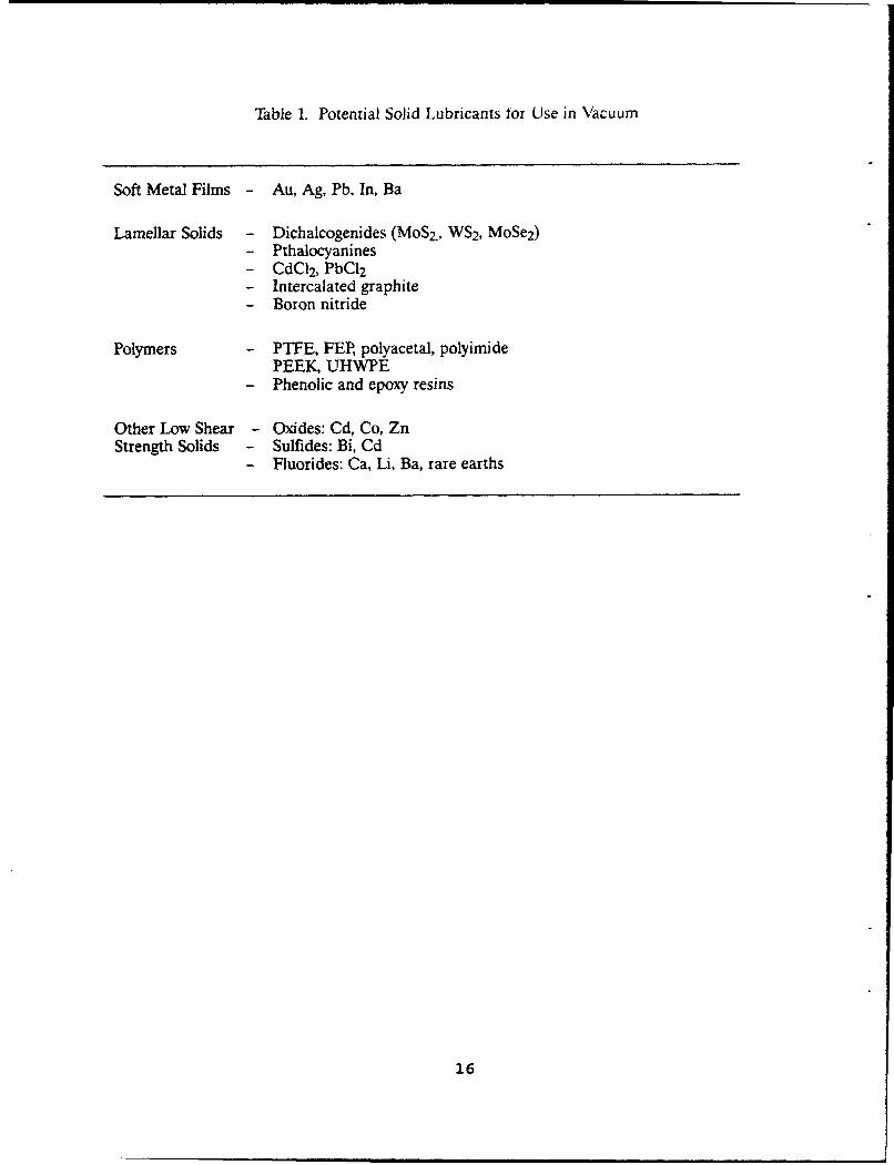
Table 1. Potential Solid Lubricants for Use in Vacuum
Soft Metal Films - Au, Ag, Pb, In, Ba
Lamellar Solids - Dichalcogenides (MoS2., WS2, MoSe 2)- Pthalocyanines- CdCI2, PbCI2- Intercalated graphite- Boron nitride
Polymers - PTFE, FEP, polyacetal, polyimidePEEK, UHWPE
- Phenolic and epoxy resins
Other Low Shear - Oxides: Cd, Co, ZnStrength Solids - Sulfides: Bi, Cd
- Fluorides: Ca, Li, Ba, rare earths
16
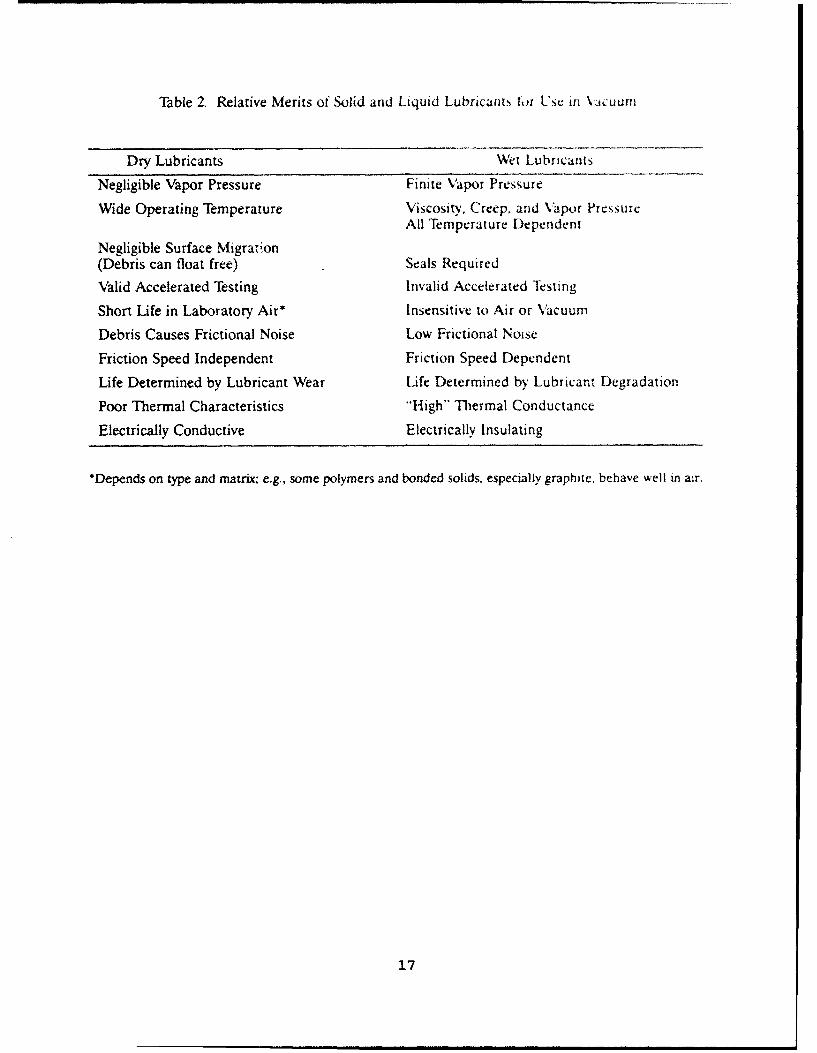
Table 2. Relative Merits of Solid and Liquid Lubricants ts f so in \Macuum
Dry Lubricants Wet Lubricants
Negligible Vapor Pressure Finite Vapor Pressure
Wide Operating Temperature Viscosity, Creep. and Vapor PressureAll Temperature Dependent
Negligible Surface Migration(Debris can float free) Seals Required
"Valid Accelerated Testing Invalid Accelerated Iesting
Short Life in Laboratory Air* Insensitive to Air or Vacuum
Debris Causes Frictional Noise Low Frictional Noise
Friction Speed Independent Friction Speed Dependent
Life Determined by Lubricant Wear Life Determined by Lubricant Degradation
Poor Thermal Characteristics "High" Thermal Conductance
Electrically Conductive Electrically Insulating
*Depends on type and matrix; e.g.. some polymers and bonded solids, especially graphite, behave well in air.
17
For example, MoS 2 films have been developed with friction
coefficients lower than 0.01. (Although Guiness" lists Teflon
as the material with the lowest friction coefficient known, at
0.02, MoS2 films can have considerably lower values, being as
low as 0.007 under the right conditions. 9)
The major disadvantage of solid lubricants is their shorter
lifetime relative to liquids or greases. Once a solid lubricant
is pushed out of the contact zone, lubricant resupply generally
does not occur (except for transfer film schemes, as described
shortly), as it does for liquids or greases. Also, failure is
quite abrupt (i.e., catastrophic as compared to graceful failure
observed for most fluid lubricants), often with no priorperformance degradation seen by the system operators. The solid
lubricant pushed out of the contact zone forms debris, which can
form bumps and lead to torque disturbances in precision bearings,
or can become unwanted particulate material.Solid lubricants can be applied either by rubbing
(burnishing) a powder or a solid block of lubricant against a
component surface, resulting in transfer of the lubricant to the
critical surface, or by applying the lubricant as a thin film to
the component prior to mechanism use. The rubbing approach can
be used to develop a source of lubricant resupply if some portionof the mechanism is fabricated from the lubricant. Ball bearing
cages (retainers) made of polymer-based composites or of leaded
bronze have been used in this way. The disadvantage of the
rubbing approach is that lubricant transfer can be sporadic or
uneven (nonuniform), yielding lubricant bumps or bare regions on
the contacting surfaces. For precision mechanisms, unacceptable
torque noise can result.
Solid lubricant films can be applied by rubbing or
burnishing, although careful procedures have to be followed to
maximize even coverage. Another alternative, for lamellar
compounds, is to mix the lubricant with a binder and a solvent,
and apply the mixture by dipping, painting, or spraying. The
18

resulting bonded films often require air or heat curing after
application. Bonded films are generally several micrometers
thick, which often does not allow for the lowest possible
friction of low-shear materials, and which is dimensionally
unsuitable (too thick) for many precision components. However,
the bonded film technology is well established and is quite
effective and appropriate for many low-cycle applications, such
as release mechanisms, journals, clamps, etc., that cannot
tolerate seizure.10' 12
Another approach to applying thin films of dry lubricants is
to use vacuum deposition techniques for uniform coverage of
components in precision systems. When film thickness is less
than 1 gm, low and steady friction has been obtained, as shown in
Figure 1. For precision mechanisms, the films can be applied by
sputtering, ion plating, or other ion-beam assisted techniques to
obtain even, controlled lubricant coverage. Ion cleaning of the
substrates prior to deposition can be used to improve film
adhesion to the components. A major disadvantage of solid
lubricant thin films is that there is no means of lubricant
resupply. Therefore, lubricant endurance life relative to system
service life is of prime importance when considering solid
lubricants.
.. Soft Metals
Soft metals, including lead, gold, silver, and indium, have
all been used as lubricants in vacuum applications. 13 Of these
metals, lead has had the most success and use. To apply lead,
burnishing or electroplating has been used; however, deposition
by ion plating provides the best adhesion and is preferred for
even (uniform) coverage. Optimum performance of lead and other
metals is achieved at approximately 1 gm thickness. Ion-plated
lead films have been particularly effective in spacecraft
bearings found in solar array drive mechanisms, especially in
19

0.3 i 1 i 13 BALL ON DISC
- 52100 STEELW BURNISHED MoS 2 20 N LOADu.. 0.2 -U-
00 SP01iAY-BONDED MoS2
90.
U- SPUTTERED MOS2
100 101 102 103 104 105 106 101
DISC REVOLUTIONS
Figure 1. Friction coefficient of various types of MoS 2as a function of cycles in pin-on-disk tests. [From E.W. Roberts and W. B. Price, Mat. Res. Soc. Symp. Proc.,140, 251 (1989).]
20

European satellites. Silver and gold are useful in situations
requiring electrical conductivity. However, silver is generallytoo hard for most applications, and gold work-hardens quite
easily. Lead remains soft at room temperatures, and there is
evidence which indicates that it can lubricate at 209K.13
2. Lamellar Solids
Lamellar solids in relatively wide use as lubricants include
the disulfides and diselenides of Mo, W, Nb, and Ta. Graphite is
also a lamellar solid lubricant, but the pure material is not
suitable for vacuum applications, as will be discussed shortly.4'12
(Some other doped or intercalated layered solids--such as
AgNbSe 2 _YSY [x = 0.1-1.0; y = 0.0-2.0] compounds, Ag0 33WSe2 , Cu 0 33WS2,
Cuo0 33NbSe2 , and Cu o.33NbSSe--have been investigated for their
lubrication properties, but they are not in wide use. 14 ) The
anisotropic, planar crystal structures of lamellar solids provide
low-shear planes for lubrication. These solids also have highload-bearing capacity when compressed in a direction
perpendicular to their low-shear planes. This load-bearing
capability of the lamellar solids is an advantage over solid
polymer lubricants.Of the lamellar solids, MoS 2 films deposited by sputtering
have been the most widely investigated and developed, since early
in the space programI5 and especially in the last few years. 16"
MoS 2 films have a lower friction coefficient than Pb films (•
0.01 vs 0.1 in vacuum, respectively), which lowers mechanism
torque and power consumption (always a concern on spacecraft).
MoS 2 films are also superior to Pb films in pure sliding
applications. Sputter-deposited MOS 2 has superior endurance and
a lower running friction than either burnished or bonded MoS 2 , as
shown in Figure 1.
The performance of sputter-deposited MoS2 is critically
dependent upon film microstructure, which includes composition,
21
morphology, crystallinity, and preferred orientation. 5 ,"8 These
properties, in turn, are very dependent upon deposition
conditions; the presence of water vapor during deposition is a
particularly insidious variable.19 The general trend in film
development in recent years has been the production of dense
films with low porosity, because porosity leads to large-scale
film debris generation early in wear."8 Most films grow with
their low-shear basal planes perpendicular to the substrate.
Reorientation of the basal planes to a parallel alignment with
the substrate occurs during wear. Stress-induced
crystallization has also been observed after sliding wear in somedense films that were disordered as-deposited.20 There are
several deposition practices that can yield these dense films,
including high growth rates, 21 low deposition pressures,n ion
bombardment during film growth,232 and the incorporation of
dopants (Au, Ni, water vapor) that are either co-sputtered
continuously',8 ""2 or deposited as multilayers.26 Some of these
films have an initial preferred orientation of low-shear basal
planes parallel to the substrate.
MoS 2 is very sensitive to water vapor (though not as
sensitive as polyimides, which will be discussed in the next
section on Polymers and Polymer Composites). If MoS 2-lubricated
components are stored in a humid environment, significant
oxidation will occur over months, forming M003, which is an
inferior lubricant.V This storage problem is especially
relevant for satellites (and vacuum mechanisms) that are
assembled at least a year before launch (use). Satellites
containing MoS 2 have to be stored in dry, inert-gas environments
until shortly before launch. (In fact, there are often several
environmentally sensitive materials on satellites that mandate
controlled storage. However, recently developed MoS 2 films
having dense morphologies may have better storaqe oxidation
resistance--there is no oxidation data currently available on
these films. Such storage has the added benefit of better
22

maintenance of vehicle cleanliness, although the moisture issue
can cause some contention, because electrical systems oftenprefer a moderate relative humidity to prevent static electricaldischarges.) MoS 2 does not lubricate as well in a humid
environment as in vacuum, where friction coefficients decreaseand endurance increases.12 Indeed, MoS 2 performs at its best in
vacuum. (If an MoS 2-coated component rests in vacuum, watervapor will deposit and slightly oxidize the top surface over
time. The extent of oxidation depends on the vacuum level. Aninitially higher friction will be observed. However, the
oxidized layer is quickly removed by either frictional heating
and volatilization or by being pushed aside. The underlying MoS 2
exhibits a lower friction coefficient than the top surfaces.13* 28 )
With regard to water vapor effects, MoS 2 is a directcomplement to graphite. Graphite is an excellent lubricant inatmospheric environments. However, the low-shear strength of
graphite is critically dependent upon the intercalation ofabsorbed gases (especially water vapor) ,29 At pressures below
-102 Pa (104 torr), such gases desorb from graphite, and itsfriction coefficient dramatically rises. Intercalated graphite
compounds have been developed that work well in vacuum. These
compounds are not widely available and so far have only been
applied by burnishing or in bonded films. 31
Other disulfides and diselenides have been considered forvacuum applications; however, none of them have the endurance of
MoS2. Although MOS 2 is a semiconductor, it is routinely used for
sliding electrical contacts (see Section IV). NbSe., which is a
semimetal in its natural state, should, in principle, be better
for this application. Unfortunately, in the semimetallic form,
NbSe 2 is not a good lubricant. NbSe2 becomes a good lubricant only
when it is intercalated with electron donor atoms (which could be
excess Nb atoms), whereupon it also becomes a semiconductor.3
WS2 is widely used as an additive for liquid lubricants in
automotive applications. WS2 also performs well at higher
23
temperatures and is more oxidation resistant than MoS 2 ; WS2 has
been deposited by impact under high air pressure in one
commercial process. However, experience has shown that WS2
should be considered primarily as an antiseize compound for
limited-use (low cycle) vacuum applications. Sputter-deposited
films of WS2 or WSe 2 codeposited with MoS 2 can have properties
comparable to, or even better than, sputtered MoS 2 films. 33,3
However, MoS 2 is much more common and generally has superior
endurance in vacuum applications.
3. Polymers and Polymer Composites
Polymers, consisting of anisotropically bonded molecules,
can provide low friction surfaces in vacuum, if the molecule
chains align properly at the contacting surface. However, the
load-bearing capability of polymers is generally low, so
additives are required to strengthen the polymer to avoid
ploughing into the bulk. For vacuum applications, polymer
composites rather than pure polymers are generally used. 35"3
Since these composites have structural integrity, self-
lubricating composite components can be fabricated that car, in
principle, provide a continual source of solid lubricant to
critical components.
To date, polytetrafluoroethylene (PTFE) has been the polymerused the most in vacuum. This is because PTFE performs well in
vacuum and in the presence of absorbed vapors. PTFE has a
tendency to cold-flow under load, necessitating a binder to
restrain the polymer bulk, i.e., to prevent ploughing. Somepolyimides appear to be excellent in vacuum because they exhibit
low friction coefficients without significant cold-flowing of the
bulk. 37 However, polyimides are very sensitive to water vapor
absorption. Water molecules appear to hydrogen bond to the
polymer molecules and then inhibit molecular shear. Thermal
24
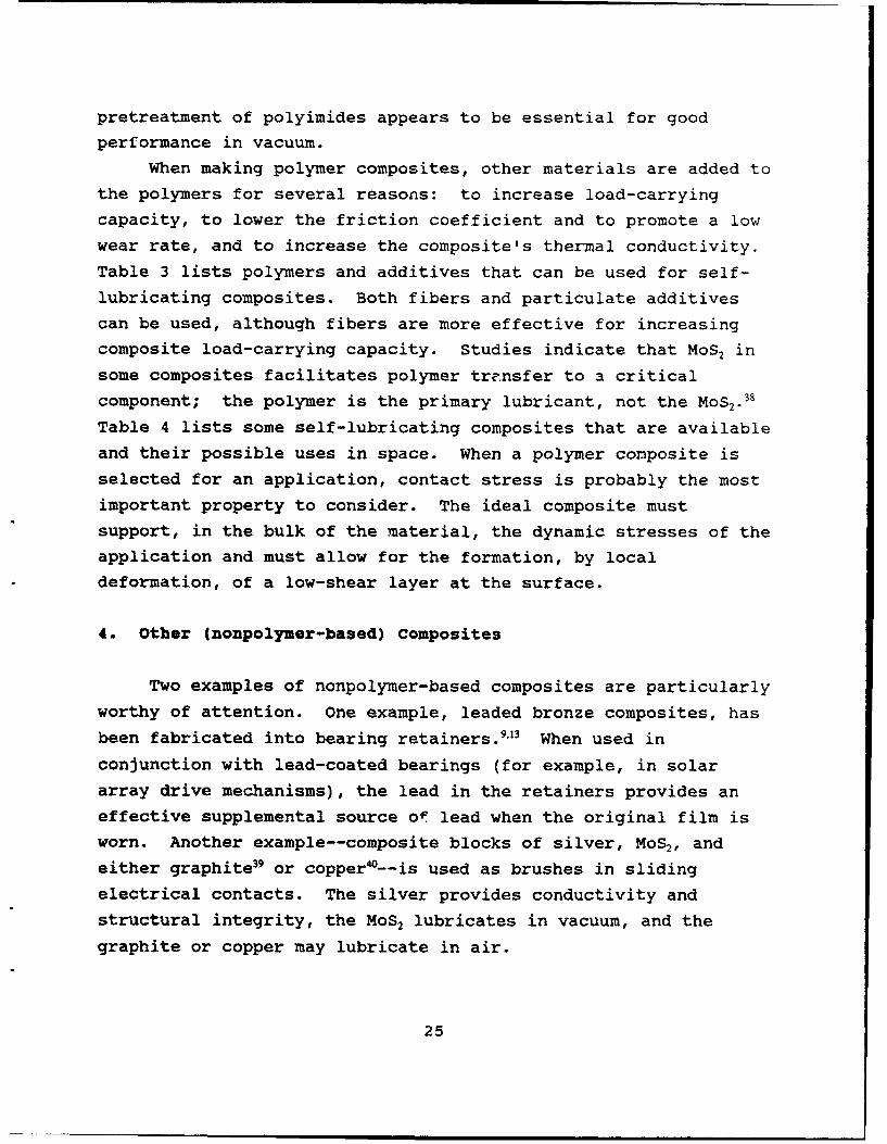
pretreatment of polyimides appears to be essential for good
performance in vacuum.
When making polymer composites, other materials are added to
the polymers for several reasons: to increase load-carryingcapacity, to lower the friction coefficient and to promote a low
wear rate, and to increase the composite's thermal conductivity.
Table 3 lists polymers and additives that can be used for self-
lubricating composites. Both fibers and particulate additivescan be used, although fibers are more effective for increasingcomposite load-carrying capacity. Studies indicate that MoS, in
some composites facilitates polymer transfer to a critical
component; the polymer is the primary lubricant, not the MoS 2 .38
Table 4 lists some self-lubricating composites that are availableand their possible uses in space. When a polymer composite is
selected for an application, contact stress is probably the most
important property to consider. The ideal composite mustsupport, in the bulk of the material, the dynamic stresses of the
application and must allow for the formation, by localdeformation, of a low-shear layer at the surface.
4. Other (nonpolymer-based) Composites
Two examples of nonpolymer-based composites are particularly
worthy of attention. One example, leaded bronze composites, has
been fabricated into bearing retainers. 9,13 When used inconjunction with lead-coated bearings (for example, in solar
array drive mechanisms), the lead in the retainers provides aneffective supplemental source of lead when the original film is
worn. Another example--composite blocks of silver, MoS2, and
either graphite39 or copper•--is used as brushes in slidingelectrical contacts. The silver provides conductivity and
structural integrity, the MoS 2 lubricates in vacuum, and the
graphite or copper may lubricate in air.
25

Table 3 Plastics and Fillers for Self-Lubricatiri Coxp'ositc
MaxiMum UscfulMaterial 11!1mperaturv- (()
ThermoplasticsPolyethylene (high MW and UHMW) 810Polyacetal (homo- and co-polymer) 125Nylons (types 6, 6.6, 11) 130Poly (phenylene sulphide) -2,)Poly (tetrafluoroethylene) 275Poly (p-oxybenzoate) 3W)
ThermosettingPhenolics -150Cresylics - 150Epoxies - 2WSilicones - 250Polyimides -
ReinforcementsGlass fibersAsbestos fibersTextiles (polyester, "Nomex,'" cotton)Mica
Friction and Wear Reducing AdditivesGraphiteMolydenum disulphidePolytetrafluoroethylene (PTFE)Metal oxidesSilicone fluids
Thermal Conductivity AdjunctivesBronzeGraphiteSilver
26
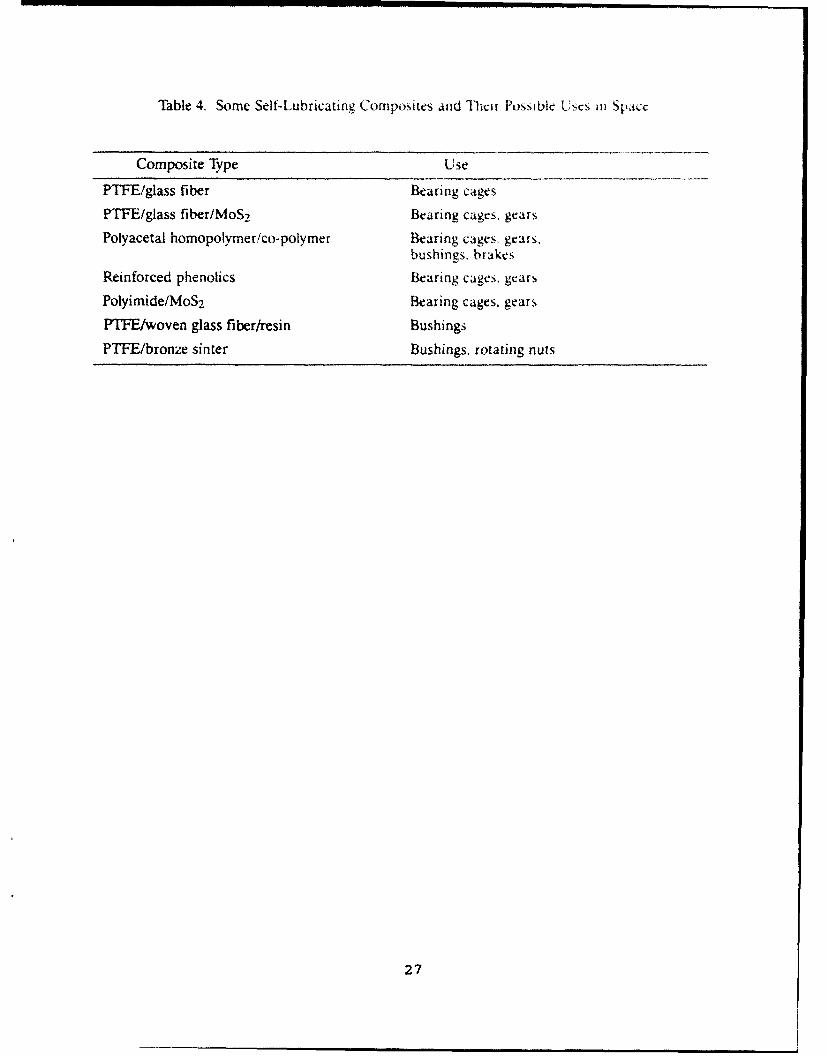
Table 4. Some Self-Lubricating Composites and lbeir Possible tfscs 1n Space
Composite Type Use
PTFE/glass fiber Bearing cages
PTFE/glass fiber/MoS 2 Bearing cages, gears
Polyacetal homopolymer/co-polymer Bearing cages, gears,bushings, brakes
Reinforced phenolics Bearing cages. gears
Polyimide/MoS 2 Bearing cages. gears
PTFE/woven glass fiber/resin Bushings
PTFE/bronze sinter Bushings. rotating nuts
27

B. LIQUID LUBRICANTS
Examination of Table 2 would suggest that the merits of solid
lubricants frequently exceed those of liquid lubricants in vacuum
applications. However, liquid lubricants are often used in spaceapplications, particularly on U.S. systems. In the early years
of the space program, liquid lubricants were understood better
than solid lubricants, so mechanisms were engineered to make low
vapor pressure liquids work in vacuum applications.""' Early
success with liquids slowed the incorporation of solid lubricants
into U.S. space systems. In contrast, European-designed space
systems have often incorporated solid lubricant technology as ithas evolved. 42 The primary advantage of liquid lubricants over
solid lubricants is their long life in high-cycle applications,
such as in gyroscopes. Long life results because liquid
lubricants can be resupplied and they have low frictional noise
in bearing applications. Another advantage is that liquid
lubricants have high thermal conductance, which may assist inmanaging thermal stability on spacecraft. For terrestrial vacuum
systems, however, these advantages often do not outweigh the
disadvantage of potential contamination from fluids. Therefore,
in terrestrial vacuum systems, the use of modified surfaces
and/or lubrication by solids or greases is the preferred approachfor manipulators and other mechanisms.
A particular disadvantage of liquid lubricants for spaceapplications is that accelerated testing, while desirable, is
difficult because of the synergistic dependence of lubricant
properties, such as film thickness, on operational parameters,
such as contact speed, load, and temperature. It is reasonable
to compare the performances of two or more different fluid
lubricants in tests in which operational conditions are
intentionally more severe than for the expected application. But
extreme care is required in the selection of the parameters to be"accelerated", and specific acceleration factors should never be
28
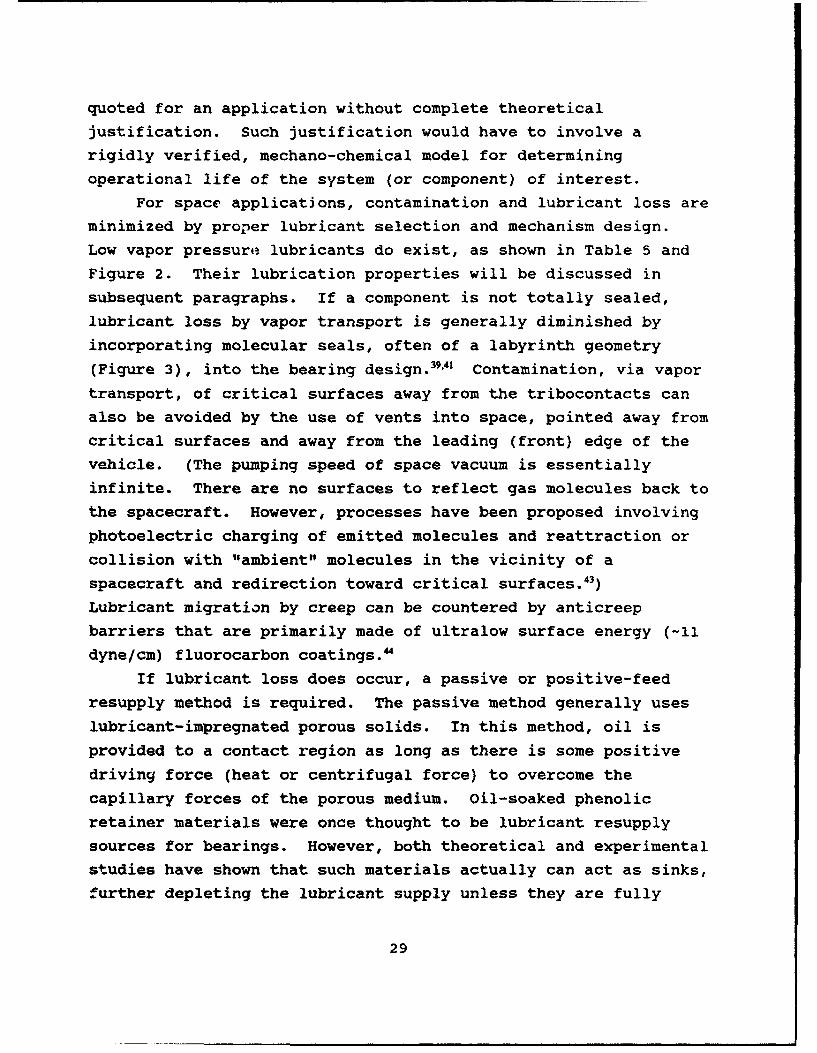
quoted for an application without complete theoretical
justification. Such justification would have to involve a
rigidly verified, mechano-chemical model for determining
operational life of the system (or component) of interest.
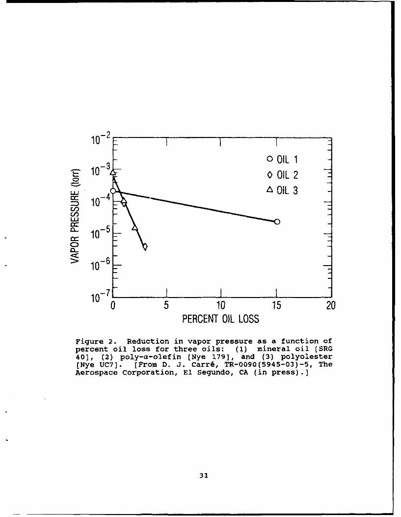
For space applications, contamination and lubricant loss are
minimized by proper lubricant selection and mechanism design.
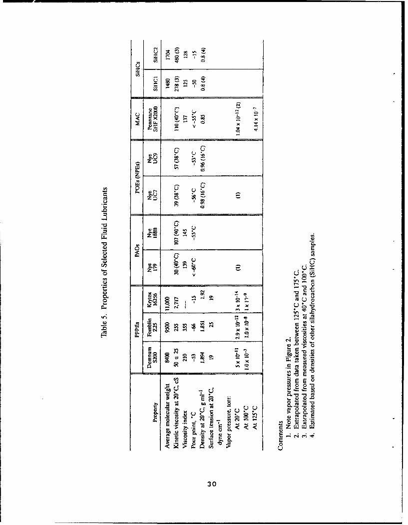
Low vapor pressure lubricants do exist, as shown in Table 5 and
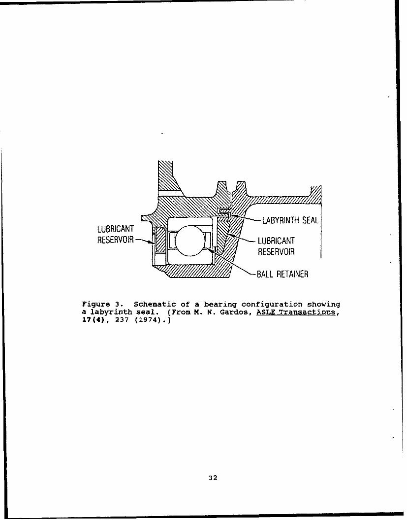
Figure 2. Their lubrication properties will be discussed insubsequent paragraphs. If a component is not totally sealed,
lubricant loss by vapor transport is generally diminished by
incorporating molecular seals, often of a labyrinth geometry
(Figure 3), into the bearing design.39'41 Contamination, via vapor
transport, of critical surfaces away from the tribocontacts canalso be avoided by the use of vents into space, pointed away from
critical surfaces and away from the leading (front) edge of the
vehicle. (The pumping speed of space vacuum is essentially
infinite. There are no surfaces to reflect gas molecules back to
the spacecraft. However, processes have been proposed involving
photoelectric charging of emitted molecules and reattraction orcollision with "ambient" molecules in the vicinity of a
spacecraft and redirection toward critical surfaces.' 3 )
Lubricant migration by creep can be countered by anticreep
barriers that are primarily made of ultralow surface energy (-11
dyne/cm) fluorocarbon coatings."
If lubricant loss does occur, a passive or positive-feed
resupply method is required. The passive method generally uses
lubricant-impregnated porous solids. In this method, oil isprovided to a contact region as long as there is some positive
driving force (heat or centrifugal force) to overcome the
capillary forces of the porous medium. Oil-soaked phenolic
retainer materials were once thought to be lubricant resupplysources for bearings. However, both theoretical and experimentalstudies have shown that such materials actually can act as sinks,
further depleting the lubricant supply unless they are fully
29
r-~
eq.
v1 0 0
4) CZ ~ I
C.
Cl
-o CI
CT7
I l V3
*00
C4.1
C. E1 EoI. -3
4) CL
- -44 i ei 4
- If.' - .n
30~ .
10-2 I
0 OIL 1£ 10 OIL 2_0
109C,,
Cr
05
10.: 10- 6 _7
10-7 J ___
0 5 10 15 20
PERCENT OIL LOSS
Figure 2. Reduction in vapor pressure as a function ofpercent oil loss for three oils: (1) mineral oil [SRG40), (2) poly-a-olefin [Nye 179), and (3) polyolester[Nye UC7]. [From D. J. Carrf, TR-0090(5945-03)-5, TheAerospace Corporation, El Segundo, CA (in press).]
31
LUBRIANT •• • - -•LABYRINTH SEAL
LUBRICANTR O RESERVOIR
S• BALL RETAINER
Figure 3. Schematic of a bearing configuration showinga labyrinth seal. (From m. N. Gardos, ASLE Transactions,17(4), 237 (1974).]
32
saturated with oil. 45'1 This saturation process can take up to
2 years at ambient temperature. 39' 4 7 Porous nylon-based
materials, polyimides, and copolymer foams of acrylonitrile have
been used as reseviors in several mechanisms, but they are
subject to the same potential problems as phenolic retainer
materials. The positive-feed method uses positive-feed suppliers
with centrifugal oilers or controlled pumps. This method has
been used for higher load (requiring larger bearing sizes) and/or
longer life mechanisms.
There are several types or categories of liquid lubricantsthat have been used or could be used for vacuum/space
applications. These categories include: (1) silicone oils; (2)
mineral oils; (3) perfluoropolyalkylethers (PFPEs); and (4)
other new synthetics (including poly-a-olephins [PAOs],
polyolesters [POEs], multiply-alkylated cyclopentanes (MACs], and
others). Except for gyroscope applications, these lubricants
generally encounter boundary contact conditions at least at some
time during their service life. Boundary lubrication additivesare available for many of these lubricants and will be reviewed
after lubricants are discussed.
1. Silicone Oils
The low vapor pressures and low pour points of some silicone
oils led to their early use in space applications. However,
these oils are only moderately effective lubricants. One problem
is that some of these oils tend to form polymers on the bearing
surface, which leads to torque noise. Another problem is that
these oils creep readily on metal surfaces. Because of these
problems and the availability of better alternatives, silicone
oils would not be used on contemporary spacecraft. However, these
oils are used as damper fluids and as thermal conduction media in
some instances.
33

2. Mineral Oils
Highly refined mineral oils have been a popular choice for
sealed mechanisms, such as momentum wheels, reaction wheels, and
despin mechanisms. Mineral oils from manufacturers, including
Shell Oil Company, Bray Products Division of Burmah Castrol Inc.,Nuodix Inc. of Texaco Chemicals, Royal Lubricants, and others
have been used successfully.' 0 Specific examples include those of
the Aeroshell and Apiezon series. (Another oil, developed by
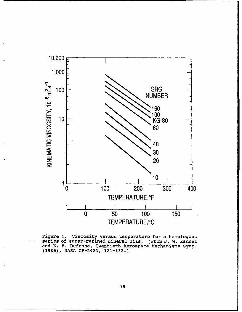
British Petroleum, BP 110, is no longer marketed.) A series ofsuper-refined gyroscope lubricants (SRG and KG-80 [Originally
manufactured by Kendall Oil Company and now available through W.
F. Nye Company]) is also available which comprises a homologous
group of natural polymers that allows the designer to choose a
fluid having particular viscosity characteristics for a specific
application (Figure 4)." Mineral oils also can be formulated
with antiwear and other additives.
3. Perfluoropolyalkylethers (PFPEs)
PFPE lubricants have lower vapor pressures, lower pourpoints, and higher viscosity indexes than mineral oils (see Table
5). Thus, they are useful in space mechanisms that are not
completely sealed or that are somewhat cooler (>200 K) than would
be acceptable for mineral oils. In particular, one of the PFPEs
(Fomblin Z25) has a very high viscosity index and is
exceptionally useful over a wide temperature range.
PFPEs perform reasonably well under nonboundary contact
conditions. However, these lubricants have definite limitations
when used for applications involving boundary contact,
particularly on steel surfaces (see Table 6). Conventionalantiwear additives do not dissolve into the PFPE fluids, althougha new class of compatible additives has been reported. 49 During
boundary contact in the absence of additives, fluorine from the
34
10,000
1,000 0
c'J 100 SRGE XNUMBER -T
1600 10 100
F5 10 KG-800 60
05 40Icc 30
W 20
10 10 200 101
0 10 00300 400TEMPERATURE,°F
0 50 100 150TEMPERATURE, 0C
Figure 4. Viscosity versus temperature for a homologousseries of super-refined mineral oils. (From J. W. Kanneland K. F. Dufrane, Twentieth Aerospace Mechanisms Symp.(1986), NASA CP-2423, 121-132.]
35
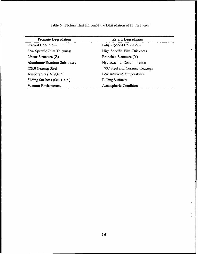
Table 6. Factors That Influence the Degradation of PFPE Fluids
Promote Degradation Retard Degradation
Starved Conditions Fully Flooded ConditionsLow Specific Film Thickness High Specific Film Thickness
Linear Structure (Z) Branched Structure (Y)Aluminum/Titanium Substrates Hydrocarbon Contamination
52100 Bearing Steel IOC Steel and Ceramic Coatings
Temperatures > 200"C Low Ambient Temperatures
Sliding Surfaces (Seals, etc.) Rolling SurfacesVacuum Environment Atmospheric Conditions
36

PFPE can react with iron to form FeF3, a catalyst for the further
breakdown of the polymer.5 More F is released, which sustains a
chain reaction. Lubricant degradation by polymerization leads to
high bearing torque noise and excessive wear. The substrate-
induced degradation can be retarded by substituting one or both
of the steel surfaces with either ceramic components or ceramic-
coated steel (or presumably by using the new additives). Tic-
and TiN-coated steel and Si 3N4 components have shown improved
performance, as will be discussed in the section on surface
modification.5'PFPEs have extremely low surface tensions (-18 dyne/cm) and,
therefore, creep very readily over metal and other surfaces.
Because of their similar chemical structures, the lubricants also
dissolve fluorocarbon coatings that are used as antimigration
barriers. The available commercial PFPEs and their properties
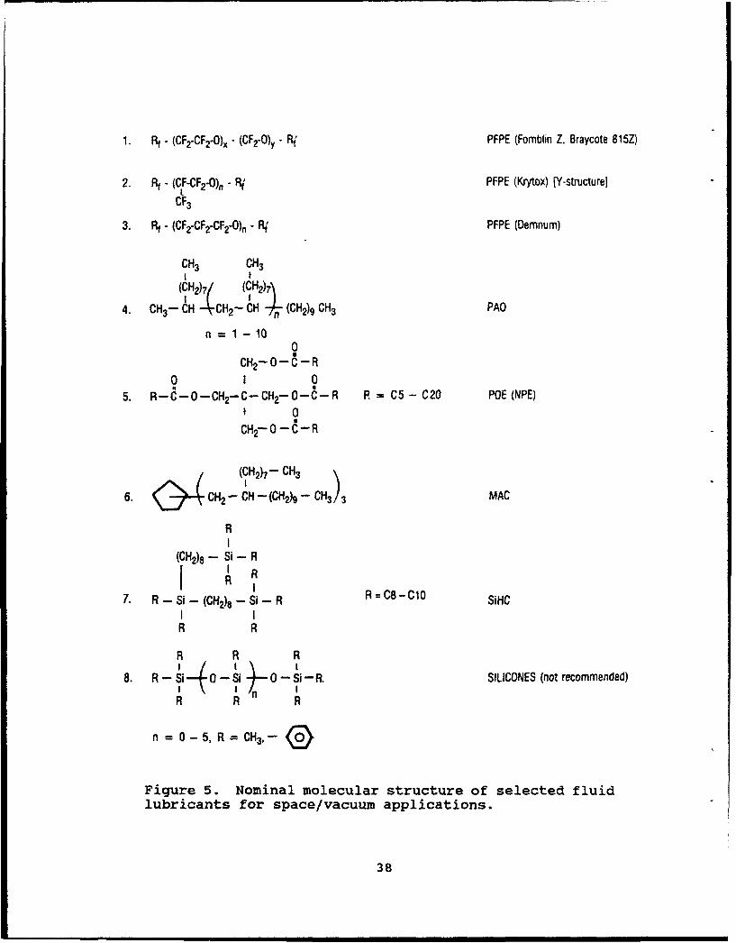
are listed in Table 5. Their molecular structures are shown in
Figure 5. The acetal groups present on the Fomblin Z25 or
Braycoat 815Z polymers are particularly reactive under boundary
conditions.
4. Other Synthetic Lubricants
Poly-e-olefin (PAO), polyolester (POE), multiply-alkylated
cyclopentane (MAC), and other hydrocarbon polymer (HP) oils can
be synthesized and blended to produce viscosity, vapor pressure,
pour point, and other properties in a controlled way that will
suit various needs.39, 52,53 Vapor pressures that are as low as
those of linear PFPEs have not been obtained for the PAOs and
POEs, but they can be lower than those of conventional mineral
oils. Vapor pressure studies of the MAC oils are currently
underway--extrapolations based on measurements at higher
temperatures (125-1750C) suggest that room temperature vapor
pressure of at least one MAC oil should be low, as listed inTable 5.4 Outgassing studies of selected PAOs and POEs
37
1. Rf - (CF2-CF2-O)x - (CF2-O)y - F PFPE (Fomblin Z, Braycote 815Z)
2. Rt - (CF-CF 2-0)n - Rj PFPE (Krytox) [Y-structurel
CF3
3. Rf - (CFZ-CF 2-CF2-O)n - R PFPE (Demnum)
CH3 CH3I I
(CH2h7 (CH) 7
4. CH3- CH -- CH2- CH n (CH2)9 CH3 PAO
ni= 1 -10
0CH2 -0---R
0 I 05. R-C-0-CH2-C-CH 2-O-C-R R = C5 - C20 POE (NPE)
I 0
CHr- - C- R
(kH2)7- CH3
6. CH2 - CH- (CH2)9 -CH33 MAC
RI
(CH2)8 - Si - RI ' RI R 8 - 1
7. R - Si - (CH2)8 -- Si - R R=C8-C10 SiHCI IR R
R R R
8. R - Si 0 - Si 0 - Si-R. SILICONES (not recommended)
R R n R
n = 0-5, R =CH3,--Q
Figure 5. Nominal molecular structure of selected fluidlubricants for space/vacuum applications.
38
(specifically a neopentyl ester [NPE]) show that removal of
relatively high-vapor-pressure light fractions, which account for
S3% of the as-received lubricant, reduces the vapor pressure byseveral orders of magnitude without affecting viscosity at room
temperature (see Figure 2).'
These synthetic hydrocarbons can be blended with
conventional additive packages to provide the same type of
protection against wear, oxidation, and corrosion as achieved bynatural hydrocarbons. However, for vacuum applications, the lowvapor pressures of the base stocks make the additives the most
volatile constituents of blended lubricants. Therefore, newadditives are being developed that will be compatible with the
base stocks and that will have the desired low volatilities.Laboratory screening tests have shown that synthetic hydrocarbons
give the longest wear lifetimes in a simulated boundary-
lubrication test facility. Bearing tests with a fixture designedto simulate the oscillatory motion of a weather scanner have
shown that a PAO provides near freezing (0 0 C) temperature
capability and significantly outlasts both a silicone oil and a
PFPE (Figure 6) .52s5 PAO oils have given very good performance
in lightly loaded, high speed gyroscope bearings. Tests are
presently aimed at determining the utility of these synthetic
oils in more demanding applications, such as in the spin bearings
of momentum and reaction wheels.
Another, relatively new class of synthetic lubricants withvapor pressures acceptable for vacuum applications and the
capability to be compounded with additives is known by the term"Itsilahydrocarbons.'' 6 Their tribological performance has not been
thoroughly tested in specific applications, but the results of
conventional four-ball and traction tests are very encouraging.16
39

BOUNDARY LUBRICANT OSCILLATORY SCANNER
SCREENING TEST BEARINGS
Mn.uni SILICONE AFTER 1800 hrs
50% 1K'REASE
I01JA• REVS
lOXI PFPE AFTER 2300 hrs
PAO AFTER 4300 hrs
Figure 6. Life-test results for various lubricantsinvestigated with a boundary lubricant screening test(left) and oscillatory scanner-bearing test (right).Silicone arnd PFPE failed after the indicated times, whilethe PAO test is still running. (From P. D. Fleaschauerand H. R. Hilton, Mat. Re s. s_0c. Symp. Proc-, 140, 9( 1989 ) .)
40

5. Additives
Liquid lubricants are formulated with additive packages in
order to provide, for example, low friction and antiwear
protection in elastohydrodynamic (EHD) or extreme pressureconditions, and to retard lubricant oxidation or substrate
corrosion during atmospheric storage. Most of these additives
were developed for use under atmospheric conditions, with oxygenand water vapor, and were compounded with base stocks on a highly
empirical basis. In vacuum, once water vapor and reactive gases
are removed, it is doubtful that most additives work in an
identical chemical-mechanistic manner as they operate at
atmospheric pressures. Furthermore, the nature of the
interactions of these additives--that were developed for steelsubstrate surfaces--with newly emerging ceramic cLmponents (e.g.,
SiC,, Si 3N4 , TiC, TiN) is unknown. Additive surface chemistry iscurrently an active topic of study by many tribologists and
surface scientists.
Antiwear or extreme pressure (EP) additives are often
required when liquid lubricants are used in mixed or boundary
regime applications in vacuum. Numerous examples exist where
antiwear additives, such as tricresol phosphate, improve the
operation of bearings and provide longer life. In boundary-
lubrication situations, the modern designer must carefullyconsider the relative merits of liquid and solid lubricants.
Liquid lubricants have long life and low torque but require
additives and possibly, reservoirs and molecular vapor sealr inthe design; solid lubricants operate well in boundary conditions
without reservoirs or seals but have a finite life. Another
option, surface modification, is also worthy of consideration.
Common EP additives include naphthenates of lead and other metalsand dialkyldithiophosphates of zinc or antimony.
The role of anti-oxidation additives in vacuum lubricants isto prevent degradation of lubricants during storage. Common
41
types of such additives include hindered phenols, and amines,
such as polyphenyl a-napthylamine.Antirust additives can be particularly important for
c-mponents stored in air that are coated with the PFPE oils,
because these oils do not offer the same oxidation protection to
the substrate as do other oils. Unfortunately, common antirust
additives do not dissolve in the fluorocarbons any better thanantiwear materials. For one of the PFPE greases (see next
section), NaNO2 is added by first being adsorbed onto bentonite
clay and then being suspended, together with the clay, to form
the grease.
C. GREASE LUBRICANTS
Greases are comprised of oils compounded with a pore-network-forming thickener, such as a soap or a fine particlesuspension. For thorough descriptions of greases and their
properties, the reader is referred to literature references. 57,S8
For results of an extensive testing program of greases in vacuum,
see the reference written by McMurtrey. 5 9 A very brief overview
of grease lubricants is provided here for reader convenience.
Depending on the type of oil and the nature of thethickener, greases can be formulated for various applications
involving a variety of components with different types of contact(e.g., slow or high speed angular contact ball bearings,
journals, gears). Oils in greases can be from any of the
categories discussed in previous sections. However, the
solubility properties (i-e., chemical compatibility) of the oilwill determine the selection of thickener and, hence, the grease
properties. Mineral oils and certain synthetics have good solvent
prioperties, so they can be formulated with soaps of different
cations to make what are known as channeling greases. Suchgreases are pushed out of the way and form a path (channel) when
the balls of a bearing pass through the grease. When working
42
properly, oil will continually diffuse out of the mounds of
grease on the edges of the ball path to supply lubricant to the
contacting surfaces. If a grease is fluid enough that it tends
to fill the spaces between balls, it is a "slumping" (non-
channeling) grease. The consistency of a grease depends on the
type of thickener used and the relative amounts of oil vs
thickener.
PAO and PFPE oils are poor solvents for soaps, so greases of
these oils are made by suspending fine particles of inert
materials in the oils until their consistency becomes thick like
a grease. Two common thickeners of this type are Cab-o-sil
(finely ground amorphous silica) by Cabot Corporation and another
powder that is simply designated as a fluorocarbon telomer by
Burmah-Castrol. This manufacturer also produces widely used PFPE
greases, Braycoat 600, 601 (also contains a rust inhibitor), and
602 (also contains MoS 2). One drawback to this type of grease is
that the thickener can get into the ball path of a precision
bearing and, being solid, can cause noisy operation.
The primary purpose for using grease in a vacuum application
is that the grease can act as a reservoir for supplying oil to
contacting surfaces. A bearing properly packed with grease will
also suffer less oil loss by creep or physical spattering because
of the physical barrier the grease can provide. However, the
lubrication properties of any grease can be only as good as those
of the base oil, so care must be exercised in selection of the
base oil. For example, formulation of a volatile oil into a
grease cannot prevent the oil from contaminating a vacuum system;
a low volatility oil must be used.
D. SURPACE MODIFICATION WITH AND WITHOUT LUBRICATION
The fourth approach for providing low friction and limited
wear in vacuum is to use no lubricant all. Instead, the low
reactivity of the substrate surface can be relied upon to prevent
43
cold-welding. For lightly loaded applications that have low duty
cycles, this option can work very well. For mechanisms interrestrial vacuum systems, this approach is often a temptingfirst choice. Then if the component fails to operate properly,
vacuum can be broken and a lubricant can be applied and tested
for the application. On the contrary, spacecraft-mechanism
performance cannot be left to chance, and most mechanisms that
experience more than light loads and/or have frequent use will
require tribological modification in the contact zone. The
modification approaches in this section do not have the same
historical degree of proven success as the lubricants mentioned
in the previous sections; the modifications are simply too new.
Nonetheless, the authors believe that these emerging technologieswill be used increasingly in the future, either alone or in
conjunction with lubricants.Since metals generally do not have unreactive surfaces once
their passive layers are worn away, chemical modification of thesurface region or complete materials substitution is required.
The basic idea is to avoid metal-to-metal contact that mightcause cold-welding or adhesive wear. Ceramics often are
covalently bonded materials and generally have a lower reactivity
than metals (one exceptionally inert metal being gold). Inparticular, the carbides and nitrides of silicon and titanium
(SIC, Si 3N4 , TiC, TiN) have excellent attributes: they are hard
(resist plastic deformation), chemically inert (resist cold-
welding/adhesive wear), and have high melting temperatures
(resist chemical interdiffusion between contacting surfaces).
They are also commercially available, either as ceramic
components or as ceramic coatings on bearing steels. A possible
alternative is to ion implant C, N, or metals into steel surfacestd create a hard, unreactive surface region. Studies have shown
that ion implantation can improve the corrosion and wear
resistance of steel operating in ambient environments.6 Data of
performance in vacuum applications is needed. Another future
44

alternative may be polycrystalline diamond coatings. However,
although hard carbon films are used for some computer disk drive
applications, diamond films cannot yet be applied to metals
without overtempering and distortions, and their tribological
properties still need extensive investigation.
TiC coatings formed by chemical vapor deposition (CVD) onto
steel have been used for over a decade in the tool industry to
prolong tool life. CVD Tic coatings are also commercially
available on 440C balls for bearing applications. 61 The high
temperatures (>10000C) used in the CVD process, in which TiC1 4,
and H2 and N2 gases react on the hot steel substrate to form TiC,
soften the steel. Consequently, the balls have to be heat
treated again to regain hardness after deposition, and
anisotropic phase transformations during the second heat
treatment distort the balls into egg-shaped structures. The
balls are then repolished to regain sphericity. Balls are
available with a 0.375 inch diameter or less. Larger sizes
distort to tolerances greater than the allowable coating
thickness, resulting in "bald spots" after polishing. TiC-coated
balls have been used without additional lubricant in the primary
deployment mechanism of the Space Telescope solar array. These
balls have also been used with PFPE oil (Fomblin Z25) for the
Spacelab Instrument Pointing System. 6 2
TiN and TiC coatings produced by sputtering also have been
used for years in the tool industry. The lower operating
temperatures of the sputtering process, particularly some high-
rzte variations, 63',6 can, in principle, avoid the second heat
treatment problems associated with CVD. There have been very
limited studies of sputtered TiN in bearing or gear applications
in vacuum. Eccentric bearing tests in vacuum showed an order of
za-gnitude increase in life when TiN-coated components were
compared to uncoated 440C steel. In both cases, the bearings
were lubricated with a PFPE oil (Krytox). A
45

Solid ceramic parts, such as Si 3N4 balls formed by hot
isostatic pressing, are commercially available with diameters up
to 2.5 inch.6 5 Appropriate polishing can produce balls down to
Grade 3 finish. Grades 3, 5, and 10 are usually produced. Such
balls have been used in hybrid bearings (ceramic balls and steel
races) operated in ultrahigh-vacuum, either unlubricated or with
solid or liquid lubricants. Eccentric bearing tests of PFPE-
lubricated hybrid bearings in vacuum (Si 3N4 balls against 440Csteel races) again showed an order of magnitude increase in life
over an all-steel configuration. The gains observed with the
Si 3N4 /steel hybrid were identical, within experimental error, to
gains obtained with all TiN-coated components. 51 The results
emphasize the improvements that can be obtained when metal-to-
metal contact is avoided, even by the elimination of only one
metal surface from the contact. When used with PFPE oils, the
ceramics appear to retard chemical degradation of the lubricant
by Fe in the steel substrate.
Although the tribological improvements of using bulk
ceramics or ceramic coatings on steel appear similar--basically
because metal-to-metal contact is eliminated--there are important
differences in bulk properties that must be considered. The
ceramic coatings are thin enough (<3 Am) that the majority of the
load is carried by the steel substrate. Therefore, the modulus
of the steel determines the stress levels generated. Si 3N4 has a
Young's modulus (310 GPa or 45 x 103 Ksi) that is 50% higher than
that of steel. Thus, higher contact stresses are generated inthe ceramic than in the steel at any particular load. In
addition, the thermal coefficient of expansion (3.5 x 10Q) and
the Poisson's ratio (0.28) must be taken into account when
ceramics are combined with steel races in a given application.
Tighter race conformance to the ball relative to steel bearingsis sometimes required to reduce stresses, but the result can be
increasing operating friction or torque.
46

A potential alternative to coatings or bulk ceramics is ion
implantation of steel surfaces. •616S Energetic (100 KeV) ion
beams of various species (e.g., B, C, N, Ti) are directed towards
the substrate. Such species can form compounds in the near-
surface region (<0.4 Mm) or simply disrupt the surface structure
(render amorphous) so that wear resistance can increase. This
approach does not change the dimensions of the component.
Sometimes, substrate cooling is necessary when high flux beams
are used. The process, as originally developed, was line-of-
sight, but isotropic plasma implantation techniques have become
available. 69 Ion implantation has been used in many different
terrestrial applications. In a vacuum application, ion
implantation is being tested for possible use in the main-engine
bearings of the space shuttle to provide improved corrosion and
wear resistance. (During use, these bearings get very hot so
that lubricants do not survive; also, stored bearings rust in
condensed moisture.) A terrestrial bearing study of balls made
of TiC-coated 440C, of Si 3N4 , or of ion-implanted (Ti, C) 52100
showed comparable improvements in performance for each modified
material over 52100 balls in fretting tests.7 ° In gyroscope spin
tests, the implanted balls showed slight evidence of wear
relative to the ceramic or ceramic-coated balls, but all three
types performed better than the standard 52100 balls.
47
IV. SPECIFIC APPLICATIONS
A. SPACE ENVIRONMENTS
Although the functions or missions of different spacecraft
systems vary widely, there are many similarities in their
mechanical requirements. There is a large body of literature on
the design and applications experience of spacecraft mechanisms,
including discussion of tribology issues.7 1 Table 7 is a list of
mechanical components often found on spacecraft and is arranged
according to the type of mechanical contact. The list is not
meant to be exhaustive but is typical of components that have
exhibited specific problems.n Articles in a recent volume of
Tribology International 73 are all devoted to various aspects of
tribology of space systems throughout the world. Each country's
space program is treated individually, and there are some general
articles on different technologies.
It is important for the reader to understand that the field
of space tribology is undergoing major advances in lubricant
technology. Such advances are being driven by two trends: (1)
the required lifetimes of spacecraft are increasing, making some
of the past lubricant practices inadequate; and (2) mechanical
component failures are starting to become the life-limiting
systems on spacecraft, because the traditional failure points
(power systems, electronics, and contamination problems) are
using newer technologies that exceed the lifetimes of the
tribosystems.' 4 3 The tribology advances include new or improved
tribomaterials and the generation of more extensive test data to
qualify these tribomaterials for various applications. Table 7
is a list of materials technologies either in use or available
for implementation on various spacecraft components. The
different symbols in the table correspond to a critical or less
stringent requirement or to a preferred or alternative
49
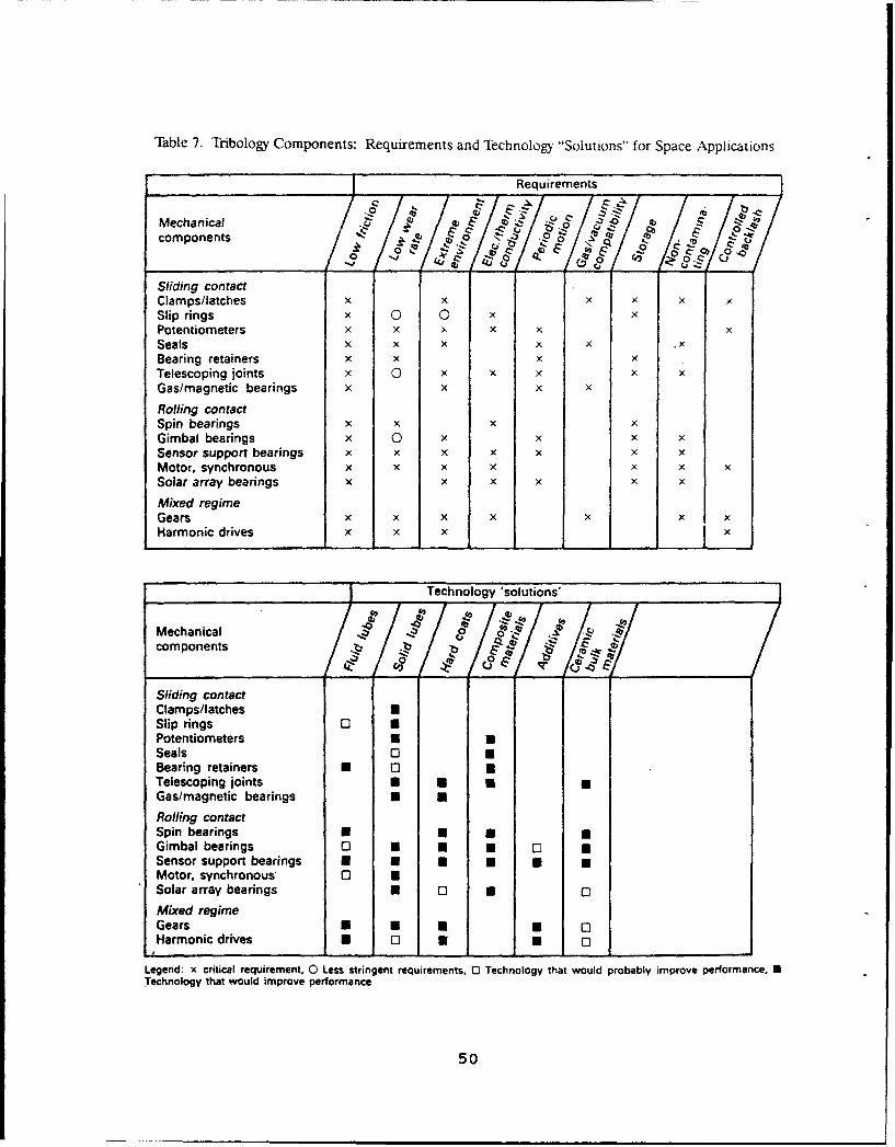
Table 7. Tribology Components: Requirements and Technology "Solutions" for Space Applications
Requirements
Mechanical 4b~? ~ --
components b , 01"______ ,.9,4 o 'l • /9&C...
Sliding contactClamps/latches x x x X XSlip rings x 0 0Potentiometers x X x x x xSeals x x x x .xBearing retainers x X xTelescoping joints x ( X x xGas/magnetic bearings X x x X
Rolling contactSpin bearings x x ×Gimbal bearings x 0 x X ×Sensor support bearings X x x x x x xMotor, synchronous x x x x x xSolar array bearings x x x x x X
Mixed regimeGears X X X X X X xHarmonic drives X X - X
Technology 'solutions'
Mechanical .f , "components _ /
I• /•
Sliding contactClamps/latches USlip rings 0 3Potentiometers a ESeals 0 0Bearing retainers N 03 0Telescoping joints U a 0Gas/magnetic bearings N aRolling contactSpin bearings • U a EGimbal bearings 0 * N * "Sensor support bearings U N a * WMotor, synchronous' 0 USolar array bearings • 0 • 0
Mixed regimeGears U N • -Harmonic drives N 0 U U Q
Legend: x critical requirement. 0 Less stringent requirements. 0 Technology that would probably improve performance, UTechnology that would improve performance
50

technology. The reader is referred to the references for more
details concerning vacuum applications.
B. TERRESTRIAL UHV ENVIRONMENTS
UHV chambers are used primarily by three groups of people:
(1) surface scientists conducting chemical experiments oranalytical measurements (such as spectroscopy, diffraction, ormicroscopy), or both, on the first few atomic surface layers of
materials; (2) scientists and engineers synthesizing orfabricating materials with features or structures of micrometer
to nanometer scale; and (3) engineers testing hardware intended
for vacuum applications. All three groups require extremelyclean, stable environments to obtain reproducible results.
Contamination from lubricants in the form of vapors, migrating
liquid lubricant molecules, or particulate debris is notacceptable. Designers try, as much as possible, to keep
mechanical components of such systems external to the vacuum and
rely on feed-throughs, magnetic couplings, or bellows to transmit
or facilitate component motion. However, UHV systems often
contain manipulators to move materials within the chamber orbetween chambers. Rotatable fixtures are also required in line-
of-sight deposition processes to adequately expose nonplanarsubstrates to the deposition flux. If the manipulators are used
frequently, undergo moderate to heavy stresses, or have tight-
tolerance components, some lubrication is generally required to
avoid frequent mechanism repair (which necessitates breaking
vacuum). Lubricants for pumps are not covered in this report
because that technology is well developed, and the pump
manufacturers are quite capable and flexible in meeting customer
requirements for specific applications.
The general strategy that has been used is to avoid metal-to-metal contact and to have minimum lubrication. For example,PTFE and polyimide polymers (pure or composites) have been used
51

to make bearing bushings for UHV manipulators. Recently, Si 3N4
balls have been used to make hybrid bearings for UHV mechanisms.
(Presumably TiC- or TiN-coated materials would also work.) The
Si 3N4 has been used without lubricant or with spray-deposited WS2(Dichronite) for more demanding applications. 74 WS2 has also
been used on steel. Sputter-deposited MoS 2 has been used on
deposition fixtures and on a cryogenic (helium) manipulator foran acoustic microscope (made of steel), resulting in lower
operating torque of these mechanisms.
Grease (Castrol [Braycoat] 600) has also been used in a
"robot" manipulator operated in a molecular beam epitaxy (MBE)
system. 75 The MBE robot has many gears, bearings, and lead
screws. Over 20 robots have been built, and some have operated
over 5 years without maintenance. The grease was selected
instead of solid lubricants, in part, because of a desire to
avoid particulate generation. Micrometer-sized particles have
unusual migration tendencies in vacuum (they are easily propelled
by electrostatic charges) and are devastating to the fabrication
of submicrometer devices. The particulate generation properties
of solid lubricants as a function of film properties (for
example, porosity) have not been systematically studied. Further
work is needed and is in progress.7 6 The designer should place
mechanisms below critical surfaces in vacuum, so that gravity
will move away debris from the sites of inevitable wear.
Containment barriers should also be considered that are
interposed in the line of sight between critical surfaces and the
lubricated sections of mechanisms.
Greases (e.g., Castrol Braycoat 600) are also used to
lubricate Viton seals between UHV and air on sliding
manipulators. Such seals are usually in multiple series, with
differential pumping between each seal.
When selecting tribomaterials, the designer should review
their temperature stabilities, load-bearing capabilities,
moisture sensitivities, and achievable tolerances. Obviously,
52
the vapor pressure of the tribomaterial must be below desired
system operating pressure. Since UHV systems are routinely bakedout, the vapor pressure and load-carrying capacities of the
tribomaterials must not degrade by such heating. Moisture
sensitivity is important if the mechanism is routinely storedand/or operated in air. Polyimides are extremely sensitive to
water vapor (these polymers absorb as much as 2% moisture andminutes or hours of moisture exposure will require subsequent
bake-out), while PTFE is not, yet polyimides have load-bearingcapabilities superior to those of PTFE. MoS2 is more sensitive
to water vapor exposure than WS2 (MoS 2 will significantly oxidize
over a period of months to a year), yet MoS 2 has better sliding
wear endurance in vacuum. (MoS2 oxidation can be effectively
avoided at atmospheric pressure by storage of the lubricated
component in a dry or inert gas, desiccated environment.)Sputter deposition can yield solid lubricant coatings to better
tolerance than burnishing or spray methods. Sputter-depositedfilms can also be prepared that will resist oxidation upon
standing (not operating) in air for many months, and such films
should be considered for conventional uses. Bonded films, thoughsubject to greater debris formation, are generally much more
resistant to oxidation. A typical procedure for applying bonded
films is to run the film in (burnish) after the normal
application and then remove any debris (with a vacuum brush)
before using.
53
V. SUMMARY
When selecting a lubricant for use in vacuum, the spacecraft
or vacuum system designer has many more options available today
than were available 30 years ago. Lubricants selected in thatera have been used until proven completely inadequate with regardto newer, more demanding system requirements. Changes have not
necessarily been made when better alternatives to the original
choices become available. All potential lubricant candidates
that can meet various system requirements should be considered in
the design phase. The lubricant(s) ultimately chosen for the
system should optimally address all system requirements in
proportion to the importance of the requirements. The tendency
to pre-select one lubricant based on its superior performance insatisfying one aspect of the system requirements should beavoided. In accordance with concurrent engineering principles,
tribology should be given sufficient and timely consideration
early in the vacuum/spacecraft system design phase, prior to
component fabrication. Such early attention can avoid the
conversion of an expensively fabricated mechanism into scrapmaterial, which increases system cost and causes delays in
schedule (which are also costly).
55

REFERENCES
I. H. M. Briscoe, Tribol. Int., 23(2), 67 (1990).
2. D. R. Peplinski, G. S. Arnold, and E. N. Borson, "Introduction to:Simulation of Upper Oxygen Satellite Exposure to Atomic Oxygen in Low EarthOrbit," 13th Space Simulation Conference (8-11 Oct. 1984, Orlando, FL), NASAConference Publication 2340 (1984), 133-145.
3.a. H. E. Sliney, J. Vac. Sci. Technol. A, 4, 2629 (1986).b. C. DellaCorte and H. E. Sliney, ASLE Trans., 30, 77 (1987).
4. I. L. Singer, Mat. Res. Soc. Svmp. Proc., 140, 215 (1989), and referencestherein.
5. D. J. Carrt, A Model to Describe Oil Loss Under Vacuum Conditions, TR-0090(5945-03), The Aerospace Corporation, El Segundo, CA (in press).
6. a. C. Taborski and C. E. Snyder, Jr., Silahydrocarbons: I. Synthesis andPronerties of a Class of Thermally Stable Fluids, AFWAL-TR-80-4072, WrightAeronautical Laboratories, Dayton, OH (Nov. 1980).
b. S. K. Sharma, C. E. Snyder, Jr., and L. J. Gschwender, Idustrial andEnaineering Chemistry Research, 29, 1858 (1990).
7. K. Miyoshi and D. H. Buckley, ASLE Transactions, 27(l), 15 (1983).
8 F. P. Bowden and D. Tabor, The Friction and Lubrication of Solids,Clarendon Press, Oxford (1958).
9. E. W. Roberts, Thin Solid Films, 181, 461 (1989).
10. E. L. McMurtrey, Lubrication Handbook for the Soace Industry--Part A:Solid Lubricants; Part 8: Liquid Lubricants, NASA TM-86556, NASA George C.Marshall Space Flight Center, Huntsville, AL (Dec. 1985).
11. Guiness Book of World Records, Bantam, New York (1988), p. 182.
12. M. N. Gardos, Tribol. Trans., 31(2), 214 (1988).
13. E. W. Roberts, Tribol. Int., 23(2), 95 (1990).
14. W. E. Jamison, Proceedings of the Third International Conference on SolidLubrication, ASLE SP-14 (7-10 August 1984), STLE, Park Ridge, IL (1984), p.73.
15.a. T. Spalvins, ASLE Trans., 14, 267 (1971).b. Ibid., 17, 1 (1973).
k6-.;- See, for example, articles in New Materials Approaches to Tribology:Theory and Aprilications, L. E. Pope, L. L. Fehrenbacher, W. 0. Winer, eds.,Mat. Res. Soc. Sym . rroc., 140, 215-284 (1989).
17. See, for example, articles appearing in Xhin Solid Films: 154, 309-332(1987); 181, 461-495 (1989); and in Surface and Coatinqs Technol., 36, 329-359 (1988); 43/44, 629-622 (1990).
57
18. M. R. Hilton, R. Bauer, and P. D. Fleischauer, Thin Solid F _Ens, 188, 219
(1990), and references therein.
19. V. Buck, Thin Solid Films, 139, 157 (1986).
20. M. R. Hilton and P. D. Fleischauer, Mat. Res. Soc. Symp. Proc., 140, 227(1989).
21. J.-Ph. Nabot, A. Aubert, R. Gillet, and Ph. Renaux, Surface and CoatingsTechnology, 43/44, 629 (1990).
22. C. Muller, C. Menoud, M. Maillat, and H. E. Hintermann, Surf. Coat.Technol., 36(1-2), 351 (1988).
23. H. Kuwano and K. Nagai, J. Vac. Sci. Technol A, 4, 2993 (1986).
24. R. N. Bolster, I. L. Singer, J. C. Wegand, S. Fayeulle, and C. R.Gossett, "Preparation, Analysis, and Tribological Behavior of IBAD MoS:Films," Surf. Coat. Technol. (in press).
25. References on porous films with less than 5% nickel:a. B. C. Stupp, Thin Solid Eilms, 84, 257 (1981).b. B. C. Stupp, Proceedings of the Third international Conference on SolidLubrication, ASLE SP-14 (7-10 August 1984, Denver, CO), STLE, Park Ridge, IL,pp. 217-222.
26. M. R. Hilton, R. Bauer, S. V. Didziulis, M. T. Dugger, J. Keem, and J.Scholhamer, "Structural and Tribological Studies of MoS. Solid Lubricant FilmsHaving Tailored Metal-Multilayer Nanostructures", (submitted to J. Mater.Res., June 1990).
27. P. D. Fleischauer and R. Bauer, Tribol. Trans., 31(2), 239 (1988), andreferences therein.
28. L. E. Pope and J. K. G. Panitz, Surface Coatings and Technol., 36, 341(1988).
29. F. P. Bowden and D. Tabor, The 2riction and Lubrication of Solids, Part
II, Clarendon Press, Oxford (1958), p.191.
30. I. Iliuc, Tribology of Thin Layers, Elsevier, Amsterdam (1980), p. 64.
31. A. A. Conte, ASLE Trans., 26(2), 200 (1982).
32. P. D. Fleischauer, Thin Solid Films, 154, 309 (1987).
33. See discussion by M. N. Gardos appearing in Tribol. Trans., 31(2), 248-249 (1988), and references therein.
34. M. N. Gardos and C. R. Meeks, Solid Lubricated R2lling Element BearingsEA.t II: Turbine Bearings and the Associated Solid Lubricants Research;Volume 1: Summary, AFWAL-TR-83-4129, Hughes Aircraft Company, El Segundo, CA(February 1984), pp. 49-60 and 204-216.
35. M. N. Gardos, "Self-Lubricating Composites for Extreme LubricatingConditions," in Friction and Wear of Polymer Composites, F. Klaus, ed.,Elsevier, Amsterdam (1986), pp. 397-447.
58
36. R. L. Fusaro, Tribol. Int., 23(2), 105 (1990).
37. R. L. Fusaro, Tribol. Trans., 31(2), 174 (1988).
38. Paul Sutor and M. N. Gardos, Proceedings of the Third InternationalConference on Solid Lubrication, ASLE SP-14 (7-10 August 1984, Denver, CO),STLE, Park Ridge, IL (1984), 258. See also ref. 32, pp. 154-163.
39. P. D. Fleischauer and M. R. Hilton, Mat. Res. Soc. Symp. Proc., 140, 9(1989).
40.a. E. W. Roberts, A Review of Sliding Electrical Contacts for SpaceApplications, European Space Agency/European Space Tribology Laboratory(Risley, U. K.), ESA Report, Contract No. ESA 4099/79/NL/PP, ESA(ESTL) 52,(October 1981).
b. E. W. Roberts, "Sliding Electric Contacts in Space: Observations onExisting Technology and New Trends in Low-Speed Applications", in Proceedingsof the First European Space Mechanisms and Tribolowy Symposium, (October 1883,Neuchatel, Switzerland) ESA SP-196, 3-10.
41. M. N. Gardos, ASLE Trans., 17(4), 237, (1974).
42. R. A. Rowntree and M. J. Todd, Mat. Res. Soc. Symp. Proc., 140, 21(1989).
43.a. D. F. Hall and J. N. Wakimoto, AIAA 19th Thermoplastics Conference (25-28 June 1984, Snowmass, CO.), AIAA-84-1703.
b. J. J. Scialdone and A. E. Hedin, J. Geophysical Research, 83, Al 195(1978).
c. D. P. Cauffman, "Ionization and Attraction of Neutral Molecules to aCharged Spacecraft," TR-0081(6960-06)-2, The Aerospace Corporation, ElSegundo, CA (December 1980).
44. E. V. Zaretsky, Tribol. Int., 23(2), 75 (1990).
45. A. A. Fote, L. M. Dormant, and S. Feuerstein, ASLE LubricationEngineerino, 32(10), 542-545 (1976).
46. A. A. Fote, R. A. Slade, and S. Feuerstein, J. Lubrication Technol.,99(2), 158-162 (1977).
47. L. Dormant and S. Feuerstein, J. Spacecraft and Rockets (AIAA): 13, 306(1976); 13, 755 (1976).
48. J. W. Kannel and K. F. Dufrane, "Rolling Element Bearings in Space,"Twentieth Aerospace Mechanisms Symposium, NASA CP-2423 (1986), pp. 125-132.
49. S. K. Sharma, L. J. Gschwender, and C. E. Synder, Jr., J. Syn.Lubrication, 7(1), 15 (1990).
50. D. J. Carr6, -:ibol. Trans., 31(4), 437 (1988), and references therein.
51. 0. J. Carr6, Surface and Coatings Technology, 43/44, 609 (1990).
59
52. See, for example:a. Mobil Chemical Technical Bulletin SHFBSD72, Mobil SHF Base Stocks
(discusses polyalphaolefins).
b. Nye Specialty Lubricants Technical Bulletin, Synthetic HydrocarbonPrecision Lubricating Oils (discusses polyalphaolephins).
c. Bray Oil Co. Technical Bulletin, NPT 4 Lubricating Oil, Synthetic forLow and High Temperatures (discusses synthetic ester base fluids).
d. Pennzoil Products Co. Technical Bulletin No. CF-BFl (February 1991),Pennzane Synthesized Hydrocarbon Fluid X 2000 (discusses multiply alkylatedcyclopentanes).
53. C. L. Venier and E. W. Casserly, "Multiply-Alkylated Cyclopentanes(MACs)--A New Class of Synthesized Hydrocarbon Fluids", LubricationEngineering (in press).
54. C. L. Venier, private communication, Pennzoil Products Co., TheWoodlands, TX (May 1991).
55. D. J. Carr6, P. D. Fleischauer, C. G. Kalogeras, and H. D. Marten,Journal of Tribology, 113, 308 (1991).
56. S. K. Sharma, C. E. Snyder, Jr., and L. J. Gschwender, "TribologicalProperties of Some Advanced Space Lubricants," Tribol. Trans. (in press).
57. C. J. Boner, Modern Lubricating Greases, Scientific Publications (G.B.)Ltd., Broseley, Shropshire, England (1976).
58. CRC Handbook of Lubrication (Theory and Practice of Tribology) Volume II:Theory and Design, E. R. Booser, ed.,CRC Press, Boca Raton, FL (1984).
59. E. L. McMurtrey, High Performance Liquid and Solid Lubricants--AnIndustrial Guide, Noyes Data Corp. (1987).
60. G. K. Hubler, I. L. Singer, C. R. Clayton, Mater. Sci. and Eng., 69,203-210 (1985) and references therein.
61. H. J. Boving and H. E. Hintermann, Thin Solid Films, 153, 253 (1987).
62. H. J. Boving and H. E. Hintermann, Tribol. Int., 23(2), 129 (1990).
63. W. D. Sproul, Thin Solid Films, 107, 141 (1983).
64. T. P. Chang, H. S. Cheng, W. A. Chiou, and W. D. Sproul, "A Comparison ofFatigue Failure Morphology Between TiN Coated and Uncoated LubricatedRollers," Lubr. Eng. (in press).
65. J. W. Lucek and J. G. Hannoosh, "Field Experience in Ceramic Bearings,"in Engineered Materials for Advanced Friction and Wear Applications,tProceedings of an International Conference, 1-3 March 1988), Gaithersburg,
MD, ASM International, Metals Park, OH, pp. 205-208.
66. See, for example, F. A. Smidt, B. D. Sartwell, and S. N. Bunker, Mater.Sci. and Ena., 90, 385 (1990).
67. L. E. Pope, J. A. Knapp, and D. M. Follstaedt, Surface and CoatingsTechnol., 36, 361 (1988), and references therein.
60
68. C. A. Carosella, I. L. Singer, R. C. Bowers, and G. R. Gossett, IonImplantation Metallurgy, C. M. Preece and J. K. Hirvonen, eds., AIME,Warrendale, PA (1980), p. 103.
69. J. R. Conrad, S. Baumann, R. Fleming, and G. P. Meeker, J. Appl. Phys.,65(4), 1707 (1989).
70. R. A. Hanson, "The Effect of Advanced Materials Technologies on Wear inInstrument Bearings," Ball Bearing Symposium Proceedings, (9-12 March 1987,Orlando, FL), DoD/Instrument Bearing Working Group and C. S. DraperLaboratories, Cambridge, MA.
71. See, for example, annual NASA-sponsored proceedings of the "Aerospace
Mechanisms Symposium."
72. P. D. Fleischauer and M. R. Hilton, Tribol. Int., 23(2), 135 (1990).
73. H. M. Briscoe, ed., Tribol. Int., 23(2), pp. 65-160 (1990).
74. J. W. Lucek, private communication, Cerbec Corp., East Granby, CT (Sept.1990).
75. J. Ayers, private communication, Texas Instruments, Sherman, TX (Nov.1990).
76. L. E. Pope and M. T. Dugger, private communication, Sandia NationalLaboratories, Albuquerque, NM (Jan. 1991).
61