Embed Size (px)
Citation preview
Ver. 1.0Nathan Heston
IPCE MonochromatorUser Guide
Newport Oriel: (800)714-5393
Overview
Measuring the photovoltaic response of a solar cell to monochromatic light provides information about how efficiently the cell converts photons of a given wavelength into electrons. The acronym IPCE stands for incident photon (to charge) conversion efficiency. This measurement is often also referred to as EQE or external quantum efficiency. An EQE or IPCE value is most often expressed as the percentage of incident photons that are absorbed and converted into electrons by the solar cell as a function of wavelength. If the absorption spectrum of the solar cell is known, the fraction of absorbed photons can be used to calculate the internal quantum efficiency (IQE). This value gives the percentage of photons absorbed by the cell that are converted into electrons as a function of wavelength.
An IPCE monochromator provides light of very narrow bandwidth (nearly monochromatic) and a measurement of the power at each wavelength can be used to calculate the number of photons that are generated. If this light is incident on a solar cell the output current generated by the solar cell (with zero bias voltage) can be used to calculate the number of electrons that are generated.
This measurement provides information about how efficiently a cell converts photons of a particular frequency into electrons. Unlike an AM1.5 power conversion efficiency measurement, an IPCE measurement does not indicate the total power efficiency of the cell. This is because the total output power of the solar cell depends on the operating voltage of the cell and IPCE values are measured with the cell in short circuit conditions. However, a simple calculation can be done to check for consistency between data obtained from IPCE and AM1.5 measurements. The short circuit current of a cell measured under AM1.5 conditions can be compared to a value calculated from the IPCE data (see later section on comparing IPCE and AM1.5 PCE measurements).
Caution: This instrument is generates UV light and if proper precautions are not taken you can damage your eyes. Do not look directly into the spectrometer beam and use eye protection when operation the instrument between 300-350 nm.
1
IPCE Calculations
Careful measurement of the power at a given wavelength can be used to calculate the number of photons that are incident on the solar cell through the equation:
¿ photonss
= Phf
=Pλhc
,
where h is Plank’s constant (6.626068 × 10⁻³⁴ m2 kg / s), c is the speed of light (299 792 458 m/s), and λ is the wavelength in meters, and P is the power incident on the cell as measured by a power meter in Watts.
When a cell is under illumination, the number of generated electrons can easily be calculated by measuring the output current of the cell under short circuit conditions (Vbias
= 0) and using the equation:
¿electronss
= Ie
,
Where I is the short circuit current, and e is the charge of an electron (1.602 × 10⁻¹⁹ C). Calculating the IPCE is then simply:
IPCE(% )|λ=¿electrons¿ photons
×100|λ=(I sc /e
P /(hf ))|λ=(
I sc/ePλ /( hc )
)|λ=( hce
)(I sc
Pλ)|λ
,
where the value of the incident power and current need to be measured at each wavelength.
Instrumentation
The IPCE utilized in the MCCL laboratories is an Oriel Cornerstone 130 1/8M Monochromator supplied by a Oriel Apex Illuminator (Newport model numbers 74001 and 70612 respectively). This monochromator’s emission range is from 300 to 1000 nm.
A 150 Watt Xe arc lamp is used to generate the light needed for the monochromator. In a Xe lamp the light is produced as high energy electrons pass through Xe gas forming a small cloud of plasma. The light emitted from this plasma has a very similar irradiance spectrum to sunlight, with the exception that there are spectral emission lines associated with the gas. These lines are significant, especially in the region from 850-900 nm. It is important to keep this in mind when gathering the incident power data as described below in the Measurements section.
The IPCE monochromator uses a grating and slits to reduce the Xe lamp’s spectral output to nearly monochromatic light (Figure 1). The output is therefore light of a given wavelength at a measurable intensity.
2
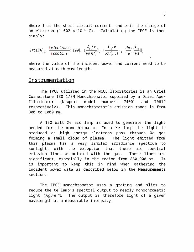
Figure 1. Simplified schematic diagram of the IPCE layout.
Operation of the Monochromator
There are two independent power switches that must be turned on to operate the IPCE shown in Figure 2. Turn on the xenon lamp by pressing the switch on the back of the illuminator (labeled #1 in the diagram) and turn on the monochrometer by flipping the switch on the side of the monochromator (labeled #4 in the diagram). Allow the illuminator lamp to warm up for ~15 minutes before beginning measurements.
The Cornerstone 130 monochromator is controlled by the Newport 74009 Hand Controller seen in Figure 2B. (The instrument can also be connected to a PC (running Windows XP or Newer OS) through a USB cable or through the use of a GPIB interface. For further information see the documentation from Newport.)
A B
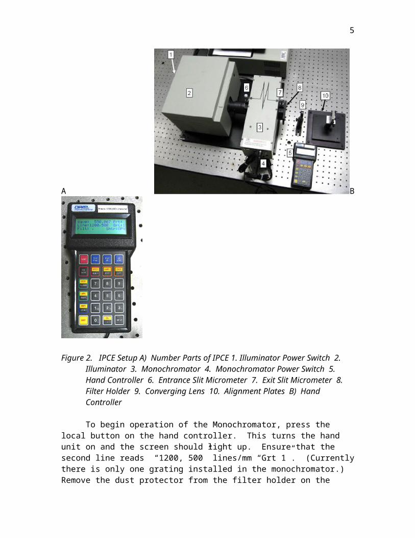
Figure 2. IPCE Setup A) Number Parts of IPCE 1. Illuminator Power Switch 2. Illuminator 3. Monochromator 4. Monochromator Power Switch 5. Hand Controller 6. Entrance Slit Micrometer 7. Exit Slit Micrometer 8. Filter Holder 9. Converging Lens 10. Alignment Plates B) Hand Controller
3
To begin operation of the Monochromator, press the local button on the hand controller. This turns the hand unit on and the screen should light up. Ensure that the second line reads “1200, 500” lines/mm “Grt 1”. (Currently there is only one grating installed in the monochromator.) Remove the dust protector from the filter holder on the front of the instrument. Operation of the monochromator unit using the hand controller is easy and straight forward.
Pressing Go Wave allows you to entering a wavelength between 300 and 1580 nm. After entering a value and pressing the Enter button you should hear the stepper motor advance the grating.
Press the Shutter button to open or close the shutter. Pressing the Step up or Step down button will inc/dec the wavelength by
the smallest possible increments allowed by the stepper motor. Holding the button will scan the wavelength.
Pressing Abort will allow you to cancel a command.
A note about longer wavelengths: When operating the monochromator at wavelengths around ~700 nm and above a significant contribution from the second harmonic can be present and for this reason a long pass filter should be used to eliminate the ½-wavelength component. Failure to do this can give rise to artificial IPCE performance at longer wavelengths. It is suggested that you used the LP665 filter to measure at wavelengths 700 and above. (Most light below 350 nm is absorbed by glass substrates.)
When you have finished using the instrument close the shutter and replace the dust cover and the protective cover over the lens. Turn off both the monochromator and the illuminator.
Measurements
In order to make an IPCE measurement two pieces of information are needed, the number of photons striking the cell and the number of electrons coming out of the cell. To get this data two separate measurements need to be made at each wavelength:
1. The incident power of the light that will hit the active area of the solar cell needs to be accurately measured in order to determine the number of incident photons.
2. The short circuit current of the cell under illumination needs to be recorded in order to calculate the number of generated electrons.
Measurement 1- Incident Power (Number of Photons). When measuring the incident light intensity precise alignment is essential. It is very important that the measurement of the power be made only of photons that will hit the active area of the cell. (If the power meter measures light incident over an area larger than the active area of the cell, then the IPCE value will be underestimated. Similarly, if the power meter measures too small of an area the IPCE will be overestimated.)
4
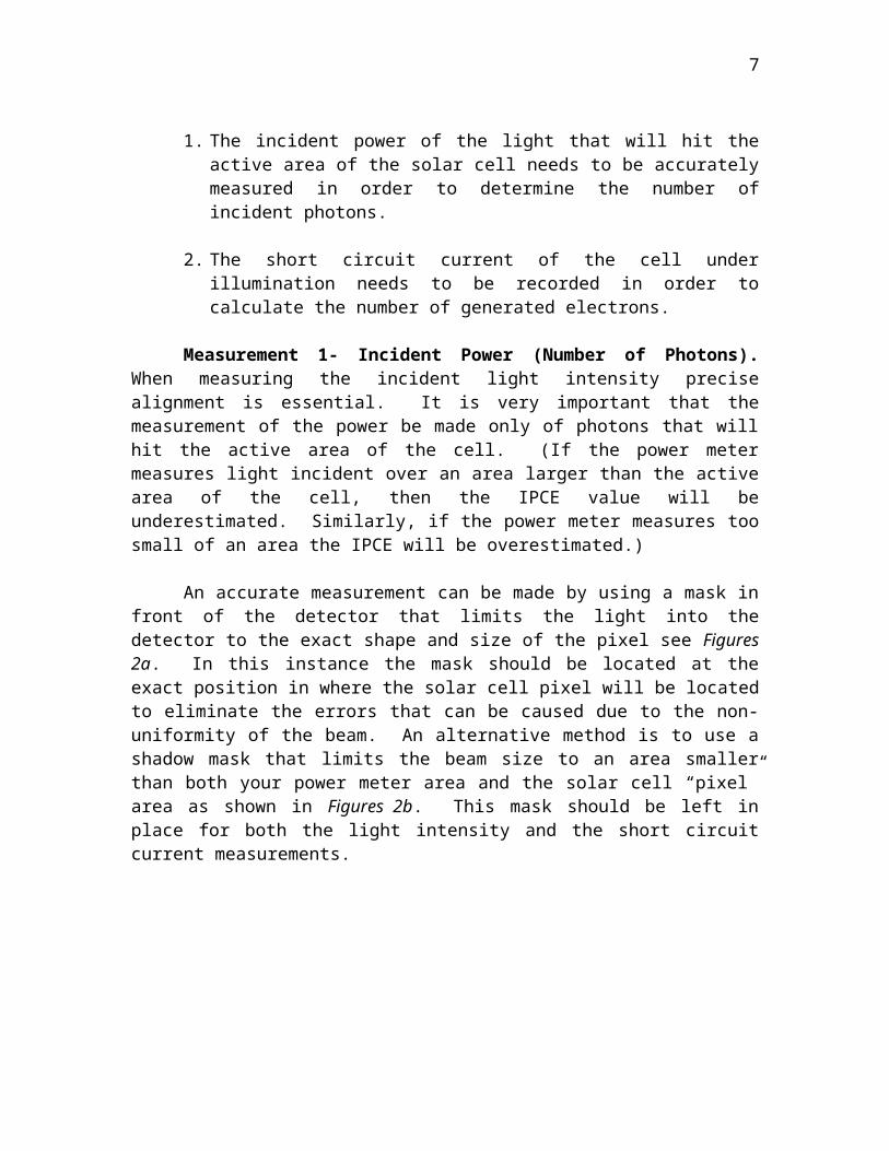
An accurate measurement can be made by using a mask in front of the detector that limits the light into the detector to the exact shape and size of the pixel see Figures 2a. In this instance the mask should be located at the exact position in where the solar cell pixel will be located to eliminate the errors that can be caused due to the non-uniformity of the beam. An alternative method is to use a shadow mask that limits the beam size to an area smaller than both your power meter area and the solar cell “pixel” area as shown in Figures 2b. This mask should be left in place for both the light intensity and the short circuit current measurements.
A
B
Figure 3. Accurate measurement of the incident light intensity should be done by utilizing a shadow mask in such a way that the number of photons incident on the active area of the solar cell are equal to the number incident on the power meter. A) Using a shadow mask that is the exact shape as the solar cell pixel (active area) and placed in the same position means is one method of doing this. B) Use of a shadow mask that limits the size of the beam and is kept in place for both the incident power and the generated current measurements is another valid method.
After the illuminator is properly warmed up and insuring that the beam is properly masked and aligned, the incident power spectrum should be recorded in either 10 or 20 nm increments over the measurement range using the calibrated photodiode power meter. (Ensure to use the proper calibration setting on the power meter.) Due to the spectral lines of the xenon lamp, the incident power spectrum will have several peaks as shown in Figure 4.
5
Incident Spectral Power Distribuition
0
50
100
150
200
250
300 400 500 600 700 800 900 1000
Wavelength(nm)
Pow
er(u
W)
Taken with NO Filter Installed
Taken with LP665 Filter Installed
Figure 4. Incident power spectral distribution of the monochromator with entrance slit set at 300 um, and the exit slit set at 65 um. (Smaller slit widths will make the light more monochromatic but decrease the power- the power distribution will remain the same, but peaks will sharpen and the total power will be lessened.
Measurement 2- Short Circuit Current (Number of Electrons). As with the measurement of the incident power spectrum, proper alignment is very important when measuring the generated current. After insuring the alignment is correct, the measurement process of the current is easy.
Use a sourcemeter such as a Keithley 2400 to maintain a zero bias voltage from the Cathode to Anode of the cell and simultaneously record the short circuit current at each wavelength that you have recorded the incident power intensity at as seen in Figure 5. This data can then be used in the equations given in the above section to calculate the percentage of photons that have been converted to electrons. As an example, Figure 6 contains IPCE data collected from a P3HT:PCBM solar cell.
Figure 5. Incident photon conversion efficiency data taken for a P3HT:PCBM solar cell under ambient conditions at room temperature.
6
Incident Photon Conversion Efficiency
0
10
20
30
40
50
60
70
80
90
100
300 400 500 600 700 800
Wavelength(nm)
Con
vers
ion
Effic
ienc
y(%
)
Figure 6. Incident photon conversion efficiency data taken for a P3HT:PCBM solar cell under ambient conditions at room temperature.
Checking for Consistency between AM1.5 and IPCE data
It is a good idea to compare the results of the incident photon conversion efficiency measurements with the AM1.5 short circuit current measurements. An IPCE measurement is a measurement of short circuit current as a function of wavelength. These values can be used to estimate the total short circuit current that would be generated under AM1.5 illumination conditions.
If a number of incident photons of a particular wavelength is known, the IPCE value (at that wavelength) for the solar cell can be used to determine the number of electrons that will be generated. This number can be very easily converted into a current by multiplying by the charge of an electron (1.602 x 10⁻¹⁹C). To find the IPCE estimated AM1.5 short circuit current one simply needs to perform a weighted sum of these values, based on the AM1.5 photon flux distribution. (The AM1.5 energy flux (units of Wm-2nm-
1s-1) can be downloaded from here: http://rredc.nrel.gov/solar/spectra/am1.5/ and converted into photon flux by multiplying by wavelength and dividing by Planks constant and the speed of light.)
The IPCE estimated AM1.5 short circuit current can be calculated from IPCE measurements by summing [Number of Photons x Fraction Converted to Electrons x Charge of e-)]. This can be written as:
I scIPCE= ∫
Wavelengths( np )λ(
IPCE100
)λ⋅e⋅dλ,
7
where np is the number of photons occurring in the wavelength interval dλ. I have written a simple Excel template that computes this sum and estimates your short circuit current based on your IPCE values. You can download it from the link below.
Templates:
For your reference and use I have posted several Excel templates to our MCCL website and they are available at the following URL’s:
Blank Template: http://www.mccl.chem.ufl.edu/Secure/IPCE-Template-10nm_Steps.xlsWith P3HT DATA: http://www.mccl.chem.ufl.edu/Secure/IPCE-Template_w_Data.xlsXe Spectral PowerDistribution: http://www.mccl.chem.ufl.edu/Secure/Spectral_Distribution.xlsIPCE Short Circuit Current Estimate: http://www.mccl.chem.ufl.edu/Secure/IPCE-Template-Estimating_AM1.5_SC_current.xls
8


![Generation of hydrogen from the Solar Photolysis of Water ... · Potential [mV] I sc = 17.73 mA/cm 2 V oc = 846 mV FF = 0.745 Efficiency = 11.18 80 60 40 20 0 IPCE (%) 400 500 600](https://img.pdfslide.us/doc/110x75/5f9987c736d7854d5e474c66/generation-of-hydrogen-from-the-solar-photolysis-of-water-potential-mv-i-sc.jpg)