Embed Size (px)
Citation preview
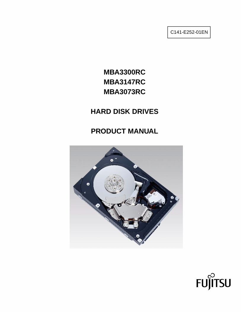
C141-E252-01EN
MBA3300RC MBA3147RC MBA3073RC
HARD DISK DRIVES
PRODUCT MANUAL
C141-E252
FOR SAFE OPERATION
Handling of This Manual
This manual contains important information for using this product. Read thoroughly before using the product. Use this product only after thoroughly reading and understanding especially the section "Important Alert Items" in this manual. Keep this manual handy, and keep it carefully.
FUJITSU makes every effort to prevent users and bystanders from being injured or from suffering damage to their property. Use the product according to this manual.
IMPORTANT NOTE TO USERS
READ THE ENTIRE MANUAL CAREFULLY BEFORE USING THIS PRODUCT. INCORRECT USE OF THE PRODUCT MAY RESULT IN INJURY OR DAMAGE TO USERS, BYSTANDERS OR PROPERTY.
While FUJITSU has sought to ensure the accuracy of all information in this manual, FUJITSU assumes no liability to any party for any damage caused by any error or omission contained in this manual, its updates or supplements, whether such errors or omissions result from negligence, accident, or any other cause. In addition, FUJITSU assumes no liability with respect to the application or use of any product or system in accordance with the descriptions or instructions contained herein; including any liability for incidental or consequential damages arising therefrom. FUJITSU DISCLAIMS ALL WARRANTIES REGARDING THE INFORMATION CONTAINED HEREIN, WHETHER EXPRESSED, IMPLIED, OR STATUTORY.
FUJITSU reserves the right to make changes to any products described herein without further notice and without obligation.
This product is designed and manufactured for use in standard applications such as office work, personal devices and household appliances. This product is not intended for special uses (atomic controls, aeronautic or space systems, mass transport vehicle operating controls, medical devices for life support, or weapons firing controls) where particularly high reliability requirements exist, where the pertinent levels of safety are not guaranteed, or where a failure or operational error could threaten a life or cause a physical injury (hereafter referred to as "mission-critical" use). Customers considering the use of these products for mission-critical applications must have safety-assurance measures in place beforehand. Moreover, they are requested to consult our sales representative before embarking on such specialized use.
The contents of this manual may be revised without prior notice.
The contents of this manual shall not be disclosed in any way or reproduced in any media without the express written permission of Fujitsu Limited.
All Rights Reserved, Copyright FUJITSU LIMITED 2007
C141-E252
REVISION RECORD
Edition Date published Revised contents
01 June, 2007
Specification No.: C141-E252-**EN
C141-E252
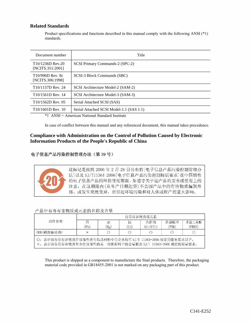
Related Standards
Product specifications and functions described in this manual comply with the following ANSI (*1) standards.
Document number Title
T10/1236D Rev.20 [NCITS.351:2001]
SCSI Primary Commands-2 (SPC-2)
T10/996D Rev. 8c [NCITS.306:1998]
SCSI-3 Block Commands (SBC)
T10/1157D Rev. 24 SCSI Architecture Model-2 (SAM-2)
T10/1561D Rev. 14 SCSI Architecture Model-3 (SAM-3)
T10/1562D Rev. 05 Serial Attached SCSI (SAS)
T10/1601D Rev. 10 Serial Attached SCSI Model-1.1 (SAS 1.1)
*1 ANSI = American National Standard Institute
In case of conflict between this manual and any referenced document, this manual takes precedence.
Compliance with Administration on the Control of Pollution Caused by Electronic Information Products of the People's Republic of China
This product is shipped as a component to manufacture the final products. Therefore, the packaging material code provided in GB18455-2001 is not marked on any packaging part of this product.
C141-E252 1
Preface
This manual describes MBA3300RC, MBA3147RC, and MBA3073RC 3.5 - inch hard disk drives with an embedded Serial Attached SCSI (SAS).
This manual details the specifications and functions of the above disk drive, and gives the requirements and procedures for installing it into a host computer system.
This manual is written for users who have a basic understanding of hard disk drives and their use in computer systems. The MANUAL ORGANIZATION section describes organization and scope of this manual. The need arises, use the other manuals.
The organization of this manual, related reference manual and conventions for alert messages follow.
Overview of Manual
This manual consists of the following seven chapters:
Chapter 1 General Description
This chapter introduces the disk drives standard features, hardware, and system configuration.
Chapter 2 Specifications
This chapter gives detailed specifications of the disk drives and their installation environment.
Chapter 3 Data Format
This chapter describes the data structure, the addressing method, and the defect management.
Chapter 4 Installation Requirements
This chapter describes the basic physical and electrical requirements for installing the disk drives.
Chapter 5 Installation
This chapter explains how to install the disk drives. It includes the notice and procedures for setting device number and operation modes, mounting the disk drive, and confirming drive operation.
Chapter 6 Diagnostics and Maintenance
This chapter describes the automatic diagnosis, and maintenance of the disk drive. This chapter also describes diagnostic methods for operation check and the basics of troubleshooting the disk drives.
Chapter 7 Error Analysis
This chapter describes in details how collect the information for error analysis and how analyze collected error information.
Preface
2 C141-E252
CONVENTIONS USED IN THIS MANUAL
MBA3300RC, MBA3147RC, and MBA3073RC are described as "HDD" in this manual.
Decimal number is represented normally.
Hexadecimal number is represented as X'17B9', 17B9h or 17B9H.
Binary number is represented as "010".
Conventions for Alert Messages
This manual uses the following conventions to show the alert messages. An alert message consists of an alert signal and alert statements. The alert signal consists of an alert symbol and a signal word or just a signal word.
The following are the alert signals and their meanings:
This indicates a hazardous situation could result in minor or moderate personal injury if the user does not perform the procedure correctly. This alert signal also indicates that damages to the product or other property, may occur if the user does not perform the product correctly.
This indicates information that could help the user use the product more efficiently.
In the text, the alert signal is centered, followed below by the indented message. A wider line space precedes and follows the alert message to show where the alert message begins and ends. The following is an example:
(Example)
Damage Never remove any labels from the HDD or deface them in any way.
The main alert messages in the text are also listed in the "Important Alert Items."
Attention
Please forward any comments you may have regarding this manual.
To make this manual easier for users to understand, opinions from readers are needed. Please write your opinions or requests on the Comment at the back of this manual and forward it to the address described in the sheet.
C141-E252 3
Important Alert Items
Important Alert Messages
The important alert messages in this manual are as follows:
A hazardous situation could result in minor or moderate personal injury if the user does not perform the procedure correctly. Also, damage to the product or other property, may occur if the user does not perform the procedure correctly.
Task Alert message Page
Installation Damage
Never remove any labels from the HDD or deface them in any way.
44
High temperature
To prevent injury, never touch the HDD while it is hot. The DE and LSI become hot during operation and remain hot immediately after turning off the power.
55, 64
Damage
1. When dismounting the HDD which is mounted on the system while power is supplied to it.
1) Stop the spindle motor by a START/STOP UNIT command. It takes about 30 seconds for the spindle motor to stop completely.
2) Then, dismount the HDD using the drive mounting/dismounting mechanism, etc. of the system. When removing the HDD, avoid exposing it to shock or vibration. Just in case, stop dismounting once when SAS connector breaks off contact and wait until the spindle motor stops (about 30 seconds.).
64
2. When dismounting the HDD which is mounted on the system while power is not supplied to it.
• Dismount the HDD using the HDD mounting/dismounting mechanism, etc. of the system. When removing the HDD, avoid exposing it to shock or vibration.
3. When storing or transporting the HDD, put it in the antistatic case (Fcell) (refer to Section 5.1 and 6.5).
Important Alert Items
4 C141-E252
Task Alert message Page
Diagnostics and Maintenance
Data loss
Save data stored on the HDD to other media before requesting repair. Fujitsu does not assume responsibility if data is corrupted during servicing or repair.
69
High temperature
To prevent injury, never touch the HDD while it is hot. The DE and LSI become hot during operation and remain hot immediately after turning off the power.
69
Electrical shock
Never touch the HDDs while power-feeding.
69
Damage
• Always ground yourself with a wrist strap connected to ground before handling. ESD (Electrostatics Discharge) may cause the damage to the device.
• Never use a conductive cleaner to clean the HDDs.
• Never remove any labels from the HDD or deface them in any way.
• Never remove the PCBA.
• Never open the HDD for any reason.
69
Damage
• Never remove any labels from the HDD or deface them in any way.
• Never open the HDD for any reason. Doing so will void any warranties.
76
C141-E252 5
MANUAL ORGANIZATION
PRODUCT MANUAL
(This manual)
1. General Description 2. Specifications 3. Data Format 4. Installation Requirements 5. Installation 6. Diagnostics and Maintenance 7. Error Analysis
SAS INTERFACE MANUAL
1. SAS Interface 2. Command Processing 3. Data Buffer Management 4. Command Specifications 5. Parameter Data Format 6. Sense Data and Error Recovery Methods 7. Disk Media Management

This page is intentionally left blank.
C141-E252 7
CONTENTS
Preface ....................................................................................................................1
Important Alert Items .............................................................................................3
MANUAL ORGANIZATION.....................................................................................5
CHAPTER 1 General Description....................................................................13
1.1 Standard Features......................................................................................13
1.2 Hardware Structure ...................................................................................17
1.3 System Configuration ...............................................................................18
CHAPTER 2 Specifications .............................................................................19
2.1 Hardware Specifications ...........................................................................19 2.1.1 Model name and order number .................................................................19 2.1.2 Function specifications .............................................................................20 2.1.3 Environmental specifications....................................................................23 2.1.4 Error rate ...................................................................................................24 2.1.5 Reliability..................................................................................................24
CHAPTER 3 Data Format.................................................................................27
3.1 Data Space ................................................................................................27 3.1.1 Cylinder configuration..............................................................................27 3.1.2 Alternate spare area ..................................................................................30 3.1.3 Track format..............................................................................................31 3.1.4 Sector format.............................................................................................32 3.1.5 Format capacity.........................................................................................34
3.2 Logical Data Block Addressing................................................................34
Contents
8 C141-E252
3.3 Defect Management ................................................................................. 36 3.3.1 Defect list ................................................................................................. 36 3.3.2 Alternate block allocation ........................................................................ 36
CHAPTER 4 Installation Requirements.......................................................... 41
4.1 Mounting Requirements........................................................................... 41 4.1.1 Dimensions............................................................................................... 41 4.1.2 Mounting orientations .............................................................................. 43 4.1.3 Notes on mounting ................................................................................... 44
4.2 Power Supply Requirements .................................................................... 48
4.3 Connection Requirements ........................................................................ 50 4.3.1 Connector location ................................................................................... 50 4.3.2 Interface connector................................................................................... 51 4.3.3 Ready LED output signal ......................................................................... 53 4.3.4 Connector requirements ........................................................................... 53
CHAPTER 5 Installation .................................................................................. 55
5.1 Notes on Handling HDDs ........................................................................ 55
5.2 Setting ...................................................................................................... 57 5.2.1 Port Address ............................................................................................. 57
5.3 Mounting HDDs....................................................................................... 57 5.3.1 Mounting procedures ............................................................................... 57
5.4 Checking Operation after Installation and Preparing the HDDs for Use...................................................................................................... 58
5.4.1 Checking initial operation........................................................................ 58 5.4.2 Formatting ................................................................................................ 59 5.4.3 Setting parameters.................................................................................... 61
5.5 Dismounting HDDs.................................................................................. 64
Contents
C141-E252 9
CHAPTER 6 Diagnostics and Maintenance ...................................................65
6.1 Diagnostics................................................................................................65 6.1.1 Self-diagnostics.........................................................................................65 6.1.2 Test programs............................................................................................68
6.2 Maintenance..............................................................................................69 6.2.1 Precautions................................................................................................69 6.2.2 Maintenance requirements........................................................................70 6.2.3 Maintenance levels ...................................................................................71 6.2.4 Tools and test equipment ..........................................................................71 6.2.5 Tests ..........................................................................................................72
6.3 Operation Check .......................................................................................73 6.3.1 Initial seek operation check ......................................................................73 6.3.2 Operation test ............................................................................................73 6.3.3 Diagnostic test...........................................................................................73
6.4 Troubleshooting ........................................................................................74 6.4.1 Outline of troubleshooting procedures .....................................................74 6.4.2 Troubleshooting with HDD replacement in the field ...............................74 6.4.3 Troubleshooting at the repair site .............................................................76 6.4.4 Troubleshooting with parts replacement in the factory ............................77 6.4.5 Finding possibly faulty parts.....................................................................77
6.5 Packaging..................................................................................................77 6.5.1 Unitary packaging.....................................................................................77 6.5.2 Multi box packaging .................................................................................78
CHAPTER 7 Error Analysis .............................................................................81
7.1 Sense Data Collection...............................................................................81 7.1.1 Sense data..................................................................................................81 7.1.2 Sense data format......................................................................................81
7.2 Sense Data Analysis..................................................................................83 7.2.1 Error information indicated with sense data.............................................83 7.2.2 Sense data (3-0C-03), (4-32-01), (4-40-xx), (4-C4-xx),
and (4-44-xx) ............................................................................................84 7.2.3 Sense data (1-1x-xx), (3-1x-xx) and (E-1D-00): Disk read error............84
Contents
10 C141-E252
7.2.4 Sense data (5-2x-xx), (B-47-xx), (B-4B-xx) and (B-4E-00): interface error........................................................................................... 84
Glossary ..................................................................................................... 85
Abbreviation ..................................................................................................... 87
Index ..................................................................................................... 89
Contents
C141-E252 11
Illustrations
Figures
Figure 1.1 Example of SAS system configuration (Dual port internal cabled environment) ...................................................................... 18
Figure 1.2 Example of SAS system configuration (Dual port internal backplane environment) ................................................................ 18
Figure 3.1 Cylinder configuration................................................................... 28 Figure 3.2 Spare area in cell ........................................................................... 30 Figure 3.3 Alternate cylinder .......................................................................... 30 Figure 3.4 Track format .................................................................................. 31 Figure 3.5 Track skew/head skew................................................................... 32 Figure 3.6 Sector format ................................................................................. 32 Figure 3.7 Alternate block allocation by FORMAT UNIT command............ 37 Figure 3.8 Alternate block allocation by REASSIGN BLOCKS
command ....................................................................................... 38 Figure 4.1 Dimensions .................................................................................... 42 Figure 4.2 HDD orientations........................................................................... 43 Figure 4.3 Mounting frame structure example ............................................... 44 Figure 4.4 Limitation of side-mounting.......................................................... 45 Figure 4.5 Surface temperature measurement points ..................................... 46 Figure 4.6 Current waveform (Spin-up) ........................................................ 48 Figure 4.7 Current waveform (Max seek)...................................................... 49 Figure 4.8 AC noise filter ............................................................................... 50 Figure 4.9 Connector location......................................................................... 50 Figure 4.10 SAS plug connector overview ....................................................... 51 Figure 4.11 Recommended external circuit for Ready LED output ................. 53 Figure 6.1 Test flowchart ................................................................................ 72 Figure 6.2 Unitary packaging ......................................................................... 77 Figure 6.3 Multi box packaging...................................................................... 78 Figure 6.4 Fraction packaging ........................................................................ 79 Figure 7.1 Sense data format .......................................................................... 82
Contents
12 C141-E252
Tables
Table 2.1 Model names and order numbers................................................... 19 Table 2.2 Function specifications .................................................................. 20 Table 2.3 Environmental/Power requirements .............................................. 23 Table 3.1 Format capacity ............................................................................. 34 Table 4.1 Surface temperature check point and maximum temperature ....... 46 Table 4.2 Interface connector (SAS plug) signal allocation:CN1 ................. 52 Table 4.3 Recommended connectors ............................................................. 53 Table 6.1 Self-diagnostic functions ............................................................... 65 Table 6.2 System-level field troubleshooting................................................ 75 Table 6.3 HDD troubleshooting..................................................................... 76 Table 7.1 Definition of sense data ................................................................. 83
C141-E252 13
CHAPTER 1 General Description
1.1 Standard Features
1.2 Hardware Structure
1.3 System Configuration
This chapter describes the feature and configuration of the MBA3xxxRC. The HDDs are high performance large capacity 3.5-inch hard disk drives with an embedded Serial Attached SCSI (SAS) controller. The interface used to connect the HDDs to the host system complies with ANSI T10/1601-D Serial Attached SCSI-1.1 (SAS-1.1), which covers items ranging from SAS physical layers to SCSI command protocols. The high-speed data transfer and long-distance transmission capabilities of SAS technology and the powerful command set the HDD facilitate creation of high-performance and highly reliable disk subsystems with large storage capacities. 1.1 Standard Features
(1) Compactness
The HDDs are a compact enclosure which complies with the 3.5-inch hard disk drive form factor. (2) Environmental Protection
The HDDs comply with the Restriction of the use of certain Hazardous Substances in electrical and electronic equipment (RoHS) directive issued by European Union (EU).
(3) SAS Standard
The HDDs are equipped with a serial attached SCSI (SAS) as a host interface.
• Transfer rate: 1.5Gbps, 3.0Gbps • Number of SAS ports: Two • Full-duplex (simultaneous bidirectional data transfer) is supported.
General Description
14 C141-E252
(4) Dual SAS port support
The HDDs have two pairs of driver and receiver set (PHY) for the SAS to support dual SAS port connection.
On the HDDs, Primary and Secondary Ports on SAS plug connector (2 physical links plus power
connections) are used for SAS port connection. (5) High-speed data transfer
The maximum data-transfer speed on the SAS is 300.0 MB/s. The large-capacity data buffer of the HDDs enable the effective use of such high-speed data transfers available on the SAS connection.
(6) Continuous block processing
The addressing method of data blocks is logical block address. The initiator can access data by specifying block number in a logically continuous data space without concerning the physical structure of the track or cylinder boundaries.
The continuous processing up to [64K-1] blocks in a command can be achieved, and the HDDs can
perform continuous read/write operation when processing data blocks on several tracks or cylinder. (7) Multi-segment data buffer
The data buffer is 16M bytes. Data are transferred between SAS port and disk media through this data buffer. This feature provides the suitable usage environment for users.
(8) Cache feature
After executing the READ command, the HDDs read automatically and store (prefetches) the subsequent data blocks into the data buffer (Read-ahead caching).
The high speed sequential data access can be achieved by transferring the data from the data buffer without
reaccessing the disk in case the subsequent command requests the prefetched data blocks. The Write Cache feature is supported. When this feature is enabled, the status report is issued
without waiting for completion of write processing to disk media, thereby enabling high speed write processing.
When Write Cache is enabled, you should ensure that the cached data is surely flushed to the disk media before you turn off the HDDs power.
To ensure it, you should issue either the SYNCHRONIZE CACHE command or the STOP UNIT command with specifying "0" to the Immediate bit, and then confirm that the command is surely terminated with the GOOD STATUS.
1.1 Standard Features
C141-E252 15
(9) Command queuing feature
The HDDs can queue maximum 128 commands, and optimizes the issuing order of queued commands by the reordering function. This feature realizes the high speed processing.
(10) Reserve and release functions The HDDs can be accessed exclusively in the multi-host or multi-initiator environment by using the
reserve and release functions. (11) Error recovery The HDDs can try to recover from errors in the HDD using its powerful retry processing. If a
recoverable data check occurs, error-free data can be transferred to the initiator after being corrected in the data buffer. The initiator software is released from the complicated error recover processing by these error recovery functions of the HDDs.
(12) Automatic alternate block reassignment If a defective data block is detected during read or write the HDDs can automatically reassign their
alternate data block. (13) Programmable data block length
Data can be accessed in fixed-block length units. The data block length is programmable, and can be specified at initializing with a multiple of four within the range of 512 to 528 bytes.
Error rate increase
1. The drive format at factory shipment is generally 512 bytes.
2. The recoverable Error might increase when the format would be modified from 512 bytes to the following values:
516 bytes, 520 bytes, 524 bytes, 528 bytes.
3. The recoverable Error referred here is sense data (1-13-xx). (14) Defective block slipping
A logical data block can be reallocated in a physical sequence by slipping the defective data block at formatting. This results in high speed contiguous data block processing without a revolution delay due to defective data block.
(15) High speed positioning
A rotary voice coil motor achieves fast positioning with high performance access control.
General Description
16 C141-E252
(16) Large capacity
A large capacity can be obtained from the HDDs by dividing all cylinders into several partitions and changing the recording density on each partition (constant density recording). The disk subsystem with large capacity can be constructed in the good space efficiency.
(17) Start/Stop of spindle motor
Using the SAS primitive or the SCSI command, the host system can start and stop the spindle motor. (18) Diagnosis
The HDDs have a diagnostic capability which checks internal controller functions and HDD operations. Also, for early detection of and recovery from the errors on the disk, the HDD has a function for periodically implementing a full scan of the disk.
(19) Low power consumption
By using highly integrated LSI components, the power consumption of the HDDs is very low, and this enables the units to be used in wide range of environmental conditions.
(20) Low acoustic noise
The acoustic noise level is low; approx. 3.6 Bels at Idle. This makes it ideal for office use. (21) Microcode downloading
The HDDs implement the microcode download feature. This feature easily achieves maintenance and function enhancement of the HDDs.
1.2 Hardware Structure
C141-E252 17
1.2 Hardware Structure
The HDDs have a disk enclosure (DE) and a printed circuit board assembly (PCBA). The DE includes heads on an actuator and disks on a spindle motor mounted on the DE. The PCBA includes a read/write circuit and a controller circuit.
(1) Disks
The disks have an outer diameter of 70 mm (2.8 inch). (2) Heads
The heads have MR (Magnet – Resistive) read element Ramp Load type slider. (3) Spindle motor
The disks are rotated by a direct-drive hall-less DC motor. The motor speed is controlled by a feedback circuit using the counter electromotive current to precisely maintain the specified speed.
(4) Actuator
The actuator, which uses a rotary voice coil motor (VCM), consumes little power and generates little heat. The heads at the end of the actuator arm are controlled and positioned via feedback servo loop.
The heads are positioned on the ramp when the power is off or the spindle motor is stopped. (5) Read/write circuit
The read/write circuit utilizes a read channel mounted with a head IC that supports high-speed transmission and an MEEPRML (Modified Enhanced Extended Partial Response Maximum Likelihood) modulation/demodulation circuit in order to prevent errors being triggered by external noise and to improve data reliability.
(6) Controller circuit
The controller circuit uses LSIs to increase the reliability and uses a high speed microprocessing unit (MPU) to increase the performance of the SAS controller.
General Description
18 C141-E252
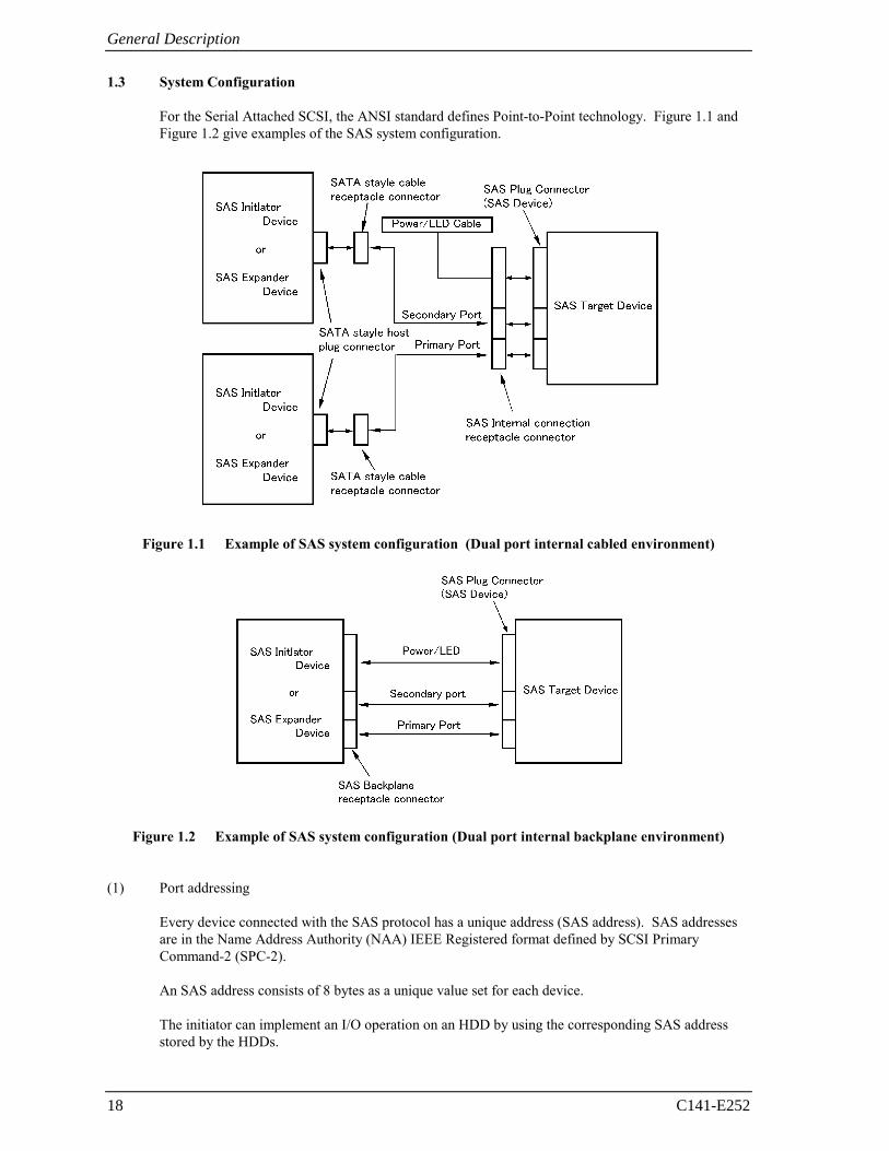
1.3 System Configuration
For the Serial Attached SCSI, the ANSI standard defines Point-to-Point technology. Figure 1.1 and Figure 1.2 give examples of the SAS system configuration.
Figure 1.1 Example of SAS system configuration (Dual port internal cabled environment)
Figure 1.2 Example of SAS system configuration (Dual port internal backplane environment)
(1) Port addressing Every device connected with the SAS protocol has a unique address (SAS address). SAS addresses
are in the Name Address Authority (NAA) IEEE Registered format defined by SCSI Primary Command-2 (SPC-2).
An SAS address consists of 8 bytes as a unique value set for each device. The initiator can implement an I/O operation on an HDD by using the corresponding SAS address
stored by the HDDs.
C141-E252 19
CHAPTER 2 Specifications
2.1 Hardware Specifications
This chapter describes specifications of the HDDs. 2.1 Hardware Specifications
2.1.1 Model name and order number
Each model has different recording capacities.
Table 2.1 lists the model name and order number.
The data format can be changed by reinitializing with the user's system.
Table 2.1 Model names and order numbers
Model name Order number Interface type Capacity (user area)
MBA3300RC CA06778-B400 SAS 300 GB (*)
MBA3147RC CA06778-B200 SAS 147 GB (*)
MBA3073RC CA06778-B100 SAS 73.5 GB (*)
(*) One gigabyte (GB) = one billion bytes; accessible capacity will be less and actual capacity depends on the operating environment and formatting.
Specifications
2.1.2 Function specifications
Table 2.2 shows the function specifications of the HDDs.
Table 2.2 Function specifications
Specification Item
MBA3300RC MBA3147RC MBA3073RC
Formatted capacity (*1) 300 GB (*2) 147 GB (*2) 73.5 GB (*2)
Number of disks 4 2 1
Number of heads 8 4 2
Tracks per Surface 82604 cyl typ. (standard format including the alternate cylinder)
Recording mode 60/62 MEEPRML
Areal density 124.7 Gbit/inch2
Max Recording Density 860 kBPI
Track Density 145 kTPI typ.
Track to Track 0.2 ms / 0.4 ms
Average 3.4 ms / 3.9 ms Seek time (*3) (Read/Write)
Full stroke 8.0 ms / 9.0 ms
Number of rotations 15,000 ± 0.2 % min-1 (rpm)
Average latency time 2.0 ms
Start/stop time (*4)
Ready up time
Stop time
30 s typ. (60 s max.)
30 s typ.
External dimensions
Height
Width
Length
26.1 mm max.
101.6 mm ± 0.25mm
147.0 mm max.
Weight 0.8 kg max.
Power consumption (*5) 12.36 W typ.
Internal 188 MB/s (standard format, most outer) Data transfer rate (*6) External 1.5 Gbps, 3 Gbps
Logical data block length 512 to 528 byte (fixed length) (*7)
Related standards
SAS (T10/1562D Rev. 05), SAS1.1 (T10/1601D Rev. 07), SAM-3 (T10/1561D Rev. 14), SAM-2 (T10/1157D Rev. 24),
SPC-2 (T10/1236D Rev. 20), SBC (T10/996D Rev. 8c), Eye mask (*8)
Data buffer 16 MB FIFO ring buffer (*9)
Acoustic noise (Idle) 3.6 Bels typ.
20 C141-E252
2.1 Hardware Specifications
C141-E252 21
(*1) The formatted capacity can be changed by changing the logical block length and using spare sector space. See Chapter 3 for the further information. The formatted capacity listed in the table is an estimate for 512 bytes per sector.
(*2) One gigabyte (GB) = one billion bytes; accessible capacity will be less and actual capacity depends on the operating environment and formatting.
(*3) The seek time is as follows:
(*4) The start time is the time from power on or start command to when the HDDs are ready, and the stop
time is the time for disks to completely stop from power off or stop command.
(*5) This value indicates in idle mode. Power supply at nominal voltage ±1%. 25°C ambient.
(*6) The maximum data transfer rate may be restricted to the response speed of initiator and by transmission characteristics. 1 MB/s = 1,000,000 bytes/s.
(*7) Refer to 1.1 (13).
Specifications
22 C141-E252
(*8) The eye mask is as follows:
Normalized time [U1]
Parameter Unit 1.5Gbps 3.0Gbps
2xZ2 mVp-p 1,600 1,600
2xZ1 mVp-p 325 275
X1 UI 0.275 0.275
X2 UI 0.5 0.5
(*9) 1 MB = 1,048,576 bytes.
Abs
olut
e am
plitu
de [V
]
2.1 Hardware Specifications
2.1.3 Environmental specifications
Table 2.3 lists environmental and power requirements.
Table 2.3 Environmental/Power requirements (1/2)
Specification Item
MBA3300RC MBA3174RC MBA3073RC
Operating 5 to 55 °C Non-operating –40 to 70 °C Transport –40 to 70 °C DE surface temperature at operating 5 to 60 °C
Temperature (*1)
Gradient 20 °C/h or less Operating 5 to 95 %RH Non operating 5 to 95 %RH Transport 5 to 95 %RH
Relative humidity
Maximum wet bulb temperature 29 °C (no condensation) Operating (*3) 0.6 mm (5 to 20Hz) / 9.8 m/s2 (1G) (20 to 300 Hz) or less Non-operating (*4) 3.1 mm (5 to 20Hz) / 49 m/s2 (5G) (20 to 300Hz) or less Vibration
(*2) Transport (packaged) 3.1 mm (5 to 20Hz) / 49 m/s2 (5G) (20 to 300Hz) or less Operating 637.4 m/s2 (65G) (2ms) Non-operating 2451.7 m/s2 (250G) (2ms) Shock (*2) Transport (packaged) 2451.7 m/s2 (250G) (2ms) Operating –305 to +3,048 m (–1,000 to +10,000 feet)
Altitude Non-operating –305 to +12,192m (–1,000 to +40,000 feet)
Regulation ±5% Ready (average) 0.88A 0.60A 0.45A
Spin up 2.5A (peak) 3.5A (less than 100µs)
Peak operating current Maximum (peak) DC (*6)
2.8A 2.5A 2.3A +12V DC
Peak operating current DC (reference) (*6)
1.15A 0.9A 0.75A
Regulation ±5%
Ready (average) 0.5A
Peak operating current Maximum (peak) DC (*6)
1.5A
Power requirement (*5)
+5V DC
Peak operating current DC (reference) (*6)
0.79A
C141-E252 23
Specifications
24 C141-E252
Table 2.3 Environmental/Power requirements (2/2)
Specification Item
MBA3300RC MBA3174RC MBA3073RC
Power requirement (*5)
Ripple (+5V, +12V) 250mVp-p or less (*7)
(*1) For detail condition, see Section 4.1.
(*2) Vibration applied to the HDD is measured at near the mounting screw hole on the frame as much as possible.
(*3) At random seek write/read and default on retry setting with log sweep vibration.
(*4) At power-off state after installation
(*5) Input voltages are specified at the HDD connector side, during HDD Idle state.
(*6) Operating currents are values under random W/R operation of full partition at about 220 IOPS.
(*7) High frequency noise (over 20MHz) is less than 100 mVp-p.
2.1.4 Error rate
Errors detected during initialization and replaced by alternate block assignments are not included in the error rate. Data blocks to be accessed should be distributed over the disk equally.
(1) Unrecoverable error rate
Errors which cannot be recovered within 63 retries and ECC correction should not exceed 10 per 1016 bits read.
(2) Positioning error rate
Positioning errors which can be recovered by one retry should be 10 or less per 108 seeks.
2.1.5 Reliability
(1) Mean Time Between Failures (MTBF)
MTBF of the HDDs during their life time is 1,400,000 hours (operating: 24 hours/day, 7 days/week average DE surface temperature: 50°C or less). Continual or sustained operation at case DE surface temperature above 50°C may degrade product reliability.
2.1 Hardware Specifications
C141-E252 25
Note:
The MTBF is defined as:
Operating time (hours) at all field sites MTBF =
The number of equipment failures from all field sites Failure of the equipment means failure that requires repair, adjustments, or replacement.
Mishandling by the operator, failures due to bad environmental conditions, power trouble, host system trouble, cable failures, or other failures not caused by the equipment are not considered.
(2) Mean Time To Repair (MTTR)
MTTR is the average time taken by a well-trained service mechanic to diagnose and repair an HDD malfunction. The HDD is designed for a MTTR of 30 minutes or less.
(3) Service life
The service life under suitable conditions and treatment is as follows.
The service life is depending on the environment temperature. Therefore, the user must design the system cabinet so that the average DE surface temperature is as low as possible.
• DE surface temperature: from 5ºC to 40ºC 5 years • DE surface temperature: from 41ºC to 45ºC 4.5 years • DE surface temperature: from 46ºC to 50ºC 4 years • DE surface temperature: from 51ºC to 55ºC 3.5 years • DE surface temperature: from 56ºC to 60ºC 3 years • DE surface temperature: more than 60ºC or less than 5ºC
No guarantee (Keep the DE surface temperature from 5°C to 60°C.)
Even if the HDDs are used intermittently, the longest service life is 5 years.
The maximum storage period without turning the power on is six months.
Note:
The "average DE surface temperature" means the average temperature at the DE surface throughout the year when the HDDs are operating.

Specifications
26 C141-E252
(4) Data security at power failure Integrity of the data on the disk is guaranteed against all forms of DC power failure except on blocks
where a write operation is being performed. The above does not applied to formatting disks or assigning alternate blocks.
C141-E252 27
CHAPTER 3 Data Format
3.1 Data Space
3.2 Logical Data Block Addressing
3.3 Defect Management
This chapter explains data space definition, logical data block addressing, and defect management on the HDDs. 3.1 Data Space
The HDDs manage the entire data storage area divided into the following three data spaces.
• User space: Storage area for user data
• Internal test space: Reserved area for diagnostic purposes
• System space: Area for exclusive use of HDDs themselves
The user space allows a user access by specifying data. These spaces can be accessed with the logical data block addressing method described in Section 3.2. The internal test space is used by Read/write test of self-diagnostics test, but user can't use direct access. The system space is accessed inside the HDDs at power-on or during the execution of a specific command, but the user cannot directly access the system space.
3.1.1 Cylinder configuration
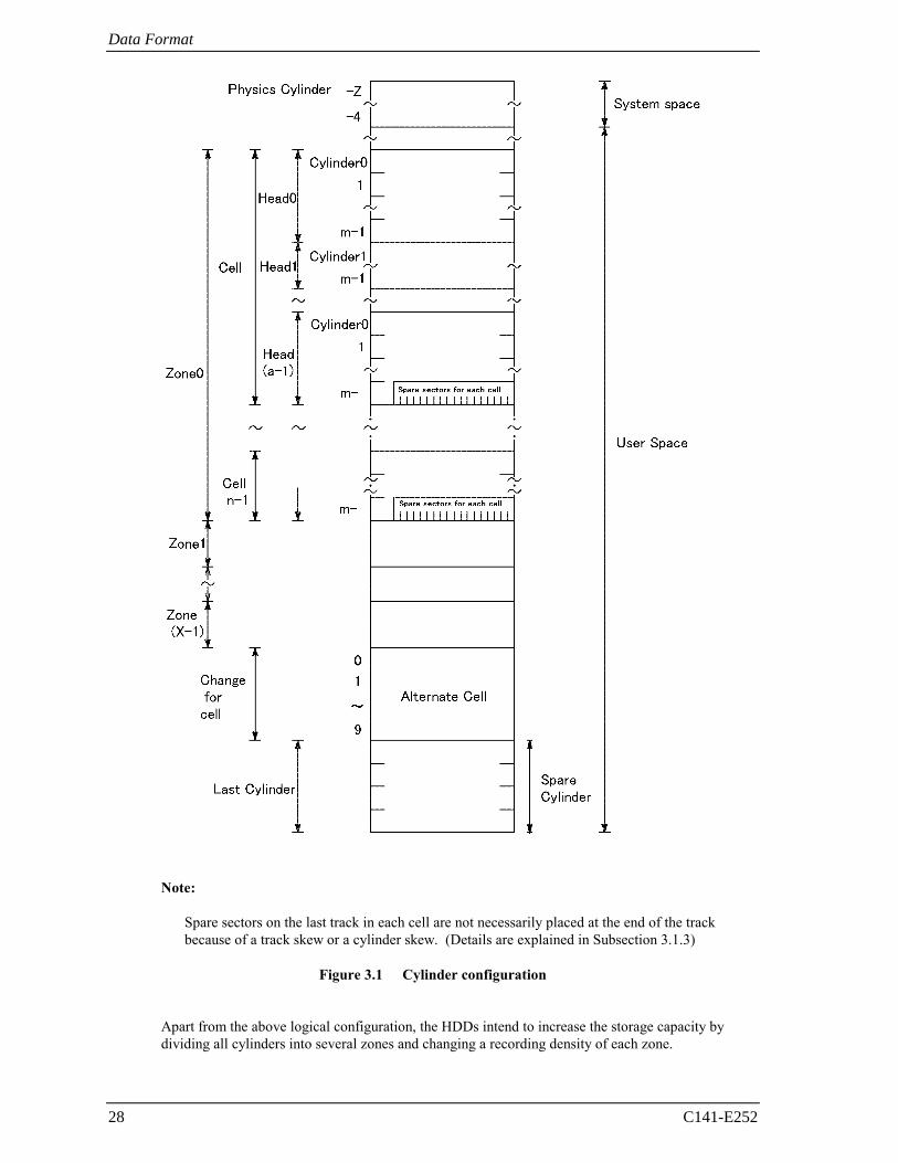
The HDDs allocate cylinders to the user space, internal test space, and system space. Figure 3.1 is the cylinder configuration.
Spare areas (alternate areas) for defective sectors are provided in the user space. Several sectors in the last track of each cell and the last 10 cylinders of the last zone are allocated as alternate areas according to the user's assignment (MODE SELECT command). See Subsection 3.1.2 for details.
Data Format
28 C141-E252
Note:
Spare sectors on the last track in each cell are not necessarily placed at the end of the track because of a track skew or a cylinder skew. (Details are explained in Subsection 3.1.3)
Figure 3.1 Cylinder configuration
Apart from the above logical configuration, the HDDs intend to increase the storage capacity by
dividing all cylinders into several zones and changing a recording density of each zone.
3.1 Data Space
C141-E252 29
(1) User space
The user space is a storage area for user data. The data format on the user space (the length of data block and the number of data blocks) can be specified with the MODE SELECT or MODE SELECT EXTENDED command.
The user can also specify the number of logical data blocks to be placed in the user space with the MODE SELECT or MODE SELECT EXTENDED command. When the number of logical data blocks is specified, as many cylinders as required to place the specified data blocks are allocated in the user space.
A number starting with 0 is assigned to each cylinder required in the user space in ascending order. If the number of cylinders do not reach the maximum, the rest of the cylinders will not be used.
Always 10 cylinders are located at the end of the last zone in the user space as an alternate cylinder. Alternate cylinders will be used for alternate blocks. See Subsections 3.1.2 and 3.3.2 for details.
(2) Internal test space
The internal test space is an area for diagnostic purposes only and its data block length is always 512Byte. The internal test space consists of 8 cylinders and outer-most cylinder is always assigned (cylinder −223 to −230). The user cannot change the number of cylinders in the internal test space or their positions.
(3) System space
The system space is an area for exclusive use of the HDDs themselves and the following information are recorded.
• Defect list (P list and G list) • MODE SELECT parameter (saved value) • Statistical information (log data) • Controller control information
The above information is duplicated in several different locations for safety.
Note:
The system space is also called SA space.
Data Format
30 C141-E252
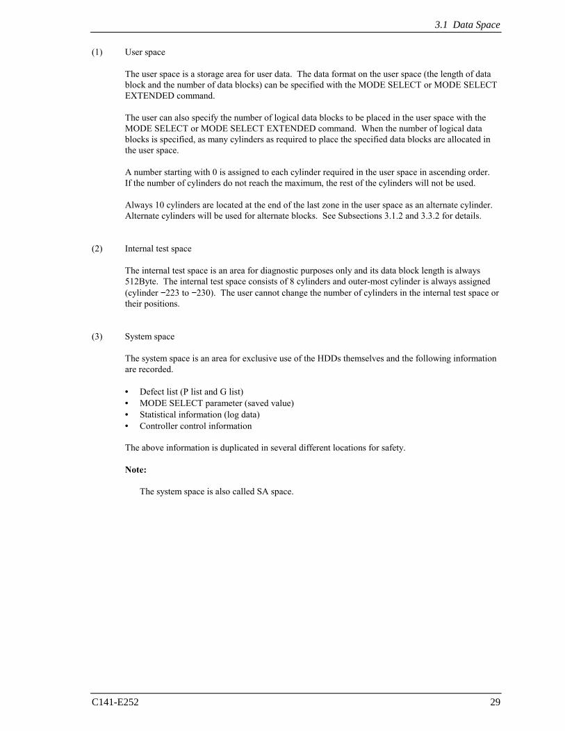
3.1.2 Alternate spare area
The alternate spare area consists of the last track of each cell in the user space and an alternate cylinder allocated to the last 10 cylinders of the last zone in the user space.
The spare area in each cell is placed at the end of the last track as shown in Figure 3.2. These spare sectors are located in the end of the track logically, not necessarily located at the end physically because of track skew or cylinder skew. (Details are explained on Subsection 3.1.3.)
Size can be specified by the MODE SELECT command.
The number of spare sectors per cell is fixed at 300. This number cannot be changed by users.
SPR299 SPR300
300
Note:
This HDD manages alternate spare areas for each cell, which is a set of cylinders. One cell consists of 40 cylinders.
Figure 3.2 Spare area in cell
The alternate cylinder is used for replacement action via the REASSIGN BLOCKS command or
automatic replacement processing. The alternate cylinder is allocated to 10 cylinders at the end of the last zone in the user space.
Note:
The number of alternate cylinders cannot be changed.
Figure 3.3 Alternate cylinder
Cell
3.1 Data Space
C141-E252 31
3.1.3 Track format
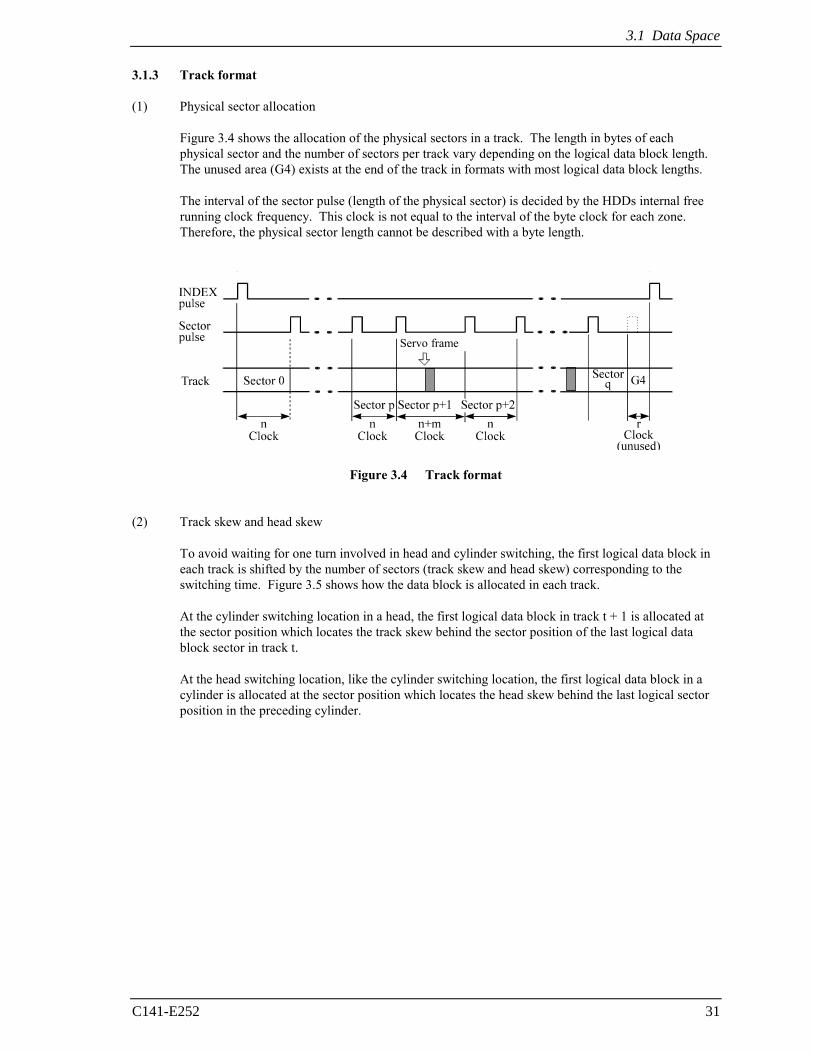
(1) Physical sector allocation
Figure 3.4 shows the allocation of the physical sectors in a track. The length in bytes of each physical sector and the number of sectors per track vary depending on the logical data block length. The unused area (G4) exists at the end of the track in formats with most logical data block lengths.
The interval of the sector pulse (length of the physical sector) is decided by the HDDs internal free running clock frequency. This clock is not equal to the interval of the byte clock for each zone. Therefore, the physical sector length cannot be described with a byte length.
Servo frame
Figure 3.4 Track format
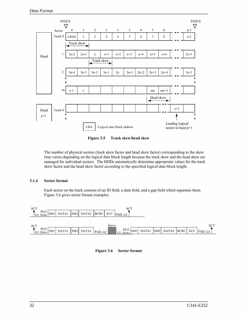
(2) Track skew and head skew
To avoid waiting for one turn involved in head and cylinder switching, the first logical data block in each track is shifted by the number of sectors (track skew and head skew) corresponding to the switching time. Figure 3.5 shows how the data block is allocated in each track.
At the cylinder switching location in a head, the first logical data block in track t + 1 is allocated at the sector position which locates the track skew behind the sector position of the last logical data block sector in track t.
At the head switching location, like the cylinder switching location, the first logical data block in a cylinder is allocated at the sector position which locates the head skew behind the last logical sector position in the preceding cylinder.
Data Format
32 C141-E252
Head
Track skew
Track skew
Head skew
Leading logical sector in head p+1
Head
Figure 3.5 Track skew/head skew
The number of physical sectors (track skew factor and head skew factor) corresponding to the skew
time varies depending on the logical data block length because the track skew and the head skew are managed for individual sectors. The HDDs automatically determine appropriate values for the track skew factor and the head skew factor according to the specified logical data block length.
3.1.4 Sector format
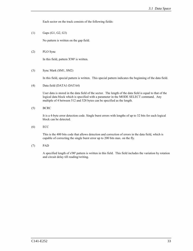
Each sector on the track consists of an ID field, a data field, and a gap field which separates them. Figure 3.6 gives sector format examples.
SCT
PADSM1PLOSyncG1
SCT
G2DATA1 SM2 BCRCDATA2 ECC
SCT
PADSM1PLOSyncG1
SCT
G3DATA1 SM2 DATA3 PAD G2 SM1PLOSyncG1 DATA1 SM2 DATA4
Servo
BCRC ECC
Figure 3.6 Sector format
3.1 Data Space
C141-E252 33
Each sector on the track consists of the following fields:
(1) Gaps (G1, G2, G3)
No pattern is written on the gap field.
(2) PLO Sync
In this field, pattern X'00' is written.
(3) Sync Mark (SM1, SM2)
In this field, special pattern is written. This special pattern indicates the beginning of the data field.
(4) Data field (DATA1-DATA4)
User data is stored in the data field of the sector. The length of the data field is equal to that of the logical data block which is specified with a parameter in the MODE SELECT command. Any multiple of 4 between 512 and 528 bytes can be specified as the length.
(5) BCRC
It is a 4-byte error detection code. Single burst errors with lengths of up to 32 bits for each logical block can be detected.
(6) ECC
This is the 400 bits code that allows detection and correction of errors in the data field, which is capable of correcting the single burst error up to 200 bits max. on the fly.
(7) PAD
A specified length of x'00' pattern is written in this field. This field includes the variation by rotation and circuit delay till reading/writing.
Data Format
34 C141-E252
3.1.5 Format capacity
The size of the usable area for storing user data on the HDDs (format capacity) varies according to the logical data block or the size of the spare sector area. Table 3.1 lists examples of the format capacity when the typical logical data block length and the default spare area are used. The following is the general formula to calculate the format capacity.
[Number of sectors of each zone] = [number of sectors per track × number of tracks per cell – number of alternate spare sectors per cell] × [number of cells in the zone]
[Formatted capacity] = [total of sectors of all zones] ÷ [number of physical sectors in logical block] × [logical data block length]
The following formula must be used when the number of logical data blocks are specified with the parameter in the MODE SELECT or MODE SELECT EXTENDED command.
[Format capacity] = [logical data block length] × [number of logical data blocks]
The logical data block length, the maximum logical block address, and the number of the logical data blocks can be read out by a READ CAPACITY, MODE SENSE, or MODE SENSE EXTENDED command after initializing the disk.
Table 3.1 Format capacity
Model Data block length User blocks Format capacity (GB)
MBA3300RC 585, 937, 500 300 (*)
MBA3147RC 287, 277, 984 147 (*)
MBA3073RC
512
143, 638, 992 73.5 (*)
(*) One gigabyte (GB) = one billion bytes; accessible capacity will be less and actual capacity depends on the operating environment and formatting.
Note:
Total number of spare sectors is calculated by adding the number of spare sectors in each primary cylinder and the number of sectors in the alternate cylinders.
3.2 Logical Data Block Addressing
The HDDs relate a logical data block address to each physical sector at formatting. Data on the disk is accessed in logical data block units. The initiator specifies the data to be accessed using the logical data block address of that data.
3.2 Logical Data Block Addressing
C141-E252 35
(1) Block address of user space
The logical data block address number is consecutively assigned to all of the data blocks in the user space starting with 0 to the first data block.
The HDDs treat sector 0, track 0, cylinder 0 as the first logical data block. The data block is allocated in ascending order of addresses in the following sequence (refer to Figure 3.5):
1) Logical data blocks are assigned in ascending order of sector number in the same track. 2) Subsequent logical data blocks are assigned in ascending order of track number in the same head.
Within the same track, logical data blocks are assigned in the same way as step 1). 3) Subsequent logical data blocks are assigned to sectors in every track except the last track in
ascending order of track number in the same cell. Within the same track, logical data blocks are assigned in the same way as step 1) and 2).
4) For the last track in the same cell, subsequent logical data blocks are assigned to sectors other
than spare sectors in ascending order of sector number.
5) After blocks have been assigned in the same cell according to steps 1) to 4), subsequent logical data blocks are assigned in ascending order of cell number in the same way as in steps 1) to 4). Logical data blocks are assigned starting from track 0 in the next cell until the last cylinder (immediately preceding the alternate cylinder n-1 shown in Figure 3.1) of the zone except alternate cylinders in cells in the user space.
When the logical data block is allocated, some sectors (track skew and head skew) shown in Figure
3.5 are provided to avoid waiting for one turn involving head and cylinder switching at the location where the track or the head is physically switched.
See Subsection 3.3.2 for defective/alternate block treatment and the logical data block allocation method in case of defective sectors exist on the disk.
(2) Alternate area
Alternate areas in the user space (spare sectors in the cell and alternate cylinders) are not included in the above logical data block addresses. Access to sectors which are allocated as an alternate block in the alternate area is made automatically by means of the HDDs sector slip treatment or alternate block treatment (explained in Subsection 3.3.2), so the user does not have to worry about accessing the alternate area. The user cannot access with specifying the data block on the alternate area explicitly.
Data Format
36 C141-E252
3.3 Defect Management
3.3.1 Defect list
Information of the defect location on the disk is managed by the defect list. The following are defect lists which the HDDs manage.
• P list (Primary defect list): This list consists of defect location information available at the HDD shipment and is recorded in a system space. The defects in this list are permanent, so the initiator must execute the alternate block allocation using this list when initializing the disk.
• D list (Data defect list): This list consists of defect location information specified in a FORMAT UNIT command by the initiator at the initialization of the disk. This information is recorded in the system space of the HDD as the G list. To execute the alternate block allocation, the FORMAT UNIT command must be specified.
• G list (Growth defect list): This list consists of defective logical data block location information specified in a REASSIGN BLOCKS command by the initiator, information on defective logical data blocks assigned alternate blocks by means of the HDD automatic alternate block allocation, and information specified as the D list. They are recorded in the system space on the HDD.
The initiator can read out the contents of the P and G lists by the READ DEFECT DATA command.
3.3.2 Alternate block allocation
The alternate data block is allocated to a defective data block (= sectors) in defective sector units by means of the defect management method inside the HDDs. The initiator can access all logical data blocks in the user space, as long as there is no error.
Spare sectors to which alternate blocks are allocated can be provided in "alternate cylinders". See Subsection 3.1.2 for details.
Both of the following are applicable to the alternate block allocation.
• Sector slip treatment: Defective sectors are skipped and the logical data block corresponding to those sectors is allocated to the next physical sectors. This treatment is made on the same cell as the defective sector's and is effective until all spare sectors in that cell are used up.
• Alternate sector treatment: The logical data block corresponding to defective sectors is allocated to unused spare sectors in the alternate cylinder.
The alternate block allocation is executed by the FORMAT UNIT command, the REASSIGN BLOCKS command, or the automatic alternate block allocation. Refer to Subsection 6.3.2 "Auto alternate block allocation processing" of the SAS INTERFACE MANUAL for details of specifications on these commands. The logical data block is allocated to the next physically continued sectors after the above sector slip treatment is made. On the other hand, the logical data block is allocated to spare sectors which are not physically consecutive to the adjacent logical data blocks. If a command which processes several logical data blocks is specified, the HDD processes those blocks in ascending order of logical data block.
3.3 Defect Management
C141-E252 37
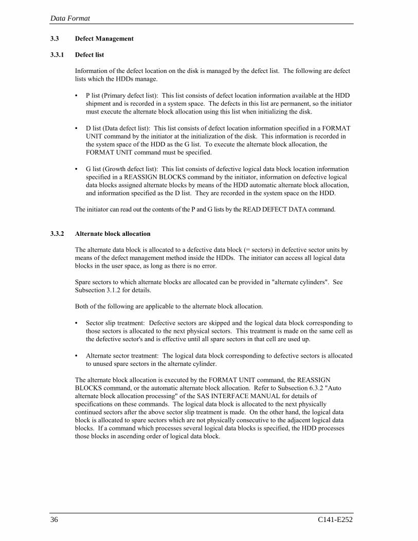
(1) Alternate block allocation during FORMAT UNIT command execution
When the FORMAT UNIT command is specified, the allocation of the alternate block to those defective sectors included in the defect list (P, G, or D) is continued until all spare sectors in the same cell are used up. When they are used up, unused spare sectors in the alternate cylinder are allocated to the defective sectors that follow the sector by means of alternate sector treatment. Figure 3.7 is examples of the alternate block allocation during the FORMAT UNIT command execution.
Figure 3.7 Alternate block allocation by FORMAT UNIT command
During FORMAT UNIT command, alternate block allocation is conducted in following cases:
1) Unrecovered write offtrack condition during a media write
2) Uncorrectable Data Error during a media read (certification) *1 If above errors are detected during FORMAT UNIT command, the HDDs allocate the alternate
block(s) to the defective data blocks. Reassign procedure itself is the same as one in REASSIGN BLOCKS command.
: Unused spare sector
: Defective sector
: n represents a logical data block number
Data Format
38 C141-E252
*1 Certification is permitted when DCRT flag is cleared (DCRT flag=0) in FORMAT UNIT command. The HDDs check all initialized logical data blocks by reading them out after the above alternate block allocation is made to initialize (format) the disk.
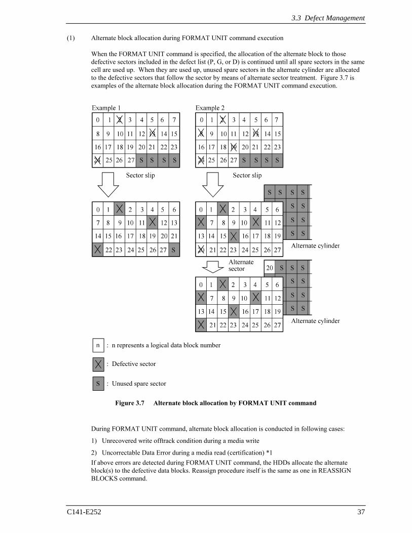
(2) Alternate block allocation by REASSIGN BLOCKS command
When the REASSIGN BLOCKS command is specified, the alternate block is allocated to the defective logical data block specified by the initiator by means of alternate sector treatment. The alternate block is allocated to unused spare sectors in the alternate cylinder.
Figure 3.8 is examples of the alternate block allocation by the REASSIGN BLOCKS command.
: Unused spare sector
Example Reassign: Block 16
: Defective sector
: n represents a logical data block number
Figure 3.8 Alternate block allocation by REASSIGN BLOCKS command
3.3 Defect Management
C141-E252 39
(3) Automatic alternate block allocation • Automatic alternate block allocation at read operation
If the ARRE flag in the MODE SELECT parameter permits the automatic alternate block allocation, the HDDs automatically execute the alternate block allocation and data duplication on the defective data block detected during the READ or READ EXTENDED command. This allocation method is the same as with the REASSIGN BLOCKS command (alternate sector treatment).
• Automatic alternate block allocation at write operation
If AWRE flag in the MODE SELECT parameter permits the automatic alternate block allocation, the HDDs execute two kinds of automatic alternate processing during WRITE command processing as described below:
Type 1 (Reassignment of Uncorrectable Read Error sector)
1) Commands to be applied - WRITE - WRITE EXTEND - WRITE at executing WRITE AND VERIFY
2) Application requirements When any of the above commands is issued to LBA registered in the uncorrectable error log of the READ command (LBA log of uncorrectable error while the READ command is executed), the AWRE processing is applied.
3) AWRE processing The following processings are performed when the LBA matches the one in the uncorrectable error log:
a) Primary media check - Creates an uncorrectable error pattern (invalid LBA pattern) in the position of the error
LBA, repeats the primary media check up to three times. If the error still occurs after the check repeated three times, it is judged to be defective. Then, it performs the alternate processing.
b) Alternate processing - Alternate media check
Writes the data that causes an unrecoverable error into the alternate block, and performs the media check. (If the alternate block is a defective sector, the block is registered to the G list, another alternate block is allocated.)
c) SA and defect map update processing (on alternate side)
When an error occurs in the alternate processing, this WRITE command terminates with error. When the alternate processing normally terminates, the WRITE command is executed.
Data Format
40 C141-E252
Type 2 (Reassignment of write fail sector)
1) Commands to be applied - WRITE - WRITE EXTENDED - FORMAT UNIT - WRITE at executing WRITE AND VERIFY
2) Application requirements / processing When WRITE/WRITE EXTENDED command detects any Servo error (e.g. Write offtrack error)
and cannot be recovered within pre-determined retry number (specified in Mode Parameter). For the sectors around defective Servo, alternate blocks are allocated and the data of this WRITE commands are re-written.
Sectors to be made AWRE shall be following: - the sector where the error occurs and the latter sectors and, - the sectors whose data are logically continual and stored in Cache, - the sectors which will be processed in this Write command and, - the sectors which locate between erroneous Servo -1 and +1 (including Split sector)
This function is also applied for the sector that has already been re-assigned. Remark: When a write protection is prohibited through the setting terminal, the auto alternate block
allocation processing specification is disabled.
Automatic alternate block allocation is made up to the following quantities during the execution of one command:
ARRE = Twice
AWRE (Type 1) = Eight times
AWRE (Type 2) = Maximum number which can be processed within the recovery time limit
If more than the above mentioned defective block is detected, the alternate block assignment processing for the first defective block is executed but the alternate block assignment processing for the second one is not executed and the command being executed terminates. However, the initiator can recover the twice error by issuing the same command again.
When an error is detected in a data block in the data area, recovery data is rewritten and verified in automatic alternate block allocation during the execution of the READ or READ EXTENDED command. Alternate block allocation will not be made for the data block if recovery is successful.
Example: Even if the data error which is recoverable by the WRITE LONG command is simulated, automatic alternate block allocation will not be made for the data block.
C141-E252 41
CHAPTER 4 Installation Requirements
4.1 Mounting Requirements
4.2 Power Supply Requirements
4.3 Connection Requirements
This chapter describes the environmental, mounting, power supply, and connection requirements. 4.1 Mounting Requirements
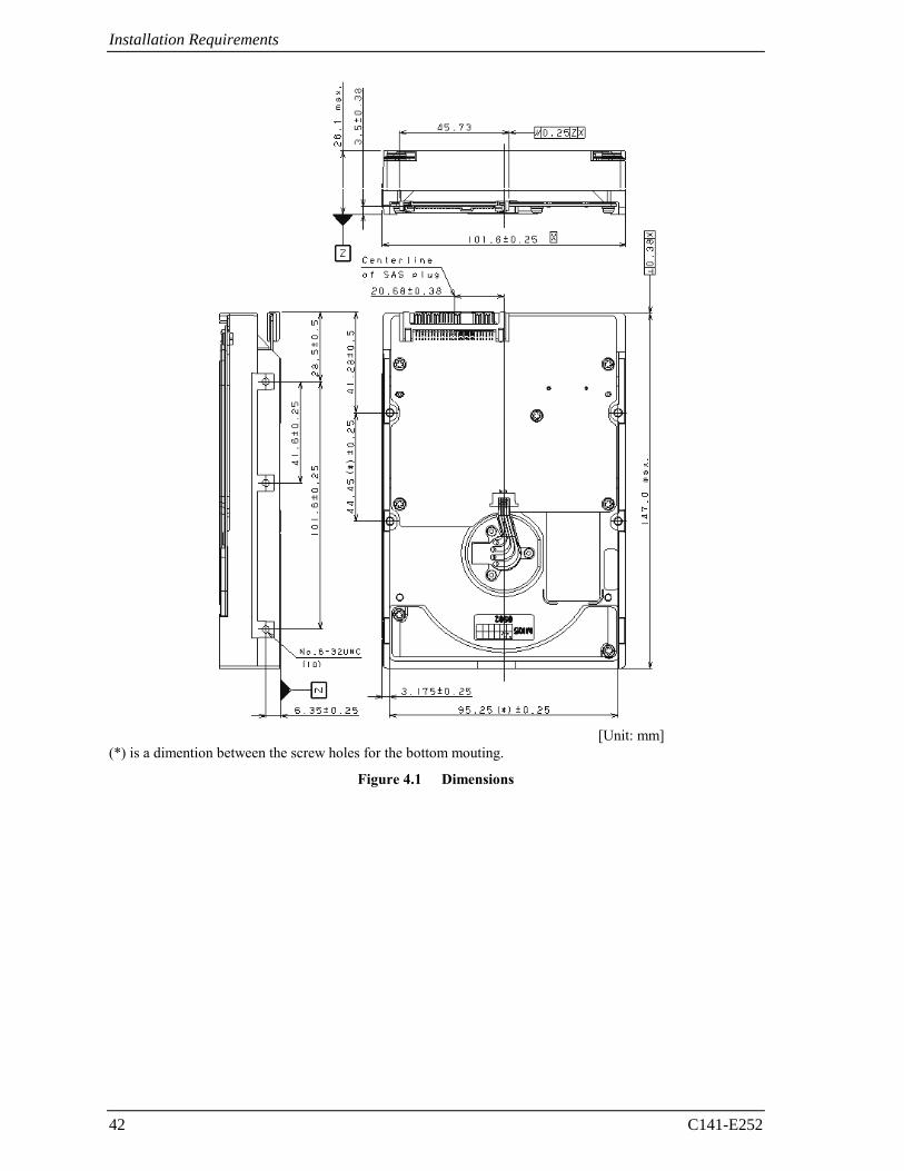
4.1.1 Dimensions
Figures 4.1 show the dimensions of the HDDs and the location of the mounting screw holes.
Installation Requirements
42 C141-E252
[Unit: mm]
(*) is a dimention between the screw holes for the bottom mouting.
Figure 4.1 Dimensions
4.1 Mounting Requirements
C141-E252 43
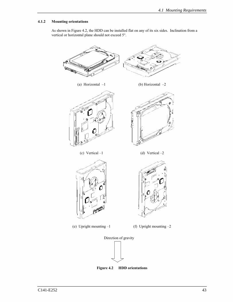
4.1.2 Mounting orientations
As shown in Figure 4.2, the HDD can be installed flat on any of its six sides. Inclination from a vertical or horizontal plane should not exceed 5°.
(a) Horizontal –1 (b) Horizontal –2
(c) Vertical –1 (d) Vertical –2
(e) Upright mounting –1 (f) Upright mounting –2
Figure 4.2 HDD orientations
Direction of gravity
Installation Requirements
44 C141-E252
4.1.3 Notes on mounting
Damage
Never remove any labels from the HDD or deface them in any way.
(1) Mounting screw
Use No.6-32UNC
(2) Mounting frame structure
Special attention must be given to mount the HDDs as follows.
a) Use the frame with an embossed structure, or the like. Mount the HDDs with making a gap of 2.5 mm or more between the HDDs and the frame of the system.
b) As shown in Figure 4.3, the inward projection of the screw from the HDD frame wall at the corner must be 4.5 mm ±0.8 mm.
c) Tightening torque of screw must be secured with 0.59 N·m (6 kgf·cm) ±12%.
d) Impact caused by the electric screwdriver must be within the HDD specifications.
e) Must be handled on an anti-static mat.
Figure 4.3 Mounting frame structure example
4.1 Mounting Requirements
C141-E252 45
(3) Limitation of side-mounting
Mount the HDDs using the 4 screw holes at the both ends on the both sides as shown in Figure 4.4. Do not use the center hole by itself.
In case of using the center hole, it must be used in combination with 2 holes on both ends. (Total 6 screws for 6 holes enclosed)
Figure 4.4 Limitation of side-mounting
(4) Limitation of bottom-mounting
Use all 4 mounting holes on the bottom face.
Installation Requirements
46 C141-E252
(5) Environmental temperature
Temperature condition at installed in a cabinet is indicated with ambient temperature measured 30 mm from the HDD. At designing the system cabinet, consider following points.
• Make a suitable air flow so that the DE surface temperature never exceed 60°C.
• Cool the PCBA side especially with air circulation inside the cabinet. Confirm the cooling effect by measuring the surface temperature of specific ICs and the DE. These measurement results must satisfy the temperature condition listed in Table 4.1.
• Keep the DE surface temperature at 50°C or below to meet the condition for assuring an MTBF of 1,400,000 hours. An air flow of 0.5 m/s or more is required at ambient temperature 30°C.
Table 4.1 Surface temperature check point and maximum temperature
No. Measurement point Maximum temperature
1 DE Surface 60°C
2 Read channel LSI 82°C
3 VCM/SPM Driver 100°C
4 HDC 97°C
5 MPU 94°C
Figure 4.5 Surface temperature measurement points
4.1 Mounting Requirements
C141-E252 47
(6) External magnetic field
The HDD should not be installed near the ferromagnetic body like a speaker to avoid the influence of the external magnetic field.
(7) Leak magnetic flux
The HDDs use a high performance magnet to achieve a high speed seek. Therefore, a leak magnetic flux at surface of the HDDs are large. Mount the HDDs so that the leak magnetic flux does not affect to near equipment.
Installation Requirements
48 C141-E252
4.2 Power Supply Requirements
(1) Allowable input voltage and current
The power supply input voltage measured at the power supply connector pin of the HDDs (receiving end) must satisfy the requirement given in Subsection 2.1.3. (For other requirements, see Items (4) and (5) below.)
(2) Current waveform (reference)
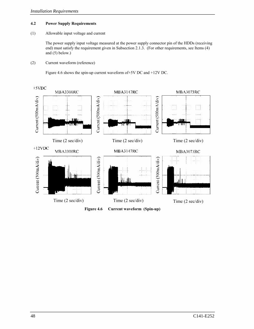
Figure 4.6 shows the spin-up current waveform of+5V DC and +12V DC.
Time (2 sec/div) Time (2 sec/div) Time (2 sec/div)
Time (2 sec/div) Time (2 sec/div) Time (2 sec/div) Figure 4.6 Current waveform (Spin-up)
4.2 Power Supply Requirements
C141-E252 49
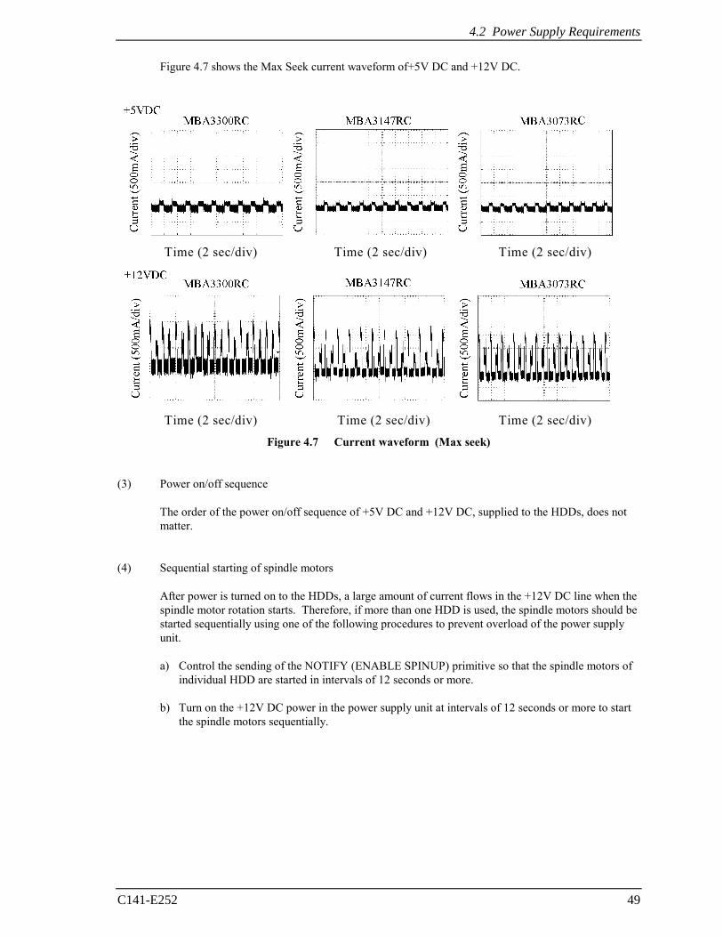
Figure 4.7 shows the Max Seek current waveform of+5V DC and +12V DC.
Time (2 sec/div) Time (2 sec/div) Time (2 sec/div)
Time (2 sec/div) Time (2 sec/div) Time (2 sec/div) Figure 4.7 Current waveform (Max seek)
(3) Power on/off sequence
The order of the power on/off sequence of +5V DC and +12V DC, supplied to the HDDs, does not matter.
(4) Sequential starting of spindle motors
After power is turned on to the HDDs, a large amount of current flows in the +12V DC line when the spindle motor rotation starts. Therefore, if more than one HDD is used, the spindle motors should be started sequentially using one of the following procedures to prevent overload of the power supply unit.
a) Control the sending of the NOTIFY (ENABLE SPINUP) primitive so that the spindle motors of individual HDD are started in intervals of 12 seconds or more.
b) Turn on the +12V DC power in the power supply unit at intervals of 12 seconds or more to start
the spindle motors sequentially.
Installation Requirements
50 C141-E252
(5) Noise filter
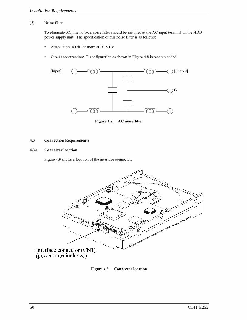
To eliminate AC line noise, a noise filter should be installed at the AC input terminal on the HDD power supply unit. The specification of this noise filter is as follows:
• Attenuation: 40 dB or more at 10 MHz
• Circuit construction: T-configuration as shown in Figure 4.8 is recommended.
Figure 4.8 AC noise filter
4.3 Connection Requirements
4.3.1 Connector location
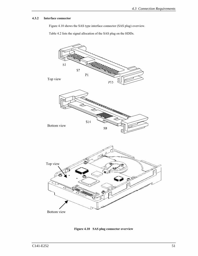
Figure 4.9 shows a location of the interface connector.
Figure 4.9 Connector location
4.3 Connection Requirements
C141-E252 51
4.3.2 Interface connector
Figure 4.10 shows the SAS type interface connector (SAS plug) overview. Table 4.2 lists the signal allocation of the SAS plug on the HDDs.
Figure 4.10 SAS plug connector overview
Top view
Bottom view
Top view
Bottom view
Installation Requirements
52 C141-E252
Table 4.2 Interface connector (SAS plug) signal allocation:CN1
Pin No. Signal Description
S1 GND GND for SAS Primary Port
S2 RP+ SAS Primary Port Receive (positive) signal
S3 RP- SAS Primary Port Receive (negative) signal
S4 GND GND for SAS Primary Port
S5 TP- SAS Primary Port Transmit (negative) signal
S6 TP+ SAS Primary Port Transmit (positive) signal
S7 GND GND for SAS Primary Port
S8 GND GND for SAS Secondary Port
S9 RS+ SAS Secondary Port Receive (positive) signal
S10 RS- SAS Secondary Port Receive (negative) signal
S11 GND GND for SAS Secondary Port
S12 TS- SAS Secondary Port Transmit (negative) signal
S13 TS+ SAS Secondary Port Transmit (positive) signal
S14 GND GND for SAS Secondary Port
P1 (*1) Reserved (not used) Not used
P2 (*1) Reserved (not used) Not used
P3 (*1) Reserved (not used) Not used
P4 GND GROUND
P5 GND GROUND
P6 GND GROUND
P7 +5V-Charge Pre-charge pin for +5V
P8 +5V +5V power supply input
P9 +5V +5V power supply input
P10 GND GROUND
P11 READY LED READY LED output
P12 GND GROUND
P13 +12V-Charge Pre-charge pin for +12V
P14 +12V +12V power supply input
P15 +12V +12V power supply input (*1) P1 to P3 are 3.3V power supply input and pre-charge signals, and not used on MBA3300RC,
MBA3147RC, and MBA3073RC.
4.3 Connection Requirements
C141-E252 53
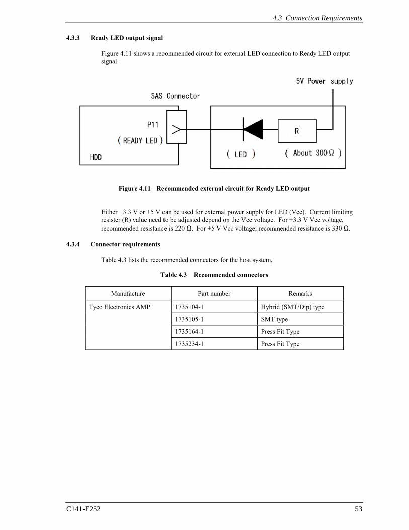
4.3.3 Ready LED output signal
Figure 4.11 shows a recommended circuit for external LED connection to Ready LED output signal.
Figure 4.11 Recommended external circuit for Ready LED output
Either +3.3 V or +5 V can be used for external power supply for LED (Vcc). Current limiting
resister (R) value need to be adjusted depend on the Vcc voltage. For +3.3 V Vcc voltage, recommended resistance is 220 Ω. For +5 V Vcc voltage, recommended resistance is 330 Ω.
4.3.4 Connector requirements
Table 4.3 lists the recommended connectors for the host system.
Table 4.3 Recommended connectors
Manufacture Part number Remarks
1735104-1 Hybrid (SMT/Dip) type
1735105-1 SMT type
1735164-1 Press Fit Type
Tyco Electronics AMP
1735234-1 Press Fit Type

This page is intentionally left blank.
C141-E252 55
CHAPTER 5 Installation
5.1 Notes on Handling HDDs
5.2 Setting
5.3 Mounting HDDs
5.4 Checking Operation after Installation and Preparing the HDDs for Use
5.5 Dismounting HDDs
This chapter describes the notes on handling HDDs, setting, mounting HDDs, confirming HDD operations after installation and preparation for use, and dismounting HDDs. 5.1 Notes on Handling HDDs
The items listed in the specifications in Table 2.3 must be strictly observed.
(1) General notes
a) Do not give the HDD shocks or vibrations exceeding the value defined in the specifications because it may cause critical damage to the HDD. Especially be careful when unpacking.
b) Do not leave the HDD in a dirty or contaminated environment.
c) Since static discharge may destroy the CMOS semiconductors in the HDD, note the following
after unpacking:
• Use an antistatic mat and body grounding when handling the HDD. • Hold the DE when handling the HDD. Do not touch PCAs except for setting.
High temperature
To prevent injury, never touch the HDD while it is hot. The DE and LSI become hot during operation and remain hot immediately after turning off the power.
Installation
56 C141-E252
(2) Unpackaging
a) Use a flat work area. Check that the "This Side Up" sign side is up. Handle the package on soft material such as a rubber mat, not on hard material such as a desk.
b) Be careful not to give excess pressure to the internal unit when removing cushions.
c) Be careful not to give excess pressure to the PCBA and interface connector when removing the
HDD from the Fcell (Fig. 6.2).
d) Do not remove any labels from the HDD. Never open the DE for any reason.
(3) Installation/removal/replacement
a) Do not move the HDD when power is turned on or until the HDD completely stops (for 30 seconds) after power is turned off.
b) Place and keep removed screws and other parts where they will not get lost or damaged. c) Keep a record of all maintenance work for replacing.
(4) Packaging
a) Store the HDD in the antistatic case (Fcell). b) It is recommended to use the same cushions and packages as those at delivery. (For details, see
Section 6.5.) If those at delivery cannot be used, use a package with shock absorption so that the HDD is free from direct shocks. In this case, fully protect the PCBA and interface connector so that they are not damaged.
(5) Delivery
a) When delivering the HDD, provide packaging and do not turn it over. b) Minimize the delivery distance after unpacking and avoid shocks and vibrations with cushions.
For the carrying direction at delivery, use one of the mount allowable directions in Subsection 4.1.2.
(6) Storage
a) Provide moistureproof packaging for storage. b) The storage environment must satisfy the requirements specified in Subsection 2.1.3 when the
HDD is not operating. c) To prevent condensation, avoid sudden changes in temperature.
5.2 Setting
C141-E252 57
5.2 Setting
5.2.1 Port Address
Every device that uses the SAS interface has a unique SAS address, and commands use an SAS address to identify each device for I/O operations. Every HDD is assigned a unique SAS address before shipment from the factory, so setting of an address is not required before the HDDs are used.
5.3 Mounting HDDs
5.3.1 Mounting procedures
Since mounting the HDD depends on the system cabinet structure, determine the work procedures considering the requirements specific to each system. The general mounting method and items to be checked are shown below.
See Section 4.1 for the details of requirements for installing the HDDs.
1) With a system to which an external operator panel is mounted, if it is difficult to access the connector after the HDD is mounted on the system cabinet, connect the external operator panel cable before mounting the HDD.
2) Fix the HDD in the system cabinet with four mounting screws as follows:
• The HDD has 10 mounting holes (both sides: 3 × 2, bottom: 4). Fix the HDD by using
four mounting holes of both sides of the HDD or the bottom.
• Use mounting screws of which lengths inside the HDD are 5.0 mm ±0.5 mm when the screws are tightened (see Figure 4.3).
• When mounting the HDD, be careful not to damage parts on the PCBA.
3) Confirm the DE is not touching the frame on the system side excluding the screw installing part after tightening the screws. At least 2.5mm of clearance is required between the DE and the frame. (indicated in Figure 4.3)
4) When using an electric screwdriver, use the screwdriver that does not apply a force on the HDD
that would exceed the HDD specifications.
Installation
58 C141-E252
5.4 Checking Operation after Installation and Preparing the HDDs for Use
5.4.1 Checking initial operation
The procedure for verifying operation after power-on is explained below.
(1) Initial diagnosis at the time of power-on:
a) When the HDDs are turned on, the LED blinks and the HDDs perform the initial self-diagnosis (controller hardware diagnosis).
b) When the SAS protocol controller diagnosis is completed normally, the HDDs start the LINK
RESET sequence defined by the SAS protocol to establish synchronization with the connected SAS devices (e.g., the host system).
c) When the initial diagnosis is completed normally, the HDDs can respond to commands from the
host. (2) Verifying interface connection:
When verification of initial operation after power-on is completed normally, the host system checks whether the HDD connection to the interface is normal. The procedure for this check depends on the host system configuration. The following is a general check procedure:
a) Confirm that the transfer rate and HDD SAS addresses can be recognized during the LINK RESET sequence.
b) Issue the INQUIRY, WRITE BUFFER, and READ BUFFER commands to verify that data is
received and transmitted normally in the interface. (3) Verifying HDD operation :
When the LINK RESET sequence has completed, the host system can issue a spindle motor start instruction and check whether the HDD is ready to operate.
a) The host system instructs the spindle motor to start by sending the NOTIFY (ENABLE SPINUP) primitive to the HDD.
b) The HDDs do not start the motor until the NOTIFY (ENABLE SPINUP) primitive is issued.
c) The HDD enters the READY state within about 60 seconds after the NOTIFY (ENABLE
SPINUP) primitive is issued.
d) The LED blinks (flashes on and off every 0.5 seconds) while the motor is running.
e) The LED remains lit when the HDDs enter the READY state. The host system can use the TEST UNIT READY command to confirm that the HDDs are in the READY state.
(4) Responses to operation errors :
a) Confirm again that connectors are securely attached to cables.
b) Check whether the supply voltage is supplied normally. (Measure the voltage at the power connectors of the HDDs.)
5.4 Checking Operation after Installation and Preparing the HDDs for Use
C141-E252 59
c) Issue the REQUEST SENSE command to collect sense data. When sense data has been collected successfully, perform an analysis to check for recoverable errors, and retry operations for recovery from any such errors.
(5) Checking at abnormal end
When sense data can be obtained, analyze the sense data and retry recovery for a recoverable error. Refer to Chapter 6 "Sense Data and Error Recovery Method" of the SAS INTERFACE MANUAL for further details.
5.4.2 Formatting
Since the HDD is formatted with a specific (default) data format for each model (part number) when shipped from the factory, the disk need not be formatted (initialized) when it is installed in the system.
However, when the system needs data attributes different from the default format, all sides of the disk must be formatted (initialized) according to the procedures below.
The user can change the following data attributes at initialization:
• Logical data block length • Number of logical data blocks in the user space
This section outlines the formatting at installation. Refer to Subsection 4.1.4 "MODE
SELECT (15)", 4.1.5 "MODE SELECT EXTENDED (55)", 4.3.1 "FORMAT UNIT (04)", and Chapter 7 "Disk Media Management" of the SAS INTERFACE MANUAL for further details.
(1) MODE SELECT/MODE SELECT EXTENDED command
Specify the format attributes on the disk with the MODE SELECT or MODE SELECT EXTENDED command. The parameters are as follows.
a. Block descriptor
Specify the size (byte length) of the logical data block in the "data block length" field. To
explicitly specify the number of logical data blocks, specify the number in the "number of data blocks" field. Otherwise, specify 0 in "number of data blocks" field. In this case, the currently set value is used.
b. Format parameter (page code = 3)
Specify the number of spare sectors for each cell in the "alternate sectors/zone" field (cannot be
changed).

Installation
60 C141-E252
(2) FORMAT UNIT command
Initialize entire recording surface of the disk with the FORMAT UNIT command. The FORMAT UNIT command initializes entire surface of the disk using the P lists, verifies data blocks after initialization, and allocates an alternate block for a defect block detected with verification. With initialization, the pattern specified with the initialization data pattern field is written into all bytes of all logical data blocks. Only the position information of defect blocks detected with verification is registered in the G list. The specifications are as follows:
a. Specifying CDB
Specify 0 for the "FmtData" bit and the "CmpLst" bit on CDB, 000 for the "Defect List Format"
field, and data pattern written into the data block at initialization for the "initializing data pattern" field.
b. Format parameter
When the values in step a. are specified with CDB, the format parameter is not needed.
5.4 Checking Operation after Installation and Preparing the HDDs for Use
C141-E252 61
5.4.3 Setting parameters
The user can specify the optimal operation mode for the user system environments by setting the following parameters with the MODE SELECT or MODE SELECT EXTENDED command:
• Error recovery parameter • Caching parameter • Control mode parameter
With the MODE SELECT or MODE SELECT EXTENDED command, specify 1 for the "SP" bit on CDB to save the specified parameter value on the disk. This enables the HDDs to operate by using the parameter value set by the user when power is turned on again.
When the parameters are not set or saved with the MODE SELECT or MODE SELECT EXTENDED command, the HDDs set the default values for parameters and operates when power is turned on or after reset. Although the HDD operations are assured with the default values, the operations are not always optimal for the system. To obtain the best performance, set the parameters in consideration of the system requirements specific to the user.
This section outlines the parameter setting procedures. Refer to Subsection 4.1.4 "MODE SELECT (15)", 4.1.5 "MODE SELECT EXTENDED (55)" of the SAS INTERFACE MANUAL for further details of the MODE SELECT and MODE SELECT EXTENDED commands and specifying the parameters.
1. At factory shipment of the HDDs, the saving operation for the MODE SELECT parameter is not executed. So, if the user does not set parameters, the HDDs operates according to the default value of each parameter
2. The MODE SELECT parameter is not saved for each initiator ID but as the common parameter for all initiator. In the multi- initiator system, parameter setting cannot be changed for each initiator.
3. Once parameters are saved, the saved value is effective as long as next saving operation is executed from the initiator. For example, even if the initialization of the disk is performed by the FORMAT UNIT command, the saved value of parameters described in this section is not affected.
4. When the HDDs, to which the saving operation has been executed on a system, are connected to another system, the user must pay attention to that the HDDs operate according to the saved parameter value if the saving operation is not executed at installation.
5. The saved value of the MODE SELECT parameter is assumed as the initial value of each parameter after the power-on, the RESET condition.. The initiator can change the parameter value temporary (actively) at any timing by issuing the MODE SELECT or MODE SELECT EXTENDED command with specifying "0" to the SP bit in the CDB.
Installation
62 C141-E252
(1) Error recovery parameters The following parameters are used to control operations such as HDD internal error recovery:
a. Read/write error recovery parameters (page code = 1)
Parameter Default value
• AWRE: • ARRE: • TB: • EER: • PER: • DCR:
Automatic alternate block allocation at Write operation Automatic alternate block allocation at read operation Uncorrectable data transfer to the initiator Immediate correction of correctable error Report of recovered error Suppression of ECC error correction
1 (enabled)
1 (enabled)
0 (disabled) 1 (enabled) 0 (disabled)
0 (Correction is enabled.)
• RETRY COUNT AT READ OPERATION • RETRY COUNT AT WRITE OPERATION • RECOVERY TIME LIMIT
63 63
30 sec
b. Verify error recovery parameters (page code = 7)
Parameter Default value
• ERR: • PER: • DTE: • DCR:
Immediate correction of recoverable error Report of recovered error Stop of command processing at successful error recovery Suppression of ECC error correction
1 (enabled) 0 (disabled)
0 (Processing is continued.)
0 (Correction is enabled.)
• RETRY COUNT AT VERIFICATION 63
c. Additional error recovery parameters (page code = 21)
Parameter Default value
• Retry count at seek error 15
Notes:
1. The user can arbitrarily specify the following parameters according to the system requirements:
• ARRE • AWRE • TB • PER
2. The user also can arbitrarily specify parameters other than the above. However, it is recommended to use the default setting in normal operations.
5.4 Checking Operation after Installation and Preparing the HDDs for Use
C141-E252 63
(2) Caching parameters (page code = 8)
The following parameters are used to optimize HDD Read-Ahead caching operations under the system environments. Refer to Chapter 3 "Data Buffer Management" of the SAS INTERFACE MANUAL for further details.
Parameter Default value
• IC: Initiator control 0 (HDD-specific control (page
cache))
• RCD: Disabling Read-Ahead caching operations 0 (enabled)
• WCE: Write Cache Enable 1 (enabled)
• MF: Specifying the multipliers of "MINIMUM PRE-FETCH" and "MAXIMUM PRE-FETCH" parameters
0 (Specifying absolute value)
• DISC: Prefetch operation after track switching during prefetching
1 (enabled)
• DISABLE PRE-FETCH TRANSFER LENGTH X'FFFF'
• MINIMUM PRE-FETCH X'0000'
• MAXIMUM PRE-FETCH X'0000'
• MAXIMUM PRE-FETCH CEILING X'FFFF'
• NUMBER OF CACHE SEGMENTS X'08'
Notes:
1. When Read-Ahead caching operations are disabled by the caching parameter, these parameter settings have no meaning except write cache feature.
2. Determine the parameters in consideration of how the system accesses the disk. When the access form is not determined uniquely because of the processing method, the parameters can be re-set actively.
3. For sequential access, the effective access rate can be increased by enabling Read-Ahead caching operations and Write Cache feature.
(3) Control mode parameters (page code = A)
The following parameters are used to control the tagged queuing and error logging.
a. Control mode parameters
Parameter Default value
• QUEUE ALGORITHM MODIFIER 0 (Execution sequence of read/write commands is
optimized.)
• QErr: Resume or abort remaining suspended commands after sense pending state
0 (command is resumed)
Installation
64 C141-E252
(4) Port control parameters
The following parameters are used to control the ready LED signal behavior.
Parameter Default value
• READY LED MEANING 0 (LED is on when HDD is ready)
5.5 Dismounting HDDs
Since the method and procedure for dismounting the HDD, etc. depends on the locker structure of the system, etc., the work procedure must be determined in consideration of the requirements specific to the system. This section describes the general procedure and notes on dismounting the HDD.
High temperature To prevent injury, never touch the HDD while it is hot. The DE and LSI become hot during operation and remain hot immediately after turning off the power.
Damage 1. When dismounting the HDD which is mounted on the system while power is
supplied to it. 1) Stop the spindle motor by a START/STOP_UNIT command. It takes about
30 seconds for the spindle motor to stop completely. 2) Then, dismount the HDD using the drive mounting/dismounting
mechanism, etc. of the system. When removing the HDD, avoid exposing it to shock or vibration. Just in case, stop dismounting once when SAS connector breaks off contact and wait until the spindle motor stops (about 30 seconds.).
2. When dismounting the HDD which is mounted on the system while power is
not supplied to it. • Dismount the HDD using the HDD mounting/dismounting mechanism,
etc. of the system. When removing the HDD, avoid exposing it to shock or vibration.
3. When storing or transporting the HDD, put it in the antistatic case (Fcell) (refer to Section 5.1 and 6.5).
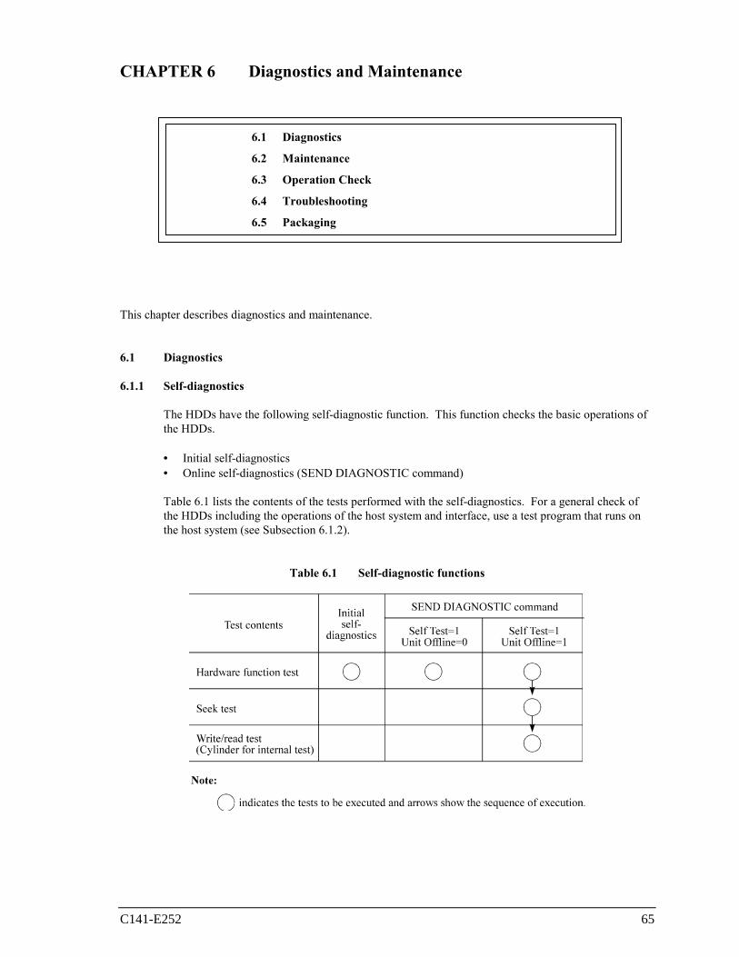
C141-E252 65
CHAPTER 6 Diagnostics and Maintenance
6.1 Diagnostics
6.2 Maintenance
6.3 Operation Check
6.4 Troubleshooting
6.5 Packaging
This chapter describes diagnostics and maintenance. 6.1 Diagnostics
6.1.1 Self-diagnostics
The HDDs have the following self-diagnostic function. This function checks the basic operations of the HDDs.
• Initial self-diagnostics • Online self-diagnostics (SEND DIAGNOSTIC command)
Table 6.1 lists the contents of the tests performed with the self-diagnostics. For a general check of
the HDDs including the operations of the host system and interface, use a test program that runs on the host system (see Subsection 6.1.2).
Table 6.1 Self-diagnostic functions
Diagnostics and Maintenance
66 C141-E252
Brief test contents of self-diagnostics are as follows.
a. Hardware function test
This test checks the basic operation of the controller section, and contains following test.
• RAM (microcode is stored) • Peripheral circuits of microprocessor (MPU) • Data buffer
b. Seek test
This test checks the positioning operation of the HDD using several seek modes (2 points seek, 1
position sequential seek, etc.). The positioning operation is regarded as success when the seek operation to the target cylinder is completed.
c. Write/read test
This test checks the write/read function by using the internal test space of the HDD.
(1) Initial self-diagnostics
When the HDDs are turned on, they run the initial self-diagnostics. The initial self-diagnostics test the basic operations of hardware functions.
If the initial self-diagnostics detect an error, the LED on the HDD blinks (at 0.4-second intervals). The HDDs in this state post the CHECK CONDITION status to all I/O operation requests except the REQUEST SENSE command. The initiator can collect sense data when the CHECK CONDITION status is posted.
Sense data contains detailed information on the error detected by the initial self-diagnostics.
When sense data has been collected after the CHECK CONDITION status has been posted, the CHECK CONDITION status continues and the LED keeps blinking. This status can be cleared only when the HDDs are turned off and turned on again. When the status is cleared, the HDDs run the initial self-diagnostics again.
The HDDs do not reply to requests from the host system for a maximum of 2 seconds after the start of the initial self-diagnostics. Thereafter, the HDDs can accept I/O operation requests normally, but any received command, except commands that are executable even in the not ready state, is terminated with the CHECK CONDITION status until the spindle motor reaches the normal rotational speed and the HDDs become ready. The commands that are executable even in the not ready state are executed in parallel with the initial self-diagnostics, or they are queued by the command queuing feature and executed when the initial self-diagnostics is completed.
If the initial self-diagnostics detect an error, the CHECK CONDITION status is posted for all of the commands received and queued during the initial self-diagnostics.
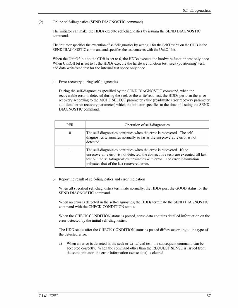
6.1 Diagnostics
C141-E252 67
(2) Online self-diagnostics (SEND DIAGNOSTIC command)
The initiator can make the HDDs execute self-diagnostics by issuing the SEND DIAGNOSTIC command.
The initiator specifies the execution of self-diagnostics by setting 1 for the SelfTest bit on the CDB in the SEND DIAGNOSTIC command and specifies the test contents with the UnitOfl bit.
When the UnitOfl bit on the CDB is set to 0, the HDDs execute the hardware function test only once. When UnitOfl bit is set to 1, the HDDs execute the hardware function test, seek (positioning) test, and data write/read test for the internal test space only once.
a. Error recovery during self-diagnostics
During the self-diagnostics specified by the SEND DIAGNOSTIC command, when the
recoverable error is detected during the seek or the write/read test, the HDDs perform the error recovery according to the MODE SELECT parameter value (read/write error recovery parameter, additional error recovery parameter) which the initiator specifies at the time of issuing the SEND DIAGNOSTIC command.
PER Operation of self-diagnostics
0 The self-diagnostics continues when the error is recovered. The self-diagnostics terminates normally so far as the unrecoverable error is not detected.
1 The self-diagnostics continues when the error is recovered. If the unrecoverable error is not detected, the consecutive tests are executed till last test but the self-diagnostics terminates with error. The error information indicates that of the last recovered error.
b. Reporting result of self-diagnostics and error indication When all specified self-diagnostics terminate normally, the HDDs post the GOOD status for the
SEND DIAGNOSTIC command.
When an error is detected in the self-diagnostics, the HDDs terminate the SEND DIAGNOSTIC command with the CHECK CONDITION status.
When the CHECK CONDITION status is posted, sense data contains detailed information on the error detected by the initial self-diagnostics.
The HDD status after the CHECK CONDITION status is posted differs according to the type of the detected error.
a) When an error is detected in the seek or write/read test, the subsequent command can be accepted correctly. When the command other than the REQUEST SENSE is issued from the same initiator, the error information (sense data) is cleared.
Diagnostics and Maintenance
68 C141-E252
b) When an error is detected in the hardware function test, the HDDs post the CHECK CONDITION status for all I/O operation request except the REQUEST SENSE command. The error status is not cleared even if the error information (sense data) is read. Only when the power is turned off or re-turned on, the status can be cleared. When this status is cleared, the HDDs execute the initial self-diagnostics again (see item (1)).
Refer to Subsection 4.4.1 "SEND DIAGNOSTIC (1D)" of the SAS INTERFACE MANUAL for further details of the command specifications.
6.1.2 Test programs
The basic operations of the HDDs themselves can be checked with the self-diagnostic function. However, to check general operations such as the host system and interface operations in a status similar to the normal operation status, a test program that runs on the host system must be used.
The structure and functions of the test program depend on the user system requirements. Generally, it is recommended to provide a general input/output test program that includes devices connected to the input/output devices on other I/O ports.
Including the following test items in the test program is recommended to test the HDD functions generally.
(1) Interface test
The operations of the data buffer on the HDDs are checked with the WRITE BUFFER and READ BUFFER commands.
(2) Basic operation test
The basic operations of the HDDs are checked by executing self-diagnosis with the SEND DIAGNOSTIC command (see Subsection 6.1.1).
(3) Random/sequential read test
The positioning (seek) operation and read operation are tested in random access and sequential access modes with the READ, READ EXTENDED, or VERIFY command.
6.2 Maintenance
C141-E252 69
6.2 Maintenance
See Section 5.1 and 6.5 for notes on packaging and handling when returning the HDD.
Data loss
Save data stored on the HDD to other media before requesting repair. Fujitsu does not assume responsibility if data is corrupted during servicing or repair.
6.2.1 Precautions
Take the following precautions to prevent injury during maintenance and troubleshooting:
High temperature
To prevent injury, never touch the HDD while it is hot. The DE and LSI become hot during operation and remain hot immediately after turning off the power.
Electrical shock
Never touch the HDDs while power-feeding.
Take the following precautions to prevent HDD damage during maintenance and troubleshooting:
Damage
• Always ground yourself with a wrist strap connected to ground before handling. ESD (Electrostatics Discharge) may cause the damage to the device.
• Never use a conductive cleaner to clean the HDDs.
• Never remove any labels from the HDD or deface them in any way.
• Never remove the PCBA.
• Never open the HDD for any reason.
Diagnostics and Maintenance
70 C141-E252
6.2.2 Maintenance requirements
(1) Preventive maintenance
Preventive maintenance is not required.
(2) Service life
See "(3) Service life," in Subsection 2.1.5.
(3) Parts that can be replaced in the field
The PCBA cannot be replaced in the field. The DE cannot be replaced in the field.
(4) Service system and repairs
Fujitsu has the service system and repair facility for the HDD. Contact Fujitsu representative to submit information for replacing or repairing the HDD. Generally, the following information must be included:
a) Model part number (P/N), revision number, serial number (S/N), and date of manufacturing b) Error status
• Date when the error occurred • System configuration • Environmental conditions (temperature, humidity, and voltage)
c) Error history
d) Error contents
• Outline of inconvenience • Issued commands and specified parameters • Sense data • Other error analysis information
6.2 Maintenance
C141-E252 71
6.2.3 Maintenance levels
If an HDD is faulty, replace the whole HDD since repair requires special tools and environment. This section explains the two maintenance levels.
(1) Field maintenance (HDD replacement)
• This replacement is done at the user's site.
• Replacement uses standard tools.
• Replacement is usually done by the user, retail dealer, distributor, or OEM engineer.
(2) Factory maintenance (parts replacement)
• This replacement can only be done by Fujitsu.
• Replacement includes maintenance training and OEM engineer support. OEM engineers usually support retail dealers and distributors.
• Replacement uses factory tools and test equipment. 6.2.4 Tools and test equipment
HDD troubleshooting and repair in the field require only standard hand tools. No special tools or test equipment are required.
This manual does not describe the factory-level tools and test equipment.
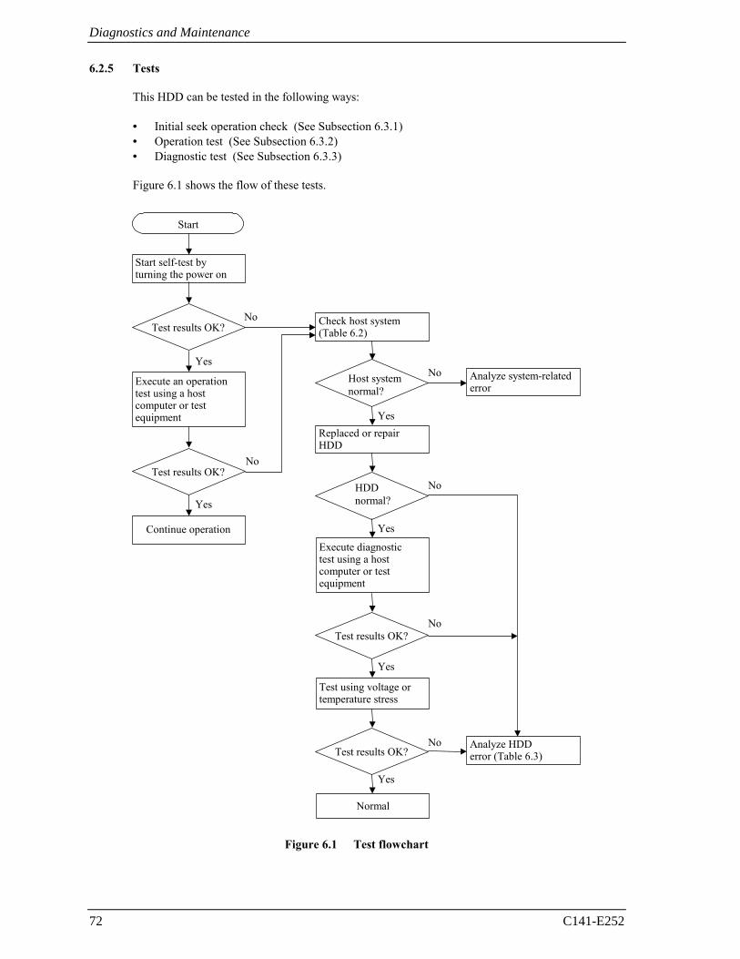
Diagnostics and Maintenance
72 C141-E252
6.2.5 Tests
This HDD can be tested in the following ways:
• Initial seek operation check (See Subsection 6.3.1) • Operation test (See Subsection 6.3.2) • Diagnostic test (See Subsection 6.3.3)
Figure 6.1 shows the flow of these tests.
Test results OK?
Start
Execute an operation test using a host computer or test equipment
Yes
No
Yes
No
Start self-test by turning the power on
Test results OK?
Continue operation
Check host system (Table 6.2)
Host system normal?
Analyze system-related error
Replaced or repair HDD
HDD normal?
Execute diagnostic test using a host computer or test equipment
Test results OK?
Test using voltage or temperature stress
Test results OK?
Normal
Analyze HDD error (Table 6.3)
Yes
Yes
No
No
Yes
No
Yes
No
Figure 6.1 Test flowchart
6.3 Operation Check
C141-E252 73
6.3 Operation Check
6.3.1 Initial seek operation check
If an error is detected during initialization by the initial seek operation check routine at power-on, the spindle motor of the HDD stops, and then the HDD becomes unusable.
For an explanation of the operation check before the initial seek, refer to the Section 5.4. 6.3.2 Operation test
While the host computer is processing data, the HDDs monitor HDD operation including data processing, command processing, and seek operations. If the HDDs detect an error, the HDDs post the error to the initiator. The initiator then posts the error to the user.
The user may detect an intermittent or nonfatal error such as abnormal noise, abnormal odor, or very slow operation.
An error posted in an operation test must be investigated. The user can replace the HDD to see whether the error was caused by the HDD.
Often, errors posted in an operation test may be caused by the host system. Possible causes include insufficient power capacity, loose cable connection, insufficient timing or insufficient mechanical play, and problems related to other systems.
If an operation error is detected by the error detection circuit of the HDD, an interrupt occurs. The interrupt is posted to the MPU on the PCBA. The MPU stops the currently processed command, and causes the CHECK CONDITION status to post the error to the initiator.
When receiving the CHECK CONDITION status, the initiaor collects detailed information via SENSE data.
To analyze the error posted in the operation test, reconstruct the conditions in which the error occurred. Then, start troubleshooting the whole host system by replacing the HDD.
6.3.3 Diagnostic test
The diagnostic test is executed to find a faulty subassembly in a faulty HDD, or to check HDD performance. This test is usually a combination of specific HDD functions or group of functions. This test may be executed using a different host computers or test equipment and away from the environment where the error first occurred.
To analyze the error posted in the diagnostic test, reconstruct the conditions in which the error occurred. Then, look for a possibly faulty subassembly or part of the HDD.
The procedures to be used in this test depend largely on the type of test equipment used, and are not covered by this manual.
Diagnostics and Maintenance
74 C141-E252
6.4 Troubleshooting
6.4.1 Outline of troubleshooting procedures
This section explains the troubleshooting procedures for HDD errors.
Depending on the maintenance level, analyze the error to detect a possibly faulty part (HDD, or HDD part).
Full-scale troubleshooting is usually required if the error cause is not known. If the error cause is clear (e.g., abnormal noise in DE or burning of the PCBA), troubleshooting is straightforward.
6.4.2 Troubleshooting with HDD replacement in the field
At this level of maintenance, we recommend replacing the HDD as a unit. If replacing the HDD rectifies the fault, return the removed HDD to Fujitsu, for test and repair. If the newly installed HDD does not rectify the fault another part of the system is faulty.
Table 6.2 summarizes system-level field troubleshooting. Troubleshooting must be done in the field, to find faulty part (HDD or system).
6.4 Troubleshooting
C141-E252 75
Table 6.2 System-level field troubleshooting
Item Recommended work
DC power level Check that the DC voltage is within the specified range (±5%).
For +5V DC, measure the voltage between pin P8 (+5V) of the interface connector and the nearest PCBA mounting screw (GND) from the interface connector, and confirm the value is from 4.75 to 5.25 VDC.
For +12V DC, measure the voltage between pin P14 (+12V) of the interface connector and the nearest PCBA mounting screw (GND) from the interface connector, and confirm the value is from 11.4 to 12.6 VDC.
Electrical noise Make sure the maximum ripple peak-to-peak value of +5V DC is within 250 mV and +12V DC is within 250 mV.
Make sure the high frequency noise (over 20 MHz) is less than 100 mVp-p.
System cables Check that all system cables are connected correctly.
System diagnostic test When possible, execute the system level diagnostic routine as explained in the host computer manual. This gives a detailed report of a possible fault.
Intermittent or nonfatal errors Check the AC voltage from the power supply. Check the DC voltage level at the power connector for the HDD.
If the AC voltage level is abnormal or there is a lot of electrical noise, notify the user of the error.
If the DC voltage level is unstable, replace the power supply unit.
If possible, replace the HDD. If replacing the HDD does not eliminate the error, the removed HDD is probably not faulty. To continue error analysis, refer to the hardware and software manuals supplied with the system.
Diagnostics and Maintenance
76 C141-E252
6.4.3 Troubleshooting at the repair site
For maintenance at this level, we recommend additional testing of the HDD and signal checking.
The sense data posted from the HDDs help with troubleshooting. This sense data makes the error type clear (functional, mechanical, or electrical error). Chapter 7 error analysis by sense data, and gives supplementary information on finding the error cause (faulty part).
Table 6.3 lists how to detect a faulty HDD subassembly. This fault finding requires a working host computer or HDD test equipment to recreate the error conditions.
If the detected error cannot be recreated in an ordinary test, HDD conditions can be changed to force the error to recur. This is done by changing the DC voltage or the ambient temperature of the HDD.
If the error does not recur with changed conditions, the HDD is not faulty. If no error occurs in the HDD test, notify the user of the test results, and find out from the user the environment conditions where the HDD is used.
Table 6.3 HDD troubleshooting
Item Recommended action
Frequent or repeated seek errors Collect sense data, and see Chapter 7.
Replace the HDD, and check that the test method is correct. If the error recurs, it is likely that the HDD is normal but the test method is incorrect.
Intermittent or nonfatal errors Replace the HDD, and check that the test method is correct. If the error recurs, it is likely that the HDD is normal but the test method is incorrect.
To check performance, change the HDD conditions by changing the voltage or temperature.
If the HDD error recurs or a possibly faulty part is found by troubleshooting, return the complete HDD to Fujitsu for repair. A media defect list must be included with the HDD returned to Fujitsu.
If the possibly faulty part is the DE, return the whole HDD to Fujitsu for repair. Also if a clear error (erroneous servo track information or noisy HDD) is detected in the DE, return the whole HDD to Fujitsu. A media defect list must be included with the HDD returned to Fujitsu.
Damage
• Never remove any labels from the HDD or deface them in any way.
• Never open the HDD for any reason. Doing so will void any warranties.
6.5 Packaging
C141-E252 77
6.4.4 Troubleshooting with parts replacement in the factory
This manual does not cover troubleshooting at the factory level.
6.4.5 Finding possibly faulty parts
Finding possibly faulty parts in the field was explained in Subsection 6.4.2. This manual does not cover finding possibly faulty parts at the factory level.
6.5 Packaging
When the HDD is returned to Fujitsu, the following methods are recommended.
6.5.1 Unitary packaging
Figure 6.2 Unitary packaging
(1) Put the HDD into FCELL.
• At this time, the connector of the HDD is directed to the hinge side of FCELL.
• The PCBA is put in the side with the material mark of FCELL.
(2) Push from two corners of FCELL on the hinge side previously, push two corners of the opening next, and lock FCELL surely.
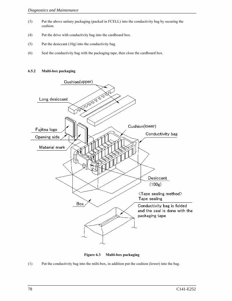
Diagnostics and Maintenance
78 C141-E252
(3) Put the above unitary packaging (packed in FCELL) into the conductivity bag by securing the cushion.
(4) Put the drive with conductivity bag into the cardboard box.
(5) Put the desiccant (10g) into the conductivity bag.
(6) Seal the conductivity bag with the packaging tape, then close the cardboard box.
6.5.2 Multi-box packaging
(upper)
(lower)
Figure 6.3 Multi-box packaging
(1) Put the conductivity bag into the milti-box, in addition put the cushion (lower) into the bag.
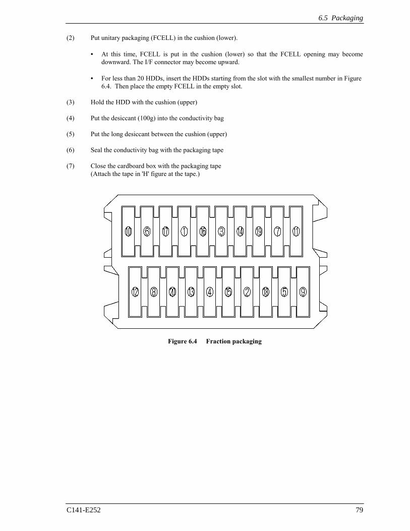
6.5 Packaging
C141-E252 79
(2) Put unitary packaging (FCELL) in the cushion (lower).
• At this time, FCELL is put in the cushion (lower) so that the FCELL opening may become downward. The I/F connector may become upward.
• For less than 20 HDDs, insert the HDDs starting from the slot with the smallest number in Figure 6.4. Then place the empty FCELL in the empty slot.
(3) Hold the HDD with the cushion (upper)
(4) Put the desiccant (100g) into the conductivity bag
(5) Put the long desiccant between the cushion (upper)
(6) Seal the conductivity bag with the packaging tape
(7) Close the cardboard box with the packaging tape (Attach the tape in 'H' figure at the tape.)
Figure 6.4 Fraction packaging

This page is intentionally left blank.
C141-E252 81
CHAPTER 7 Error Analysis
7.1 Sense Data Collection 7.2 Sense Data Analysis
This chapter explains in detail how sense data collected from an HDD is used for troubleshooting. Sense data reflects an error in the HDD, and helps with troubleshooting.
7.1 Sense Data Collection
7.1.1 Sense data
When HDDs post a CHECK CONDITION status, the current command or queued command is cleared. In such a case, the HDDs generate sense data about the command-issuing initiator. The initiator can read the sense data by reading the sense data added to the response frame of the command where an error occurred (Auto Sense function).
This HDD is equipped with sense data with a byte length of 48. Accordingly, Fujitsu recommends collecting all 48-byte sense data when the host unit collects sense data.
A sense key, additional sense code, and additional sense code qualifier, taken from various sense data are repeated. Also in this chapter, troubleshooting is performed using these three codes. Unless otherwise specified, "sense data" means the above three codes. When sense data is represented as (x-xx-xx), the leftmost x is a sense key, the middle xx is an additional sense code, and the rightmost x is an additional sense code qualifier.
7.1.2 Sense data format
Figure 7.1 shows the sense data format.
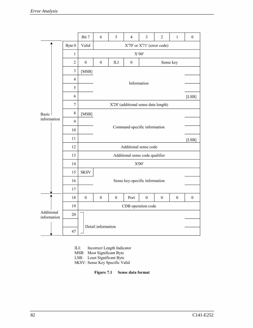
Error Analysis
82 C141-E252
Bit 7 6 5 4 3 2 1 0
Byte 0 Valid X'70' or X'71' (error code)
1 X‘00'
2 0 0 ILI 0 Sense key
3
4
5
6
7 X'28' (additional sense data length)
8
9
10
11
12 Additional sense code
13 Additional sense code qualifier
14 X'00'
15 SKSV
16 Sense key-specific information
17
18 0 0 0 Port 0 0 0 0
19 CDB operation code
20
47
ILI: Incorrect Length Indicator MSB: Most Significant Byte LSB: Least Significant Byte SKSV: Sense Key Specific Valid
Figure 7.1 Sense data format
[MSB]
Detail information
[LSB]
[LSB]
Command-specific information
Information
Additional information
Basic information
[MSB]
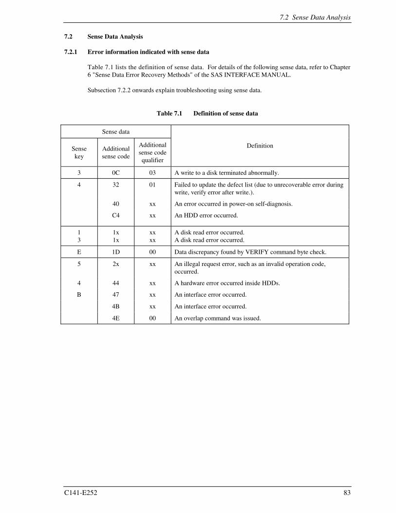
7.2 Sense Data Analysis
C141-E252 83
7.2 Sense Data Analysis
7.2.1 Error information indicated with sense data
Table 7.1 lists the definition of sense data. For details of the following sense data, refer to Chapter 6 "Sense Data Error Recovery Methods" of the SAS INTERFACE MANUAL.
Subsection 7.2.2 onwards explain troubleshooting using sense data.
Table 7.1 Definition of sense data
Sense data
Sense key
Additional sense code
Additional sense code qualifier
Definition
3 0C 03 A write to a disk terminated abnormally.
4 32 01 Failed to update the defect list (due to unrecoverable error during write, verify error after write.).
40 xx An error occurred in power-on self-diagnosis.
C4 xx An HDD error occurred.
1 3
1x 1x
xx xx
A disk read error occurred. A disk read error occurred.
E 1D 00 Data discrepancy found by VERIFY command byte check.
5 2x xx An illegal request error, such as an invalid operation code, occurred.
4 44 xx A hardware error occurred inside HDDs.
B 47 xx An interface error occurred.
4B xx An interface error occurred.
4E 00 An overlap command was issued.
Error Analysis
84 C141-E252
7.2.2 Sense data (3-0C-03), (4-32-01), (4-40-xx), (4-C4-xx), and (4-44-xx)
Sense data (3-0C-03), (4-32-01), (4-40-xx), (4-C4-xx), and (4-44-xx) indicate one of the following:
• A target sector could not be detected using the sector counter.
• A seek process overran the specified time.
• A write to a disk terminated abnormally.
• An error occurred in power-on self-diagnosis.
• An HDD error occurred.
The symptoms above are generally caused by an error in a PCBA or DE.
7.2.3 Sense data (1-1x-xx), (3-1x-xx) and (E-1D-00): Disk read error
If sense data (1-1x-xx), (3-1x-xx) or (E-1D-00) occurs frequently in a specific block of a disk, there is disk damage that was not recorded in the media defect list. In this case, assign an alternate block to the error-detected block using a REASSIGN BLOCKS command. For an explanation of the REASSIGN BLOCKS command, refer to Subsection 4.3.2 "REASSIGN BLOCKS (07)" of the SAS INTERFACE MANUAL.
If this error occurs in different blocks, a PCBA or DE is faulty.
7.2.4 Sense data (5-2x-xx), (B-47-xx), (B-4B-xx) and (B-4E-00): interface error
Sense data (5-2x-xx), (B-47-xx), (B-4B-xx) and (B-4E-00) indicates one of the following symptoms:
• An invalid or unsupported command was issued, or invalid or unsupported parameters were specified.
• An interface error occurred.
• A hardware error occurred inside HDDs.
If this error occurs, the PCBA or the interface is faulty.
C141-E252 85
Glossary
Additional Sense Code
This is a 1-byte code displayed in the sense data and is information which specifies the type of error that was detected.
CDB
Command Descriptor Block A series of data which describes commands related to input/output operations, sent from the initiator to the target.
Command
This is a command to a target to perform an input/output operation, and it is described as the CDB.
Initiator
This is an SAS device which initiates input and output operations on the SAS bus.
SAS Device
The general name given to a device which is connected to the SAS bus (input/output device, I/O controller, host adapter, expander, etc.).
SCSI
Small Computer System Interface The standardized input/output interface of the American National Standards Institute (ANSI). [Standard No.: ANSI X3. 131-1986]
Sense Data
When several items of error information are included in a command's completion status, this is information generated by the target for reporting detailed information on that status.
Sense Key
This is a 4-bit code displayed in the sense data. It contains information for classifying the type of error that was detected.
Status
This is 1 byte of information reported to the initiator by the target device when execution of each command is completed, which displays the command's completion state.
Target
This is the SAS device that executes the input/output operations initiated by the initiator.

This page is intentionally left blank.
Acronyms and Abbreviations
A H
AC Alternating Current HDC Hard Disk Controller ARRE Automatic Read Reallocation
Enabled HDD Hard Disk Drive
I AWRE Automatic Write Reallocation Enabled
ID IDentifier I/O Input/Output B
L bpi Bits Per Inch
LED Light Emitting Diode LSI Large-Scale Integration circuit C
CDB Command Descriptor Block CmpLst Complete List M CRC Cyclic Redundancy Check
MEEPRML Modified Enhanced Extended Partial Response Maximum Likelihood
CYL CYLinder
D MPU MicroProcessor Unit
D list Data Defect List MR Magnetro Resistive DC Direct Current MTBF Mean Time
Between Failure DCR Disable CoRrection DCRT Disable CeRtificaTion MTTR Mean Time To Repair DE Disk Enclosure DTE Disable Transfer on Error O
OEM Original Equipment Manufacturer
E
ECC Error Correction Code EER Enable Early Recovery P
P list Primary defect list F P/N Parts/Number
FIFO First In First Out PCBA Printed Circuit Board Assembly FmtData Format Data
PER Post ERror PLO Sync Phase Lock Oscillator
Syncronous G Gbps Gigabits per second
G list Grown defect list R
RCD Read Cache Disable RH Relative Humidity
C141-E252 87
Acronyms and Abbreviations
S
S/N Serial/Number SAS Serial Attached SCSI SCSI Small Computer System
Interface SCT SeCTor SelfTest Self Test SP Save Page SPM SPindle Motor
T
TB Transfer Block TPI Tracks Per Inch
U
UnitOfl Unit Offline
V
VCM Voice Coil Motor
W
WCE Write Cache Enable
88 C141-E252
C141-E252 89
Index
A
acoustic noise................................................... 20 actuator ............................................................ 17 additional error recovery parameter................. 62 additional sense code ....................................... 81 additional sense code qualifier......................... 81 allowable input voltage.................................... 48 alternate area.................................................... 35 alternate block allocation ................................. 36 alternate block allocation by REASSIGN
BLOCKS command ................................... 38 alternate block allocation during
FORMAT UNIT command execution ....... 37 alternate processing ......................................... 39 alternate spare area .......................................... 30 automatic alternate block allocation ................ 39 automatic alternate block reassignment ........... 15
B
basic operation test .......................................... 68 BCRC............................................................... 33 block address of user space.............................. 35 block descriptor ............................................... 59
C
cache feature .................................................... 14 caching parameter............................................ 63 checking at abnormal end ................................ 59 checking initial operation ................................ 58 checking operation after installation and
preparing HDD for use............................... 58 command queuing feature................................ 15 connection requirement ................................... 50 connector location............................................ 50 connector requirements.................................... 53 continuous block processing............................ 14 control mode parameter ................................... 63 controller circuit............................................... 17 current.............................................................. 48 current waveform....................................... 48, 49 cylinder configuration...................................... 27
D
data field .......................................................... 33 data format....................................................... 27 data security at power failure........................... 25 data space......................................................... 27 defect list.......................................................... 36
defect management .......................................... 36 defective block slipping ................................... 16 delivery ............................................................ 56 diagnosis .......................................................... 16 diagnostic ......................................................... 65 diagnostic test .................................................. 73 dimension......................................................... 41 disk................................................................... 17 dismounting HDDs .......................................... 64 dual SAS port support...................................... 14
E
ECC.................................................................. 33 environmental protection ................................. 13 environmental temperature .............................. 46 environmental/power requirement ................... 23 error analysis.................................................... 81 error information indicated with sense
data ............................................................. 83 error rate........................................................... 24 error recovery................................................... 15 error recovery during self-diagnostic............... 67 error recovery parameter.................................. 62 external magnetic field..................................... 47 eye mask .......................................................... 22
F
factory maintenance......................................... 71 field maintenance............................................. 71 finding possibly faulty part .............................. 77 format capacity ................................................ 34 format of extended sense data.......................... 82 format parameter........................................ 59, 60 FORMAT UNIT command.............................. 60 formatting ........................................................ 59 function specification....................................... 20
G
gap.................................................................... 33 general note...................................................... 55
H
hardware function test...................................... 66 hardware specification ..................................... 19 hardware structure............................................ 17 HDD replacement ............................................ 71 head.................................................................. 17 head skew......................................................... 31
Index
90 C141-E252
I
initial diagnosis at time of power-on................ 58 initial seek operation check.............................. 73 initial self-diagnostic........................................ 66 installation.................................................. 55, 56 installation requirement.................................... 41 interface connector........................................... 51 interface test ..................................................... 68 internal test space ............................................. 29
L
leak magnetic flux............................................ 47 limitation of bottom-mounting......................... 45 limitation of side-mounting.............................. 45 logical data block addressing ........................... 34
M
maintenance ..................................................... 69 maintenance level............................................. 71 maintenance requirement ................................. 70 microcode downloading................................... 16 MODE SELECT/MODE SELECT
EXTENDED command.............................. 59 model name...................................................... 19 mounting frame structure................................. 44 mounting HDDs............................................... 57 mounting orientations ...................................... 43 mounting procedure ......................................... 57 mounting requirement...................................... 41 mounting screw................................................ 44 MTBF............................................................... 24 MTTR .............................................................. 25 multi-segment data buffer ................................ 14
N
noise filter ........................................................ 50 note on handling HDDs ................................... 55 note on mounting ............................................. 44
O
online self-diagnostic ....................................... 67 operation check ................................................ 73 operation test.................................................... 73 order number.................................................... 19 outline of troubleshooting procedure ............... 74
P
packaging ................................................... 56, 77 PAD ................................................................. 33 page code ................................................... 59, 62 part replacement............................................... 71 part that can be replaced in field ...................... 70
physical sector allocation ................................. 31 PLO Sync ......................................................... 33 port address ...................................................... 57 port addressing ................................................. 18 power on/off sequence ..................................... 49 power supply requirement................................ 48 precaution......................................................... 69 preventive maintenance.................................... 70 programmable data block length...................... 15
R
random/sequential read test.............................. 68 read/write circuit .............................................. 17 read/write error recovery parameter................. 62 ready LED output signal .................................. 53 reassignment............................................... 39, 40 recommended connectors................................. 53 reliability .......................................................... 24 removal ............................................................ 56 repair ................................................................ 70 replacement ...................................................... 56 reporting result of self-diagnostic and
error indication ........................................... 67 reserve and release function ............................. 15 responses to operation errors............................ 58
S
SAS standard.................................................... 14 sector format .................................................... 32 seek test ............................................................ 66 self-diagnostic .................................................. 65 SEND DIAGNOSTIC command ..................... 67 sense data ......................................................... 81 sense data analysis............................................ 83 sense data collection......................................... 81 sense data format.............................................. 81 sense key .......................................................... 81 sequential starting of spindle motor ................. 49 service life .................................................. 25, 70 service system .................................................. 70 setting ............................................................... 57 setting parameter .............................................. 61 specification ..................................................... 19 specifying CDB................................................ 60 spindle motor.................................................... 17 standard feature ................................................ 13 start/stop of spindle motor................................ 16 storage .............................................................. 56 sync mark ......................................................... 33 system configuration ........................................ 18 system space..................................................... 29
Index
C141-E252 91
T
test program ..................................................... 68 tool and test equipment.................................... 71 track format...................................................... 31 track skew ........................................................ 31 troubleshooting ................................................ 74 troubleshooting at repair site............................ 76 troubleshooting with HDD replacement in
field ............................................................ 74 troubleshooting with part replacement in
factory ........................................................ 77
U
unpackaging..................................................... 56 user space......................................................... 29
V
verify error recovery parameter ....................... 62 verifying HDD operation ................................. 58 verifying interface connection ......................... 58
W
write/read test................................................... 66

This page is intentionally left blank.
C141-E252-01EN
Comment Form
We would appreciate your comments and suggestions regarding this manual.
Manual code C141-E252-01EN
Manual name MBA3300RC, MBA3147RC, MBA3073RC HARD DISK DRIVES PRODUCT MANUAL
Please mark each item: E(Excellent), G(Good), F(Fair), P(Poor).
General appearance ( ) Technical level ( ) Organization ( ) Clarity ( ) Accuracy ( )
Illustration ( ) Glossary ( ) Acronyms & Abbreviations ( ) Index ( )
Comments & Suggestions
List any errors or suggestions for improvement.
Page Line Contents
Please send this form to the address below. We will use your comments in planning future editions.
Address: Fujitsu Learning Media Limited
37-10 Nishikamata 7-chome Oota-ku Tokyo 144-0051 JAPAN
Fax: 81-3-3730-3702
Organization:
Name:

This page is intentionally left blank.