Embed Size (px)
Citation preview
C141-E039-01EN
MAA3182SC, MAB3091SC
INTELLIGENT DISK DRIVES
OEM MANUAL
– SCSI LOGICAL INTERFACE SPECIFICATIONS –
C141-E039-01EN i
FOR SAFE OPERATION
Handling of This manual
This manual contains important information for using this product. Read thoroughly beforeusing the product. Use this product only after thoroughly reading and understandingespecially the section “Important Alert Items” in this manual. Keep this manual handy, andkeep it carefully.
FUJITSU makes every effort to prevent users and bystanders from being injured or fromsuffering damange to their property. Use the product according to this manual.
Functional Limitations
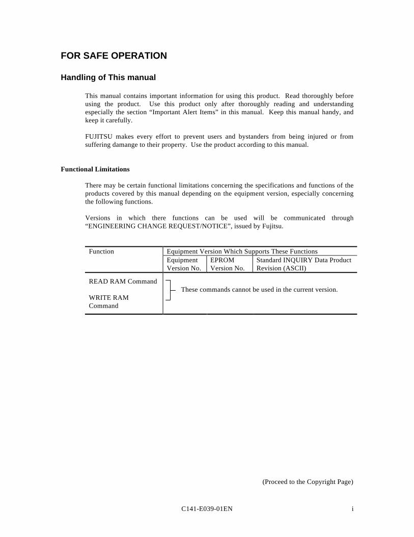
There may be certain functional limitations concerning the specifications and functions of theproducts covered by this manual depending on the equipment version, especially concerningthe following functions.
Versions in which there functions can be used will be communicated through“ENGINEERING CHANGE REQUEST/NOTICE”, issued by Fujitsu.
Function Equipment Version Which Supports These FunctionsEquipmentVersion No.
EPROMVersion No.
Standard INQUIRY Data ProductRevision (ASCII)
READ RAM Command These commands cannot be used in the current version.
WRITE RAMCommand
(Proceed to the Copyright Page)
C141-E039-01ENii
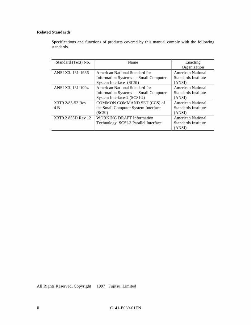
Related Standards
Specifications and functions of products covered by this manual comply with the followingstandards.
Standard (Text) No. Name EnactingOrganization
ANSI X3. 131-1986 American National Standard forInformation Systems --- Small ComputerSystem Interface (SCSI)
American NationalStandards Institute(ANSI)
ANSI X3. 131-1994 American National Standard forInformation Systems --- Small ComputerSystem Interface-2 (SCSI-2)
American NationalStandards Institute(ANSI)
X3T9.2/85-52 Rev4.B
COMMON COMMAND SET (CCS) ofthe Small Computer System Interface(SCSI)
American NationalStandards Institute(ANSI)
X3T9.2 855D Rev 12 WORKING DRAFT InformationTechnology SCSI-3 Parallel Interface
American NationalStandards Institute(ANSI)
All Rights Reserved, Copyright 1997 Fujitsu, Limited
C141-E039-01EN iii
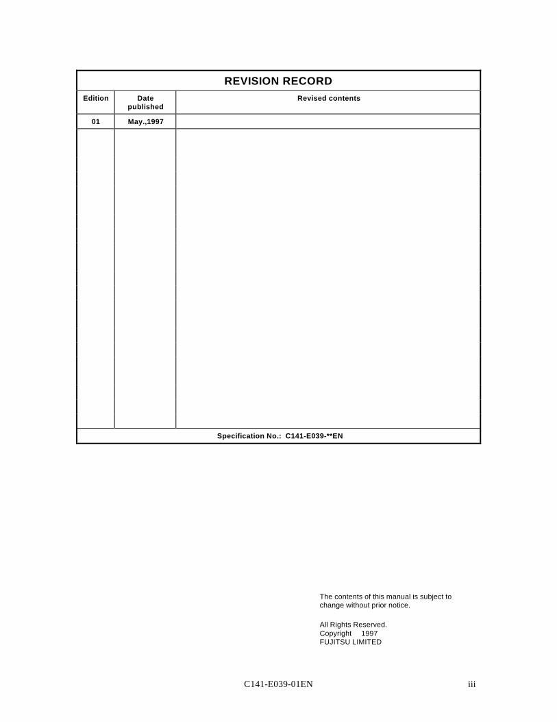
REVISION RECORDEdition Date
publishedRevised contents
01 May.,1997
Specification No.: C141-E039-**EN
The contents of this manual is subject tochange without prior notice.
All Rights Reserved.Copyright 1997FUJITSU LIMITED

C141-E039-01EN v
PREFACE
This manual explains concerning the MAA3182SC and MAB3091SC series 3.5 inch hard diskdrives with internal SCSI controller.
The purpose of this manual is to provide specifications of each command and detailedexplanations of their functions for use of these magnetic disk drives incorporated into usersystems, and to present the information necessary for creating host system software. Thismanual is written for users who have a basic knowledge of hard disk drives and their use incomputer systems.
The composition of manuals related to these disk drives and the range of subjects covered inthis manual are shown in “Manual Organization,” provided on a subsequent page. Please usethese other manuals along with this manual as necessary.
Composition and Contents of This Manual
This manual is composed of the 5 chapters shown below, a glossary and a list ofabbreviations.
Chapter 1 Command Processing
This chapter describes the basic logical specifications related to SCSI command processing inthe MAA3182SC and MAB3091SC series disk drives.
Chapter 2 Data Buffer Management
This chapter describes the data buffer configuration provided in the MAA3182SC andMAB3091SC series disk drives and concerning data transfer processing functions and cacheoperation.
Chapter 3 Command Specifications
This chapter describes detailed specifications of SCSI commands provided by theMAA3182SC and MAB3091SC series disk drives and how to use them..
Chapter 4 Sense Data and Error Recovery Methods
This chapter describes the configuration and contents of sense data which report to the hostsystem when an error occurs, etc., key information necessary for error recovery, recommendedprocedures for error recovery to be executed through host system software and retryprocessing executed internally in the MAA3182SC and MAB3091SC series disk drives forrecovery.
Chapter 5 Disk Media Management
This chapter describes the procedure for initializing the disk media, methods of treating mediadefects and data recovery methods for the MAA3182SC and MAB3091SC series disk drives.
vi C141-E039-01EN
Glossary
The glossary explains technical terms which are necessary to the reader’s understanding whenreading this manual.
List of Abbreviations
This list shows the full spelling of abbreviations used in this manual.
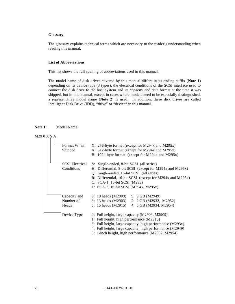
The model name of disk drives covered by this manual differs in its ending suffix (Note 1)depending on its device type (3 types), the electrical conditions of the SCSI interface used toconnect the disk drive to the host system and its capacity and data format at the time it wasshipped, but in this manual, except in cases where models need to be especially distinguished,a representative model name (Note 2) is used. In addition, these disk drives are calledIntelligent Disk Drive (IDD), “drive” or “device” in this manual.
Note 1: Model Name
M29 0 X S A
Format When X: 256-byte format (except for M294x and M295x)Shipped A: 512-byte format (except for M294x and M295x)
B: 1024-byte format (except for M294x and M295x)
SCSI Electrical S: Single-ended, 8-bit SCSI (all series)Conditions H: Differential, 8-bit SCSI (except for M294x and M295x)
Q: Single-ended, 16-bit SCSI (all series)R: Differential, 16-bit SCSI (except for M294x and M295x)C: SCA-1, 16-bit SCSI (M293)E: SCA-2, 16-bit SCSI (M294x, M295x)
Capacity and 9: 19 heads (M2909) 9: 9 GB (M2949)Number of 3: 13 heads (M2903) 2: 2 GB (M2932, M2952)Heads 5: 15 heads (M2915) 4: 5 GB (M2934, M2954)
Device Type 0: Full height, large capacity (M2903, M2909)1: Full height, high performance (M2915)3: Full height, large capacity, high performance (M293x)4: Full height, large capacity, high performance (M2949)5: 1-inch height, high performance (M2952, M2954)
C141-E039-01EN vii
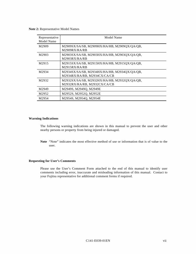
Note 2: Representative Model Names
RepresentativeModel Name
Model Name
M2909 M2909SX/SA/SB, M2909HX/HA/HB, M2909QX/QA/QB,M2909RX/RA/RB
M2903 M2903SX/SA/SB, M2903HX/HA/HB, M2903QX/QA/QB,M2903RX/RA/RB
M2915 M2915SX/SA/SB, M2915HX/HA/HB, M2915QX/QA/QB,M2915RX/RA/RB
M2934 M2934SX/SA/SB, M2934HX/HA/HB, M2934QX/QA/QB,M2934RX/RA/RB, M2934CX/CA/CB
M2932 M2932SX/SA/SB, M2932HX/HA/HB, M2932QX/QA/QB,M2932RX/RA/RB, M2932CX/CA/CB
M2949 M2949S, M2949Q, M2949EM2952 M2952S, M2952Q, M2952EM2954 M2954S, M2954Q, M2954E
Warning Indications
The following warning indications are shown in this manual to prevent the user and othernearby persons or property from being injured or damaged.
Note “Note” indicates the most effective method of use or information that is of value to theuser.
Requesting for User’s Comments
Please use the User’s Comment Form attached to the end of this manual to identify usercomments including error, inaccurate and misleading information of this manual. Contact toyour Fujitsu representative for additional comment forms if required.

C141-E039-01EN ix
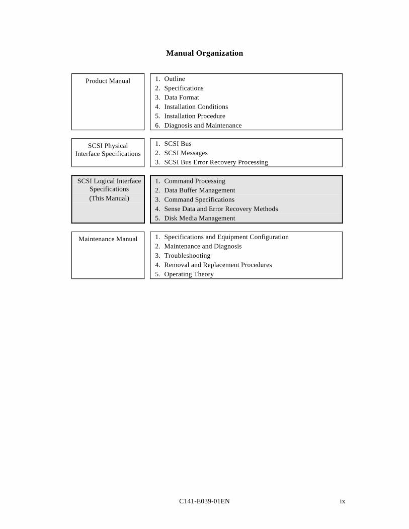
Manual Organization
Product Manual 1. Outline2. Specifications3. Data Format4. Installation Conditions5. Installation Procedure6. Diagnosis and Maintenance
SCSI PhysicalInterface Specifications
1. SCSI Bus2. SCSI Messages3. SCSI Bus Error Recovery Processing
SCSI Logical InterfaceSpecifications(This Manual)
1. Command Processing2. Data Buffer Management3. Command Specifications4. Sense Data and Error Recovery Methods5. Disk Media Management
Maintenance Manual 1. Specifications and Equipment Configuration2. Maintenance and Diagnosis3. Troubleshooting4. Removal and Replacement Procedures5. Operating Theory

C141-E039-01EN xi
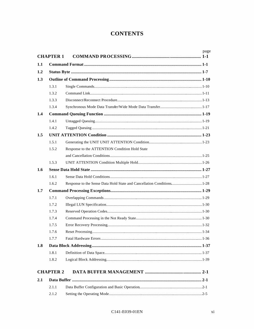
CONTENTS
pageCHAPTER 1 COMMAND PROCESSING................................ .......................... 1-1
1.1 Command Format ........................................................................................................... 1-1
1.2 Status Byte ....................................................................................................................... 1-7
1.3 Outline of Command Processing .................................................................................... 1-10
1.3.1 Single Commands............................................................................................................1-10
1.3.2 Command Link................................................................................................................1-11
1.3.3 Disconnect/Reconnect Procedure.....................................................................................1-13
1.3.4 Synchronous Mode Data Transfer/Wide Mode Data Transfer..........................................1-17
1.4 Command Queuing Function ......................................................................................... 1-19
1.4.1 Untagged Queuing...........................................................................................................1-19
1.4.2 Tagged Queuing ..............................................................................................................1-21
1.5 UNIT ATTENTION Condition ...................................................................................... 1-23
1.5.1 Generating the UNIT UNIT ATTENTION Condition.....................................................1-23
1.5.2 Response to the ATTENTION Condition Hold State
and Cancellation Conditions............................................................................................1-25
1.5.3 UNIT ATTENTION Condition Multiple Hold................................................................1-26
1.6 Sense Data Hold State ..................................................................................................... 1-27
1.6.1 Sense Data Hold Conditions............................................................................................1-27
1.6.2 Response to the Sense Data Hold State and Cancellation Conditions...............................1-28
1.7 Command Processing Exceptions................................................................................... 1-29
1.7.1 Overlapping Commands ..................................................................................................1-29
1.7.2 Illegal LUN Specification................................................................................................1-30
1.7.3 Reserved Operation Codes...............................................................................................1-30
1.7.4 Command Processing in the Not Ready State..................................................................1-30
1.7.5 Error Recovery Processing...............................................................................................1-32
1.7.6 Reset Processing..............................................................................................................1-34
1.7.7 Fatal Hardware Errors .....................................................................................................1-36
1.8 Data Block Addressing.................................................................................................... 1-37
1.8.1 Definition of Data Space..................................................................................................1-37
1.8.2 Logical Block Addressing................................................................................................1-39
CHAPTER 2 DATA BUFFER MANAGEMENT ................................ ............... 2-1
2.1 Data Buffer ...................................................................................................................... 2-1
2.1.1 Data Buffer Configuration and Basic Operation...............................................................2-1
2.1.2 Setting the Operating Mode.............................................................................................2-5
C141-E039-01ENxii
2.2 Look-ahead Cache Mechanism ...................................................................................... 2-7
2.2.1 Caching Operation...........................................................................................................2-7
2.2.2 Caching Parameters.........................................................................................................2-9
2.2.3 Look-ahead Operation, Look-ahead Volume....................................................................2-10
2.3 Write Cache ..................................................................................................................... 2-11
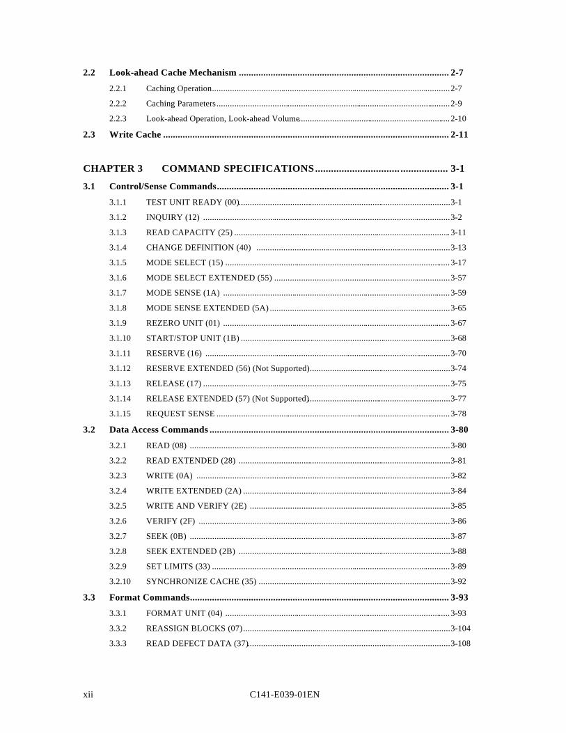
CHAPTER 3 COMMAND SPECIFICATIONS................................ .................. 3-1
3.1 Control/Sense Commands............................................................................................... 3-1
3.1.1 TEST UNIT READY (00)...............................................................................................3-1
3.1.2 INQUIRY (12) ...............................................................................................................3-2
3.1.3 READ CAPACITY (25) .................................................................................................3-11
3.1.4 CHANGE DEFINITION (40) .......................................................................................3-13
3.1.5 MODE SELECT (15) .....................................................................................................3-17
3.1.6 MODE SELECT EXTENDED (55) ...............................................................................3-57
3.1.7 MODE SENSE (1A) ......................................................................................................3-59
3.1.8 MODE SENSE EXTENDED (5A) .................................................................................3-65
3.1.9 REZERO UNIT (01) ......................................................................................................3-67
3.1.10 START/STOP UNIT (1B) ..............................................................................................3-68
3.1.11 RESERVE (16) ..............................................................................................................3-70
3.1.12 RESERVE EXTENDED (56) (Not Supported)...............................................................3-74
3.1.13 RELEASE (17) ...............................................................................................................3-75
3.1.14 RELEASE EXTENDED (57) (Not Supported)................................................................3-77
3.1.15 REQUEST SENSE .........................................................................................................3-78
3.2 Data Access Commands .................................................................................................. 3-80
3.2.1 READ (08) .....................................................................................................................3-80
3.2.2 READ EXTENDED (28) ...............................................................................................3-81
3.2.3 WRITE (0A) ..................................................................................................................3-82
3.2.4 WRITE EXTENDED (2A) .............................................................................................3-84
3.2.5 WRITE AND VERIFY (2E) ..........................................................................................3-85
3.2.6 VERIFY (2F) .................................................................................................................3-86
3.2.7 SEEK (0B) .....................................................................................................................3-87
3.2.8 SEEK EXTENDED (2B) ...............................................................................................3-88
3.2.9 SET LIMITS (33) ...........................................................................................................3-89
3.2.10 SYNCHRONIZE CACHE (35) ......................................................................................3-92
3.3 Format Commands.......................................................................................................... 3-93
3.3.1 FORMAT UNIT (04) .....................................................................................................3-93
3.3.2 REASSIGN BLOCKS (07).............................................................................................3-104
3.3.3 READ DEFECT DATA (37)...........................................................................................3-108
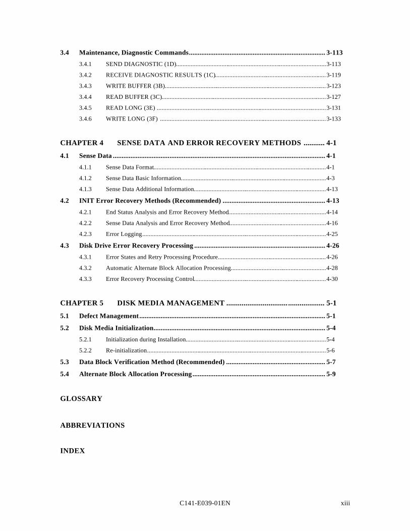
C141-E039-01EN xiii
3.4 Maintenance, Diagnostic Commands............................................................................. 3-113
3.4.1 SEND DIAGNOSTIC (1D).............................................................................................3-113
3.4.2 RECEIVE DIAGNOSTIC RESULTS (1C).....................................................................3-119
3.4.3 WRITE BUFFER (3B)....................................................................................................3-123
3.4.4 READ BUFFER (3C)......................................................................................................3-127
3.4.5 READ LONG (3E) .........................................................................................................3-131
3.4.6 WRITE LONG (3F) .......................................................................................................3-133
CHAPTER 4 SENSE DATA AND ERROR RECOVERY METHODS ........... 4-1
4.1 Sense Data ........................................................................................................................ 4-1
4.1.1 Sense Data Format...........................................................................................................4-1
4.1.2 Sense Data Basic Information..........................................................................................4-3
4.1.3 Sense Data Additional Information..................................................................................4-13
4.2 INIT Error Recovery Methods (Recommended) .......................................................... 4-13
4.2.1 End Status Analysis and Error Recovery Method.............................................................4-14
4.2.2 Sense Data Analysis and Error Recovery Method............................................................4-16
4.2.3 Error Logging..................................................................................................................4-25
4.3 Disk Drive Error Recovery Processing .......................................................................... 4-26
4.3.1 Error States and Retry Processing Procedure...................................................................4-26
4.3.2 Automatic Alternate Block Allocation Processing...........................................................4-28
4.3.3 Error Recovery Processing Control..................................................................................4-30
CHAPTER 5 DISK MEDIA MANAGEMENT ................................ ................... 5-1
5.1 Defect Management......................................................................................................... 5-1
5.2 Disk Media Initialization................................................................................................. 5-4
5.2.1 Initialization during Installation.......................................................................................5-4
5.2.2 Re-initialization...............................................................................................................5-6
5.3 Data Block Verification Method (Recommended) ........................................................ 5-7
5.4 Alternate Block Allocation Processing........................................................................... 5-9
GLOSSARY
ABBREVIATIONS
INDEX
C141-E039-01ENxiv
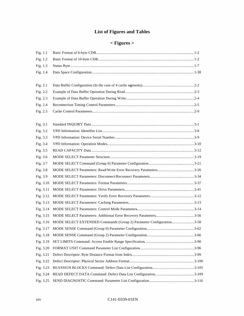
List of Figures and Tables
< Figures >
Fig. 1.1 Basic Format of 6-byte CDB......................................................................................................1-2
Fig. 1.2 Basic Format of 10-byte CDB....................................................................................................1-2
Fig. 1.3 Status Byte.................................................................................................................................1-7
Fig. 1.4 Data Space Configuration...........................................................................................................1-38
Fig. 2.1 Data Buffer Configuration (In the case of 4 cache segments)......................................................2-2
Fig. 2.2 Example of Data Buffer Operation During Read........................................................................2-3
Fig. 2.3 Example of Data Buffer Operation During Write.......................................................................2-4
Fig. 2.4 Reconnection Timing Control Parameters..................................................................................2-5
Fig. 2.5 Cache Control Parameters..........................................................................................................2-9
Fig. 3.1 Standard INQUIRY Data ...........................................................................................................3-1
Fig. 3.2 VPD Information: Identifier List................................................................................................3-8
Fig. 3.3 VPD Information: Device Serial Number...................................................................................3-9
Fig. 3.4 VPD Information: Operation Modes...........................................................................................3-10
Fig. 3.5 READ CAPACITY Data ...........................................................................................................3-12
Fig. 3.6 MODE SELECT Parameter Structure........................................................................................3-19
Fig. 3.7 MODE SELECT Command (Group 0) Parameter Configuration...............................................3-21
Fig. 3.8 MODE SELECT Parameters: Read/Write Error Recovery Parameters.......................................3-26
Fig. 3.9 MODE SELECT Parameters: Disconnect/Reconnect Parameters...............................................3-34
Fig. 3.10 MODE SELECT Parameters: Format Parameters......................................................................3-37
Fig. 3.11 MODE SELECT Parameters: Drive Parameters.........................................................................3-41
Fig. 3.12 MODE SELECT Parameters: Verify Error Recovery Parameters..............................................3-12
Fig. 3.13 MODE SELECT Parameters: Caching Parameters.....................................................................3-13
Fig. 3.14 MODE SELECT Parameters: Control Mode Parameters............................................................3-14
Fig. 3.15 MODE SELECT Parameters: Additional Error Recovery Parameters........................................3-56
Fig. 3.16 MODE SELECT EXTENDED Commands (Group 2) Parameter Configuration........................3-58
Fig. 3.17 MODE SENSE Command (Group 0) Parameter Configuration..................................................3-62
Fig. 3.18 MODE SENSE Command (Group 2) Parameter Configuration..................................................3-66
Fig. 3.19 SET LIMITS Command: Access Enable Range Specification....................................................3-90
Fig. 3.20 FORMAT UNIT Command Parameter List Configuration.........................................................3-96
Fig. 3.21 Defect Descriptor: Byte Distance Format from Index.................................................................3-99
Fig. 3.22 Defect Descriptor: Physical Sector Address Format...................................................................3-100
Fig. 3.23 REASSIGN BLOCKS Command: Defect Data List Configuration............................................3-105
Fig. 3.24 READ DEFECT DATA Command: Defect Data List Configuration.........................................3-109
Fig. 3.25 SEND DIAGNOSTIC Command: Parameter List Configuration...............................................3-116
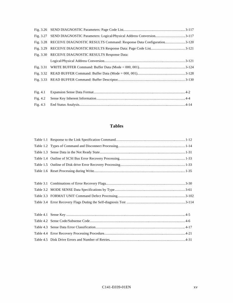
C141-E039-01EN xv
Fig. 3.26 SEND DIAGNOSTIC Parameters: Page Code List....................................................................3-117
Fig. 3.27 SEND DIAGNOSTIC Parameters: Logical/Physical Address Conversion.................................3-117
Fig. 3.28 RECEIVE DIAGNOSTIC RESULTS Command: Response Data Configuration.......................3-120
Fig. 3.29 RECEIVE DIAGNOSTIC RESULTS Response Data: Page Code List......................................3-121
Fig. 3.30 RECEIVE DIAGNOSTIC RESULTS Response Data:
Logical/Physical Address Conversion.........................................................................................3-121
Fig. 3.31 WRITE BUFFER Command: Buffer Data (Mode = 000, 001)...................................................3-124
Fig. 3.32 READ BUFFER Command: Buffer Data (Mode = 000, 001).....................................................3-128
Fig. 3.33 READ BUFFER Command: Buffer Descriptor..........................................................................3-130
Fig. 4.1 Expansion Sense Data Format....................................................................................................4-2
Fig. 4.2 Sense Key Inherent Information.................................................................................................4-4
Fig. 4.3 End Status Analysis....................................................................................................................4-14
Tables
Table 1.1 Response to the Link Specification Command............................................................................1-12
Table 1.2 Types of Command and Disconnect Processing..........................................................................1-14
Table 1.3 Sense Data in the Not Ready State.............................................................................................1-31
Table 1.4 Outline of SCSI Bus Error Recovery Processing........................................................................1-33
Table 1.5 Outline of Disk drive Error Recovery Processing.......................................................................1-33
Table 1.6 Reset Processing during Write....................................................................................................1-35
Table 3.1 Combinations of Error Recovery Flags.......................................................................................3-30
Table 3.2 MODE SENSE Data Specifications by Type.............................................................................3-61
Table 3.3 FORMAT UNIT Command Defect Processing..........................................................................3-102
Table 3.4 Error Recovery Flags During the Self-diagnosis Test ................................................................3-114
Table 4.1 Sense Key ..................................................................................................................................4-5
Table 4.2 Sense Code/Subsense Code........................................................................................................4-6
Table 4.3 Sense Data Error Classification..................................................................................................4-17
Table 4.4 Error Recovery Processing Procedure.........................................................................................4-21
Table 4.5 Disk Drive Errors and Number of Retries...................................................................................4-31

C141-E039-01EN 1 - 1
CHAPTER 1 COMMAND PROCESSING
1.1 Command Format
1.2 Status Byte
1.3 Outline of Command Processing
1.4 Command Queuing Function
1.5 UNIT ATTENTION Conditions
1.6 Sense Data Maintenance State
1.7 Command Processing Exceptions
1.8 Data Block Addressing
This chapter describes the basic logical specifications of the IDD command processing functions.
Note The IDD operates as the target (TARG) on the SCSI bus. In the explanations in thischapter, the IDD is mentioned as “TARG”, except in cases where a particularly cleardistinction is necessary.
1.1 Command Format
Input/output operation commands from INIT (initiator) to the IDD are accomplished by theCDB (Command Descriptor Block). The CDB is information transferred from INIT to TARGin the COMMAND phase. In a number of commands, the parameters which are necessary forcommand execution in the DATA OUT phase may be specified in addition to the CDBspecification. Details concerning these are described in the specifications for each individualcommand in Chapter 3.
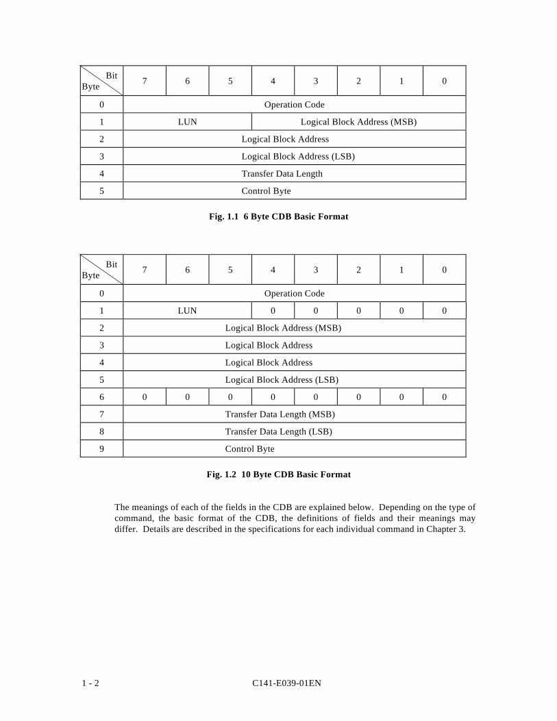
The CDB used by the IDD has 2 formats, one with a length of 6 bytes and the other with alength of 10 bytes. The basic format of each respective CDB is shown in Fig. 1.1 and Fig. 1.2.
C141-E039-01EN1 - 2
BitByte 7 6 5 4 3 2 1 0
0 Operation Code
1 LUN Logical Block Address (MSB)
2 Logical Block Address
3 Logical Block Address (LSB)
4 Transfer Data Length
5 Control Byte
Fig. 1.1 6 Byte CDB Basic Format
BitByte 7 6 5 4 3 2 1 0
0 Operation Code
1 LUN 0 0 0 0 0
2 Logical Block Address (MSB)
3 Logical Block Address
4 Logical Block Address
5 Logical Block Address (LSB)
6 0 0 0 0 0 0 0 0
7 Transfer Data Length (MSB)
8 Transfer Data Length (LSB)
9 Control Byte
Fig. 1.2 10 Byte CDB Basic Format
The meanings of each of the fields in the CDB are explained below. Depending on the type ofcommand, the basic format of the CDB, the definitions of fields and their meanings maydiffer. Details are described in the specifications for each individual command in Chapter 3.
C141-E039-01EN 1 - 3
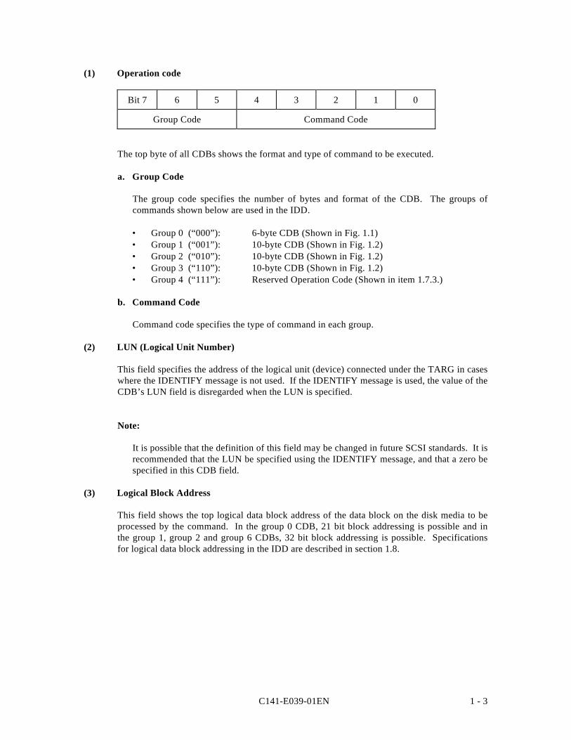
(1) Operation code
Bit 7 6 5 4 3 2 1 0
Group Code Command Code
The top byte of all CDBs shows the format and type of command to be executed.
a. Group Code
The group code specifies the number of bytes and format of the CDB. The groups ofcommands shown below are used in the IDD.
• Group 0 (“000”): 6-byte CDB (Shown in Fig. 1.1)• Group 1 (“001”): 10-byte CDB (Shown in Fig. 1.2)• Group 2 (“010”): 10-byte CDB (Shown in Fig. 1.2)• Group 3 (“110”): 10-byte CDB (Shown in Fig. 1.2)• Group 4 (“111”): Reserved Operation Code (Shown in item 1.7.3.)
b. Command Code
Command code specifies the type of command in each group.
(2) LUN (Logical Unit Number)
This field specifies the address of the logical unit (device) connected under the TARG in caseswhere the IDENTIFY message is not used. If the IDENTIFY message is used, the value of theCDB’s LUN field is disregarded when the LUN is specified.
Note:
It is possible that the definition of this field may be changed in future SCSI standards. It isrecommended that the LUN be specified using the IDENTIFY message, and that a zero bespecified in this CDB field.
(3) Logical Block Address
This field shows the top logical data block address of the data block on the disk media to beprocessed by the command. In the group 0 CDB, 21 bit block addressing is possible and inthe group 1, group 2 and group 6 CDBs, 32 bit block addressing is possible. Specificationsfor logical data block addressing in the IDD are described in section 1.8.
C141-E039-01EN1 - 4
(4) Transfer Data Length
In this field, the length of data to be transferred between INIT and TARG when the commandis executed is specified by the number of logical data blocks or the number of bytes. Insubsequent descriptions, the former is called the “transfer block count” and the latter is calledthe “transfer byte length” or “parameter list length.”
Furthermore, this field may be used with a different meaning, or it may not have any meaningat all, depending on the type of command. There are also some commands which allocate 3 ormore bytes as the transfer data length field. Detailed specifications of these commands aredescribed in the individual command specifications in Chapter 3.
a. Transfer Block Count
When the “Transfer Data Length” is specified as the “Transfer Block Count,” this fieldspecifies the number of logical data blocks to be transferred between INIT and the IDD.
In commands where this field is 1 byte in length, if the field’s specified value is 0, it isregarded as specifying 256 blocks, and it is possible to specify a block count ranging from1 to 256 blocks. On the other hand, in commands where this field is 2 bytes in length, ifthe field’s specified value is 0, no data transfer is executed. It is possible to specify ablock count ranging from 0 to 65,535 blocks.
b. Transfer Byte Length or Parameter List Length
When this field is specified as the “Transfer Byte Length” or “Parameter List Length,” thatcommand specifies data length to be transferred between the INIT and the IDD, expressedas the number of bytes. When 0 is specified in this field, data transfer is not executed,except in cases where it is expressly stated in the individual command specifications inChapter 3.
In commands which send parameters necessary for executing a command from the INIT tothe IDD, this field is called the “Parameter List Length,” and it specifies the total numberof types in the parameter list which the INIT is sending.
On the other hand, in commands for receiving information from the IDD (REQUESTSENSE, INQUIRY, etc.), this field is called the “Transfer Byte Length,” and specifies themaximum number of bytes (the which the INIT can receive (the number of bytes of areasecured within the INIT for receiving information). The IDD transfers either the numberof effective bytes of the type of information specified in the command, or the valuespecified in the “Transfer Byte Length” field, whichever is the smallest number of bytes,and only that number, to the INIT.
C141-E039-01EN 1 - 5
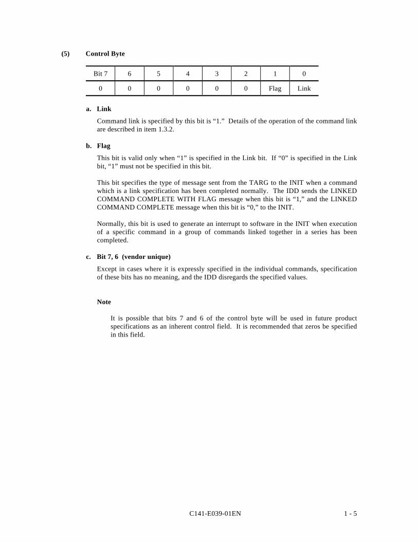
(5) Control Byte
Bit 7 6 5 4 3 2 1 0
0 0 0 0 0 0 Flag Link
a. Link
Command link is specified by this bit is “1.” Details of the operation of the command linkare described in item 1.3.2.
b. Flag
This bit is valid only when “1” is specified in the Link bit. If “0” is specified in the Linkbit, “1” must not be specified in this bit.
This bit specifies the type of message sent from the TARG to the INIT when a commandwhich is a link specification has been completed normally. The IDD sends the LINKEDCOMMAND COMPLETE WITH FLAG message when this bit is “1,” and the LINKEDCOMMAND COMPLETE message when this bit is “0,” to the INIT.
Normally, this bit is used to generate an interrupt to software in the INIT when executionof a specific command in a group of commands linked together in a series has beencompleted.
c. Bit 7, 6 (vendor unique)
Except in cases where it is expressly specified in the individual commands, specificationof these bits has no meaning, and the IDD disregards the specified values.
Note
It is possible that bits 7 and 6 of the control byte will be used in future productspecifications as an inherent control field. It is recommended that zeros be specifiedin this field.
C141-E039-01EN1 - 6
(6) Handling an Illegal CDB
If there is an error in the contents of a description (specification) in the CDB, or if there is anerror in the specifications in parameters transferred from the INIT, that command ends with aCHECK CONDITION status. In the case of a command to change the data on the disk media,when there is an error in the CDB’s specifications, the disk media is not changed by thatcommand, but when there is an error in the parameters transferred in the DATA OUT phase,the contents of the disk media in the range specified by the command may be changed. Also,even in cases where there is an error in the CDB’s specifications in a command accompanyingthe DATA OUT phase, the DATA OUT phase is executed after the COMMAND phase isterminated, but those data are not used. For example, if there is an error in the CDBspecification of a WRITE command, the IDD executes the transfers several bytes of data (thedata length to be transferred is not specified), but those data are not written to the disk media.Details are described in the individual command specifications in Chapter 3.
If there is an error in the CDB specification in a command which executes disconnectprocessing (shown in item 1.3.3), the disconnect processing may be executed after theCOMMAND phase is terminated. In this case, reconnect processing is executed afterward andthe status (CHECK CONDITION) is reported.
Note:
If a CDB with an undefined group code (group 3, 4, 5) is specified, the IDD requeststransfer of 10 bytes in the COMMAND phase and if the group code [group 5] is specified,it requests transfer of 12 bytes. After that has been received, the status (CHECKCONDITION) is reported.
C141-E039-01EN 1 - 7
1.2 Status Byte
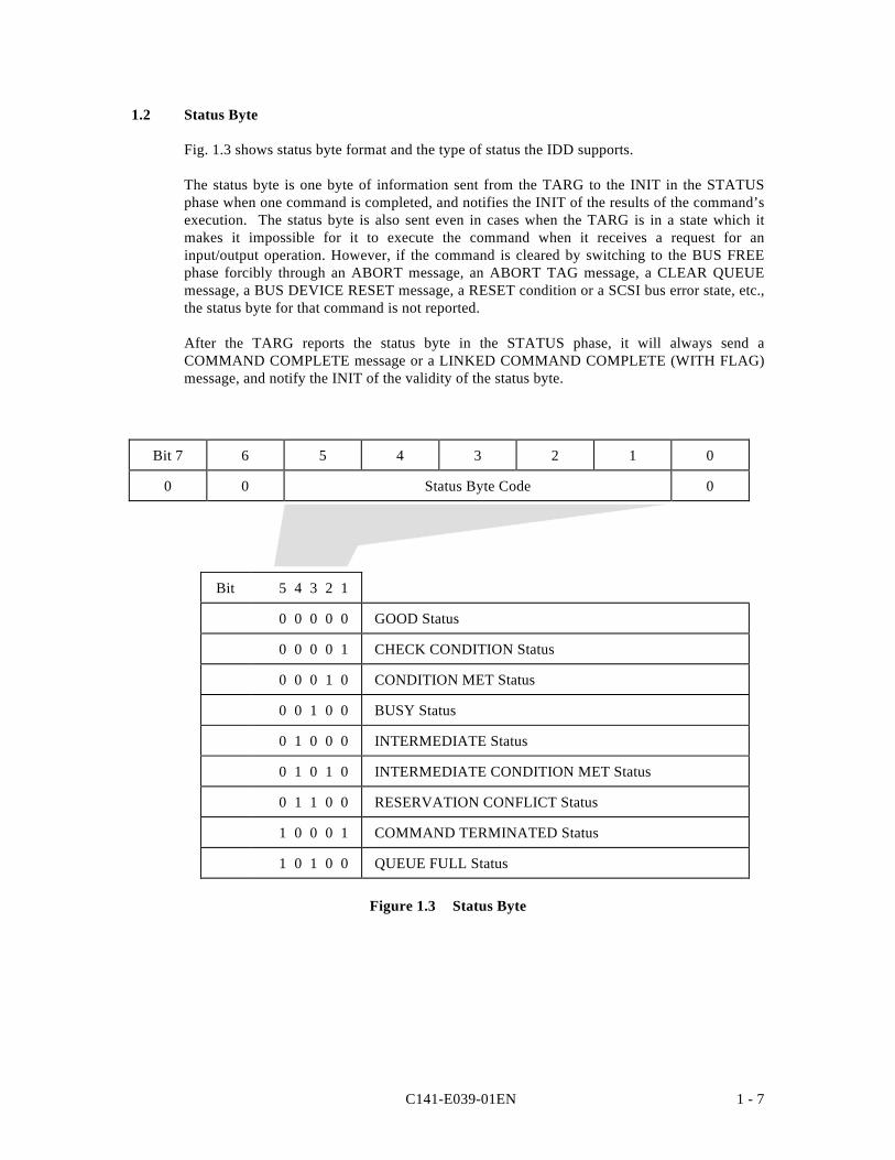
Fig. 1.3 shows status byte format and the type of status the IDD supports.
The status byte is one byte of information sent from the TARG to the INIT in the STATUSphase when one command is completed, and notifies the INIT of the results of the command’sexecution. The status byte is also sent even in cases when the TARG is in a state which itmakes it impossible for it to execute the command when it receives a request for aninput/output operation. However, if the command is cleared by switching to the BUS FREEphase forcibly through an ABORT message, an ABORT TAG message, a CLEAR QUEUEmessage, a BUS DEVICE RESET message, a RESET condition or a SCSI bus error state, etc.,the status byte for that command is not reported.
After the TARG reports the status byte in the STATUS phase, it will always send aCOMMAND COMPLETE message or a LINKED COMMAND COMPLETE (WITH FLAG)message, and notify the INIT of the validity of the status byte.
Bit 7 6 5 4 3 2 1 0
0 0 Status Byte Code 0
Bit 5 4 3 2 1
0 0 0 0 0 GOOD Status
0 0 0 0 1 CHECK CONDITION Status
0 0 0 1 0 CONDITION MET Status
0 0 1 0 0 BUSY Status
0 1 0 0 0 INTERMEDIATE Status
0 1 0 1 0 INTERMEDIATE CONDITION MET Status
0 1 1 0 0 RESERVATION CONFLICT Status
1 0 0 0 1 COMMAND TERMINATED Status
1 0 1 0 0 QUEUE FULL Status
Figure 1.3 Status Byte
C141-E039-01EN1 - 8
(1) GOOD Status
This status indicates that execution of the command ended normally.
(2) CHECK CONDITION Status
This status is reported in the following cases a) to c). The IDD generates sense data when itreports this status and displays the detailed cause. The INIT issues a REQUEST SENSEcommand when it receives this status and should sample sense data.
a) If the sense key of the sense data indicates RECOVERED ERROR [=1], the last command,which is the final command, indicates that it ended normally with the error recoveryprocessing executed by the IDD.
b) If the sense key of the sense data indicates UNIT ATTENTION [=6], it indicates that theIDD was holding the UNIT ATTENTION condition. Details of the UNIT ATTENTIONcondition are described in section 1.5.
c) In cases other than the above, it indicates that command execution is impossible, or thatcommand execution was terminated abnormally.
(3) CONDITION MET Status
This status indicates that the PRE-FETCH command condition has been met, and is reportedwhen it is possible to secure the cache memory area necessary for reading all the logical datablocks specified in the PRE-FETCH command (in the case of “Immed = 1”), or when readingof all the specified logical data blocks is completed (in the case of “Immed = 0”).
The IDD does not support the PRE-FETCH command. Therefore, reporting of this status isnot reported.
(4) BUSY Status
This status indicates that the IDD is in the busy state or that it cannot receive a new command.Normally, an INIT that receives this status reissues the original command after waiting anappropriate period of time.
The IDD reports the BUSY status in the following cases (the command stack function isexplained in section 1.4).
a) If the IDD receives a new command while it is executing a command, is queuing or isexecuting its initial self-diagnosis (except a command with an object other than disconnectprocessing as shown in item 1.3.3), if the INIT which issued that command does notsatisfy the disconnect enable conditions.
b) If the IDD receives a command with an object other than disconnect processing (as shownin item 1.3.3) while it is executing a command, is queuing or is executing its initial self-diagnosis.
c) If the DISCONNECT message for command queuing has been rejected by the INIT.
d) If a command with untagged disconnect processing as its object is received while thecommand queue is full.
C141-E039-01EN 1 - 9
(5) INTERMEDIATE Status
This status indicates that a command which specifies a link (except the final command in agroup of linked commands with “1” as its Link bit) has been completed normally. If acommand which specifies a link is completed abnormally and the CHECK CONDITIONstatus or RESERVATION CONFLICT status is reported, the command link is broken an thesubsequent linked commands are not executed.
(6) INTERMEDIATE CONDITION MET Status
This status indicates that the PRE-FETCH command intermediate condition has been met, andis reported when it is possible to secure the cache memory area necessary to read all the logicaldata blocks specified in a PRE-FETCH command which specifies a link (in the case of“Immed = 1”), or when reading of all the specified logical data blocks is completed (in thecase of “Immed = 0”).
The IDD does not support the PRE-FETCH command. Therefore, this status is not reported.
(7) RESERVATION CONFLICT Status
This status indicates that the IDD is reserved by another INIT, and that use is impossible untilthe reserved status is canceled. Normally, an INIT which receives this status reissues theoriginal command after waiting an appropriate period of time.
(8) COMMAND TERMINATED Status
This status is reported when the IDD has completed the input/output operation it wasexecuting when it received a TERMINATE I/O PROCESS message from the INIT.
(9) QUEUE FULL Status
This status is reported if the IDD cannot register a tagged command it has received in thecommand queue because there is no empty space in the command queue.
C141-E039-01EN1 - 10
1.3 Outline of Command Processing
1.3.1 Single Commands
Some processing examples of single commands which are the most basic operations on theSCSI bus are shown below. Furthermore, if disconnect processing is permitted, it may beaccompanied by disconnect/reconnect processing during the interval until execution iscompleted, depending on the type of command, but this operation is omitted in the followingexplanation. The disconnect function is described in item 1.3.3.
1) The INIT sets the command’s initial values in the command pointer, data pointer andstatus pointer.
2) The INIT selects the TARG in the SELECTION phase after acquiring the right to use theSCSI bus in the ARBITRATION phase. After the SELECTION phase is ended, the rightto control the SCSI bus is entrusted to the TARG.
3) If the ATTENTION condition exists when the TARG responds to the SELECTION phase,the TARG executes the MESSAGE OUT phase. Normally, the INIT sends the IDENTIFYmessage as the initial message and specifies the device (LUN) that is the object of theoperation.
4) The TARG next executes the COMMAND phase and receives the CDB from the INIT.The TARG judges the length of the CDB by the group code in the first byte of the CDBand requests transfer of the necessary number of bytes.
5) The TARG interprets the contents of the command and executes the requested operation.In the case of commands for which data transfer on the SCSI bus is necessary, the DATAIN or the DATA OUT phase is executed.
6) When execution of the command is completed, the TARG notifies the INIT of theexecution results by the status byte in the STATUS phase.
7) The TARG notifies the INIT of the COMMAND COMPLETE message in the finalMESSAGE IN phase and enters the BUS FREE phase.
C141-E039-01EN 1 - 11
1.3.2 Command Link
The command link function is a function which causes the TARG to execute continuousprocessing of multiple commands. Some examples of command link processing are shownbelow.
1) The INIT sets the command’s initial values in the command pointer, data pointer andstatus pointer.
2) Acquiring of the right to use the SCSI bus, selection of the TARG and specification of theLUN by the IDENTIFY message are the same as in the case of single commands.
3) The TARG receives commands from the INIT in the COMMAND phase, but “1” isspecified in the Link bit of the CDB’s control byte.
4) The TARG analyzes the command and executes the requested processing.
5) If processing of the command is completed normally, the TARG notifies the INIT of theINTERMEDIATE status in the STATUS phase. At this time, the command link functionbecomes effective.
6) The TARG informs the INIT of the LINKED COMMAND COMPLETE or the LINKEDCOMMAND COMPLETE WITH FLAG message, depending on the value of the Flag bitin the CDB’s control byte. When the INIT has received the LINKED COMMANDCOMPLETE (WITH FLAG) message, the command, data and status pointers are updatedto the initial values for the next command in the link.
7) The TARG enters the COMMAND phase immediately after the MESSAGE IN phase andreceives the command it is to execute next. After that, it performs either single command(Link bit = “0”) processing or command link (Link bit = “1”) processing.
The command link continues until a command with “0” specified in the Link bit of its CDB isissued or until a command terminates abnormally.
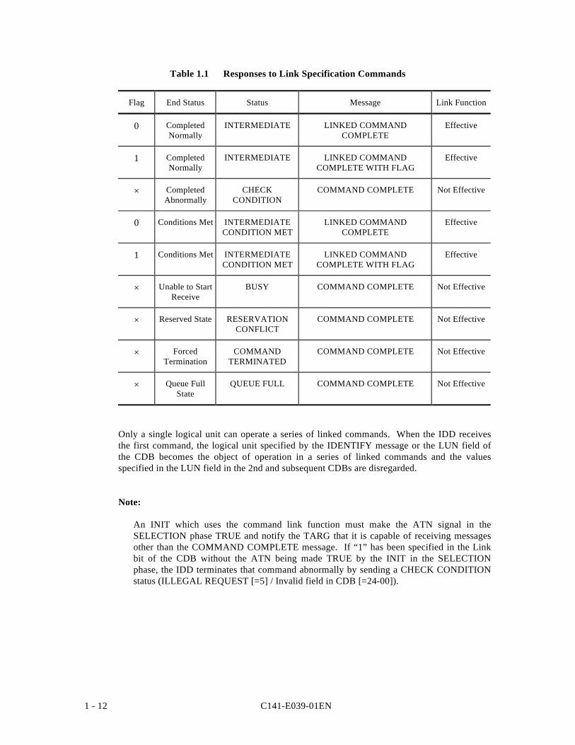
The command link function is made effective only in the case that commands with linkspecifications are completed normally. If a command with a link specification is completed inan error state or in an exception state, the command link function is invalidated. Table 1.1shows the response of the IDD when commands with a Link specification are terminated.
C141-E039-01EN1 - 12
Table 1.1 Responses to Link Specification Commands
Flag End Status Status Message Link Function
0 CompletedNormally
INTERMEDIATE LINKED COMMANDCOMPLETE
Effective
1 CompletedNormally
INTERMEDIATE LINKED COMMANDCOMPLETE WITH FLAG
Effective
× CompletedAbnormally
CHECKCONDITION
COMMAND COMPLETE Not Effective
0 Conditions Met INTERMEDIATECONDITION MET
LINKED COMMANDCOMPLETE
Effective
1 Conditions Met INTERMEDIATECONDITION MET
LINKED COMMANDCOMPLETE WITH FLAG
Effective
× Unable to StartReceive
BUSY COMMAND COMPLETE Not Effective
× Reserved State RESERVATIONCONFLICT
COMMAND COMPLETE Not Effective
× ForcedTermination
COMMANDTERMINATED
COMMAND COMPLETE Not Effective
× Queue FullState
QUEUE FULL COMMAND COMPLETE Not Effective
Only a single logical unit can operate a series of linked commands. When the IDD receivesthe first command, the logical unit specified by the IDENTIFY message or the LUN field ofthe CDB becomes the object of operation in a series of linked commands and the valuesspecified in the LUN field in the 2nd and subsequent CDBs are disregarded.
Note:
An INIT which uses the command link function must make the ATN signal in theSELECTION phase TRUE and notify the TARG that it is capable of receiving messagesother than the COMMAND COMPLETE message. If “1” has been specified in the Linkbit of the CDB without the ATN being made TRUE by the INIT in the SELECTIONphase, the IDD terminates that command abnormally by sending a CHECK CONDITIONstatus (ILLEGAL REQUEST [=5] / Invalid field in CDB [=24-00]).
C141-E039-01EN 1 - 13
1.3.3 Disconnect/Reconnect Processing
When processing is performed by the TARG during the command execution process whichdoes not require operation on the SCSI bus, the TARG temporarily returns the SCSI bus to theBUS FREE phase by disconnect processing, making it possible for the TARG to execute thecommand internally. Through this function, the INIT is enabled to process multiplecommands on the SCSI bus.
(1) Conditions where disconnects are permitted and commands which are the object ofdisconnect processing
If all of the conditions shown below for permitting a disconnect are satisfied, the IDD executesdisconnect processing. However, As shown in Table 1.2, disconnect processing may be validor invalid, and the disconnect processing execution timing may differ, depending on the typeof command.
Conditions for Permitting a Disconnect
1) The SCSI ID of the INIT is notified in the SELECTION phase.
2) The INIT generates the ATTENTION condition in the selection phase.
3) The INIT notifies the TARG that disconnect processing is permitted by an IDENTIFYmessage.
C141-E039-01EN1 - 14
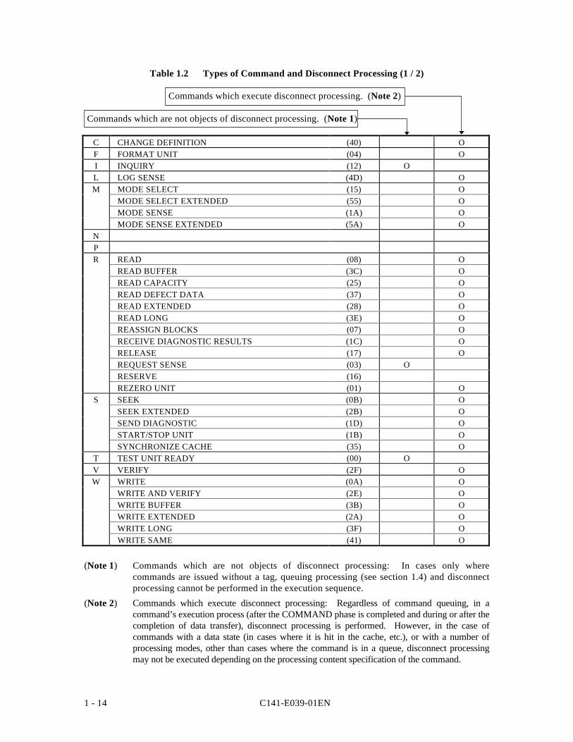
Table 1.2 Types of Command and Disconnect Processing (1 / 2)
Commands which execute disconnect processing. (Note 2)
Commands which are not objects of disconnect processing. (Note 1)
C CHANGE DEFINITION (40) OF FORMAT UNIT (04) OI INQUIRY (12) OL LOG SENSE (4D) OM MODE SELECT (15) O
MODE SELECT EXTENDED (55) OMODE SENSE (1A) OMODE SENSE EXTENDED (5A) O
NPR READ (08) O
READ BUFFER (3C) OREAD CAPACITY (25) OREAD DEFECT DATA (37) OREAD EXTENDED (28) OREAD LONG (3E) OREASSIGN BLOCKS (07) ORECEIVE DIAGNOSTIC RESULTS (1C) ORELEASE (17) OREQUEST SENSE (03) ORESERVE (16)REZERO UNIT (01) O
S SEEK (0B) OSEEK EXTENDED (2B) OSEND DIAGNOSTIC (1D) OSTART/STOP UNIT (1B) OSYNCHRONIZE CACHE (35) O
T TEST UNIT READY (00) OV VERIFY (2F) OW WRITE (0A) O
WRITE AND VERIFY (2E) OWRITE BUFFER (3B) OWRITE EXTENDED (2A) OWRITE LONG (3F) OWRITE SAME (41) O
(Note 1) Commands which are not objects of disconnect processing: In cases only wherecommands are issued without a tag, queuing processing (see section 1.4) and disconnectprocessing cannot be performed in the execution sequence.
(Note 2) Commands which execute disconnect processing: Regardless of command queuing, in acommand’s execution process (after the COMMAND phase is completed and during or after thecompletion of data transfer), disconnect processing is performed. However, in the case ofcommands with a data state (in cases where it is hit in the cache, etc.), or with a number ofprocessing modes, other than cases where the command is in a queue, disconnect processingmay not be executed depending on the processing content specification of the command.
C141-E039-01EN 1 - 15
(2) Basic Disconnect Processing Procedure
Disconnect processing is executed basically by the following processing procedure.
1) If the IDD judges that it is possible for it to disconnect from the SCSI bus during executionof a command, it sends a DISCONNECT message to the INIT and enters the BUS FREEphase. At this time, if necessary, the IDD sends a message to activate a pointer in the INITwhich precedes sending of the DISCONNECT message. Furthermore, for detailsconcerning the pointer mechanism, refer to the SCSI pointer description in “SCSI PhysicalInterface Specifications” and “Chapter 2 SCSI Messages.”
2) After the IDD enters the BUS FREE phase, it is possible for the INIT to issue othercommands. Also, it is possible for an IDD which has performed disconnect processing toreceive input/output operation requests from each INIT (this is explained in the descriptionof the command queuing function in section 1.4).
3) The IDD executes the command which performs disconnect processing internally.
4) After that, the IDD executes reconnection processing at the point when it is necessary foroperation on the SCSI bus, reconnecting with the INIT (See item (6) concerningreconnection processing).
(3) Disconnect Processing Procedure after COMMAND Phase Execution
If commands are queued (see section 1.4), disconnect processing is performed immediately after theCOMMAND phase execution is completed. In this case, the IDD switches from the COMMANDphase to the MESSAGE IN phase and sends the DISCONNECT message to the INIT.
(4) Disconnect Processing Procedure After Data Transfer Execution
In commands which accompany a data transfer, disconnect processing may be performedduring DATA IN or DATA OUT phase execution or after transfer of the final data iscompleted. In this case, caution is necessary when executing the following types of pointercontrols.
a. If disconnecting during a data transfer
In cases where data transfer has begun (DATA IN phase or DATA OUT phase) and it willtake time until transfer of subsequent data can be transferred (Example: When the databuffer has been emptied by a READ command, or the data buffer has ceased to be emptydue to a WRITE command), disconnect processing is performed during data transfer. Inthis case, the IDD sends the SAVE DATA POINTER message before sending theDISCONNECT message. When the INIT receives the SAVE DATA POINTER message,it must save the current value of the current data pointer and make it possible to transferthe subsequent data at reconnection time.
b. If disconnecting after the final data transfer is completed
In the case of a disconnect after transfer of all the data necessary for execution of acommand has been completed normally, (Example: a WRITE command), the IDD sends aDISCONNECT message after sending the SAVE DATA POINTER message.
After that, the IDD executes reconnection processing and enters the STATUS phaseimmediately, reporting the status byte without requesting a data transfer.
C141-E039-01EN1 - 16
Note
In disconnect processing in this case, transfer of all the data accompanying execution of the commandis completely and there is actually no necessity for the SAVE DATA POINTER message.
However, by issuing the SAVE DATA POINTER message, processing time increases dueto the message transfer, but as a result of the pointer restore operation that is executedinternally by the INIT during reconnection processing for the status report, the current datapointer can reflect the final results of the data transfer.
(5) Disconnect Processing Exceptions
When the previously mentioned disconnect processing is executed, if the ATTENTION condition isgenerated for the DISCONNECT message sent by the IDD and the INIT returns the MESSAGEREJECT message, the IDD executes the command with the connections to the SCSI bus remainingas is, without executing disconnect processing. Cases of disconnect processing in which a pointeroperation is necessary and the SAVE DATA POINTER message is rejected are the same.
(6) Reconnection Processing Procedure
The reconnection processing procedure is as shown below.
1) The IDD executes the ARBITRATION phase at the point when processing on the SCSIbus is necessary and acquires the right to control the SCSI bus, then reconnects with theINIT in the RESELECTION phase.
2) After that, the IDD sends the IDENTIFY message to the INIT and notifies it of the logicalunit number (LUN) necessary for reconnection processing. If a tagged queuing commandis executed, the TARG sends the SIMPLE QUEUE TAG message to inform the INIT ofthe tag ID. The INIT fetches the save (Saved) pointer (command, data and status)corresponding to the LUN specified at this time and restores it to the current pointer.
Note:
1) If there is no response to the INIT within the specified time (default: 250 ms) in theRESELECTION phase, the IDD performs time out processing, then enters the BUS FREEphase. In this case, after waiting 200 s or longer, the IDD executes the predeterminednumber of retries (re-executing the RESELECTION phase). However, if it still cannotreconnect with the INIT after that, the IDD clears the command necessary for reconnectionprocessing and generates sense data indicating ABORTED COMMAND[=B]/Select/Reselect failure[=45-80].
2) If the NIT rejects the IDENTIFY message, or if the SIMPLE QUEUE TAG message is rejectedwhen executing a tagged queuing command, the IDD clears the command that was beingexecuted during reconnection processing and enters the BUS FREE phase. In this case, the IDDgenerates sense data indicating ABORTED COMMAND[=B]/Message error[=43-00].
3) After the INIT that accepts the IDENTIFY message normally completes the pointer restoreoperation, it should make the ACK signal for the IDENTIFY message FALSE. If theATTENTION condition does not exist when the ACK signal becomes FALSE duringsending of the IDENTIFY message, the IDD regards the reconnection processing as havingbeen normally completed and begins subsequent processing.
C141-E039-01EN 1 - 17
For further details, refer to CHANGE DEFINITION parameter list (Reselection Retry, ReselectionTime-out Delay) in item 3.1.4 and SCSI Bus (RESELECTION Phase) in Chapter 1 of “SCSIPhysical Interface Specifications” and SCSI Bus Error Recovery Processing in Chapter 3.
1.3.4 Synchronous Mode Data Transfer/Wide Mode Data Transfer
The IDD is equipped with a synchronous mode data transfer function and wide mode datatransfer function for processing high speed data transfers (DATA IN and DATA OUT phases)on the SCSI bus. Data transfers on the SCSI bus can be executed in any desired combinationof the asynchronous mode or synchronous mode and in 8 bit widths or 16 bit widths (widemode), but by using synchronous mode data transfer or wide mode data transfer, commandprocessing time is shortened and throughput for input/output processing by multiple commandprocessing using idle time on the SCSI bus can be improved.
Following IDD power on, after generating a RESET condition on the SCSI bus or after one ofthe INITs issues a BUS DEVICE RESET message, the IDD’s data transfer mode (defaultmode) is the asynchronous mode. In order to use wide mode data transfer, the INIT mustexchange a SYNCHRONOUS DATA TRANSFER REQUEST message with the IDD, and theparameters necessary for executing synchronous mode transfers must be decided. Whenexchange of the WIDE DATA TRANSFER REQUEST message is completed, if thesynchronous mode has been established between the INIT and IDD previously, caution shouldbe exercised as to whether the asynchronous mode is set.
The INIT which uses wide mode data transfer normally sends the WIDE DATA TRANSFERREQUEST to the IDD following the IDENTIFY message after the initial SELECTION phase,and requests that the TARG (IDD) set the SCSI bus width in the wide mode. Also, ifsynchronous mode data transfer is used, after settling the SCSI bus width, the INIT exchangesthe SYNCHRONOUS DATA TRANSFER REQUEST message and requests that the TARG(IDD) set the synchronous data transfer mode.
The data transfer mode set with the INIT once is effective until a RESET condition isgenerated or until a BUS DEVICE RESET message is issued by any one of the INITs.Therefore, in order for the INIT to avoid overhead time for message exchange, it is notnecessary to send the WIDE DATA TRANSFER REQUEST message or theSYNCHRONOUS DATA TRANSFER REQUEST message to the TARG each time theSELECTION phase is executed.
When the synchronous mode transfer/wide mode data transfer request through thespecification of the CHANGE DEFINITION command (synchronous mode transfer/widemode data transfer request) is permitted, and the IDD is maintaining the default transfer mode(asynchronous, 8 bit width), if a WIDE DATA TRANSFER REQUEST message is not sentfrom the INIT, the IDD enters the MESSAGE IN phase immediately after the COMMANDphase and sends the WIDE DATA TRANSFER REQUEST message to the INIT, and tests the16 bit wide mode setting. After establishing the bus width, the IDD sends theSYNCHRONOUS DATA TRANSFER REQUEST message to the INIT and tests thesynchronous mode transfer parameters (REQ/ACK offset = 15, Transfer period = 100 ns).
The IDD maintains separate data transfer mode settings between itself and each INIT.Therefore, an INIT which uses asynchronous mode transfer and an INIT which usessynchronous mode transfer can both coexist on the same SCSI bus. The parameters forsynchronous mode transfers decided by the SYNCHRONOUS DATA TRANSFER REQUESTmessage can differ for each INIT and an INIT which uses the 8 bit wide transfer mode cancoexist with an INIT which uses the 16 bit wide transfer mode.
C141-E039-01EN1 - 18
Note:
When the INIT issues the first command after the TARG’s power is switched on, or after aRESET condition occurs, it can send the WIDE DATA TRANSFER REQUEST messageand the SYNCHRONOUS DATA TRANSFER REQUEST message. However, when theTARG is set internally on a data transfer mode established previously by a BUS DEVICERESET message issued by another INIT, generally, the INIT is not aware of it. In such acase, if the CHANGE DEFINITION command’s specification (synchronous mode, widemode transfer request) permits the synchronous mode/wide mode transfer request, theTARG (IDD) will send the WIDE DATA TRANSFER REQUEST message and theSYNCHRONOUS DATA TRANSFER REQUEST message in order to reestablishsynchronous mode/wide mode transfers, so it is necessary for the INIT change its settingsto the required parameters in response to this message.
See “CHANGE DEFINITION” in 3.1.4, SCSI Bus (INFORMATION TRANSFER Phase) inChapter 1 and SCSI Messages (SYNCHRONOUS DATA TRANSFER REQUEST, WIDEDATA TRANSFER REQUEST) in Chapter 2 of “SCSI Physical Interface Specifications” forfurther details.
C141-E039-01EN 1 - 19
1.4 Command Queuing Function
The IDD is equipped with a command queuing function. Through queuing of commands, theIDD can receive multiple commands in advance and execute them.
There are two methods used in the queuing function, tagged and untagged. In tagged queuing,it is possible for the IDD to receive multiple commands from each INIT. In untagged queuing,it is possible for the IDD to receive a single command from the INIT.
Both cueing methods are possible for the IDD, but an INIT can use only one queuing methodor the other at a time. However, if a different INIT selects a different method, the IDDcontrols both methods of command queuing.
1.4.1 Untagged Queuing
In untagged queuing, the IDD can receive a command from an INIT while it is executingprocessing of a command from another INIT. The IDD can receive one command at a timefrom each INIT. It is the role of the INIT to confirm that only one command is issued everytime.
When the IDD receives a new command from an INIT, if it is processing another commandfrom a different INIT, or if it is currently executing its initial self-diagnosis, that command isqueued in the command queue. In this case, the IDD executes disconnect processing andcommand queuing processing is completed.
After the IDD finishes executing the command it is currently processing, if there is a commandin the queue, it fetches that command and executes it. If there are multiple commands in thequeue, they are fetched and executed in the order in which they were received.
When a command is in the queued state, if a RESET condition occurs, and the IDD receives aBUS DEVICE RESET message from any INIT, it clears all the commands in the queue. Atthis time, the IDD generates a unit attention condition for all the INITs.
When an ABORT message is sent from an INIT that has issued a command which is in thequeue, if the correct LUN (0) is specified, only the command issued by that INIT is clearedand the other commands in the queue are not effected. An ABORT message which does notspecify a LUN, or one which specifies an illegal LUN (1 to 7), does not effect the commandsin the queue.
Untagged queuing exception processing (events and operations executed by the IDD) is shownbelow.
• If the TEST UNIT READY, REQUEST SENSE or INQUIRY command is received.
When one of these commands is received, if there is no link instruction in that command, theIDD executes that command immediately without queuing the command or executingdisconnect processing. At this time, there is no effect on the commands from other INITswhich are currently being executed, or on the commands in the queue.
If these commands contain link instructions, they are queued.
C141-E039-01EN1 - 20
• If disconnect processing is impossible.
If disconnect processing is impossible because the INIT which issued the command does notmeet the conditions for permitting a disconnect (see item 1.3.3), or if the DISCONNECTmessage is rejected by the INIT even though it meets the conditions for permitting adisconnect, when another command is already being executed, or if another command isalready being executed or queuing is currently being executed, or when the initial self-diagnosis is being executed, except in cases covered in 1), the IDD responds with a BUSYstatus without queuing the received command. If this is not the case, the received command isexecuted immediately.
• If the IDD is reserved
If the IDD has been reserved by an INIT using the RESERVE command, and receives a TESTUNIT READY, REQUEST SENSE or INQUIRY command after that, when that commandconflicts with the reserved state, it responds with a RESERVATION CONFLICT status.Commands after that are queued, and the reserved state is checked when a command is fetchedfrom the queue. Conflicts with the reserved state are explained in the description of theRESERVE command (item 3.1.11).
Note
Through the operation of the command queuing function, except for exceptions described onthis page, the IDD does not respond to commands issued by the INIT with a BUSY status.This function is applied under the multi-initiator environment, and overhead for re-issuingcommands caused by the BUSY status is unnecessary. Normally, the INIT does not have tobe aware of the existence of a queuing function, but it is necessary to exercise caution in thefollowing items when controlling input/output processing.
1) When a command is queued, the time from the queuing of the command to its actualexecution will vary depending on the commands already in the queue, or on the content ofthe processing currently being executed. At times when a command is queued, the timeuntil that queued command is actually executed will vary depending on the commandsalready in the queue ahead of that command, and the contents of processing of thatcommand when it is executed. Particularly in cases where the FORMAT UNIT commandand START/STOP UNIT command (Immed = 0), and data access commands whichspecify large processing block counts, are already queued or being executed, the newlyqueued command will be forced to wait a long time until it is executed.
2) In the following cases, a command may not be executed even after it has been queued.
a) When there is an error in the CDB, the IDD responds with a CHECK CONDITIONstatus at the point when that command is fetched from the queue.
b) If the IDD is in the not ready state at the point when the queued command is fetched,it responds with a CHECK CONDITION status.
c) If a UNIT ATTENTION condition is generated before the queued command isfetched, it responds with a CHECK CONDITION status.before the command isdequeued, a CHECK CONDITION status may be replied.
C141-E039-01EN 1 - 21
1.4.2 Tagged Queuing
Through the tagged queuing function, the IDD can receive multiple commands from the sameINIT or from different INITs until the command queue is full. The number of commands thatit is possible to receive by the IDD is 128 maximum, without relation to the INIT. When theIDD receives a new command, if the command queue is full, it responds to the new commandwith the QUEUE FULL status.
The IDD manages the command queue, but it is possible for the INIT to add or clearcommands from the queue. When adding a command to the queue, it is possible for the INITto specify the order in which commands should be executed or the command that should beexecuted next to the IDD.
If the disconnect right is not recognized in the IDENTIFY message of a tagged command, theIDD responds with a BUSY status.
Through the QUEUE TAG message, the INIT can attach a unique tag (ID) to each command.The INIT can set that command’s pointer correctly by the tag sent when the IDD reconnects.One INIT can issue multiple commands to the IDD only when the respective commands haveunique tags.
If an ORDERED QUEUE TAG message is used, the IDD executes the other commands notincluded in the ORDERED QUEUE TAG message in the order in which they are received.All commands received with a SIMPLE QUEUE TAG message before commands are receivedwith an ORDERED QUEUE TAG message are executed before those commands receivedwith the ORDERED QUEUE TAG message. All commands with SIMPLE QUEUE TAGmessages received after commands received with the ORDERED QUEUE TAG message areexecuted after the commands received with the ORDERED QUEUE TAG message.
Commands received with a HEAD OF QUEUE TAG message are registered at the top of theexecution wait queue and are executed after execution of the current command is completedby the IDD. Processing of the command currently being executed is not interrupted. Whencommands with the HEAD OF QUEUE message are received continuously, the IDD firstexecutes the command which was received last.
During execution of a tagged command by the IDD, or during queuing, except when the IDDis in the sense hold state, the same INIT must issue untagged commands.
The IDD handles a series of linked commands as if it were processing a single command andprocesses the series of commands by the tag received with the top command. A commandwith a HEAD OF QUEUE TAG received before processing of a series of linked commands iscompleted is executed by the IDD after all the linked commands in the series have beenexecuted.
The RESERVE and RELEASE commands should be issued together with an ORDEREDQUEUE TAG. If the HEAD OF QUEUE TAG message is used with these commands,previously issued commands and reserved states may become redundant.
The TEST UNIT READY and INQUIRY commands do not influence the state of the IDD, sothey can be issued together with a HEAD OF QUEUE TAG message.
C141-E039-01EN1 - 22
The INIT can specify 2 error recovery options by the QErr bit of the control mode parameter(Page A) of the mode select parameters.
When “0” is specified in the QErr bit, the IDD enters any one of a number of sense hold states,and when this state is cleared, it continues to execute the commands in the queue. The IDDqueues any commands received from other INITs while it is in the sense hold state, but duringthis period, but execution of all the commands in the queue is interrupted. In order forrecovery to occur, all the commands used must be untagged commands. In recoveryprocessing, all the commands in the queue, or a portion of them, can be removed from thequeue.
If “1” is specified in the QErr bit, if the IDD enters any one of a number of sense hold states,the queue is cleared after the sense hold state is cleared. When the queue is cleared throughthis recovery option, the UNIT ATTENTION condition is held for all the INITs which hadtheir commands cleared (excluding the INIT that set the sense hold state). The sense codeCommands cleared by another INIT [=2F-00] is set.
Deferred errors are reported for all commands that have already been completed. Therefore,the queue tag values attached to those commands are not reported.
If a QUEUE TAG message is received by the IDD when tagged commands are prohibited bythe DQue bit of the control mode page, it rejects the message with the MESSAGE REJECTmessage processes the accompanying command as an untagged command.
The ABORT, ABORT TAG, BUS DEVICE RESET or CLEAR QUEUE messages are used toclear some or all of the commands in the queue. See “OEM Manual Interface Specifications”for details.
If ‘0001’ is specified in the Queue algorithm modifier of the control mode page, the IDDperforms command reordering processing of commands issued with SIMPLE QUEUE TAGmessages. Reordering processing is performed with the objective of reducing total processingtime for command processing.
• Conditions for Reordering:If a command which is the object of reordering is issued by an INIT that permits reorderingwith an accompanying SIMPLE QUEUE TAG.
• Commands which are Objects of Reordering: READ, READ EXTENDED, WRITE, WRITE EXTENDED
If an INIT permits command reordering processing, the IDD changes the processing order ofthe commands. It is necessary for the INIT to manage concerning the legality of the data, etc.
See 3.1.5, “MODE SELECT” for details of the control mode page.
C141-E039-01EN 1 - 23
1.5 UNIT ATTENTION Condition
The UNIT ATTENTION condition is a function used to notify the INIT asynchronously of anevent (status change) that has occurred in the TARG or logical unit.
1.5.1 Generation of the UNIT ATTENTION Condition
Events which cause a UNIT ATTENTION condition to be generated are one of the following.
(1) When Power on, RESET or BUS DEVICE RESET occurs
If the IDD’s power is switched on, enters the RESET condition or is reset by a BUS DEVICERESET message, this UNIT ATTENTION condition is generated for all the INITs, regardlessof whether the disk drive is in the ready state or not.
(2) Mode parameters changed (If changed by another INIT)
If the following parameters specified in the MODE SELECT or MODE SELECT EXTENDEDcommands are changed by any INIT, a UNIT ATTENTION condition is generated for al theINITs other than the INIT which changed the parameters.
– Parameters related to the data format (block descriptor, Page 3: format parameters, Page 4:drive parameters, any one)
– Parameters related to the cache segment (Page 8: caching parameter, byte 13)
– Parameters related to command queuing (Page A: Except the RLEC bit of byte 3 of thecontrol mode parameter)
(3) Commands cleared by another INIT
Commands which are being executed or which are queued are cleared if the following eventsoccur, and this UNIT ATTENTION condition is generated.
• If the CLEAR QUEUE message is issued by any INIT.
• If tagged queuing is prohibited in a MODE SELECT or MODE SELECT EXTENDEDcommand (Page A send) from any INIT. (DQue = “1”)
• If the sense hold state of an INIT is canceled when “1” is specified in the QErr bit ofMODE SELECT parameter page A.
However, the IDD does not enter the UNIT ATTENTION condition hold state for an INIT thatissues a CLEAR QUEUE message, an INIT that issues a MODE SELECT or MODE SELECTEXTENDED command, or an INIT that cancels the sense hold state.
C141-E039-01EN1 - 24
(4) RPL (rotational position locking) Status Change
If one of the events below related to disk rotational synchronization occurs, the UNITATTENTION condition is generated for all INITs.
• Spindle synchronized
When rotational synchronization, started by the specification in the MODE SELECT orMODE SELECT EXTENDED command (Page 4: Drive parameter), is completed.
• Spindle not synchronized
When rotational synchronization was attempted by the specification in the MODE SELECT orMODE SELECT EXTENDED command (Page 4: Drive parameter), failed to synchronize thespindle, or if synchronization which had been completed already deviated for some reason.
C141-E039-01EN 1 - 25
1.5.2 Response to the UNIT ATTENTION Condition Hold State and Cancellation Conditions
A UNIT ATTENTION condition generated by the IDD by the occurrence of the previouslymentioned events is held individually for each INIT and it is held until it is cleared by the INITit is held for issuing the commands specified below.
When the IDD is holding a UNIT ATTENTION condition, if the IDD receives a commandfrom the INIT that the UNIT ATTENTION condition is held for, it performs one of thefollowing operations depending on the type of command issued.
(1) Commands other than the INQUIRY and REQUEST SENSE Commands
The IDD reports a CHECK CONDITION status for the command that is issued. The UNITATTENTION condition for that INIT is then cleared by the CHECK CONDITION statusreport. The sense key of the sense data generated at this time is UNIT ATTENTION [=6] andthe sense codes shown below indicate the event that generated the UNIT ATTENTIONcondition.
• Power-on, RESET, or BUS DEVICE RESET occurred [=29-00]
• Mode parameters changed [=2A-01]
• Log parameters changed [=2A-02]
• Commands cleared by another INIT [=2F-00]
• Threshold condition met [=5B-01]
• Log counter at maximum [=5B-02]
• Spindle synchronized [=5C-01]
• Spindle not synchronized [=5C-02]
However, if the IDD responds with a BUSY status or QUEUE FULL status due to its notbeing able to receive the command that was issued, the UNIT ATTENTION condition is notcleared.
The above CHECK CONDITION status response that is the cause of the UNIT ATTENTIONcondition hold can be prohibited by the specification of the CHANGE DEFINITIONcommand. When the CHECK CONDITION status response is prohibited, the IDD executesthe commands it receives normally, except in the case of a RESERVATION CONFLICTstatus, BUSY status or QUEUE FULL status. In this case, the UNIT ATTENTION conditionfor the INIT that issued that command is cleared.
See 3.1.4 “CHANGE DEFINITION” concerning setting details.
(2) INQUIRY Command
The INQUIRY command is executed normally, but the UNIT ATTENTION condition is notcleared.
C141-E039-01EN1 - 26
(3) REQUEST SENSE Command
One or the other of the following operations is performed depending on whether or not theIDD is in the sense data hold state (shown in item 1.6).
a. In the case of a Sense Data Hold State
The IDD executes the REQUEST SENSE command normally and sends the sense datawhich are being held to the INIT. In this case, the UNIT ATTENTION condition is notcleared.
b. In the case of a State other than a Sense Data Hold State
The IDD executes the REQUEST SENSE command normally and sends the sense datawhich indicate the UNIT ATTENTION condition and are being held to the INIT. At thistime, the UNIT ATTENTION condition for that INIT is cleared.
1.5.3 UNIT ATTENTION Condition Multiple Hold
If any UNIT ATTENTION condition is generated and a new UNIT ATTENTION condition isgenerated for a different reason before the INIT for which the first UNIT ATTENTIONcondition was held clears it, those UNIT ATTENTION conditions are held together, and theIDD reports these multiple UNIT ATTENTION conditions in sequence. For example, a“Mode parameters changed,” “Spindle Synchronized” or “Spindle not Synchronized” or otherUNIT ATTENTION condition may be reported after the “Power on, RESET or BUS DEVICERESET occurred” UNIT ATTENTION condition is reported.
C141-E039-01EN 1 - 27
1.6 Sense Data Hold State
1.6.1 Sense Data Hold Condition
The IDD generates sense data if any of the following conditions occurs and enters the sensedata hold state until the conditions for cancellation, described in item 1.6.2, are established.The sense data which are generated, are held for each individual INIT that issued theapplicable command. The sense data hold state is also maintained individually for each INITwhich is their object.
1) If the IDD reports a CHECK CONDITION status, sense data are generated for thecommand that was terminated by the CHECK CONDITION status.
2) If a fatal error occurs on the SCSI bus and the IDD forcibly enters the BUS FREE phase,sense data are generated for the command that was being executed on the SCSI bus.However, if the LUN cannot be specified by the point when the error occurs, the IDD doesnot generate sense data.
3) Since it is impossible for reconnection processing to be executed without a response fromthe INIT in the RESELECTION phase, if the IDD clears the command that is necessary forreconnection processing, sense data are generated for that command.
Notes:
1. In the case of 3) on the previous page, the IDD does not clearly inform the INIT of theoccurrence of an error, but terminates the command abnormally and enters the sensedata hold state. If a long period of time passes with no response from the IDD, theINIT that issued the command should issue a REQUEST SENSE command andconfirm the content of the error.
2. If the INIT which is the object of holding of sense data cannot be specified becausethe INIT’s SCSI ID was not notified in the SELECTION phase, the INIT enters anunspecified special sense data hold state. In this case, the IDD regards this as theINIT that is the object of holding of the sense data starting a new SELECTION phasein which the INIT’s SCSI ID is not notified.
C141-E039-01EN1 - 28
1.6.2 Response to the Sense Data Hold State and Cancellation Conditions state
The response of the IDD when it receives a new command while it is in the sense data holdstate, and conditions for canceling the sense data hold state are shown below.
1) If issued for the logical unit in the sense data hold state by the INIT which is the object ofsense data holding.
– In the case of an untagged command
REQUEST SENSE Command: The sense data held by the IDD are transferred to the INITand the sense hold state is canceled.
Other Commands: The sense data hold state is canceled and the command isexecuted normally.
– In the case of a tagged command
The BUSY status is reported without the sense data hold state being canceled.
2) If issued for the logical unit in the sense data hold state from an INIT which is not theobject of sense data holding.
The BUSY status is reported without the sense data hold state being canceled.
3) In the following cases, the sense data hold state is canceled and the sense data being heldare lost.
– If the RESET condition occurs on the SCSI bus.
– If a BUS DEVICE RESET message is issued by any INIT.
– If an ABORT message is issued by an INIT for which sense data held for the logical unitin the sense data hold state.
C141-E039-01EN 1 - 29
1.7 Command Processing Exceptions
1.7.1 Overlapping Commands
If the following state occurs, the IDD recognizes that overlapping commands have beengenerated and the command is terminated abnormally.
1) If the IDD is executing an untagged command, or an untagged command is in the queue,and the initiator that issued that command issues either an untagged command or a taggedcommand before execution of the previous command is completed.
2) If the IDD is executing a tagged command, or a tagged command is in the queue, and theinitiator that issued that command issues another tagged command with the same tagspecified as the previous command before execution of that command is completed.
Normally, execution of a command is completed at the point when the TARG notifies theINIT of the COMMAND COMPLETE message. Execution of a command can also beterminated by the RESET condition, a BUS DEVICE RESET message, CLEAR QUEUEmessage, ABORT message or ABORT TAG message.
The IDD abnormally terminates all the commands (commands being executed or in the queue)received from an INIT which is overlapping commands and the command that generated theoverlap condition by the procedure described below.
1) If the command received form the INIT is being executed, the IDD halts execution of thecommand. If the command is still in the queue and execution has not been started, theIDD clears that command.
2) The IDD reports a CHECK CONDITION status for a command that generates an overlap.At this time, the sense data generated by the IDD indicates ABORTED COMMAND[=B]/Overlapped commands attempted [=4e-00], or Tagged Overlapped [=4D-nn] (nn: tagNo.).
Note
1) In order for the INIT to halt processing of a command during a disconnect, it ispermitted to send an ABORT TAG message, ABORT message, CLEAR QUEUEmessage or BUS DEVICE RESET message, specifying the logical unit (see item1.7.6).
2) Specification of overlapping commands applies without dependence upon the type ofcommand that is issued second. For example, even if the command issued second isthe INQUIRY or REQUEST SENSE command, the IDD reports the CHECKCONDITION status and terminates both the first command and the second commandabnormally.
C141-E039-01EN1 - 30
1.7.2 Illegal LUN Specification
The only logical unit number (LUN) supported by the IDD is LUN = 0. If a LUN other thanthis (1 to 7) is specified, the IDD performs one of the following operations, depending on thetype of command issued at that time.
1) The INQUIRY command is executed normally even if the LUN specification is illegal.However, byte 0 of the “Standard INQUIRY Data” (“Qualifier” field and “Device TypeCode” field) transferred to the INIT for that command indicates X ‘7F.’
2) The REQUEST SENSE command is executed normally even if the LUN specification isillegal. However, the sense data transferred to the INIT for that command indicates thatthe LUN specification is illegal (ILLEGAL REQUEST [=5]/Logical unit not supported[=25-00]).
3) If an illegal LUN is specified for a command other than the INQUIRY command orREQUEST SENSE command, that command is terminated abnormally by a CHECKCONDITION status. The sense data generated at this time indicate that the LUNspecification is illegal (ILLEGAL REQUEST [=5] /Logical unit not supported [=25-00]).
1.7.3 Reserved Operation Code
Group 7 command operation codes (X ‘EO’ to X ‘FF’) are reserved by Fujitsu. When anycommand is issued which includes these operation codes, the IDD always must respond with aCHECK CONDITION status (ILLEGAL REQUEST [=5] / Invalid command operation code[=20-00]. The INIT must not issue commands which contain these operation codes.
1.7.4 Command Processing in the Not Ready State
After the IDD’s power is switched on, the initial self-diagnosis is completed normally and thespindle motor reaches the normal rotational speed, “system information,” which includes suchinformation as MODE SELECT parameters and disk media defect information is read from thesystem space on the disk drive and each type of control information is initialized. When thisoperation is completed, the IDD is in a state where it can be used (ready state). Furthermore,the not ready state is defined as the IDD being in either of the following states.
Not Ready State:
• When the spindle motor has not reached the normal rotational speed.
• When ready of system information is not completed, or reading failed.
Also, if initialization of the disk media (formatting) has not been completed normally, it willbe impossible to access data on the disk media.
Processing of and response to commands received by the IDD when it is in the not ready stateor in the initialization incomplete state are described below. Furthermore, starting control ofthe spindle motor when the power is switched on can be selected from either or two methods,through the setting terminal (motor start mode) on the IDD, with rotation started at the sametime as when the power is switched on or through the START/STOP UNIT command.
C141-E039-01EN 1 - 31
(1) General Response when in the Not Ready State
The IDD reports a CHECK CONDITION status for a command, except in cases where thecommand is one of the commands in item (2). The sense data generated at this time dependson the state of the IDD, as shown in Table 1.3.
Table 1.3 Sense Data when in the Not Ready State
IDD State Sense Key Sense Code
Spindle motor notrotating at normal speed.
NOT READY[=2]
Logical unit not ready[=04-00]
Reading systeminformation but notcompleted.
NOT READY[=2]
Logical unit not ready [=04-00]
Reading systeminformation failed.
HARDWARE ERROR[=4]
Logical unit failed self-configuration
[=4C-nn]
(2) Commands that can be Executed even in the Not Ready State
If the IDD receives any of the following commands, it executes those commands even if it isin the Not Ready state.
• START/STOP UNIT Command
• RESERVE Command
• RELEASE Command
• WRITE BUFFER Command
• READ BUFFER Command
• INQUIRY Command: The INQUIRY command is executed normally and the standardINQUIRY data and byte 0 of the VPD information transferred to the INIT (“Qualifier” fieldand “device type code” field) indicate X ‘00.’ However, the values for several fields maydiffer depending on whether or not reading of system information is completed. See thedescription of the INQUIRY command (item 3.1.2) for details.
• REQUEST SENSE Command: The REQUEST SENSE command is executed normallyand if the sense data hold state exists, the sense data being held at that time are transferred tothe INIT. If the sense data hold state does not exist, sense data appropriate to the IDD’s stateat that time are transferred to the INIT (See Table 1.3).
• REZERO UNIT: If the disk drive’s spindle motor has reached the normal rotational speed,this command is executed even if reading of system information failed. If the spindle motorhas not reached the normal rotating speed, or if reading of system information is still inprogress, a CHECK CONDITION status is reported as in item (1).
C141-E039-01EN1 - 32
(3) Operation if Formatting is Not Completed Normally
If, while the FORMAT UNIT command is not being executed following a change in dataformat related parameters by the MODE SELECT command, the FORMAT UNIT commandis terminated abnormally for any reason (Example: power cut off or RESET condition), thedata on the disk media cannot be accessed normally. In this case, the IDD reports a CHECKCONDITION status for the command accessing the disk media.
The sense data generated at this time indicate a MEDIUM ERROR [=3] / Medium formatcorrupted [=31-00] in the case of the former and MEDIUM ERROR [=3] / FORMATcommand failed [=31-01]. In either case, the IDD is restored to the ready state byreinitializing the disk media using the FORMAT UNIT command.
1.7.5 Error Recovery Processing
If an error is detected on the SCSI bus or internally in the IDD which can be retried, the IDDattempts recovery processing of the detected error during command execution.
The INIT can specify detailed parameters related to error recovery processing and whether ornot there is a report for errors which were successfully recovered from using the MODESELECT or MODE SELECT EXTENDED command. It can also save those parameters inaccordance with INIT specifications in the system space on the disk media, and can changethem temporarily without saving them. After the power is switched on, or after a reset(RESET condition or BUS DEVICE RESET message), the saved parameters are read and theerror recovery processing procedures is initialized.
See 3.1.5 “MODE SELECT” and 3.1.6 “MODE SELECT EXTENDED” for details of theMODE SELECT or MODE SELECT EXTENDED command. See 4.3 “Disk Drive ErrorRecovery Processing” and Chapter 3, “SCSI Bus Error Recovery Processing” of “SCSIPhysical Interface Specifications” for details of error recovery processing.
An outline of error recovery processing executed by the IDD is shown below.
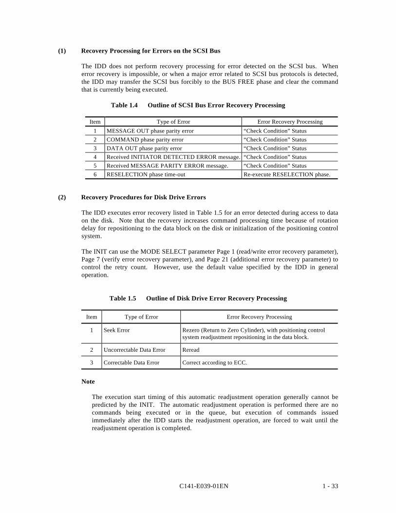
C141-E039-01EN 1 - 33
(1) Recovery Processing for Errors on the SCSI Bus
The IDD does not perform recovery processing for error detected on the SCSI bus. Whenerror recovery is impossible, or when a major error related to SCSI bus protocols is detected,the IDD may transfer the SCSI bus forcibly to the BUS FREE phase and clear the commandthat is currently being executed.
Table 1.4 Outline of SCSI Bus Error Recovery Processing
Item Type of Error Error Recovery Processing1 MESSAGE OUT phase parity error “Check Condition” Status2 COMMAND phase parity error “Check Condition” Status3 DATA OUT phase parity error “Check Condition” Status4 Received INITIATOR DETECTED ERROR message. “Check Condition” Status5 Received MESSAGE PARITY ERROR message. “Check Condition” Status6 RESELECTION phase time-out Re-execute RESELECTION phase.
(2) Recovery Procedures for Disk Drive Errors
The IDD executes error recovery listed in Table 1.5 for an error detected during access to dataon the disk. Note that the recovery increases command processing time because of rotationdelay for repositioning to the data block on the disk or initialization of the positioning controlsystem.
The INIT can use the MODE SELECT parameter Page 1 (read/write error recovery parameter),Page 7 (verify error recovery parameter), and Page 21 (additional error recovery parameter) tocontrol the retry count. However, use the default value specified by the IDD in generaloperation.
Table 1.5 Outline of Disk Drive Error Recovery Processing
Item Type of Error Error Recovery Processing
1 Seek Error Rezero (Return to Zero Cylinder), with positioning controlsystem readjustment repositioning in the data block.
2 Uncorrectable Data Error Reread
3 Correctable Data Error Correct according to ECC.
Note
The execution start timing of this automatic readjustment operation generally cannot bepredicted by the INIT. The automatic readjustment operation is performed there are nocommands being executed or in the queue, but execution of commands issuedimmediately after the IDD starts the readjustment operation, are forced to wait until thereadjustment operation is completed.
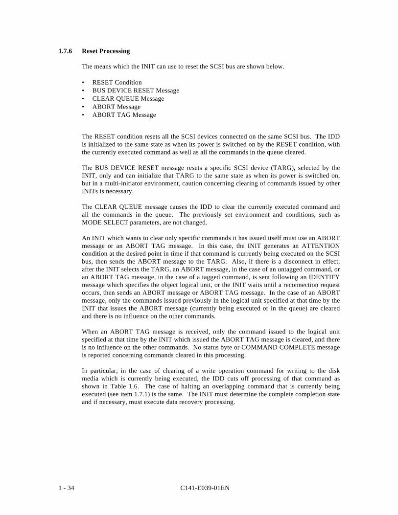
C141-E039-01EN1 - 34
1.7.6 Reset Processing
The means which the INIT can use to reset the SCSI bus are shown below.
• RESET Condition• BUS DEVICE RESET Message• CLEAR QUEUE Message• ABORT Message• ABORT TAG Message
The RESET condition resets all the SCSI devices connected on the same SCSI bus. The IDDis initialized to the same state as when its power is switched on by the RESET condition, withthe currently executed command as well as all the commands in the queue cleared.
The BUS DEVICE RESET message resets a specific SCSI device (TARG), selected by theINIT, only and can initialize that TARG to the same state as when its power is switched on,but in a multi-initiator environment, caution concerning clearing of commands issued by otherINITs is necessary.
The CLEAR QUEUE message causes the IDD to clear the currently executed command andall the commands in the queue. The previously set environment and conditions, such asMODE SELECT parameters, are not changed.
An INIT which wants to clear only specific commands it has issued itself must use an ABORTmessage or an ABORT TAG message. In this case, the INIT generates an ATTENTIONcondition at the desired point in time if that command is currently being executed on the SCSIbus, then sends the ABORT message to the TARG. Also, if there is a disconnect in effect,after the INIT selects the TARG, an ABORT message, in the case of an untagged command, oran ABORT TAG message, in the case of a tagged command, is sent following an IDENTIFYmessage which specifies the object logical unit, or the INIT waits until a reconnection requestoccurs, then sends an ABORT message or ABORT TAG message. In the case of an ABORTmessage, only the commands issued previously in the logical unit specified at that time by theINIT that issues the ABORT message (currently being executed or in the queue) are clearedand there is no influence on the other commands.
When an ABORT TAG message is received, only the command issued to the logical unitspecified at that time by the INIT which issued the ABORT TAG message is cleared, and thereis no influence on the other commands. No status byte or COMMAND COMPLETE messageis reported concerning commands cleared in this processing.
In particular, in the case of clearing of a write operation command for writing to the diskmedia which is currently being executed, the IDD cuts off processing of that command asshown in Table 1.6. The case of halting an overlapping command that is currently beingexecuted (see item 1.7.1) is the same. The INIT must determine the complete completion stateand if necessary, must execute data recovery processing.
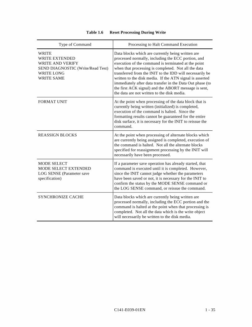
C141-E039-01EN 1 - 35
Table 1.6 Reset Processing During Write
Type of Command Processing to Halt Command Execution
WRITEWRITE EXTENDEDWRITE AND VERIFYSEND DIAGNOSTIC (Write/Read Test)WRITE LONGWRITE SAME
Data blocks which are currently being written areprocessed normally, including the ECC portion, andexecution of the command is terminated at the pointwhen that processing is completed. Not all the datatransferred from the INIT to the IDD will necessarily bewritten to the disk media. If the ATN signal is assertedimmediately after data transfer in the Data Out phase (tothe first ACK signal) and the ABORT message is sent,the data are not written to the disk media.
FORMAT UNIT At the point when processing of the data block that iscurrently being written (initialized) is completed,execution of the command is halted. Since theformatting results cannot be guaranteed for the entiredisk surface, it is necessary for the INIT to reissue thecommand.
REASSIGN BLOCKS At the point when processing of alternate blocks whichare currently being assigned is completed, execution ofthe command is halted. Not all the alternate blocksspecified for reassignment processing by the INIT willnecessarily have been processed.
MODE SELECTMODE SELECT EXTENDEDLOG SENSE (Parameter savespecification)
If a parameter save operation has already started, thatcommand is executed until it is completed. However,since the INIT cannot judge whether the parametershave been saved or not, it is necessary for the INIT toconfirm the status by the MODE SENSE command orthe LOG SENSE command, or reissue the command.
SYNCHRONIZE CACHE Data blocks which are currently being written areprocessed normally, including the ECC portion and thecommand is halted at the point when that processing iscompleted. Not all the data which is the write objectwill necessarily be written to the disk media.
C141-E039-01EN1 - 36
1.7.7 Fatal Hardware Errors
(1) Self-diagnostic Errors
If a fatal error is detected in the hardware in the initial self-diagnosis, in off-line self diagnosisor in on-line self-diagnosis (SEND DIAGNOSTIC command), rotation of the spindle motorwill be halted.
When in this state, the IDD reports the CHECK CONDITION status for all input/outputoperation requests except the REQUEST SENSE command. The sense data reported at thistime indicate HARDWARE ERROR [=4] / Diagnostic failure in component “nn” [=40-nn]. Itis necessary for the INIT either to generate a RESET condition or send a BUS DEVICERESET message and attempt to recover from the error state. For recommended procedures forerror recovery methods, see the explanation in 4.2 “INIT’s Error Recovery Methods(Recommended).” Furthermore, see 6.1.1 “Self-diagnostic Function” in “OEM ManualProduct Specifications/Installation Procedures.”
(2) Unrecoverable Hardware Errors
Limited to cases in which a fatal error occurs in the hardware during execution of a command,and termination processing such as a CHECK CONDITION status report cannot be executed,the IDD may halt rotation of the spindle motor.
After this state occurs, the IDD reports the CHECK CONDITION status for all input/outputoperation requests except the REQUEST SENSE command. The sense data reported at thistime indicate HARDWARE ERROR [=4] / Internal target failure [=44-nn]. If this state isreported continuously for input/output operation requests, it is necessary for the INIT togenerate a RESET condition or send a BUS DEVICE RESET message and attempt to recoverfrom the error state. For recommended procedures for error recovery methods by the INIT, seethe explanation in 4.2 “INIT’s Error Recovery Methods (Recommended).”
C141-E039-01EN 1 - 37
1.8 Data Block Addressing
1.8.1 Definition of Data Space
The IDD manages the data storage area on the disk drive in the following 2 types of dataspace.
• User Space: User Data Storage Area• System Space: IDD Exclusive Area
Of these 2 areas the user can clearly access the user space. The data format and defectmanagement methods in this space are the same and it is possible to access this space bylogical data block addressing described in item 1.8.2. System space is accessed by the IDDinternally when the power is switched on or during processing of specific commands, but itcannot be accessed directly by the user.
Fig. 1.4 shows the data space configuration on the disk drive. The number of cylindersallocated to user space can be specified by the user (MODE SELECT or MODE SELECTEXTENDED command).
A spare sector area (alternate area) for use as alternates for defective sectors is secured in userspace. The user can allocate the number of sectors in the final track of each cylinder and thenumber of cylinders in the user space (alternate use cylinders) as alternate area (by the MODESELECT or MODE SELECT EXTENDED command).
Alternate data blocks are allocated in defect sector units for defective sectors on the disk mediathrough internal IDD defect management. Through this defect management, the INIT canaccess all the logical data blocks in the user space as if they were error free.
For details concerning the data format on the disk media (cylinder configuration, track formatand sector format) and details concerning defect management techniques and alternate blockallocation techniques, Chapter 3 “Data Format” in the “Product Manual.” For an outline ofdefect management techniques, see “Disk Media Management Techniques” in Chapter 5 ofthis manual.
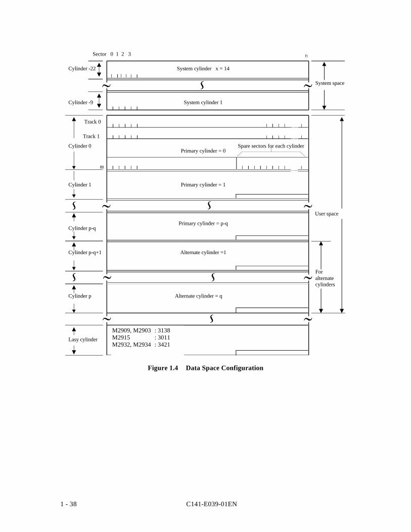
C141-E039-01EN1 - 38
M2909, M2903 : 3138M2915 : 3011M2932, M2934 : 3421
Cylinder -9
Cylinder -22
Cylinder 0
Cylinder 1
Cylinder p-q
Cylinder p-q+1
Sector 0 1 2 3
System cylinder x = 14
System cylinder 1
Primary cylinder = 0
Track 0
Track 1
Primary cylinder = p-q
Primary cylinder = 1
Alternate cylinder =1
Alternate cylinder = qCylinder p
Lasy cylinder
Foralternatecylinders
User space
System space
Spare sectors for each cylinder
Figure 1.4 Data Space Configuration
C141-E039-01EN 1 - 39
1.8.2 Logical Block Addressing
The IDD uses logical data block addressing which is not dependent on the disk drive’sphysical structure as the method of data access on the disk medium. The IDD addscorrespondence between each physical sector and each logical data clock address duringformatting. Access to the data on the disk medium is performed in logical data block unitsand the INIT specifies the logical data block address that is its object during access.
In logical data block addressing, specifying of a data block address is a function whichspecifies 2 continuous binary numbers for each drive. Furthermore, the INIT can know thelogical data block address range in the user space where specification is possible using theREAD CAPACITY command.
(1) User Space Logical Block Addresses
The top data block in the user space is made logical data block address “0,” then continuouslogical data block addresses are allocated to each data block until the final data block in theuser space.
The IDD makes cylinder 0, track 0 sector 0 the top logical data block, and allocatessubsequent logical data blocks in the order described below to addresses in ascending order.
1) Within the same track, logical data blocks are allocated to sector numbers in ascendingorder.
2) Within the same cylinder, excluding the final track, succeeding logical data blocks areallocated to the sectors in each track according to 1) in the ascending order of tracknumbers.
3) On the final track inside the same cylinder, succeeding logical data blocks are allocated tosectors except for spare sectors according to 1).
4) After all the allocation in 1) to 3) is completed within the same cylinder, succeedinglogical data blocks are allocated to the next cylinder beginning with track 0, according to1) to 3), and so on to each cylinder number in ascending order until the final cylinder(cylinder p-q in Fig. 1.4) in the user space, with the exception of alternate cylinders.
(2) Alternate Area
The alternate area in user space (spare sectors within each cylinder and alternate cylinders) areexcluded from the abovementioned logical data block addresses. Access to allocated sectorsas alternate blocks within the alternate area is performed automatically by the IDD’s defectmanagement (sector slip processing and alternate block processing), so it is not particularlynecessary for the user to access the alternate area. Also, data blocks in the alternate areacannot be clearly specified and accessed directly.

C141-E039-01EN 2 - 1
CHAPTER 2 DATA BUFFER MANAGEMENT
2.1 Data Buffer
2.2 Read-Ahead Cache Mechanism
2.3 Write Cache
In this chapter, the configuration of the data buffer with which the IDD is equipped, its operation andthe operation of the cache feature are described.
2.1 Data Buffer
2.1.1 Data Buffer Configuration and Basic Operation
The IDD is equipped with a 496 Kbyte data buffer, which makes it possible to efficientlyexecute data transfer operations between INIT (initiator) and a disk drive.
The data buffer, with a capacity of 512 KB, can be divided into a maximum of 16 cachesegments. Dividing of the data buffer is controlled by the MODE SELECT parameter (cachesegment parameter: Page code = 8).
Each data buffer is a 2-port configuration FIFO (First-In First-Out) ring buffer, with one portallocated for transfers with the disk media and the other port for data transfers with the SCSIbus. Mutual ports operate asynchronously and since it is possible to efficiently absorbvariations in data transfer speed between the ports, the INIT can perform data transferoperations with the IDD while being virtually unaware of differences between the SCSI busdata transfer rate and the disk drive data transfer rate.
Even if the data transfer capacity of the SCSI bus (INIT) is lower than the disk drive's datatransfer rate, the data buffer can perform data transfers to the system under optimumconditions without using sector interleave. Also, if the data transfer capacity of the SCSI bus(INIT) is higher than the disk drive's data transfer rate, it is possible to minimize theoccupancy time on the SCSI bus by accumulating an appropriate amount of data in the databuffer.
Only one cache segment of the divided data buffer is used by one command and the data in theother cache segments are held. The cache segment to be used is determine by the LRUalgorithm.
Fig. 2.1 shows the data buffer image.
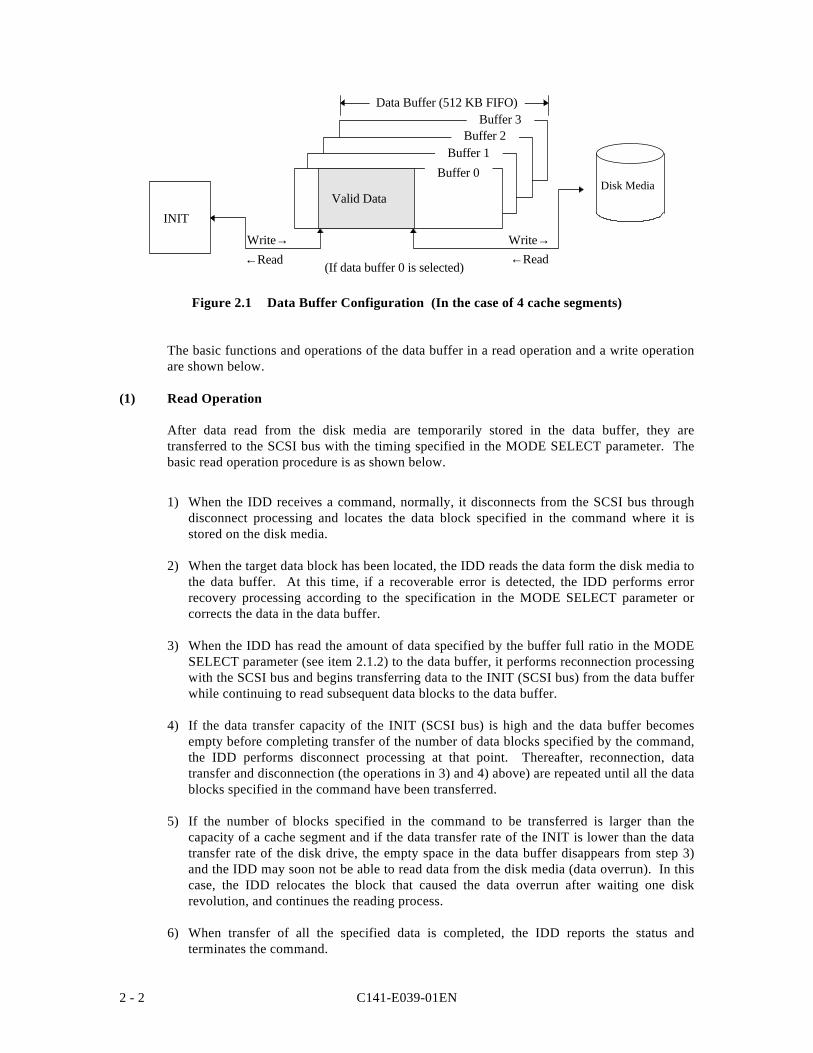
C141-E039-01EN2 - 2
←Read ←ReadWrite→
Buffer 3Buffer 2
Buffer 1Buffer 0
Valid Data
Write→
Disk Media
INIT
Data Buffer (512 KB FIFO)
(If data buffer 0 is selected)
Figure 2.1 Data Buffer Configuration (In the case of 4 cache segments)
The basic functions and operations of the data buffer in a read operation and a write operationare shown below.
(1) Read Operation
After data read from the disk media are temporarily stored in the data buffer, they aretransferred to the SCSI bus with the timing specified in the MODE SELECT parameter. Thebasic read operation procedure is as shown below.
1) When the IDD receives a command, normally, it disconnects from the SCSI bus throughdisconnect processing and locates the data block specified in the command where it isstored on the disk media.
2) When the target data block has been located, the IDD reads the data form the disk media tothe data buffer. At this time, if a recoverable error is detected, the IDD performs errorrecovery processing according to the specification in the MODE SELECT parameter orcorrects the data in the data buffer.
3) When the IDD has read the amount of data specified by the buffer full ratio in the MODESELECT parameter (see item 2.1.2) to the data buffer, it performs reconnection processingwith the SCSI bus and begins transferring data to the INIT (SCSI bus) from the data bufferwhile continuing to read subsequent data blocks to the data buffer.
4) If the data transfer capacity of the INIT (SCSI bus) is high and the data buffer becomesempty before completing transfer of the number of data blocks specified by the command,the IDD performs disconnect processing at that point. Thereafter, reconnection, datatransfer and disconnection (the operations in 3) and 4) above) are repeated until all the datablocks specified in the command have been transferred.
5) If the number of blocks specified in the command to be transferred is larger than thecapacity of a cache segment and if the data transfer rate of the INIT is lower than the datatransfer rate of the disk drive, the empty space in the data buffer disappears from step 3)and the IDD may soon not be able to read data from the disk media (data overrun). In thiscase, the IDD relocates the block that caused the data overrun after waiting one diskrevolution, and continues the reading process.
6) When transfer of all the specified data is completed, the IDD reports the status andterminates the command.
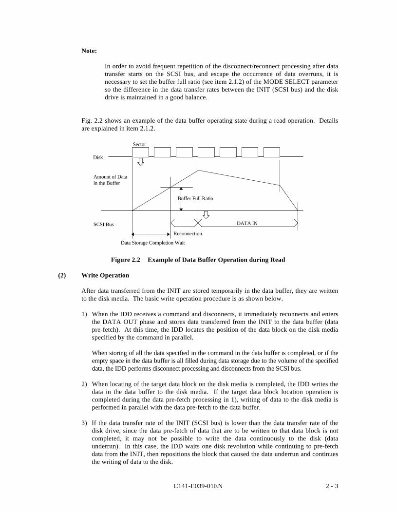
C141-E039-01EN 2 - 3
Note:
In order to avoid frequent repetition of the disconnect/reconnect processing after datatransfer starts on the SCSI bus, and escape the occurrence of data overruns, it isnecessary to set the buffer full ratio (see item 2.1.2) of the MODE SELECT parameterso the difference in the data transfer rates between the INIT (SCSI bus) and the diskdrive is maintained in a good balance.
Fig. 2.2 shows an example of the data buffer operating state during a read operation. Detailsare explained in item 2.1.2.
Data Storage Completion Wait
SCSI Bus
Sector
Disk
Amount of Datain the Buffer
Buffer Full Ratio
DATA IN
Reconnection
Figure 2.2 Example of Data Buffer Operation during Read
(2) Write Operation
After data transferred from the INIT are stored temporarily in the data buffer, they are writtento the disk media. The basic write operation procedure is as shown below.
1) When the IDD receives a command and disconnects, it immediately reconnects and entersthe DATA OUT phase and stores data transferred from the INIT to the data buffer (datapre-fetch). At this time, the IDD locates the position of the data block on the disk mediaspecified by the command in parallel.
When storing of all the data specified in the command in the data buffer is completed, or if theempty space in the data buffer is all filled during data storage due to the volume of the specifieddata, the IDD performs disconnect processing and disconnects from the SCSI bus.
2) When locating of the target data block on the disk media is completed, the IDD writes thedata in the data buffer to the disk media. If the target data block location operation iscompleted during the data pre-fetch processing in 1), writing of data to the disk media isperformed in parallel with the data pre-fetch to the data buffer.
3) If the data transfer rate of the INIT (SCSI bus) is lower than the data transfer rate of thedisk drive, since the data pre-fetch of data that are to be written to that data block is notcompleted, it may not be possible to write the data continuously to the disk (dataunderrun). In this case, the IDD waits one disk revolution while continuing to pre-fetchdata from the INIT, then repositions the block that caused the data underrun and continuesthe writing of data to the disk.
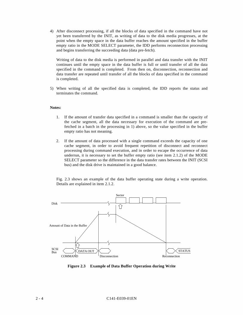
C141-E039-01EN2 - 4
4) After disconnect processing, if all the blocks of data specified in the command have notyet been transferred by the INIT, as writing of data to the disk media progresses, at thepoint when the empty space in the data buffer reaches the amount specified in the bufferempty ratio in the MODE SELECT parameter, the IDD performs reconnection processingand begins transferring the succeeding data (data pre-fetch).
Writing of data to the disk media is performed in parallel and data transfer with the INITcontinues until the empty space in the data buffer is full or until transfer of all the dataspecified in the command is completed. From then on, disconnection, reconnection anddata transfer are repeated until transfer of all the blocks of data specified in the commandis completed.
5) When writing of all the specified data is completed, the IDD reports the status andterminates the command.
Notes:
1. If the amount of transfer data specified in a command is smaller than the capacity ofthe cache segment, all the data necessary for execution of the command are pre-fetched in a batch in the processing in 1) above, so the value specified in the bufferempty ratio has not meaning.
2. If the amount of data processed with a single command exceeds the capacity of onecache segment, in order to avoid frequent repetition of disconnect and reconnectprocessing during command execution, and in order to escape the occurrence of dataunderrun, it is necessary to set the buffer empty ratio (see item 2.1.2) of the MODESELECT parameter so the difference in the data transfer rates between the INIT (SCSIbus) and the disk drive is maintained in a good balance.
Fig. 2.3 shows an example of the data buffer operating state during a write operation.Details are explained in item 2.1.2.
Amount of Data in the Buffer
SCSIBus
Sector
Disk
STATUS
ReconnectionDisconnectionDATA OUT
COMMAND
Figure 2.3 Example of Data Buffer Operation during Write
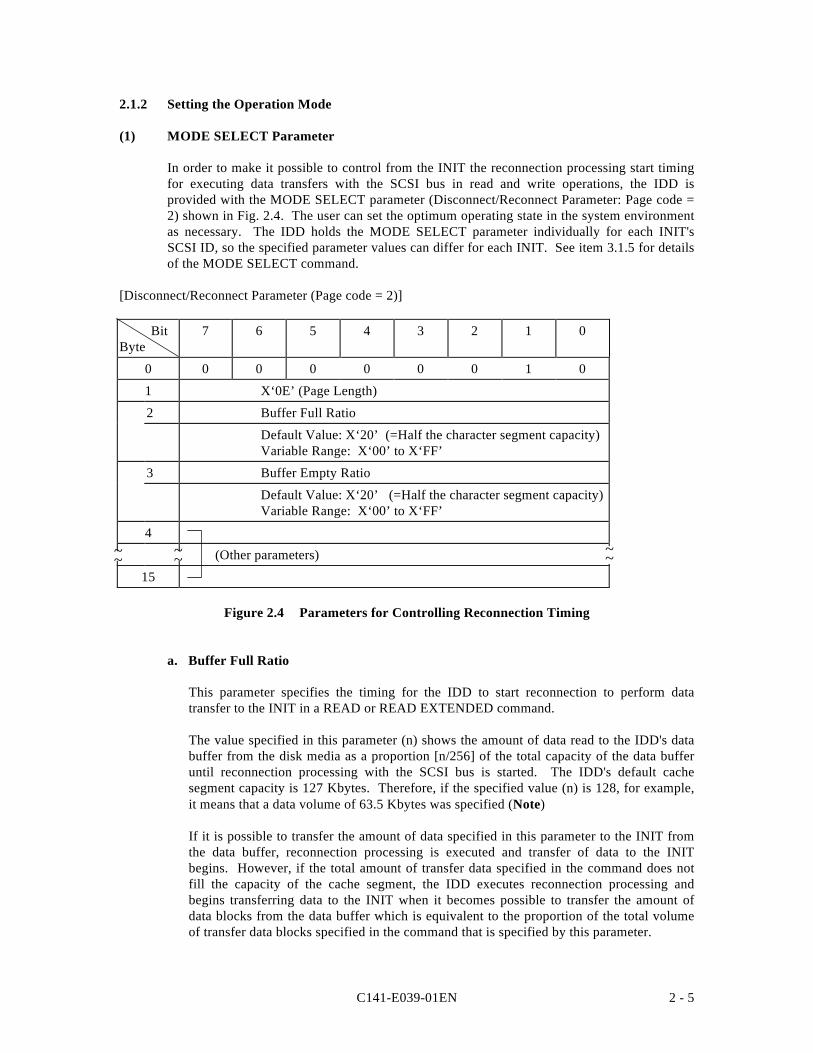
C141-E039-01EN 2 - 5
2.1.2 Setting the Operation Mode
(1) MODE SELECT Parameter
In order to make it possible to control from the INIT the reconnection processing start timingfor executing data transfers with the SCSI bus in read and write operations, the IDD isprovided with the MODE SELECT parameter (Disconnect/Reconnect Parameter: Page code =2) shown in Fig. 2.4. The user can set the optimum operating state in the system environmentas necessary. The IDD holds the MODE SELECT parameter individually for each INIT'sSCSI ID, so the specified parameter values can differ for each INIT. See item 3.1.5 for detailsof the MODE SELECT command.
[Disconnect/Reconnect Parameter (Page code = 2)]
BitByte
7 6 5 4 3 2 1 0
0 0 0 0 0 0 0 1 0
1 X‘0E’ (Page Length)
2 Buffer Full Ratio
Default Value: X‘20’ (=Half the character segment capacity)Variable Range: X‘00’ to X‘FF’
3 Buffer Empty Ratio
Default Value: X‘20’ (=Half the character segment capacity)Variable Range: X‘00’ to X‘FF’
4
(Other parameters)
15
Figure 2.4 Parameters for Controlling Reconnection Timing
a. Buffer Full Ratio
This parameter specifies the timing for the IDD to start reconnection to perform datatransfer to the INIT in a READ or READ EXTENDED command.
The value specified in this parameter (n) shows the amount of data read to the IDD's databuffer from the disk media as a proportion [n/256] of the total capacity of the data bufferuntil reconnection processing with the SCSI bus is started. The IDD's default cachesegment capacity is 127 Kbytes. Therefore, if the specified value (n) is 128, for example,it means that a data volume of 63.5 Kbytes was specified (Note)
If it is possible to transfer the amount of data specified in this parameter to the INIT fromthe data buffer, reconnection processing is executed and transfer of data to the INITbegins. However, if the total amount of transfer data specified in the command does notfill the capacity of the cache segment, the IDD executes reconnection processing andbegins transferring data to the INIT when it becomes possible to transfer the amount ofdata blocks from the data buffer which is equivalent to the proportion of the total volumeof transfer data blocks specified in the command that is specified by this parameter.
~~ ~~~~
C141-E039-01EN2 - 6
For example, if a read operation of 16 blocks with a logical data block length of 512 bytes(8 Kbytes) is requested, when the value specified in this parameter is 32, reconnectionprocessing is performed when it becomes possible to transfer 2 blocks of data [16 x(32/256)], from the data buffer.
b. Buffer Empty Ratio
This parameter specifies the timing for the IDD to start reconnection when it is requestedby the INIT to transfer data in the WRITE, WRITE EXTENDED or WRITE ANDVERIFY command. In a write operation, after the IDD receives a command, the IDDbegins transferring data (data pre-fetch) while locating the position of the target datablocks on the disk media in parallel. Therefore, if the total number of bytes of dataspecified in the command is less than the capacity of a cache segment, all the data are pre-fetched in a batch, so the specification in this parameter is not applied.
The value specified in this parameter (n) indicates a proportion of the total data buffercapacity of the IDD when the buffer is empty [n/256]. For example, if the specified value(n) is 128 and the number of cache segments is 4 (this is the default value), the size of theempty space in the buffer is specified as 63.5 Kbytes. (Note)
While the IDD is writing data to the disk media, it is using the data pre-fetched to the databuffer in order and when the empty space in the data buffer reaches the amount specifiedin this parameter, it executes reconnection processing, requesting transfer of thesucceeding data. However, if the number of data blocks remaining to be transferredaccording to the command being executed does not reach the amount of data specified inthis parameter, the IDD executes reconnection processing at the point when the number ofdata blocks remaining in the data buffer's empty space reaches the specified number ofdata blocks and requests transfer of the succeeding data.
Note:
If the value specified for the "buffer full ratio" or the "buffer empty ratio" is not withindouble the integral boundary of the logical data block length, the IDD rounds up thespecified value which is the nearest data block boundary. Also, if zero is specified in anyof these parameters, the IDD treats that parameter as though 1 logical data block has beenspecified.
C141-E039-01EN 2 - 7
2.2 Look-Ahead Cache Feature
In order to use the data buffer more effectively and improve the disk drive's effective accessspeed, the IDD is equipped with a simple cache feature called a "Look-Ahead Cache Feature."The Look-Ahead cache feature is an effective, simple cache function for an INIT which readsdata block groups on the disk media sequentially using multiple commands.
2.2.1 Caching Operation
When the IDD is executing a READ command or a READ EXTENDED command, it readsthe requested data from the disk media and transfers it to the INIT while at the same timereading (looking ahead at) data blocks which are subsequent to the final logical data blockspecified in that command to the data buffer. Then, when a READ command or READEXTENDED command issued later specifies any of those Look-Ahead data blocks, the IDDtransfers those data directly to the INIT from the data buffer without accessing the disk media.In this way, when continuous logical data block groups are read sequentially by multiplecommands, mechanical access operations can be eliminated and effective access time greatlyreduced.
An INIT can prohibit the operation of this Look-Ahead cache feature by setting the cachingparameter described in item 2.2.2.
(1) Caching Object Commands
Commands which execute caching operations are the commands shown below:
• READ• READ EXTENDED
If all the data block groups which are objects of the processing specified in these commands,or a portion of the data blocks, including the top logical data block specified in thesecommands are relevant data (See item (2)) for caching in the data buffer (if they hit), when theIDD receives a command and performs disconnect processing, it immediately reconnects andsends the data on the data buffer which can be transferred to the INIT. The caching operationcan be disabled by the FUA bit of the READ EXTENDED command. If "1" is specified in theFUA bit, the IDD reads data from the disk media.
On the other hand, if the top logical data block specified in a command is not relevant data forcaching in the data buffer (if they miss), reading of data is performed from the disk mediausing the oldest cache segment (selected by time stamp).
(2) Data which are Objects of Caching
Data which exist in the data buffer and which are objects of caching in item (1) (data which arenot accessed from the disk media but are transferred to the INIT from the data buffer) are asdescribed below.
a) Data read by a READ or a READ EXTENDED command and which have been read to thedata buffer by Look-Ahead are data which are objects of caching. Depending on thetiming for halting Look-Ahead, it is possible that data read by the READ command will beoverwritten by Look-Ahead.
C141-E039-01EN2 - 8
b) Data which have been hit by the READ or READ EXTENDED command and transferredto the INIT once are also objects of caching as long as they are not invalidated.
c) Data transferred from the INIT and written to the disk media by the WRITE, WRITEEXTENDED, WRITE AND VERIFY or other data writing command are not objects ofcaching.
3) Disabling Caching Data
Various data which are objects of caching in the data buffer are disabled in the followingcases.
a) If any of the following commands is issued for the same data block as data which are theobject of caching, that data block ceases to be an object of caching.
• WRITE • WRITE AND VERIFY• WRITE EXTENDED
b) If any of the following commands is issued, all the data which are objects of caching aredisabled.
• FORMAT UNIT • RECEIVE DIAGNOSTIC RESULTS• MODE SELECT • SEND DIAGNOSTIC• MODE SELECT EXTENDED • START/STOP UNIT• READ DEFECT DATA • WRITE BUFFER• READ LONG • WRITE LONG• REASSIGN BLOCKS • WRITE SAME
c) If the data buffer where data which are objects of caching are stored is used by any of thefollowing commands, the data existing in that data buffer which are objects of caching aredisabled.
• READ • WRITE• READ EXTENDED • WRITE EXTENDED• PRE-FETCH • WRITE AND VERIFY• VERIFY
d) If any of the following events occurs, all the data which are objects of caching aredisabled.
• If a RESET condition occurs on the SCSI bus.• If a BUS DEVICE RESET message is issued by any INIT.• If automatic alternate processing is executed.
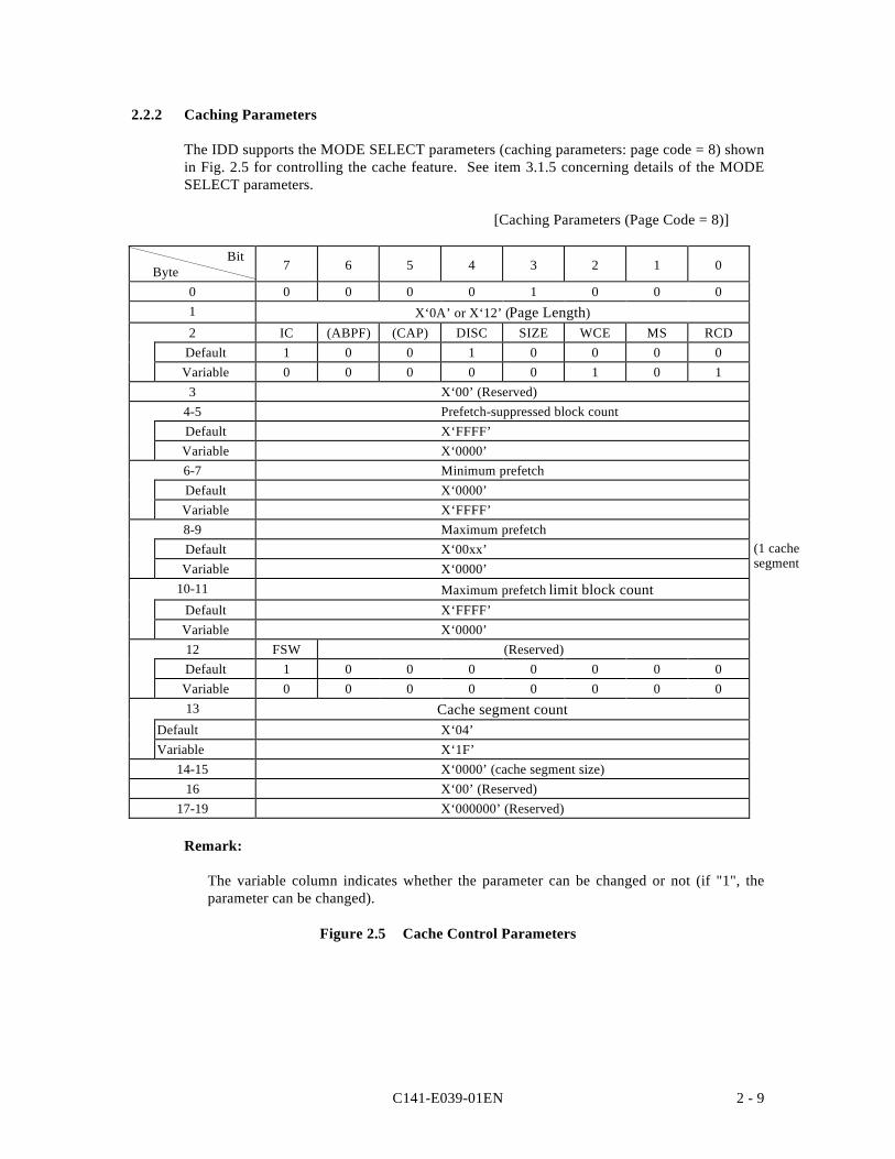
C141-E039-01EN 2 - 9
2.2.2 Caching Parameters
The IDD supports the MODE SELECT parameters (caching parameters: page code = 8) shownin Fig. 2.5 for controlling the cache feature. See item 3.1.5 concerning details of the MODESELECT parameters.
[Caching Parameters (Page Code = 8)]
Bit Byte 7 6 5 4 3 2 1 0
0 0 0 0 0 1 0 0 01 X‘0A’ or X‘12’ (Page Length)2 IC (ABPF) (CAP) DISC SIZE WCE MS RCD
Default 1 0 0 1 0 0 0 0Variable 0 0 0 0 0 1 0 1
3 X‘00’ (Reserved)4-5 Prefetch-suppressed block countDefault X‘FFFF’Variable X‘0000’6-7 Minimum prefetchDefault X‘0000’Variable X‘FFFF’8-9 Maximum prefetchDefault X‘00xx’Variable X‘0000’
10-11 Maximum prefetch limit block countDefault X‘FFFF’Variable X‘0000’12 FSW (Reserved)Default 1 0 0 0 0 0 0 0Variable 0 0 0 0 0 0 0 013 Cache segment count
Default X‘04’Variable X‘1F’
14-15 X‘0000’ (cache segment size)16 X‘00’ (Reserved)
17-19 X‘000000’ (Reserved)
Remark:
The variable column indicates whether the parameter can be changed or not (if "1", theparameter can be changed).
Figure 2.5 Cache Control Parameters
(1 cachesegment
C141-E039-01EN2 - 10
2.2.3 Look-Ahead Operation, Look-Ahead Volume
1) Excluding the conditions in 3) and 4) for the amount of data specified as the minimum pre-fetch volume, data are read for look-ahead irrespective of track boundaries or cylinderboundaries. Commands which are already in the queue or commands which are newlyreceived while a look-ahead operation is in progress, are executed after the look-aheadoperation is completed. However, if the new command is a READ or READ EXTENDEDcommand, and it is a command in which the first specified logical data block is asequential access data block, the command is executed without the look-ahead operationbeing halted. When a newly received command is a command which is not the object ofcaching, that command is executed immediately in parallel with a look-ahead operation.Also, in the case of a command which disables all data which are objects of caching (seeitem 2.2.1 (3)), the look-ahead operation is halted and that command is executedimmediately.
2) When commands exist in the queue, the look-ahead operation is halted at the point whenreading of the specified amount of data at the minimum pre-fetch volume is completed,then execution of the new command starts. When there are no commands that need to benewly executed, the data look-ahead operation is continued, even after the volume of dataspecified as the minimum amount of pre-fetch data have been read, until one of thefollowing conditions, 1), 3) or 4), occurs.
• When "1" is specified in the DISC bit, if look-ahead of data equal in volume to a cachesegment is completed.
• When "0" is specified in the DISC bit, if look-ahead of all the data is completed up tothe track boundary or the cylinder boundary.
3) During a data look-ahead operation, when any error occurs, the data look-ahead operationis terminated at that point (retry is not executed).
4) When a RESET condition occurs on the SCSI bus, or when any INIT issues a BUSDEVICE RESET message, the look-ahead operation is terminated at that point and all thelook-ahead data stored in the data buffer are invalidated.
5) During a look-ahead operation, if "sector slip processing" is applied, or defective sectorsexist in the same cylinder to which "alternate processing" is applicable, the look-aheadoperation is continued without interruption.
C141-E039-01EN 2 - 11
2.3 Write Cache
The IDD is equipped with a Write cache function in order to reduce the INIT's commandprocessing time. If that operation is permitted by the MODE SELECT command (cachingparameters: Page code = 8, WCE bit), at the point when the IDD completes the transfer of alldata specified in the WRITE or WRITE EXTENDED command, it reports the GOODstatement and terminates the command.
Note:
If the Write cache function is permitted, data transferred form the INIT by a WRITE orWRITE EXTENDED command are written to the disk media after the GOOD status isreported, so when an unrecoverable write error is detected in that write operation, sensedata are generated. When those sense data are being held, the IDD ordinarily responds tothe command that is executed next by a "CHECK" status (deferred error), notifying theINIT that sense data are being held. However, ordinarily, it is troublesome for the INIT toretry when there is an unrecoverable error in a Write cache operation, so adequate cautionshould be exercised when using this function.

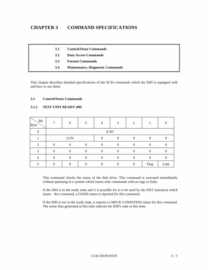
C141-E039-01EN 3 - 1
CHAPTER 3 COMMAND SPECIFICATIONS
3.1 Control/Sense Commands
3.2 Data Access Commands
3.3 Format Commands
3.4 Maintenance, Diagnostic Commands
This chapter describes detailed specifications of the SCSI commands which the IDD is equipped withand how to use them.
3.1 Control/Sense Commands
3.1.1 TEST UNIT READY (00)
BitByte 7 6 5 4 3 2 1 0
0 X‘00’
1 LUN 0 0 0 0 0
2 0 0 0 0 0 0 0 0
3 0 0 0 0 0 0 0 0
4 0 0 0 0 0 0 0 0
5 0 0 0 0 0 0 Flag Link
This command checks the status of the disk drive. This command is executed immediatelywithout queueing in a system which issues only commands with no tags or links.
If the IDD is in the ready state and it is possible for it to be used by the INIT (initiator) whichissues this command, a GOOD status is reported for this command.
If the IDD is not in the ready state, it reports a CHECK CONDITION status for this command.The sense data generated at this time indicate the IDD's state at this time.
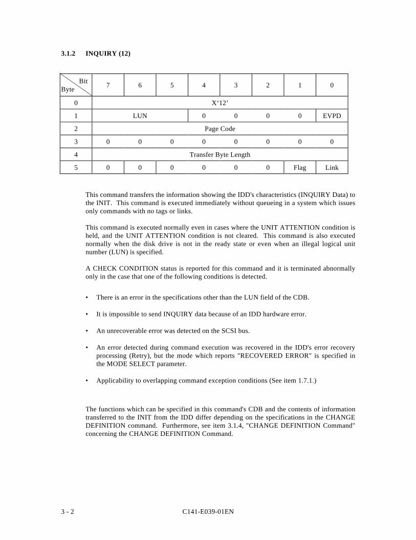
C141-E039-01EN3 - 2
3.1.2 INQUIRY (12)
BitByte 7 6 5 4 3 2 1 0
0 X‘12’
1 LUN 0 0 0 0 EVPD
2 Page Code
3 0 0 0 0 0 0 0 0
4 Transfer Byte Length
5 0 0 0 0 0 0 Flag Link
This command transfers the information showing the IDD's characteristics (INQUIRY Data) tothe INIT. This command is executed immediately without queueing in a system which issuesonly commands with no tags or links.
This command is executed normally even in cases where the UNIT ATTENTION condition isheld, and the UNIT ATTENTION condition is not cleared. This command is also executednormally when the disk drive is not in the ready state or even when an illegal logical unitnumber (LUN) is specified.
A CHECK CONDITION status is reported for this command and it is terminated abnormallyonly in the case that one of the following conditions is detected.
• There is an error in the specifications other than the LUN field of the CDB.
• It is impossible to send INQUIRY data because of an IDD hardware error.
• An unrecoverable error was detected on the SCSI bus.
• An error detected during command execution was recovered in the IDD's error recoveryprocessing (Retry), but the mode which reports "RECOVERED ERROR" is specified inthe MODE SELECT parameter.
• Applicability to overlapping command exception conditions (See item 1.7.1.)
The functions which can be specified in this command's CDB and the contents of informationtransferred to the INIT from the IDD differ depending on the specifications in the CHANGEDEFINITION command. Furthermore, see item 3.1.4, "CHANGE DEFINITION Command"concerning the CHANGE DEFINITION Command.
C141-E039-01EN 3 - 3
If bytes 1 and 0, the "EVPD (enable vital product data)" bits, and byte 2, the "Page code" fieldin the CDB are enabled only in the case that transfer of the SCSI-2 mode's INQUIRY data isspecified. In the case of the SCSI-1/CCS Mode, zero must be set in these bits and in this field.
If the specification in the "EVPD" bits is "0," the IDD transfers the standard INQUIRY data,mentioned later, to the INIT. On the other hand, if "1" is specified in the "EVPD" bits,information called VPD (vital product data) is transferred to the INIT.
Byte 2 of the CDB, the "Page code" field specifies the type of VPD information that should betransferred to the INIT if the "EVPD" bits are "1." If the "EVPD" bits are "0," zero must bespecified in this field.
Byte 4 of the CDB, the "Transfer Byte Length" field, shows the number of bytes of standardINQUIRY data or VPD information that the INIT can receive by this command. The IDDtransfers data with the byte length specified in the "Transfer Byte Length" field, or the bytelength in the standard INQUIRY data or VPD information which it is holding, whichever hasthe smallest number of bytes, to the INIT. When zero is specified in the "Transfer ByteLength" field, this command is normally terminated without anything being transferred.
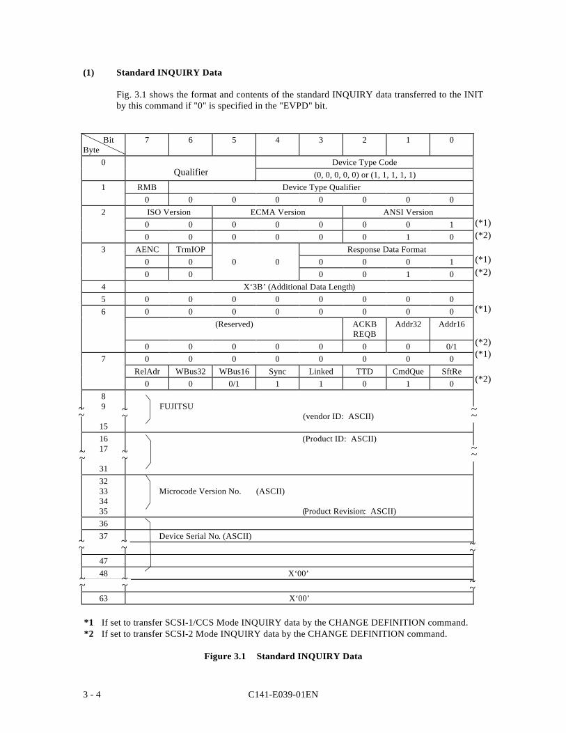
C141-E039-01EN3 - 4
(1) Standard INQUIRY Data
Fig. 3.1 shows the format and contents of the standard INQUIRY data transferred to the INITby this command if "0" is specified in the "EVPD" bit.
BitByte
7 6 5 4 3 2 1 0
0 Device Type Code(0, 0, 0, 0, 0) or (1, 1, 1, 1, 1)
1 RMB Device Type Qualifier0 0 0 0 0 0 0 0
2 ISO Version ECMA Version ANSI Version0 0 0 0 0 0 0 10 0 0 0 0 0 1 0
3 AENC TrmIOP Response Data Format0 0 0 0 0 0 0 10 0 0 0 1 0
4 X‘3B’ (Additional Data Length)5 0 0 0 0 0 0 0 06 0 0 0 0 0 0 0 0
(Reserved) ACKBREQB
Addr32 Addr16
0 0 0 0 0 0 0 0/17 0 0 0 0 0 0 0 0
RelAdr WBus32 WBus16 Sync Linked TTD CmdQue SftRe0 0 0/1 1 1 0 1 0
89
15
FUJITSU (vendor ID: ASCII)
1617
31
(Product ID: ASCII)
32333435
Microcode Version No. (ASCII)
(Product Revision: ASCII)3637 Device Serial No. (ASCII)
4748 X‘00’
63 X‘00’
*1 If set to transfer SCSI-1/CCS Mode INQUIRY data by the CHANGE DEFINITION command.*2 If set to transfer SCSI-2 Mode INQUIRY data by the CHANGE DEFINITION command.
Figure 3.1 Standard INQUIRY Data
~~~~
(*2)
(*2)
(*2)(*1)
Qualifier
~~
~~
~~ ~~
(*2)
(*1)
(*1)
(*1)
~~ ~~
~~ ~~
~~
~~
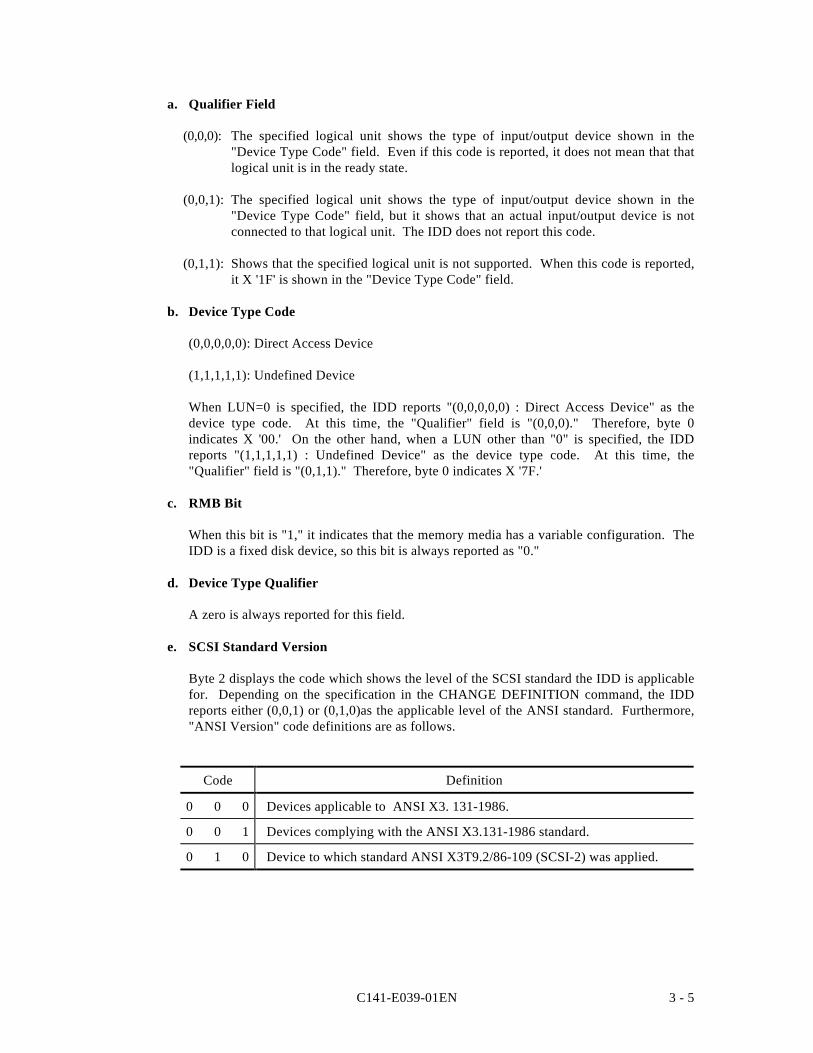
C141-E039-01EN 3 - 5
a. Qualifier Field
(0,0,0): The specified logical unit shows the type of input/output device shown in the"Device Type Code" field. Even if this code is reported, it does not mean that thatlogical unit is in the ready state.
(0,0,1): The specified logical unit shows the type of input/output device shown in the"Device Type Code" field, but it shows that an actual input/output device is notconnected to that logical unit. The IDD does not report this code.
(0,1,1): Shows that the specified logical unit is not supported. When this code is reported,it X '1F' is shown in the "Device Type Code" field.
b. Device Type Code
(0,0,0,0,0): Direct Access Device
(1,1,1,1,1): Undefined Device
When LUN=0 is specified, the IDD reports "(0,0,0,0,0) : Direct Access Device" as thedevice type code. At this time, the "Qualifier" field is "(0,0,0)." Therefore, byte 0indicates X '00.' On the other hand, when a LUN other than "0" is specified, the IDDreports "(1,1,1,1,1) : Undefined Device" as the device type code. At this time, the"Qualifier" field is "(0,1,1)." Therefore, byte 0 indicates X '7F.'
c. RMB Bit
When this bit is "1," it indicates that the memory media has a variable configuration. TheIDD is a fixed disk device, so this bit is always reported as "0."
d. Device Type Qualifier
A zero is always reported for this field.
e. SCSI Standard Version
Byte 2 displays the code which shows the level of the SCSI standard the IDD is applicablefor. Depending on the specification in the CHANGE DEFINITION command, the IDDreports either (0,0,1) or (0,1,0)as the applicable level of the ANSI standard. Furthermore,"ANSI Version" code definitions are as follows.
Code Definition
0 0 0 Devices applicable to ANSI X3. 131-1986.
0 0 1 Devices complying with the ANSI X3.131-1986 standard.
0 1 0 Device to which standard ANSI X3T9.2/86-109 (SCSI-2) was applied.
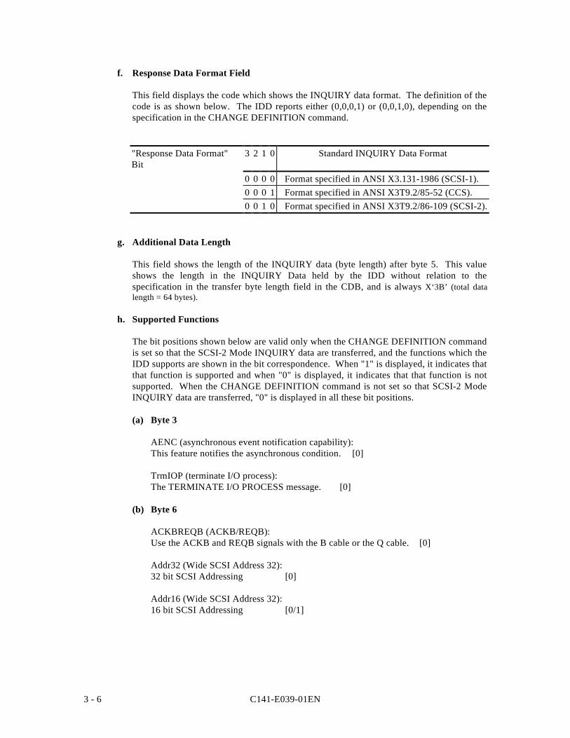
C141-E039-01EN3 - 6
f. Response Data Format Field
This field displays the code which shows the INQUIRY data format. The definition of thecode is as shown below. The IDD reports either (0,0,0,1) or (0,0,1,0), depending on thespecification in the CHANGE DEFINITION command.
"Response Data Format"Bit
3 2 1 0 Standard INQUIRY Data Format
0 0 0 0 Format specified in ANSI X3.131-1986 (SCSI-1).0 0 0 1 Format specified in ANSI X3T9.2/85-52 (CCS).0 0 1 0 Format specified in ANSI X3T9.2/86-109 (SCSI-2).
g. Additional Data Length
This field shows the length of the INQUIRY data (byte length) after byte 5. This valueshows the length in the INQUIRY Data held by the IDD without relation to thespecification in the transfer byte length field in the CDB, and is always X‘3B’ (total datalength = 64 bytes).
h. Supported Functions
The bit positions shown below are valid only when the CHANGE DEFINITION commandis set so that the SCSI-2 Mode INQUIRY data are transferred, and the functions which theIDD supports are shown in the bit correspondence. When "1" is displayed, it indicates thatthat function is supported and when "0" is displayed, it indicates that that function is notsupported. When the CHANGE DEFINITION command is not set so that SCSI-2 ModeINQUIRY data are transferred, "0" is displayed in all these bit positions.
(a) Byte 3
AENC (asynchronous event notification capability):This feature notifies the asynchronous condition. [0]
TrmIOP (terminate I/O process):The TERMINATE I/O PROCESS message. [0]
(b) Byte 6
ACKBREQB (ACKB/REQB):Use the ACKB and REQB signals with the B cable or the Q cable. [0]
Addr32 (Wide SCSI Address 32):32 bit SCSI Addressing [0]
Addr16 (Wide SCSI Address 32):16 bit SCSI Addressing [0/1]
C141-E039-01EN 3 - 7
(c) Byte 7
RelAdr (relative addressing):Relative logic block addressing [0]
WBus32 (32-bit wide data transfer) :Data transfer on a 4-byte bus [0]
WBus16 (16-bit wide data transfer) :Data transfer on a 2-byte bus [0/1]
Sync (synchronous data transfer):Data transfer in the synchronous mode [1]
Linked (linked command):Command link function [1]
TTD (target transfer disable):TARGET TRANSFER DISABLE Message [0]
Cmd/Que (command queuing):Tagged command queuing feature [1]
SftRe (soft reset):"soft" RESET condition [0]
i. Vendor ID Field
This field indicates the name of the product's supplier in left-justified ASCII code, andalways displays FUJITSU. The unused right end is space for the ASCII code.
j. Product ID Field
The product's model name is displayed in left-justified ASCII code in this field. Themodel name display is one of the following.
k. Product Revision Field
The IDD's microcode version number is displayed in ASCII code in this field.
l. Device Serial Number Field
The value following byte 4 of the device serial number in the VPD information isindicated in this field. Higher order digits which do not contain valid numbers are filledwith ASCII code spaces (X '20'). After byte 48, all the positions contain "00."
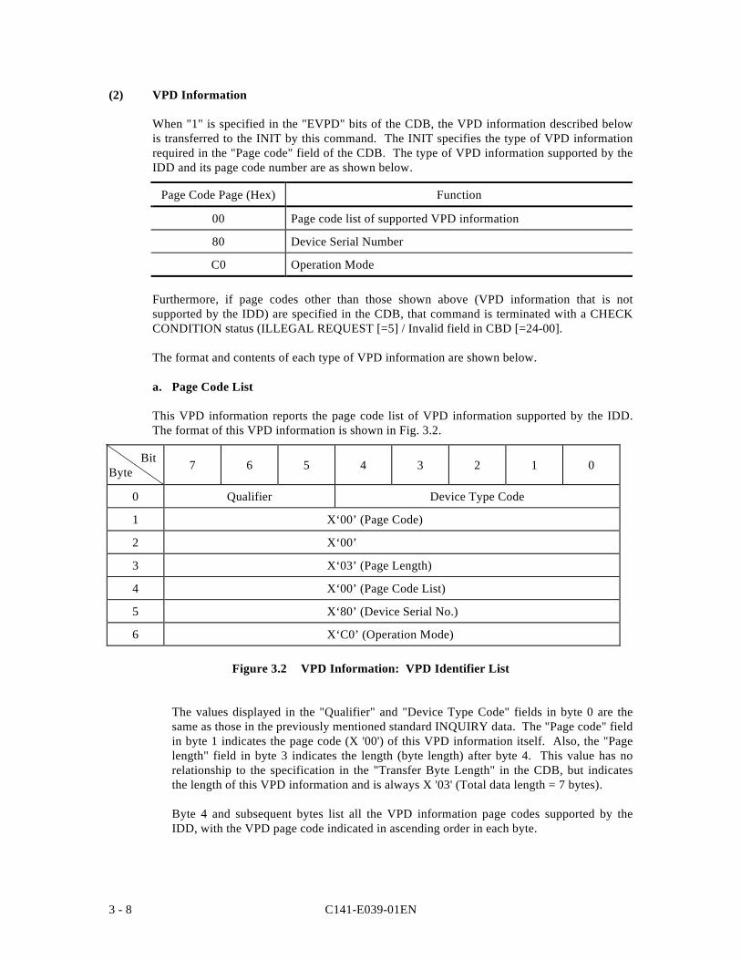
C141-E039-01EN3 - 8
(2) VPD Information
When "1" is specified in the "EVPD" bits of the CDB, the VPD information described belowis transferred to the INIT by this command. The INIT specifies the type of VPD informationrequired in the "Page code" field of the CDB. The type of VPD information supported by theIDD and its page code number are as shown below.
Page Code Page (Hex) Function
00 Page code list of supported VPD information
80 Device Serial Number
C0 Operation Mode
Furthermore, if page codes other than those shown above (VPD information that is notsupported by the IDD) are specified in the CDB, that command is terminated with a CHECKCONDITION status (ILLEGAL REQUEST [=5] / Invalid field in CBD [=24-00].
The format and contents of each type of VPD information are shown below.
a. Page Code List
This VPD information reports the page code list of VPD information supported by the IDD.The format of this VPD information is shown in Fig. 3.2.
BitByte 7 6 5 4 3 2 1 0
0 Qualifier Device Type Code
1 X‘00’ (Page Code)
2 X‘00’
3 X‘03’ (Page Length)
4 X‘00’ (Page Code List)
5 X‘80’ (Device Serial No.)
6 X‘C0’ (Operation Mode)
Figure 3.2 VPD Information: VPD Identifier List
The values displayed in the "Qualifier" and "Device Type Code" fields in byte 0 are thesame as those in the previously mentioned standard INQUIRY data. The "Page code" fieldin byte 1 indicates the page code (X '00') of this VPD information itself. Also, the "Pagelength" field in byte 3 indicates the length (byte length) after byte 4. This value has norelationship to the specification in the "Transfer Byte Length" in the CDB, but indicatesthe length of this VPD information and is always X '03' (Total data length = 7 bytes).
Byte 4 and subsequent bytes list all the VPD information page codes supported by theIDD, with the VPD page code indicated in ascending order in each byte.
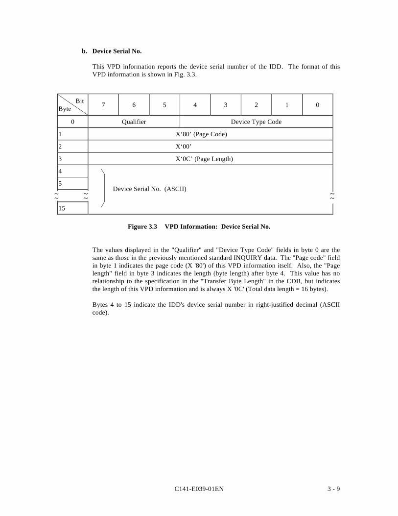
C141-E039-01EN 3 - 9
b. Device Serial No.
This VPD information reports the device serial number of the IDD. The format of thisVPD information is shown in Fig. 3.3.
BitByte 7 6 5 4 3 2 1 0
0 Qualifier Device Type Code
1 X‘80’ (Page Code)
2 X‘00’
3 X‘0C’ (Page Length)
4
5
15
Figure 3.3 VPD Information: Device Serial No.
The values displayed in the "Qualifier" and "Device Type Code" fields in byte 0 are thesame as those in the previously mentioned standard INQUIRY data. The "Page code" fieldin byte 1 indicates the page code (X '80') of this VPD information itself. Also, the "Pagelength" field in byte 3 indicates the length (byte length) after byte 4. This value has norelationship to the specification in the "Transfer Byte Length" in the CDB, but indicatesthe length of this VPD information and is always X '0C' (Total data length = 16 bytes).
Bytes 4 to 15 indicate the IDD's device serial number in right-justified decimal (ASCIIcode).
~~ ~~ ~~Device Serial No. (ASCII)
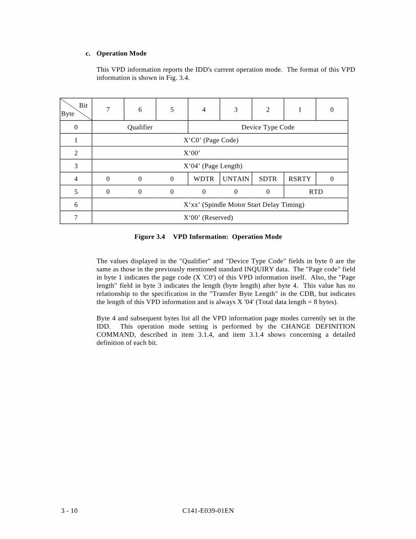
C141-E039-01EN3 - 10
c. Operation Mode
This VPD information reports the IDD's current operation mode. The format of this VPDinformation is shown in Fig. 3.4.
BitByte 7 6 5 4 3 2 1 0
0 Qualifier Device Type Code
1 X‘C0’ (Page Code)
2 X‘00’
3 X‘04’ (Page Length)
4 0 0 0 WDTR UNTAIN SDTR RSRTY 0
5 0 0 0 0 0 0 RTD
6 X‘xx’ (Spindle Motor Start Delay Timing)
7 X‘00’ (Reserved)
Figure 3.4 VPD Information: Operation Mode
The values displayed in the "Qualifier" and "Device Type Code" fields in byte 0 are thesame as those in the previously mentioned standard INQUIRY data. The "Page code" fieldin byte 1 indicates the page code (X 'C0') of this VPD information itself. Also, the "Pagelength" field in byte 3 indicates the length (byte length) after byte 4. This value has norelationship to the specification in the "Transfer Byte Length" in the CDB, but indicatesthe length of this VPD information and is always X '04' (Total data length = 8 bytes).
Byte 4 and subsequent bytes list all the VPD information page modes currently set in theIDD. This operation mode setting is performed by the CHANGE DEFINITIONCOMMAND, described in item 3.1.4, and item 3.1.4 shows concerning a detaileddefinition of each bit.
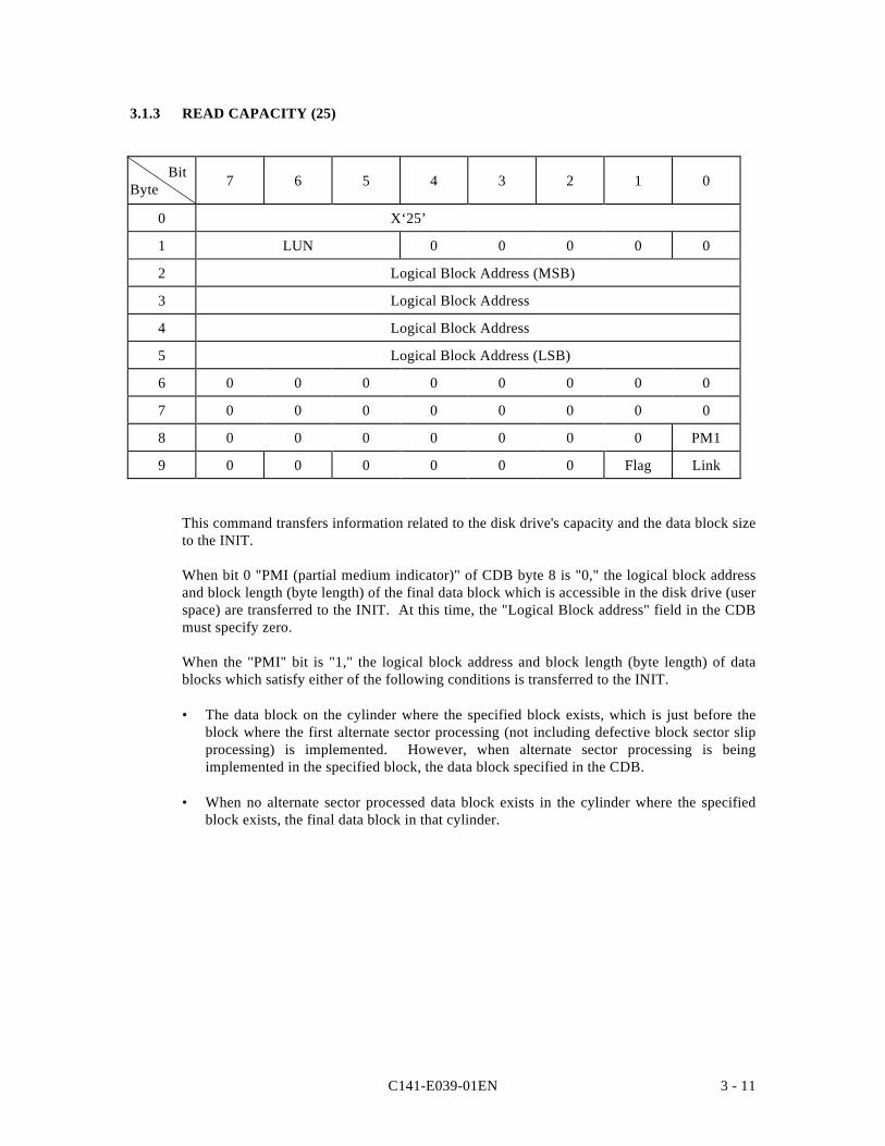
C141-E039-01EN 3 - 11
3.1.3 READ CAPACITY (25)
BitByte 7 6 5 4 3 2 1 0
0 X‘25’
1 LUN 0 0 0 0 0
2 Logical Block Address (MSB)
3 Logical Block Address
4 Logical Block Address
5 Logical Block Address (LSB)
6 0 0 0 0 0 0 0 0
7 0 0 0 0 0 0 0 0
8 0 0 0 0 0 0 0 PM1
9 0 0 0 0 0 0 Flag Link
This command transfers information related to the disk drive's capacity and the data block sizeto the INIT.
When bit 0 "PMI (partial medium indicator)" of CDB byte 8 is "0," the logical block addressand block length (byte length) of the final data block which is accessible in the disk drive (userspace) are transferred to the INIT. At this time, the "Logical Block address" field in the CDBmust specify zero.
When the "PMI" bit is "1," the logical block address and block length (byte length) of datablocks which satisfy either of the following conditions is transferred to the INIT.
• The data block on the cylinder where the specified block exists, which is just before theblock where the first alternate sector processing (not including defective block sector slipprocessing) is implemented. However, when alternate sector processing is beingimplemented in the specified block, the data block specified in the CDB.
• When no alternate sector processed data block exists in the cylinder where the specifiedblock exists, the final data block in that cylinder.
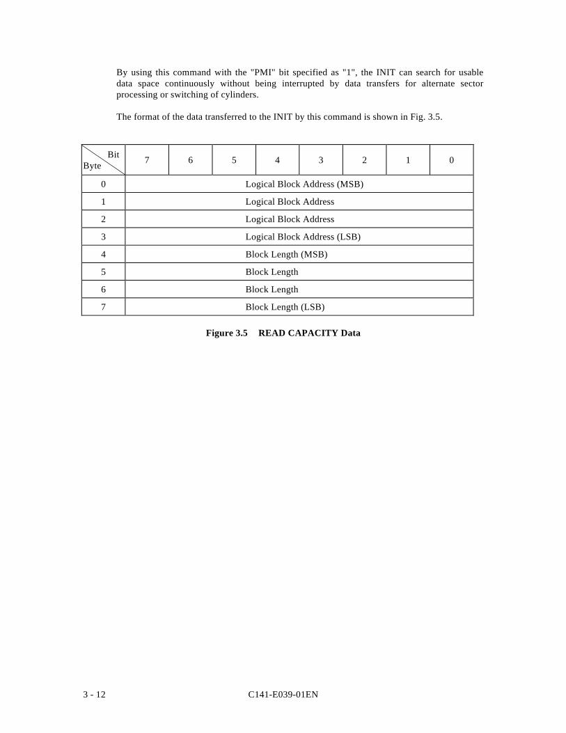
C141-E039-01EN3 - 12
By using this command with the "PMI" bit specified as "1", the INIT can search for usabledata space continuously without being interrupted by data transfers for alternate sectorprocessing or switching of cylinders.
The format of the data transferred to the INIT by this command is shown in Fig. 3.5.
BitByte 7 6 5 4 3 2 1 0
0 Logical Block Address (MSB)
1 Logical Block Address
2 Logical Block Address
3 Logical Block Address (LSB)
4 Block Length (MSB)
5 Block Length
6 Block Length
7 Block Length (LSB)
Figure 3.5 READ CAPACITY Data
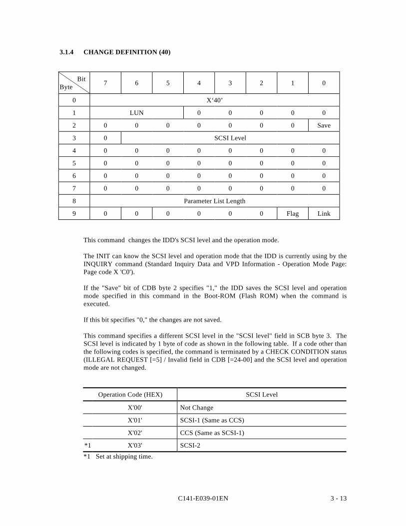
C141-E039-01EN 3 - 13
3.1.4 CHANGE DEFINITION (40)
BitByte 7 6 5 4 3 2 1 0
0 X‘40’
1 LUN 0 0 0 0 0
2 0 0 0 0 0 0 0 Save
3 0 SCSI Level
4 0 0 0 0 0 0 0 0
5 0 0 0 0 0 0 0 0
6 0 0 0 0 0 0 0 0
7 0 0 0 0 0 0 0 0
8 Parameter List Length
9 0 0 0 0 0 0 Flag Link
This command changes the IDD's SCSI level and the operation mode.
The INIT can know the SCSI level and operation mode that the IDD is currently using by theINQUIRY command (Standard Inquiry Data and VPD Information - Operation Mode Page:Page code X 'C0').
If the "Save" bit of CDB byte 2 specifies "1," the IDD saves the SCSI level and operationmode specified in this command in the Boot-ROM (Flash ROM) when the command isexecuted.
If this bit specifies "0," the changes are not saved.
This command specifies a different SCSI level in the "SCSI level" field in SCB byte 3. TheSCSI level is indicated by 1 byte of code as shown in the following table. If a code other thanthe following codes is specified, the command is terminated by a CHECK CONDITION status(ILLEGAL REQUEST [=5] / Invalid field in CDB [=24-00] and the SCSI level and operationmode are not changed.
Operation Code (HEX) SCSI Level
X'00' Not Change
X'01' SCSI-1 (Same as CCS)
X'02' CCS (Same as SCSI-1)
*1 X'03' SCSI-2
*1 Set at shipping time.
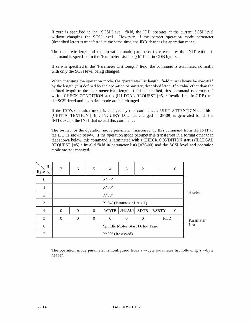
C141-E039-01EN3 - 14
If zero is specified in the "SCSI Level" field, the IDD operates at the current SCSI levelwithout changing the SCSI level. However, if the correct operation mode parameter(described later) is transferred at the same time, the IDD changes its operation mode.
The total byte length of the operation mode parameter transferred by the INIT with thiscommand is specified in the "Parameter List Length" field in CDB byte 8.
If zero is specified in the "Parameter List Length" field, the command is terminated normallywith only the SCSI level being changed.
When changing the operation mode, the "parameter list length" field must always be specifiedby the length (=8) defined by the operation parameter, described later. If a value other than thedefined length in the "parameter byte length" field is specified, this command is terminatedwith a CHECK CONDITION status (ILLEGAL REQUEST [=5] / Invalid field in CDB) andthe SCSI level and operation mode are not changed.
If the IDD's operation mode is changed by this command, a UNIT ATTENTION condition(UNIT ATTENTION [=6] / INQUIRY Data has changed [=3F-00] is generated for all theINITs except the INIT that issued this command.
The format for the operation mode parameter transferred by this command from the INIT tothe IDD is shown below. If the operation mode parameter is transferred in a format other thanthat shown below, this command is terminated with a CHECK CONDITION status (ILLEGALREQUEST [=5] / Invalid field in parameter list) [=26-00] and the SCSI level and operationmode are not changed.
BitByte 7 6 5 4 3 2 1 0
0 X‘00’
1 X‘00’
2 X‘00’
3 X‘04’ (Parameter Length)
4 0 0 0 WDTR UNTAIN SDTR RSRTY 0
5 0 0 0 0 0 0 RTD
6 Spindle Motor Start Delay Time
7 X‘00’ (Reserved)
The operation mode parameter is configured from a 4-byte parameter list following a 4-byteheader.
Header
ParameterList
C141-E039-01EN 3 - 15
(1) Header
a) Bytes 0 to 2
X '00' must be specified in this field.
b) Parameter Length
The parameter list length in byte 4 and subsequent bytes which follows the header must bespecified in this field. The parameter list length supported by the IDD is X '04' and theINIT must not specify a value other than X '04' in this field. If a value other than X '04' isspecified, this command is terminated with a CHECK CONDITION status (ILLEGALREQUEST [=5] / Invalid field in parameter list) [=26-00] and the operation mode are notchanged.
(2) Parameter List
a) WDTR (wide data transfer request: Effective for devices which support 16 bit SCSIonly.)This specifies whether or not a wide mode data transfer request from the IDD is permitted.
"1" (Permitted): After the power is switched on, after a RESET condition occurs or whenthe first command is received following reception of a BUS DEVICERESET message, if a WIDE DATA TRANSFER REQUEST (WDTR)message is not sent by the INIT, the IDD sends the WDTR message andattempts to establish wide mode data transfer.
"0"* (Prohibited):If it is necessary to establish wide mode data transfer, the IDD does notsend the WDTR message. However, if the INIT sends the WDTRmessage, the IDD responds normally.
* Set at shipping time
b) UNTATN (Unit Attention Report Mode)
This specifies the response method to commands received from the INIT when the IDD isholding a UNIT ATTENTION condition:
"1"* (Report): The IDD reports a CHECK CONDITION status (Standard SCSIspecification) in response to commands other than INQUIRY andREQUEST SENSE.
"0" (No Report): The IDD terminates all commands that are received normally. (ACHECK CONDITION status which causes a UNIT ATTENTIONcondition is not reported.)
* Set at shipping time
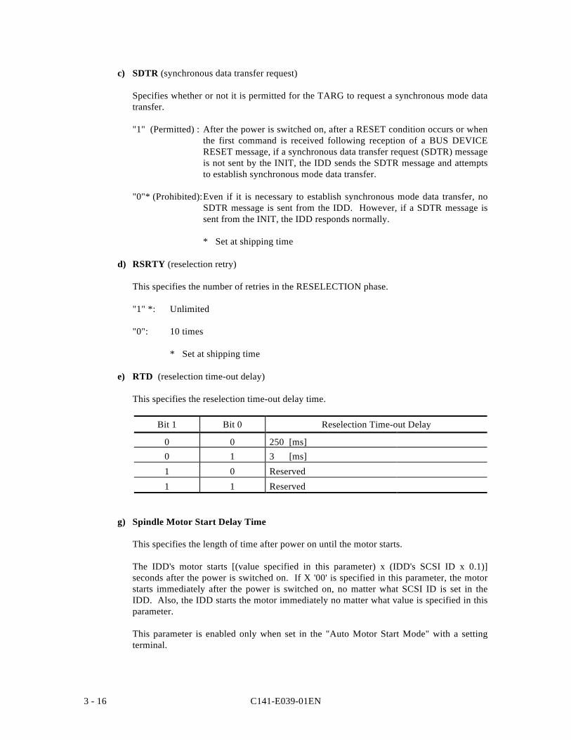
C141-E039-01EN3 - 16
c) SDTR (synchronous data transfer request)
Specifies whether or not it is permitted for the TARG to request a synchronous mode datatransfer.
"1" (Permitted) : After the power is switched on, after a RESET condition occurs or whenthe first command is received following reception of a BUS DEVICERESET message, if a synchronous data transfer request (SDTR) messageis not sent by the INIT, the IDD sends the SDTR message and attemptsto establish synchronous mode data transfer.
"0"* (Prohibited):Even if it is necessary to establish synchronous mode data transfer, noSDTR message is sent from the IDD. However, if a SDTR message issent from the INIT, the IDD responds normally.
* Set at shipping time
d) RSRTY (reselection retry)
This specifies the number of retries in the RESELECTION phase.
"1" *: Unlimited
"0": 10 times
* Set at shipping time
e) RTD (reselection time-out delay)
This specifies the reselection time-out delay time.
Bit 1 Bit 0 Reselection Time-out Delay
0 0 250 [ms]0 1 3 [ms]
1 0 Reserved
1 1 Reserved
g) Spindle Motor Start Delay Time
This specifies the length of time after power on until the motor starts.
The IDD's motor starts [(value specified in this parameter) x (IDD's SCSI ID x 0.1)]seconds after the power is switched on. If X '00' is specified in this parameter, the motorstarts immediately after the power is switched on, no matter what SCSI ID is set in theIDD. Also, the IDD starts the motor immediately no matter what value is specified in thisparameter.
This parameter is enabled only when set in the "Auto Motor Start Mode" with a settingterminal.
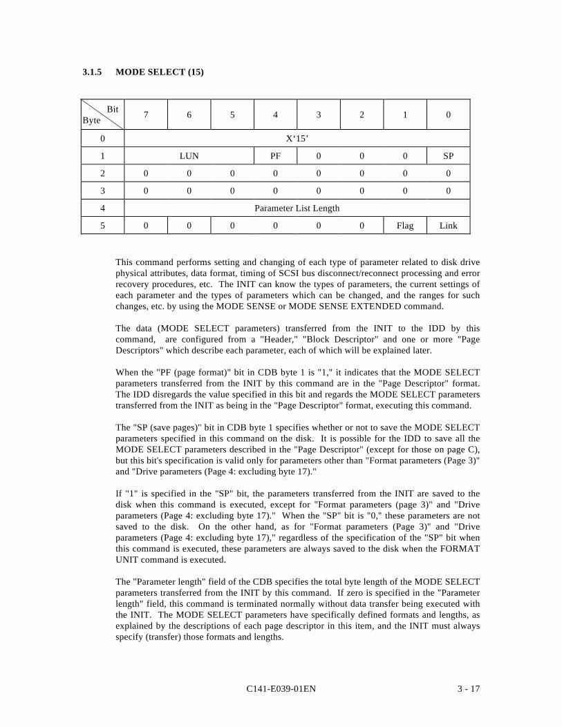
C141-E039-01EN 3 - 17
3.1.5 MODE SELECT (15)
BitByte 7 6 5 4 3 2 1 0
0 X‘15’
1 LUN PF 0 0 0 SP
2 0 0 0 0 0 0 0 0
3 0 0 0 0 0 0 0 0
4 Parameter List Length
5 0 0 0 0 0 0 Flag Link
This command performs setting and changing of each type of parameter related to disk drivephysical attributes, data format, timing of SCSI bus disconnect/reconnect processing and errorrecovery procedures, etc. The INIT can know the types of parameters, the current settings ofeach parameter and the types of parameters which can be changed, and the ranges for suchchanges, etc. by using the MODE SENSE or MODE SENSE EXTENDED command.
The data (MODE SELECT parameters) transferred from the INIT to the IDD by thiscommand, are configured from a "Header," "Block Descriptor" and one or more "PageDescriptors" which describe each parameter, each of which will be explained later.
When the "PF (page format)" bit in CDB byte 1 is "1," it indicates that the MODE SELECTparameters transferred from the INIT by this command are in the "Page Descriptor" format.The IDD disregards the value specified in this bit and regards the MODE SELECT parameterstransferred from the INIT as being in the "Page Descriptor" format, executing this command.
The "SP (save pages)" bit in CDB byte 1 specifies whether or not to save the MODE SELECTparameters specified in this command on the disk. It is possible for the IDD to save all theMODE SELECT parameters described in the "Page Descriptor" (except for those on page C),but this bit's specification is valid only for parameters other than "Format parameters (Page 3)"and "Drive parameters (Page 4: excluding byte 17)."
If "1" is specified in the "SP" bit, the parameters transferred from the INIT are saved to thedisk when this command is executed, except for "Format parameters (page 3)" and "Driveparameters (Page 4: excluding byte 17)." When the "SP" bit is "0," these parameters are notsaved to the disk. On the other hand, as for "Format parameters (Page 3)" and "Driveparameters (Page 4: excluding byte 17)," regardless of the specification of the "SP" bit whenthis command is executed, these parameters are always saved to the disk when the FORMATUNIT command is executed.
The "Parameter length" field of the CDB specifies the total byte length of the MODE SELECTparameters transferred from the INIT by this command. If zero is specified in the "Parameterlength" field, this command is terminated normally without data transfer being executed withthe INIT. The MODE SELECT parameters have specifically defined formats and lengths, asexplained by the descriptions of each page descriptor in this item, and the INIT must alwaysspecify (transfer) those formats and lengths.
C141-E039-01EN3 - 18
If a "Header," "Block Descriptor" or any "Page Descriptor" cannot be transferred with all thedefined length because the total defined length of the MODE SELECT parameters actuallytransferred from the INIT do not match the value specified in the "Parameter List Length"field, or if the total of the MODE SELECT parameter's defined length transferred from theINIT exceeds the value specified in the "Parameter list length" field, this command isterminated with a CHECK CONDITION status (ILLEGAL REQUEST [=5] / Invalid field inCDB) [=24-00], and all the MODE SELECT parameters transferred in the command aredisabled.
Three types of values exist in the MODE SELECT parameters, "Current," "Save" and"Default" values. "Current" values are parameters which actually control the IDD's operation,and the parameters specified by this command are converted to "Current" values. "Save"values are parameter values specified by this command which are preserved on the disk. And"Default" values are values which the IDD uses as "Current" values during the time untilreading of "Save" values is completed after the IDD's power is switched on, or when no"Save" values exist and no MODE SELECT command is being issued.
The IDD has a common set of "Current", "Save" and "Default" values of all the MODESELECT parameters for all the INITs.
When the IDD's power is switched on, when a RESET condition occurs or when the IDDreceives a BUS DEVICE RESET message, the "Current" MODE SELECT parameter valuesare changed to the "Save" parameter values, if they exist, and are changed to the "Default"parameter values if the "Save" values do not exist.
When any of the parameters related to the data format on the disk media (Block Descriptor,Format parameters: Page 3, and Drive parameters: Page 4), parameters related to the segmentbuffer (Caching parameters: Page 8, byte 13) and parameters related to command queuing(Control mode parameters: Page A, byte 3, D Que) is changed by this command, a UNITATTENTION condition (Mode parameters changed [=2A-01] is generated for all the INITsother than the INIT that issued this command.
When the RESERVE command is issued which specifies the Third Party Reserve function, the"Current" values of MODE SELECT parameters of the INIT that issued the RESERVEcommand are copied to "Current" values for a third party device specified by the RESERVEcommand. Details of this function are described in 3.1.11, "RESERVE (16)."
The relation between the three types of parameters, "Current," "Save" and "Default," is shownin the following diagram.
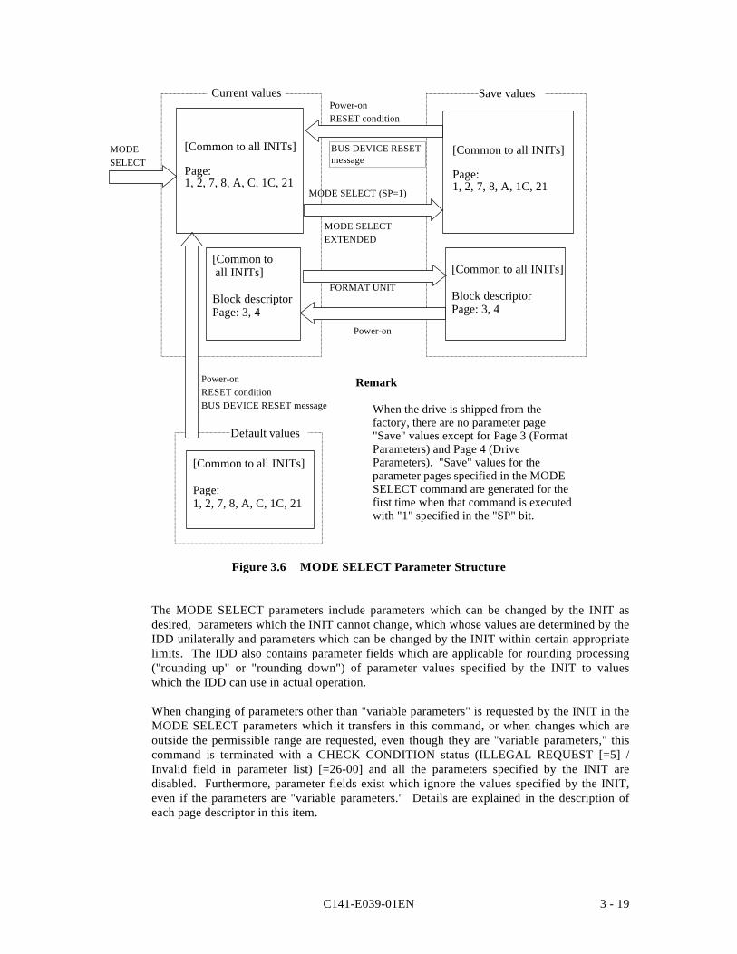
C141-E039-01EN 3 - 19
[Common to all INITs]
Block descriptorPage: 3, 4
[Common to all INITs]
Page:1, 2, 7, 8, A, C, 1C, 21
Power-onRESET conditionBUS DEVICE RESET message
Power-on
Remark
When the drive is shipped from thefactory, there are no parameter page"Save" values except for Page 3 (FormatParameters) and Page 4 (DriveParameters). "Save" values for theparameter pages specified in the MODESELECT command are generated for thefirst time when that command is executedwith "1" specified in the "SP" bit.
FORMAT UNIT
MODESELECT
MODE SELECTEXTENDED
MODE SELECT (SP=1)
Default values
[Common to all INITs]
Page:1, 2, 7, 8, A, C, 1C, 21
Save valuesCurrent values
[Common to all INITs]
Page:1, 2, 7, 8, A, 1C, 21
Power-onRESET condition
BUS DEVICE RESETmessage
[Common to all INITs]
Block descriptorPage: 3, 4
Figure 3.6 MODE SELECT Parameter Structure
The MODE SELECT parameters include parameters which can be changed by the INIT asdesired, parameters which the INIT cannot change, which whose values are determined by theIDD unilaterally and parameters which can be changed by the INIT within certain appropriatelimits. The IDD also contains parameter fields which are applicable for rounding processing("rounding up" or "rounding down") of parameter values specified by the INIT to valueswhich the IDD can use in actual operation.
When changing of parameters other than "variable parameters" is requested by the INIT in theMODE SELECT parameters which it transfers in this command, or when changes which areoutside the permissible range are requested, even though they are "variable parameters," thiscommand is terminated with a CHECK CONDITION status (ILLEGAL REQUEST [=5] /Invalid field in parameter list) [=26-00] and all the parameters specified by the INIT aredisabled. Furthermore, parameter fields exist which ignore the values specified by the INIT,even if the parameters are "variable parameters." Details are explained in the description ofeach page descriptor in this item.
C141-E039-01EN3 - 20
If the IDD performs rounding processing ("rounding up" or "rounding down") of parametervalues specified by the INIT, in some cases a "CHECK CONDITION" status (RECOVEREDERROR [=1] / Rounded parameter [37-00] is reported, and in some cases it is not reported.Whether or not a "CHECK CONDITION" status is reported is determined by the type of"rounding up" or "rounding down" and the conditions.
If the INIT would like to confirm that the IDD is implementing rounding processing, it issuesa MODE SENSE or MODE SENSE EXTENDED command after issuing this command andreads the values for the "Current" parameters, then compares them with the parameter valuessent in the MODE SELECT command.
Parameter fields which are the object of rounding processing are explained in the descriptionsof each page descriptor in this item.
Fig. 3.7 shows the data configuration of the parameter list transferred by the INIT in thiscommand. The parameter list is configured from header 4 bytes in length followed by a blockdescriptor with a length of 8 bytes. This is followed by one or more page descriptors, or,when there is no block descriptor the 4-byte header is followed by one or more pagedescriptors. The INIT may transfer a header only, or the header and block descriptor onlywithout the page descriptor added.
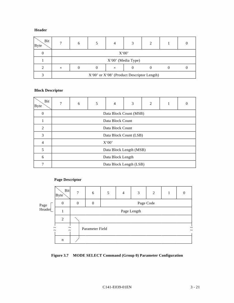
C141-E039-01EN 3 - 21
Header
BitByte 7 6 5 4 3 2 1 0
0 X‘00’
1 X‘00’ (Media Type)
2 × 0 0 × 0 0 0 0
3 X‘00’ or X‘08’ (Product Descriptor Length)
Block Descriptor
BitByte 7 6 5 4 3 2 1 0
0 Data Block Count (MSB)
1 Data Block Count
2 Data Block Count
3 Data Block Count (LSB)
4 X‘00’
5 Data Block Length (MSB)
6 Data Block Length
7 Data Block Length (LSB)
Page Descriptor
BitByte 7 6 5 4 3 2 1 0
0 0 0 Page Code
1 Page Length
2
n
Figure 3.7 MODE SELECT Command (Group 0) Parameter Configuration
~~
PageHeader
~~ ~~Parameter Field
C141-E039-01EN3 - 22
a. Header
• Media TypeX '00' (default type) must be specified in this field.
• Byte 2Byte 7 and byte 4 of this field have meaning only in the header transferred to the INITby the MODE SENSE and MODE SENSE EXTENDED commands. The valuesspecified in these bits are disregarded in the MODE SELECT and MODE SELECTEXTENDED commands. "0" must always be specified by the INIT in the other bitpositions.
• Block Descriptor LengthThis field indicates the length (block count) of the "Block descriptor" which followsthe header (not including the length of the "Page descriptor"). It is possible to defineonly 1 "Block descriptor" to the IDD, and either X '00' or X '08' must be specified inthis field. When X '00' is specified in this field, it indicates that the "Blockdescriptor" is not included in the parameter list transferred from the INIT and the"Page descriptor" follows immediately after the "Header."
b. Block Descriptor
The logical attributes of the data format on the disk media are described in the 8 byte long"Block descriptor."
Note:
The parameters in the "Block descriptor" are intimately related in the Formatparameters (Page 3) and the Drive parameters (Page 4). If the parameters in the"Block descriptor" are changed, the INIT should also specify the appropriate values inthe Format parameters (Page 3) and Drive parameters (Page 4) to correct them.
If only the "Block descriptor" in this command is changed, the IDD changes thevalues in the "Sector count/track," Data byte length/physical sector," "Track skewfactor" and "Cylinder skew factor," as well as the "Cylinder count" value in the driveparameters (Page 4) in accordance with the contents specified in the "Blockdescriptor," and uses the "Current" values as is for the other parameters.
C141-E039-01EN 3 - 23
• Data Block CountThis field specifies the total number of logical data blocks (the block length isspecified in "Data block length) allocated in the "User Space" on the disk media. Themaximum logical block address is a value with 1 subtracted from the value in thisfield.
The "Data block count" has an intimate relationship with the specifications on Pages 3and 4.
If only the "Block descriptor" in this command is changed, the "Cylinder count" onPage 4 is set to a realizable cylinder count which takes into account the "Alternatetrack count/drive" and "Alternate sector count/zone" components in Page 3 resultingfrom the value specified here (no rounding processing report is made). If this cylindercount exceeds the maximum cylinder count that can be use din the User Space, the"Data block count" is rounded to the maximum value that is realizable. (there is arounding processing report in this case).
If zero is specified for the "Data block count," or when the block descriptor is notspecified, the total number of blocks that it is possible to use after the "Alternate trackcount/drive" and "Alternate sector count/zone" components in Page 3 are subtractedfrom the "Cylinder count" on Page 4 is set in the "Data block count" (roundingprocessing is not reported).
• Data Block LengthThis field specifies the byte length of a logical data block on the disk media.
The logical data block length and physical data block length are the same in the IDD.The data block length can be specified at 512 to 528 bytes (2-byte boundary).
If less than 512 bytes is specified in this field, the IDD performs rounding processing(there is a rounding processing report), setting the data block length at 512 bytes. Ifmore than 528 bytes is specified, rounding processing is performed (there is arounding processing report), setting the data block length at 528 bytes. If an oddnumber is specified within this range, rounding processing is performed which adds+1 to the specified value (there is a rounding processing report).
If zero is specified in this field, the value specified in bytes 12 and 13 (Data bytelength/sector) of Page 3 (Format Parameter) is set. At that time, if Page 3 is notspecified at the same time, the current value in Page 3 is used.
If the value set in this field differs from the value specified in bytes 12 and 13 (Databyte length/sector) of Page 3 (Format Parameter), the data block length in the blockdescriptor is set.
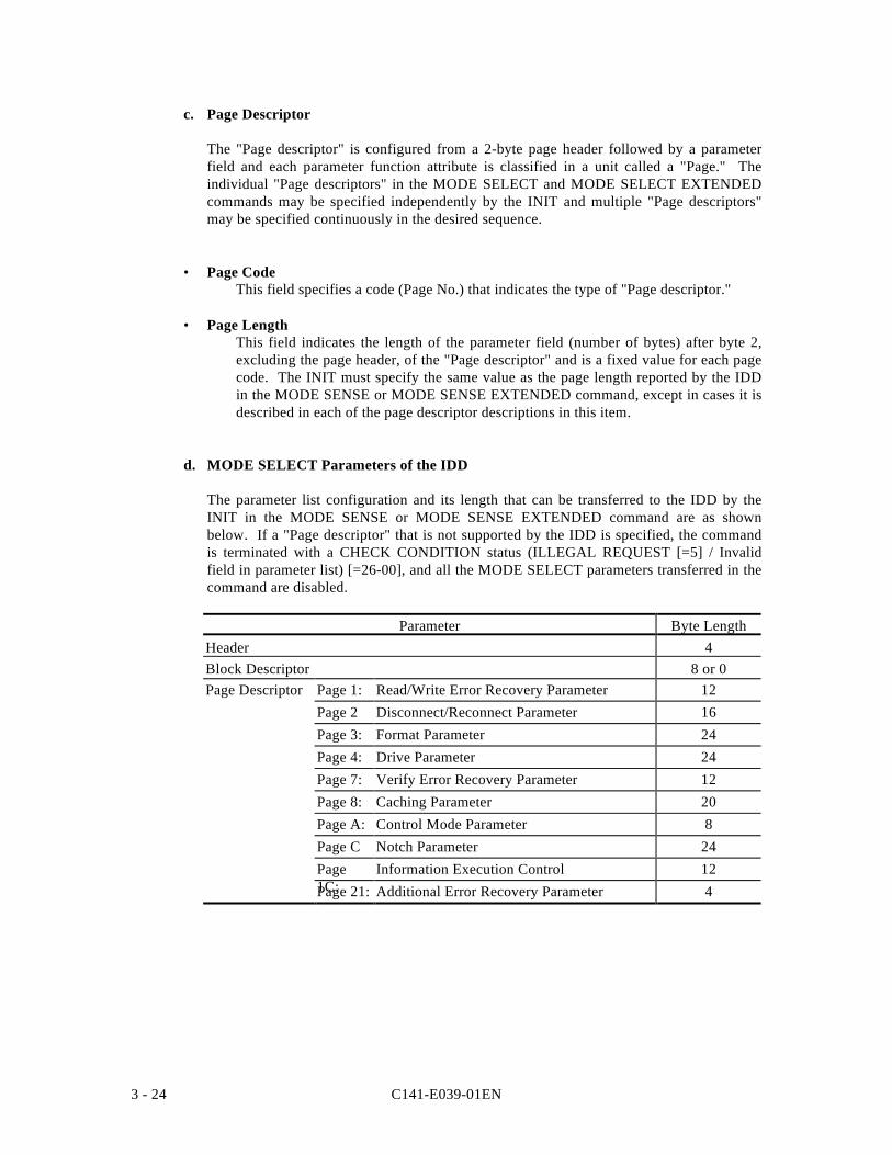
C141-E039-01EN3 - 24
c. Page Descriptor
The "Page descriptor" is configured from a 2-byte page header followed by a parameterfield and each parameter function attribute is classified in a unit called a "Page." Theindividual "Page descriptors" in the MODE SELECT and MODE SELECT EXTENDEDcommands may be specified independently by the INIT and multiple "Page descriptors"may be specified continuously in the desired sequence.
• Page CodeThis field specifies a code (Page No.) that indicates the type of "Page descriptor."
• Page LengthThis field indicates the length of the parameter field (number of bytes) after byte 2,excluding the page header, of the "Page descriptor" and is a fixed value for each pagecode. The INIT must specify the same value as the page length reported by the IDDin the MODE SENSE or MODE SENSE EXTENDED command, except in cases it isdescribed in each of the page descriptor descriptions in this item.
d. MODE SELECT Parameters of the IDD
The parameter list configuration and its length that can be transferred to the IDD by theINIT in the MODE SENSE or MODE SENSE EXTENDED command are as shownbelow. If a "Page descriptor" that is not supported by the IDD is specified, the commandis terminated with a CHECK CONDITION status (ILLEGAL REQUEST [=5] / Invalidfield in parameter list) [=26-00], and all the MODE SELECT parameters transferred in thecommand are disabled.
Parameter Byte LengthHeader 4Block Descriptor 8 or 0Page Descriptor Page 1: Read/Write Error Recovery Parameter 12
Page 2 Disconnect/Reconnect Parameter 16Page 3: Format Parameter 24Page 4: Drive Parameter 24Page 7: Verify Error Recovery Parameter 12Page 8: Caching Parameter 20Page A: Control Mode Parameter 8Page C Notch Parameter 24Page1C:
Information Execution Control 12Page 21: Additional Error Recovery Parameter 4
C141-E039-01EN 3 - 25
Notes:
1. The MODE SELECT parameter is ordinarily different in its configuration dependingon the input/output device and the type of controller. It is also possible that currentdefinitions may be expanded in accordance with the expansion of the functions of theIDD in the future. In order to assure independence of software from the individualspecifications of input/output devices, before the INIT issues this command, it shouldfollow the procedure of using the MODE SENSE and MODE SENSE EXTENDEDcommand to determine the types of parameters the TARG is actually equipped withand the attributes of those parameters, such as whether or not they can be changed.
2. After changing anything in the "Block descriptor," "Format parameters (Page 3)" or"Drive parameters (Page 4)," with the MODE SELECT or MODE SELECTEXTENDED command, it is impossible to execute a command to access the data onthe disk media until execution of the FORMAT UNIT command is completed, and aCHECK CONDITION status (MEDIUM ERROR [=3] / Medium format corrupted[=31-00] is reported for all such commands.
The configuration and functions of the "Page descriptors" supported by the IDD are describedbelow.
Note:
In the diagram that shows the configuration of each individual "Page Descriptor," thedefault column shows that parameter's "default" value and the "variable" column showswhether or not it is possible to vary that parameter ("1" indicates that it can be varied).The INIT can know those values and attributes by using the MODE SENSE or MODESENSE EXTENDED command.
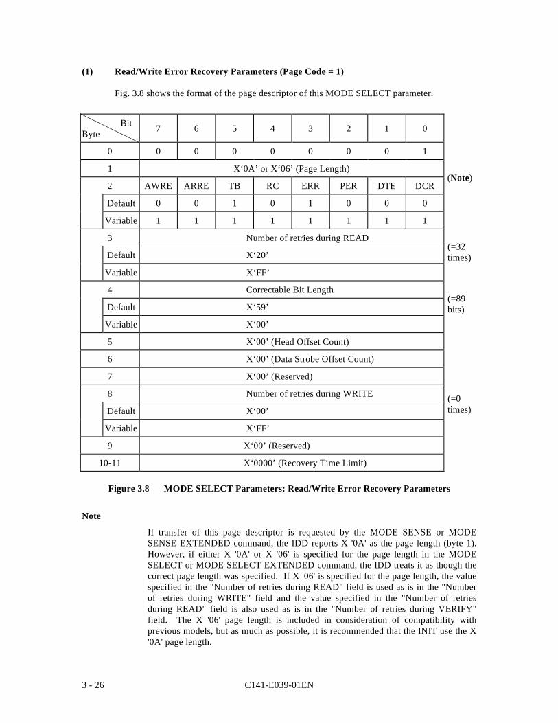
C141-E039-01EN3 - 26
(1) Read/Write Error Recovery Parameters (Page Code = 1)
Fig. 3.8 shows the format of the page descriptor of this MODE SELECT parameter.
BitByte 7 6 5 4 3 2 1 0
0 0 0 0 0 0 0 0 1
1 X‘0A’ or X‘06’ (Page Length)
2 AWRE ARRE TB RC ERR PER DTE DCR
Default 0 0 1 0 1 0 0 0
Variable 1 1 1 1 1 1 1 1
3 Number of retries during READ
Default X‘20’
Variable X‘FF’
4 Correctable Bit Length
Default X‘59’
Variable X‘00’
5 X‘00’ (Head Offset Count)
6 X‘00’ (Data Strobe Offset Count)
7 X‘00’ (Reserved)
8 Number of retries during WRITE
Default X‘00’
Variable X‘FF’
9 X‘00’ (Reserved)
10-11 X‘0000’ (Recovery Time Limit)
Figure 3.8 MODE SELECT Parameters: Read/Write Error Recovery Parameters
Note
If transfer of this page descriptor is requested by the MODE SENSE or MODESENSE EXTENDED command, the IDD reports X '0A' as the page length (byte 1).However, if either X '0A' or X '06' is specified for the page length in the MODESELECT or MODE SELECT EXTENDED command, the IDD treats it as though thecorrect page length was specified. If X '06' is specified for the page length, the valuespecified in the "Number of retries during READ" field is used as is in the "Numberof retries during WRITE" field and the value specified in the "Number of retriesduring READ" field is also used as is in the "Number of retries during VERIFY"field. The X '06' page length is included in consideration of compatibility withprevious models, but as much as possible, it is recommended that the INIT use the X'0A' page length.
(=89bits)
(=0times)
(=32times)
(Note)
C141-E039-01EN 3 - 27
Error recovery parameters defined in this page descriptor are applicable for the followingcommands, except in cases where it is specifically pointed out.
• READ • WRITE
• READ EXTENDED • WRITE AND VERIFY (Write operation)
• READ LONG • WRITE EXTENDED
• SEND DIAGNOSTIC (Write/read test) • WRITE LONG
a. AWRE (automatic write reallocation enabled)
"1" : An "automatic alternate block allocation processing" operation is specified duringexecution of a write operation.
"0" : An "automatic alternate block allocation processing" operation is prohibited duringexecution of a write operation.
The IDD does not support automatic alternate processing during a write operation. the IDDdisregards the specification of this bit and operates according to the default value, (=0).
b. ARRE (automatic read reallocation enable)
"1" : An "automatic alternate block allocation processing" operation is specified duringexecution of a read operation.
"0" : An "automatic alternate block allocation processing" operation is prohibited duringexecution of a read operation.
Automatic alternate block allocation processing is explained in item 4.3.2.
c. TB (transfer block)
"1" : Data blocks which contain errors that are impossible to correct are transferred to theINIT during a read operation.
"0" : Data blocks which contain errors that are impossible to correct are not transferred tothe INIT during a read operation.
d. RC (Read Continuous)
This bit specifies continuous transfer of all the data requested by a commandunaccompanied by a delay for executing error recovery processing.
The IDD disregards the specification in this bit and operates according to the default value,(=0).
C141-E039-01EN3 - 28
e. EER (enable early recovery)
"1" : When a correctable data check has been detected, data correction according to theECC is applied immediately without executing retry (rereading) up to the number oftimes specified in the "Number of retries during READ" parameter.
"0" : When a correctable data check has been detected, retry (rereading) is executed up tothe number of times specified in the "Number of retries during READ" parameter,then data correction according to the ECC is applied if possible.
The IDD disregards this bit and operates according to the default value, (=1).
f. PER (post error)
"1" : When several errors (errors related to the disk drive), which were recovered fromnormally through the IDD's error recovery processing, have been detected, aCHECK CONDITION status is reported when execution of that command iscompleted. In the sense data generated at this time, the sense key indicates"RECOVERED ERROR [=1]" and the content of the final error to be correctedsuccessfully is reported.
"0" : Even when several errors (errors related to the disk drive), which were recoveredfrom normally through the IDD's error recovery processing, have been detected, thatcommand is completed with a GOOD status and the contents of the recovered errorsare not reported.
g. DTE (disable transfer on error)
"1" : Even when several errors on the disk drive, which were recovered from normallythrough the IDD's error recovery processing, have been detected, execution of thatcommand terminates at that point.
"0" : When several errors on the disk drive, which were recovered from normally throughthe IDD's error recovery processing, have been detected, execution of that commandis continued.
The IDD disregards this bit and operates according to the default value, (=0).
h. DCR (disable correction)
"1" : Even when a correctable data check has been detected, data correction according tothe ECC is prohibited. However, On-the-fly correction processing is not prohibited.
"0" : When a correctable data check has been detected, data correction according to theECC is applied.
The IDD disregards this bit and operates according to the default value (=0).
C141-E039-01EN 3 - 29
i. Number of Retries during READ
This parameter specifies the number of retries that should be executed for "Data Check"type errors detected in read operations on the disk media. The number of retries specifiedin this parameter is the maximum number of times reading is retried for each individualportion of data in each logical data block. If the IDD cannot perform correction of the dataOn-the-fly for each portion of data in the data block, it retries the reading of those portions.The reread retry is executed the number of times specified by the drive parameterinternally by the IDD before this retry is executed, so actually the retry is executed thenumber specified here plus the number of internal retries.
The value specified in this parameter is applicable to the READ/READ EXTENDEDcommands and the read test in the SEND DIAGNOSTIC command.
When the page length in Page 1 is specified as X '06,' the value specified in this field iscopied to the "Number of retries during WRITE" on this page and "Number of retriesduring VERIFY" on Page 7.
j. Correctable Bit Length
This parameter indicates the burst error length (bit length) which it is possible to applydata correction according to the ECC to. It is impossible to change this parameter from theINIT. The IDD disregards the value specified in this parameter and operates according tothe "Default" value.
k. Number of Retries during WRITE
This field specifies the maximum number of times writing of data to the disk media isretried in the case that there has been an interruption in a write operation such as animpact. the number of retries specified in this field is applied to each logical block unit.When zero is specified in this field, retrying of writing to the disk is prohibited.
The value specified in this field is applicable to the WRITE command, WRITEEXTENDED command, write operations in the WRITE AND VERIFY command andwrite tests in the SEND DIAGNOSTIC command. When the page length in Page 1 isspecified as X '06,' the value specified in this field is not transferred from the INIT, but inthis case, the value specified in the "Number of retries during READ," on the same Page,is also applied to this field by the IDD.
C141-E039-01EN3 - 30
l. Recovery Time Limit
This parameter specifies the maximum time that can be used by the TARG for errorrecovery processing, as a 1 (s constant. The value specified in this parameter is themaximum permissible time for error recovery processing for each individual logical datablock. When both this parameter and the "Number of retries" parameter are specified, theparameter which specifies the shortest time must be given priority in application.
The IDD does not support this parameter. The IDD disregards the value specified in thisparameter.
Table 3.1 Combination of Error Recovery Flags (1/3)
EER PER DTE DCR Error Recovery Procedure
0 0 0 0 1. Rereading is tried repeatedly up to the number of times specified in the "ReadRetry Count", "Write Retry Count" or "Verify Retry Count" parameter. Ifpossible, data correction is executed afterward according to the ECC.
2. When error recovery has succeeded, processing of the command is continued
3. The contents of recovered errors are not reported.
4. If unrecoverable errors have been detected, execution of that command isterminated at that point.
5. Transfer of data in blocks which include unrecoverable errors to the INIT isdone in accordance with the specification in the TB bit (Read systemcommand).
0 0 0 1 1. Rereading is tried repeatedly up to the number of times specified in the "ReadRetry Count", "Write Retry Count" or "Verify Retry Count" parameter. Datacorrection is not executed according to the ECC.
2. When error recovery has succeeded, processing of the command is continued.
3. The contents of recovered errors are not reported.
4. If unrecoverable errors have been detected, execution of that command isterminated at that point.
5. Transfer of data in blocks which include unrecoverable errors to the INIT isdone in accordance with the specification in the TB bit (Read systemcommand).
0 0 1 0 (Setting prohibited) (See *1 at the end of this table.)
0 0 1 1 (Setting prohibited) (See *1 at the end of this table.)
0 1 0 0 1. Rereading is tried repeatedly up to the number of times specified in the "ReadRetry Count", "Write Retry Count" or "Verify Retry Count" parameter. Ifpossible, data correction is executed afterward according to the ECC.
2. When error recovery has succeeded, processing of the command is continued.
3. If unrecoverable errors have been detected, execution of that command isterminated at that point.
4. Transfer of data in blocks which include unrecoverable errors to the INIT isdone in accordance with the specification in the TB bit (Read systemcommand).
5. When recovery from all detected errors has been successful, a CHECKCONDITION status (RECOVERED ERROR [=1] is reported after allprocessing of the command is completed and the sense data indicate thecontent of the last error that was successfully recovered from and the addressof the data block where that error occurred.
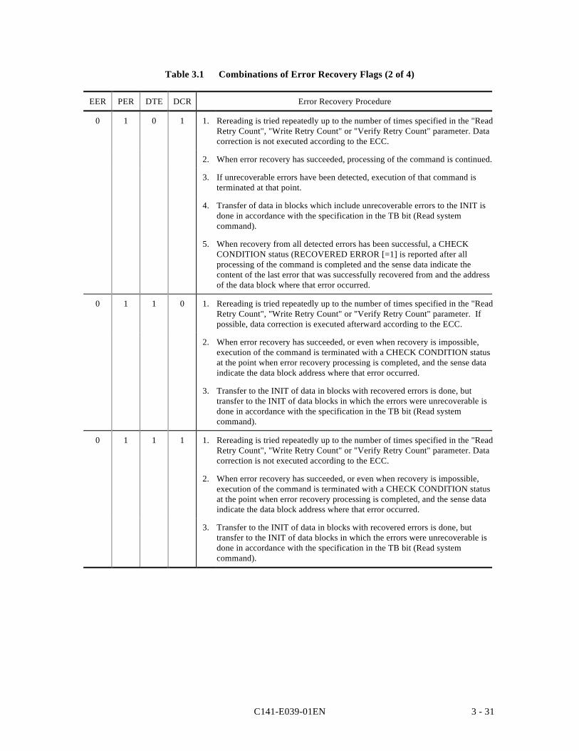
C141-E039-01EN 3 - 31
Table 3.1 Combinations of Error Recovery Flags (2 of 4)
EER PER DTE DCR Error Recovery Procedure
0 1 0 1 1. Rereading is tried repeatedly up to the number of times specified in the "ReadRetry Count", "Write Retry Count" or "Verify Retry Count" parameter. Datacorrection is not executed according to the ECC.
2. When error recovery has succeeded, processing of the command is continued.
3. If unrecoverable errors have been detected, execution of that command isterminated at that point.
4. Transfer of data in blocks which include unrecoverable errors to the INIT isdone in accordance with the specification in the TB bit (Read systemcommand).
5. When recovery from all detected errors has been successful, a CHECKCONDITION status (RECOVERED ERROR [=1] is reported after allprocessing of the command is completed and the sense data indicate thecontent of the last error that was successfully recovered from and the addressof the data block where that error occurred.
0 1 1 0 1. Rereading is tried repeatedly up to the number of times specified in the "ReadRetry Count", "Write Retry Count" or "Verify Retry Count" parameter. Ifpossible, data correction is executed afterward according to the ECC.
2. When error recovery has succeeded, or even when recovery is impossible,execution of the command is terminated with a CHECK CONDITION statusat the point when error recovery processing is completed, and the sense dataindicate the data block address where that error occurred.
3. Transfer to the INIT of data in blocks with recovered errors is done, buttransfer to the INIT of data blocks in which the errors were unrecoverable isdone in accordance with the specification in the TB bit (Read systemcommand).
0 1 1 1 1. Rereading is tried repeatedly up to the number of times specified in the "ReadRetry Count", "Write Retry Count" or "Verify Retry Count" parameter. Datacorrection is not executed according to the ECC.
2. When error recovery has succeeded, or even when recovery is impossible,execution of the command is terminated with a CHECK CONDITION statusat the point when error recovery processing is completed, and the sense dataindicate the data block address where that error occurred.
3. Transfer to the INIT of data in blocks with recovered errors is done, buttransfer to the INIT of data blocks in which the errors were unrecoverable isdone in accordance with the specification in the TB bit (Read systemcommand).
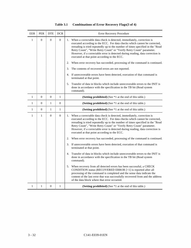
C141-E039-01EN3 - 32
Table 3.1 Combinations of Error Recovery Flags(3 of 4)
EER PER DTE DCR Error Recovery Procedure
1 0 0 0 1. When a correctable data check is detected, immediately, correction isexecuted according to the ECC. For data checks which cannot be corrected,rereading is tried repeatedly up to the number of times specified in the "ReadRetry Count", "Write Retry Count" or "Verify Retry Count" parameter.However, if a correctable error is detected during reading, data correction isexecuted at that point according to the ECC.
2. When error recovery has succeeded, processing of the command is continued.
3. The contents of recovered errors are not reported.
4. If unrecoverable errors have been detected, execution of that command isterminated at that point.
5. Transfer of data in blocks which include unrecoverable errors to the INIT isdone in accordance with the specification in the TB bit (Read systemcommand).
1 0 0 1 (Setting prohibited) (See *1 at the end of this table.)
1 0 1 0 (Setting prohibited) (See *1 at the end of this table.)
1 0 1 1 (Setting prohibited) (See *1 at the end of this table.)
1 1 0 0 1. When a correctable data check is detected, immediately, correction isexecuted according to the ECC. For data checks which cannot be corrected,rereading is tried repeatedly up to the number of times specified in the "ReadRetry Count", "Write Retry Count" or "Verify Retry Count" parameter.However, if a correctable error is detected during reading, data correction isexecuted at that point according to the ECC.
2. When error recovery has succeeded, processing of the command is continued.
3. If unrecoverable errors have been detected, execution of that command isterminated at that point.
4. Transfer of data in blocks which include unrecoverable errors to the INIT isdone in accordance with the specification in the TB bit (Read systemcommand).
5. When recovery from all detected errors has been successful, a CHECKCONDITION status (RECOVERED ERROR [=1] is reported after allprocessing of the command is completed and the sense data indicate thecontent of the last error that was successfully recovered from and the addressof the data block where that error occurred.
1 1 0 1 (Setting prohibited) (See *1 at the end of this table.)
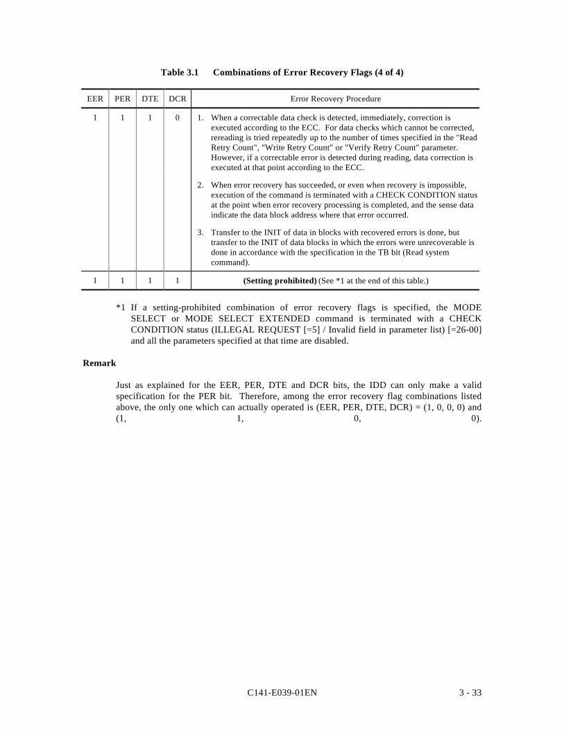
C141-E039-01EN 3 - 33
Table 3.1 Combinations of Error Recovery Flags (4 of 4)
EER PER DTE DCR Error Recovery Procedure
1 1 1 0 1. When a correctable data check is detected, immediately, correction isexecuted according to the ECC. For data checks which cannot be corrected,rereading is tried repeatedly up to the number of times specified in the "ReadRetry Count", "Write Retry Count" or "Verify Retry Count" parameter.However, if a correctable error is detected during reading, data correction isexecuted at that point according to the ECC.
2. When error recovery has succeeded, or even when recovery is impossible,execution of the command is terminated with a CHECK CONDITION statusat the point when error recovery processing is completed, and the sense dataindicate the data block address where that error occurred.
3. Transfer to the INIT of data in blocks with recovered errors is done, buttransfer to the INIT of data blocks in which the errors were unrecoverable isdone in accordance with the specification in the TB bit (Read systemcommand).
1 1 1 1 (Setting prohibited) (See *1 at the end of this table.)
*1 If a setting-prohibited combination of error recovery flags is specified, the MODESELECT or MODE SELECT EXTENDED command is terminated with a CHECKCONDITION status (ILLEGAL REQUEST [=5] / Invalid field in parameter list) [=26-00]and all the parameters specified at that time are disabled.
Remark
Just as explained for the EER, PER, DTE and DCR bits, the IDD can only make a validspecification for the PER bit. Therefore, among the error recovery flag combinations listedabove, the only one which can actually operated is (EER, PER, DTE, DCR) = (1, 0, 0, 0) and(1, 1, 0, 0).
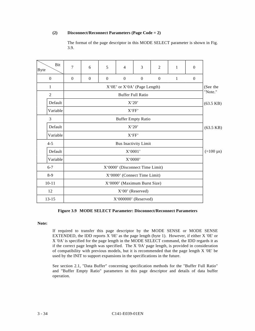
C141-E039-01EN3 - 34
(2) Disconnect/Reconnect Parameters (Page Code = 2)
The format of the page descriptor in this MODE SELECT parameter is shown in Fig.3.9.
BitByte 7 6 5 4 3 2 1 0
0 0 0 0 0 0 0 1 0
1 X‘0E’ or X‘0A’ (Page Length)
2 Buffer Full Ratio
Default X‘20’
Variable X‘FF’
3 Buffer Empty Ratio
Default X‘20’
Variable X‘FF’
4-5 Bus Inactivity Limit
Default X‘0001’
Variable X‘0000’
6-7 X‘0000’ (Disconnect Time Limit)
8-9 X‘0000’ (Connect Time Limit)
10-11 X‘0000’ (Maximum Burst Size)
12 X‘00’ (Reserved)
13-15 X‘000000’ (Reserved)
Figure 3.9 MODE SELECT Parameter: Disconnect/Reconnect Parameters
Note:
If required to transfer this page descriptor by the MODE SENSE or MODE SENSEEXTENDED, the IDD reports X '0E' as the page length (byte 1). However, if either X '0E' orX '0A' is specified for the page length in the MODE SELECT command, the IDD regards it asif the correct page length was specified. The X '0A' page length, is provided in considerationof compatibility with previous models, but it is recommended that the page length X '0E' beused by the INIT to support expansions in the specifications in the future.
See section 2.1, "Data Buffer" concerning specification methods for the "Buffer Full Ratio"and "Buffer Empty Ratio" parameters in this page descriptor and details of data bufferoperation.
(See the"Note.")(63.5 KB)
(63.5 KB)
(=100 µs)
C141-E039-01EN 3 - 35
a. Buffer Full Ratio
This parameter specifies the timing for the IDD to start reconnection processing in order totransfer data to the INIT by the READ or READ EXTENDED command.
The value specified in this parameter (n) shows the amount of data read to the IDD's databuffer from the disk media as a proportion [n/256] of the total capacity of the data bufferuntil reconnection processing with the SCSI bus is started. The IDD's default segmentcapacity is 127 Kbytes. Therefore, if the specified value (n) is 128, for example, it meansthat a data volume of 63.5 Kbytes was specified (Note)
If it is possible to transfer the amount of data specified in this parameter to the INIT fromthe data buffer, reconnection processing is executed and transfer of data to the INITbegins.
The default value for this parameter is X '20.' It is possible to specify X '00' in thisparameter, but the minimum effective value of the buffer full ratio is 1 logical data block,so specifying X '00' is equivalent to specifying the value for 1 logical data block. (Note)
b. Buffer Empty Ratio
This parameter specifies the timing for the IDD to start reconnection when it is requestedby the INIT to transfer data in the WRITE, WRITE EXTENDED or WRITE ANDVERIFY command.
The value specified in this parameter (n) indicates the size of the empty area in the IDD'sdata buffer as a proportion of the total data buffer capacity of the IDD [n/256]. Forexample, if the specified value (n) is 128 and the number of cache segments is 4 (this is thedefault value), the size of the empty space in the buffer is specified as 63.5 Kbytes. (Note)
While the IDD is writing data to the disk media, it is using the data pre-fetched to the databuffer in order, and when the empty space in the data buffer reaches the amount specifiedin this parameter, it executes reconnection processing, requesting transfer of thesucceeding data.
If the total number of bytes in the transferred data block count specified in the command isless than the capacity of the buffer segment, all the data are pre-fetched in a batch, so thespecification in this parameter is not applied.
Note:
If the value specified for the "buffer full ratio" or the "buffer empty ratio" is notwithin double the integral boundary of the logical data block length, the IDD roundsup the specified value to the value which is the nearest data block boundary. Also, ifzero is specified in any of these parameters, the IDD treats that parameter as though 1logical data block has been specified. However, parameter values specified from theINIT in the MODE SELECT or MODE SELECT EXTENDED command are held asis and those values are reported in response to a MODE SENSE or MODE SENSEEXTENDED command. (Rounding processing of the parameters is not done by theIDD.) Also, if the specified value does not reach 1 block, it is regarded as havingspecified 1 block.
C141-E039-01EN3 - 36
c. Bus Inactivity Limit
This parameter indicates the maximum time that the TARG is permitted to keep the SCSIbus in the Busy state (BSY Signal = TRUE) without executing a REQ/ACK handshake, inmultiples of 100 µs. In the IDD, this value is 100 µs during normal operation. It isimpossible for this parameter to be changed by the INIT. The IDD disregards the valuespecified in this parameter and operates according to the "Default" value.
d. Disconnect Time Limit
This parameter specifies the maximum time that the TARG is permitted to continue in thedisconnect state until it starts reconnect processing, in multiples of 100 µs.
In the IDD, this value is 0 µs. It is impossible for this parameter to be changed by theINIT. The IDD disregards the value specified in this parameter and operates according tothe "Default" value.
e Connect Time Limit
This parameter specifies the maximum time that the TARG is permitted to use the SCSIbus until it starts disconnect processing, in multiples of 100 µs.
In the IDD, this value is 0(s. It is impossible for this parameter to be changed by the INIT.The IDD disregards the value specified in this parameter and operates according to the"Default" value..
f. Maximum Burst Size
This parameter specifies the maximum volume of data the TARG is permitted to transfercontinuously in the DATA IN phase or the DATA OUT phase until it starts disconnectprocessing, in multiples of 512 bytes.
In the IDD, this value is 0(s. It is impossible for this parameter to be changed by the INIT.The IDD disregards the value specified in this parameter and operates according to the"Default" value.
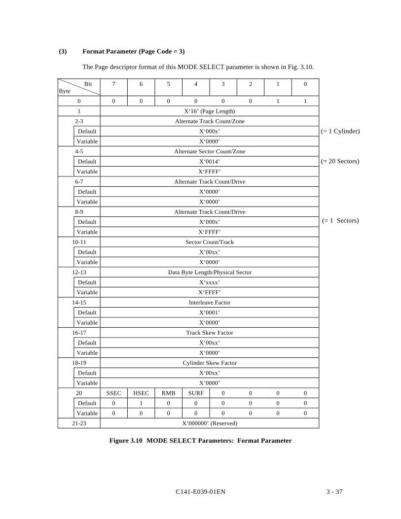
C141-E039-01EN 3 - 37
(3) Format Parameter (Page Code = 3)
The Page descriptor format of this MODE SELECT parameter is shown in Fig. 3.10.
BitByte
7 6 5 4 3 2 1 0
0 0 0 0 0 0 0 1 1
1 X‘16’ (Page Length)
2-3 Alternate Track Count/Zone
Default X‘000x’
Variable X‘0000’
4-5 Alternate Sector Count/Zone
Default X‘0014’
Variable X‘FFFF’
6-7 Alternate Track Count/Drive
Default X‘0000’
Variable X‘0000’
8-9 Alternate Track Count/Drive
Default X‘000x’
Variable X‘FFFF’
10-11 Sector Count/Track
Default X‘00xx’
Variable X‘0000’
12-13 Data Byte Length/Physical Sector
Default X‘xxxx’
Variable X‘FFFF’
14-15 Interleave Factor
Default X‘0001’
Variable X‘0000’
16-17 Track Skew Factor
Default X‘00xx’
Variable X‘0000’
18-19 Cylinder Skew Factor
Default X‘00xx’
Variable X‘0000’
20 SSEC HSEC RMB SURF 0 0 0 0
Default 0 1 0 0 0 0 0 0
Variable 0 0 0 0 0 0 0 0
21-23 X‘000000’ (Reserved)
Figure 3.10 MODE SELECT Parameters: Format Parameter
(= 20 Sectors)
(= 1 Cylinder)
(= 1 Sectors)
C141-E039-01EN3 - 38
a. Parameters for Specifying Alternate Processing Areas for Defective Blocks (Bytes 2 to 9)
The following 4 parameters specify the position and number of spare sectors forperforming defective block alternate allocation processing on the disk media. See Chapter3, "Data Format" of "OEM Manual VOL. 1, Product Specifications/InstallationProcedures" for details of the IDD's alternate block processing.
• Track Count/ZoneThis parameter specifies spare sectors in assigned units (zone, b, c) for alternatingblocks. The INIT cannot clearly specify this value. The IDD ignores the specificationfor this bit. The “Number of Logic Heads” is output by the MODE SENSE andMODE SENSE EXTENDED commands.
When the notch is active (refer ‘notch parameter’ on page c), the “Total Number of Tracks”of the specified zone (No. of ceilings in the zone x No. of logic heads) is reported.
• Alternate Sector Count/ZoneThis parameter specifies the number of sectors per one zone as the number of spare sectorssecured for use as alternate blocks. In the IDD, this parameter indicates the number ofspare sectors secured in each cylinder. The maximum permissible value of this parametereither the "number of physical sectors per track in the final zone - 1" or "32", whichever issmaller. It is possible for the INIT to vary this parameter within a range of 0 to themaximum permissible value. When a value which exceeds the maximum permissiblevalue is specified, the IDD performs rounding down of the parameter and sets a value equalto this parameter's maximum permissible value. If the above rounding processing isperformed, a CHECK CONDITION status (RECOVERED ERROR {= 1} / Roundedparameter [37-00] is reported for that command.
• Alternate Track Count / ZoneThis parameter specifies the area secured for alternate blocks as the number of tracksper one zone. It is impossible to change this parameter. When a value other than zerois specified in this field, the IDD performs rounding down processing of thisparameter and always sets this parameter value at zero.
• Alternate Track Count / DriveThis parameter specifies the area secured for alternate blocks as the number of tracksper disk drive.
In the IDD, this parameter indicates the number of tracks in the spare area secured asalternate cylinders. This value is fixed at the number of tracks per 1 cylinder in theIDD and this parameter cannot be changed from the INIT.
b. Parameters which Specify the Track Format (Bytes 10, 11)
• Sector Count/TrackThis parameter specifies the number of physical sectors per 1 track. In the IDD, thenumber of physical sectors in a track is set unilaterally according to the data formatspecified by the "Data Block Length" parameter in the block descriptor or the "Databyte length/Physical sector" parameter in this page descriptor, so this parametercannot be changed. The IDD disregards the value specified in this field. Thisparameter always indicates the value of zone 0. Also, the "default" value of thisparameter indicates a value which matches the current data format.
C141-E039-01EN 3 - 39
c. Parameters which Specify the Sector Format (Bytes 12 to 19)
• Data Byte Length/Physical SectorsThis parameter specifies the data length per 1 physical sector as the number of bytes.In the IDD, the data byte length per 1 physical sector is the same as the data bytelength in 1 logical data block. The INIT can specify the value of this parameter at 0or 512 to 528 bytes (2-byte boundary).
If a value less than 512 bytes, the IDD sets a byte length of 512. If more than 528bytes is specified, the IDD performs rounding processing and sets a byte length of528. If an odd number of bytes is specified within the specified range, the IDDperforms rounding up processing. If the above rounding processing is performed, theIDD reports the CHECK CONDITION status (RECOVERED ERROR [=1] / Roundedparameter [37-00] for that command.
If 0 is specified in this parameter, the value calculated based on the value of the "Datablock length" in the block descriptor is used as this parameter value.
When both this page descriptor and the block descriptor are specified by the sameMODE SELECT command, and a nonzero value is specified in this parameter whichdiffers from the value in the "Data block length" parameter in the block descriptor, thevalue specified in the block descriptor has priority.
• Interleave FactorThis parameter field has meaning only with the MODE SENSE and MODE SENSEEXTENDED commands. The interleave factor (in the IDD, this is always X '0001':non interleave) of the disk drive's current data format. The value specified in thisfield is disregarded in the MODE SELECT and MODE SELECT EXTENDEDcommands.
• Track Skew FactorThis parameter indicates the number of physical sectors existing between the datablock with the highest order logical block address on a track and the data block withthe next logical block address on the next track of the same cylinder (track skew).This parameter cannot be changed. The IDD disregards the value specified in thisfield and sets the optimum track skew value in the specified data block length. SeeChapter 3, "Data Format" in the "OEM Manual, Product Specifications/InstallationProcedure" for details about track skew. This parameter always indicates the value inzone 0. Also, the "Default" value of this parameter indicates a value which matchesthe current data format.
• Cylinder Skew FactorThis parameter indicates the number of physical sectors existing between the datablock with the highest order logical block address in a cylinder and the data blockwith the next logical block address in the next cylinder (cylinder skew). Thisparameter cannot be changed. The IDD disregards the value specified in this field andsets the optimum cylinder skew value in the specified data block length. See Chapter3, "Data Format" in the "OEM Manual, Product Specifications/InstallationProcedure" for details about cylinder skew. This parameter always indicates the valuein zone 0. Also, the "Default" value of this parameter indicates a value whichmatches the current data format.
C141-E039-01EN3 - 40
d. Parameters Related to Device Type (Byte 20)
• SSEC (soft sectoring)When this bit is "1," it indicates that the data formatting method on the disk media is"soft sectoring." However, since the IDD uses only the "hard sectoring" method(refer to previously shown item b), this bit is disregarded. Furthermore, it isimpossible to change this parameter.
• HSEC (hard sectoring)When this bit is "1," it indicates that the data formatting method on the disk media is"hard sectoring." However, since the IDD uses only the "hard sectoring" method, thisbit is disregarded. Furthermore, it is impossible to change this parameter.
• RMB (removable medium)When this bit is "1," it indicates that the memory media of the disk drive can bereplaced. When this bit is "0," it indicates that the memory media is fixed. However,since the IDD has a fixed media, this bit is disregarded. Furthermore, it is impossibleto change this parameter.
• SURF (surface addressing)When this bit is "1," it indicates that after logical data block address allocation isperformed over all the sectors in order on the same memory surface (same head), it isproceeding to the next memory surface (next head) after all the sectors have beendone. When this bit is "0," it indicates that after logical data block address allocationis performed over all the sectors in order in the same cylinder (all heads), it isproceeding to the next cylinder. In the IDD, only the latter type of addressing ispossible, so this bit is disregarded. It is also impossible to change this parameter.
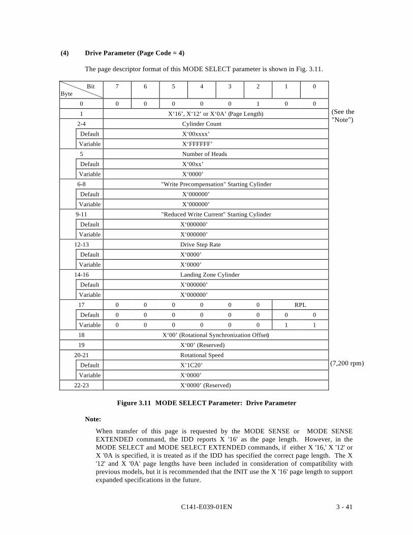
C141-E039-01EN 3 - 41
(4) Drive Parameter (Page Code = 4)
The page descriptor format of this MODE SELECT parameter is shown in Fig. 3.11.
BitByte
7 6 5 4 3 2 1 0
0 0 0 0 0 0 1 0 0
1 X‘16’, X‘12’ or X‘0A’ (Page Length)
2-4 Cylinder Count
Default X‘00xxxx’
Variable X‘FFFFFF’
5 Number of Heads
Default X‘00xx’
Variable X‘0000’
6-8 "Write Precompensation" Starting Cylinder
Default X‘000000’
Variable X’000000’
9-11 "Reduced Write Current" Starting Cylinder
Default X‘000000’
Variable X‘000000’
12-13 Drive Step Rate
Default X‘0000’
Variable X‘0000’
14-16 Landing Zone Cylinder
Default X‘000000’
Variable X‘000000’
17 0 0 0 0 0 0 RPL
Default 0 0 0 0 0 0 0 0
Variable 0 0 0 0 0 0 1 1
18 X‘00’ (Rotational Synchronization Offset)
19 X‘00’ (Reserved)
20-21 Rotational Speed
Default X’1C20’
Variable X‘0000’
22-23 X‘0000’ (Reserved)
Figure 3.11 MODE SELECT Parameter: Drive Parameter
Note:
When transfer of this page is requested by the MODE SENSE or MODE SENSEEXTENDED command, the IDD reports X '16' as the page length. However, in theMODE SELECT and MODE SELECT EXTENDED commands, if either X '16,' X '12' orX '0A is specified, it is treated as if the IDD has specified the correct page length. The X'12' and X '0A' page lengths have been included in consideration of compatibility withprevious models, but it is recommended that the INIT use the X '16' page length to supportexpanded specifications in the future.
(See the"Note")
(7,200 rpm)
C141-E039-01EN3 - 42
a. Cylinder Count
This parameter specifies the total number of cylinders configured in the "User Space" onthe disk media. This value includes the number of cylinders for alternate blocks specifiedin the "Alternate Track Count/Drive" parameter of the format parameters (Page code = 3),so caution should be used. This parameter can be changed, but the INIT must specify zeroor a value less than the maximum cylinder count that can be used as "User Space."
If zero is specified in this field, it is equivalent to specifying the either the maximumnumber of cylinders in the "User Space" or the number of cylinders necessary for rankingthe specified number of logical data blocks specified in the "Data block count" parameterin the block descriptor, whichever is smaller. Furthermore, if the specification of the "Datablock count" parameter in the block descriptor is also zero, the maximum number ofcylinder is set in this field.
On the other hand, if a value other than zero is specified in this field, the IDD processesthis parameter as shown below.
• When this page descriptor is specified together with a block descriptor in which avalue other than zero is specified in the "Data block count" parameter in the sameMODE SELECT or MODE SELECT EXTENDED command, and the value of thisparameter field does not match the value specified in the "Data block count"parameter in the block descriptor, the IDD performs rounding processing of theparameter with a range where it won't exceed the maximum number of cylinders, andsets the number of cylinders in this parameter that is necessary for ranking thespecified number of logical data blocks in the "Data block count" parameter of theblock descriptor (this rounding processing is not reported).
• When this page descriptor is specified together with a block descriptor in which zerois specified in the "Data block count" parameter, or when it is not specified togetherwith the block descriptor, the number of rankable logical data blocks is determined bythe value specified in this parameter field and the value specified in the Formatparameter (Page code = 3). Furthermore, when a value which exceeds the maximumcylinder count is specified in this parameter field, the IDD sets the maximum cylindercount in this parameter by rounding (down) processing of this parameter. Also, if thevalue specified in this parameter field less than or equal to the alternate cylinder countspecified in the "Alternate track count/drive" parameter in the Format parameters(Page code = 3), the IDD sets the (alternate cylinder count +1) in this parameter byrounding (up) processing. When the above rounding processing is performed, aCHECK CONDITION status (RECOVERED ERROR {= 1} / Rounded Parameter[37-00] is reported for that command. Therefore, if the number of cylindersconfigured in the "User Space" is clearly specified in this parameter, it is necessary forthe INIT to specify zero in the "Data block count" parameter in the block descriptor ortransfer this page descriptor without specifying the block descriptor.
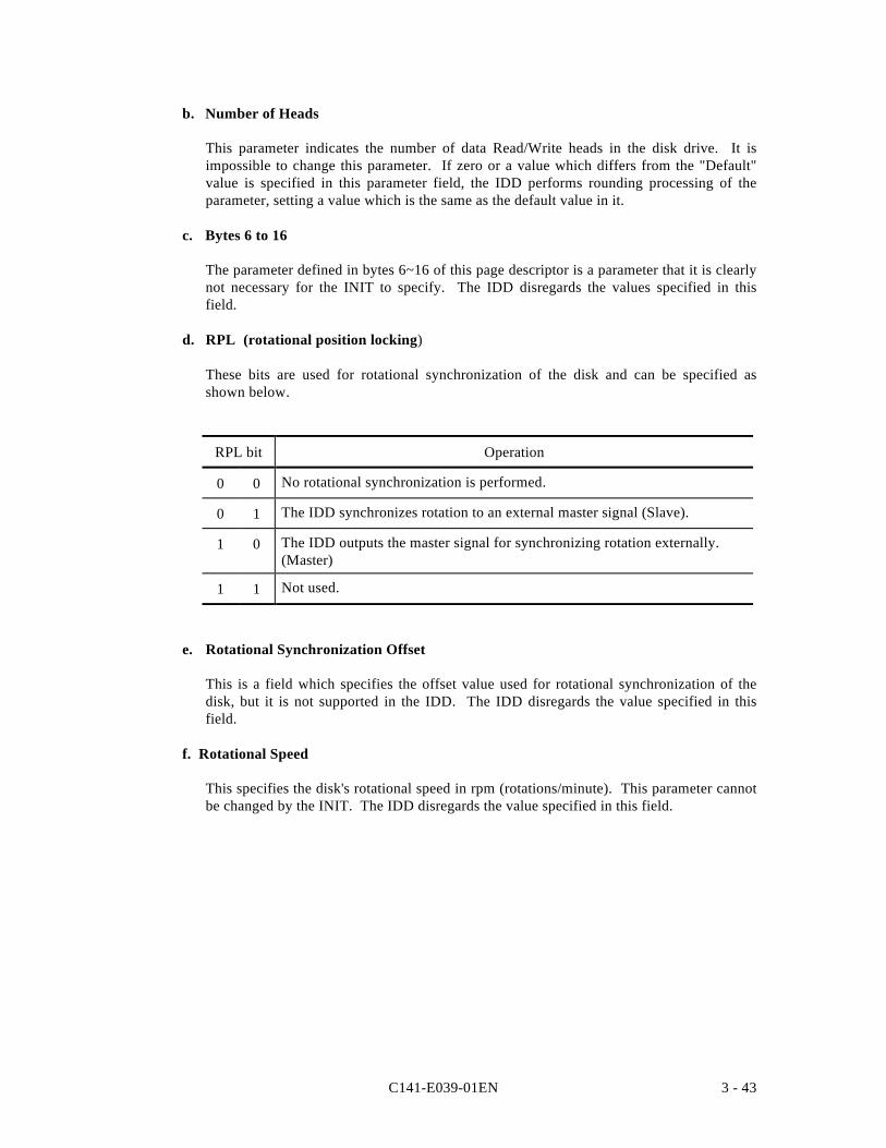
C141-E039-01EN 3 - 43
b. Number of Heads
This parameter indicates the number of data Read/Write heads in the disk drive. It isimpossible to change this parameter. If zero or a value which differs from the "Default"value is specified in this parameter field, the IDD performs rounding processing of theparameter, setting a value which is the same as the default value in it.
c. Bytes 6 to 16
The parameter defined in bytes 6~16 of this page descriptor is a parameter that it is clearlynot necessary for the INIT to specify. The IDD disregards the values specified in thisfield.
d. RPL (rotational position locking)
These bits are used for rotational synchronization of the disk and can be specified asshown below.
RPL bit Operation
0 0 No rotational synchronization is performed.
0 1 The IDD synchronizes rotation to an external master signal (Slave).
1 0 The IDD outputs the master signal for synchronizing rotation externally.(Master)
1 1 Not used.
e. Rotational Synchronization Offset
This is a field which specifies the offset value used for rotational synchronization of thedisk, but it is not supported in the IDD. The IDD disregards the value specified in thisfield.
f. Rotational Speed
This specifies the disk's rotational speed in rpm (rotations/minute). This parameter cannotbe changed by the INIT. The IDD disregards the value specified in this field.
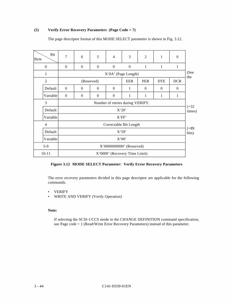
C141-E039-01EN3 - 44
(5) Verify Error Recovery Parameters (Page Code = 7)
The page descriptor format of this MODE SELECT parameter is shown in Fig. 3.12.
BitByte 7 6 5 4 3 2 1 0
0 0 0 0 0 0 1 1 1
1 X‘0A’ (Page Length)
2 (Reserved) EER PER DTE DCR
Default 0 0 0 0 1 0 0 0
Variable 0 0 0 0 1 1 1 1
3 Number of retries during VERIFY.
Default X‘20’
Variable X‘FF’
4 Correctable Bit Length
Default X‘59’
Variable X‘00’
5-9 X‘0000000000’ (Reserved)
10-11 X‘0000’ (Recovery Time Limit)
Figure 3.12 MODE SELECT Parameter: Verify Error Recovery Parameters
The error recovery parameters divided in this page descriptor are applicable for the followingcommands.
• VERIFY• WRITE AND VERIFY (Verify Operation)
Note:
If selecting the SCSI-1/CCS mode in the CHANGE DEFINITION command specification,use Page code = 1 (Read/Write Error Recovery Parameters) instead of this parameter.
(=89bits)
(=32times)
(SeetheNote.)
C141-E039-01EN 3 - 45
a. Error Recovery Flags
• EER (enable early recovery)• PER (post error)• DTE (disable transfer on error)• DCR (disable correction)
The definitions and functions of these control flags are the same as for the Read/WriteError Recovery Parameters. See item (1) concerning the details.
b. Number of retries during VERIFY
This parameter specifies the number of times reading of the disk media should be retriedwhen a "Data Check" type error is detected in a read operation. the number of retriesspecified by this parameter is the maximum number of times reading of each individualdata area in each logical data block is retried. The IDD retries reading the data area in eachdata block the specified number of times. When zero is specified in this field, retrying toread data from the disk is prohibited.
When X '06' is specified as the page length on Page 1, the IDD applies the value specifiedin the Number of retries during READ field on Page 1 to this field also.
c. Correctable Bit Length
This parameter indicates the burst error length (bit length) that can be applied for datacorrections according to the ECC. This parameter cannot be changed by the INIT.However, the IDD disregards the value specified in this parameter and operationsaccording to the "Default" value.
d. Recovery Time Limit
This parameter specifies the maximum time the TARG can used for error recoveryprocessing, as a 1 (s constant. The value specified in this parameter is the maximumpermissible error recovery processing time for an individual logical data block. Whenboth this parameter and the "Number of retries during VERIFY" parameter are specified,priority must be given to whichever parameter specifies the shortest time in its application.
The IDD does not support this parameter. The IDD disregards the value specified in thisparameter.
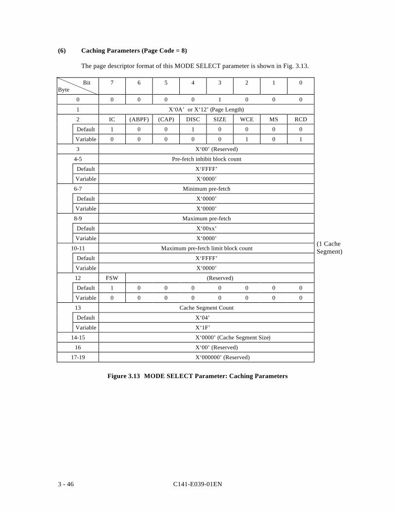
C141-E039-01EN3 - 46
(6) Caching Parameters (Page Code = 8)
The page descriptor format of this MODE SELECT parameter is shown in Fig. 3.13.
BitByte
7 6 5 4 3 2 1 0
0 0 0 0 0 1 0 0 0
1 X‘0A’ or X‘12’ (Page Length)
2 IC (ABPF) (CAP) DISC SIZE WCE MS RCD
Default 1 0 0 1 0 0 0 0
Variable 0 0 0 0 0 1 0 1
3 X‘00’ (Reserved)
4-5 Pre-fetch inhibit block count
Default X‘FFFF’
Variable X‘0000’
6-7 Minimum pre-fetch
Default X‘0000’
Variable X‘0000’
8-9 Maximum pre-fetch
Default X‘00xx’
Variable X‘0000’
10-11 Maximum pre-fetch limit block count
Default X‘FFFF’
Variable X‘0000’
12 FSW (Reserved)
Default 1 0 0 0 0 0 0 0
Variable 0 0 0 0 0 0 0 0
13 Cache Segment Count
Default X‘04’
Variable X‘1F’
14-15 X‘0000’ (Cache Segment Size)
16 X‘00’ (Reserved)
17-19 X‘000000’ (Reserved)
Figure 3.13 MODE SELECT Parameter: Caching Parameters
(1 CacheSegment)
C141-E039-01EN 3 - 47
The parameters defined in this page descriptor control the range of look-ahead data in theLook-Ahead cache feature and enable or disable the caching operation. See 2.2, "Look-AheadCache Feature" and 2.3, "Write Cache" concerning details of the Look-Ahead cache featureand parameter setting methods.
a. RCD (read cache disable)
This bit can be specified, and its operation is as specified.
This bit specifies whether or not to activate the cache operation for a read command.
"1" :Prohibits operation of the Look-Ahead cache function.
The IDD reads ahead all of the data requested by the READ command or READEXTENDED command from the disk and transfers it to the INIT. Moreover, it does notread ahead data blocks after the requested data.
"0" :Specifies operation of the Look-Ahead cache function.
If part or all of the data, including logical data blocks of headers, requested by a READcommand or READ EXTENDED command exists in the data buffer, the IDD transfers thatdata without accessing the disk. Also, depending on the instructions for the bytes beyondbyte 4 of the parameter page, it reads ahead the data blocks after the requested data in thedata buffer.
b. Multiple selection (MS)
This bit specifies how to specify the "minimum prefetch count" (bytes 6 and 7) and"maximum prefetch count" (bytes 8 and 9) parameters in this page descriptor.
1: The "minimum prefetch count" and "maximum prefetch count" parameters indicate amultiplier. The number of data blocks to be prefetch is calculated that the value in the"transfer byte count" in the CDB specified by the READ or READ EXTENDEDcommand X multiplier.
0: The "minimum prefetch count" and "maximum prefetch count" parameters indicatethe data block count to be prefetched with the logical data block count.
This bit cannot be changed, and the IDD ignores this bit specification and operatesaccording to the default value ('0').
c. WCE (write cache enable)
This bit can be specified, and its operation is as specified.
This bit specifies whether or not to activate the cache operation for a write command.
"1" :This enables the WRITE cache.
WRITE DATA remains in the buffer memory, the cache is made the object even for a readcommand, and when all of the write data has been received, "GOOD" status is reportedwithout disconnecting.
C141-E039-01EN3 - 48
Sequential writing is performed without waiting for rotation.
"0" :This prohibits operation of the WRITE cache function.
WRITE DATA remains in the buffer memory, the cache is not made the object even for a readcommand, and as soon as all the data has been written to the disk, "GOOD" status is reported.
d. SIZE (size enable)
"1" :Divides the data buffer in accordance with the value specified for the cache segmentsize (bytes 14, 15).
"0" :Divides the data buffer in accordance with the value specified for the number ofcache segments (byte 13).
This bit cannot be changed. The IDD disregards the specification in this bit and operatesaccording to the "Default" value (= "0").
e. DISC (discontinuity)
"1" :Even if a track switch occurs during Look-Ahead, the Look-Ahead operationcontinues without interruption.
"0" : Look-Ahead is terminated at the point where track switch occurs during Look-Ahead.
This bit cannot be changed. The IDD disregards the specification in this bit and operatesaccording to the "Default" value (= "1").
f. IC (initiator control enable)
"1" :Dividing of cache segments is according to the SIZE bit specification.
"0" : Dividing of the cache segments is performed by an algorithm that is inherent in the IDD.
This bit cannot be changed. The IDD disregards the specification in this bit and operatesaccording to the "Default" value (= "1").
g. Pre-fetch Inhibit Block Count
This parameter is used to selectively prohibit data Look-Ahead operations in the READcommand or the READ EXTENDED command. When the "Transfer block count"specified in the CDB of the READ command or the READ EXTENDED command isgreater than the value in this parameter, data Look-Ahead operations are not executed inthat command. This bit cannot be changed. The IDD disregards the specification in this bitand operates according to the "Default" value (= X 'FFFF').
h. Minimum Pre-fetch
This parameter specifies the minimum quantity of logical data blocks pre-fetched to thedata buffer with the READ command or READ EXTENDED command.
This parameter cannot be changed. The IDD disregards the specification in this field.
C141-E039-01EN 3 - 49
i. Maximum Pre-fetch
This parameter specifies the maximum quantity of logical data blocks pre-fetched to thedata buffer with the READ command or READ EXTENDED command.
The IDD varies the pre-fetch volume according to the volume of data requested by theREAD command or READ EXTENDED command. The value reported to the MODESENSE command always indicates the number of blocks corresponding to 1 cachesegment - 1.
This parameter cannot be changed. The IDD disregards the specification in this field.
j. Maximum Pre-fetch Control Block Count
This parameter specifies the maximum quantity of logical data blocks pre-fetched to thedata buffer with the READ command or READ EXTENDED command. In the IDD themaximum pre-fetch quantity cannot be limited.
This parameter cannot be changed. The IDD disregards the specification in this field.
k. FSW (force sequential write)
"1" : If the IDD writes multiple blocks, this indicates that data are recorded on the diskmedia in the order in which they are transferred from the INIT.
"0" : If the IDD writes multiple blocks, this indicates that data are recorded on the diskmedia with their order changed in order to complete the command in the fastesttime.
This bit cannot be changed. The IDD disregards the specification in this bit and operatesaccording to the "Default" value (="1").
l. Cache Segment Count
This parameter specifies the number of cache segments used by the IDD. This parameteris valid when the SIZE bit specification is "0."
The initiator can specify x01 to x10 in this parameter. When x00 is specified in thisparameter, the IDD performs rounding processing of the parameter. When a value greaterthan x10 is specified, the IDD performs rounding processing and sets x10. The defaultvalue of this parameter is "04" (=124K x 4).
This parameter indicates the same value for all initiators and if it is changed by anyinitiator, a UNIT ATTENTION condition (UNIT ATTENTION [=6] / Mode selectparameter changed [=2A-01] is generated for all the initiators that did not change it.
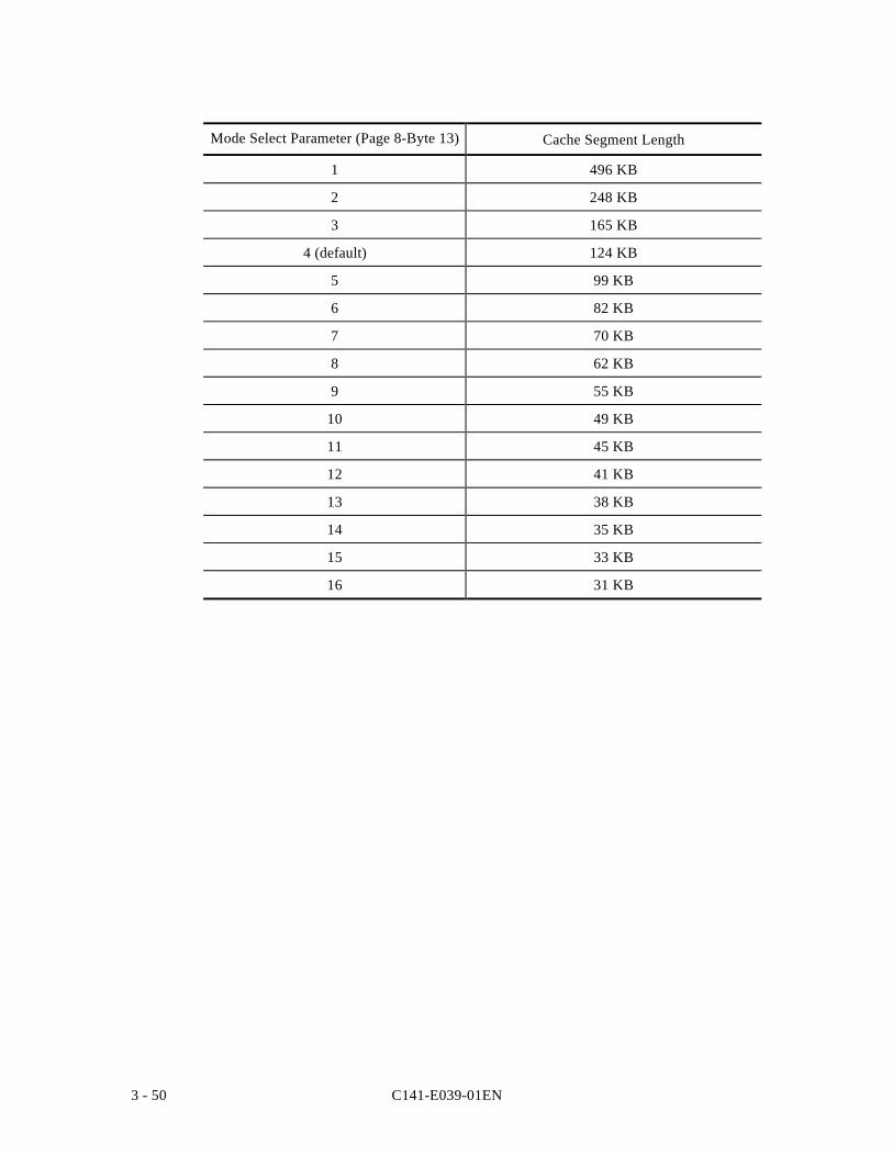
C141-E039-01EN3 - 50
Mode Select Parameter (Page 8-Byte 13) Cache Segment Length
1 496 KB
2 248 KB
3 165 KB
4 (default) 124 KB
5 99 KB
6 82 KB
7 70 KB
8 62 KB
9 55 KB
10 49 KB
11 45 KB
12 41 KB
13 38 KB
14 35 KB
15 33 KB
16 31 KB
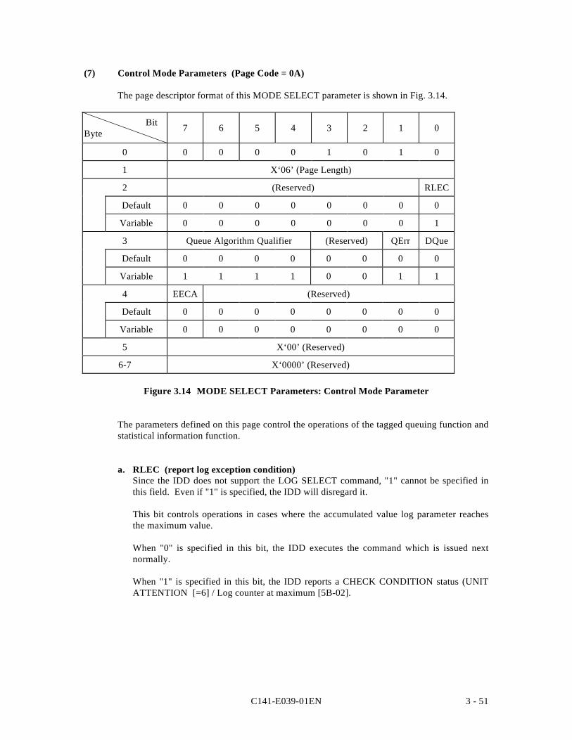
C141-E039-01EN 3 - 51
(7) Control Mode Parameters (Page Code = 0A)
The page descriptor format of this MODE SELECT parameter is shown in Fig. 3.14.
BitByte 7 6 5 4 3 2 1 0
0 0 0 0 0 1 0 1 0
1 X‘06’ (Page Length)
2 (Reserved) RLEC
Default 0 0 0 0 0 0 0 0
Variable 0 0 0 0 0 0 0 1
3 Queue Algorithm Qualifier (Reserved) QErr DQue
Default 0 0 0 0 0 0 0 0
Variable 1 1 1 1 0 0 1 1
4 EECA (Reserved)
Default 0 0 0 0 0 0 0 0
Variable 0 0 0 0 0 0 0 0
5 X‘00’ (Reserved)
6-7 X‘0000’ (Reserved)
Figure 3.14 MODE SELECT Parameters: Control Mode Parameter
The parameters defined on this page control the operations of the tagged queuing function andstatistical information function.
a. RLEC (report log exception condition)Since the IDD does not support the LOG SELECT command, "1" cannot be specified inthis field. Even if "1" is specified, the IDD will disregard it.
This bit controls operations in cases where the accumulated value log parameter reachesthe maximum value.
When "0" is specified in this bit, the IDD executes the command which is issued nextnormally.
When "1" is specified in this bit, the IDD reports a CHECK CONDITION status (UNITATTENTION [=6] / Log counter at maximum [5B-02].
C141-E039-01EN3 - 52
b. Queue Algorithm Qualifier
This parameter controls the execution order algorithm of a command issued together witha SIMPLE QUEUE TAG message.
When "0" is specified in this parameter, the IDD executes commands queued from eachINIT in the order in which they were received. However, the command execution orderfor the READ, READ EXTENDED and PRE-FETCH commands may be changed.
When "1" is specified in this parameter, the IDD executes queued commands by themethod selected by the IDD. At this time, the INIT must verify the correctness of the datathrough appropriate commands and QUEUE TAG messages.
c. QErr (queue error management)
This bit controls processing of commands queued after a sense hold state is canceled whenthe IDD is in the sense hold state.
When "0" is specified in this bit, the IDD, when it has been in any one of various sensehold states, then that sense hold state is cleared, continues executing the commands whichare queued by normal methods.
When "1" is specified in this bit, the IDD, when it has been in any one of various sensehold states, then that sense hold state is cleared, clears the commands which are queued.At this time, the IDD generates a UNIT ATTENTION condition (Command cleared byanother initiator =2F-00]) for each of the INITs that issued the commands which werecleared.
d. DQue (disable queuing)
This bit specifies whether the IDD will execute processing of tagged commands or not.
When "0" is specified in this bit, the IDD permits tagged queuing processing.
When "1" is specified in this bit, the IDD prohibits tagged queuing processing. The IDDclears queued commands and generates a UNIT ATTENTION condition (Commandcleared by another initiator =2F-00]) for each of the INITs that issued the commandswhich were cleared. After that, the when a QUEUE TAG message is received, it isrejected with a MESSAGE REJECT message and executed as an untagged command.
e. EECA (enable extended contingent alliance)
This bit specifies whether or not the ECA state is permitted.
"1" :The IDD supports the ECA state.
"0" :The IDD does not support the ECA state.
This bit cannot be changed. The IDD disregards the specification of this bit and operatesaccording to the "Default" value. (= "0").
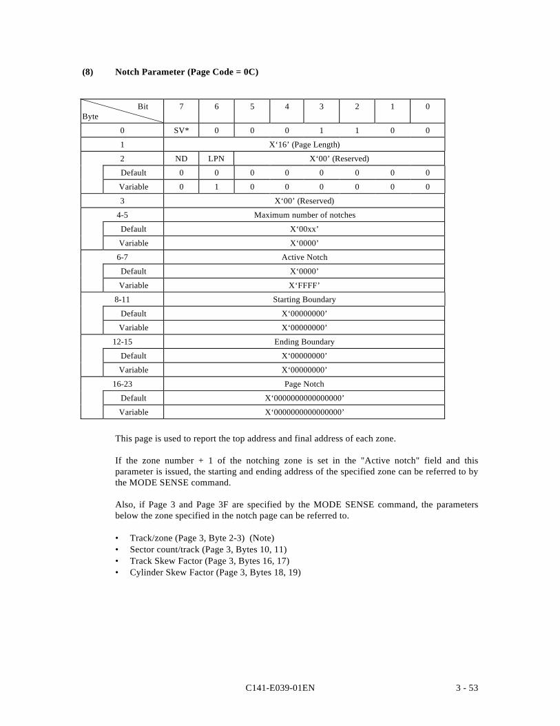
C141-E039-01EN 3 - 53
(8) Notch Parameter (Page Code = 0C)
BitByte
7 6 5 4 3 2 1 0
0 SV* 0 0 0 1 1 0 0
1 X‘16’ (Page Length)
2 ND LPN X‘00’ (Reserved)
Default 0 0 0 0 0 0 0 0
Variable 0 1 0 0 0 0 0 0
3 X‘00’ (Reserved)
4-5 Maximum number of notches
Default X‘00xx’
Variable X‘0000’
6-7 Active Notch
Default X‘0000’
Variable X‘FFFF’
8-11 Starting Boundary
Default X‘00000000’
Variable X‘00000000’
12-15 Ending Boundary
Default X‘00000000’
Variable X‘00000000’
16-23 Page Notch
Default X‘0000000000000000’
Variable X‘0000000000000000’
This page is used to report the top address and final address of each zone.
If the zone number + 1 of the notching zone is set in the "Active notch" field and thisparameter is issued, the starting and ending address of the specified zone can be referred to bythe MODE SENSE command.
Also, if Page 3 and Page 3F are specified by the MODE SENSE command, the parametersbelow the zone specified in the notch page can be referred to.
• Track/zone (Page 3, Byte 2-3) (Note)• Sector count/track (Page 3, Bytes 10, 11)• Track Skew Factor (Page 3, Bytes 16, 17)• Cylinder Skew Factor (Page 3, Bytes 18, 19)
C141-E039-01EN3 - 54
Note
Normally, the number of tracks (logical heads) per cylinder is set in the track count/zone,but in the case of notching only, the total track count (number of cylinders in the zone xnumber of logical heads) of the affected zone is reported.
If this parameter is issued, only the format parameter of the zone specified by the MODESENSE command can be referred to without changing the number of accessible blocks.
Also, if a MODE SENSE command with a SP = "1" that includes a notch page is issued, thecurrent value is reported for this page and the zone value which is the object is reported if Page3 is notched, then the command is terminated normally. However, in the case of theFORMAT CORRUPTED state, caution is necessary because the value following changing ofthe Format parameter is reported.
The contents of each parameter are explained below.
• ND (Notch Drive)
"0" :Since the device is not in the notched state, "0" is reported for LPN, active notch,starting boundary and ending boundary.
"1" :Since the device is in the notched state, the starting boundary and ending boundaryfor the zone number (+1) shown in the active notch is set in the format specified inthe LPN Bit.
• LPN (Logical or Physical Notch)
"0" :This shows that the boundary address is based on the physical address format. Atthat time, the higher order 3 bytes show the logical cylinder number and the lowestorder byte shows the logical head number.
"1" :This shows that the boundary address is based on the 4-byte logical block addressformat.
This bit is a bit which must be set during MODE SELECT.
• Maximum Number of Notches
This indicates the number of device zones. 14 zones (x0E) are set in the ALLEGRO 4 and12 (x0C) zones are set in the ALLEGRO 4'.
• Active Notch
This specifies the zone number (+1) of a notching zone. If "0" is specified, the page andparameter changed by the notch page, and the notch page itself, are changed to the initialvalue. If a value which exceeds the maximum number of notches has been specified, thetest ends by "CHECK CONDITION" status (ILLEGAL REQUEST [=5]/Invalid parameterin List [=26-00]).
This field is a field which must be set during MODE SELECT.
C141-E039-01EN 3 - 55
• Starting Boundary
This field is enabled by the MODE SENSE command. This field is enabled when ND=1and the top address of the zone (+1) indicated by the active notch shows thelogical/physical block format.
• Ending Boundary
This field is valid in the MODE SENSE command. It is valid when ND=1, and the finaladdress of the zone (+1) shown by the active notch is indicated in the physical/logicalblock format.
• Page Notch (Not Supported)
This is a bit map which shows whether or not other mode pages are being changed if thedevice is notched. This device does not support this function. If it is specified, the IDDdisregards this value.
The IDD does not support the Standby condition. The "Standby" bit specification and the"Standby Condition Timer" specification are disregarded.
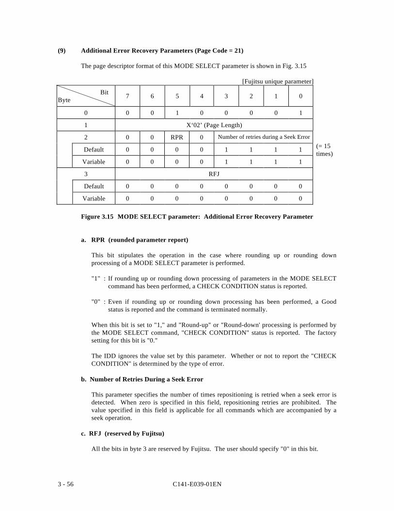
C141-E039-01EN3 - 56
(9) Additional Error Recovery Parameters (Page Code = 21)
The page descriptor format of this MODE SELECT parameter is shown in Fig. 3.15
[Fujitsu unique parameter]
BitByte 7 6 5 4 3 2 1 0
0 0 0 1 0 0 0 0 1
1 X‘02’ (Page Length)
2 0 0 RPR 0 Number of retries during a Seek Error
Default 0 0 0 0 1 1 1 1
Variable 0 0 0 0 1 1 1 1
3 RFJ
Default 0 0 0 0 0 0 0 0
Variable 0 0 0 0 0 0 0 0
Figure 3.15 MODE SELECT parameter: Additional Error Recovery Parameter
a. RPR (rounded parameter report)
This bit stipulates the operation in the case where rounding up or rounding downprocessing of a MODE SELECT parameter is performed.
"1" : If rounding up or rounding down processing of parameters in the MODE SELECTcommand has been performed, a CHECK CONDITION status is reported.
"0" : Even if rounding up or rounding down processing has been performed, a Goodstatus is reported and the command is terminated normally.
When this bit is set to "1," and "Round-up" or "Round-down' processing is performed bythe MODE SELECT command, "CHECK CONDITION" status is reported. The factorysetting for this bit is "0."
The IDD ignores the value set by this parameter. Whether or not to report the "CHECKCONDITION" is determined by the type of error.
b. Number of Retries During a Seek Error
This parameter specifies the number of times repositioning is retried when a seek error isdetected. When zero is specified in this field, repositioning retries are prohibited. Thevalue specified in this field is applicable for all commands which are accompanied by aseek operation.
c. RFJ (reserved by Fujitsu)
All the bits in byte 3 are reserved by Fujitsu. The user should specify "0" in this bit.
(= 15times)
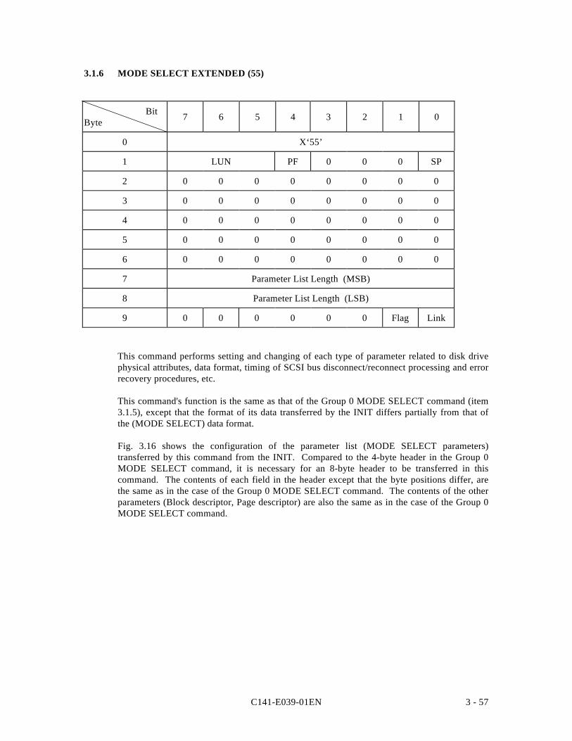
C141-E039-01EN 3 - 57
3.1.6 MODE SELECT EXTENDED (55)
BitByte 7 6 5 4 3 2 1 0
0 X‘55’
1 LUN PF 0 0 0 SP
2 0 0 0 0 0 0 0 0
3 0 0 0 0 0 0 0 0
4 0 0 0 0 0 0 0 0
5 0 0 0 0 0 0 0 0
6 0 0 0 0 0 0 0 0
7 Parameter List Length (MSB)
8 Parameter List Length (LSB)
9 0 0 0 0 0 0 Flag Link
This command performs setting and changing of each type of parameter related to disk drivephysical attributes, data format, timing of SCSI bus disconnect/reconnect processing and errorrecovery procedures, etc.
This command's function is the same as that of the Group 0 MODE SELECT command (item3.1.5), except that the format of its data transferred by the INIT differs partially from that ofthe (MODE SELECT) data format.
Fig. 3.16 shows the configuration of the parameter list (MODE SELECT parameters)transferred by this command from the INIT. Compared to the 4-byte header in the Group 0MODE SELECT command, it is necessary for an 8-byte header to be transferred in thiscommand. The contents of each field in the header except that the byte positions differ, arethe same as in the case of the Group 0 MODE SELECT command. The contents of the otherparameters (Block descriptor, Page descriptor) are also the same as in the case of the Group 0MODE SELECT command.
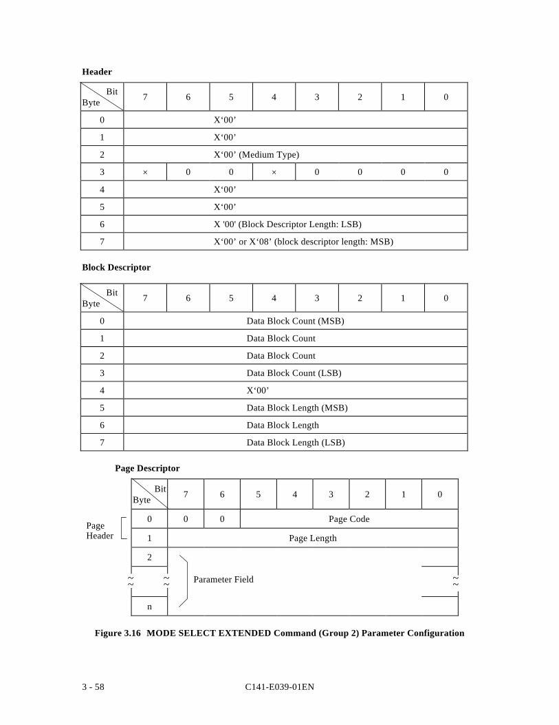
C141-E039-01EN3 - 58
Header
BitByte 7 6 5 4 3 2 1 0
0 X‘00’
1 X‘00’
2 X‘00’ (Medium Type)
3 × 0 0 × 0 0 0 0
4 X‘00’
5 X‘00’
6 X '00' (Block Descriptor Length: LSB)
7 X‘00’ or X‘08’ (block descriptor length: MSB)
Block Descriptor
BitByte 7 6 5 4 3 2 1 0
0 Data Block Count (MSB)
1 Data Block Count
2 Data Block Count
3 Data Block Count (LSB)
4 X‘00’
5 Data Block Length (MSB)
6 Data Block Length
7 Data Block Length (LSB)
Page Descriptor
BitByte 7 6 5 4 3 2 1 0
0 0 0 Page Code
1 Page Length
2
n
Figure 3.16 MODE SELECT EXTENDED Command (Group 2) Parameter Configuration
~~ ~~ ~~
PageHeader
Parameter Field
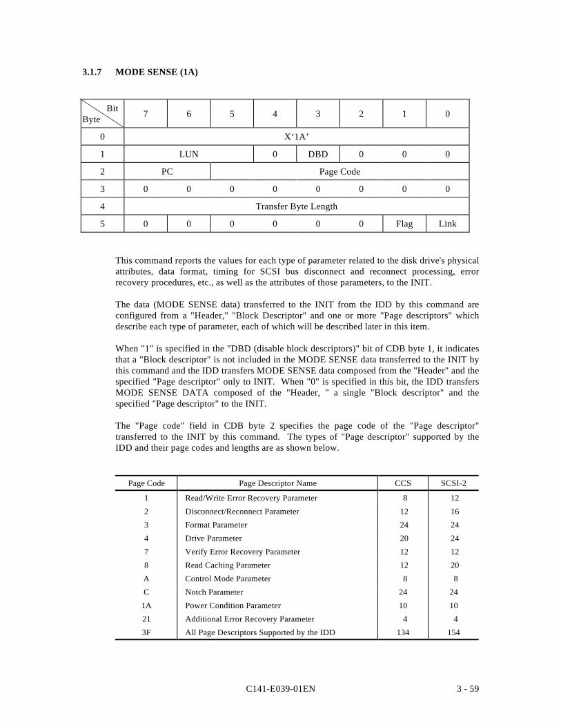
C141-E039-01EN 3 - 59
3.1.7 MODE SENSE (1A)
BitByte 7 6 5 4 3 2 1 0
0 X‘1A’
1 LUN 0 DBD 0 0 0
2 PC Page Code
3 0 0 0 0 0 0 0 0
4 Transfer Byte Length
5 0 0 0 0 0 0 Flag Link
This command reports the values for each type of parameter related to the disk drive's physicalattributes, data format, timing for SCSI bus disconnect and reconnect processing, errorrecovery procedures, etc., as well as the attributes of those parameters, to the INIT.
The data (MODE SENSE data) transferred to the INIT from the IDD by this command areconfigured from a "Header," "Block Descriptor" and one or more "Page descriptors" whichdescribe each type of parameter, each of which will be described later in this item.
When "1" is specified in the "DBD (disable block descriptors)" bit of CDB byte 1, it indicatesthat a "Block descriptor" is not included in the MODE SENSE data transferred to the INIT bythis command and the IDD transfers MODE SENSE data composed from the "Header" and thespecified "Page descriptor" only to INIT. When "0" is specified in this bit, the IDD transfersMODE SENSE DATA composed of the "Header, " a single "Block descriptor" and thespecified "Page descriptor" to the INIT.
The "Page code" field in CDB byte 2 specifies the page code of the "Page descriptor"transferred to the INIT by this command. The types of "Page descriptor" supported by theIDD and their page codes and lengths are as shown below.
Page Code Page Descriptor Name CCS SCSI-2
1 Read/Write Error Recovery Parameter 8 12
2 Disconnect/Reconnect Parameter 12 16
3 Format Parameter 24 24
4 Drive Parameter 20 24
7 Verify Error Recovery Parameter 12 12
8 Read Caching Parameter 12 20
A Control Mode Parameter 8 8
C Notch Parameter 24 24
1A Power Condition Parameter 10 10
21 Additional Error Recovery Parameter 4 4
3F All Page Descriptors Supported by the IDD 134 154
C141-E039-01EN3 - 60
When the value specified in the "Page code" field is other than X '3F', the specified "Pagedescriptor" only is transferred to the INIT, and when X '3F' is specified, all the "Pagedescriptors" supported by the IDD are transferred to the INIT in the ascending order of thepage code, but if SCSI-1/CCS is specified by the CHANGE DEFINITION command (SCSIlevel), Page code 7, Page code 8 and Page code A are not transferred. Also, when X '00' isspecified in the "Page code field," the "Page descriptor" is not transferred. If page codes otherthan the abovementioned ones ("Page descriptors" which are not supported by the IDD) arespecified, the command is terminated with a CHECK CONDITION status (ILLEGALREQUEST [=5] / Invalid field in CDB [=24-00]).
Also the "PC (page control)" field in CDB byte 2 specifies the type of parameter value in the"Page descriptor" transferred to the INIT by this command, as shown in Table 3.2.
Note:
Even in cases where the value specified in the MODE SELECT or MODE SELECTEXTENDED command is described in Table 3.2 as the value reported to the INIT by thiscommand, if parameter rounding processing is applied by the IDD, or in cases of aparameter or bit with a specified value that is disregarded, different values than thosespecified by the INIT will be reported. For details, see the descriptions of each pagedescriptor (in item 3.1.5). Also, "0" is reported in byte positions and bit positions whichare reserved in each page descriptor.
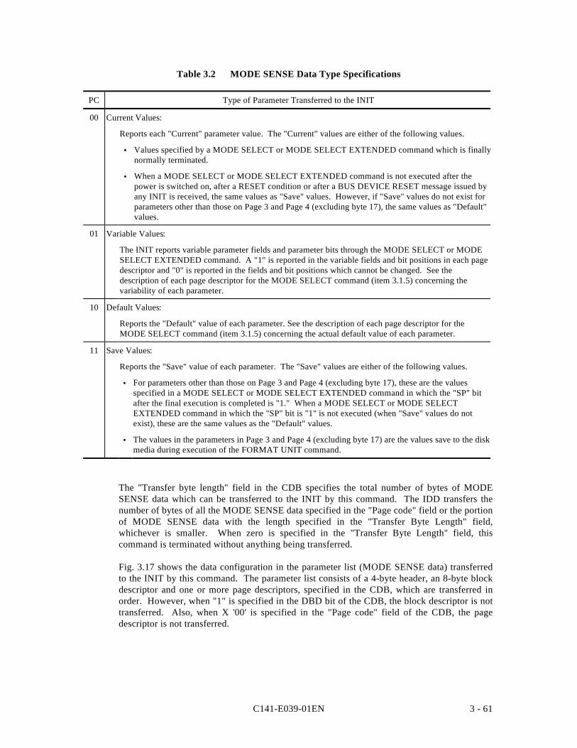
C141-E039-01EN 3 - 61
Table 3.2 MODE SENSE Data Type Specifications
PC Type of Parameter Transferred to the INIT
00 Current Values:
Reports each "Current" parameter value. The "Current" values are either of the following values.
• Values specified by a MODE SELECT or MODE SELECT EXTENDED command which is finallynormally terminated.
• When a MODE SELECT or MODE SELECT EXTENDED command is not executed after thepower is switched on, after a RESET condition or after a BUS DEVICE RESET message issued byany INIT is received, the same values as "Save" values. However, if "Save" values do not exist forparameters other than those on Page 3 and Page 4 (excluding byte 17), the same values as "Default"values.
01 Variable Values:
The INIT reports variable parameter fields and parameter bits through the MODE SELECT or MODESELECT EXTENDED command. A "1" is reported in the variable fields and bit positions in each pagedescriptor and "0" is reported in the fields and bit positions which cannot be changed. See thedescription of each page descriptor for the MODE SELECT command (item 3.1.5) concerning thevariability of each parameter.
10 Default Values:
Reports the "Default" value of each parameter. See the description of each page descriptor for theMODE SELECT command (item 3.1.5) concerning the actual default value of each parameter.
11 Save Values:
Reports the "Save" value of each parameter. The "Save" values are either of the following values.
• For parameters other than those on Page 3 and Page 4 (excluding byte 17), these are the valuesspecified in a MODE SELECT or MODE SELECT EXTENDED command in which the "SP" bitafter the final execution is completed is "1." When a MODE SELECT or MODE SELECTEXTENDED command in which the "SP" bit is "1" is not executed (when "Save" values do notexist), these are the same values as the "Default" values.
• The values in the parameters in Page 3 and Page 4 (excluding byte 17) are the values save to the diskmedia during execution of the FORMAT UNIT command.
The "Transfer byte length" field in the CDB specifies the total number of bytes of MODESENSE data which can be transferred to the INIT by this command. The IDD transfers thenumber of bytes of all the MODE SENSE data specified in the "Page code" field or the portionof MODE SENSE data with the length specified in the "Transfer Byte Length" field,whichever is smaller. When zero is specified in the "Transfer Byte Length" field, thiscommand is terminated without anything being transferred.
Fig. 3.17 shows the data configuration in the parameter list (MODE SENSE data) transferredto the INIT by this command. The parameter list consists of a 4-byte header, an 8-byte blockdescriptor and one or more page descriptors, specified in the CDB, which are transferred inorder. However, when "1" is specified in the DBD bit of the CDB, the block descriptor is nottransferred. Also, when X '00' is specified in the "Page code" field of the CDB, the pagedescriptor is not transferred.
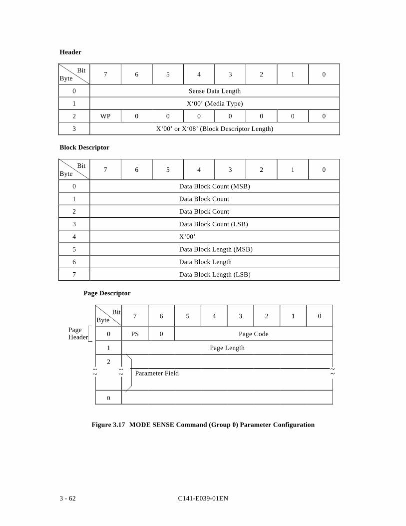
C141-E039-01EN3 - 62
Header
BitByte 7 6 5 4 3 2 1 0
0 Sense Data Length
1 X‘00’ (Media Type)
2 WP 0 0 0 0 0 0 0
3 X‘00’ or X‘08’ (Block Descriptor Length)
Block Descriptor
BitByte 7 6 5 4 3 2 1 0
0 Data Block Count (MSB)
1 Data Block Count
2 Data Block Count
3 Data Block Count (LSB)
4 X‘00’
5 Data Block Length (MSB)
6 Data Block Length
7 Data Block Length (LSB)
Page Descriptor
BitByte 7 6 5 4 3 2 1 0
0 PS 0 Page Code
1 Page Length
2
n
Figure 3.17 MODE SENSE Command (Group 0) Parameter Configuration
~~ ~~~~
PageHeader
Parameter Field
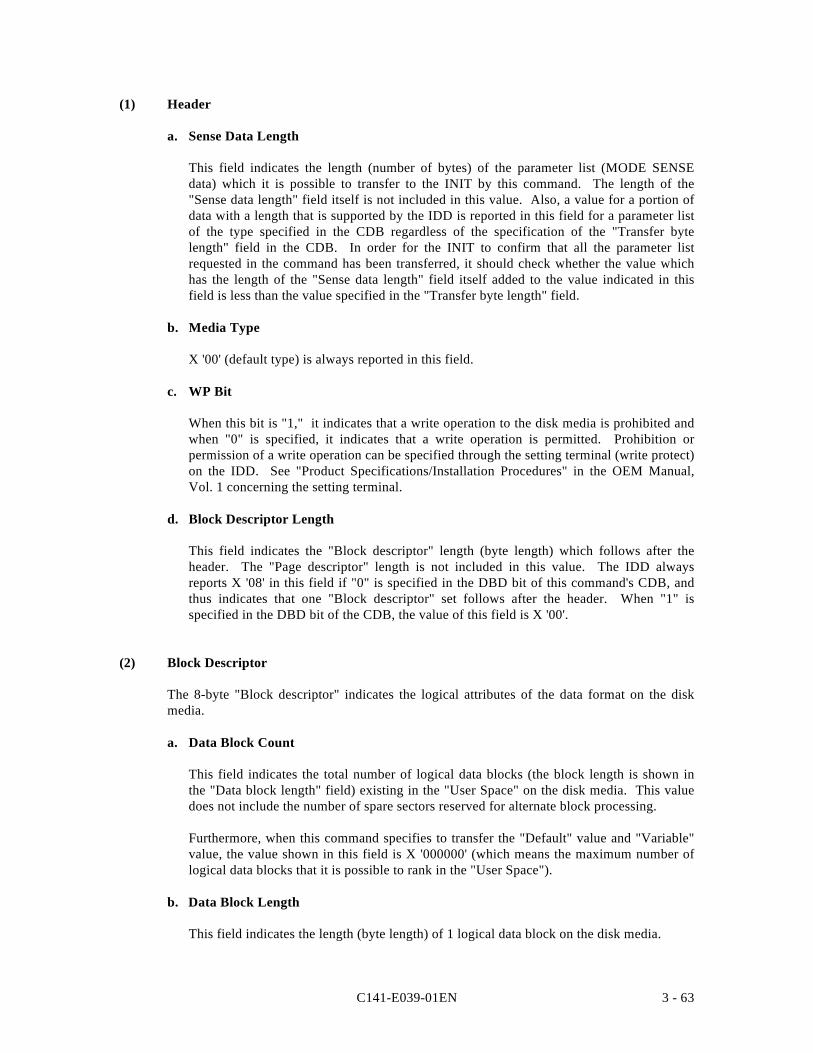
C141-E039-01EN 3 - 63
(1) Header
a. Sense Data Length
This field indicates the length (number of bytes) of the parameter list (MODE SENSEdata) which it is possible to transfer to the INIT by this command. The length of the"Sense data length" field itself is not included in this value. Also, a value for a portion ofdata with a length that is supported by the IDD is reported in this field for a parameter listof the type specified in the CDB regardless of the specification of the "Transfer bytelength" field in the CDB. In order for the INIT to confirm that all the parameter listrequested in the command has been transferred, it should check whether the value whichhas the length of the "Sense data length" field itself added to the value indicated in thisfield is less than the value specified in the "Transfer byte length" field.
b. Media Type
X '00' (default type) is always reported in this field.
c. WP Bit
When this bit is "1," it indicates that a write operation to the disk media is prohibited andwhen "0" is specified, it indicates that a write operation is permitted. Prohibition orpermission of a write operation can be specified through the setting terminal (write protect)on the IDD. See "Product Specifications/Installation Procedures" in the OEM Manual,Vol. 1 concerning the setting terminal.
d. Block Descriptor Length
This field indicates the "Block descriptor" length (byte length) which follows after theheader. The "Page descriptor" length is not included in this value. The IDD alwaysreports X '08' in this field if "0" is specified in the DBD bit of this command's CDB, andthus indicates that one "Block descriptor" set follows after the header. When "1" isspecified in the DBD bit of the CDB, the value of this field is X '00'.
(2) Block Descriptor
The 8-byte "Block descriptor" indicates the logical attributes of the data format on the diskmedia.
a. Data Block Count
This field indicates the total number of logical data blocks (the block length is shown inthe "Data block length" field) existing in the "User Space" on the disk media. This valuedoes not include the number of spare sectors reserved for alternate block processing.
Furthermore, when this command specifies to transfer the "Default" value and "Variable"value, the value shown in this field is X '000000' (which means the maximum number oflogical data blocks that it is possible to rank in the "User Space").
b. Data Block Length
This field indicates the length (byte length) of 1 logical data block on the disk media.
C141-E039-01EN3 - 64
(3) Page Descriptor
The "Page descriptor" is configured from a parameter field which follows a 2-byte pageheader, and is divided into units called "Page" for each parameter's functional attributes. Seethe description of the MODE SELECT command (item 3.1.5) concerning the configuration ofeach page descriptor and their contents.
a. PS Bit
When this bit is "1," the parameter value defined in that "Page descriptor" can be saved onthe disk media, and when it is "0", it indicates that this is a parameter which cannot besaved to the disk. It is possible to save all the "Page descriptors" supported by the IDD.However, "1" is always indicated in this bit for all "Page descriptors" transferred by thiscommand.
b. Page Length
This field indicates the length of the parameter field (number of bytes) from byte 2,excluding the page header of that "Page descriptor." The IDD always shows a value in thisfield which is the same as the length defined in that "Page descriptor" regardless of thetype of parameter requested in the "PC (page control)" field of the CDB, and reports all theparameter fields that "Page descriptor" in byte 2 and subsequent bytes.
c. Parameter Field
The parameter field in byte 2 and subsequent bytes, indicates parameter values of the type(current values, variable values, default values or save values) requested in the "PC (pagecontrol)" field of the CDB. See the description of the MODE SELECT command (item3.1.5) concerning the definition of each parameter, "Default" values and "Variable" values.
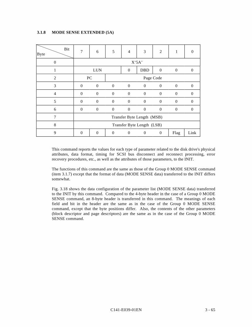
C141-E039-01EN 3 - 65
3.1.8 MODE SENSE EXTENDED (5A)
BitByte 7 6 5 4 3 2 1 0
0 X‘5A’
1 LUN 0 DBD 0 0 0
2 PC Page Code
3 0 0 0 0 0 0 0 0
4 0 0 0 0 0 0 0 0
5 0 0 0 0 0 0 0 0
6 0 0 0 0 0 0 0 0
7 Transfer Byte Length (MSB)
8 Transfer Byte Length (LSB)
9 0 0 0 0 0 0 Flag Link
This command reports the values for each type of parameter related to the disk drive's physicalattributes, data format, timing for SCSI bus disconnect and reconnect processing, errorrecovery procedures, etc., as well as the attributes of those parameters, to the INIT.
The functions of this command are the same as those of the Group 0 MODE SENSE command(item 3.1.7) except that the format of data (MODE SENSE data) transferred to the INIT differssomewhat.
Fig. 3.18 shows the data configuration of the parameter list (MODE SENSE data) transferredto the INIT by this command. Compared to the 4-byte header in the case of a Group 0 MODESENSE command, an 8-byte header is transferred in this command. The meanings of eachfield and bit in the header are the same as in the case of the Group 0 MODE SENSEcommand, except that the byte positions differ. Also, the contents of the other parameters(block descriptor and page descriptors) are the same as in the case of the Group 0 MODESENSE command.
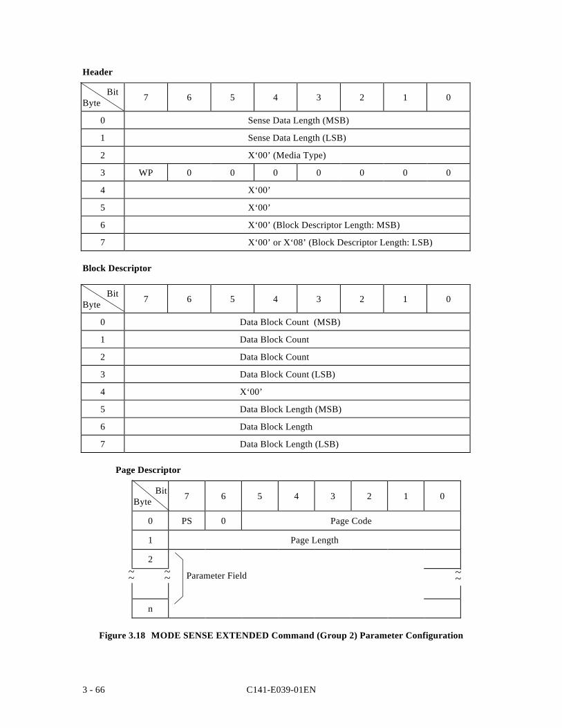
C141-E039-01EN3 - 66
Header
BitByte 7 6 5 4 3 2 1 0
0 Sense Data Length (MSB)
1 Sense Data Length (LSB)
2 X‘00’ (Media Type)
3 WP 0 0 0 0 0 0 0
4 X‘00’
5 X‘00’
6 X‘00’ (Block Descriptor Length: MSB)
7 X‘00’ or X‘08’ (Block Descriptor Length: LSB)
Block Descriptor
BitByte 7 6 5 4 3 2 1 0
0 Data Block Count (MSB)
1 Data Block Count
2 Data Block Count
3 Data Block Count (LSB)
4 X‘00’
5 Data Block Length (MSB)
6 Data Block Length
7 Data Block Length (LSB)
Page Descriptor
BitByte 7 6 5 4 3 2 1 0
0 PS 0 Page Code
1 Page Length
2
n
Figure 3.18 MODE SENSE EXTENDED Command (Group 2) Parameter Configuration
~~ ~~ ~~Parameter Field
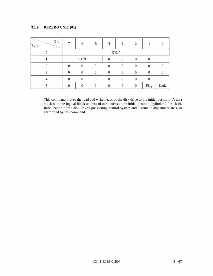
C141-E039-01EN 3 - 67
3.1.9 REZERO UNIT (01)
BitByte 7 6 5 4 3 2 1 0
0 X‘01’
1 LUN 0 0 0 0 0
2 0 0 0 0 0 0 0 0
3 0 0 0 0 0 0 0 0
4 0 0 0 0 0 0 0 0
5 0 0 0 0 0 0 Flag Link
This command moves the read and write heads of the disk drive to the initial position. A datablock with the logical block address of zero exists at the initial position (cylinder 0 / track 0).Initialization of the disk drive's positioning control system and automatic adjustment are alsoperformed by this command.
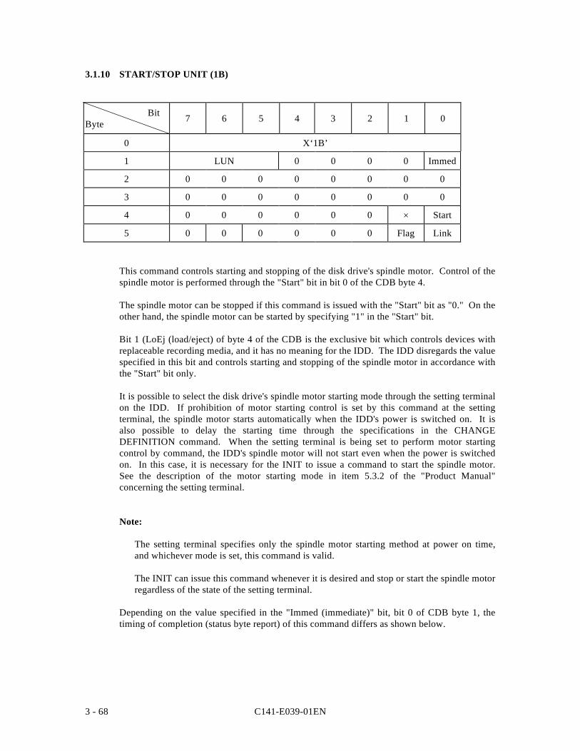
C141-E039-01EN3 - 68
3.1.10 START/STOP UNIT (1B)
BitByte 7 6 5 4 3 2 1 0
0 X‘1B’
1 LUN 0 0 0 0 Immed
2 0 0 0 0 0 0 0 0
3 0 0 0 0 0 0 0 0
4 0 0 0 0 0 0 × Start
5 0 0 0 0 0 0 Flag Link
This command controls starting and stopping of the disk drive's spindle motor. Control of thespindle motor is performed through the "Start" bit in bit 0 of the CDB byte 4.
The spindle motor can be stopped if this command is issued with the "Start" bit as "0." On theother hand, the spindle motor can be started by specifying "1" in the "Start" bit.
Bit 1 (LoEj (load/eject) of byte 4 of the CDB is the exclusive bit which controls devices withreplaceable recording media, and it has no meaning for the IDD. The IDD disregards the valuespecified in this bit and controls starting and stopping of the spindle motor in accordance withthe "Start" bit only.
It is possible to select the disk drive's spindle motor starting mode through the setting terminalon the IDD. If prohibition of motor starting control is set by this command at the settingterminal, the spindle motor starts automatically when the IDD's power is switched on. It isalso possible to delay the starting time through the specifications in the CHANGEDEFINITION command. When the setting terminal is being set to perform motor startingcontrol by command, the IDD's spindle motor will not start even when the power is switchedon. In this case, it is necessary for the INIT to issue a command to start the spindle motor.See the description of the motor starting mode in item 5.3.2 of the "Product Manual"concerning the setting terminal.
Note:
The setting terminal specifies only the spindle motor starting method at power on time,and whichever mode is set, this command is valid.
The INIT can issue this command whenever it is desired and stop or start the spindle motorregardless of the state of the setting terminal.
Depending on the value specified in the "Immed (immediate)" bit, bit 0 of CDB byte 1, thetiming of completion (status byte report) of this command differs as shown below.
C141-E039-01EN 3 - 69
a. In the case of the Start Specification ("Start" bit = "1")
• When the "Immed" bit is "1," simply by instructing starting of the spindle motor, aGOOD status is reported without waiting until the disk drive is in the Ready state, andcommand execution is completed.
• When the "Immed" bit is "0," the status byte is reported, and command execution iscompleted, at the point when the disk drive has entered the Ready state after thespindle motor has started.
b. In the case of the Stop Specification ("Start" bit = "0")
• When the "Immed" bit is "1," simply by instructing stopping of the spindle motor, theGOOD status is reported and command execution is completed.
• When the "Immed" bit is "0," the status byte is reported, and command execution iscompleted, after the spindle motor is in the stopped state.
Notes:
1. When this command with the Start instruction is issued with a link to anothercommand, the specification in the "Immed" bit should be "0." If "1" is specified forthe "Immed" bit, ordinarily, the disk drive is still not in the Ready state at the pointwhen this command is completed, so a linked command cannot be executed normally
2. Even if "1" is specified in the "Immed" bit of this command, if other commands arealready queued and another command exists which is already being executed, thiscommand is placed on the queue and disconnect processing is performed. Therefore,even if "1" is specified in the "Immed" bit, the status will not necessarily be reportedimmediately after the COMMAND phase.
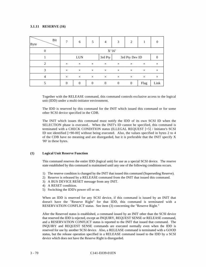
C141-E039-01EN3 - 70
3.1.11 RESERVE (16)
BitByte
7 6 5 4 3 2 1 0
0 X‘16’
1 LUN 3rd Pty 3rd Pty Dev ID 0
2 × × × × × × × ×
3 × × × × × × × ×
4 × × × × × × × ×
5 0 0 0 0 0 0 Flag Link
Together with the RELEASE command, this command controls exclusive access to the logicalunit (IDD) under a multi-initiator environment.
The IDD is reserved by this command for the INIT which issued this command or for someother SCSI device specified in the CDB.
The INIT which issues this command must notify the IDD of its own SCSI ID when theSELECTION phase is executed.. When the INIT's ID cannot be specified, this command isterminated with a CHECK CONDITION status (ILLEGAL REQUEST [=5] / Initiator's SCSIID not identified [=90-00] without being executed. Also, the values specified in bytes 2 to 4of the CDB have no meaning and are disregarded, but it is preferable that the INIT specify X'00' in these bytes.
(1) Logical Unit Reserve Function
This command reserves the entire IDD (logical unit) for use as a special SCSI device. The reservestate established by this command is maintained until any one of the following conditions occurs.
1) The reserve condition is changed by the INIT that issued this command (Superseding Reserve).2) Reserve is released by a RELEASE command from the INIT that issued this command.3) A BUS DEVICE RESET message from any INIT.4) A RESET condition.5) Switching the IDD's power off or on.
When an IDD is reserved for any SCSI device, if this command is issued by an INIT thatdoesn't have the "Reserve Right" for that IDD, this command is terminated with aRESERVATION CONFLICT status. See item (3) concerning the "Reserve Right."
After the Reserved status is established, a command issued by an INIT other than the SCSI devicethat reserved the IDD is rejected, except an INQUIRY, REQUEST SENSE or RELEASE command,and a RESERVATION CONFLICT status is reported to the INIT that issued that command. TheINQUIRY and REQUEST SENSE commands are executed normally even when the IDD isreserved for use by another SCSI device. Also, a RELEASE command is terminated with a GOODstatus, but the release operation specified in a RELEASE command issued to the IDD by a SCSIdevice which does not have the Reserve Right is disregarded.
C141-E039-01EN 3 - 71
(2) Reserve Right and Third Party Reserve Function
If the "3rd Pty" bit in byte 1 of the CDB is "0," the IDD is reserved by the INIT which issuedthis command and that INIT has the Reserve right for the IDD.
If the "3rd Pty" bit is "1," the third party reserve function is specified. An INIT whichspecifies the third party reserve function and issues this command can reserve the IDD for useby another SCSI device. In this case, this command reserves the IDD for the SCSI device(called the third party device) with the SCSI ID specified in the "3rd Pty Dev ID" field in byte1 of the CDB. Even it the IDD is reserved for another SCSI device using the third partyreserve function the reserve right for that ID resides with the INIT that issued this command.Therefore, in order to release that reserve state, it is necessary for the INIT that issued thiscommand to issue a RELEASE command (shown in item 3.1.13) with the third party releasefunction specified. Also, the conditions for maintaining the reserve state established by thethird party reserve function are the same as in the case where the third party reserve function isnot used. (See item (1).)
Please not that since only 3 bits are defined for the "3rd Pty Dev ID" field, this command isvalid for the third party reserve function with respect to only SCSI devices with SCSI ID 7 to0.
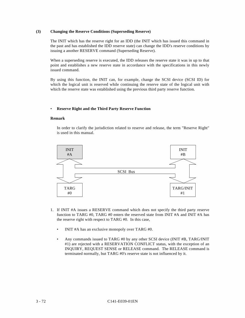
C141-E039-01EN3 - 72
(3) Changing the Reserve Conditions (Superseding Reserve)
The INIT which has the reserve right for an IDD (the INIT which has issued this command inthe past and has established the IDD reserve state) can change the IDD's reserve conditions byissuing a another RESERVE command (Superseding Reserve).
When a superseding reserve is executed, the IDD releases the reserve state it was in up to thatpoint and establishes a new reserve state in accordance with the specifications in this newlyissued command.
By using this function, the INIT can, for example, change the SCSI device (SCSI ID) forwhich the logical unit is reserved while continuing the reserve state of the logical unit withwhich the reserve state was established using the previous third party reserve function.
• Reserve Right and the Third Party Reserve Function
Remark
In order to clarify the jurisdiction related to reserve and release, the term "Reserve Right"is used in this manual.
1. If INIT #A issues a RESERVE command which does not specify the third party reservefunction to TARG #0, TARG #0 enters the reserved state from INIT #A and INIT #A hasthe reserve right with respect to TARG #0. In this case,
• INIT #A has an exclusive monopoly over TARG #0.
• Any commands issued to TARG #0 by any other SCSI device (INIT #B, TARG/INIT#1) are rejected with a RESERVATION CONFLICT status, with the exception of anINQUIRY, REQUEST SENSE or RELEASE command. The RELEASE command isterminated normally, but TARG #0's reserve state is not influenced by it.
TARG#0
INIT#A
TARG/INIT#1
SCSI Bus
INIT#B
C141-E039-01EN 3 - 73
2. If INIT #A issues a RESERVE command which specifies the third party reserve function("3rd Pty Dev ID" = TARG/INIT#1), TARG #0 becomes reserved from TARG/INIT #1,but INIT #A has the reserve right. In this case,
• TARG/INIT #1 has an exclusive monopoly of TARG #0. However, if TARG/INIT#1issues a RESERVE command, that command is rejected with a RESERVATIONCONFLICT status. Also, a RELEASE command is terminated normally, but it has noinfluence on the TARG #0 reserve right.
• INIT #A can issue INQUIRY, REQUEST SENSE, RELEASE and RESERVEcommands to TARG #0, but other commands are rejected with a RESERVATIONCONFLICT status. A RELEASE or RELEASE EXTENDED command issued byINIT #A releases TARG #0's reserved state. Also, a RESERVE or RESERVEEXTENDED command changes the reserve state of TARG #0.
• Commands issued by INIT #B to TARG #0 are rejected with a RESERVATIONCONFLICT status, except the INQUIRY, REQUEST SENSE and RELEASEcommands. A RELEASE command is terminated normally, but it has no influence onthe TARG #0 reserve right.
3. An example of the third party reserve function is applicable when using the COPYcommand. For example, TARG/INIT #1 supports the COPY command, uses the COPYcommand and in the case that a data transfer between TARG #0 and TARG/INIT#1 isexecuted, if the third party reserve in 2) is executed before INIT #A issues a COPYcommand to TARG/INIT #1, access to TARG #0 by INIT #B during execution of theCOPY command can be prohibited.
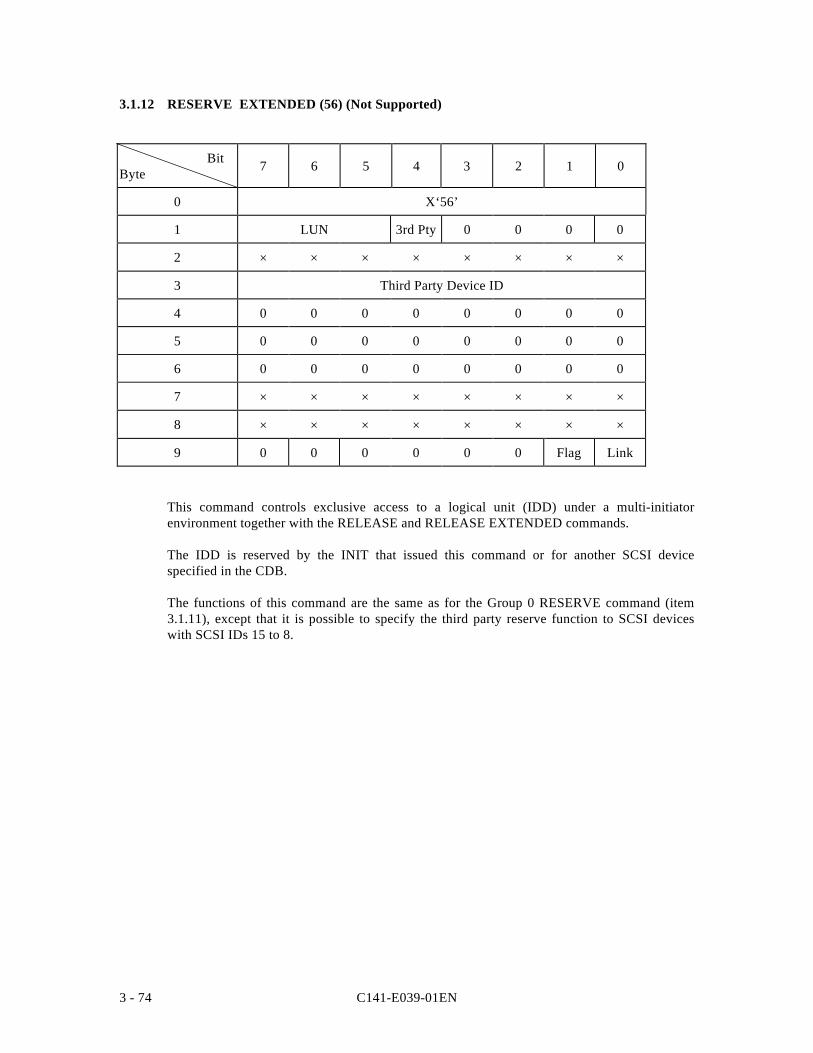
C141-E039-01EN3 - 74
3.1.12 RESERVE EXTENDED (56) (Not Supported)
BitByte 7 6 5 4 3 2 1 0
0 X‘56’
1 LUN 3rd Pty 0 0 0 0
2 × × × × × × × ×
3 Third Party Device ID
4 0 0 0 0 0 0 0 0
5 0 0 0 0 0 0 0 0
6 0 0 0 0 0 0 0 0
7 × × × × × × × ×
8 × × × × × × × ×
9 0 0 0 0 0 0 Flag Link
This command controls exclusive access to a logical unit (IDD) under a multi-initiatorenvironment together with the RELEASE and RELEASE EXTENDED commands.
The IDD is reserved by the INIT that issued this command or for another SCSI devicespecified in the CDB.
The functions of this command are the same as for the Group 0 RESERVE command (item3.1.11), except that it is possible to specify the third party reserve function to SCSI deviceswith SCSI IDs 15 to 8.
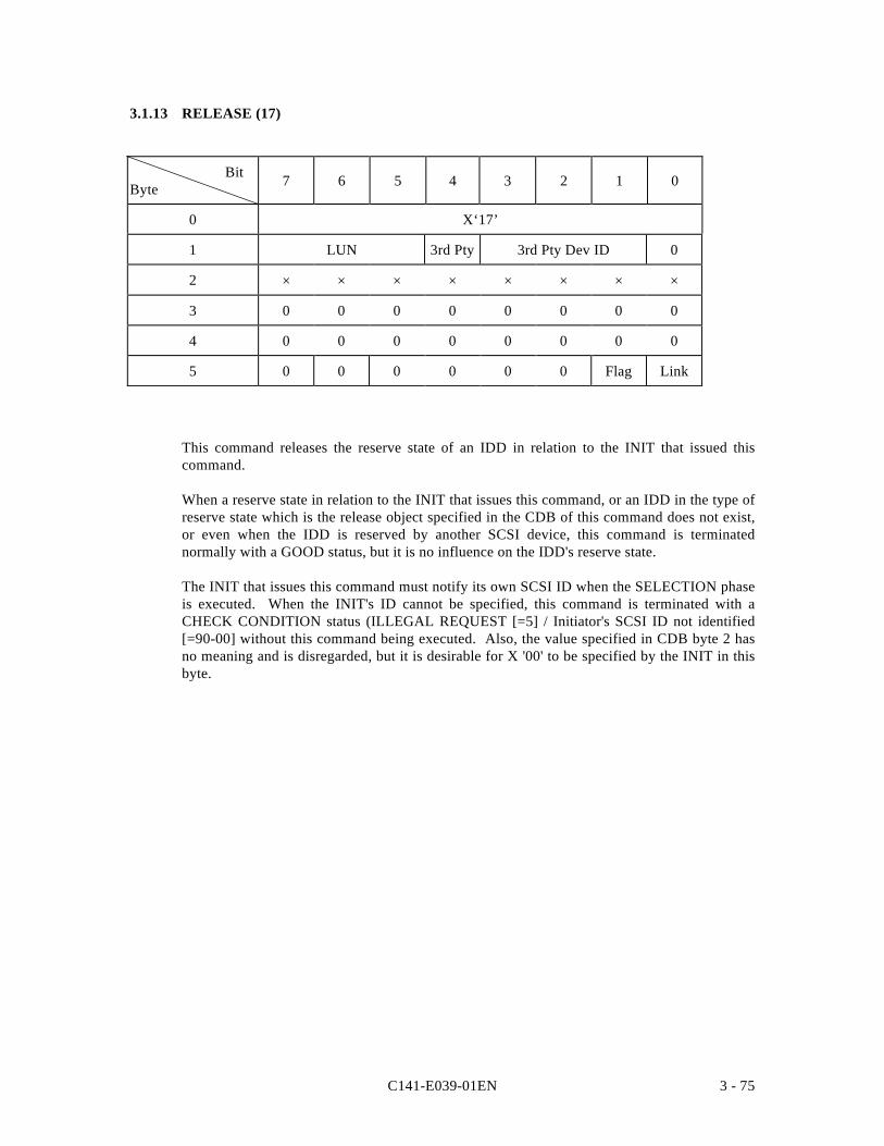
C141-E039-01EN 3 - 75
3.1.13 RELEASE (17)
BitByte 7 6 5 4 3 2 1 0
0 X‘17’
1 LUN 3rd Pty 3rd Pty Dev ID 0
2 × × × × × × × ×
3 0 0 0 0 0 0 0 0
4 0 0 0 0 0 0 0 0
5 0 0 0 0 0 0 Flag Link
This command releases the reserve state of an IDD in relation to the INIT that issued thiscommand.
When a reserve state in relation to the INIT that issues this command, or an IDD in the type ofreserve state which is the release object specified in the CDB of this command does not exist,or even when the IDD is reserved by another SCSI device, this command is terminatednormally with a GOOD status, but it is no influence on the IDD's reserve state.
The INIT that issues this command must notify its own SCSI ID when the SELECTION phaseis executed. When the INIT's ID cannot be specified, this command is terminated with aCHECK CONDITION status (ILLEGAL REQUEST [=5] / Initiator's SCSI ID not identified[=90-00] without this command being executed. Also, the value specified in CDB byte 2 hasno meaning and is disregarded, but it is desirable for X '00' to be specified by the INIT in thisbyte.
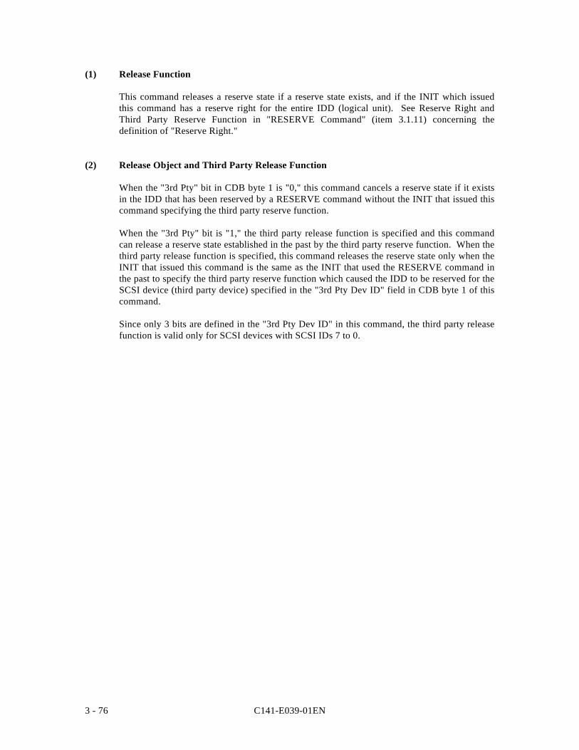
C141-E039-01EN3 - 76
(1) Release Function
This command releases a reserve state if a reserve state exists, and if the INIT which issuedthis command has a reserve right for the entire IDD (logical unit). See Reserve Right andThird Party Reserve Function in "RESERVE Command" (item 3.1.11) concerning thedefinition of "Reserve Right."
(2) Release Object and Third Party Release Function
When the "3rd Pty" bit in CDB byte 1 is "0," this command cancels a reserve state if it existsin the IDD that has been reserved by a RESERVE command without the INIT that issued thiscommand specifying the third party reserve function.
When the "3rd Pty" bit is "1," the third party release function is specified and this commandcan release a reserve state established in the past by the third party reserve function. When thethird party release function is specified, this command releases the reserve state only when theINIT that issued this command is the same as the INIT that used the RESERVE command inthe past to specify the third party reserve function which caused the IDD to be reserved for theSCSI device (third party device) specified in the "3rd Pty Dev ID" field in CDB byte 1 of thiscommand.
Since only 3 bits are defined in the "3rd Pty Dev ID" in this command, the third party releasefunction is valid only for SCSI devices with SCSI IDs 7 to 0.
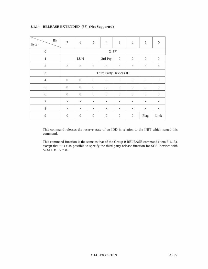
C141-E039-01EN 3 - 77
3.1.14 RELEASE EXTENDED (57) (Not Supported)
BitByte 7 6 5 4 3 2 1 0
0 X‘57’
1 LUN 3rd Pty 0 0 0 0
2 × × × × × × × ×
3 Third Party Devices ID
4 0 0 0 0 0 0 0 0
5 0 0 0 0 0 0 0 0
6 0 0 0 0 0 0 0 0
7 × × × × × × × ×
8 × × × × × × × ×
9 0 0 0 0 0 0 Flag Link
This command releases the reserve state of an IDD in relation to the INIT which issued thiscommand.
This command function is the same as that of the Group 0 RELEASE command (item 3.1.13),except that it is also possible to specify the third party release function for SCSI devices withSCSI IDs 15 to 8.
C141-E039-01EN3 - 78
3.1.15 REQUEST SENSE (03)
BitByte 7 6 5 4 3 2 1 0
0 X‘03’
1 LUN 0 0 0 0 0
2 0 0 0 0 0 0 0 0
3 0 0 0 0 0 0 0 0
4 Transfer Byte Length
5 0 0 0 0 0 0 Flag Link
This command transfers sense data to the INIT. This command is executed immediatelywithout queueing in a system which issues only commands with no tags or links.
The length of the sense data in the IDD is 48 bytes. The "Transfer byte length" field in theCDB indicates the number of bytes of sense data which can be received by the INIT. The IDDtransfers sense data to the INIT by either of the following two methods, depending on thespecification in the CHANGE DEFINITION command (SCSI level). Furthermore, see item3.1.4 (SCSI Level) concerning the CHANGE DEFINITION command.
• If the SCSI-2 mode is specified in the CHANGE DEFINITION command, the IDDtransfers the number of bytes of sense data specified in the "Transfer byte length"field or the number of bytes in the sense data held by the IDD (48 bytes), whichever issmaller, to the INIT. When zero is specified in the "Transfer byte length" field, thiscommand is terminated with nothing transferred, but in this cases also, the sense dataheld by the IDD are cleared.
• If SCSI-1/CCS Mode is specified in the CHANGE DEFINITION command, whenzero is specified in the "Transfer byte length" field, the IDD transfers to the INIT only4 bytes of sense data, from the top. When a value other than zero is specified in the"Transfer byte length" field, the IDD transfers to the INIT the number of bytes ofsense data specified in the "Transfer byte length" field or the length of sense data heldby the IDD (48 bytes), whichever is smaller.
As described in 1.6 "Sense Data Hold State," if the IDD terminates a command which it iscurrently executing abnormally, it generates sense data for the INIT that issued that commandand maintains those sense data in the hold state.
Sense data are held in a valid state until they are read by a REQUEST SENSE command fromthe INIT for which they are held. However, sense data which are being held are cleared by anABORT message from the INIT for which they are held, a BUS DEVICE RESET message orCLEAR QUEUE MESSAGE from any INIT, or a RESET condition.
If a command is terminated with a CHECK CONDITION status, when the SCSI bus enters the BUSFREE phase unintentionally during execution of a command, or when the INIT detects that there isno reconnection request from the IDD, the INIT should issue this command and fetch the sense data.
C141-E039-01EN 3 - 79
Note:
See Section 1.6, "Sense Data Hold State" concerning details of the sense data hold stateand see Section 4.1, "Sense Data" concerning the format of sense data transferred by thiscommand from the IDD to the INIT, and its contents.
If this command is issued while the IDD is holding the UNIT ATTENTION condition, if theIDD is not in the sense data hold state at that point, sense data indicating the UNITATTENTION condition are sent to the INIT by this command and the UNIT ATTENTIONcondition is cleared. For details, see Section 1.5, "UNIT ATTENTION Condition."
If this command is issued when valid sense data are not being held, the IDD sends the sensekey "NO SENSE" [=0] with sense data showing the message "No additional sense information[=00-00]" to the INIT.
This command is terminated abnormally with a CHECK CONDITION status reported onlywhen the conditions shown below are detected. In this case, new sense data are generated andthe sense data which had been held up to that point are lost.
• An error in a specification other than the LUN field of the CDB• Sense data cannot be sent due to a hardware error in the IDD• An unrecoverable error is detected on the SCSI bus.• A state appropriate to an overlapping command exception condition (see item 1.7.1).
In cases other than the above, the sense data currently being held, or, when there are no sensedata being held, the sense data which indicate the state if an error occurred during execution ofthis command, are sent to the INIT and it is terminated with a GOOD status. However, if anerror which has been recovered from by retry processing is detected during execution of thiscommand, and if the mode which reports "RECOVERED ERROR" is specified, this commandis terminated with a CHECK CONDITION status after sense data are sent to the INIT andsense data (RECOVERED ERROR [=1]) which indicate the contents of that error are newlygenerated.
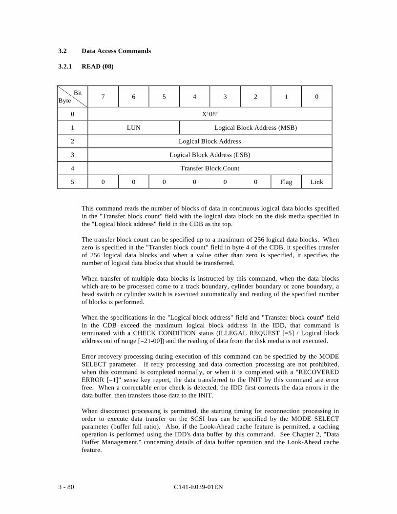
C141-E039-01EN3 - 80
3.2 Data Access Commands
3.2.1 READ (08)
BitByte 7 6 5 4 3 2 1 0
0 X‘08’
1 LUN Logical Block Address (MSB)
2 Logical Block Address
3 Logical Block Address (LSB)
4 Transfer Block Count
5 0 0 0 0 0 0 Flag Link
This command reads the number of blocks of data in continuous logical data blocks specifiedin the "Transfer block count" field with the logical data block on the disk media specified inthe "Logical block address" field in the CDB as the top.
The transfer block count can be specified up to a maximum of 256 logical data blocks. Whenzero is specified in the "Transfer block count" field in byte 4 of the CDB, it specifies transferof 256 logical data blocks and when a value other than zero is specified, it specifies thenumber of logical data blocks that should be transferred.
When transfer of multiple data blocks is instructed by this command, when the data blockswhich are to be processed come to a track boundary, cylinder boundary or zone boundary, ahead switch or cylinder switch is executed automatically and reading of the specified numberof blocks is performed.
When the specifications in the "Logical block address" field and "Transfer block count" fieldin the CDB exceed the maximum logical block address in the IDD, that command isterminated with a CHECK CONDITION status (ILLEGAL REQUEST [=5] / Logical blockaddress out of range [=21-00]) and the reading of data from the disk media is not executed.
Error recovery processing during execution of this command can be specified by the MODESELECT parameter. If retry processing and data correction processing are not prohibited,when this command is completed normally, or when it is completed with a "RECOVEREDERROR [=1]" sense key report, the data transferred to the INIT by this command are errorfree. When a correctable error check is detected, the IDD first corrects the data errors in thedata buffer, then transfers those data to the INIT.
When disconnect processing is permitted, the starting timing for reconnection processing inorder to execute data transfer on the SCSI bus can be specified by the MODE SELECTparameter (buffer full ratio). Also, if the Look-Ahead cache feature is permitted, a cachingoperation is performed using the IDD's data buffer by this command. See Chapter 2, "DataBuffer Management," concerning details of data buffer operation and the Look-Ahead cachefeature.
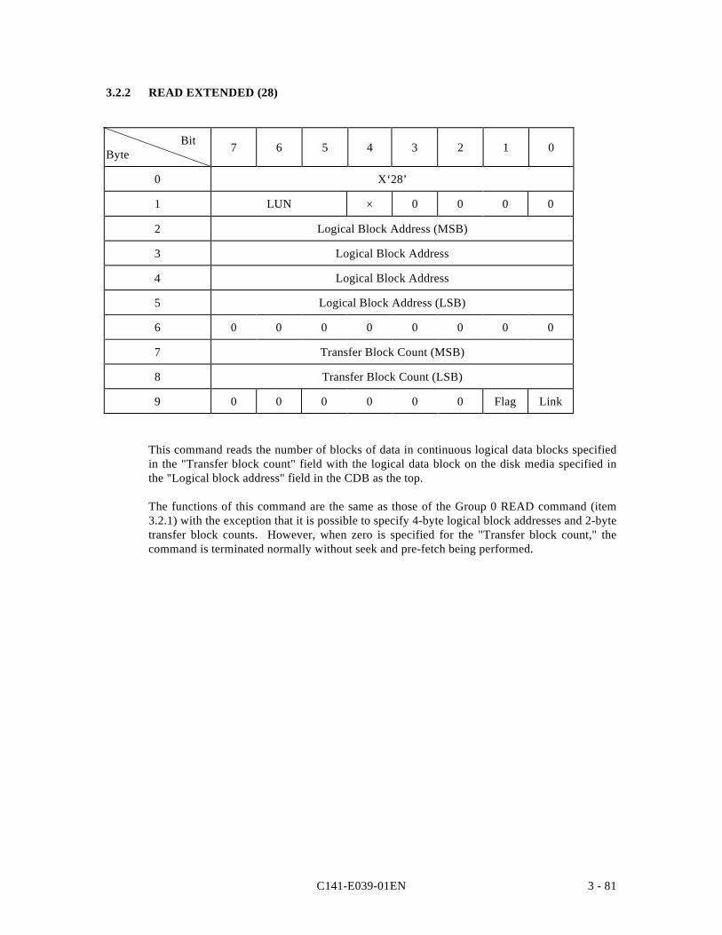
C141-E039-01EN 3 - 81
3.2.2 READ EXTENDED (28)
BitByte 7 6 5 4 3 2 1 0
0 X‘28’
1 LUN × 0 0 0 0
2 Logical Block Address (MSB)
3 Logical Block Address
4 Logical Block Address
5 Logical Block Address (LSB)
6 0 0 0 0 0 0 0 0
7 Transfer Block Count (MSB)
8 Transfer Block Count (LSB)
9 0 0 0 0 0 0 Flag Link
This command reads the number of blocks of data in continuous logical data blocks specifiedin the "Transfer block count" field with the logical data block on the disk media specified inthe "Logical block address" field in the CDB as the top.
The functions of this command are the same as those of the Group 0 READ command (item3.2.1) with the exception that it is possible to specify 4-byte logical block addresses and 2-bytetransfer block counts. However, when zero is specified for the "Transfer block count," thecommand is terminated normally without seek and pre-fetch being performed.
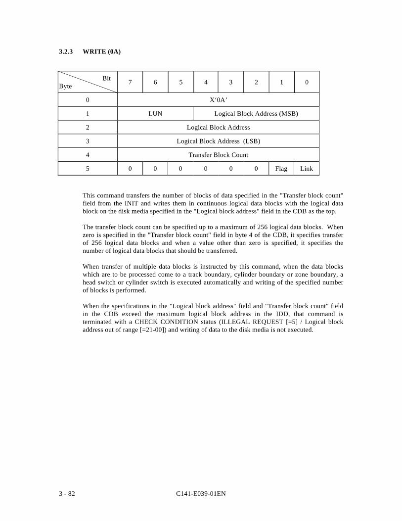
C141-E039-01EN3 - 82
3.2.3 WRITE (0A)
BitByte 7 6 5 4 3 2 1 0
0 X‘0A’
1 LUN Logical Block Address (MSB)
2 Logical Block Address
3 Logical Block Address (LSB)
4 Transfer Block Count
5 0 0 0 0 0 0 Flag Link
This command transfers the number of blocks of data specified in the "Transfer block count"field from the INIT and writes them in continuous logical data blocks with the logical datablock on the disk media specified in the "Logical block address" field in the CDB as the top.
The transfer block count can be specified up to a maximum of 256 logical data blocks. Whenzero is specified in the "Transfer block count" field in byte 4 of the CDB, it specifies transferof 256 logical data blocks and when a value other than zero is specified, it specifies thenumber of logical data blocks that should be transferred.
When transfer of multiple data blocks is instructed by this command, when the data blockswhich are to be processed come to a track boundary, cylinder boundary or zone boundary, ahead switch or cylinder switch is executed automatically and writing of the specified numberof blocks is performed.
When the specifications in the "Logical block address" field and "Transfer block count" fieldin the CDB exceed the maximum logical block address in the IDD, that command isterminated with a CHECK CONDITION status (ILLEGAL REQUEST [=5] / Logical blockaddress out of range [=21-00]) and writing of data to the disk media is not executed.
C141-E039-01EN 3 - 83
The IDD does not perform data transfer immediately after receiving the CDB, but afterperforming automatic disconnect processing once, it executes pre-fetching of data. Ifdisconnect processing is permitted, the IDD either completes transfer of all the data specifiedin the command or, at the point when the empty space in the data buffer runs out, disconnectprocessing is executed. Positioning of the specified data blocks is performed in parallel withthis data transfer, and writing of data from the data buffer to the disk media is executedimmediately after positioning is completed. See Section 2.1 "Data Buffer" for details of databuffer operation and control of the timing for starting reconnection processing by the MODESELECT parameter (buffer empty ratio).
If the write cache function is enabled, the IDD reports a status byte at the point when receptionof all the data transferred from the INIT is completed. If an error occurs while data are beingwritten to the disk media, a CHECK CONDITION status is reported for the command to beexecuted next. If the write cache function is disabled, a status byte is reported after writing tothe disk media of all the data transferred from the INIT is completed, then execution of thecommand is terminated.
Note:
Even when there is an error in the specification in the CDB, or when a write operation tothe disk media cannot be executed normally due to various other causes, the transfer ofdata (data is pre-fetched to the data buffer) from the INIT to the IDD may be executed. Inthis case, the length of data transferred from the INIT to the IDD is undefined. Also, allthe data transferred to the IDD will not necessarily be actually written to the disk media.However, if the command is terminated with a CHECK CONDITION status and the sensekey of the sense data indicates "ILLEGAL REQUEST [=5]," the data from that commandis not written to the disk media by a write operation.
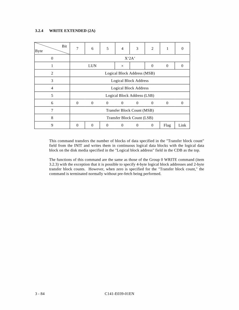
C141-E039-01EN3 - 84
3.2.4 WRITE EXTENDED (2A)
BitByte 7 6 5 4 3 2 1 0
0 X‘2A’
1 LUN × 0 0 0
2 Logical Block Address (MSB)
3 Logical Block Address
4 Logical Block Address
5 Logical Block Address (LSB)
6 0 0 0 0 0 0 0 0
7 Transfer Block Count (MSB)
8 Transfer Block Count (LSB)
9 0 0 0 0 0 0 Flag Link
This command transfers the number of blocks of data specified in the "Transfer block count"field from the INIT and writes them in continuous logical data blocks with the logical datablock on the disk media specified in the "Logical block address" field in the CDB as the top.
The functions of this command are the same as those of the Group 0 WRITE command (item3.2.3) with the exception that it is possible to specify 4-byte logical block addresses and 2-bytetransfer block counts. However, when zero is specified for the "Transfer block count," thecommand is terminated normally without pre-fetch being performed.
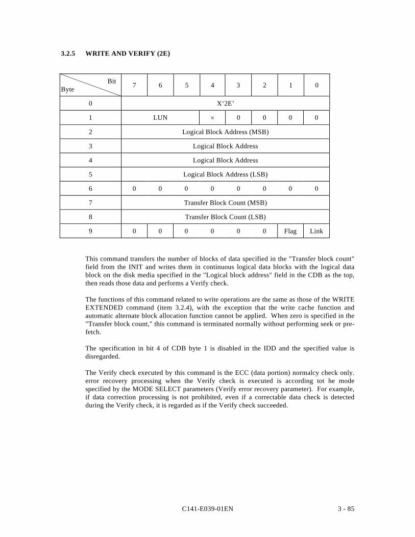
C141-E039-01EN 3 - 85
3.2.5 WRITE AND VERIFY (2E)
BitByte 7 6 5 4 3 2 1 0
0 X‘2E’
1 LUN × 0 0 0 0
2 Logical Block Address (MSB)
3 Logical Block Address
4 Logical Block Address
5 Logical Block Address (LSB)
6 0 0 0 0 0 0 0 0
7 Transfer Block Count (MSB)
8 Transfer Block Count (LSB)
9 0 0 0 0 0 0 Flag Link
This command transfers the number of blocks of data specified in the "Transfer block count"field from the INIT and writes them in continuous logical data blocks with the logical datablock on the disk media specified in the "Logical block address" field in the CDB as the top,then reads those data and performs a Verify check.
The functions of this command related to write operations are the same as those of the WRITEEXTENDED command (item 3.2.4), with the exception that the write cache function andautomatic alternate block allocation function cannot be applied. When zero is specified in the"Transfer block count," this command is terminated normally without performing seek or pre-fetch.
The specification in bit 4 of CDB byte 1 is disabled in the IDD and the specified value isdisregarded.
The Verify check executed by this command is the ECC (data portion) normalcy check only.error recovery processing when the Verify check is executed is according tot he modespecified by the MODE SELECT parameters (Verify error recovery parameter). For example,if data correction processing is not prohibited, even if a correctable data check is detectedduring the Verify check, it is regarded as if the Verify check succeeded.
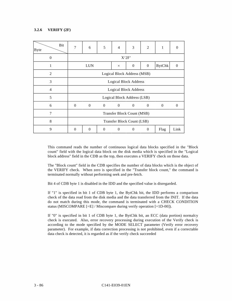
C141-E039-01EN3 - 86
3.2.6 VERIFY (2F)
BitByte 7 6 5 4 3 2 1 0
0 X‘2F’
1 LUN × 0 0 BytChk 0
2 Logical Block Address (MSB)
3 Logical Block Address
4 Logical Block Address
5 Logical Block Address (LSB)
6 0 0 0 0 0 0 0 0
7 Transfer Block Count (MSB)
8 Transfer Block Count (LSB)
9 0 0 0 0 0 0 Flag Link
This command reads the number of continuous logical data blocks specified in the "Blockcount" field with the logical data block on the disk media which is specified in the "Logicalblock address" field in the CDB as the top, then executes a VERIFY check on those data.
The "Block count" field in the CDB specifies the number of data blocks which is the object ofthe VERIFY check. When zero is specified in the "Transfer block count," the command isterminated normally without performing seek and pre-fetch.
Bit 4 of CDB byte 1 is disabled in the IDD and the specified value is disregarded.
If "1" is specified in bit 1 of CDB byte 1, the BytChk bit, the IDD performs a comparisoncheck of the data read from the disk media and the data transferred from the INIT. If the datado not match during this mode, the command is terminated with a CHECK CONDITIONstatus (MISCOMPARE [=E] / Miscompare during verify operation [=1D-00]).
If "0" is specified in bit 1 of CDB byte 1, the BytChk bit, an ECC (data portion) normalcycheck is executed. Also, error recovery processing during execution of the Verify check isaccording to the mode specified by the MODE SELECT parameter (Verify error recoveryparameter). For example, if data correction processing is not prohibited, even if a correctabledata check is detected, it is regarded as if the verify check succeeded
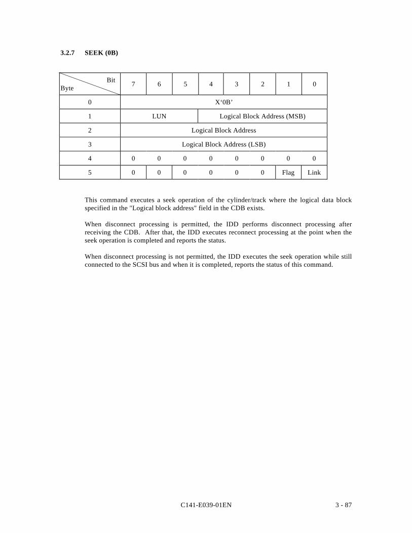
C141-E039-01EN 3 - 87
3.2.7 SEEK (0B)
BitByte 7 6 5 4 3 2 1 0
0 X‘0B’
1 LUN Logical Block Address (MSB)
2 Logical Block Address
3 Logical Block Address (LSB)
4 0 0 0 0 0 0 0 0
5 0 0 0 0 0 0 Flag Link
This command executes a seek operation of the cylinder/track where the logical data blockspecified in the "Logical block address" field in the CDB exists.
When disconnect processing is permitted, the IDD performs disconnect processing afterreceiving the CDB. After that, the IDD executes reconnect processing at the point when theseek operation is completed and reports the status.
When disconnect processing is not permitted, the IDD executes the seek operation while stillconnected to the SCSI bus and when it is completed, reports the status of this command.
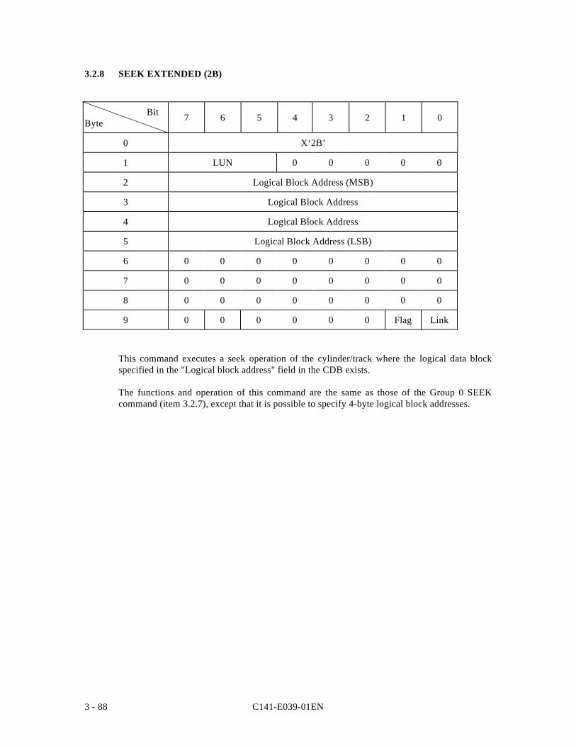
C141-E039-01EN3 - 88
3.2.8 SEEK EXTENDED (2B)
BitByte 7 6 5 4 3 2 1 0
0 X‘2B’
1 LUN 0 0 0 0 0
2 Logical Block Address (MSB)
3 Logical Block Address
4 Logical Block Address
5 Logical Block Address (LSB)
6 0 0 0 0 0 0 0 0
7 0 0 0 0 0 0 0 0
8 0 0 0 0 0 0 0 0
9 0 0 0 0 0 0 Flag Link
This command executes a seek operation of the cylinder/track where the logical data blockspecified in the "Logical block address" field in the CDB exists.
The functions and operation of this command are the same as those of the Group 0 SEEKcommand (item 3.2.7), except that it is possible to specify 4-byte logical block addresses.
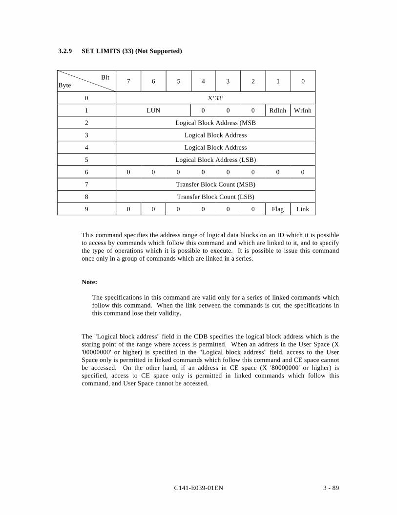
C141-E039-01EN 3 - 89
3.2.9 SET LIMITS (33) (Not Supported)
BitByte 7 6 5 4 3 2 1 0
0 X‘33’
1 LUN 0 0 0 RdInh WrInh
2 Logical Block Address (MSB
3 Logical Block Address
4 Logical Block Address
5 Logical Block Address (LSB)
6 0 0 0 0 0 0 0 0
7 Transfer Block Count (MSB)
8 Transfer Block Count (LSB)
9 0 0 0 0 0 0 Flag Link
This command specifies the address range of logical data blocks on an ID which it is possibleto access by commands which follow this command and which are linked to it, and to specifythe type of operations which it is possible to execute. It is possible to issue this commandonce only in a group of commands which are linked in a series.
Note:
The specifications in this command are valid only for a series of linked commands whichfollow this command. When the link between the commands is cut, the specifications inthis command lose their validity.
The "Logical block address" field in the CDB specifies the logical block address which is thestaring point of the range where access is permitted. When an address in the User Space (X'00000000' or higher) is specified in the "Logical block address" field, access to the UserSpace only is permitted in linked commands which follow this command and CE space cannotbe accessed. On the other hand, if an address in CE space (X '80000000' or higher) isspecified, access to CE space only is permitted in linked commands which follow thiscommand, and User Space cannot be accessed.
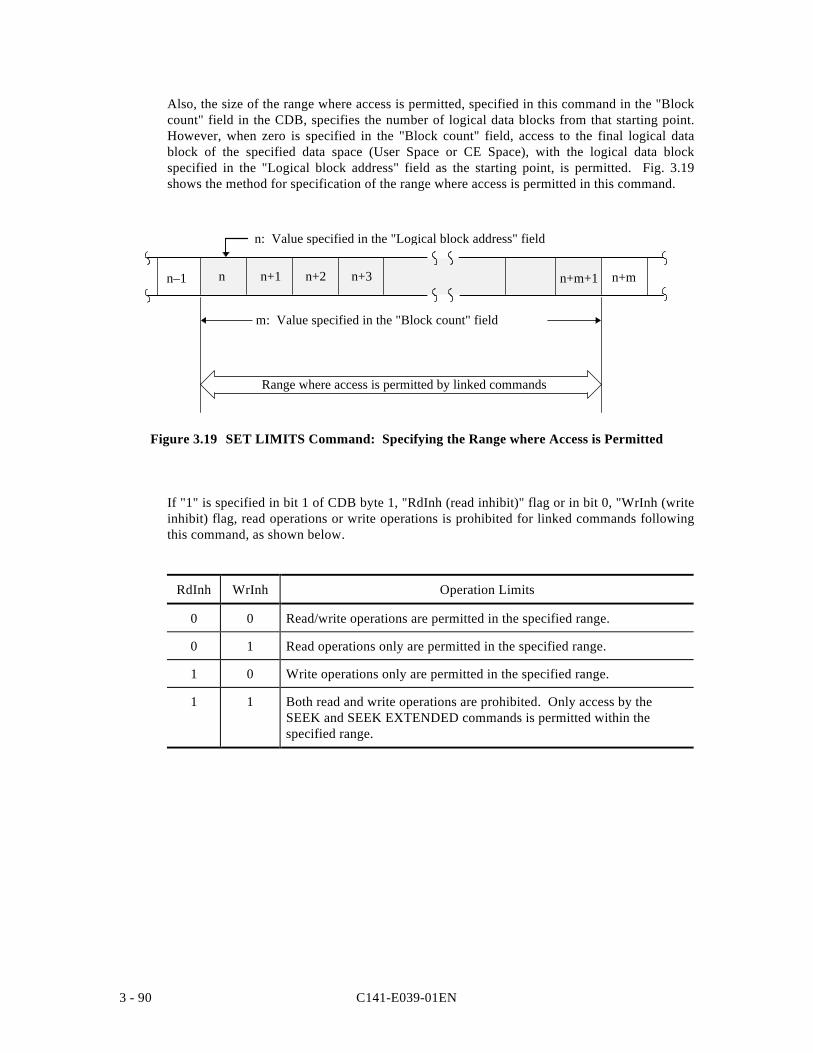
C141-E039-01EN3 - 90
Also, the size of the range where access is permitted, specified in this command in the "Blockcount" field in the CDB, specifies the number of logical data blocks from that starting point.However, when zero is specified in the "Block count" field, access to the final logical datablock of the specified data space (User Space or CE Space), with the logical data blockspecified in the "Logical block address" field as the starting point, is permitted. Fig. 3.19shows the method for specification of the range where access is permitted in this command.
n+mn–1 n+m+1
m: Value specified in the "Block count" field
Range where access is permitted by linked commands
n n+3n+2n+1
n: Value specified in the "Logical block address" field
Figure 3.19 SET LIMITS Command: Specifying the Range where Access is Permitted
If "1" is specified in bit 1 of CDB byte 1, "RdInh (read inhibit)" flag or in bit 0, "WrInh (writeinhibit) flag, read operations or write operations is prohibited for linked commands followingthis command, as shown below.
RdInh WrInh Operation Limits
0 0 Read/write operations are permitted in the specified range.
0 1 Read operations only are permitted in the specified range.
1 0 Write operations only are permitted in the specified range.
1 1 Both read and write operations are prohibited. Only access by theSEEK and SEEK EXTENDED commands is permitted within thespecified range.
C141-E039-01EN 3 - 91
When access to logical data blocks outside the address range defined by this command bylinked commands which follow this command is specified, or when a prohibited type of accessoperation is specified, that command is terminated with a CHECK CONDITION statuswithout being executed. (When there is a violation of the (DATA PROTECT [=7] / Writeprotect [=27-00]: "WrInh" flag, or when there is a violation of the (DATA PROTECT [=7] /No additional sense information [=00-00]: "RdInh" flag.) When this command is issued againin a group of commands linked in a series, the 2nd SET LIMITS command is rejected and aCHECK CONDITION status (DATA PROTECT [=7] / Command sequence error [=2C-00]) isreported.
Notes:
1. Commands which come under restrictions in read operations or write operations when"1" is specified in the "RdInh" (read inhibit) or "WrInh" (write inhibit) flag are asfollows.
“RdInh” • READ • VERIFY (*)• READ EXTENDED (*) • WRITE AND VERIFY (*)• READ LONG • PRE-FETCH
“WrInh” • FORMAT UNIT • WRITE EXTENDED (*)• REASSIGN BLOCKS • WRITE LONG• WRITE • WRITE SAME• WRITE AND VERIFY (*)
* When zero is specified in the processing block count that command is notexecuted.
2. Even if a write operation is prohibited by this command, "0" is indicated in the "WP(write protect)" bit reported to the INIT in the MODE SENSE and MODE SENSEEXTENDED commands.
3. If "0" is specified in this command in the "WrInh" flag, execution of a FORMATUNIT command or REASSIGN BLOCKS command issued in linked form followingthis command is permitted (the specification of the range where access is permitted isnot applied.)
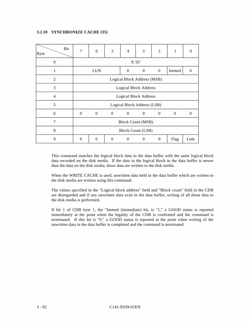
C141-E039-01EN3 - 92
3.2.10 SYNCHRONIZE CACHE (35)
BitByte 7 6 5 4 3 2 1 0
0 X‘35’
1 LUN 0 0 0 Immed 0
2 Logical Block Address (MSB)
3 Logical Block Address
4 Logical Block Address
5 Logical Block Address (LSB)
6 0 0 0 0 0 0 0 0
7 Block Count (MSB)
8 Block Count (LSB)
9 0 0 0 0 0 0 Flag Link
This command matches the logical block data in the data buffer with the same logical blockdata recorded on the disk media. If the data in the logical block in the data buffer is newerthan the data on the disk media, those data are written to the disk media.
When the WRITE CACHE is used, unwritten data held in the data buffer which are written tothe disk media are written using this command.
The values specified in the "Logical block address" field and "Block count" field in the CDBare disregarded and if any unwritten data exist in the data buffer, writing of all those data tothe disk media is performed.
If bit 1 of CDB byte 1, the "Immed (immediate) bit, is "1," a GOOD status is reportedimmediately at the point when the legality of the CDB is confirmed and the command isterminated. If this bit is "0," a GOOD status is reported at the point when writing of theunwritten data in the data buffer is completed and the command is terminated.
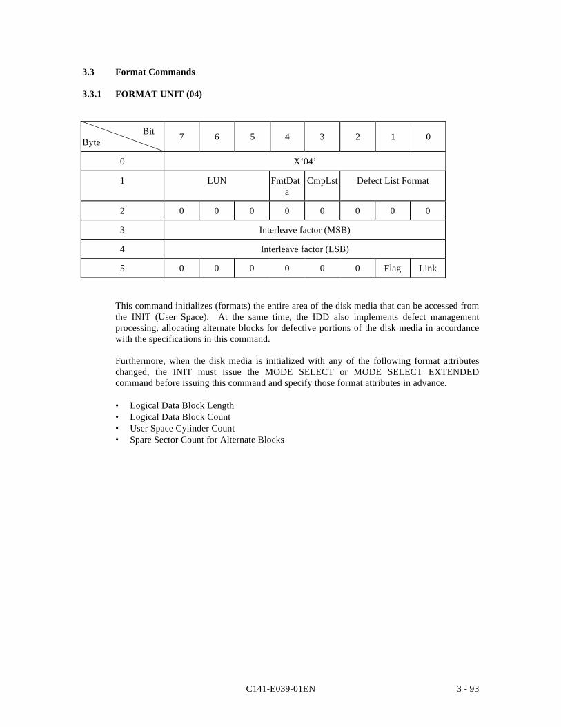
C141-E039-01EN 3 - 93
3.3 Format Commands
3.3.1 FORMAT UNIT (04)
BitByte 7 6 5 4 3 2 1 0
0 X‘04’
1 LUN FmtData
CmpLst Defect List Format
2 0 0 0 0 0 0 0 0
3 Interleave factor (MSB)
4 Interleave factor (LSB)
5 0 0 0 0 0 0 Flag Link
This command initializes (formats) the entire area of the disk media that can be accessed fromthe INIT (User Space). At the same time, the IDD also implements defect managementprocessing, allocating alternate blocks for defective portions of the disk media in accordancewith the specifications in this command.
Furthermore, when the disk media is initialized with any of the following format attributeschanged, the INIT must issue the MODE SELECT or MODE SELECT EXTENDEDcommand before issuing this command and specify those format attributes in advance.
• Logical Data Block Length• Logical Data Block Count• User Space Cylinder Count• Spare Sector Count for Alternate Blocks
C141-E039-01EN3 - 94
(1) Defect List
In order to register or specify the positions of defects on the disk media in connection withdefect management processing that can be specified from the INIT, the following types of“Defect List” are defined.
a. P List: Primary Defect List
Defect position information (permanent defects) is registered in this list at the time the diskdrive is shipped from the factory. The P List registers areas on the disk media whichclearly cannot be accessed from the INIT. The INIT can refer to the contents of this list bythe READ DEFECT DATA command only, but cannot change or erase it.
b. D List: Data Defect List
The defect information in this list is defect position information transferred from the INITwhen this command is executed. The IDD registers this defect information on the diskmedia as the G List.
c. C List: Target Certification List
This defect list contains position information on defective data blocks detected in the datablock verify operation (Certification) after initialization when the FORMAT UNITcommand is executed. The IDD generates this list internally when the FORMAT UNITcommand is executed and adds it to the G List.
d. G List: Grown Defect List
The defect information in this list contains defect position information specified by theNIT and position information on defective data blocks detected by the IDD itself. The PList is not included in this defect list. The IDD stores the G List in an area on the diskmedia which clearly cannot be accessed from the INIT. The INIT can refer to the contentsof this list by the READ DEFECT DATA command. the following defect positioninformation is included in the G List.
• Defect information transferred from the INIT as the D List.
• Defect information detected in the Verify operation when this command was executed(C List)
• Defect information specified from the INIT by the REASSIGN BLOCKS command.
• Defect information on data blocks where alternate block allocation was performedamong defective data blocks detected by the IDD when automatic allocationprocessing of alternate blocks is permitted.
C141-E039-01EN 3 - 95
(2) Specifying the Initialization Method
The INIT can specify the method of defect processing executed by this command in the“FmtData (format data)” bit and “CmpLst (complete list)” bit of CDB byte 1 and the “DefectList Format” field.
When “1” is specified in the “FmtData (format data) bit, it indicates that the format parameters(header and defect list), described later, are transferred from the INIT when this command isexecuted. When this bit’s specification is “0,” it indicates that the format parameters are nottransferred.
When the “CmpLst (complete list)” bit is “1”, it indicates that the previously existing G List isreplaced with the defect list (D List) transferred from the INIT when this command isexecuted. When this bit is “0,” the contents of the D List are added to those of the previouslyexisting G List.
The “Defect List Forma” field specifies the format of the defect list (D List) transferred fromthe INIT when the “FmtData (format data)” bit is “1.” Any one of the following formats canbe specified for the defect list.
Defect List Format D List Format
0 0 0 Block Address Format
1 0 0 Byte Distance from the Index Format
1 0 1 Physical Sector Address Format
If (0,0,0) is specified in the Defect List Format field and a value other than 0 is specified in“Defect List Length” in the Format parameters, this command is terminated with a CHECKCONDITION status (ILLEGAL REQUEST / Invalid field in parameter list).
The “Interleave factor” field in the CDB specifies the method of positioning logical datablocks in physical sectors on the disk media. Whichever value is specified in this field, theIDD does not apply sector interleave, but physically positions logical data blocks continuouslyin continuous sectors.
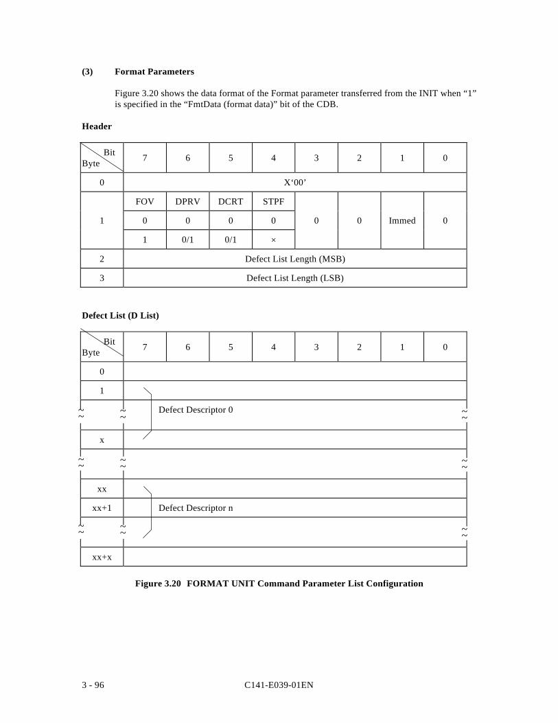
C141-E039-01EN3 - 96
(3) Format Parameters
Figure 3.20 shows the data format of the Format parameter transferred from the INIT when “1”is specified in the “FmtData (format data)” bit of the CDB.
Header
BitByte 7 6 5 4 3 2 1 0
0 X‘00’
FOV DPRV DCRT STPF
1 0 0 0 0 0 0 Immed 0
1 0/1 0/1 ×
2 Defect List Length (MSB)
3 Defect List Length (LSB)
Defect List (D List)
BitByte 7 6 5 4 3 2 1 0
0
1
Defect Descriptor 0
x
xx
xx+1 Defect Descriptor n
xx+x
Figure 3.20 FORMAT UNIT Command Parameter List Configuration
~~
~~~~ ~~
~~
~~ ~~
~~ ~~
C141-E039-01EN 3 - 97
a. Header
The top of the format parameter transferred from the INIT is a 4-byte header. The INITcan specify the method used for defect processing that is executed by this command bycontrol flags within the header.
• FOV (format option valid)
0: Indicates that the INIT does not specially specify concerning the functionsspecified by the control flags in bits 6 to 4 of byte 1 (see items b. to d.). The IDDexecutes format processing in accordance with the default values of the variouscontrol flags. If the INIT specifies “0” in this bit, “0” must be specified in all thecontrol flags in bits 6 to 4 of byte 1.
1: Indicates that the INIT is clearly specifying the functions specified by the controlflags in bits 6 to 4 of byte 1 (see items b. to d.). The IDD executes formatprocessing according to the values specified in the various control flags.
• DPRY (disable primary): Default value: “0”
0: Specifies execution of format processing using the P List. Alternate blocks areallocated as substitutes for sectors in which defects registered in the P List exist,and logical data blocks are not positioned there.
1: Specifies use of the P List in defect processing. Even if this value is specified,the P List itself is saved without being erased.
Note:
When the disk media is being initialized for normal operation, the P List must byall means be used. Therefore, “0” should be specified in this bit.
• DCRT (disable certification): Default value: “0”
0: Specifies that data block verification be performed after initialization of the diskmedia. The IDD confirms that all logical data blocks can be read from normallyafter initialization is completed. Any defective data blocks detected in this verifyoperation are registered as a C List and alternate blocks are allocated for thosedata blocks.
1: Indicates that data block verify operations are prohibited after initialization of thedisk media.
C141-E039-01EN3 - 98
• STPF (stop format): Default value: “1”
When the defect list (P List or G List) necessary for executing the defect processingspecified in this command, cannot be read from the disk media, this bit indicateswhether to continue (“0” is specified) or terminate (“1” is specified) commandprocessing, but in the IDD, this bit’s specification is disabled, and the specified valueis disregarded. When the necessary defect list cannot be read, this command isterminated with a CHECK CONDITION status. The sense data at this time indicate“MEDIUM ERROR [=3] / Primary defect list not found [=1C-01]” or “MEDIUMERROR [=3] / Defect list error in primary list [=19-02],” if the P List cannot be readand “MEDIUM ERROR [=3] / Grown defect list not found [=1C-02]” or “MEDIUMERROR [=3] / Defect list error in grown list [=19-03],” if the G List cannot be read.
• Immed (Immediate)
“1” : If “1” is specified in the Immed (immediate) bit, at the point when the CDB’slegality is confirmed, or at the point when transfer of the defect list iscompleted, a “GOOD” status is reported.
“0” : If “0” is specified in the Immed (immediate) bit, the specified operation isexecuted and the status byte is reported at the point when that operation iscompleted, then the command is terminated.
• Defect List Length
This field specifies the total number of bytes in the “Defect list” transferred from theINIT following the header. The byte length of the “Defect descriptor” whichconfigures the defect list differs depending on its format and the value specified bythis field must be a multiple of 4 when the defect descriptor is in the block addressformat, and must be a multiple of 8 when the defect descriptor is in the byte distancefrom the index format or the physical sector address format. When zero is specifiedin this field, it indicates that the defect list is not transferred.
Note:
The disk media defect processing method implemented during FORMAT UNITcommand execution is specified by the CDB and by header of the formatparameters transferred from the INIT. By specifying zero in the “Defect listlength” field in the Format parameter header, the INIT can specify the controlflags related to formatting processing without transferring the defect list (D List).
b. Defect List (D List)
The defect list (D List) contains defect position information about the disk media specifiedby the INIT and is configured from one or more “Defect descriptors.” “Defect descriptorsmust be described in the format specified in the “Defect List Format” field of the CDB.
The configurations which it is possible to specify for the “Defect descriptors” in the defectlist (D List), and their description formats, are shown below. Furthermore, it is possibleonly to specify User Space and CE Space address information on the disk media in theDefect list (D List).
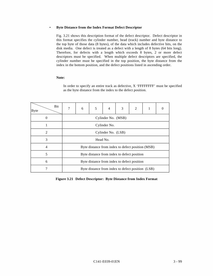
C141-E039-01EN 3 - 99
• Byte Distance from the Index Format Defect Descriptor
Fig. 3.21 shows this description format of the defect descriptor. Defect descriptor inthis format specifies the cylinder number, head (track) number and byte distance tothe top byte of those data (8 bytes), of the data which includes defective bits, on thedisk media. One defect is treated as a defect with a length of 8 bytes (64 bits long).Therefore, for defects with a length which exceeds 8 bytes, 2 or more defectdescriptors must be specified. When multiple defect descriptors are specified, thecylinder number must be specified in the top position, the byte distance from theindex in the bottom position, and the defect positions listed in ascending order.
Note:
In order to specify an entire track as defective, X ‘FFFFFFFF’ must be specifiedas the byte distance from the index to the defect position.
BitByte 7 6 5 4 3 2 1 0
0 Cylinder No. (MSB)
1 Cylinder No.
2 Cylinder No. (LSB)
3 Head No.
4 Byte distance from index to defect position (MSB)
5 Byte distance from index to defect position
6 Byte distance from index to defect position
7 Byte distance from index to defect position (LSB)
Figure 3.21 Defect Descriptor: Byte Distance from Index Format
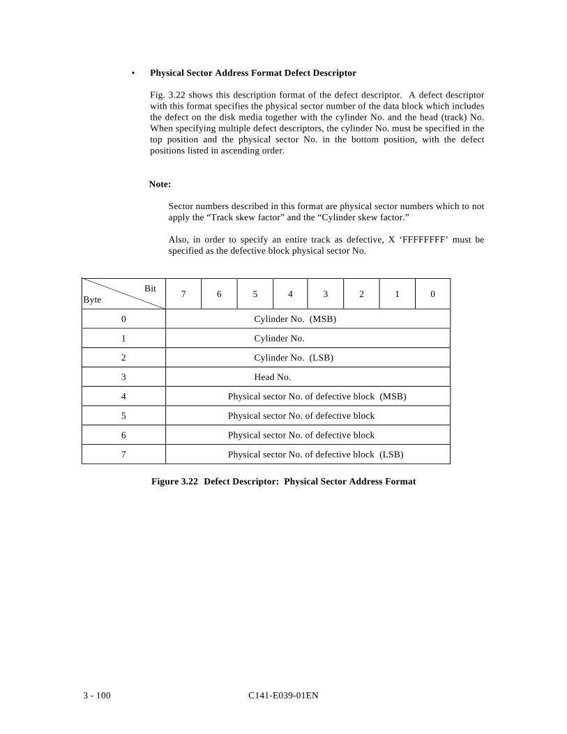
C141-E039-01EN3 - 100
• Physical Sector Address Format Defect Descriptor
Fig. 3.22 shows this description format of the defect descriptor. A defect descriptorwith this format specifies the physical sector number of the data block which includesthe defect on the disk media together with the cylinder No. and the head (track) No.When specifying multiple defect descriptors, the cylinder No. must be specified in thetop position and the physical sector No. in the bottom position, with the defectpositions listed in ascending order.
Note:
Sector numbers described in this format are physical sector numbers which to notapply the “Track skew factor” and the “Cylinder skew factor.”
Also, in order to specify an entire track as defective, X ‘FFFFFFFF’ must bespecified as the defective block physical sector No.
BitByte 7 6 5 4 3 2 1 0
0 Cylinder No. (MSB)
1 Cylinder No.
2 Cylinder No. (LSB)
3 Head No.
4 Physical sector No. of defective block (MSB)
5 Physical sector No. of defective block
6 Physical sector No. of defective block
7 Physical sector No. of defective block (LSB)
Figure 3.22 Defect Descriptor: Physical Sector Address Format
C141-E039-01EN 3 - 101
Cautions in Specifying the D List
The P List, containing defect position information, is always recorded on the IDD when itis shipped from the factory. Also, information on defect positions for which alternateblock processing has been implemented during operation are recorded as the G List. Thefunction which specifies defect position information as the D List when the FORMATUNIT command is executed, is prepared mainly to specify initial defect positioninformation of the disk media which does not have the P List recorded on it. In the IDD,by specifying use of the P List and G List, advance notice of the defect positions can bespecified during initialization, so ordinarily, it is not necessary to use the D List. When theD List is used for the IDD, caution should be exercised in the follow points.
1. The following formula is applied for the maximum number (p = n + m) of defectivesectors (logical data blocks) which make alternate block processing (sector slip oralternate sectors) necessary.
n + 2m ≤ 9,945
where,n is the number of defective sectors to which “sector slip” processing is applied, andm is the number of defective sectors to which “alternate sector” processing is applied.
See Chapter 3 “Data Format” of the “Product Manual” concerning alternate blockprocessing methods. If defect processing which exceeds this limit is specified in theFORMAT UNIT command, that command is terminated with a CHECKCONDITION status (HARDWARE ERROR [=4] / No defect spare location available[-32-00]).
2. A defect descriptor specified as the D List are received normally if the specified defectposition information is within a range which does not exceed the disk drive’s physicalboundaries (User Space), and is recorded as the G List, but formatting processing isexecuted only for the User Space in the range specified in the “Block descriptor” and“Format parameters” (Page 3), and the “Drive parameters” (Page 4) of the MODESELECT parameter.
3. If a defect descriptor in the “Byte distance from the Index format” is specified in theD List, depending on the byte position of the specified defective byte, 2 sectors maybe processed as defective sectors with one defect descriptor, or 1 sector may beprocessed as a defective sector with 2 or more defect descriptors. Also, if thespecified defective byte position has no influence on data block read/write operations,that defect position information is disregarded and is not the object of defective sectorprocessing, and thus is not recorded in the G List. Therefore, the defect positioninformation specified in this command may not necessarily coincide with the defectposition information read with the READ DEFECT DATA command after thiscommand is terminated.
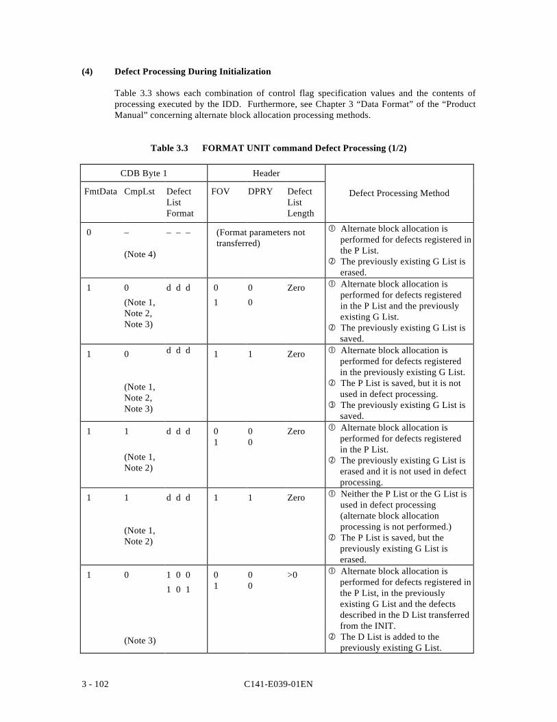
C141-E039-01EN3 - 102
(4) Defect Processing During Initialization
Table 3.3 shows each combination of control flag specification values and the contents ofprocessing executed by the IDD. Furthermore, see Chapter 3 “Data Format” of the “ProductManual” concerning alternate block allocation processing methods.
Table 3.3 FORMAT UNIT command Defect Processing (1/2)
CDB Byte 1 Header
FmtData CmpLst DefectListFormat
FOV DPRY DefectListLength
Defect Processing Method
0 –
(Note 4)
– – – (Format parameters nottransferred)
Alternate block allocation isperformed for defects registered inthe P List.
The previously existing G List iserased.
1 0
(Note 1,Note 2,Note 3)
d d d 0
1
0
0
Zero Alternate block allocation isperformed for defects registeredin the P List and the previouslyexisting G List.
The previously existing G List issaved.
1 0
(Note 1,Note 2,Note 3)
d d d 1 1 Zero Alternate block allocation isperformed for defects registeredin the previously existing G List.
The P List is saved, but it is notused in defect processing.
The previously existing G List issaved.
1 1
(Note 1,Note 2)
d d d 0 1
00
Zero Alternate block allocation isperformed for defects registeredin the P List.
The previously existing G List iserased and it is not used in defectprocessing.
1 1
(Note 1,Note 2)
d d d 1 1 Zero Neither the P List or the G List isused in defect processing(alternate block allocationprocessing is not performed.)
The P List is saved, but thepreviously existing G List iserased.
1 0
(Note 3)
1 0 0
1 0 1
0 1
00
>0 Alternate block allocation isperformed for defects registered inthe P List, in the previouslyexisting G List and the defectsdescribed in the D List transferredfrom the INIT.
The D List is added to thepreviously existing G List.
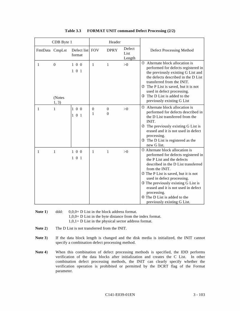
C141-E039-01EN 3 - 103
Table 3.3 FORMAT UNIT command Defect Processing (2/2)
CDB Byte 1 Header
FmtData CmpLst Defect listformat
FOV DPRY DefectListLength
Defect Processing Method
1 0
(Notes1, 3)
1 0 0
1 0 1
1 1 >0 Alternate block allocation isperformed for defects registered inthe previously existing G List andthe defects described in the D Listtransferred from the INIT.
The P List is saved, but it is notused in defect processing.
The D List is added to thepreviously existing G List
1 1 1 0 0
1 0 1
0 1
00
>0 Alternate block allocation isperformed for defects described inthe D List transferred from theINIT.
The previously existing G List iserased and it is not used in defectprocessing.
The D List is registered as thenew G list.
1 1 1 0 0
1 0 1
1 1 >0 Alternate block allocation isperformed for defects registered inthe P List and the defectsdescribed in the D List transferredfrom the INIT.
The P List is saved, but it is notused in defect processing.
The previously existing G List iserased and it is not used in defectprocessing.
The D List is added to thepreviously existing G List.
Note 1) ddd: 0,0,0= D List in the block address format.1,0,0= D List in the byte distance from the index format.1,0,1= D List in the physical sector address format.
Note 2) The D List is not transferred from the INIT.
Note 3) If the data block length is changed and the disk media is initialized, the INIT cannotspecify a combination defect processing method.
Note 4) When this combination of defect processing methods is specified, the IDD performsverification of the data blocks after initialization and creates the C List. In othercombination defect processing methods, the INIT can clearly specify whether theverification operation is prohibited or permitted by the DCRT flag of the Formatparameter.
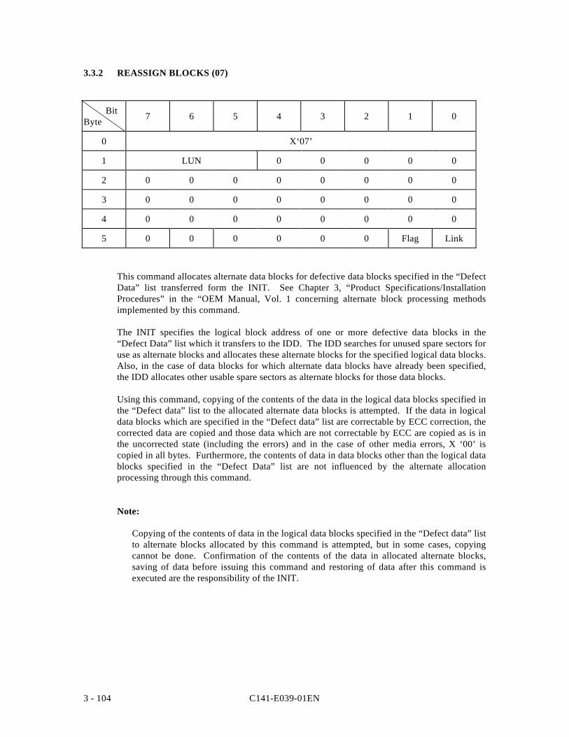
C141-E039-01EN3 - 104
3.3.2 REASSIGN BLOCKS (07)
BitByte 7 6 5 4 3 2 1 0
0 X‘07’
1 LUN 0 0 0 0 0
2 0 0 0 0 0 0 0 0
3 0 0 0 0 0 0 0 0
4 0 0 0 0 0 0 0 0
5 0 0 0 0 0 0 Flag Link
This command allocates alternate data blocks for defective data blocks specified in the “DefectData” list transferred form the INIT. See Chapter 3, “Product Specifications/InstallationProcedures” in the “OEM Manual, Vol. 1 concerning alternate block processing methodsimplemented by this command.
The INIT specifies the logical block address of one or more defective data blocks in the“Defect Data” list which it transfers to the IDD. The IDD searches for unused spare sectors foruse as alternate blocks and allocates these alternate blocks for the specified logical data blocks.Also, in the case of data blocks for which alternate data blocks have already been specified,the IDD allocates other usable spare sectors as alternate blocks for those data blocks.
Using this command, copying of the contents of the data in the logical data blocks specified inthe “Defect data” list to the allocated alternate data blocks is attempted. If the data in logicaldata blocks which are specified in the “Defect data” list are correctable by ECC correction, thecorrected data are copied and those data which are not correctable by ECC are copied as is inthe uncorrected state (including the errors) and in the case of other media errors, X ‘00’ iscopied in all bytes. Furthermore, the contents of data in data blocks other than the logical datablocks specified in the “Defect Data” list are not influenced by the alternate allocationprocessing through this command.
Note:
Copying of the contents of data in the logical data blocks specified in the “Defect data” listto alternate blocks allocated by this command is attempted, but in some cases, copyingcannot be done. Confirmation of the contents of the data in allocated alternate blocks,saving of data before issuing this command and restoring of data after this command isexecuted are the responsibility of the INIT.
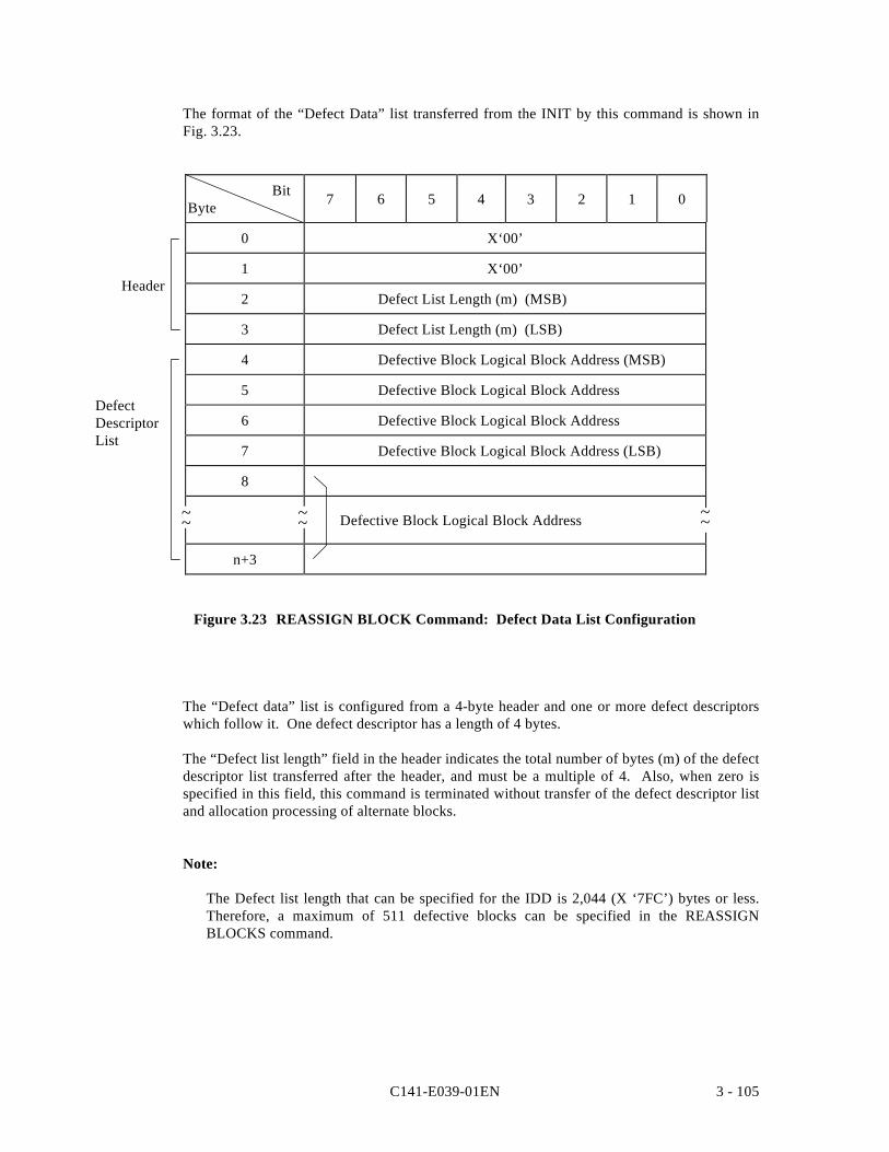
C141-E039-01EN 3 - 105
The format of the “Defect Data” list transferred from the INIT by this command is shown inFig. 3.23.
BitByte 7 6 5 4 3 2 1 0
0 X‘00’
1 X‘00’
2 Defect List Length (m) (MSB)
3 Defect List Length (m) (LSB)
4 Defective Block Logical Block Address (MSB)
5 Defective Block Logical Block Address
6 Defective Block Logical Block Address
7 Defective Block Logical Block Address (LSB)
8
Defective Block Logical Block Address
n+3
Figure 3.23 REASSIGN BLOCK Command: Defect Data List Configuration
The “Defect data” list is configured from a 4-byte header and one or more defect descriptorswhich follow it. One defect descriptor has a length of 4 bytes.
The “Defect list length” field in the header indicates the total number of bytes (m) of the defectdescriptor list transferred after the header, and must be a multiple of 4. Also, when zero isspecified in this field, this command is terminated without transfer of the defect descriptor listand allocation processing of alternate blocks.
Note:
The Defect list length that can be specified for the IDD is 2,044 (X ‘7FC’) bytes or less.Therefore, a maximum of 511 defective blocks can be specified in the REASSIGNBLOCKS command.
~~ ~~
Header
DefectDescriptorList
~~
C141-E039-01EN3 - 106
The logical block address of defective data blocks is described in 4-byte format in the defectdescriptor. When multiple defect descriptors are specified, it is best for the INIT to describedefect descriptors in the ascending order of the logical data block addresses.
Furthermore, if the addresses of logical data blocks specified in the defect descriptor listoverlap each other, This command is terminated with a CHECK CONDITION status(ILLEGAL REQUEST [=5] / Invalid field in parameter list [=26-00] and none of the alternateblock allocation processing in that command is executed.
The IDD allocates alternate blocks to the specified data blocks in order from the top of thedefect descriptor list. When all the usable spare sectors have been used up, and it isimpossible to allocate alternate blocks, execution of this command is terminated at that pointand a CHECK CONDITION status is reported. The sense data at this time indicate thefollowing contents.
• Sense key: 4 = HARDWARE ERROR
• Sense code/Sub-sense code: 32-00 = No defect spare location available
• “VALID” bit: “1”
• Information field Logical block address specified in the defectdescriptor at the point when alternate blockallocation becomes impossible.
• Command inherent information field
Also, when this command is terminated abnormally with a CHECK CONDITION status dueto any one of several other types of error besides the above error, the logical block addressspecified in the first defect descriptor which did not undergo alternate block allocation isreported in the “Command inherent information” field in the sense data. However, if alternateblock allocation processing of the defect descriptors for which alternate block allocation hasnot been implemented cannot be specified, or if alternate block allocation of all the specifieddefect descriptors has been completed, the “Command inherent information” field indicates X‘FFFFFFFF.’
When alternate block allocation processing is successful, the defect position information onthe disk media related to the data blocks specified in the defect descriptor list is recorded onthe disk media as the defect list (G List). The INIT can read the contents of the G List usingthe READ DEFECT DATA command. Also, this command has no influence on the contentsof the primary defect list (P List).
Note:
The defect position information in the G List is physical block addresses (logical datablock addresses are allocated when no defect exists on the disk media). Therefore, thevalues specified in this command’s defect descriptor list (logical block addresses) may notnecessarily be the same as the contents of the G List read by the READ DEFECT DATAcommand after this command is terminated. For details, see the description of the READDEFECT DATA command (item 3.3.3).
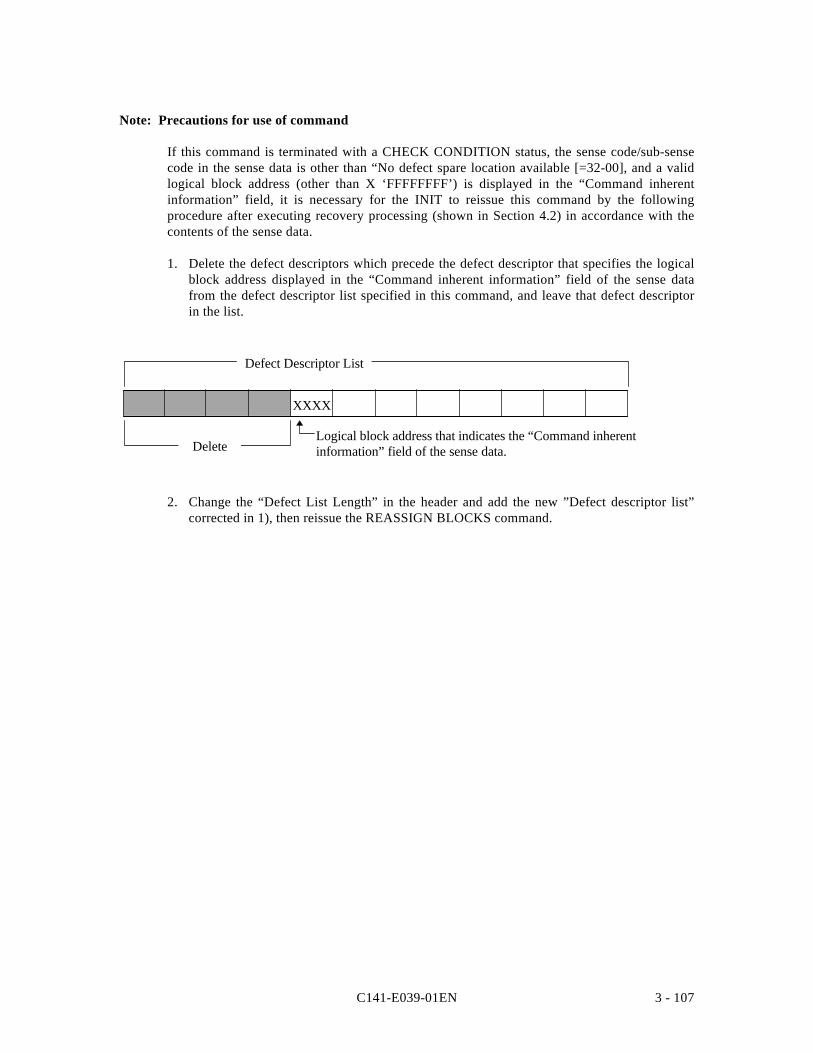
C141-E039-01EN 3 - 107
Note: Precautions for use of command
If this command is terminated with a CHECK CONDITION status, the sense code/sub-sensecode in the sense data is other than “No defect spare location available [=32-00], and a validlogical block address (other than X ‘FFFFFFFF’) is displayed in the “Command inherentinformation” field, it is necessary for the INIT to reissue this command by the followingprocedure after executing recovery processing (shown in Section 4.2) in accordance with thecontents of the sense data.
1. Delete the defect descriptors which precede the defect descriptor that specifies the logicalblock address displayed in the “Command inherent information” field of the sense datafrom the defect descriptor list specified in this command, and leave that defect descriptorin the list.
Logical block address that indicates the “Command inherentinformation” field of the sense data.
XXXX
Defect Descriptor List
Delete
2. Change the “Defect List Length” in the header and add the new ”Defect descriptor list”corrected in 1), then reissue the REASSIGN BLOCKS command.
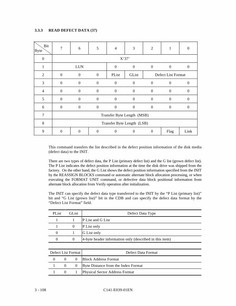
C141-E039-01EN3 - 108
3.3.3 READ DEFECT DATA (37)
BitByte 7 6 5 4 3 2 1 0
0 X‘37’
1 LUN 0 0 0 0 0
2 0 0 0 PList GList Defect List Format
3 0 0 0 0 0 0 0 0
4 0 0 0 0 0 0 0 0
5 0 0 0 0 0 0 0 0
6 0 0 0 0 0 0 0 0
7 Transfer Byte Length (MSB)
8 Transfer Byte Length (LSB)
9 0 0 0 0 0 0 Flag Link
This command transfers the list described in the defect position information of the disk media(defect data) to the INIT.
There are two types of defect data, the P List (primary defect list) and the G list (grown defect list).The P List indicates the defect position information at the time the disk drive was shipped from thefactory. On the other hand, the G List shows the defect position information specified from the INITby the REASSIGN BLOCKS command or automatic alternate block allocation processing, or whenexecuting the FORMAT UNIT command, or defective data block positional information fromalternate block allocation from Verify operation after initialization.
The INIT can specify the defect data type transferred to the INIT by the “P List (primary list)”bit and “G List (grown list)” bit in the CDB and can specify the defect data format by the“Defect List Format” field.
PList GList Defect Data Type
1 1 P List and G List
1 0 P List only
0 1 G List only
0 0 4-byte header information only (described in this item)
Defect List Format Defect Data Format
0 0 0 Block Address Format
1 0 0 Byte Distance from the Index Format
1 0 1 Physical Sector Address Format
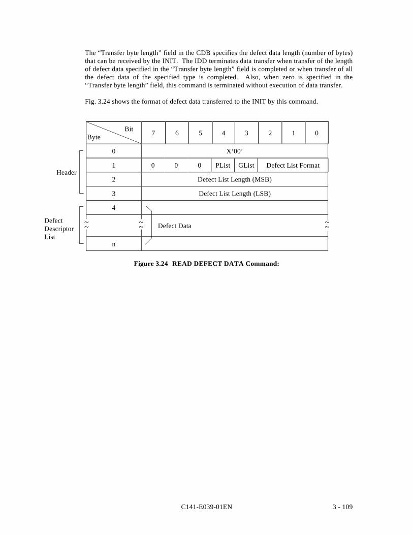
C141-E039-01EN 3 - 109
The “Transfer byte length” field in the CDB specifies the defect data length (number of bytes)that can be received by the INIT. The IDD terminates data transfer when transfer of the lengthof defect data specified in the “Transfer byte length” field is completed or when transfer of allthe defect data of the specified type is completed. Also, when zero is specified in the“Transfer byte length” field, this command is terminated without execution of data transfer.
Fig. 3.24 shows the format of defect data transferred to the INIT by this command.
BitByte 7 6 5 4 3 2 1 0
0 X‘00’
1 0 0 0 PList GList Defect List Format
2 Defect List Length (MSB)
3 Defect List Length (LSB)
4
Defect Data
n
Figure 3.24 READ DEFECT DATA Command:
~~ ~~
Header
DefectDescriptorList
~~
C141-E039-01EN3 - 110
(1) Header
a. P List (primary list) Bit
When this bit is “1,” it indicates that P List defect data are included in the defect descriptorlist that is actually transferred to the INIT. When it is “0,” it indicates that the P List defectdata are not included. See 3) of item (2).)
b. G List (grown list) Bit
When this bit is “1,” it indicates that G List defect data are included in the defect descriptorlist that is actually transferred to the INIT. When it is “0,” it indicates that the G Listdefect data are not included. See 3) of item (2).)
c. Defect List Format
This field indicates the description format of the defect descriptor list that is actuallytransferred to the INIT. It is possible for the IDD to transfer defect data in 3 differentformats which it can specify in the CDB, and the values in this field are the same as thevalues specified in the “Defect List Format” field in the CDB.
d. Defect List Length
This field follows the 4-byte header and indicates the total number of bytes of defectdescriptor list that can be transferred. It has either 4 or 8 bytes, depending on the format ofthe defect descriptor. Also, the values shown in this field are the total number of bytesdescribed in the “Defect List Format” which specifies the specified type (P List or G List)of defect data, regardless of the value specified in the “Transfer byte length” field in theCDB. The INIT should check whether the value shown in this field plus 4 is a smallervalue than that specified in the “Transfer byte count” field in the CDB in order to confirmthat all the defect data requested in this command have been transferred. Also, since thevalue shown in this field is divided by the number of bytes (4 or 8) per defect descriptor(quotient), the INIT can know the number of defects on the disk media.
(2) Defect Descriptor List
The data transferred after the 4-byte header is the “Defect descriptor” list (Defect data) inwhich the defect position information are described with the type and format specified in theCDB. One “Defect descriptor” has a length of 4 bytes when in the “Block address format,”and a length of 8 bytes when in the “Byte distance from the index format” and “Physical sectoraddress format.” The “Defect descriptors” do not necessarily transfer defect positioninformation in ascending order.
See the description of the FORMAT UNIT command (item 3.3.1) concerning theconfiguration and contents of the “Defect descriptor” in each format.
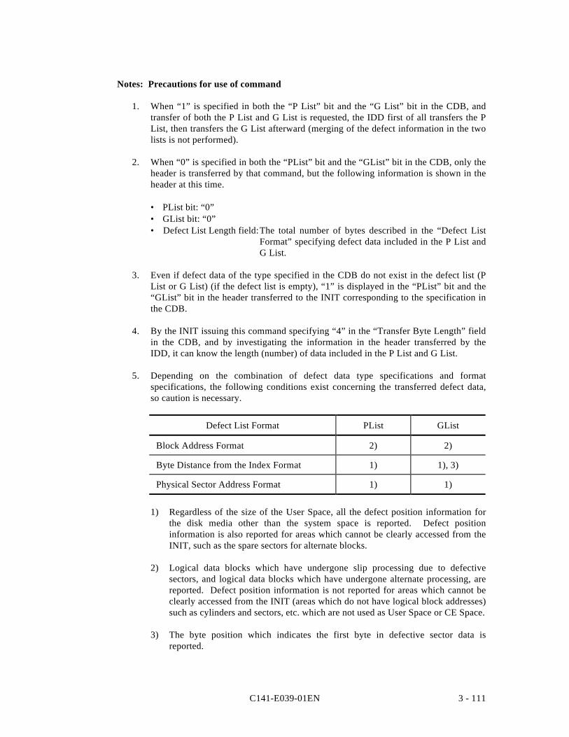
C141-E039-01EN 3 - 111
Notes: Precautions for use of command
1. When “1” is specified in both the “P List” bit and the “G List” bit in the CDB, andtransfer of both the P List and G List is requested, the IDD first of all transfers the PList, then transfers the G List afterward (merging of the defect information in the twolists is not performed).
2. When “0” is specified in both the “PList” bit and the “GList” bit in the CDB, only theheader is transferred by that command, but the following information is shown in theheader at this time.
• PList bit: “0”• GList bit: “0”• Defect List Length field:The total number of bytes described in the “Defect List
Format” specifying defect data included in the P List andG List.
3. Even if defect data of the type specified in the CDB do not exist in the defect list (PList or G List) (if the defect list is empty), “1” is displayed in the “PList” bit and the“GList” bit in the header transferred to the INIT corresponding to the specification inthe CDB.
4. By the INIT issuing this command specifying “4” in the “Transfer Byte Length” fieldin the CDB, and by investigating the information in the header transferred by theIDD, it can know the length (number) of data included in the P List and G List.
5. Depending on the combination of defect data type specifications and formatspecifications, the following conditions exist concerning the transferred defect data,so caution is necessary.
Defect List Format PList GList
Block Address Format 2) 2)
Byte Distance from the Index Format 1) 1), 3)
Physical Sector Address Format 1) 1)
1) Regardless of the size of the User Space, all the defect position information forthe disk media other than the system space is reported. Defect positioninformation is also reported for areas which cannot be clearly accessed from theINIT, such as the spare sectors for alternate blocks.
2) Logical data blocks which have undergone slip processing due to defectivesectors, and logical data blocks which have undergone alternate processing, arereported. Defect position information is not reported for areas which cannot beclearly accessed from the INIT (areas which do not have logical block addresses)such as cylinders and sectors, etc. which are not used as User Space or CE Space.
3) The byte position which indicates the first byte in defective sector data isreported.
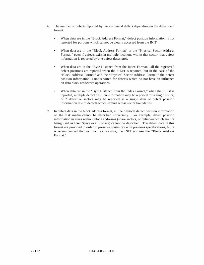
C141-E039-01EN3 - 112
6. The number of defects reported by this command differs depending on the defect dataformat.
• When data are in the “Block Address Format,” defect position information is notreported for portions which cannot be clearly accessed from the INIT.
• When data are in the “Block Address Format” or the “Physical Sector AddressFormat,” even if defects exist in multiple locations within that sector, that defectinformation is reported by one defect descriptor.
• When data are in the “Byte Distance from the Index Format,” all the registereddefect positions are reported when the P List is reported, but in the case of the“Block Address Format” and the “Physical Sector Address Format,” the defectposition information is not reported for defects which do not have an influenceon data block read/write operations.
• When data are in the “Byte Distance from the Index Format,” when the P List isreported, multiple defect position information may be reported for a single sector,or 2 defective sectors may be reported as a single item of defect positioninformation due to defects which extend across sector boundaries.
7. In defect data in the block address format, all the physical defect position informationon the disk media cannot be described universally. For example, defect positioninformation in areas without block addresses (spare sectors, or cylinders which are notbeing used as User Space or CE Space) cannot be described. The defect data in thisformat are provided in order to preserve continuity with previous specifications, but itis recommended that as much as possible, the INIT not use the “Block AddressFormat.”
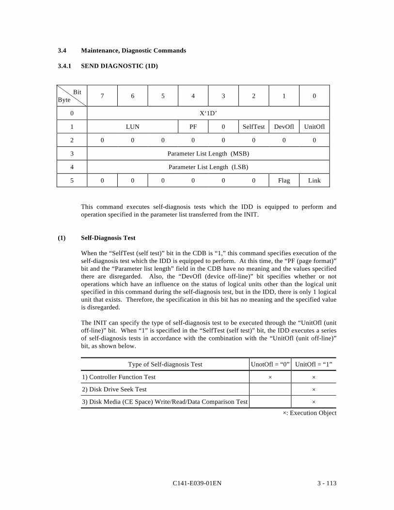
C141-E039-01EN 3 - 113
3.4 Maintenance, Diagnostic Commands
3.4.1 SEND DIAGNOSTIC (1D)
BitByte 7 6 5 4 3 2 1 0
0 X‘1D’
1 LUN PF 0 SelfTest DevOfl UnitOfl
2 0 0 0 0 0 0 0 0
3 Parameter List Length (MSB)
4 Parameter List Length (LSB)
5 0 0 0 0 0 0 Flag Link
This command executes self-diagnosis tests which the IDD is equipped to perform andoperation specified in the parameter list transferred from the INIT.
(1) Self-Diagnosis Test
When the “SelfTest (self test)” bit in the CDB is “1,” this command specifies execution of theself-diagnosis test which the IDD is equipped to perform. At this time, the “PF (page format)”bit and the “Parameter list length” field in the CDB have no meaning and the values specifiedthere are disregarded. Also, the “DevOfl (device off-line)” bit specifies whether or notoperations which have an influence on the status of logical units other than the logical unitspecified in this command during the self-diagnosis test, but in the IDD, there is only 1 logicalunit that exists. Therefore, the specification in this bit has no meaning and the specified valueis disregarded.
The INIT can specify the type of self-diagnosis test to be executed through the “UnitOfl (unitoff-line)” bit. When “1” is specified in the “SelfTest (self test)” bit, the IDD executes a seriesof self-diagnosis tests in accordance with the combination with the “UnitOfl (unit off-line)”bit, as shown below.
Type of Self-diagnosis Test UnotOfl = “0” UnitOfl = “1”
1) Controller Function Test × ×
2) Disk Drive Seek Test ×
3) Disk Media (CE Space) Write/Read/Data Comparison Test ×
×: Execution Object
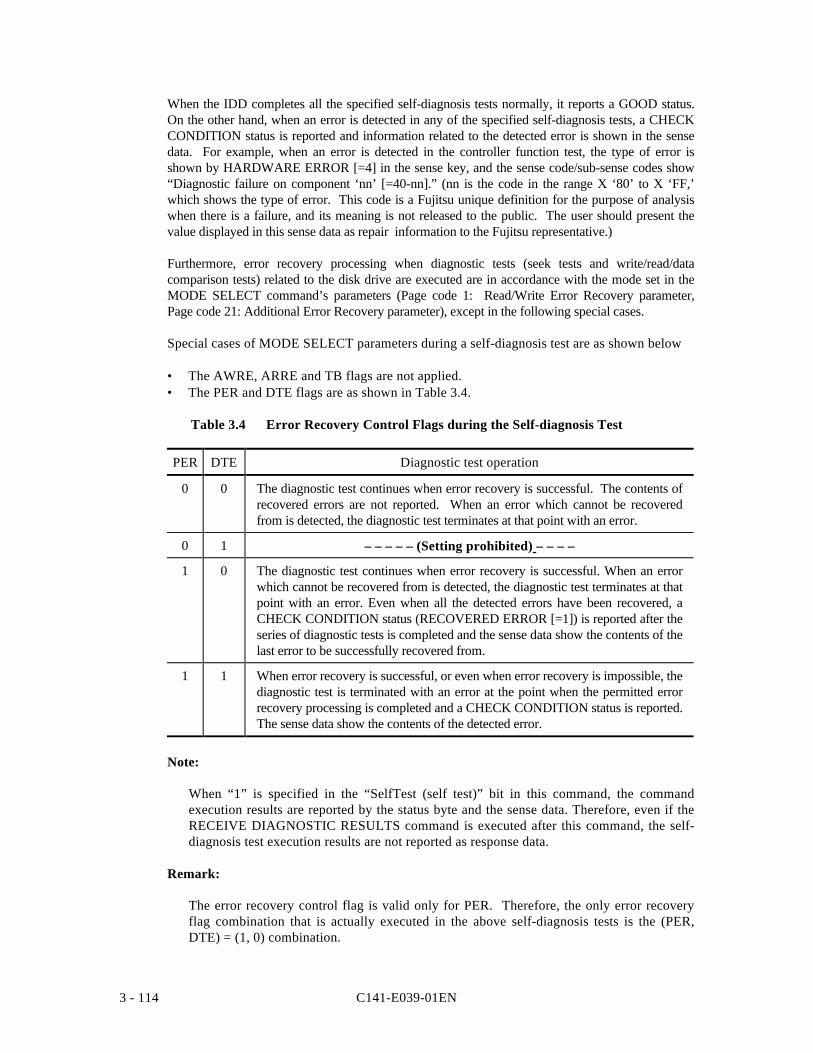
C141-E039-01EN3 - 114
When the IDD completes all the specified self-diagnosis tests normally, it reports a GOOD status.On the other hand, when an error is detected in any of the specified self-diagnosis tests, a CHECKCONDITION status is reported and information related to the detected error is shown in the sensedata. For example, when an error is detected in the controller function test, the type of error isshown by HARDWARE ERROR [=4] in the sense key, and the sense code/sub-sense codes show“Diagnostic failure on component ‘nn’ [=40-nn].” (nn is the code in the range X ‘80’ to X ‘FF,’which shows the type of error. This code is a Fujitsu unique definition for the purpose of analysiswhen there is a failure, and its meaning is not released to the public. The user should present thevalue displayed in this sense data as repair information to the Fujitsu representative.)
Furthermore, error recovery processing when diagnostic tests (seek tests and write/read/datacomparison tests) related to the disk drive are executed are in accordance with the mode set in theMODE SELECT command’s parameters (Page code 1: Read/Write Error Recovery parameter,Page code 21: Additional Error Recovery parameter), except in the following special cases.
Special cases of MODE SELECT parameters during a self-diagnosis test are as shown below
• The AWRE, ARRE and TB flags are not applied.• The PER and DTE flags are as shown in Table 3.4.
Table 3.4 Error Recovery Control Flags during the Self-diagnosis Test
PER DTE Diagnostic test operation
0 0 The diagnostic test continues when error recovery is successful. The contents ofrecovered errors are not reported. When an error which cannot be recoveredfrom is detected, the diagnostic test terminates at that point with an error.
0 1 – – – – – (Setting prohibited) – – – –
1 0 The diagnostic test continues when error recovery is successful. When an errorwhich cannot be recovered from is detected, the diagnostic test terminates at thatpoint with an error. Even when all the detected errors have been recovered, aCHECK CONDITION status (RECOVERED ERROR [=1]) is reported after theseries of diagnostic tests is completed and the sense data show the contents of thelast error to be successfully recovered from.
1 1 When error recovery is successful, or even when error recovery is impossible, thediagnostic test is terminated with an error at the point when the permitted errorrecovery processing is completed and a CHECK CONDITION status is reported.The sense data show the contents of the detected error.
Note:
When “1” is specified in the “SelfTest (self test)” bit in this command, the commandexecution results are reported by the status byte and the sense data. Therefore, even if theRECEIVE DIAGNOSTIC RESULTS command is executed after this command, the self-diagnosis test execution results are not reported as response data.
Remark:
The error recovery control flag is valid only for PER. Therefore, the only error recoveryflag combination that is actually executed in the above self-diagnosis tests is the (PER,DTE) = (1, 0) combination.
C141-E039-01EN 3 - 115
(2) Parameter Specification
When “0” is specified in the “SelfTest (self test) bit in the CDB, the IDD executes theoperations specified in the parameter list transferred from the INIT by this command. In thiscase, the IDD reports a GOOD status and terminates this command at the point whenpreparation of the “response data” is completed after completing the specified operations. TheINIT can read the execution results (response data) by the RECEIVE DIAGNOSTICRESULTS command.
When the “PF (page format)” bit in the CDB is “1,” the parameter list transferred from theINIT by this command shows the page format, explained later, but the IDD disregards thevalue specified in this bit and always handles the page format according to the specificationsin the parameter list when the parameter list is transferred by this command. Also, when the“SelfTest (self test)” bit is “0,” the specifications in the “DefOfl (device off-line)” bit and the“UnitOfl (unit off-line)” bit have no meaning and their specified values are disregarded.
The “Parameter list length” field in the CDB shows the length (number of bytes) of theparameter list that is transferred from the INIT when the “SelfTest (self test)” bit’sspecification is “0.” When zero is specified in the “Parameter list length” field, this commandis terminated without anything being executed. Also, when the value specified in the“Parameter list length” field does not reach the specified length for the parameter list,explained later, and as a result, not all the bytes in the parameter list can be received, thatcommand is terminated with a CHECK CONDITION status (ILLEGAL REQUEST) [=5] /Invalid field in CDB [=24-00]).
Fig. 3.35 shows the format of the parameter list (called the parameter page) transferred fromthe INIT to the IDD by this command. The parameter page is configured from the 4-byte“Page Header” and the “Page Parameters” which follow it. Furthermore, the INIT can specifyonly a single parameter page by this command. Even when multiple parameter pages havebeen specified by the INIT, the IDD executes only the operation specified by the top parameterpage.
Notes
1. When “0” is specified in the “SelfTest (self test)” bit in this command, the INIT canspecify only a single parameter page.
2. In order to avoid loss of security to the execution results (response data) of thiscommand due to another command issued by another INIT, when “0” is specified inthe “SelfTest (self test)” bit, the INIT should issue this command linked to theRECEIVE DIAGNOSTIC RESULTS command or reserve the IDD before issuing thiscommand, and should release the reserve status after executing the RECEIVEDIAGNOSTIC RESULTS command.
3. When a command other than the RECEIVE DIAGNOSTIC RESULTS command islinked to this command, the execution results (response data) may no longer besecure.
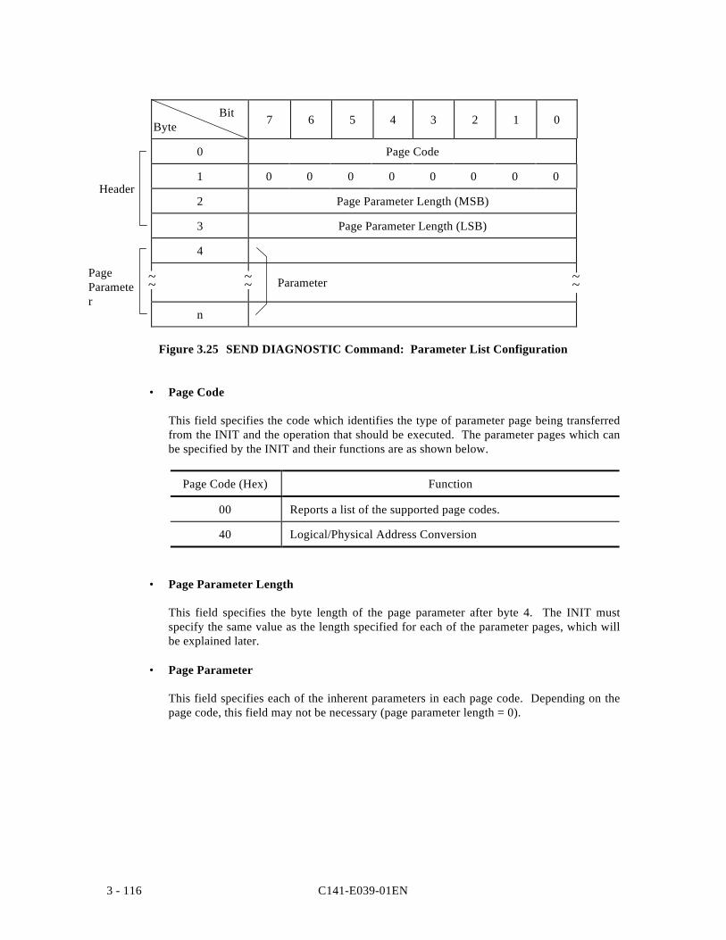
C141-E039-01EN3 - 116
BitByte 7 6 5 4 3 2 1 0
0 Page Code
1 0 0 0 0 0 0 0 0
2 Page Parameter Length (MSB)
3 Page Parameter Length (LSB)
4
Parameter
n
Figure 3.25 SEND DIAGNOSTIC Command: Parameter List Configuration
• Page Code
This field specifies the code which identifies the type of parameter page being transferredfrom the INIT and the operation that should be executed. The parameter pages which canbe specified by the INIT and their functions are as shown below.
Page Code (Hex) Function
00 Reports a list of the supported page codes.
40 Logical/Physical Address Conversion
• Page Parameter Length
This field specifies the byte length of the page parameter after byte 4. The INIT mustspecify the same value as the length specified for each of the parameter pages, which willbe explained later.
• Page Parameter
This field specifies each of the inherent parameters in each page code. Depending on thepage code, this field may not be necessary (page parameter length = 0).
~~ ~~~~
Header
PageParameter
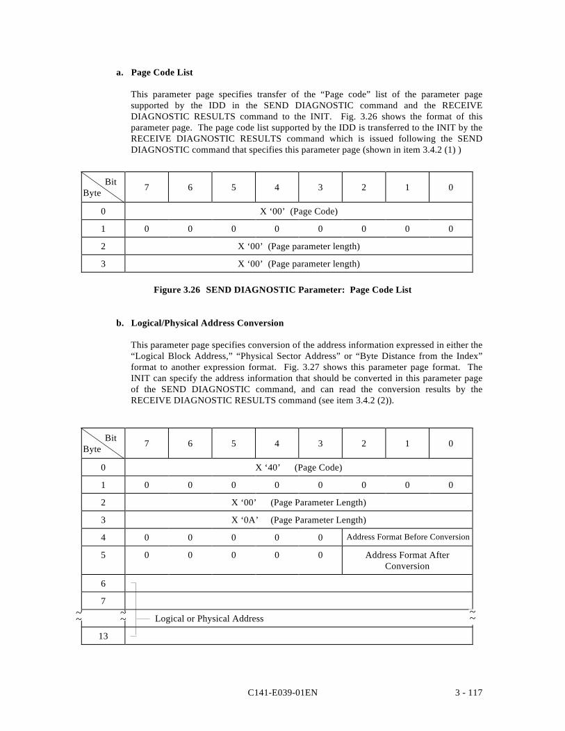
C141-E039-01EN 3 - 117
a. Page Code List
This parameter page specifies transfer of the “Page code” list of the parameter pagesupported by the IDD in the SEND DIAGNOSTIC command and the RECEIVEDIAGNOSTIC RESULTS command to the INIT. Fig. 3.26 shows the format of thisparameter page. The page code list supported by the IDD is transferred to the INIT by theRECEIVE DIAGNOSTIC RESULTS command which is issued following the SENDDIAGNOSTIC command that specifies this parameter page (shown in item 3.4.2 (1) )
BitByte 7 6 5 4 3 2 1 0
0 X ‘00’ (Page Code)
1 0 0 0 0 0 0 0 0
2 X ‘00’ (Page parameter length)
3 X ‘00’ (Page parameter length)
Figure 3.26 SEND DIAGNOSTIC Parameter: Page Code List
b. Logical/Physical Address Conversion
This parameter page specifies conversion of the address information expressed in either the“Logical Block Address,” “Physical Sector Address” or “Byte Distance from the Index”format to another expression format. Fig. 3.27 shows this parameter page format. TheINIT can specify the address information that should be converted in this parameter pageof the SEND DIAGNOSTIC command, and can read the conversion results by theRECEIVE DIAGNOSTIC RESULTS command (see item 3.4.2 (2)).
BitByte 7 6 5 4 3 2 1 0
0 X ‘40’ (Page Code)
1 0 0 0 0 0 0 0 0
2 X ‘00’ (Page Parameter Length)
3 X ‘0A’ (Page Parameter Length)
4 0 0 0 0 0 Address Format Before Conversion
5 0 0 0 0 0 Address Format AfterConversion
6
7
Logical or Physical Address
13
~~~~~~
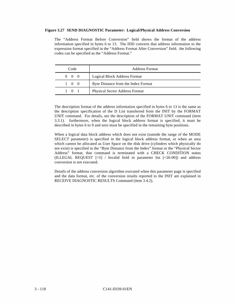
C141-E039-01EN3 - 118
Figure 3.27 SEND DIAGNOSTIC Parameter: Logical/Physical Address Conversion
The “Address Format Before Conversion” field shows the format of the addressinformation specified in bytes 6 to 13. The IDD converts that address information to theexpression format specified in the “Address Format After Conversion” field. the followingcodes can be specified as the “Address Format.”
Code Address Format
0 0 0 Logical Block Address Format
1 0 0 Byte Distance from the Index Format
1 0 1 Physical Sector Address Format
The description format of the address information specified in bytes 6 to 13 is the same asthe description specification of the D List transferred from the INIT by the FORMATUNIT command. For details, see the description of the FORMAT UNIT command (item3.3.1). furthermore, when the logical block address format is specified, it must bedescribed in bytes 6 to 9 and zero must be specified in the remaining byte positions.
When a logical data block address which does not exist (outside the range of the MODESELECT parameter) is specified in the logical block address format, or when an areawhich cannot be allocated as User Space on the disk drive (cylinders which physically donot exist) is specified in the “Byte Distance from the Index” format or the “Physical SectorAddress” format, that command is terminated with a CHECK CONDITION status(ILLEGAL REQUEST [=5] / Invalid field in parameter list [=26-00]) and addressconversion is not executed.
Details of the address conversion algorithm executed when this parameter page is specifiedand the data format, etc. of the conversion results reported to the INIT are explained inRECEIVE DIAGNOSTIC RESULTS Command (item 3.4.2).
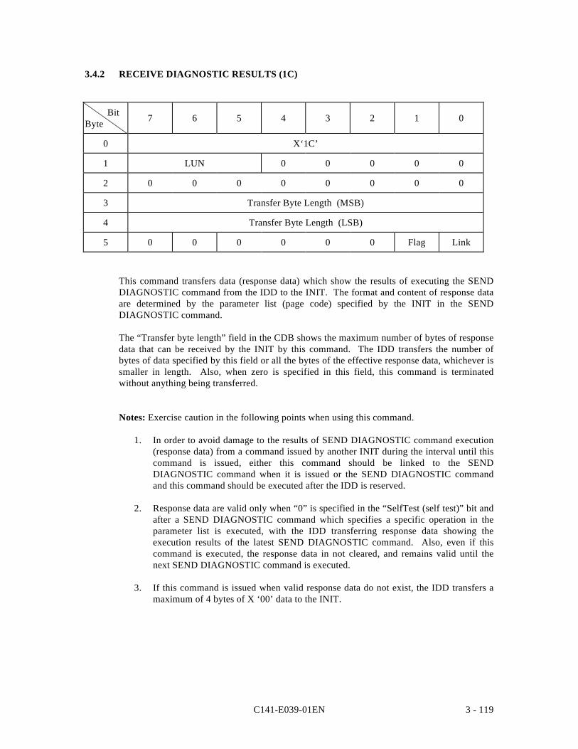
C141-E039-01EN 3 - 119
3.4.2 RECEIVE DIAGNOSTIC RESULTS (1C)
BitByte 7 6 5 4 3 2 1 0
0 X‘1C’
1 LUN 0 0 0 0 0
2 0 0 0 0 0 0 0 0
3 Transfer Byte Length (MSB)
4 Transfer Byte Length (LSB)
5 0 0 0 0 0 0 Flag Link
This command transfers data (response data) which show the results of executing the SENDDIAGNOSTIC command from the IDD to the INIT. The format and content of response dataare determined by the parameter list (page code) specified by the INIT in the SENDDIAGNOSTIC command.
The “Transfer byte length” field in the CDB shows the maximum number of bytes of responsedata that can be received by the INIT by this command. The IDD transfers the number ofbytes of data specified by this field or all the bytes of the effective response data, whichever issmaller in length. Also, when zero is specified in this field, this command is terminatedwithout anything being transferred.
Notes: Exercise caution in the following points when using this command.
1. In order to avoid damage to the results of SEND DIAGNOSTIC command execution(response data) from a command issued by another INIT during the interval until thiscommand is issued, either this command should be linked to the SENDDIAGNOSTIC command when it is issued or the SEND DIAGNOSTIC commandand this command should be executed after the IDD is reserved.
2. Response data are valid only when “0” is specified in the “SelfTest (self test)” bit andafter a SEND DIAGNOSTIC command which specifies a specific operation in theparameter list is executed, with the IDD transferring response data showing theexecution results of the latest SEND DIAGNOSTIC command. Also, even if thiscommand is executed, the response data in not cleared, and remains valid until thenext SEND DIAGNOSTIC command is executed.
3. If this command is issued when valid response data do not exist, the IDD transfers amaximum of 4 bytes of X ‘00’ data to the INIT.
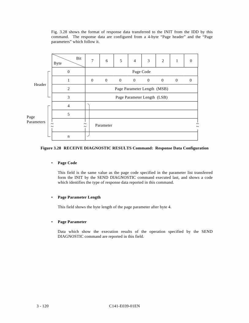
C141-E039-01EN3 - 120
Fig. 3.28 shows the format of response data transferred to the INIT from the IDD by thiscommand. The response data are configured from a 4-byte “Page header” and the “Pageparameters” which follow it.
Bit Byte 7 6 5 4 3 2 1 0
0 Page Code
1 0 0 0 0 0 0 0 0
2 Page Parameter Length (MSB)
3 Page Parameter Length (LSB)
4
5
Parameter
n
Figure 3.28 RECEIVE DIAGNOSTIC RESULTS Command: Response Data Configuration
• Page Code
This field is the same value as the page code specified in the parameter list transferredform the INIT by the SEND DIAGNOSTIC command executed last, and shows a codewhich identifies the type of response data reported in this command.
• Page Parameter Length
This field shows the byte length of the page parameter after byte 4.
• Page Parameter
Data which show the execution results of the operation specified by the SENDDIAGNOSTIC command are reported in this field.
~~ ~~~~
Header
PageParameters
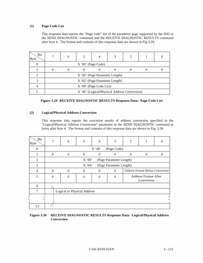
C141-E039-01EN 3 - 121
(1) Page Code List
This response data reports the “Page code” list of the parameter page supported by the IDD inthe SEND DIAGNOSTIC command and the RECEIVE DIAGNOSTIC RESULTS commandafter byte 4. The format and contents of this response data are shown in Fig 3.29.
BitByte 7 6 5 4 3 2 1 0
0 X ‘00’ (Page Code)
1 0 0 0 0 0 0 0 0
2 X ‘00’ (Page Parameter Length)
3 X ‘02’ (Page Parameter Length)
4 X ‘00’ (Page Code List)
5 X ‘40’ (Logical/Physical Address Conversion)
Figure 3.29 RECEIVE DIAGNOSTIC RESULTS Response Data: Page Code List
(2) Logical/Physical Address Conversion
This response data reports the execution results of address conversion specified in the“Logical/Physical Address Conversion” parameter in the SEND DIAGNOSTIC command inbytes after byte 4. The format and contents of this response data are shown in Fig. 3.30.
BitByte 7 6 5 4 3 2 1 0
0 X ‘40’ (Page Code)
1 0 0 0 0 0 0 0 0
2 X ‘00’ (Page Parameter Length)
3 X ‘0A’ (Page Parameter Length)
4 0 0 0 0 0 Address Format Before Conversion
5 0 0 0 0 0 Address Format AfterConversion
6
7 Logical or Physical Address
13
Figure 3.30 RECEIVE DIAGNOSTIC RESULTS Response Data: Logical/Physical AddressConversion
~~ ~~~~
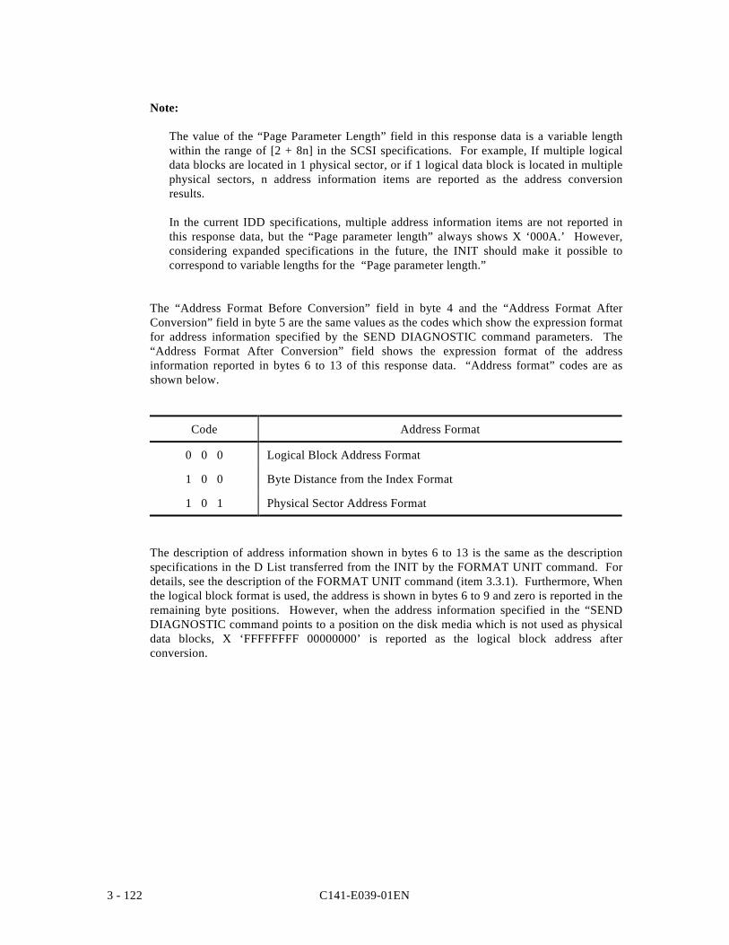
C141-E039-01EN3 - 122
Note:
The value of the “Page Parameter Length” field in this response data is a variable lengthwithin the range of [2 + 8n] in the SCSI specifications. For example, If multiple logicaldata blocks are located in 1 physical sector, or if 1 logical data block is located in multiplephysical sectors, n address information items are reported as the address conversionresults.
In the current IDD specifications, multiple address information items are not reported inthis response data, but the “Page parameter length” always shows X ‘000A.’ However,considering expanded specifications in the future, the INIT should make it possible tocorrespond to variable lengths for the “Page parameter length.”
The “Address Format Before Conversion” field in byte 4 and the “Address Format AfterConversion” field in byte 5 are the same values as the codes which show the expression formatfor address information specified by the SEND DIAGNOSTIC command parameters. The“Address Format After Conversion” field shows the expression format of the addressinformation reported in bytes 6 to 13 of this response data. “Address format” codes are asshown below.
Code Address Format
0 0 0 Logical Block Address Format
1 0 0 Byte Distance from the Index Format
1 0 1 Physical Sector Address Format
The description of address information shown in bytes 6 to 13 is the same as the descriptionspecifications in the D List transferred from the INIT by the FORMAT UNIT command. Fordetails, see the description of the FORMAT UNIT command (item 3.3.1). Furthermore, Whenthe logical block format is used, the address is shown in bytes 6 to 9 and zero is reported in theremaining byte positions. However, when the address information specified in the “SENDDIAGNOSTIC command points to a position on the disk media which is not used as physicaldata blocks, X ‘FFFFFFFF 00000000’ is reported as the logical block address afterconversion.
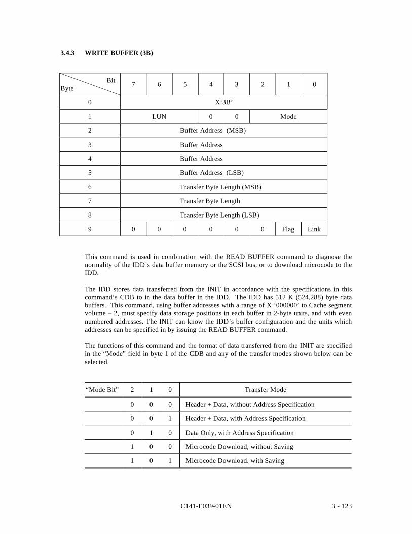
C141-E039-01EN 3 - 123
3.4.3 WRITE BUFFER (3B)
BitByte 7 6 5 4 3 2 1 0
0 X‘3B’
1 LUN 0 0 Mode
2 Buffer Address (MSB)
3 Buffer Address
4 Buffer Address
5 Buffer Address (LSB)
6 Transfer Byte Length (MSB)
7 Transfer Byte Length
8 Transfer Byte Length (LSB)
9 0 0 0 0 0 0 Flag Link
This command is used in combination with the READ BUFFER command to diagnose thenormality of the IDD’s data buffer memory or the SCSI bus, or to download microcode to theIDD.
The IDD stores data transferred from the INIT in accordance with the specifications in thiscommand’s CDB to in the data buffer in the IDD. The IDD has 512 K (524,288) byte databuffers. This command, using buffer addresses with a range of X ‘000000’ to Cache segmentvolume – 2, must specify data storage positions in each buffer in 2-byte units, and with evennumbered addresses. The INIT can know the IDD’s buffer configuration and the units whichaddresses can be specified in by issuing the READ BUFFER command.
The functions of this command and the format of data transferred from the INIT are specifiedin the “Mode” field in byte 1 of the CDB and any of the transfer modes shown below can beselected.
“Mode Bit” 2 1 0 Transfer Mode
0 0 0 Header + Data, without Address Specification
0 0 1 Header + Data, with Address Specification
0 1 0 Data Only, with Address Specification
1 0 0 Microcode Download, without Saving
1 0 1 Microcode Download, with Saving
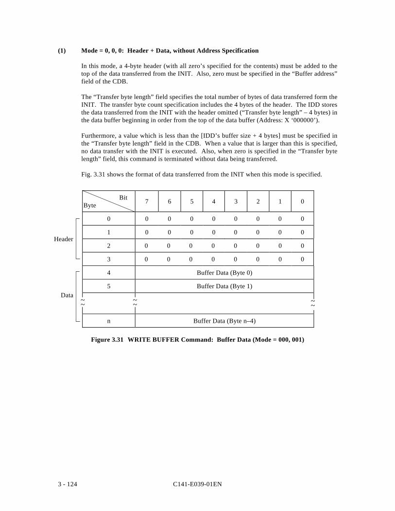
C141-E039-01EN3 - 124
(1) Mode = 0, 0, 0: Header + Data, without Address Specification
In this mode, a 4-byte header (with all zero’s specified for the contents) must be added to thetop of the data transferred from the INIT. Also, zero must be specified in the “Buffer address”field of the CDB.
The “Transfer byte length” field specifies the total number of bytes of data transferred form theINIT. The transfer byte count specification includes the 4 bytes of the header. The IDD storesthe data transferred from the INIT with the header omitted (“Transfer byte length” – 4 bytes) inthe data buffer beginning in order from the top of the data buffer (Address: X ‘000000’).
Furthermore, a value which is less than the [IDD’s buffer size + 4 bytes] must be specified inthe “Transfer byte length” field in the CDB. When a value that is larger than this is specified,no data transfer with the INIT is executed. Also, when zero is specified in the “Transfer bytelength” field, this command is terminated without data being transferred.
Fig. 3.31 shows the format of data transferred from the INIT when this mode is specified.
BitByte 7 6 5 4 3 2 1 0
0 0 0 0 0 0 0 0 0
1 0 0 0 0 0 0 0 0
2 0 0 0 0 0 0 0 0
3 0 0 0 0 0 0 0 0
4 Buffer Data (Byte 0)
5 Buffer Data (Byte 1)
n Buffer Data (Byte n–4)
Figure 3.31 WRITE BUFFER Command: Buffer Data (Mode = 000, 001)
~~ ~~~~
Header
Data
C141-E039-01EN 3 - 125
(2) Mode = 0, 0, 1 : Header + Data, without Address Specification
The format of data transferred from the INIT in this mode must be the same as in the case ofMode = 0, 0, 0, and the 4-byte header (with zero specified in all its contents) must be added tothem.
In this mode, the top address of the data buffer where the data transferred from the INIT arestored can be specified in the “Buffer address” field in the CDB.
The “Transfer byte length” field in the CDB specifies the total number of bytes of datatransferred by the INIT. The transfer byte count specification includes the 4 bytes of theheader. The IDD stores data transferred from the INIT, in a length in which the number ofbytes in the header has been deleted from the data (“Transfer byte length” – 4 bytes) in thedata buffer beginning at the byte position specified in the “Buffer address” field in the CDB.
Furthermore, a value less than the [“IDD’s buffer size” – value specified in the “Bufferaddress” field – 4 bytes] must be specified in the “Transfer byte length” field in the CDB.When a value larger than that is specified, data transfer is not executed with the INIT. Also,when zero is specified in the “Transfer byte length” field, this command is terminated withoutdata transfer being executed.
(3) Mode = 0, 1, 0 : Data only, with Address Specification
In this mode, data transfer from the INIT includes buffer data only without the 4-byte headerbeing added.
The top address of the data buffer where the data transferred from the INIT are to be stored canbe specified in the “Buffer address” field.
The “Transfer byte length” field in the CDB specifies the total number of bytes of datatransferred by the INIT. The IDD stores data transferred from the INIT in the data bufferbeginning at the byte position specified in the “Buffer address” field in the CDB.
Furthermore, a value less than the [“IDD’s buffer size” – value specified in the “Bufferaddress” field] must be specified in the “Transfer byte length” field in the CDB. When a valuelarger than that is specified, data transfer is not executed with the INIT. Also, when zero isspecified in the “Transfer byte length” field, this command is terminated without data transferbeing executed.
C141-E039-01EN3 - 126
(4) Mode = 1, 0, 0 : Microcode Download, without Saving
In this mode, the controller’s microcode or control information is transferred to the IDD’scontrol memory area. “0” must be specified in the “Buffer ID” field and the “Buffer address”field.
The “Transfer byte length” field specifies the total number of transfer bytes of data transferredfrom the INIT. This value must not exceed X ‘080000’ (524,288 bytes). If a value greaterthan X ‘080000’ is specified, a CHECK CONDITION status (ILLEGAL REQUEST [=5] /Invalid field in CDB [=24-00]) is reported.
When downloading of microcode is completed, the IDD generates a UNIT ATTENTIONcondition for all the INITs. At this time, the IDD performs microprogram reboot andgenerates sense code.
The IDD operates according to this microcode until its power is switched off. If the power isswitched on again, the IDD’s operation returns to the existing microcode saved previously onthe disk.
Note:
Depending on the setting in the IDD, if done using the START/STOP command, it is necessaryto issue the START command after issuing his command. See the description of the motorstarting modes in item 5.3.2 of the “Product Manual” concerning the setting terminal.
(5) Mode = 1, 0, 1 : Microcode Download, with Saving
In this mode, the controller’s microcode or control information is transferred to the IDD’scontrol memory area and written to the disk. “0” must be specified in the “Buffer ID” fieldand the “Buffer address” field.
The “Transfer byte length” field specifies the total number of transfer bytes of data transferredfrom the INIT. This value must not exceed X ‘080000’ (524,288 bytes). If a value greaterthan X ‘080000’ is specified, a CHECK CONDITION status (ILLEGAL REQUEST [=5] /Invalid field in CDB [=24-00]) is reported.
When all the data have been received, the IDD writes the new microcode to the disk’s systemarea and operates in accordance with this microcode until new microcode is downloaded.
Note:
When abnormal termination for reasons other than ILLEGAL REQUEST [=5] / Invalidfield in CDB [=24-00] or ILLEGAL REQUEST [=5] / Invalid field in parameter list [=26-00] occurs, the IDD indicates that downloading of the new microcode failed, and it istherefore necessary for the INIT to quickly download the new microcode.
When downloading of microcode is completed, the IDD generates a UNIT ATTENTIONcondition for all the INITs except the INIT that issued the WRITE BUFFER command. Atthis time, the sense code indicates “Microcode has been changed [=3F-01].”
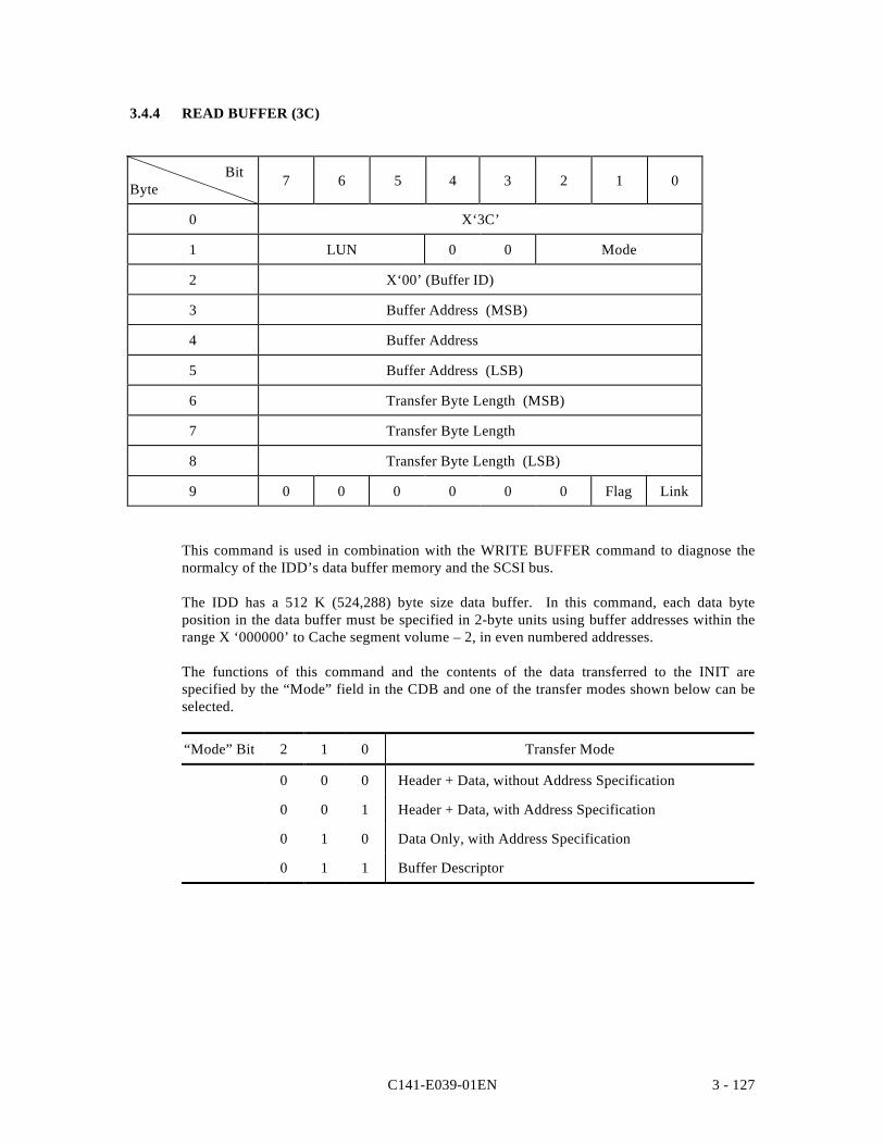
C141-E039-01EN 3 - 127
3.4.4 READ BUFFER (3C)
BitByte 7 6 5 4 3 2 1 0
0 X‘3C’
1 LUN 0 0 Mode
2 X‘00’ (Buffer ID)
3 Buffer Address (MSB)
4 Buffer Address
5 Buffer Address (LSB)
6 Transfer Byte Length (MSB)
7 Transfer Byte Length
8 Transfer Byte Length (LSB)
9 0 0 0 0 0 0 Flag Link
This command is used in combination with the WRITE BUFFER command to diagnose thenormalcy of the IDD’s data buffer memory and the SCSI bus.
The IDD has a 512 K (524,288) byte size data buffer. In this command, each data byteposition in the data buffer must be specified in 2-byte units using buffer addresses within therange X ‘000000’ to Cache segment volume – 2, in even numbered addresses.
The functions of this command and the contents of the data transferred to the INIT arespecified by the “Mode” field in the CDB and one of the transfer modes shown below can beselected.
“Mode” Bit 2 1 0 Transfer Mode
0 0 0 Header + Data, without Address Specification
0 0 1 Header + Data, with Address Specification
0 1 0 Data Only, with Address Specification
0 1 1 Buffer Descriptor
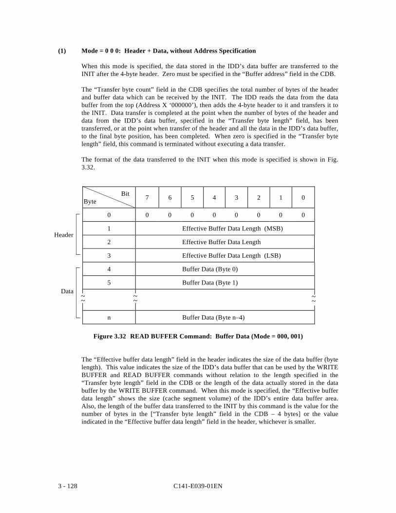
C141-E039-01EN3 - 128
(1) Mode = 0 0 0: Header + Data, without Address Specification
When this mode is specified, the data stored in the IDD’s data buffer are transferred to theINIT after the 4-byte header. Zero must be specified in the “Buffer address” field in the CDB.
The “Transfer byte count” field in the CDB specifies the total number of bytes of the headerand buffer data which can be received by the INIT. The IDD reads the data from the databuffer from the top (Address X ‘000000’), then adds the 4-byte header to it and transfers it tothe INIT. Data transfer is completed at the point when the number of bytes of the header anddata from the IDD’s data buffer, specified in the “Transfer byte length” field, has beentransferred, or at the point when transfer of the header and all the data in the IDD’s data buffer,to the final byte position, has been completed. When zero is specified in the “Transfer bytelength” field, this command is terminated without executing a data transfer.
The format of the data transferred to the INIT when this mode is specified is shown in Fig.3.32.
BitByte 7 6 5 4 3 2 1 0
0 0 0 0 0 0 0 0 0
1 Effective Buffer Data Length (MSB)
2 Effective Buffer Data Length
3 Effective Buffer Data Length (LSB)
4 Buffer Data (Byte 0)
5 Buffer Data (Byte 1)
n Buffer Data (Byte n–4)
Figure 3.32 READ BUFFER Command: Buffer Data (Mode = 000, 001)
The “Effective buffer data length” field in the header indicates the size of the data buffer (bytelength). This value indicates the size of the IDD’s data buffer that can be used by the WRITEBUFFER and READ BUFFER commands without relation to the length specified in the“Transfer byte length” field in the CDB or the length of the data actually stored in the databuffer by the WRITE BUFFER command. When this mode is specified, the “Effective bufferdata length” shows the size (cache segment volume) of the IDD’s entire data buffer area.Also, the length of the buffer data transferred to the INIT by this command is the value for thenumber of bytes in the [“Transfer byte length” field in the CDB – 4 bytes] or the valueindicated in the “Effective buffer data length” field in the header, whichever is smaller.
~~ ~~~~
Header
Data
C141-E039-01EN 3 - 129
(2) Mode = 0, 0, 1: Header + Data, with Address Specification
The format of the data transferred to the INIT when this mode is specified is the same as theformat of the data in the case of Mode = 0, 0, 0, with the data stored in the IDD’s data buffertransferred to the INIT following the 4-byte header. In this mode, the address in the databuffer can be specified in the “Buffer address” field in the CDB.
The “Transfer byte length” field in the CDB specifies the total number of bytes of header andbuffer data that can be received by the INIT. The IDD reads the data from the data bufferbeginning from the byte position in the data buffer specified in the “Buffer address” field ofthe CDB and continuing in order, then adds the 4-byte header to it and transfers it to the INIT.Data transfer is completed at the point when the number of bytes of the header and data fromthe IDD’s data buffer, specified in the “Transfer byte length” field, has been transferred, or atthe point when transfer of the header and all the data in the IDD’s data buffer, to the final byteposition, has been completed. When zero is specified in the “Transfer byte length” field, thiscommand is terminated without executing a data transfer.
The format and contents of the 4-byte header transferred in this mode are the same as in thecase of Mode = 0, 0, 0. However, the “Effective buffer data length” field in the headerindicates the size (byte length) of the data from the byte position in the data buffer specified inthe “Buffer address” field in the CDB to the final byte position in the data buffer, includingthat byte. Also, the length of the buffer data transferred to the INIT by this command is thevalue for the number of bytes in the [“Transfer byte length” field in the CDB – 4 bytes] or thevalue indicated in the “Effective buffer data length” in the header, whichever is smaller.
(3) Mode = 0, 1, 0: Data Only, with Address Specification
The data transferred to the INIT when this mode is specified is only the data which the IDDreads from the data buffer. The header is not transferred as it is in Mode = 0,0,0 and Mode =0,0,1. In this mode, address in the data buffer can be specified in the “Buffer address” field inthe CDB.
The “Transfer byte length” field in the CDB specifies the total number of bytes of buffer datathat can be received by the INIT. The IDD reads the data in order beginning from the byteposition in the data buffer specified in the “Buffer address” field and transfers it to the INIT.Data transfer is completed at the point when the number of bytes of buffer data specified in the“Transfer byte length” field has been completed or transfer of the buffer data to the final byteposition of the IDD’s data buffer is completed. When zero is specified in the “Transfer bytelength” field, this command is terminated without executing a data transfer.
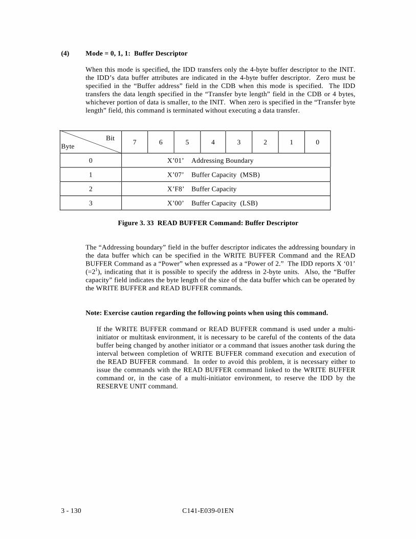
C141-E039-01EN3 - 130
(4) Mode = 0, 1, 1: Buffer Descriptor
When this mode is specified, the IDD transfers only the 4-byte buffer descriptor to the INIT.the IDD’s data buffer attributes are indicated in the 4-byte buffer descriptor. Zero must bespecified in the “Buffer address” field in the CDB when this mode is specified. The IDDtransfers the data length specified in the “Transfer byte length” field in the CDB or 4 bytes,whichever portion of data is smaller, to the INIT. When zero is specified in the “Transfer bytelength” field, this command is terminated without executing a data transfer.
BitByte 7 6 5 4 3 2 1 0
0 X’01’ Addressing Boundary
1 X’07’ Buffer Capacity (MSB)
2 X’F8’ Buffer Capacity
3 X’00’ Buffer Capacity (LSB)
Figure 3. 33 READ BUFFER Command: Buffer Descriptor
The “Addressing boundary” field in the buffer descriptor indicates the addressing boundary inthe data buffer which can be specified in the WRITE BUFFER Command and the READBUFFER Command as a “Power” when expressed as a “Power of 2.” The IDD reports X ‘01’(=21), indicating that it is possible to specify the address in 2-byte units. Also, the “Buffercapacity” field indicates the byte length of the size of the data buffer which can be operated bythe WRITE BUFFER and READ BUFFER commands.
Note: Exercise caution regarding the following points when using this command.
If the WRITE BUFFER command or READ BUFFER command is used under a multi-initiator or multitask environment, it is necessary to be careful of the contents of the databuffer being changed by another initiator or a command that issues another task during theinterval between completion of WRITE BUFFER command execution and execution ofthe READ BUFFER command. In order to avoid this problem, it is necessary either toissue the commands with the READ BUFFER command linked to the WRITE BUFFERcommand or, in the case of a multi-initiator environment, to reserve the IDD by theRESERVE UNIT command.
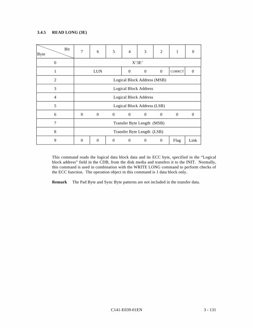
C141-E039-01EN 3 - 131
3.4.5 READ LONG (3E)
BitByte 7 6 5 4 3 2 1 0
0 X‘3E’
1 LUN 0 0 0 CORRCT 0
2 Logical Block Address (MSB)
3 Logical Block Address
4 Logical Block Address
5 Logical Block Address (LSB)
6 0 0 0 0 0 0 0 0
7 Transfer Byte Length (MSB)
8 Transfer Byte Length (LSB)
9 0 0 0 0 0 0 Flag Link
This command reads the logical data block data and its ECC byte, specified in the “Logicalblock address” field in the CDB, from the disk media and transfers it to the INIT. Normally,this command is used in combination with the WRITE LONG command to perform checks ofthe ECC function. The operation object in this command is 1 data block only.
Remark The Pad Byte and Sync Byte patterns are not included in the transfer data.
C141-E039-01EN3 - 132
When “0” is specified in bit 1 of CDB byte 1, the “CORRCT (Corrected)” bit, the IDD doesnot implement ECC correction processing of data read from the disk media. When “1” isspecified in the “CORRCT (Corrected)” bit, data errors that can be corrected by ECC aretransferred to the INIT after being corrected in the IDD’s data buffer. This IDD does notsupport his function.
The “Logical byte length” field in the CDB indicates the number of bytes of data transferred tothe INIT by this command and if 1 logical data block is configured from n logical sectors (n:1, 2, 4), it is necessary to specify a [Logical data block length + n x 16] byte length.
When the “Transfer byte length” specifies zero, this command executes a seek operation of thecylinder/track existing in the logical data block which is specified in the “Logical blockaddress” field in the CDB., then is terminated without data being transferred to the INIT.
When a length (other than zero) which does not match the data format on the disk media isspecified in the “Transfer byte length” field in the CDB, this command is terminated with aCHECK CONDITION status without executing a data transfer to the INIT. At this time, thesense data indicate the following contents and the INIT can determine the correct “Transferbyte length” from their contents.
• Sense Key : 05 = ILLEGAL REQUEST• Sense Code/Sub-sense Code : 24-00 = Invalid field in CDB• “VALID” Bit : “1”• “ILI” bit : “1”• Information Field : (“Transfer byte length in the CDB) – (Original “Transfer byte length”)
Remark The calculation formula for the information field expresses 1 logical data block asn physical sectors, and when negative, as a complement of 2.
Error recovery processing during execution of this command is in accordance with thespecifications in (Page code 1: Read/Write Error Recovery Parameter, Page code 21:Additional error recovery parameters).
• The ARRE flag and the DTE flag are not applied.• The TB flag is treated as if “1” was specified.
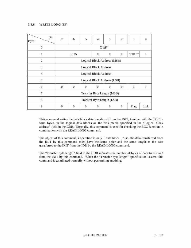
C141-E039-01EN 3 - 133
3.4.6 WRITE LONG (3F)
BitByte 7 6 5 4 3 2 1 0
0 X‘3F’
1 LUN 0 0 0 CORRCT 0
2 Logical Block Address (MSB)
3 Logical Block Address
4 Logical Block Address
5 Logical Block Address (LSB)
6 0 0 0 0 0 0 0 0
7 Transfer Byte Length (MSB)
8 Transfer Byte Length (LSB)
9 0 0 0 0 0 0 Flag Link
This command writes the data block data transferred from the INIT, together with the ECC toform bytes, in the logical data blocks on the disk media specified in the “Logical blockaddress” field in the CDB. Normally, this command is used for checking the ECC function incombination with the READ LONG command.
The object of this command’s operation is only 1 data block. Also, the data transferred fromthe INIT by this command must have the same order and the same length as the datatransferred to the INIT from the IDD by the READ LONG command.
The “Transfer byte length” field in the CDB indicates the number of bytes of data transferredfrom the INIT by this command. When the “Transfer byte length” specification is zero, thiscommand is terminated normally without performing anything.
C141-E039-01EN3 - 134
If a value specifying a length (other than zero) that does not match the data format on the diskmedia is specified in the “Transfer byte length” field in the CDB, that command is terminatedwith a CHECK CONDITION status without data being transferred to the INIT. The sense dataat this time indicate the following contents and the INIT can determine the correct “Transferbyte length” from their contents.
• Sense Key : 05 = ILLEGAL REQUEST• Sense Code/Sub-sense Code : 24-00 = Invalid field in CDB• “VALID” Bit : “1”• “ILI” bit : “1”• Information Field : (“Transfer byte length in the CDB) – (Original “Transfer byte length”)
Remark The calculation formula for the information field expresses 1 logical data block as nphysical sectors and n sub-sectors, and when negative, as a complement of 2.
Error recovery processing during execution of this command is performed in accordance withthe specifications in the MODE SELECT parameters (Page code 1: Read/Write ErrorRecovery Parameter, Page Code 21: Additional Error Recovery Parameter, but the AWREflag and DTE flag are not applied.
C141-E039-01EN 4 - 1
CHAPTER 4 SENSE DATA ERROR RECOVERY METHODS
4.1 Sense Data
4.2 INIT Error Recovery Methods (Recommended)
4.3 Disk Drive Error Recovery Methods
In this chapter, the configuration and contents of sense data reported to the INIT (initiator) when anerror occurs, etc., key information for interpreting error states, recommended procedures for errorrecovery processing that should be executed by software in the INIT and error recovery processingexecuted internally by the IDD are described. Furthermore, see Chapter 3, “SCSI Bus Error RecoveryProcessing” in the “SCSI Physical Interface Specifications” concerning recovery processing for errorsdetected in operations on the SCSI bus.
4.1 Sense Data
When the IDD reports a CHECK CONDITION status, or in cases when some fatal error isdetected in connection with the SCSI bus, and as a result, the command that is currently beingexecuted, or the commands in the stack are cleared, it generates sense data for the INIT thatissued that command. The INIT can fetch the sense data by issuing a REQUEST SENSEcommand.
4.1.1 Sense Data Format
The IDD’s sense data is in the so-called “Expanded Sense Data” format. The expanded sensedata format supported by the IDD is shown in Fig. 4.1.
Notes:
1. In the SCSI specifications, each device is permitted to define whatever it chooses afterbyte 18 of the expanded sense data, and the length and format differ for each device.The length of expanded sense data is displayed in the sense data, so by analyzing thesense data which it receives, the INIT can know its effective length.
2. In the REQUEST SENSE command, even if a “Transfer byte” length that is shorterthan the length of the sense data supported by the device which is the object of thecommand, the command will terminate normally, but in that case, some of the sensedata only will be received and the remaining information will be lost. Sufficientcaution should be exercised with regard to the devices connected to the INIT and allthe sense data of those devices should be read.
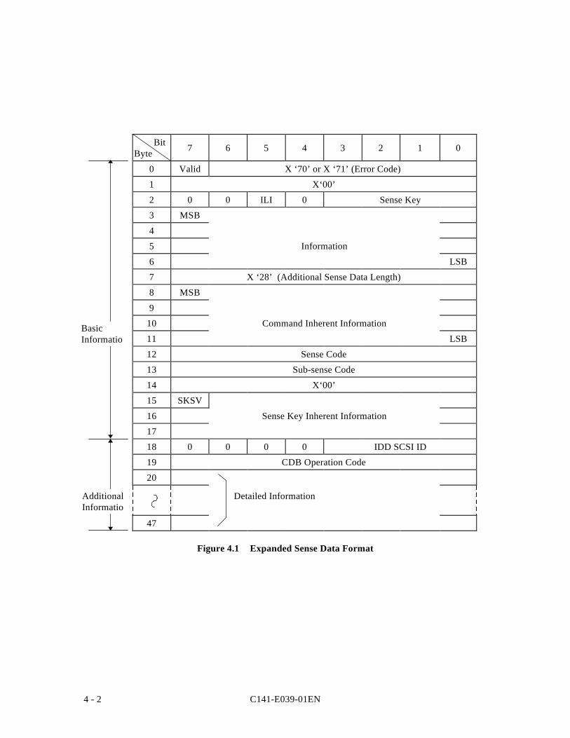
C141-E039-01EN4 - 2
BitByte 7 6 5 4 3 2 1 0
0 Valid X ‘70’ or X ‘71’ (Error Code)
1 X‘00’
2 0 0 ILI 0 Sense Key
3 MSB
4
5 Information
6 LSB
7 X ‘28’ (Additional Sense Data Length)
8 MSB
9
10 Command Inherent Information
11 LSB
12 Sense Code
13 Sub-sense Code
14 X‘00’
15 SKSV
16 Sense Key Inherent Information
17
18 0 0 0 0 IDD SCSI ID
19 CDB Operation Code
20
47
Figure 4.1 Expanded Sense Data Format
Detailed Information
BasicInformatio
AdditionalInformatio
C141-E039-01EN 4 - 3
4.1.2 Sense Data Basic Information
Bytes 0 to 17 of the sense data are basic information which show the contents of the error thathas occurred. The INIT can know the contents of the error and the key information that isnecessary for recovery processing by analyzing this basic information. Each field and themeanings of bits in the sense data basic information are explained below.
(1) Valid
When this bit is “1,” it indicates that the values shown in the information field (bytes 3 to 6)are valid. On the other hand, when this bit is “0”, it indicates that the information field doesnot contain valid information.
(2) Error Code
This field shows the format and type of sense data. The IDD always displays X ‘70’ (currenterror) or X ‘71’ (deferred error), which has the meaning “Expanded Sense Data Format” in thisfield.
(3) ILI (incorrect length indicator)
When this bit is “1,” it indicates that the transfer byte length requested in the command did notcoincide with the data block length on the disk media. In the IDD, the only commands that itreports “1” in this bit for are the READ LONG command and the WRITE LONG command.For details, refer to the descriptions of these commands (item 3.4.5 and item 3.4.6).
(4) Sense Key
This field shows the cause of the sense data being generated. More details reasons areindicated in the sense code field (Byte 12) and the sub-sense code field (Byte 13). Table 4.1shows a list of the meanings of sense keys.
(5) Information
This field shows information related to the error that has been detected and is valid only whenthe Valid bit is “1.” Depending on the command where the error occurred, additionalinformation other than the information in this field may be indicated in the command inherentinformation field. The information shown in this field has the following meanings dependingon the value of the “ILI” bit.
a) When the “ILI” bit is “0,” the logical block address of the data block where the erroroccurred is indicated.
b) When the “ILI” bit is “1,” the difference between the transfer byte length requested by thecommand and the actual data block length on the disk media is indicated. If the difference is aminus value, (if the request transfer byte count is smaller), it is expressed as a complement of 2.In the IDD, only the READ LONG command and the WRITE LONG command display thisinformation. For details, see the descriptions of these commands (item 3.4.5 and item 3.4.6).
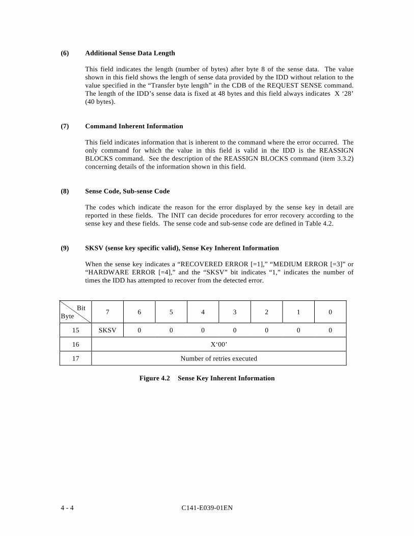
C141-E039-01EN4 - 4
(6) Additional Sense Data Length
This field indicates the length (number of bytes) after byte 8 of the sense data. The valueshown in this field shows the length of sense data provided by the IDD without relation to thevalue specified in the “Transfer byte length” in the CDB of the REQUEST SENSE command.The length of the IDD’s sense data is fixed at 48 bytes and this field always indicates X ‘28’(40 bytes).
(7) Command Inherent Information
This field indicates information that is inherent to the command where the error occurred. Theonly command for which the value in this field is valid in the IDD is the REASSIGNBLOCKS command. See the description of the REASSIGN BLOCKS command (item 3.3.2)concerning details of the information shown in this field.
(8) Sense Code, Sub-sense Code
The codes which indicate the reason for the error displayed by the sense key in detail arereported in these fields. The INIT can decide procedures for error recovery according to thesense key and these fields. The sense code and sub-sense code are defined in Table 4.2.
(9) SKSV (sense key specific valid), Sense Key Inherent Information
When the sense key indicates a “RECOVERED ERROR [=1],” “MEDIUM ERROR [=3]” or“HARDWARE ERROR [=4],” and the “SKSV” bit indicates “1,” indicates the number oftimes the IDD has attempted to recover from the detected error.
BitByte 7 6 5 4 3 2 1 0
15 SKSV 0 0 0 0 0 0 0
16 X‘00’
17 Number of retries executed
Figure 4.2 Sense Key Inherent Information
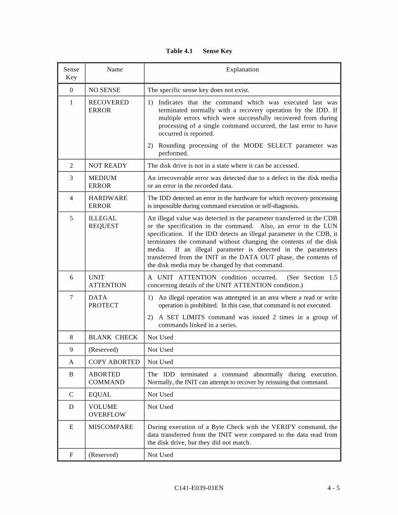
C141-E039-01EN 4 - 5
Table 4.1 Sense Key
SenseKey
Name Explanation
0 NO SENSE The specific sense key does not exist.
1 RECOVEREDERROR
1) Indicates that the command which was executed last wasterminated normally with a recovery operation by the IDD. Ifmultiple errors which were successfully recovered from duringprocessing of a single command occurred, the last error to haveoccurred is reported.
2) Rounding processing of the MODE SELECT parameter wasperformed.
2 NOT READY The disk drive is not in a state where it can be accessed.
3 MEDIUMERROR
An irrecoverable error was detected due to a defect in the disk mediaor an error in the recorded data.
4 HARDWAREERROR
The IDD detected an error in the hardware for which recovery processingis impossible during command execution or self-diagnosis.
5 ILLEGALREQUEST
An illegal value was detected in the parameter transferred in the CDBor the specification in the command. Also, an error in the LUNspecification. If the IDD detects an illegal parameter in the CDB, itterminates the command without changing the contents of the diskmedia. If an illegal parameter is detected in the parameterstransferred from the INIT in the DATA OUT phase, the contents ofthe disk media may be changed by that command.
6 UNITATTENTION
A UNIT ATTENTION condition occurred. (See Section 1.5concerning details of the UNIT ATTENTION condition.)
7 DATAPROTECT
1) An illegal operation was attempted in an area where a read or writeoperation is prohibited. In this case, that command is not executed.
2) A SET LIMITS command was issued 2 times in a group ofcommands linked in a series.
8 BLANK CHECK Not Used
9 (Reserved) Not Used
A COPY ABORTED Not Used
B ABORTEDCOMMAND
The IDD terminated a command abnormally during execution.Normally, the INIT can attempt to recover by reissuing that command.
C EQUAL Not Used
D VOLUMEOVERFLOW
Not Used
E MISCOMPARE During execution of a Byte Check with the VERIFY command, thedata transferred from the INIT were compared to the data read fromthe disk drive, but they did not match.
F (Reserved) Not Used
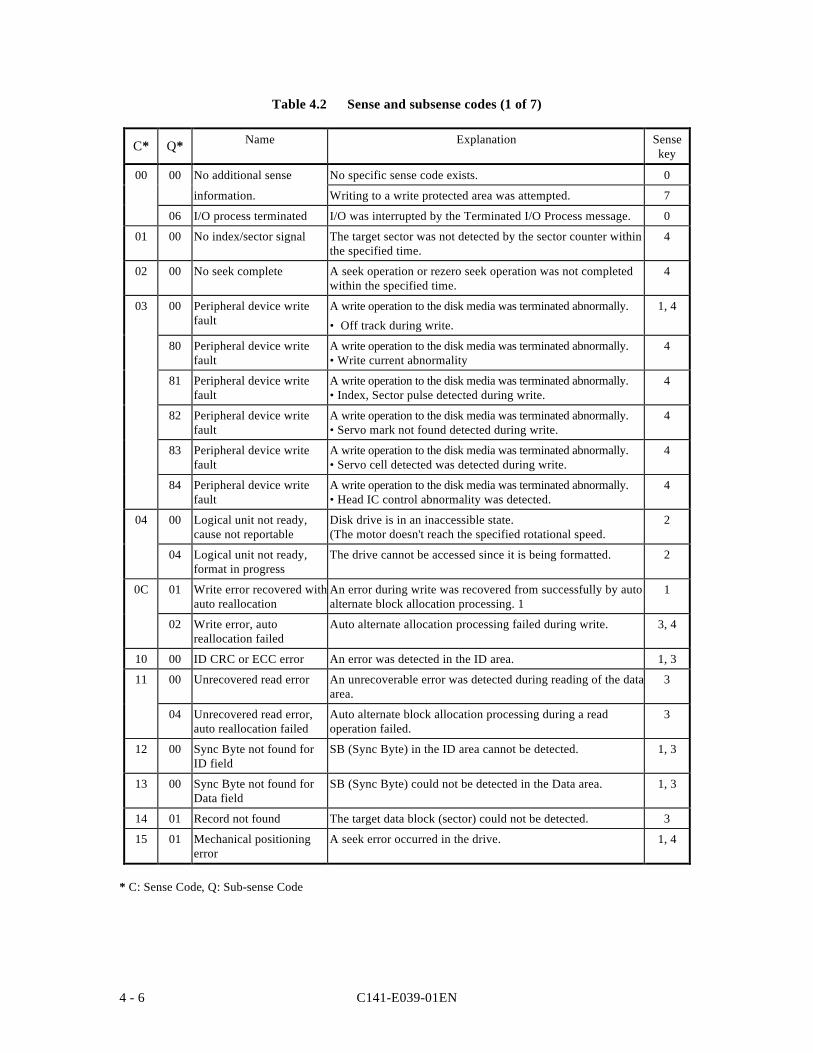
C141-E039-01EN4 - 6
Table 4.2 Sense and subsense codes (1 of 7)
C* Q* Name Explanation Sensekey
00 00 No additional sense No specific sense code exists. 0
information. Writing to a write protected area was attempted. 7
06 I/O process terminated I/O was interrupted by the Terminated I/O Process message. 0
01 00 No index/sector signal The target sector was not detected by the sector counter withinthe specified time.
4
02 00 No seek complete A seek operation or rezero seek operation was not completedwithin the specified time.
4
03 00 Peripheral device writefault
A write operation to the disk media was terminated abnormally.
• Off track during write.
1, 4
80 Peripheral device writefault
A write operation to the disk media was terminated abnormally.• Write current abnormality
4
81 Peripheral device writefault
A write operation to the disk media was terminated abnormally.• Index, Sector pulse detected during write.
4
82 Peripheral device writefault
A write operation to the disk media was terminated abnormally.• Servo mark not found detected during write.
4
83 Peripheral device writefault
A write operation to the disk media was terminated abnormally.• Servo cell detected was detected during write.
4
84 Peripheral device writefault
A write operation to the disk media was terminated abnormally.• Head IC control abnormality was detected.
4
04 00 Logical unit not ready,cause not reportable
Disk drive is in an inaccessible state.(The motor doesn't reach the specified rotational speed.
2
04 Logical unit not ready,format in progress
The drive cannot be accessed since it is being formatted. 2
0C 01 Write error recovered withauto reallocation
An error during write was recovered from successfully by autoalternate block allocation processing. 1
1
02 Write error, autoreallocation failed
Auto alternate allocation processing failed during write. 3, 4
10 00 ID CRC or ECC error An error was detected in the ID area. 1, 3
11 00 Unrecovered read error An unrecoverable error was detected during reading of the dataarea.
3
04 Unrecovered read error,auto reallocation failed
Auto alternate block allocation processing during a readoperation failed.
3
12 00 Sync Byte not found forID field
SB (Sync Byte) in the ID area cannot be detected. 1, 3
13 00 Sync Byte not found forData field
SB (Sync Byte) could not be detected in the Data area. 1, 3
14 01 Record not found The target data block (sector) could not be detected. 3
15 01 Mechanical positioningerror
A seek error occurred in the drive. 1, 4
* C: Sense Code, Q: Sub-sense Code

C141-E039-01EN 4 - 7
Table 4.2 Sense and subsense codes (2 of 7)
C* Q* Name Explanation Sensekey
15 01 Mechanical positioning error A seek error occurred in the drive. 1, 4
02 Positioning error detectedby read of medium
The cylinder address in the ID area did not match. 1, 4
80 Off-track detected Went off-track while it was on track. 4
81 No on track after SKC On track could not be detected after seek wascompleted.
4
F0 Calibration failed Calibration was terminated with an error. 1, 4
17 01 Recovered data with retries A data error was recovered from by reading wasretried.
1
18 00 Recovered data with ECCapplied
A data error was recovered from immediately byECC correction.
1
01 Recovered data with ECC& retries applied
A data error was recovered from by ECC correctionafter reading was retried.
1
02 Recovered data with ECCand/or retries, data auto-reallocated
A data error was recovered by ECC correction andauto alternate block allocation was applied.
1
80 Recovered data with ECCand/or retries, re-writeapplied
A data error was recovered by ECC correction andthe same block was recovered by rewriting.
1
19 00 Defect list error An error was detected during reading of defectcontrol information.
3
02 Defect list error in primarylist
An error was detected during reading of the defectlist (P List).
3
03 Defect list error in grownlist
An error was detected during reading of the defectlist (G List).
3
04 SA Control code readerror
An error was detected during reading of the SAupdate control code.
3
05 Defect list error inmanagement list
An error was detected during reading of the defectcontrol table.
3
06 Cylinder skew table readerror
An error was detected during reading of the cylinderskew table.
3
80 Log information read error An error was detected during reading of statisticalinformation.
3
81 Log information writeerror
A write error was detected during writing ofstatistical information.
3
82 Mode select SA read error An error was detected during reading of SAinformation (Mode select parameter).
3
19 83 Mode select SA write error An error was detected during writing of SAinformation (Mode select parameter).
3
* C: Sense Code, Q: Sub-sense Code
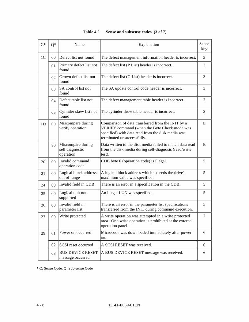
C141-E039-01EN4 - 8
Table 4.2 Sense and subsense codes (3 of 7)
C* Q* Name Explanation Sensekey
1C 00 Defect list not found The defect management information header is incorrect. 3
01 Primary defect list notfound
The defect list (P List) header is incorrect. 3
02 Grown defect list notfound
The defect list (G List) header is incorrect. 3
03 SA control list notfound
The SA update control code header is incorrect. 3
04 Defect table list notfound
The defect management table header is incorrect. 3
05 Cylinder skew list notfound
The cylinder skew table header is incorrect. 3
1D 00 Miscompare duringverify operation
Comparison of data transferred from the INIT by aVERIFY command (when the Byte Check mode wasspecified) with data read from the disk media wasterminated unsuccessfully.
E
80 Miscompare duringself diagnosticoperation
Data written to the disk media failed to match data readfrom the disk media during self-diagnosis (read/writetest).
E
20 00 Invalid commandoperation code
CDB byte 0 (operation code) is illegal. 5
21 00 Logical block addressout of range
A logical block address which exceeds the drive'smaximum value was specified.
5
24 00 Invalid field in CDB There is an error in a specification in the CDB. 5
25 00 Logical unit notsupported
An illegal LUN was specified. 5
26 00 Invalid field inparameter list
There is an error in the parameter list specificationstransferred from the INIT during command execution.
5
27 00 Write protected A write operation was attempted in a write protectedarea. Or a write operation is prohibited at the externaloperation panel.
7
29 01 Power on occurred Microcode was downloaded immediately after poweron.
6
02 SCSI reset occurred A SCSI RESET was received. 6
03 BUS DEVICE RESETmessage occurred
A BUS DEVICE RESET message was received. 6
* C: Sense Code, Q: Sub-sense Code
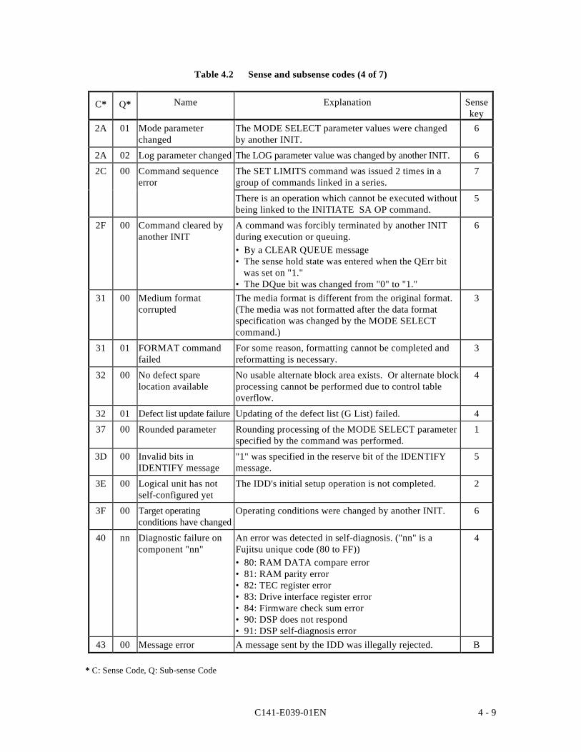
C141-E039-01EN 4 - 9
Table 4.2 Sense and subsense codes (4 of 7)
C* Q* Name Explanation Sensekey
2A 01 Mode parameterchanged
The MODE SELECT parameter values were changedby another INIT.
6
2A 02 Log parameter changed The LOG parameter value was changed by another INIT. 6
2C 00 Command sequenceerror
The SET LIMITS command was issued 2 times in agroup of commands linked in a series.
7
There is an operation which cannot be executed withoutbeing linked to the INITIATE SA OP command.
5
2F 00 Command cleared byanother INIT
A command was forcibly terminated by another INITduring execution or queuing.• By a CLEAR QUEUE message• The sense hold state was entered when the QErr bit
was set on "1."• The DQue bit was changed from "0" to "1."
6
31 00 Medium formatcorrupted
The media format is different from the original format.(The media was not formatted after the data formatspecification was changed by the MODE SELECTcommand.)
3
31 01 FORMAT commandfailed
For some reason, formatting cannot be completed andreformatting is necessary.
3
32 00 No defect sparelocation available
No usable alternate block area exists. Or alternate blockprocessing cannot be performed due to control tableoverflow.
4
32 01 Defect list update failure Updating of the defect list (G List) failed. 4
37 00 Rounded parameter Rounding processing of the MODE SELECT parameterspecified by the command was performed.
1
3D 00 Invalid bits inIDENTIFY message
"1" was specified in the reserve bit of the IDENTIFYmessage.
5
3E 00 Logical unit has notself-configured yet
The IDD's initial setup operation is not completed. 2
3F 00 Target operatingconditions have changed
Operating conditions were changed by another INIT. 6
40 nn Diagnostic failure oncomponent "nn"
An error was detected in self-diagnosis. ("nn" is aFujitsu unique code (80 to FF))• 80: RAM DATA compare error• 81: RAM parity error• 82: TEC register error• 83: Drive interface register error• 84: Firmware check sum error• 90: DSP does not respond• 91: DSP self-diagnosis error
4
43 00 Message error A message sent by the IDD was illegally rejected. B
* C: Sense Code, Q: Sub-sense Code
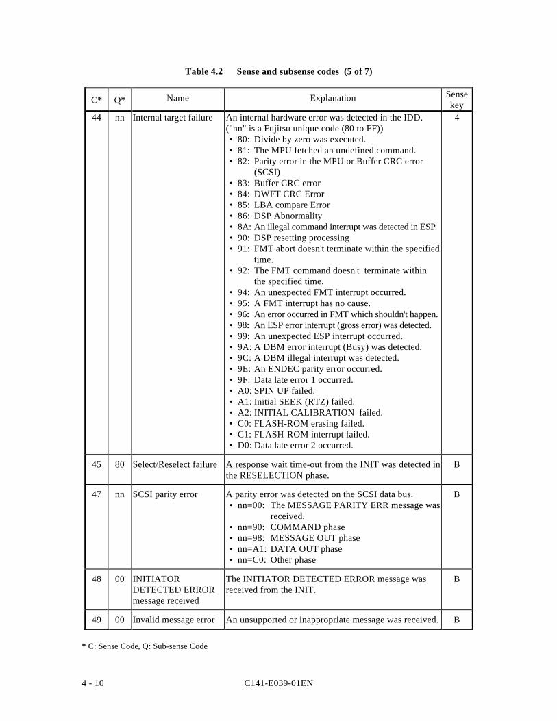
C141-E039-01EN4 - 10
Table 4.2 Sense and subsense codes (5 of 7)
C* Q* Name Explanation Sensekey
44 nn Internal target failure An internal hardware error was detected in the IDD.("nn" is a Fujitsu unique code (80 to FF))• 80: Divide by zero was executed.• 81: The MPU fetched an undefined command.• 82: Parity error in the MPU or Buffer CRC error
(SCSI)• 83: Buffer CRC error• 84: DWFT CRC Error• 85: LBA compare Error• 86: DSP Abnormality• 8A: An illegal command interrupt was detected in ESP• 90: DSP resetting processing• 91: FMT abort doesn't terminate within the specified
time.• 92: The FMT command doesn't terminate within
the specified time.• 94: An unexpected FMT interrupt occurred.• 95: A FMT interrupt has no cause.• 96: An error occurred in FMT which shouldn't happen.• 98: An ESP error interrupt (gross error) was detected.• 99: An unexpected ESP interrupt occurred.• 9A: A DBM error interrupt (Busy) was detected.• 9C: A DBM illegal interrupt was detected. • 9E: An ENDEC parity error occurred.• 9F: Data late error 1 occurred.• A0: SPIN UP failed.• A1: Initial SEEK (RTZ) failed.• A2: INITIAL CALIBRATION failed.• C0: FLASH-ROM erasing failed.• C1: FLASH-ROM interrupt failed.• D0: Data late error 2 occurred.
4
45 80 Select/Reselect failure A response wait time-out from the INIT was detected inthe RESELECTION phase.
B
47 nn SCSI parity error A parity error was detected on the SCSI data bus.• nn=00: The MESSAGE PARITY ERR message was
received.• nn=90: COMMAND phase• nn=98: MESSAGE OUT phase• nn=A1: DATA OUT phase• nn=C0: Other phase
B
48 00 INITIATORDETECTED ERRORmessage received
The INITIATOR DETECTED ERROR message wasreceived from the INIT.
B
49 00 Invalid message error An unsupported or inappropriate message was received. B
* C: Sense Code, Q: Sub-sense Code
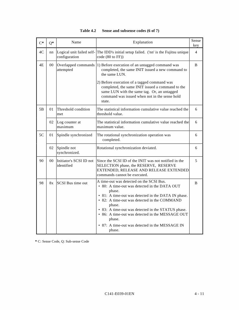
C141-E039-01EN 4 - 11
Table 4.2 Sense and subsense codes (6 of 7)
C* Q* Name Explanation Sensekey
4C nn Logical unit failed self-configuration
The IDD's initial setup failed. ('nn' is the Fujitsu uniquecode (80 to FF))
4
4E 00 Overlapped commandsattempted
1) Before execution of an untagged command wascompleted, the same INIT issued a new command tothe same LUN.
2) Before execution of a tagged command wascompleted, the same INIT issued a command to thesame LUN with the same tag. Or, an untaggedcommand was issued when not in the sense holdstate.
B
5B 01 Threshold conditionmet
The statistical information cumulative value reached thethreshold value.
6
02 Log counter atmaximum
The statistical information cumulative value reached themaximum value.
6
5C 01 Spindle synchronized The rotational synchronization operation wascompleted.
6
02 Spindle notsynchronized.
Rotational synchronization deviated. 6
90 00 Initiator's SCSI ID notidentified
Since the SCSI ID of the INIT was not notified in theSELECTION phase, the RESERVE, RESERVEEXTENDED, RELEASE AND RELEASE EXTENDEDcommands cannot be executed.
5
98 8x SCSI Bus time out A time-out was detected on the SCSI Bus.• 80: A time-out was detected in the DATA OUT
phase.• 81: A time-out was detected in the DATA IN phase.• 82: A time-out was detected in the COMMAND
phase.• 83: A time-out was detected in the STATUS phase.• 86: A time-out was detected in the MESSAGE OUT
phase.
• 87: A time-out was detected in the MESSAGE INphase.
B
* C: Sense Code, Q: Sub-sense Code
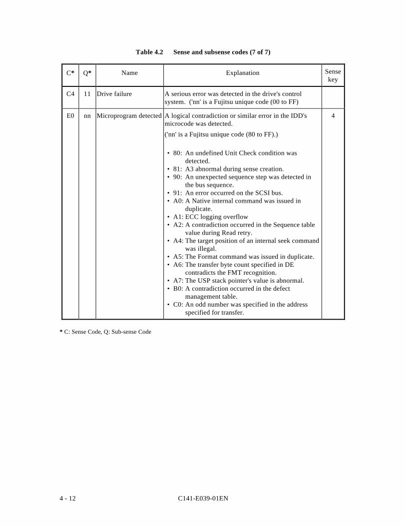
C141-E039-01EN4 - 12
Table 4.2 Sense and subsense codes (7 of 7)
C* Q* Name Explanation Sensekey
C4 11 Drive failure A serious error was detected in the drive's controlsystem. ('nn' is a Fujitsu unique code (00 to FF)
E0 nn Microprogram detected A logical contradiction or similar error in the IDD'smicrocode was detected.
('nn' is a Fujitsu unique code (80 to FF).)
• 80: An undefined Unit Check condition wasdetected.
• 81: A3 abnormal during sense creation.• 90: An unexpected sequence step was detected in
the bus sequence.• 91: An error occurred on the SCSI bus.• A0: A Native internal command was issued in
duplicate.• A1: ECC logging overflow• A2: A contradiction occurred in the Sequence table
value during Read retry.• A4: The target position of an internal seek command
was illegal.• A5: The Format command was issued in duplicate.• A6: The transfer byte count specified in DE
contradicts the FMT recognition.• A7: The USP stack pointer's value is abnormal.• B0: A contradiction occurred in the defect
management table.• C0: An odd number was specified in the address
specified for transfer.
4
* C: Sense Code, Q: Sub-sense Code
C141-E039-01EN 4 - 13
4.1.3 Sense Data Additional Information
Bytes 18 to 47 of sense data are defined as a Fujitsu unique field, and indicate the additionalinformation which is explained below.
(1) IDD SCSI ID
This field shows the SCSI ID of the very IDD which generated the sense data.
(2) CDB Operation Code
This field indicates the operation code (the value in the first byte of the CDB) of the commandwhere the error occurred. When sense data are generated without relation to the INIT issuing acommand, this field shows zero.
(3) Detailed Information
The information displayed in bytes 20 to 47 of sense data is information defined by Fujitsu forthe specific product for the purpose of analyzing trouble, and the contents of this informationare not made public. However, the user should present this information to the persons incharge at Fujitsu as troubleshooting and repair information collected in error logging (shownin item 4.3.3) of all the bytes in sense data, including this field.
4.2 INIT Error Recovery Methods (Recommended)
When a single command or a series of linked commands are not terminated with a GOODstatus or COMMAND COMPLETE message reported, the INIT should execute error recoveryprocessing corresponding to the state in which the command was terminated. Here, theprocedure for analyzing the command execution termination state and recommendedprocedures for error recovery processing executed by the INIT in accordance with the resultsare explained.
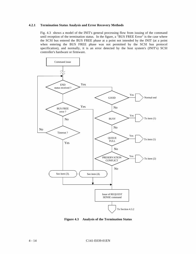
C141-E039-01EN4 - 14
4.2.1 Termination Status Analysis and Error Recovery Methods
Fig. 4.3 shows a model of the INIT's general processing flow from issuing of the commanduntil reception of the termination status. In the figure, a "BUS FREE Error" is the case wherethe SCSI bus entered the BUS FREE phase at a point not intended by the INIT (at a pointwhen entering the BUS FREE phase was not permitted by the SCSI bus protocolspecification), and normally, it is an error detected by the host system's (INIT's) SCSIcontroller's hardware or firmware.
ENDstatus received ?
BUS FREEerror ?
Timeout ?
See item (3). See item (4).
GOOD
BUSY
QUEUEFULL
Yes
Yes
Yes
Yes
No
No
No
No
Normal end
To item (1)
To item (1)
To item (2)
Yes
Yes
No
No
Yes
Command issue
PRESERVATIONCONFLICT
Issue of REQUESTSENSE command
To Section 4.3.2
Figure 4.3 Analysis of the Termination Status
C141-E039-01EN 4 - 15
(1) BUSY/QUEUE FULL Status
This status indicates that the IDD is currently executing processing of another command andthat a new command cannot be received. The INIT that receives this status can reissue theoriginal command.
Under a multi-initiator environment, when an INIT receives this status, the time until the IDDcan receive the next command depends on the operating state with other INITs, so ordinarily,it cannot be predicted. In such a case, it is necessary for the INIT that issued the command forwhich this status was received to repeatedly issue the command until it is accepted.
(2) RESERVATION CONFLICT Status
This status shows, under a multi-initiator environment, that the IDD is currently reserved byanother INIT, and cannot be used until that reserved status is released.
The period over which the reserved status continues should be managed by the system, butnormally, an INIT that receives this status reissues the original command after waiting anappropriate length of time. The wait time until a command is reissued is generally an inherentvalue of the system and it is necessary that consideration be given to the operating states of theother INITs in the system when deciding it.
Of the INIT which reserved the IDD falls into a state which it cannot recover from for anyreason before the reserved state is released, it will be impossible for other INITs to access theIDD because that reserved state will continue. In such a case, it is necessary for the INIT totake one of the following measures to forcibly release the reserved state and recover the accessright.
• BUS DEVICE RESET Message
• RESET Condition
C141-E039-01EN4 - 16
(3) Command Completion Wait Time-out
This error is a state where the completed status for a command is not reported within the timeexpected by the INIT that issued the command.
One cause of this error occurring, besides a malfunction of the IDD, is that the command wascleared by some method which the INIT that issued the command cannot clearly detect, suchas a BUS DEVICE RESET message, or the command was cleared when an unrecoverableerror was detected in reconnection processing executed by the IDD, etc. When this erroroccurs, the INIT should gather sense data by issuing the REQUEST SENSE command, thenjudge which recovery method to use based on the contents of the sense data (see item 4.2.2).
Not only does command execution time differ widely depending on the type and specifiedcontents of the command, but since it has an influence on the following factors, it is necessaryto give adequate consideration to these points when setting the monitoring time value at theINIT.
• Since the command stack feature exists (see Section 1.4), even if the IDD accepts acommand normally, if a command issued by another INIT is being executed, or if there areother commands in the stack, execution of the command is caused to wait until all theother commands have been processed. The execution wait time is dependent upon thetype of command issued by the other INITs and the contents of its specifications.
• If the IDD has executed error recovery processing (retried) for an error that occurred on theSCSI bus or in the disk drive, command completion time will be longer than normal.
(4) BUS FREE Error
This error occurs in the case that the SCSI bus enters the BUS FREE phase at a time when theINIT is not expecting it, during execution of a command on the SCSI bus. Even in caseswhere a RESET condition is generated by another SCSI device on the bus, the same stateoccurs, but the occurrence of an unexpected RESET condition should be processed as anabnormal state of the system.
The cause of this error is the occurrence of an unrecoverable error on the SCSI bus, theoccurrence of a serious protocol error, etc. For details concerning the causes of errors, seeChapter 3, "SCSI Bus Error Recovery Processing" in Chapter 3 of the "OEM Manual InterfaceSpecifications." When this error is detected, the INIT should issue the REQUEST SENSEcommand and gather sense data then judge the error recovery method according to thecontents of the sense data (see item 4.2.2).
4.2.2 Sense Data Analysis and Error Recovery Methods
The INIT can judge the procedure for error recovery by analyzing the contents of the sensedata fetched by the REQUEST SENSE command. Table 4.3 the classifications of errorinformation displayed in the sense data are shown and in Table 4.4, the procedures for errorrecovery recommended for the INIT to execute are shown. The error recovery procedurewhich can be executed by the INIT will differ depending on the system's condition, so theoptimum processing procedure should be selected for the user system with reference to thefollowing descriptions.
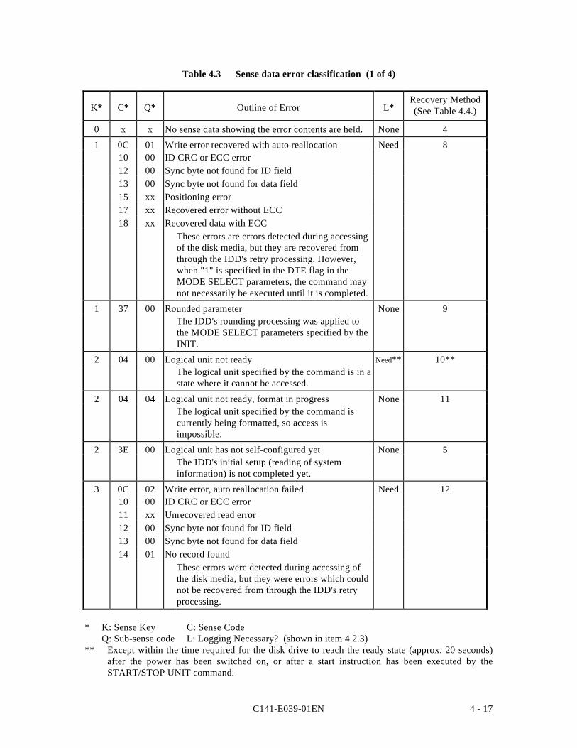
C141-E039-01EN 4 - 17
Table 4.3 Sense data error classification (1 of 4)
K* C* Q* Outline of Error L*Recovery Method(See Table 4.4.)
0 x x No sense data showing the error contents are held. None 4
1 0C 01 Write error recovered with auto reallocation Need 810 00 ID CRC or ECC error12 00 Sync byte not found for ID field13 00 Sync byte not found for data field15 xx Positioning error17 xx Recovered error without ECC18 xx Recovered data with ECC
These errors are errors detected during accessingof the disk media, but they are recovered fromthrough the IDD's retry processing. However,when "1" is specified in the DTE flag in theMODE SELECT parameters, the command maynot necessarily be executed until it is completed.
1 37 00 Rounded parameter None 9The IDD's rounding processing was applied tothe MODE SELECT parameters specified by theINIT.
2 04 00 Logical unit not ready Need** 10**The logical unit specified by the command is in astate where it cannot be accessed.
2 04 04 Logical unit not ready, format in progress None 11The logical unit specified by the command iscurrently being formatted, so access isimpossible.
2 3E 00 Logical unit has not self-configured yet None 5The IDD's initial setup (reading of systeminformation) is not completed yet.
3 0C 02 Write error, auto reallocation failed Need 1210 00 ID CRC or ECC error11 xx Unrecovered read error12 00 Sync byte not found for ID field13 00 Sync byte not found for data field14 01 No record found
These errors were detected during accessing ofthe disk media, but they were errors which couldnot be recovered from through the IDD's retryprocessing.
* K: Sense Key C: Sense CodeQ: Sub-sense code L: Logging Necessary? (shown in item 4.2.3)
** Except within the time required for the disk drive to reach the ready state (approx. 20 seconds)after the power has been switched on, or after a start instruction has been executed by theSTART/STOP UNIT command.
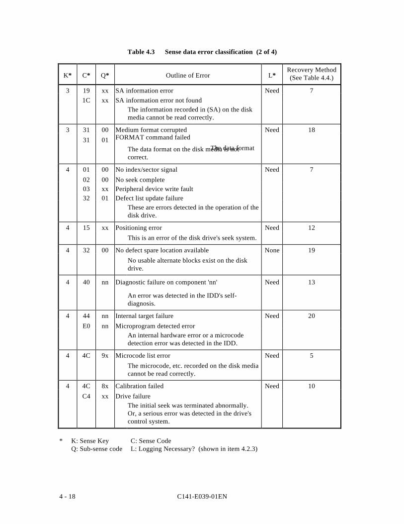
C141-E039-01EN4 - 18
Table 4.3 Sense data error classification (2 of 4)
K* C* Q* Outline of Error L*Recovery Method(See Table 4.4.)
3 19 xx SA information error Need 71C xx SA information error not found
The information recorded in (SA) on the diskmedia cannot be read correctly.
3 31 00 Medium format corrupted Need 1831 01 FORMAT command failed
The data formatThe data format on the disk media is notcorrect.
4 01 00 No index/sector signal Need 702 00 No seek complete03 xx Peripheral device write fault32 01 Defect list update failure
These are errors detected in the operation of thedisk drive.
4 15 xx Positioning error Need 12This is an error of the disk drive's seek system.
4 32 00 No defect spare location available None 19No usable alternate blocks exist on the diskdrive.
4 40 nn Diagnostic failure on component 'nn' Need 13
An error was detected in the IDD's self-diagnosis.
4 44 nn Internal target failure Need 20E0 nn Microprogram detected error
An internal hardware error or a microcodedetection error was detected in the IDD.
4 4C 9x Microcode list error Need 5The microcode, etc. recorded on the disk mediacannot be read correctly.
4 4C 8x Calibration failed Need 10C4 xx Drive failure
The initial seek was terminated abnormally.Or, a serious error was detected in the drive'scontrol system.
* K: Sense Key C: Sense CodeQ: Sub-sense code L: Logging Necessary? (shown in item 4.2.3)
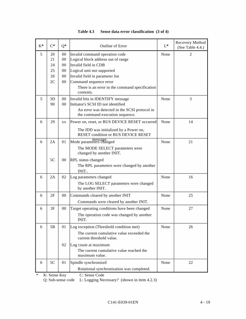
C141-E039-01EN 4 - 19
Table 4.3 Sense data error classification (3 of 4)
K* C* Q* Outline of Error L*Recovery Method(See Table 4.4.)
5 20 00 Invalid command operation code None 221 00 Logical block address out of range24 00 Invalid field in CDB25 00 Logical unit not supported26 00 Invalid field in parameter list2C 00 Command sequence error
There is an error in the command specificationcontents.
5 3D 00 Invalid bits in IDENTIFY message None 390 00 Initiator's SCSI ID not identified
An error was detected in the SCSI protocol inthe command execution sequence.
6 29 xx Power on, reset, or BUS DEVICE RESET occurred None 14
The IDD was initialized by a Power on,RESET condition or BUS DEVICE RESET
message.6 2A 01 Mode parameters changed None 21
The MODE SELECT parameters werechanged by another INIT.
5C 00 RPL status changedThe RPL parameters were changed by anotherINIT..
6 2A 02 Log parameters changed None 16
The LOG SELECT parameters were changedby another INIT.
6 2F 00 Commands cleared by another INIT None 25
Commands were cleared by another INIT.
6 3F 00 Target operating conditions have been changed None 27
The operation code was changed by anotherINIT.
6 5B 01 Log exception (Threshold condition met) None 26
The current cumulative value exceeded thecurrent threshold value.
02 Log count at maximumThe current cumulative value reached themaximum value.
6 5C 01 Spindle synchronized None 22
Rotational synchronization was completed.* K: Sense Key C: Sense Code
Q: Sub-sense code L: Logging Necessary? (shown in item 4.2.3)
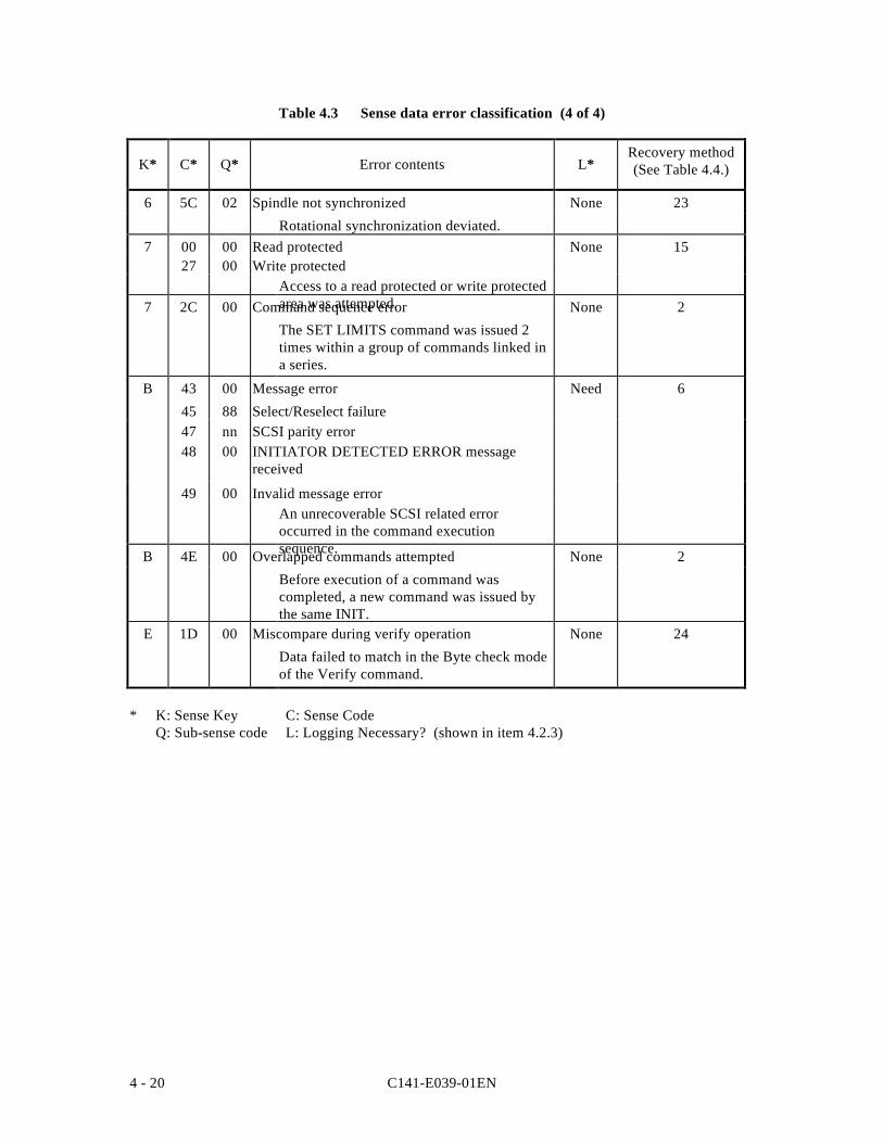
C141-E039-01EN4 - 20
Table 4.3 Sense data error classification (4 of 4)
K* C* Q* Error contents L*Recovery method(See Table 4.4.)
6 5C 02 Spindle not synchronized None 23
Rotational synchronization deviated.7 00 00 Read protected None 15
27 00 Write protectedAccess to a read protected or write protectedarea was attempted.7 2C 00 Command sequence error None 2
The SET LIMITS command was issued 2times within a group of commands linked ina series.
B 43 00 Message error Need 6
45 88 Select/Reselect failure47 nn SCSI parity error48 00 INITIATOR DETECTED ERROR message
received
49 00 Invalid message errorAn unrecoverable SCSI related erroroccurred in the command executionsequence.B 4E 00 Overlapped commands attempted None 2
Before execution of a command wascompleted, a new command was issued bythe same INIT.
E 1D 00 Miscompare during verify operation None 24
Data failed to match in the Byte check modeof the Verify command.
* K: Sense Key C: Sense CodeQ: Sub-sense code L: Logging Necessary? (shown in item 4.2.3)
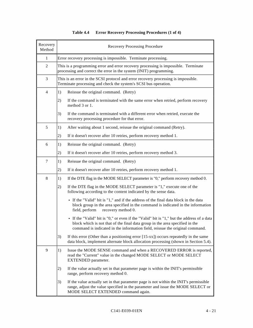
C141-E039-01EN 4 - 21
Table 4.4 Error Recovery Processing Procedures (1 of 4)
RecoveryMethod
Recovery Processing Procedure
1 Error recovery processing is impossible. Terminate processing.
2 This is a programming error and error recovery processing is impossible. Terminateprocessing and correct the error in the system (INIT) programming.
3 This is an error in the SCSI protocol and error recovery processing is impossible.Terminate processing and check the system's SCSI bus operation.
4 1) Reissue the original command. (Retry)
2) If the command is terminated with the same error when retried, perform recoverymethod 3 or 1.
3) If the command is terminated with a different error when retried, execute therecovery processing procedure for that error.
5 1) After waiting about 1 second, reissue the original command (Retry).
2) If it doesn't recover after 10 retries, perform recovery method 1.
6 1) Reissue the original command. (Retry)
2) If it doesn't recover after 10 retries, perform recovery method 3.
7 1) Reissue the original command. (Retry)
2) If it doesn't recover after 10 retries, perform recovery method 1.
8 1) If the DTE flag in the MODE SELECT parameter is "0," perform recovery method 0.
2) If the DTE flag in the MODE SELECT parameter is "1," execute one of thefollowing according to the content indicated by the sense data.
• If the "Valid" bit is "1," and if the address of the final data block in the datablock group in the area specified in the command is indicated in the informationfield, perform recovery method 0.
• If the "Valid" bit is "0," or even if the "Valid" bit is "1," but the address of a datablock which is not that of the final data group in the area specified in thecommand is indicated in the information field, reissue the original command.
3) If this error (Other than a positioning error [15-xx]) occurs repeatedly in the samedata block, implement alternate block allocation processing (shown in Section 5.4).
9 1) Issue the MODE SENSE command and when a RECOVERED ERROR is reported,read the "Current" value in the changed MODE SELECT or MODE SELECTEXTENDED parameter.
2) If the value actually set in that parameter page is within the INIT's permissiblerange, perform recovery method 0.
3) If the value actually set in that parameter page is not within the INIT's permissiblerange, adjust the value specified in the parameter and issue the MODE SELECT orMODE SELECT EXTENDED command again.
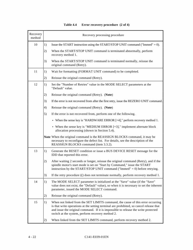
C141-E039-01EN4 - 22
Table 4.4 Error recovery procedure (2 of 4)
Recoverymethod
Recovery processing procedure
10 1) Issue the START instruction using the START/STOP UNIT command ("Immed" = 0).
2) When the START/STOP UNIT command is terminated abnormally, performrecovery method 1.
3) When the START/STOP UNIT command is terminated normally, reissue theoriginal command (Retry).
11 1) Wait for formatting (FORMAT UNIT command) to be completed.
2) Reissue the original command (Retry).
12 1) Set the "Number of Retries" value in the MODE SELECT parameters at the"Default" value.
2) Reissue the original command (Retry). (Note)
3) If the error is not recovered from after the first retry, issue the REZERO UNIT command.
4) Reissue the original command (Retry). (Note)
5) If the error is not recovered from, perform one of the following.
• When the sense key is "HARDWARE ERROR [=4]," perform recovery method 1.
• When the sense key is "MEDIUM ERROR [=3]," implement alternate blockallocation processing (shown in Section 5.4).
Note When the original command is the REASSIGN BLOCKS command, it may benecessary to reconfigure the defect list. For details, see the description of theREASSIGN BLOCKS command (item 3.3.2).
13 1) Generate the RESET condition or issue a BUS DEVICE RESET message for theIDD that reported this error.
2) After waiting 2 seconds or longer, reissue the original command (Retry), and if thespindle motor's start mode is set on "Start by Command," issue the STARTinstruction by the START/STOP UNIT command ("Immed" = 0) before retrying.
3) If the retry procedure (() does not terminate normally, perform recovery method 1.
14 1) The MODE SELECT parameter is initialized at the "Save" value (if the "Save"value does not exist, the "Default" value), so when it is necessary to set the inherentparameter, issued the MODE SELECT command.
2) Reissue the original command (Retry).
15 1) When not linked from the SET LIMITS command, the cause of this error occurringis that write operations at the setting terminal are prohibited, so cancel release thatand issue the original command. If it is impossible to release the write protectedswitch at the system, perform recovery method 2.
2) When linked from the SET LIMITS command, perform recovery method 2.
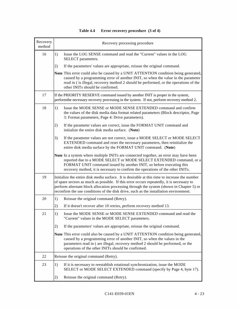
C141-E039-01EN 4 - 23
Table 4.4 Error recovery procedure (3 of 4)
Recoverymethod
Recovery processing procedure
16 1) Issue the LOG SENSE command and read the "Current" values in the LOGSELECT parameters.
2) If the parameters' values are appropriate, reissue the original command.
Note This error could also be caused by a UNIT ATTENTION condition being generated,caused by a programming error of another INIT, so when the value in the parameterread in ( is illegal, recovery method 2 should be performed, or the operations of theother INITs should be confirmed.
17 If the PRIORITY RESERVE command issued by another INIT is proper in the system,performthe necessary recovery processing in the system. If not, perform recovery method 2.
18 1) Issue the MODE SENSE or MODE SENSE EXTENDED command and confirmthe values of the disk media data format related parameters (Block descriptor, Page3: Format parameters, Page 4: Drive parameters).
2) If the parameter values are correct, issue the FORMAT UNIT command andinitialize the entire disk media surface. (Note)
3) If the parameter values are not correct, issue a MODE SELECT or MODE SELECTEXTENDED command and reset the necessary parameters, then reinitialize theentire disk media surface by the FORMAT UNIT command. (Note)
Note In a system where multiple INITs are connected together, an error may have beenreported due to a MODE SELECT or MODE SELECT EXTENDED command, or aFORMAT UNIT command issued by another INIT, so before executing thisrecovery method, it is necessary to confirm the operations of the other INITs.
19 Initialize the entire disk media surface. It is desirable at this time to increase the numberof spare sectors as much as possible. If this error occurs repeatedly, it is necessary toperform alternate block allocation processing through the system (shown in Chapter 5) orreconfirm the use conditions of the disk drive, such as the installation environment.
20 1) Reissue the original command (Retry).
2) If it doesn't recover after 10 retries, perform recovery method 13.
21 1) Issue the MODE SENSE or MODE SENSE EXTENDED command and read the"Current" values in the MODE SELECT parameters.
2) If the parameters' values are appropriate, reissue the original command.
Note This error could also be caused by a UNIT ATTENTION condition being generated,caused by a programming error of another INIT, so when the values in theparameters read in ( are illegal, recovery method 2 should be performed, or theoperations of the other INITs should be confirmed.
22 Reissue the original command (Retry).
23 1) If it is necessary to reestablish rotational synchronization, issue the MODESELECT or MODE SELECT EXTENDED command (specify by Page 4, byte 17).
2) Reissue the original command (Retry).
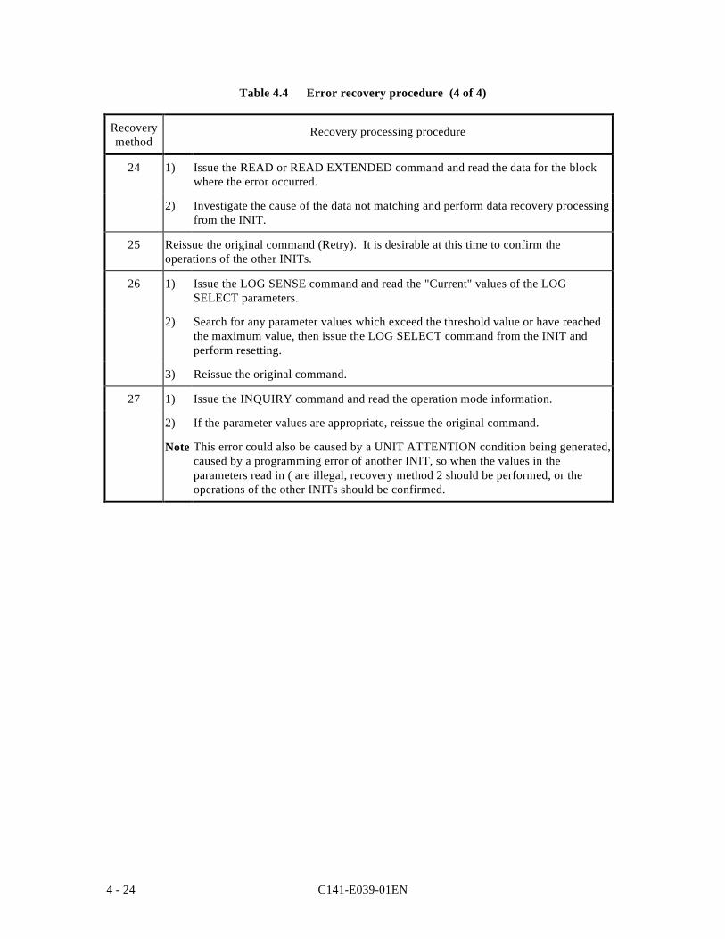
C141-E039-01EN4 - 24
Table 4.4 Error recovery procedure (4 of 4)
Recoverymethod
Recovery processing procedure
24 1) Issue the READ or READ EXTENDED command and read the data for the blockwhere the error occurred.
2) Investigate the cause of the data not matching and perform data recovery processingfrom the INIT.
25 Reissue the original command (Retry). It is desirable at this time to confirm theoperations of the other INITs.
26 1) Issue the LOG SENSE command and read the "Current" values of the LOGSELECT parameters.
2) Search for any parameter values which exceed the threshold value or have reachedthe maximum value, then issue the LOG SELECT command from the INIT andperform resetting.
3) Reissue the original command.
27 1) Issue the INQUIRY command and read the operation mode information.
2) If the parameter values are appropriate, reissue the original command.
Note This error could also be caused by a UNIT ATTENTION condition being generated,caused by a programming error of another INIT, so when the values in theparameters read in ( are illegal, recovery method 2 should be performed, or theoperations of the other INITs should be confirmed.
C141-E039-01EN 4 - 25
4.2.3 Error Logging
In order to collect information that is effective in maintenance, it is desirable for the INIT toaccumulate (log) error information related to the SCSI bus which it has detected itself (BUSFREE errors, command completion wait time-out, etc.) and error information reported by theIDD.
By specifying "1" in the PER bit in the "Read/Write Error Recovery parameter (Page 1) andthe "Verify Error Recovery parameter (Page 7) of the MODE SELECT or MODE SELECTEXTENDED command, the INIT can know of the occurrence of errors which were recoveredfrom successfully by the IDD's internal error recovery processing and their contents. Bylogging that error information, the INIT can obtain data for more detailed analysis of the diskdrive's operating condition.
Concerning the contents of the error log, it is recommended that the data have a time stampaffixed so that they can be edited in a time series of the times the errors were detected, and thatthey include the following information.
• The source which issued the command and the SCSI ID of the SCSI device which was thetarget of the command.
• The CDB which was issued.
• The receiving status, or, when the status was that the command could not be received, thecode showing the type of error detected by the INIT and its content.
• All bytes reported by the IDD.
C141-E039-01EN4 - 26
4.3 Disk Drive Error Recovery Processing
This section explains concerning error recovery processing methods and procedures executedby the IDD for each type of disk drive related error. The INIT can control the error recoveryprocessing methods executed by the IDD using the MODE SELECT parameters.
4.3.1 Error States and Retry Processing Procedures
(1) Seek Error
Mechanical malfunctions of the disk drive during a seek operation and failure of serialaddresses detected during verification of the ID area to match are included in this error.
When a seek error occurs, the IDD first executes rezero seek, then tries repositioning at thetarget cylinder and restarts the original processing. If the error is not recovered from, retryprocessing (rezero seek and repositioning) is performed up to the number of times specified in"Number of Retries during Seek Error" in the MODE SELECT parameters.
If the error cannot be recovered from even when retry processing is executed the specifiednumber of times, the IDD terminates the command which is currently being executed with aCHECK CONDITION status. The sense key in the sense data at this time is "HARDWAREERROR [=4]" and the sense code indicates "Mechanical positioning error [=15-01]' or"Positioning error detected by read of medium [=15-02]."
(2) Read Error in Uncorrectable Data
This error is a failure to detect the Sync Byte pattern during reading of data or an ECC errorfor which correction processing is impossible. If this error is detected, the IDD, after waitingone revolution of the disk media, tries reading again. When the error is not recovered from,reading is retried repeatedly the number of times specified in the MODE SELECT parameter("Number of Retries during Read" or "Number of Retries during Write").
In cases where correction is possible during execution of retry processing, the processingprocedure is according to "Correctable Data Read Error" in item (3). If errors cannot berecovered from even after retry is executed the specified number of times, the IDD terminatesthe command that is currently being executed with a CHECK CONDITION status. The sensekey in the sense data at this time is "MEDIUM ERROR [=3]" and the sense code indicates"Sync byte not found for data field [=13-00]" or "Unrecovered read error [=11-00]."
In this error retry processing, rereading accompanied by head offset processing is performed.
C141-E039-01EN 4 - 27
(3) Correctable Data Read Error
This error is a correctable ECC error when data are being read. Processing methods when thiserror is detected differ depending on the values specified in the EER flag and DCR flag in theMODE SELECT parameters.
If immediate correction of errors is permitted (DCR = 0, EER = 1), the IDD immediatelymakes error corrections in the data buffer and sends the corrected data to the INIT. Also, inthe case of Verify processing, at the point when it judges that correction is possible, it regardsverification as being successful and continues processing of subsequent data blocks.
If error correction is permitted but immediate correction is not permitted (DCR = 0, EER = 0),reading of data as in item (2) is retried up to the number of times specified in the other MODESELECT parameters ("Number of Retries during Read" or "Number of Retries during Write").
If error correction is prohibited (DCR = 1, EER = 0), reading of data as in item (2) is retried upto the number of times specified in "Number of Retries during Read" or "Number of Retriesduring Write."
If the error cannot be recovered from even when this retry processing is executed, the IDDterminates the command that is currently being executed with a CHECK CONDITION status.The sense key in the sense data at this time is "MEDIUM ERROR [=3]" and the sense codeindicates "Unrecovered read error [=11-00]."
(4) Other Internal IDD Errors
If an irrecoverable error other than those in items (1) ~ (3) above is detected internally in theIDD, the IDD terminates the command that is currently being executed with a CHECKCONDITION status. The sense key in the sense data at this time is "HARDWARE ERROR[=4]."
C141-E039-01EN4 - 28
4.3.2 Auto Alternate Block Allocation Processing
The IDD is equipped with a function which automatically executes alternate block allocationprocessing for defective data blocks detected during execution of the WRITE, WRITEEXTENDED, WRITE AND VERIFY, READ and READ EXTENDED commands.
(1) Auto Alternate Block Allocation Processing during a Write Operation
This function is enabled by specifying "1" in the AWRE flag of the MODE SELECTparameters. Furthermore, this function is applicable to the following commands only.
• WRITE Command• WRITE EXTENDED Command• WRITE AND VERIFY Command (Write operation)
When this function is permitted, if, during write processing to the data area, an error which is anobject of retry processing is detected, and which it is impossible to recover from even when readingis retried (see item 4.3.1 (2)) the number of times specified in the "Number of Retries during Write"field in the MODE SELECT parameters, the IDD allocates an alternate block for that data block andexecutes write processing to the data area of the alternate block. Alternate block allocationprocessing is the same as processing with the REASSIGN BLOCKS command.
This function is applied once only during execution of one command. Alternate blockallocation processing and write processing are executed for the first defective data block to bedetected during execution of a command, but if a second defective data block is detected, thecommand that is being executed at that point is terminated with an error. However, by theINIT's reissuing the same command, auto alternate block allocation is applied sequentially anderror recovery can be attempted.
(2) Auto Alternate Block Allocation Processing During a Read Operation
This function is enabled by specifying "1" in the ARRE flag in the MODE SELECTparameters. Furthermore, this function is applicable to the following commands only.
• READ Command• READ EXTENDED Command
When this function is permitted, if, during read processing to the data area, an error which isan object of retry processing is detected, and which it is impossible to recover from even whenreading is retried (see item 4.3.1 (2)) the number of times specified in the "Number of Retriesduring Read" field in the MODE SELECT parameters, the IDD allocates an alternate block forthat data block and executes copying of the alternate block to the data area. Alternate blockallocation processing is the same as processing with the REASSIGN BLOCKS command.Furthermore, recovered data copied to the alternate block are data which are read out, skippingthe ID area, if there is an ID area, or they are data which have been corrected through the ECC.
This function is applied once only during execution of one command. Alternate blockallocation processing and copying are executed for the first defective data block to be detectedduring execution of a command, but if a second defective data block is detected, the commandthat is being executed at that point is terminated with an error. However, by the INIT'sreissuing the same command, auto alternate block allocation is applied sequentially and errorrecovery can be attempted.
C141-E039-01EN 4 - 29
Remark:
1. When this function is specified (ARRE = "1"), the EER flag's specification in theMODE SELECT parameter is made invalid and Read retry processing is performedup to the number of times specified in the "Number of Retries during Read"parameter. If "0" is specified in the DCR flag, correction processing of the data isperformed afterward (see item 4.3.1 (4)). When "1" is specified in the DCR flag,ECC correction processing is prohibited, so even if "1" is specified in the ARRE flag,auto alternate block allocation processing will not be executed for errors in the dataarea.
2. When errors in the data area are recovered from by ECC correction processing, beforeimplementing alternate block allocation processing, rewriting of the recovered dataand a verify check (rereading) are performed. If data are recovered by rewriting,alternate block allocation of that data block is not performed.
3. Auto alternate block allocation processing is executed even if a write operation isprohibited by the SET LIMITS command. However, when a write operation isprohibited through the setting terminal, the auto alternate block allocation processingspecification is disabled.
C141-E039-01EN4 - 30
4.3.3 Error Recovery Processing Control
The INIT can, by specifying the MODE SELECT parameters, can control the error recoveryprocessing (retries) of the IDD with respect to each type of error related to the disk drive.
Table 4.5 shows the types of error and the method of specifying the number of retries forthose errors. for those items where the INIT can specify the number of retries, normally, it isrecommended that the default value or a greater number of times be specified. If a valuesmaller than the default value is specified, and commands are terminated abnormally withouterror recovery processing succeeding, the INIT should reset the corresponding MODESELECT parameters at the default value, then reexecute the original commands.
The MODE SELECT parameters related to disk drive error recovery processing which theINIT can specify are shown below. See the description of the MODE SELECT Command(item 3.1.5) concerning details of the functions of each parameter. The INIT can issue theMODE SELECT or MODE SELECT EXTENDED command as necessary and select the errorrecovery flags and the number of retries.
a. Read/Write Error Recovery Parameters (Page Code = 1)
• AWRE (automatic write reallocation enabled)
• ARRE (automatic read reallocation enabled)
• TB (transfer block)
• EER (enable early recovery)
• PER (post error)
• DTE (disable transfer on error)
• DCR (disable correction)
• Number of retries during read (See Table 4.5)
• Number of retries during write (See Table 4.5)
b Verify Error Recovery Parameters (Page Code = 7)
• EER (enable early recovery)
• PER (post error)
• DTE (disable transfer on error)
• DCR (disable correction)
• Number of retries during verify (See Table 4.5)
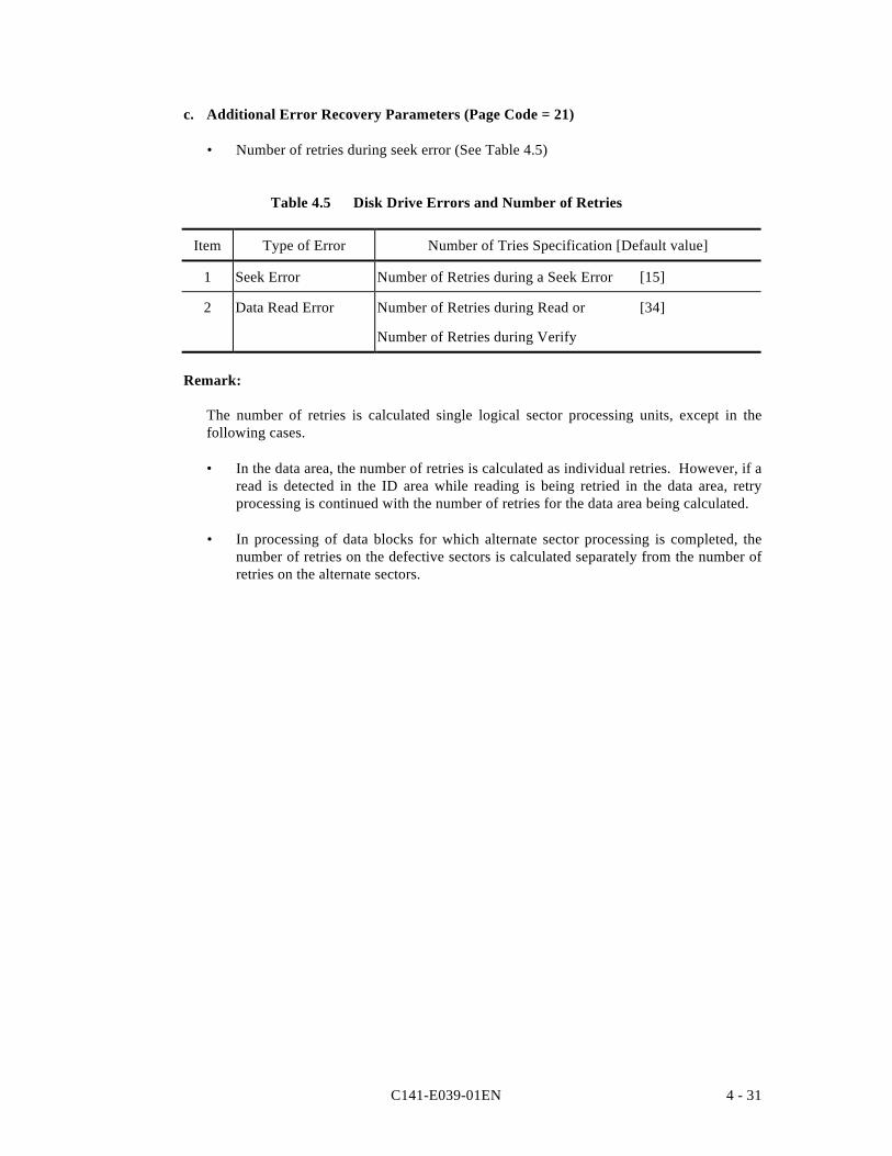
C141-E039-01EN 4 - 31
c. Additional Error Recovery Parameters (Page Code = 21)
• Number of retries during seek error (See Table 4.5)
Table 4.5 Disk Drive Errors and Number of Retries
Item Type of Error Number of Tries Specification [Default value]
1 Seek Error Number of Retries during a Seek Error [15]
2 Data Read Error Number of Retries during Read or [34]
Number of Retries during Verify
Remark:
The number of retries is calculated single logical sector processing units, except in thefollowing cases.
• In the data area, the number of retries is calculated as individual retries. However, if aread is detected in the ID area while reading is being retried in the data area, retryprocessing is continued with the number of retries for the data area being calculated.
• In processing of data blocks for which alternate sector processing is completed, thenumber of retries on the defective sectors is calculated separately from the number ofretries on the alternate sectors.

C141-E039-01EN 5 - 1
CHAPTER 5 DISK MEDIA MANAGEMENT
5.1 Defect Management
5.2 Disk Media Initialization
5.3 Data Block Verification Methods (Recommended)
5.4 Alternate Block Allocation Processing
In this chapter, disk media defect management methods, treatment methods for media defects whichoccur during operation, reinitialization procedures and other disk media management methods arediscussed. Furthermore, see Chapter 3, "Data Format" in the "Product Manual" concerning details ofthe data recording format on the disk media.
5.1 Defect Management
(1) Defect Lists
Information on the positions of defects in the disk media are managed by the types of defectlist shown below. See the description of the FORMAT UNIT command (item 3.3.1)concerning methods for using the defect lists.
• P List Defect position information at the point when the disk drive was shipped from thefactory is recorded in this list. The defective portions included in this list arepermanent defects, and when the disk media is initialized, it is necessary that thislist be used and alternate block processing be executed.
• D List This list includes defect position information specified by the INIT in theFORMAT UNIT command when initializing the disk media.
• C List This list contains information on the positions of defective blocks detected duringthe data block Verify operation (Certification) after initialization by the FORMATUNIT command. This information is generated internally by the IDD when theFORMAT UNIT command is executed.
• G List This list is composed from the defective logical data block position informationspecified by the INIT in the REASSIGN BLOCKS command, defective logicaldata block position information from alternate blocks which have been allocatedby the IDD's auto alternate block allocation processing, information specified asthe D List and information generated as the C List.
The P List and G List are recorded in the system space on the disk media. The INIT can readthe contents of these lists by the READ DEFECT DATA command.
5 - 2 C141-E039-01EN
(2) Alternate Block Allocation
Alternate data blocks are allocated in defective sector units for defective data blocks (=sectors) on the disk media by the IDD's internal defect management methods.
a. Spare Sector Area
Spare sectors for allocation as alternate blocks are secured in one or both of the followingareas. When the INIT initializes the disk media, it can specify the spare sector area to beprepared on the disk drive and the size of that area. For details, see the description in 3.1.2"Spare Area for Alternates" in the "Product Manual."
• Spare Sectors Within a CylinderSpare sectors are secured in the final track of each cylinder. They are used as alternateblocks for defective sectors within the same cylinder.
• Alternate CylindersThis is an exclusive cylinder for allocation of alternate blocks. Alternate cylinders aresecured only in the specified quantity in order from the topmost cylinder. Spare sectors inan alternate cylinder are used only in the case that the spare sectors within each cylinderare used up and alternate block allocation is not possible within the same cylinder.
b. Alternate Block Allocation Methods
Alternate block allocation processing is performed using one of the following methods.
• Sector Slip ProcessingThis is a method of skipping defective sectors and writing the logical data blockscorresponding to those sectors in order in physically consecutive sectors. Sector slipprocessing is performed only within the same cylinder as the defective sectors and until allthe spare sectors within that cylinder are used up.
• Alternate Sector ProcessingThis is a method of allocating logical data blocks corresponding to defective sectors tounused spare sectors within the same cylinder or to unused spare sectors in an alternatecylinder.
c. Alternate Block Allocation Processing
Alternate block allocation processing is implemented by the FORMAT UNIT command,REASSIGN BLOCKS command or "Auto Alternate Block Allocation Processing." Insector slip processing, the defective sectors re excluded and logical data blocks are locatedin physically consecutive sectors, but when alternate block processing is performed, theaffected logical data blocks are located in spare sectors which are not physicallyconsecutive with the previous and following logical data blocks which are physicallylocated on the disk. For details, see the description in 3.3.2 "Alternate Block Allocation"in the "Product Manual."
C141-E039-01EN 5 - 3
• Alternate Block Allocation Processing During FORMAT UNIT CommandExecution
With the FORMAT UNIT command, alternate block allocation is done by sector slipprocessing until all the spare sectors within the same cylinder have been used up fordefective sectors included in the type of defect list (P, G or D) specified in thecommand. When all the spare sectors in the same cylinder have been used up,subsequent defective sectors in that cylinder are treated by allocating spare sectors inan alternate cylinder by alternate sector processing.
After implementing this alternate block allocation and initializing the disk media, attimes when a data block Verify (Certification) operation is not prohibited, the IDD,reads all the initialized data blocks and verifies their normalcy. If a defective datablock is detected during this processing, the IDD generates the C List as defectposition information and allocates alternate blocks by alternate sector processing forthose defective data blocks. In this case, if there are any unused spare sectors in thesame cylinder as the defective data blocks, alternate blocks are allocated within thesame cylinder, but if the spare sectors are all used up in the same cylinder, alternateblocks are allocated in spare sectors in an alternate cylinder.
• Alternate Block Allocation Processing by the REASSIGN BLOCKS Command
With the REASSIGN BLOCKS command, alternate block allocation is performed byalternate sector processing for defective logical data blocks specified by the INIT. Inthis case, if there are unused spare sectors in the same cylinder as the specifieddefective logical data blocks, alternate block allocation is done within the samecylinder, but if all the spare sectors in the same cylinder have been used up, alternateblocks are allocated in spare sectors in an alternate cylinder.
• Auto Alternate Block Allocation Processing
If auto alternate block allocation processing is permitted by the AWRE flag or theARRE flag of the MODE SELECT parameters, the IDD executes alternate clockallocation automatically by alternate sector processing for defective data blocksdetected during execution of the WRITE, WRITE EXTENDED, WRITE ANDVERIFY, READ and READ EXTENDED commands. The alternate block allocationmethod in this case is the same as in the case of the REASSIGN BLOCKS command.See the description in item 4.3.2 concerning "Auto Alternate Block AllocationProcessing.
5 - 4 C141-E039-01EN
5.2 Disk Media Initialization
5.2.1 Initialization During Installation
The disk drive is initialized for the inherent (default) data format for each respective modelname (model class) when it is shipped from the factory, so ordinarily, it is not necessary toinitialized (format) the disk media when it is installed in a system. However, in cases wheredata attributes which differ from the default format are necessary, initialization (formatting) ofthe entire disk media by the following procedures is necessary. At this time, the INIT canchange the following data format attributes.
• The logical data block length.• The number of logical data blocks or the number of cylinders in the User Space.• The size of the spare area for alternate blocks.
(1) Issuing the MODE SELECT Command
The MODE SELECT or MODE SELECT EXTENDED command is issued and the formatattributes on the disk media are specified. The necessary parameters at this time are asfollows.
a. Block Descriptor
The logical data block size (byte length) is specified in the "Data block length" field.Also, when desiring to clearly specify the logical data block count, specify that value inthe "Data block count" field. If not, zero may be specified in the "Data block count" field.In that case, the number of logical data blocks after initialization will be determined by thevalues specified in the Format parameters (Page 3) and the Drive parameters (Page 4).
b. Format Parameters (Page 3)
Specify the number of spare sectors secured in each cylinder in the "Alternate sectorcount/zone" field. It is desirable not to specify a value that is lower than the IDD's defaultvalue in this field.
c. Drive Parameters (Page 4)
When desiring to clearly specify the number of cylinders in the "User Space," specify thatvalue in the "Cylinder count" field. In this case, it is necessary to note that the number ofcylinders in the User Space includes the number of alternate cylinders specified in theFormat parameters (Page 3). When it is not particularly necessary to specify the number ofcylinders, zero, or a value equal to the default value, may be specified in the "Cylindercount" field. In this case, the number of cylinders necessary to secure the number oflogical data blocks specified in the "Data block count" field in the block descriptor, or themaximum number of cylinders that can be used as User Space on the disk drive,whichever is smaller, will be allocated to user space. Furthermore, if zero is specified inboth the "Cylinder count" field and the "Data block count" field in the block descriptor,the maximum number of cylinders on the disk drive that can be used as User Space will beallocated to User Space.
C141-E039-01EN 5 - 5
(2) Issuing the FORMAT UNIT Command
Issue the FORMAT UNIT command and initialize the entire disk media surface.
In this FORMAT UNIT command, the entire disk media surface is initialized using the P List,then after initialization, the data blocks are verified. If any defective blocks are detected in theVerify operation, alternate blocks are allocated for those data blocks. Also, the defect positioninformation for only the defective data blocks detected in the Verify operation is recorded inthe G List.
The contents which need to be specified at this time are as follows.
a. CDB Specification
Specify "0" in the "FmtData" bit and the "CmpLst" and "000" in the "Defect List Format"field in the CDB.
b. FORMAT Parameters
If the items values in the previous item are specified in the CDB, the Format parameter isnot necessary.
5 - 6 C141-E039-01EN
5.2.2 Re-initialization
The INIT can reinitialize the disk drive after it has been operated using the FORMAT UNITcommand.
Note:If it is necessary after reinitialization to restore the data that were stored on the disk media,it is necessary to save the data before executing reinitialization, then execute data restoreusing system software after reinitialization.
The INIT can change the size of the spare sector area and its location as well as the number oflogical data blocks before reinitialization. The recommended procedure for reinitialization isshown below. However, in cases where the logical data block length is changed, theinitialization procedure described in item 5.2.1 must be followed during installation.
(1) MODE SELECT Command
If the logical data block count (size of the User Space) or the size of the spare sector area andits location are changed, issue the MODE SELECT EXTENDED command and specify thedisk media format attributes. The parameter specification method is the same as in the case ofinitialization processing during installation, described in item 5.2.1. If the same formatattributes as at present will continue to be used, it is not necessary to issue the MODESELECT EXTENDED command.
(2) FORMAT UNIT Command
Issue the FORMAT UNIT command in either of the following two formats and initialize theentire disk media surface.
a) Specify "1" in the "FmtData" bit, "0" in the "CmpLst" bit and "000" in the "Defect ListFormat" field. Also, prepare only a 4-byte header, specify "0" in the "FOV," "DPRY,""DCRT" and "STPF" bits and zero in the "Defect List Length" field.
• In this FORMAT UNIT command, the entire disk media surface is initialized usingthe P List and the previously existing G List, then after initialization, the data blocksare verified. If any defective blocks are detected in the Verify operation, alternateblocks are allocated for those data blocks. Also, the previously existing G List issaved, and the defect position information for the defective data blocks detected in theVerify operation is added to the G List. During initialization, alternate blocks forwhich sector slip processing was applied for previously known defects are reallocated,so optimization of the logical data block locations on the disk media can be expected.
b) Specify "0" in the "FmtData" bit and in the "CmpLst" bit and "000" in the "Defect ListFormat" field. In this case, specification of the format parameters is not necessary.
• In this FORMAT UNIT command, the disk media is initialized using only the P List,then after initialization, the data blocks are verified. If any defective blocks aredetected in the Verify operation, alternate blocks are allocated for those data blocks.Also, the previously existing G List is erased and defect position information for thedefective data blocks detected in the Verify operation is recorded in a new G List.
C141-E039-01EN 5 - 7
5.3 Data Block Verification Methods (Recommended)
The recommended procedure for verifying from the INIT the normalcy of logical data blockslocated on the disk media is as shown below. It is desirable for the INIT to verify the datablocks after initialization of the disk media is completed or when executing alternate blockallocation processing by the REASSIGN BLOCKS command.
Note:
The INIT must not recognize the defective data blocks included in the P List as normaldata blocks in the verification operation.
After the INIT has written a specific data pattern for logical data blocks which is the object ofverification using the procedure described below, it next reads those data or verifies the datablocks by executing Verify.
(1) Setting Parameters by the MODE SELECT Command
Issue the MODE SELECT or the MODE SELECT EXTENDED command and prohibit retryprocessing, data correction and operation of the Read-Ahead Cache feature. The necessaryparameter settings are as shown below.
a. Read/Write Error Recovery Parameters (Page 1)
• AWRE = 0, ARRE = 0
• TB = 0 or 1
• EER = 0, PER = 1, DTE = 1, and DCR = 1
• Number of Retries during Read = Zero
• Number of Retries during Write = Zero
b. Verify Error Recovery Parameters (Page 1)
• EER = 0, PER = 1, DTE = 1, and DCR = 1
• Number of Retries during Verify = Zero
c. Caching Parameters (Page 8)
• RCD = 1
5 - 8 C141-E039-01EN
(2) Writing a Data Pattern
Write a data pattern for verification in the data block which is the object. The recommendeddata pattern at this time is X '0123456789ABCDEF' repeated. The WRITE, WRITEEXTENDED or WRITE SAME command can be used to write data.
(3) Reading and Verification of Data
Issue the READ, READ EXTENDED or VERIFY command and verify that the data written tothe disk media in item (2) were read correctly.
To verify reading of data, it is recommended that reading of the same data block be done atlease 2 times, but the number of times verification is performed is determined by theconditions on the system. If reading of all data is completed normally, it can be recognizedthat use of that data block can be used normally.
(4) Error Verification
When an error related to the disk media (Sense Key = 3: MEDIUM ERROR) occurs duringwriting of the data pattern (see item (2)) or verification of data reading (see item (3)), reexecutethe rewriting and reading verification combination (two times) at least 8 times.
When the same type of error occurs even once during reexecution, it is recommended that theINIT treat that data block as a defective block. If the reexecution of verification is completednormally every time, it should be regarded that that data block can be used normally.
C141-E039-01EN 5 - 9
5.4 Alternate Block Allocation Processing
If errors on the disk media which cannot be recovered from are detected, or if a recoverableerror occurs repeatedly in the same data block, it is necessary for the INIT to allocate analternate block for the data block where the error occurred using the REASSIGN BLOCKScommand. The procedure for alternate block processing is shown below.
Note:
An attempt will be made to copy the contents of the data area of the logical data blockspecified in the "Defect Data" list to the alternate block allocated by this command, but insome cases, the data cannot be copied. Confirmation of the contents of data in theallocated alternate block, saving of data before issuing this command and restoring of dataafter executing this command are the responsibility of the INIT.
1) Verify data blocks in accordance with the procedure in Section 5.3 for data blocks whereerror occur. When such a data block is judged to be normal, alternate block allocationneed not be implemented. In this case, rewrite the original data to that data block ifnecessary. When the data block is judged to be defective, implement the processing initem 2) and after.
2) Specify a logical block address for a data block which is judged to be defective and issuethe REASSIGN BLOCKS command.
3) If the REASSIGN BLOCKS command is terminated normally, verify that logical datablock according to the procedure in Section 5.3. If that data block is judged to be correct,allocate an alternate block and terminate processing. When the data block is judged to bedefective, return to 2) and issue the REASSIGN BLOCKS command again, then tryreallocating another alternate block for that logical data block.
The alternate block allocation history (defect position information) is registered as an additionto the defect list (G List). Therefore, when reinitializing the hard disk with the FORMATUNIT command (see item 5.2.2), if use of the G List is specified, defect processing can beperformed which reflects the operation results up to that time. Also, since "Alternate sectorprocessing" is applied in alternate block allocation in the REASSIGN BLOCKS command, thephysical connectivity of the logical data block positions on the disk media is destroyed, but byreinitializing the disk, as long as the number of defective sectors in the cylinder does notexceed the number of spare sectors per cylinder, the logical data blocks are relocated by sectorslip processing so that their physical connectivity is maintained.

C141-E039-01EN GL - 1
Glossary
Bus Condition ..........This is an asynchronous condition for changing the status transition on the SCSIbus. There are two types, the ATTENTION condition and the RESET condition.
Bus Phase.................This is the name given to the SCSI bus state. The SCSI bus is in one state oranother, the BUS FREE phase, the ARBITRATION phase, the SELECT phase,the RESELECTION phase or the INFORMATION TRANSFER phase. Inaddition, the INFORMATION TRANSFER phase is subdivided into the DATAIN, DATA OUT, COMMAND, STATUS, MESSAGE AND MESSAGE OUTphases in accordance with the type of information being transferred in theINFORMATION TRANSFER phase.
CCS ........................Common Command SetThis is the standard form of SCSI logical specifications stipulated by theoperations subcommittee of the American National Standards Institute (ANSI)which stipulates functions which a direct access device (magnetic disk, etc.)should support.
CDB ........................Command Descriptor BlockA series of data which describes commands related to input/output operations,sent from the initiator to the target.
Command.................This is a command to a target to perform an input/output operation, and it isdescribed as the CDB.
Disconnect................This is processing which temporarily frees the connected state of the target withthe SCSI bus and the initiator at the point in the target's command processingexecution process when operations on the SCSI bus are not needed.
Initiator (INIT) ........This is a SCSI device which initiates input and output operations on the SCSIbus. In this manual, initiator has been abbreviated to "INIT."
Logical Unit .............This is the device unit which is the object of input/output operations on the SCSIbus.
LUN ........................Logical Unit NumberThis is the serial number which identifies a logical unit.
Message ...................This is control information that is delivered and received between the initiatorsand targets operating on the SCSI bus for controlling a series of bus phases andinput/output operation execution sequences.
Reconnect.................For a target which has executed disconnect processing, this is processing whichreconnects tot he initiator at the point when operations on the SCSI bus againbecome necessary.
C141-E039-01ENGL - 2
SCSI ........................Small Computer System InterfaceThe standardized input/output interface of the American National StandardsInstitute (ANSI). [Standard No.: ANSI X3. 131-1986]
SCSI Device.............The general name given to a device which is connected to the SCSI bus(input/output device, I/O controller, host adapter, etc.).
SCSI ID....................On the SCSI bus, this is the physical serial number which identifies a SCSIdevice. This is a unique value for each SCSI device and the ID can be assignedfrom #0~#7 to correspond to the bit number of the SCSI data bus.
Sense Code...............This is a 1-byte code displayed in the sense data and is information whichspecifies the type of error that was detected.
Sense Data................When several items of error information are included in a command's completionstatus, this is information generated by the target for reporting detailedinformation on that status.
Sense Key.................This is a 4-bit code displayed in the sense data. It contains information forclassifying the type of error that was detected.
Status........................This is 1 byte of information reported to the initiator by the target device whenexecution of each command is completed, which displays the command'scompletion state.
Target (TARG).........This is the SCSI device that executes the input/output operations initiated by theinitiator (INIT). In this manual, target is abbreviated "TARG."
C141-E039-01EN AB - 1
A
ACK AcknowledgeATN AttentionAWG American Wire Gauge
B
BSY Busy
C
C/D Control/dataCCS Common command setCDB Common descriptor block
D
DB Data busDBP Data Bus ParityDC Direct current
E
EIA Engineering Industries Association
G
GND Ground
I
I/O Input/outputID IdentifierIDD Intelligent disk driveINIT InitiatorISO International Organization for
Standardization
L
LSB Least significant byteLUN Logical unit number
M
MSB Most significant byteMSG Message
O
OEM Original equipment manufacturer
R
REQ RequestRST Reset
S
SCSI Small Computer System InterfaceSDTR Synchronous data transfer requestSEL Select
T
TARG TARGetTRM Terminator
Abbreviation
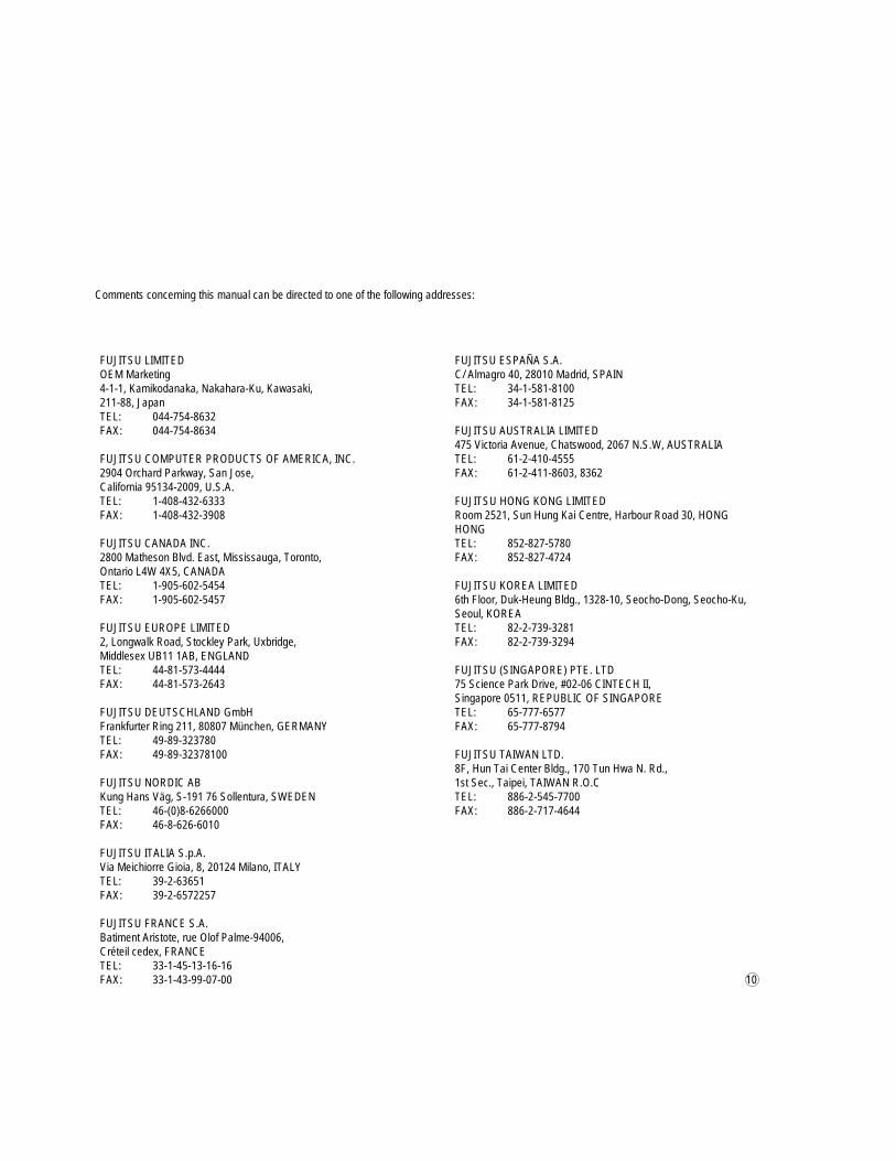
FUJITSU LIMITEDOEM Marketing4-1-1, Kamikodanaka, Nakahara-Ku, Kawasaki,211-88, JapanTEL: 044-754-8632FAX: 044-754-8634
FUJITSU COMPUTER PRODUCTS OF AMERICA, INC.2904 Orchard Parkway, San Jose,California 95134-2009, U.S.A.TEL: 1-408-432-6333FAX: 1-408-432-3908
FUJITSU CANADA INC.2800 Matheson Blvd. East, Mississauga, Toronto,Ontario L4W 4X5, CANADATEL: 1-905-602-5454FAX: 1-905-602-5457
FUJITSU EUROPE LIMITED2, Longwalk Road, Stockley Park, Uxbridge,Middlesex UB11 1AB, ENGLANDTEL: 44-81-573-4444FAX: 44-81-573-2643
FUJITSU DEUTSCHLAND GmbHFrankfurter Ring 211, 80807 München, GERMANYTEL: 49-89-323780FAX: 49-89-32378100
FUJITSU NORDIC ABKung Hans Väg, S-191 76 Sollentura, SWEDENTEL: 46-(0)8-6266000FAX: 46-8-626-6010
FUJITSU ITALIA S.p.A.Via Meichiorre Gioia, 8, 20124 Milano, ITALYTEL: 39-2-63651FAX: 39-2-6572257
FUJITSU FRANCE S.A.Batiment Aristote, rue Olof Palme-94006,Créteil cedex, FRANCETEL: 33-1-45-13-16-16FAX: 33-1-43-99-07-00
FUJITSU ESPAÑA S.A.C/ Almagro 40, 28010 Madrid, SPAINTEL: 34-1-581-8100FAX: 34-1-581-8125
FUJITSU AUSTRALIA LIMITED475 Victoria Avenue, Chatswood, 2067 N.S.W, AUSTRALIATEL: 61-2-410-4555FAX: 61-2-411-8603, 8362
FUJITSU HONG KONG LIMITEDRoom 2521, Sun Hung Kai Centre, Harbour Road 30, HONGHONGTEL: 852-827-5780FAX: 852-827-4724
FUJITSU KOREA LIMITED6th Floor, Duk-Heung Bldg., 1328-10, Seocho-Dong, Seocho-Ku,Seoul, KOREATEL: 82-2-739-3281FAX: 82-2-739-3294
FUJITSU (SINGAPORE) PTE. LTD75 Science Park Drive, #02-06 CINTECH II,Singapore 0511, REPUBLIC OF SINGAPORETEL: 65-777-6577FAX: 65-777-8794
FUJITSU TAIWAN LTD.8F, Hun Tai Center Bldg., 170 Tun Hwa N. Rd.,1st Sec., Taipei, TAIWAN R.O.CTEL: 886-2-545-7700FAX: 886-2-717-4644
10
Comments concerning this manual can be directed to one of the following addresses:
FUJITSU LIMITED
Thank you for your interest. Please send this sheet to one of the addresses in the left page.
Reader Comment FormWe would appreciate your comments and suggestions for improving this publication.
Publication No. Rev. Letter Title Current Date
How did you use this publication? Is the material presented effectively?
What is your overall rating of this publication? What is your occupation?
Your other comments may be entered here. Please be specific and give page,paragraph and line number references where applicable.
Your Name & Return Address
Sales
OperatingInstalling
Maintaining
Learning
Reference
Fair
Poor
Very Good
GoodVery Poor
Fullycovered
WellIllustrated
WellOrganized
Clean