Embed Size (px)
Citation preview
De
sig
ns
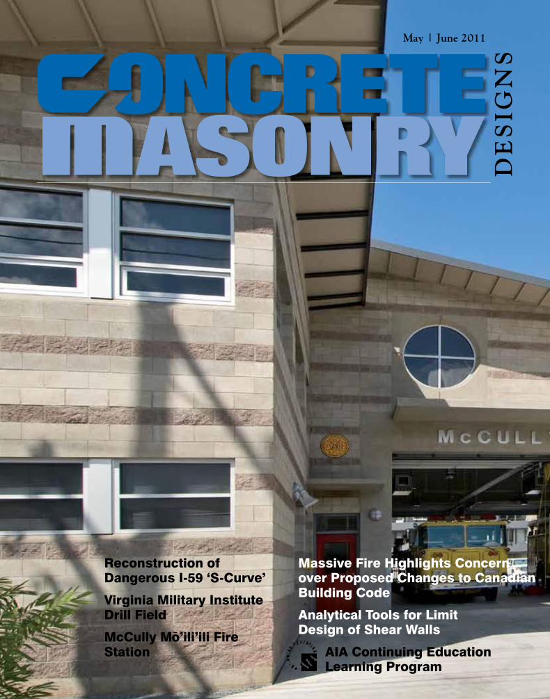
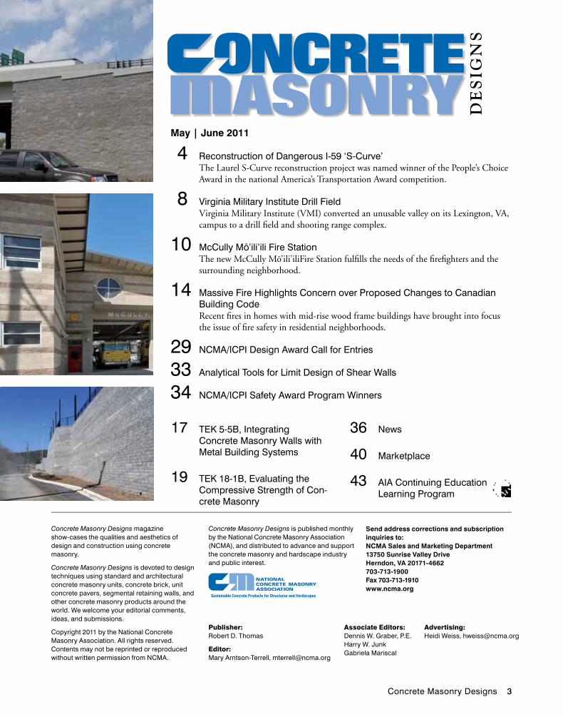
May | June 2011
ASONRY
Reconstruction of Dangerous I-59 ‘S-Curve’
Virginia Military Institute Drill Field
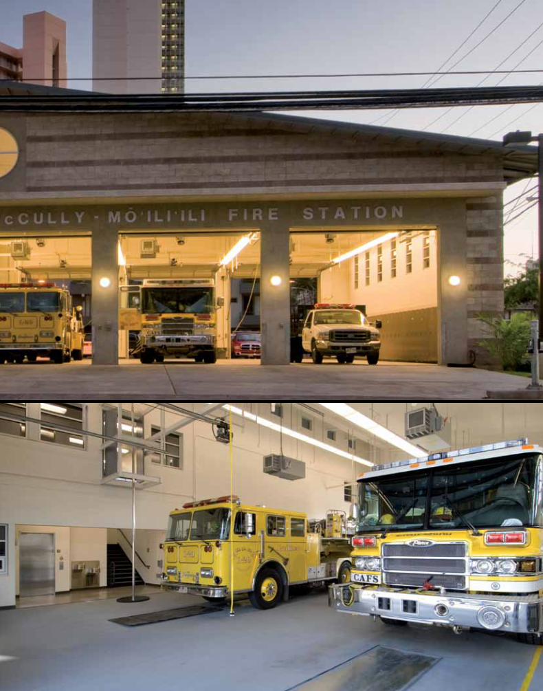
McCully Mo’ili’ili Fire Station
Massive Fire Highlights Concern over Proposed Changes to Canadian Building Code
Analytical Tools for Limit Design of Shear Walls
AIA Continuing Education Learning Program
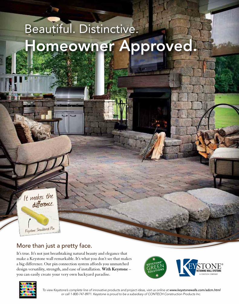
Beautiful. Distinctive.
Homeowner Approved.
More than just a pretty face.It’s true. It’s not just breathtaking natural beauty and elegance that make a Keystone wall remarkable. It’s what you don’t see that makes a big difference. Our pin connection system affords you unmatched design versatility, strength, and ease of installation. With Keystone – you can easily create your very own backyard paradise.
It makes the difference.difference.difference.
Keystone Shouldered Pin
KEYSTONE®
GREEN SOLUTIONS
To view Keystone’s complete line of innovative products and project ideas, visit us online at www.keystonewalls.com/adcm.html or call 1-800-747-8971. Keystone is proud to be a subsidiary of CONTECH Construction Products Inc.
Keystone-H1-8.25x10.75.indd 1 5/17/11 12:15 PM
Concrete Masonry Designs 3
17 TEK 5-5B, Integrating Concrete Masonry Walls with Metal Building Systems
19 TEK 18-1B, Evaluating the Compressive Strength of Con-crete Masonry
36 News
40 Marketplace
43 AIA Continuing Education Learning Program
De
sig
ns
ASONRY4 Reconstruction of Dangerous I-59 ‘S-Curve’
The Laurel S-Curve reconstruction project was named winner of the People’s Choice Award in the national America’s Transportation Award competition.
8 Virginia Military Institute Drill FieldVirginia Military Institute (VMI) converted an unusable valley on its Lexington, VA, campus to a drill field and shooting range complex.
10 McCully Mo’ili’ili Fire StationThe new McCully Mo’ili’iliFire Station fulfills the needs of the firefighters and the surrounding neighborhood.
14 Massive Fire Highlights Concern over Proposed Changes to Canadian Building CodeRecent fires in homes with mid-rise wood frame buildings have brought into focus the issue of fire safety in residential neighborhoods.
29 NCMA/ICPI Design Award Call for Entries
33 Analytical Tools for Limit Design of Shear Walls
34 NCMA/ICPI Safety Award Program Winners
May | June 2011
Concrete Masonry Designs magazine show-cases the qualities and aesthetics of design and construction using concrete masonry.
Concrete Masonry Designs is devoted to design techniques using standard and architectural concrete masonry units, concrete brick, unit concrete pavers, segmental retaining walls, and other concrete masonry products around the world. We welcome your editorial comments, ideas, and submissions.
Copyright 2011 by the National Concrete Masonry Association. All rights reserved. Contents may not be reprinted or reproduced without written permission from NCMA.
Concrete Masonry Designs is published monthly by the National Concrete Masonry Association (NCMA), and distributed to advance and support the concrete masonry and hardscape industry and public interest.
Send address corrections and subscription inquiries to: NCMA Sales and Marketing Department13750 Sunrise Valley DriveHerndon, VA 20171-4662703-713-1900 Fax 703-713-1910www.ncma.org
Publisher: Robert D. Thomas
Editor: Mary Arntson-Terrell, [email protected]
Associate Editors: Dennis W. Graber, P.E. Harry W. Junk Gabriela Mariscal
Advertising: Heidi Weiss, [email protected]
Beautiful. Distinctive.
Homeowner Approved.
More than just a pretty face.It’s true. It’s not just breathtaking natural beauty and elegance that make a Keystone wall remarkable. It’s what you don’t see that makes a big difference. Our pin connection system affords you unmatched design versatility, strength, and ease of installation. With Keystone – you can easily create your very own backyard paradise.
It makes the difference.
Keystone Shouldered Pin
KEYSTONE®
GREEN SOLUTIONS
To view Keystone’s complete line of innovative products and project ideas, visit us online at www.keystonewalls.com/adcm.html or call 1-800-747-8971. Keystone is proud to be a subsidiary of CONTECH Construction Products Inc.
Keystone-H1-8.25x10.75.indd 1 5/17/11 12:15 PM
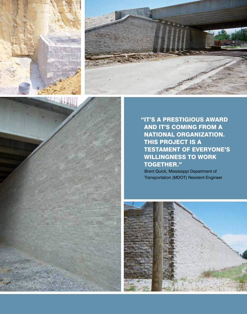
“ IT’S A PRESTIgIouS AWARD AnD IT’S CoMIng FRoM A nATIonAL oRgAnIzATIon. THIS PRojECT IS A TESTAMEnT oF EVERyonE’S WILLIngnESS To WoRk TogETHER.”
Brent Quick, Mississippi Department of
Transportation (MDOT) Resident Engineer
Concrete Masonry Designs 5
The Laurel S-Curve reconstruction project was named winner of the People’s Choice Award in the national America’s Transportation Award competition. The project received more than
270,000 votes by people of Mississippi, who delivered a landslide victory in the contest, sponsored by the Amer-ican Association of State Highway and Transportation Officials (AASHTO). The Laurel S-Curve was named a regional winner of the America’s Transportation Award and competed with other regional winners across the U.S. for the People’s Choice Award.
“The purpose of this competition was to increase awareness and support of transportation, and Missis-sippi has demonstrated a keen appreciation for the role of highways and bridges in our everyday life,” said Larry L. “Butch” Brown, MDOT Executive Director and former President of AASHTO. “Thank you to all who voted, and a special thank you to the men and women who were on the front lines of this project, guiding it through a long development process to successful completion.”
MDOT reconstructed and realigned a 3,700-foot (1,128 m) segment of I-59 through Laurel, Mississippi, eliminating the notorious Laurel S-curve, which had one of the highest crash rates in the state. The reconstructed segment crosses six local streets and the Norfolk Southern Railroad, requiring a 1,980-foot-long (604 m), six-lane bridge, along with a total of 1,350 feet (411 m) of ele-vated ramp structures, two on-ramps, and one off-ramp.
LaureL S-Curve
Project LocationLaurel, MSProject ownerMississippi Department of TransportationProject engineerTanner Construction, Laurel, MSSrw DeSign/BuiLD contractorSynergy Earth Systems, LLC, Daphne, ALSrw ProDucerBlock USA, Montgomery, ALSrw LicenSorTensar International Corporation, Atlanta, GA
The dangerous 3,700-foot (1,128 m) stretch of I-59 was constructed prior to adoption of current Interstate standards and wove through urban obstacles. Motor-ists were confronted with sharp curves, narrow lanes, low clearances, no shoulders, and inadequate merge areas. This prompted city officials to look into improving the “Laurel S-Curve” over 20 years ago.
A location committee, consisting of MDOT and FHWA representatives, met in early 1986 to review the project and develop alternatives. In 1988 the environ-mental assessment was completed. The result of the study was a plan to relocate Interstate 59 through the Laurel Housing Authority units on Beacon Street to straighten out the alignment. The process of moving the 72 housing units was lenghty, and construction on the replacement units was started six years later in 2002. At this point MDOT hired an engineering consulting firm to re-eval-uate the design of the S-curve project using current traf-fic data. From 2004 to 2005, construction plans evolved based on current traffic data, public hearings, and more economical building options. The underground structure work for the bridge supports began in July 2006—20 years after the process began.
Now that the project has been completed, it has dra-matically improved safety, smoothed traffic flow, and was ultimately delivered under budget. In fact, design changes, proactive coordination, and innovative financing produced a budget surplus of $6 million, which is being used to widen five additional I-59 bridges and two addi-tional miles of roadway north of the S-Curve.
How Did they Do It?The new highway design called for a segmental retain-ing wall to be used beneath one of the bridge abutments and along the side of the highway. The Mississippi DOT (MDOT) saw the aesthetic and economic benefits of using a segmental retaining wall system over other wall types. MDOT also selected a section of highway near the segmental block wall that would utilize a wire faced tem-porary wall system.
Steven Parker, project manager, said that that the first priority was to correct the slopes between the avenues to
REConSTRuCTIon PRojECT IS A
WInnER
6 Concrete Masonry Designs
the required specifications and complete the lane widen-ing process. “These modular block walls allow MDOT to obtain the required slopes without acquiring additional right-of-way. Two more walls are scheduled to be installed around the Highway 84 connection in the upcoming months,” added Parker.
The SRW system selected has proven performance in critical live-load applications for highway bridges and abutments. The bridge abutments were installed on drilled shafts as recommended by AASHTO stan-dards. The SRW units were created to have a compressive strength of 4,000 psi (28 MPa) and 6% absorption (state required).
During the design of the segmental block wall, the SRW contractor and the project engineer were able to work together to incorporate a backfill material that was much more cost effective that the standard #57 Stone used on most DOT projects. This allowed for some cost savings and reduced the chance of delays due to a local shortage of #57 Stone.
MDOT had a concern about the possibility of the soil behind the abutment backwall pushing enough to
cause the drilled shafts beneath the abutment to move. The SRW contractor proposed the use of a welded wire form pressure relief wall behind the abutment backwall to reduce the soil pressures on it.This proposal was accepted by MDOT and incorporated into the design.
The final wall drawings called for about 10,000 sf (929 m2) of segmental block wall and about 1,500 sf of wire faced walls.
Cause for CelebrationAfter the project won the regional AASHTO award, offi-cials encouraged people to become excited and take part in the nationally recognized People’s Choice Award selec-tion process. A rally was held on the steps of Laurel City Hall where they told the crowd that they could bring national recognition to the local project.
Among the speakers was State Rep. Omeria Scott, Dis-trict 80. “This project is deserving of recognition,” Scott said, adding that appreciation also goes to the state’s appropriations committee for its assistance. “This project is already a winner. …It’s made a difference in the lives of the people here.”
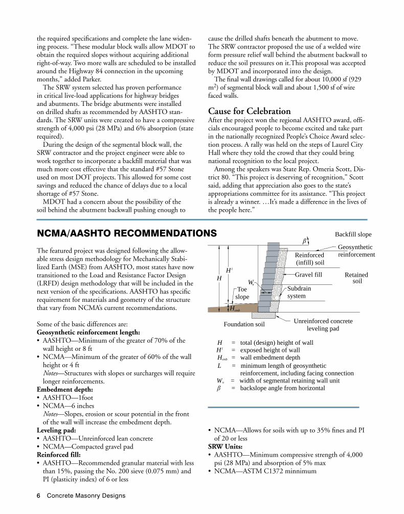
The featured project was designed following the allow-able stress design methodology for Mechanically Stabi-lized Earth (MSE) from AASHTO, most states have now transitioned to the Load and Resistance Factor Design (LRFD) design methodology that will be included in the next version of the specifications. AASHTO has specific requirement for materials and geometry of the structure that vary from NCMA’s current recommendations.
Some of the basic differences are:Geosynthetic reinforcement length: • AASHTO—Minimumofthegreaterof70%ofthe
wall height or 8 ft • NCMA—Minimumofthegreaterof60%ofthewall
height or 4 ft Notes—Structures with slopes or surcharges will require
longer reinforcements.Embedment depth: • AASHTO—1foot• NCMA—6inches Notes—Slopes, erosion or scour potential in the front
of the wall will increase the embedment depth.Leveling pad: • AASHTO—Unreinforcedleanconcrete• NCMA—CompactedgravelpadReinforced fill: • AASHTO—Recommendedgranularmaterialwithless
than 15%, passing the No. 200 sieve (0.075 mm) and PI (plasticity index) of 6 or less
Backfill slope
Gravel fill
Subdrainsystem
Unreinforced concreteleveling pad
Geosyntheticreinforcement
HH1
Wu
Hemb
emb
u
Reinforced(infill) soil
Retainedsoil
Foundation soil
Toeslope
H = total (design) height of wall= exposed height of wall
H = wall embedment depthL = minimum length of geosynthetic
reinforcement, including facing connectionW = width of segmental retaining wall unit
= backslope angle from horizontal
H1
nCMA/AASHTo RECoMMEnDATIonS
• NCMA—Allowsforsoilswithupto35%finesandPIof 20 or less
SRW Units: • AASHTO—Minimumcompressivestrengthof4,000
psi (28 MPa) and absorption of 5% max • NCMA—ASTMC1372minnimum
Concrete Masonry Designs 7
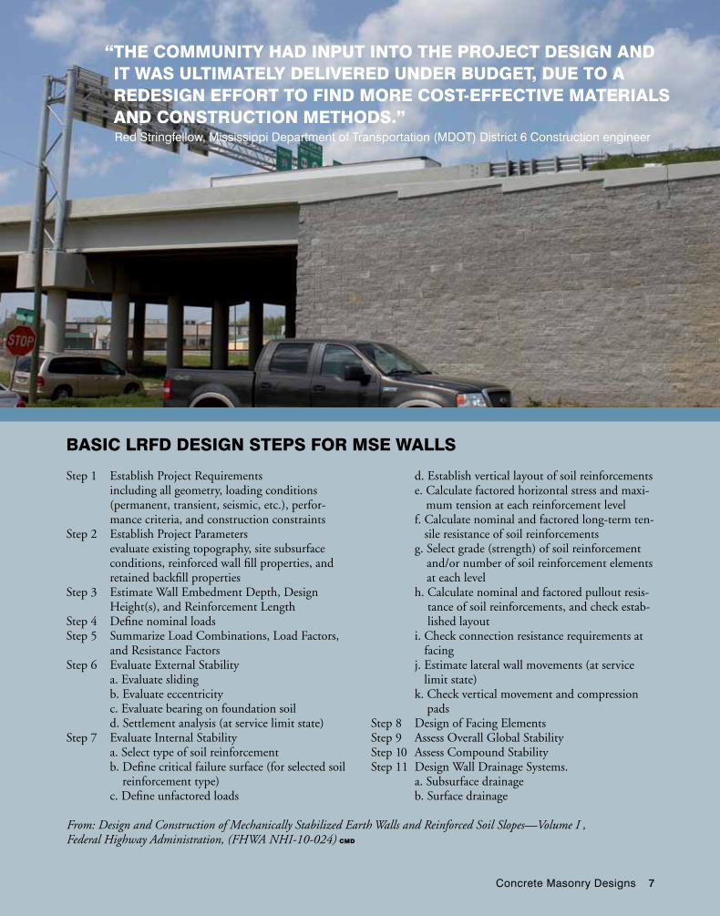
BASIC LRFD DESIgn STEPS FoR MSE WALLS
From: Design and Construction of Mechanically Stabilized Earth Walls and Reinforced Soil Slopes—Volume I , Federal Highway Administration, (FHWA NHI-10-024) CMD
“ THE CoMMunITy HAD InPuT InTo THE PRojECT DESIgn AnD IT WAS uLTIMATELy DELIVERED unDER BuDgET, DuE To A REDESIgn EFFoRT To FInD MoRE CoST-EFFECTIVE MATERIALS AnD ConSTRuCTIon METHoDS.”
Red Stringfellow, Mississippi Department of Transportation (MDOT) District 6 Construction engineer
Step 1 Establish Project Requirements including all geometry, loading conditions
(permanent, transient, seismic, etc.), perfor-mance criteria, and construction constraints
Step 2 Establish Project Parameters evaluate existing topography, site subsurface
conditions, reinforced wall fill properties, and retained backfill properties
Step 3 Estimate Wall Embedment Depth, Design Height(s), and Reinforcement Length
Step 4 Define nominal loadsStep 5 Summarize Load Combinations, Load Factors,
and Resistance FactorsStep 6 Evaluate External Stability a. Evaluate sliding b. Evaluate eccentricity c. Evaluate bearing on foundation soil d. Settlement analysis (at service limit state)Step 7 Evaluate Internal Stability a. Select type of soil reinforcement b. Define critical failure surface (for selected soil
reinforcement type) c. Define unfactored loads
d. Establish vertical layout of soil reinforcements e. Calculate factored horizontal stress and maxi-
mum tension at each reinforcement level f. Calculate nominal and factored long-term ten-
sile resistance of soil reinforcements g. Select grade (strength) of soil reinforcement
and/or number of soil reinforcement elements at each level
h. Calculate nominal and factored pullout resis-tance of soil reinforcements, and check estab-lished layout
i. Check connection resistance requirements at facing
j. Estimate lateral wall movements (at service limit state)
k. Check vertical movement and compression pads
Step 8 Design of Facing ElementsStep 9 Assess Overall Global StabilityStep 10 Assess Compound StabilityStep 11 Design Wall Drainage Systems. a. Subsurface drainage b. Surface drainage
8 Concrete Masonry Designs
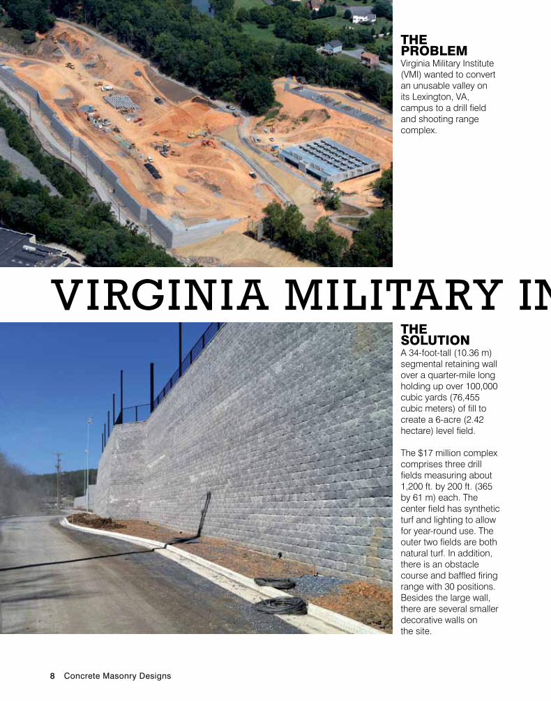
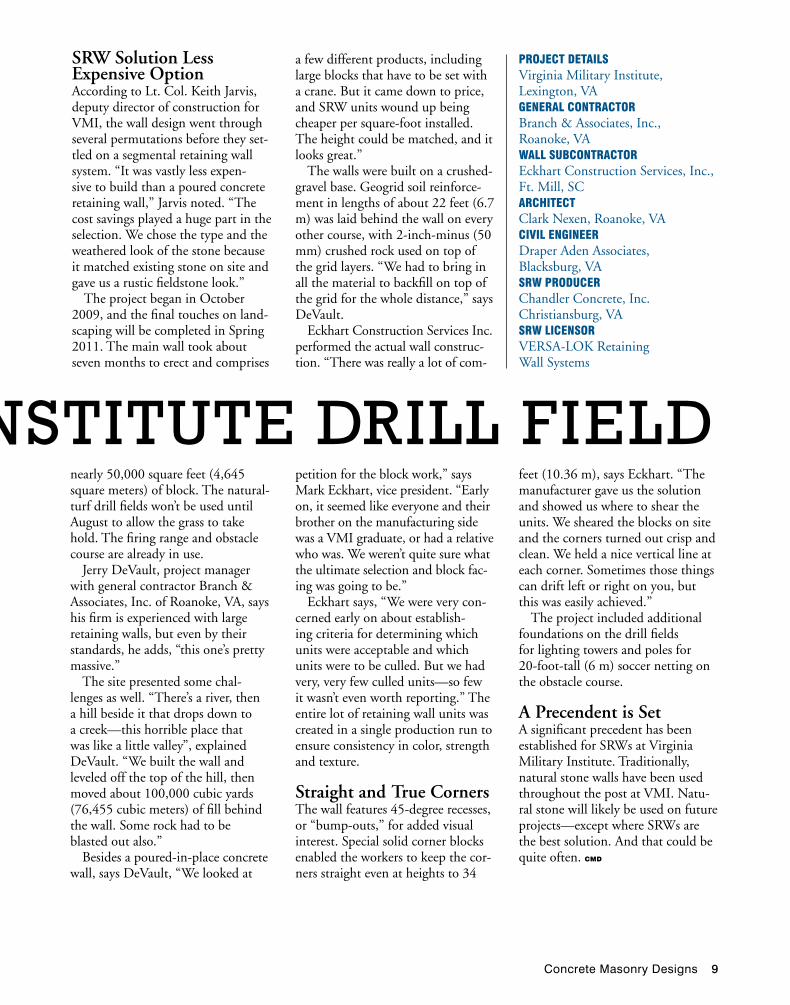
THE PRoBLEM Virginia Military Institute (VMI) wanted to convert an unusable valley on its Lexington, VA, campus to a drill field and shooting range complex.
THE SoLuTIon A 34-foot-tall (10.36 m) segmental retaining wall over a quarter-mile long holding up over 100,000 cubic yards (76,455 cubic meters) of fill to create a 6-acre (2.42 hectare) level field.
The $17 million complex comprises three drill fields measuring about 1,200 ft. by 200 ft. (365 by 61 m) each. The center field has synthetic turf and lighting to allow for year-round use. The outer two fields are both natural turf. In addition, there is an obstacle course and baffled firing range with 30 positions. Besides the large wall, there are several smaller decorative walls on the site.
Virginia Military institute Drill FielD
Concrete Masonry Designs 9
Project DetaiLSVirginia Military Institute, Lexington, VAgeneraL contractorBranch & Associates, Inc., Roanoke, VAwaLL SuBcontractorEckhart Construction Services, Inc., Ft. Mill, SCarchitectClark Nexen, Roanoke, VAciviL engineerDraper Aden Associates, Blacksburg, VASrw ProDucerChandler Concrete, Inc. Christiansburg, VASrw LicenSorVERSA-LOK Retaining Wall Systems
Virginia Military institute Drill FielD
SrW Solution Less expensive OptionAccording to Lt. Col. Keith Jarvis, deputy director of construction for VMI, the wall design went through several permutations before they set-tled on a segmental retaining wall system. “It was vastly less expen-sive to build than a poured concrete retaining wall,” Jarvis noted. “The cost savings played a huge part in the selection. We chose the type and the weathered look of the stone because it matched existing stone on site and gave us a rustic fieldstone look.”
The project began in October 2009, and the final touches on land-scaping will be completed in Spring 2011. The main wall took about seven months to erect and comprises
a few different products, including large blocks that have to be set with a crane. But it came down to price, and SRW units wound up being cheaper per square-foot installed. The height could be matched, and it looks great.”
The walls were built on a crushed-gravel base. Geogrid soil reinforce-ment in lengths of about 22 feet (6.7 m) was laid behind the wall on every other course, with 2-inch-minus (50 mm) crushed rock used on top of the grid layers. “We had to bring in all the material to backfill on top of the grid for the whole distance,” says DeVault.
Eckhart Construction Services Inc. performed the actual wall construc-tion. “There was really a lot of com-
feet (10.36 m), says Eckhart. “The manufacturer gave us the solution and showed us where to shear the units. We sheared the blocks on site and the corners turned out crisp and clean. We held a nice vertical line at each corner. Sometimes those things can drift left or right on you, but this was easily achieved.”
The project included additional foundations on the drill fields for lighting towers and poles for 20-foot-tall (6 m) soccer netting on the obstacle course.
a Precendent is SetA significant precedent has been established for SRWs at Virginia Military Institute. Traditionally, natural stone walls have been used throughout the post at VMI. Natu-ral stone will likely be used on future projects—except where SRWs are the best solution. And that could be quite often. CMD
nearly 50,000 square feet (4,645 square meters) of block. The natural-turf drill fields won’t be used until August to allow the grass to take hold. The firing range and obstacle course are already in use.
Jerry DeVault, project manager with general contractor Branch & Associates, Inc. of Roanoke, VA, says his firm is experienced with large retaining walls, but even by their standards, he adds, “this one’s pretty massive.”
The site presented some chal-lenges as well. “There’s a river, then a hill beside it that drops down to a creek—this horrible place that was like a little valley”, explained DeVault. “We built the wall and leveled off the top of the hill, then moved about 100,000 cubic yards (76,455 cubic meters) of fill behind the wall. Some rock had to be blasted out also.”
Besides a poured-in-place concrete wall, says DeVault, “We looked at
petition for the block work,” says Mark Eckhart, vice president. “Early on, it seemed like everyone and their brother on the manufacturing side was a VMI graduate, or had a relative who was. We weren’t quite sure what the ultimate selection and block fac-ing was going to be.”
Eckhart says, “We were very con-cerned early on about establish-ing criteria for determining which units were acceptable and which units were to be culled. But we had very, very few culled units—so few it wasn’t even worth reporting.” The entire lot of retaining wall units was created in a single production run to ensure consistency in color, strength and texture.
Straight and True CornersThe wall features 45-degree recesses, or “bump-outs,” for added visual interest. Special solid corner blocks enabled the workers to keep the cor-ners straight even at heights to 34
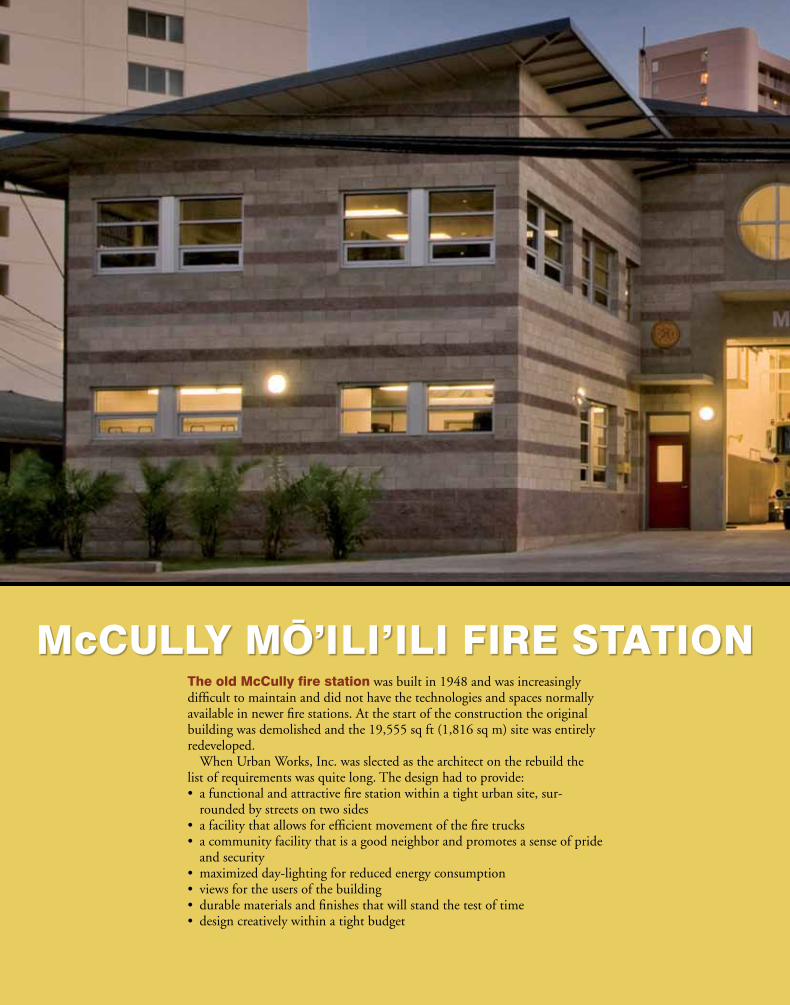
The old McCully fire station was built in 1948 and was increasingly difficult to maintain and did not have the technologies and spaces normally available in newer fire stations. At the start of the construction the original building was demolished and the 19,555 sq ft (1,816 sq m) site was entirely redeveloped.
When Urban Works, Inc. was slected as the architect on the rebuild the list of requirements was quite long. The design had to provide:• afunctionalandattractivefirestationwithinatighturbansite,sur-
rounded by streets on two sides• afacilitythatallowsforefficientmovementofthefiretrucks• acommunityfacilitythatisagoodneighborandpromotesasenseofpride
and security• maximizedday-lightingforreducedenergyconsumption• viewsfortheusersofthebuilding• durablematerialsandfinishesthatwillstandthetestoftime• designcreativelywithinatightbudget
McCuLLy Mo’ILI’ILI FIRE STATIon
12 Concrete Masonry Designs
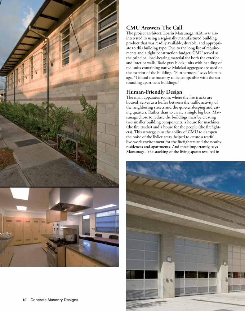
CMu answers The CallThe project architect, Lorrin Matsunaga, AIA, was also interested in using a regionally manufactured building product that was readily available, durable, and appropri-ate to this building type. Due to the long list of require-ments and a tight construction budget, CMU served as the principal load-bearing material for both the exterior and interior walls. Basic gray block units with banding of red units containing native Molokai aggregate are used on the exterior of the building. “Furthermore,” says Matsun-aga, “I found the masonry to be compatible with the sur-rounding apartment buildings.”
Human-Friendly DesignThe main apparatus room, where the fire trucks are housed, serves as a buffer between the traffic activity of the neighboring streets and the quieter sleeping and eat-ing quarters. Rather than to create a single big box, Mat-sunaga chose to reduce the buildings mass by creating two smaller building components: a house for machines (the fire trucks) and a house for the people (the firefight-ers). This strategy, plus the ability of CMU to dampen the noise of the livlier areas, helped to create a restful live-work environment for the firefighters and the nearby residences and apartments. And most importantly, says Matsunaga, “the stacking of the living spaces resulted in
Concrete Masonry Designs 13
Project LocationHonolulu, HawaiiarchitectUrban Works, IncStructuraL engineerSSFM InternationalcontractorAllied ConstructionMaSonry SuPPLierTileco, IncMaSonry contractorAffiliated Construction, LLC
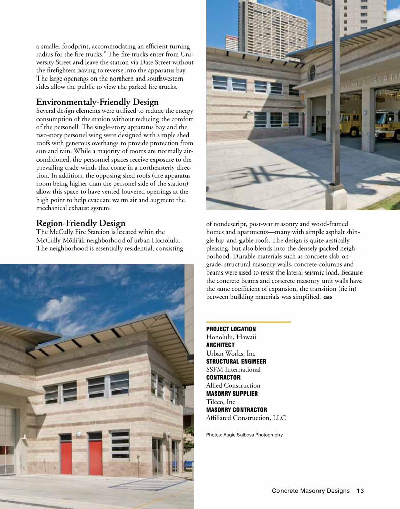
a smaller foodprint, accommodating an efficient turning radius for the fire trucks.” The fire trucks enter from Uni-versity Street and leave the station via Date Street without the firefighters having to reverse into the apparatus bay. The large openings on the northern and southwestern sides allow the public to view the parked fire trucks.
environmentaly-Friendly DesignSeveral design elements were utilized to reduce the energy consumption of the station without reducing the comfort of the personell. The single-story apparatus bay and the two-story personel wing were designed with simple shed roofs with generous overhangs to provide protection from sun and rain. While a majority of rooms are normally air-conditioned, the personnel spaces receive exposure to the prevailing trade winds that come in a northeasterly direc-tion. In addition, the opposing shed roofs (the apparatus room being higher than the personel side of the station) allow this space to have vented louvered openings at the high point to help evacuate warm air and augment the mechanical exhaust system.
region-Friendly DesignThe McCully Fire Stateion is located wihin the McCully-Moili’ili neighborhood of urban Honolulu. The neighborhood is essentially residential, consisting
of nondescript, post-war masonry and wood-framed homes and apartments—many with simple asphalt shin-gle hip-and-gable roofs. The design is quite aestically pleasing, but also blends into the densely packed neigh-borhood. Durable materials such as concrete slab-on-grade, structural masonry walls, concrete columns and beams were used to resist the lateral seismic load. Because the concrete beams and concrete masonry unit walls have the same coefficient of expansion, the transition (tie in) between building materials was simplified. CMD
Photos: Augie Salbosa Photography
14 Concrete Masonry Designs
Recent fires in homes with mid-rise wood frame buildings have brought into focus the issue of
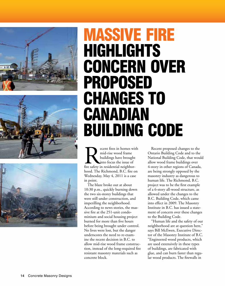
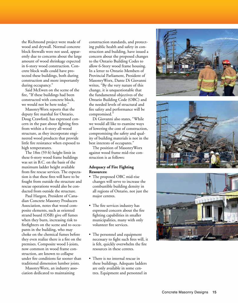
fire safety in residential neighbor-hood. The Richmond, B.C. fire on Wednesday, May 4, 2011 is a case in point.
The blaze broke out at about 10:30 p.m., quickly burning down the two six-storey buildings that were still under construction, and imperilling the neighborhood. According to news stories, the mas-sive fire at the 251-unit condo-minium and social housing project burned for more than five hours before being brought under control. No lives were lost, but the danger underscores the need to re-exam-ine the recent decision in B.C. to allow mid-rise wood frame construc-tion, instead of the long-required fire resistant masonry materials such as concrete block.
MaSSive Fire highLightS concern over ProPoSeD changeS to canaDian BuiLDing coDe
Recent proposed changes to the Ontario Building Code and to the National Building Code, that would allow wood frame buildings over 4-story in other regions of Canada, are being strongly opposed by the masonry industry as dangerous to human life. The Richmond, B.C. project was to be the first example of a 6-story all-wood structure, as allowed under the changes to the B.C. Building Code, which came into effect in 2009. The Masonry Institute in B.C. has issued a state-ment of concern over these changes to the Building Code.
“Human life and the safety of our neighborhood are at question here,” says Bill McEwen, Executive Direc-tor of the Masonry Institute of B.C. “Engineered wood products, which are used extensively in these types of buildings, are fabricated with glue, and can burn faster than regu-lar wood products. The firewalls in
Concrete Masonry Designs 15
the Richmond project were made of wood and drywall. Normal concrete block firewalls were not used, appar-ently due to concerns about the large amount of wood shrinkage expected in 6-story wood construction. Con-crete block walls could have pro-tected these buildings, both during construction and more importantly during occupancy.”
Said McEwen on the scene of the fire, “If these buildings had been constructed with concrete block, we would not be here today.”
MasonryWorx reports that the deputy fire marshal for Ontario, Doug Crawford, has expressed con-cern in the past about fighting fires from within a 6-story all-wood structure, as they incorporate engi-neered wood products that provide little fire resistance when exposed to high temperatures.
The 18m (59 ft) height limit in these 6-story wood frame buildings was set in B.C. on the basis of the maximum ladder height available from fire rescue services. The expecta-tion is that these fires will have to be fought from outside the structure and rescue operations would also be con-ducted from outside the structure.
Paul Hargest, President of Cana-dian Concrete Masonry Producers Association, notes that wood com-posite elements, such as oriented strand board (OSB) give off fumes when they burn, increasing risk to firefighters on the scene and to occu-pants in the building, who may choke on the chemical fumes before they even realize there is a fire on the premises. Composite wood I-joists, now common in wood frame con-struction, are known to collapse under fire conditions far sooner than traditional dimension lumber joists.
MasonryWorx, an industry asso-ciation dedicated to maintaining
construction standards, and protect-ing public health and safety in con-struction and building, have issued a concern about the proposed changes to the Ontario Building Codes to allow 6-Story wood frame housing. In a letter to Ontario Members of Provincial Parliament, President of MasonryWorx, Dante Di Giovanni writes, “By the very nature of this change, it is unquestionable that the fundamental objectives of the Ontario Building Code (OBC) and the needed levels of structural and fire safety and performance will be compromised.”
Di Giovanni also states, “While we would all like to examine ways of lowering the cost of construction, compromising the safety and qual-ity of building materials is not in the best interests of occupants.”
The position of MasonryWorx against wood frame mid-rise con-struction is as follows:
Adequacy of Fire Fighting Resources:• TheproposedOBCmid-rise
changes will serve to increase the combustible building density in all regions of Ontario, not just the major centres.
• Thefireservicesindustryhasexpressed concern about the fire fighting capabilities in smaller municipalities, many with only volunteer fire services.
• Thepersonnelandequipmentnecessary to fight such fires will, it is felt, quickly overwhelm the fire resources in these centres.
• Thereisnointernalrescueinthese buildings. Adequate ladders are only available in some cen-tres. Equipment and personnel in
16 Concrete Masonry Designs
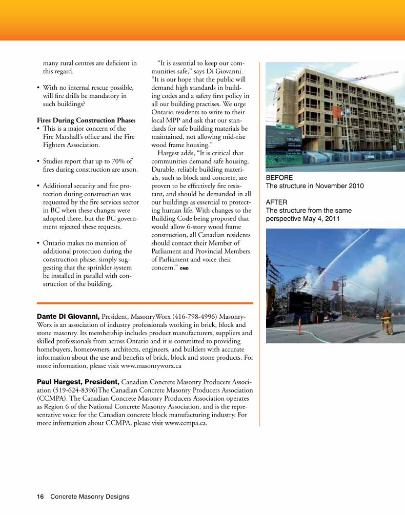
BEFORE The structure in November 2010
AFTER The structure from the same perspective May 4, 2011
many rural centres are deficient in this regard.
• Withnointernalrescuepossible,will fire drills be mandatory in such buildings?
Fires During Construction Phase:• Thisisamajorconcernofthe
Fire Marshall’s office and the Fire Fighters Association.
• Studiesreportthatupto70%offires during construction are arson.
• Additionalsecurityandfirepro-tection during construction was requested by the fire services sector in BC when these changes were adopted there, but the BC govern-ment rejected these requests.
• Ontariomakesnomentionofadditional protection during the construction phase, simply sug-gesting that the sprinkler system be installed in parallel with con-struction of the building.
“It is essential to keep our com-munities safe,” says Di Giovanni. “It is our hope that the public will demand high standards in build-ing codes and a safety first policy in all our building practises. We urge Ontario residents to write to their local MPP and ask that our stan-dards for safe building materials be maintained, not allowing mid-rise wood frame housing.”
Hargest adds, “It is critical that communities demand safe housing. Durable, reliable building materi-als, such as block and concrete, are proven to be effectively fire resis-tant, and should be demanded in all our buildings as essential to protect-ing human life. With changes to the Building Code being proposed that would allow 6-story wood frame construction, all Canadian residents should contact their Member of Parliament and Provincial Members of Parliament and voice their concern.” CMD
Dante Di giovanni, President, MasonryWorx (416-798-4996) Masonry-Worx is an association of industry professionals working in brick, block and stone masonry. Its membership includes product manufacturers, suppliers and skilled professionals from across Ontario and it is committed to providing homebuyers, homeowners, architects, engineers, and builders with accurate information about the use and benefits of brick, block and stone products. For more information, please visit www.masonryworx.ca
Paul Hargest, President, Canadian Concrete Masonry Producers Associ-ation (519-624-8396)The Canadian Concrete Masonry Producers Association (CCMPA). The Canadian Concrete Masonry Producers Association operates as Region 6 of the National Concrete Masonry Association, and is the repre-sentative voice for the Canadian concrete block manufacturing industry. For more information about CCMPA, please visit www.ccmpa.ca.
NCMA TEK 5-5B 1
A n i n f o r m a t i o n s e r i e s f r o m t h e n a t i o n a l a u t h o r i t y o n c o n c r e t e m a s o n r y t e c h n o l o g y
INTEGRATING CONCRETE MASONRY WALLSWITH METAL BUILDING SYSTEMS
TEK 5-5BDetails (2011)
INTRODUCTION
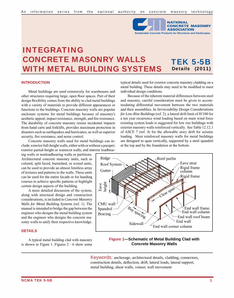
Metal buildings are used extensively for warehouses and other structures requiring large, open floor spaces. Part of their design flexibility comes from the ability to clad metal buildings with a variety of materials to provide different appearances or functions to the buildings. Concrete masonry walls are popular enclosure systems for metal buildings because of masonry's aesthetic appeal, impact resistance, strength, and fire resistance. The durability of concrete masonry resists incidental impacts from hand carts and forklifts, provides maximum protection in disasters such as earthquakes and hurricanes, as well as superior security, fire resistance, and noise control. Concrete masonry walls used for metal buildings can in-clude: exterior full-height walls, either with or without a parapet; exterior partial-height or wainscot walls; and interior loadbear-ing walls or nonloadbearing walls or partitions. Architectural concrete masonry units, such as colored, split faced, burnished, or scored units, can be used to provide an almost limitless array of textures and patterns to the walls. These units can be used for the entire facade or for banding courses to achieve specific patterns or highlight certain design aspects of the building. A more detailed discussion of the system, along with structural design and construction considerations, is included in Concrete Masonry Walls for Metal Building Systems (ref. 1). The manual is intended to bridge the gap between the engineer who designs the metal building system and the engineer who designs the concrete ma-sonry walls to unify their respective knowledge.
DETAILS
A typical metal building clad with masonry is shown in Figure 1. Figures 2 - 6 show some
typical details used for exterior concrete masonry cladding on a metal building. These details may need to be modified to meet individual design conditions. Because of the inherent material differences between steel and masonry, careful consideration must be given to accom-modating differential movement between the two materials and their assemblies. In Serviceability Design Considerations for Low-Rise Buildings (ref. 2), a lateral drift limit of H/100 for a ten year recurrence wind loading based on main wind force resisting system loads is suggested for low rise buildings with exterior masonry walls reinforced vertically. See Table 12.12.1 of ASCE 7 (ref. 4) for the allowable story drift for seismic loading. Most reinforced masonry walls for metal buildings are designed to span vertically, supported by a steel spandrel at the top and by the foundation at the bottom.
Keywords: anchorage, architectural details, cladding, connectors, construction details, deflection, drift, lateral loads, lateral support, metal building, shear walls, veneer, wall movement
Figure 1—Schematic of Metal Building Clad withConcrete Masonry Walls
Roof purlinEave strutRigid framecolumnRigid frame
End wallEnd wall roof beam
End wall columnEnd wall frame
End wall corner column
RidgeRoof SystemGutter
BracingSpandrelCMU wall
Sidewall
Clear span
Bay spacing
Eave
heig
ht
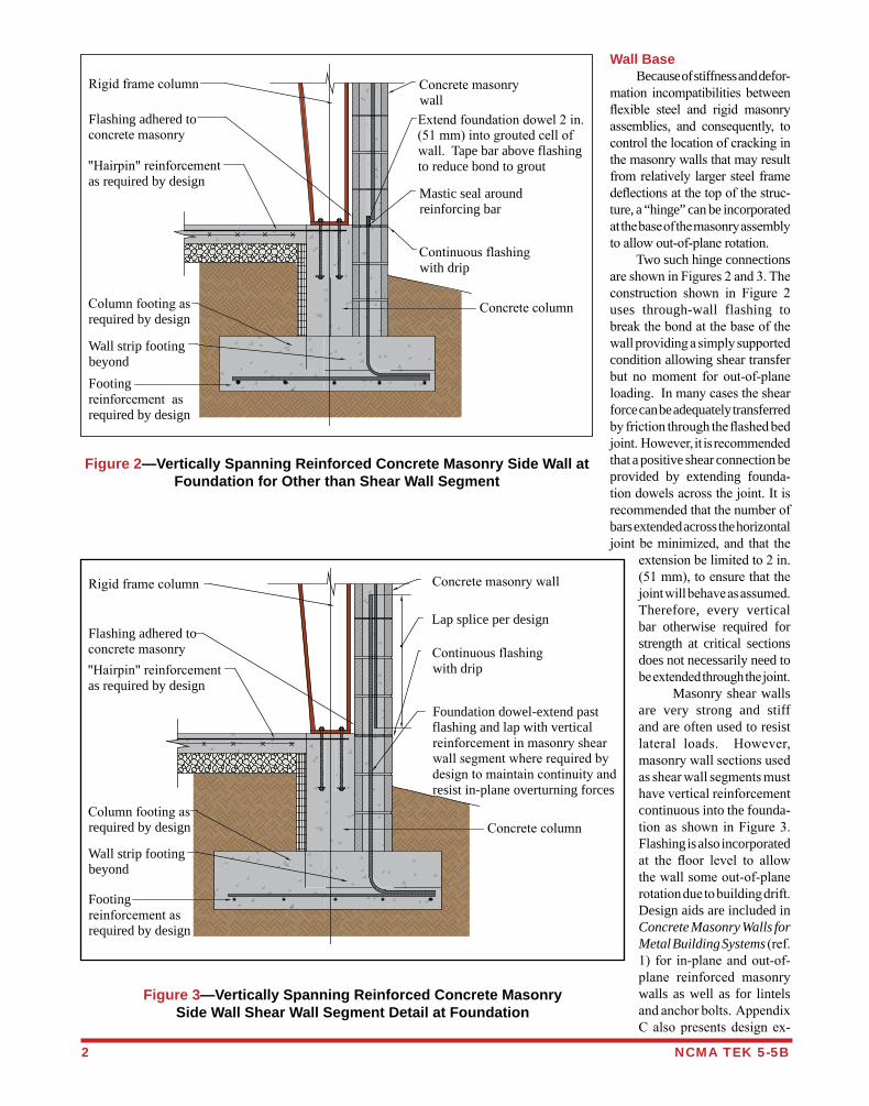
Wall Base Because of stiffness and defor-mation incompatibilities between flexible steel and rigid masonry assemblies, and consequently, to control the location of cracking in the masonry walls that may result from relatively larger steel frame deflections at the top of the struc-ture, a “hinge” can be incorporated at the base of the masonry assembly to allow out-of-plane rotation. Two such hinge connections are shown in Figures 2 and 3. The construction shown in Figure 2 uses through-wall flashing to break the bond at the base of the wall providing a simply supported condition allowing shear transfer but no moment for out-of-plane loading. In many cases the shear force can be adequately transferred by friction through the flashed bed joint. However, it is recommended that a positive shear connection be provided by extending founda-tion dowels across the joint. It is recommended that the number of bars extended across the horizontal joint be minimized, and that the
extension be limited to 2 in. (51 mm), to ensure that the joint will behave as assumed. Therefore, every vertical bar otherwise required for strength at critical sections does not necessarily need to be extended through the joint. Masonry shear walls are very strong and stiff and are often used to resist lateral loads. However, masonry wall sections used as shear wall segments must have vertical reinforcement continuous into the founda-tion as shown in Figure 3. Flashing is also incorporated at the floor level to allow the wall some out-of-plane rotation due to building drift. Design aids are included in Concrete Masonry Walls for Metal Building Systems (ref. 1) for in-plane and out-of-plane reinforced masonry walls as well as for lintels and anchor bolts. Appendix C also presents design ex-
2 NCMA TEK 5-5B
Figure 2—Vertically Spanning Reinforced Concrete Masonry Side Wall at Foundation for Other than Shear Wall Segment
Continuous flashingwith drip
Concrete masonrywall
Footingreinforcement asrequired by design
Wall strip footingbeyond
Column footing asrequired by design
Flashing adhered toconcrete masonry
Rigid frame column
"Hairpin" reinforcementas required by design
Extend foundation dowel 2 in.(51 mm) into grouted cell ofwall. Tape bar above flashingto reduce bond to grout
Mastic seal aroundreinforcing bar
Concrete column
Figure 3—Vertically Spanning Reinforced Concrete Masonry Side Wall Shear Wall Segment Detail at Foundation
Continuous flashingwith drip
Concrete masonry wall
Footingreinforcement asrequired by design
Wall strip footingbeyond
Column footing asrequired by design
Flashing adhered toconcrete masonry
Rigid frame column
"Hairpin" reinforcementas required by design
Lap splice per design
Foundation dowel-extend pastflashing and lap with verticalreinforcement in masonry shearwall segment where required bydesign to maintain continuity andresist in-plane overturning forces
Concrete column
NCMA TEK 18-1B 1
A n i n f o r m a t i o n s e r i e s f r o m t h e n a t i o n a l a u t h o r i t y o n c o n c r e t e m a s o n r y t e c h n o l o g y
EVALUATING THE COMPRESSIVE STRENGTH OF CONCRETE MASONRY
TEK 18-1BQuality Assurance & Testing (2011)
INTRODUCTION
Structural performance of concrete masonry is largely dependent upon three key criteria:• theengineeringrationaleincorporatedintothedesign
of the structure;• thephysicalcharacteristicsofthematerialsusedinthe
construction of the structure (i.e., the masonry units, grout, mortar, and reinforcement); and
• thequalityoftheconstructionusedinassemblingthesecomponents.
Thefirststepinthedesignofanyengineeredmasonrystructure is determining anticipated service loads. Once theseloadsareestablished,therequiredstrengthofthemasonrycanbedetermined.Thedesignationf'm, indicates thespecifiedcompressivestrengthofmasonry.Itisusedthroughout the design and, in accordance with the ap-propriatecode,topredictthestrengthandbehaviorofthemasonryassemblyandthustosizemasonryelements.Itshouldbestressedthatthespecifiedcompressivestrengthofthemasonryisrelatedtobutnotequaltothetestedcompressive strength of the masonry. Toensurethatasafeandfunctionalstructureisbeingconstructed that will meet or exceed the intended service life,measuresmustbetakentoverifythatthecompressivestrengthoftheassembledmaterials,includingmasonryunits, mortar and grout if used, meet or exceed the speci-fiedcompressivestrengthofthemasonry. Compliancewiththespecifiedcompressivestrengthisverifiedbyoneoftwomethods:theunitstrengthmethodor the prism test method. These two methods are refer-encedinmasonrydesigncodes(refs.1,4),specifications(ref. 2), and standards (ref. 3) as rational procedures for verifying masonry compressive strength.
UNIT STRENGTH METHOD
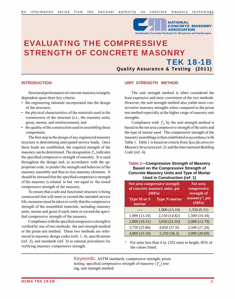
The unit strength method is often considered the least expensive and most convenient of the two methods. However, the unit strength method also yields more con-servative masonry strengths when compared to the prism test method especially at the higher range of masonry unit strengths. Compliance with f'mbytheunitstrengthmethodisbasedonthenetareacompressivestrengthoftheunitsandthe type of mortar used. The compressive strength of the masonryassemblageisthenestablishedinaccordancewithTable1.Table1isbasedoncriteriafromSpecification for Masonry Structures (ref. 2) and the International Building Code (ref. 4).
Keywords: ASTM standards, compressive strength, prism testing,specifiedcompressivestrengthofmasonry(f'm) test-ing, unit strength method
Table 1—Compressive Strength of Masonry Based on the Compressive Strength of
Concrete Masonry Units and Type of Mortar Used in Construction (ref. 1)
Net area compressive strength of concrete masonry units, psi
(MPa)
Net area compressive strength of
masonryA, psi (MPa)
Type M or S mortar
Type N mortar
---- 1,900 (13.10) 1,350 (9.31)1,900 (13.10) 2,150 (14.82) 1,500 (10.34)2,800 (19.31) 3,050 (21.03) 2,000 (13.79)3,750 (25.86) 4,050 (27.92 2,500 (17.24)4,800 (33.10) 5,250 (36.2) 3,000 (20.69)
A For units less than 4 in. (102 mm) in height, 85% of the values listed.
Conversely, if the concrete masonry units have compres-sive strengths of 2,800 psi (19.3 MPa), then the maximum f'musedindesignwouldbe2,000psi(13.8MPa)ifTypeM or S mortar were used. Similarly, if 3,050 psi (21.0 MPa) concrete masonry were used in conjunction with Type N mortar, the maximum f'mthatcouldbeusedindesignwouldalsobe2,000psi(13.8MPa).NotethatperfootnoteAofTable1,compressivestrengthofmasonryvaluesmustbemultipliedby85%whentheunitstrengthisestablishedonunitslessthan4in.(102mm)inheight. When higher strength masonry materials are speci-fied,itusuallyismorecosteffectivetoutilizetheprismtest method to demonstrate compliance with f'm due to the level of conservatism inherent in the unit strength method; i.e.,thecostsoftestingarewelloffsetbytheconstructionsavings resulting from a more economical design that takes advantage of using a higher compressive strength for the samespecifiedmaterials.
PRISM TEST METHOD
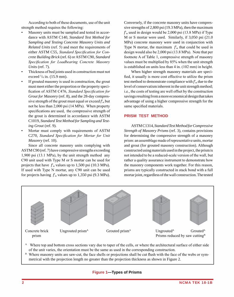
ASTM C1314, Standard Test Method for Compressive Strength of Masonry Prisms (ref. 3), contains provisions for determining the compressive strength of a masonry prism:anassemblagemadeofrepresentativeunits,mortarand grout (for grouted masonry construction). Although constructed using materials used in the project, the prism is notintendedtobeareduced-scaleversionofthewall,butratheraqualityassuranceinstrumenttodemonstratehowthe masonry components work together. For this reason, prismsaretypicallyconstructedinstackbondwithafullmortar joint, regardless of the wall construction. The tested
Accordingtobothofthesedocuments,useoftheunitstrengthmethodrequiresthefollowing:• Masonryunitsmustbesampledandtestedinaccor-
dance with ASTM C140, Standard Test Method for Sampling and Testing Concrete Masonry Units and Related Units(ref.5)andmeettherequirementsofeither ASTM C55, Standard Specification for Con-crete Building Brick (ref. 6) or ASTM C90, Standard Specification for Loadbearing Concrete Masonry Units (ref. 7).
• Thicknessofbedjointsusedinconstructionmustnotexceed 5/8 in. (15.9 mm).
• Ifgroutedmasonryisusedinconstruction,thegroutmust meet either the proportion or the property speci-ficationofASTMC476,Standard Specification for Grout for Masonry (ref. 8), and the 28-day compres-sivestrengthofthegroutmustequalorexceedf'mbutnotbelessthan2,000psi(14MPa).Whenpropertyspecificationsareused,thecompressivestrengthofthe grout is determined in accordance with ASTM C1019, Standard Test Method for Sampling and Test-ing Grout (ref. 9).
• Mortarmust complywith requirements ofASTMC270, Standard Specification for Mortar for Unit Masonry (ref. 10).
Since all concrete masonry units complying with ASTM C90 (ref. 7) have compressive strengths exceeding 1,900psi(13.1MPa),bytheunitstrengthmethodanyC90unitusedwithTypeMorSmortarcanbeusedforprojects that have f'm values up to 1,500 psi (10.3 MPa). IfusedwithTypeNmortar,anyC90unitcanbeusedfor projects having f'm values up to 1,350 psi (9.3 MPa).
Figure 1—Types of Prisms
2 NCMA TEK 18-1B
Concretebrick UngroutedprismA Grouted prismA UngroutedA GroutedA
prism PrismsreducedbysawcuttingB
A Wheretopandbottomcrosssectionsvaryduetotaperofthecells,orwherethearchitecturalsurfaceofeithersideoftheunitvaries,theorientationmustbethesameasusedinthecorrespondingconstruction.
B Wheremasonryunitsaresaw-cut,thefaceshellsorprojectionsshallbecutflushwiththefaceofthewebsorsym-metrical with the projection length no greater than the projection thickness as shown in Figure 2.
Concretebrickprism
Ungroutedprism Grouted prisma Ungroutedprisma Ungroutedprisma
Prismsreducedbysawcuttingb
Wheretopandbottomcrosssectionsvaryduetotaperofthecells,orwherethe architectural surfaceofeithersideoftheunitvaries,theorientationsshallbethe same as used in the corresponding construction.Wheremasonryunitsaresawcut,thefaceshellsorprojectionsshallbecutflushwiththefaceofthewebsorsymetricalwiththeprojectionlengthnogreaterthan the projection thickness as shown in Figure 2.
a
b
a
NCMA TEK 18-1B 3
Figure 2—Saw-Cut Locations for Reduced-Size Prisms
compressive strength of the prism is corrected to account fordifferentpermissibleheighttothicknessratiosoftheprisms.Thiscorrectedstrengthmustequalorexceedf'm. Understandably,prismtestingshouldbeundertakenbeforeconstructionbeginstoverifythatthecompressivestrengthoftheassembledmaterialsisnotlessthanthespecifiedcompressive strength used in the design. Prismsshouldbe28daysoldtodocumentcompliancewith f'm, When prisms are tested as part of an inspection program periodically during the course of construction, an earlier age, such as 3 or 7 days, is often preferred. To confidentlyinterprettheresultsoftheseearlierageprismtests, the relationship between prism age and strengthdevelopmentshouldbedeterminedusingthematerials,constructionmethodsandtestingprocedurestobeusedthroughoutthejob.Onlywhenthisstrength/timecurveisgeneratedcanearlyagetestresultsbeextrapolatedtopredict the 28-day strength.
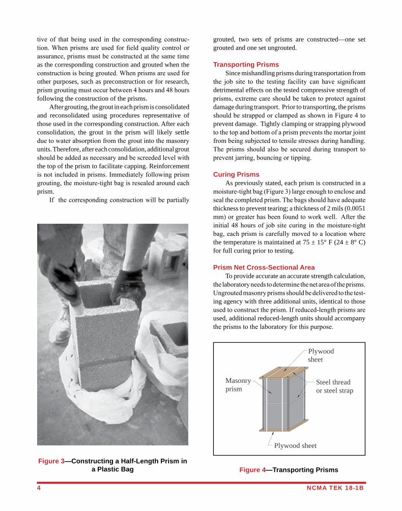
Prism Construction Masonry prisms are constructed using units represen-tativeofthosebeingusedintheconstruction.Onesetofprisms (containing three individual prisms) is constructed foreachcombinationofmaterialsandeachtestingageforwhichthecompressivestrengthistobedetermined.Formulti-wythe masonry construction, with different units ormortarineachwythe,separateprismsshouldbebuiltrepresentative of each wythe, and tested separately. Prisms shouldbeconstructedonaflatandlevellocationwheretheycanremainundisturbeduntiltheyaretransportedfortesting, at least 48 hours. Allunitsusedtoconstructtheprismsmustbeofthesameconfigurationandorientedinthesamewaysothatwebsandfaceshellsarealignedoneontopoftheother.Unitsarelaidinstackbondonafullmortarbedusingmortar representative of that used in the corresponding construction. Mortar joints are cutflush regardlessofthe type of mortar joint tooling used in the construction. Prisms composed of units that contain closed cells must have at least one complete cell with one full-width cross weboneitherend.Variousprismconfigurationsareshownin Figure 1. Sincemasonryprismscanbeheavy,especiallygroutedprisms, it often proves effective to construct prisms using half-length units. The criteria for constructing prisms of reduced-sizedunitsare(alsoseeFigure2):• thathollowunitscontainfullyclosedcells,• thatthecrosssectionisassymmetricalaspossible,and• thatthelengthisnotlessthan4in.(102mm). As a result, handling, transporting, capping, and testing the reduced sized prisms is easier, resulting inlesspotentialfordamagetotheprisms.Usingreduced-
lengthprismsalsoreducestherequiredplatethicknessesfor compression machines and typically result in higher and more accurate assessments of masonry strengths. Immediately followingconstructionof theprisms,eachprism is sealed inamoisture-tightbag,asshowninFigure3.Theprismtestmethodrequiresprismstobecuredinsealedplasticbagstoensureuniformhydrationofthemortarandthegroutifused.Underactualfieldconditions, itmayrequire longerperiods forhydrationandthecorrespondingstrengthstobeachieved.Curingprismsinsealedplasticbagsresultsinmeasuredstrengthswhicharerepresentativeofthoseexhibitedbythemasonrythroughout the life of the structure. Bag curing also pro-videsauniformandrepeatabletestingprocedure. Wherethecorrespondingconstructionistobegroutedsolid, each prism is grouted solid using grout representa-
x x
Saw-cut
Discard
Where:x < t
Saw-cut
Discard
Portionused in testing
Discard
t
Portionused in testing
Portionused in testing
FS
FS
4 NCMA TEK 18-1B
tive of that being used in the corresponding construc-tion.Whenprismsareused forfieldqualitycontrolorassurance,prismsmustbeconstructedatthesametimeas the corresponding construction and grouted when the constructionisbeinggrouted.Whenprismsareusedforother purposes, such as preconstruction or for research, prismgroutingmustoccurbetween4hoursand48hoursfollowing the construction of the prisms. After grouting, the grout in each prism is consolidated and reconsolidated using procedures representative of those used in the corresponding construction. After each consolidation, the grout in the prism will likely settle duetowaterabsorptionfromthegroutintothemasonryunits. Therefore, after each consolidation, additional grout shouldbeaddedasnecessaryandbescreededlevelwiththe top of the prism to facilitate capping. Reinforcement isnotincludedinprisms.Immediatelyfollowingprismgrouting,themoisture-tightbagisresealedaroundeachprism. If thecorrespondingconstructionwillbepartially
grouted, two sets of prisms are constructed—one set grouted and one set ungrouted.
Transporting Prisms Since mishandling prisms during transportation from the job site to the testing facility can have significantdetrimental effects on the tested compressive strength of prisms,extremecareshouldbetakentoprotectagainstdamage during transport. Prior to transporting, the prisms shouldbestrappedorclampedasshowninFigure4toprevent damage. Tightly clamping or strapping plywood tothetopandbottomofaprismpreventsthemortarjointfrombeingsubjectedtotensilestressesduringhandling.The prisms should also be secured during transport topreventjarring,bouncingortipping.
Curing Prisms As previously stated, each prism is constructed in a moisture-tightbag(Figure3)largeenoughtoencloseandsealthecompletedprism.Thebagsshouldhaveadequatethickness to prevent tearing; a thickness of 2 mils (0.0051 mm)orgreaterhasbeenfoundtoworkwell.Aftertheinitial48hoursof jobsitecuring in themoisture-tightbag,eachprismiscarefullymovedtoalocationwherethe temperature is maintained at 75 ± 15° F (24 ± 8° C) for full curing prior to testing.
Prism Net Cross-Sectional Area To provide accurate an accurate strength calculation, thelaboratoryneedstodeterminethenetareaoftheprisms.Ungroutedmasonryprismsshouldbedeliveredtothetest-ing agency with three additional units, identical to those usedtoconstructtheprism.Ifreduced-lengthprismsareused, additional reduced-length units should accompany theprismstothelaboratoryforthispurpose.
Figure 4—Transporting PrismsFigure 3—Constructing a Half-Length Prism in
a Plastic Bag
Plywoodsheet
Steel threador steel strap
Plywood sheet
Masonryprism
NCMA TEK 18-1B 5
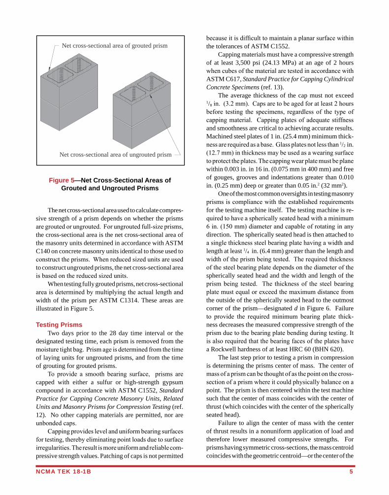
The net cross-sectional area used to calculate compres-sive strength of a prism depends on whether the prisms aregroutedorungrouted.Forungroutedfull-sizeprisms,the cross-sectional area is the net cross-sectional area of the masonry units determined in accordance with ASTM C140 on concrete masonry units identical to those used to constructtheprisms.Whenreducedsizedunitsareusedto construct ungrouted prisms, the net cross-sectional area isbasedonthereducedsizedunits. When testing fully grouted prisms, net cross-sectional areaisdeterminedbymultiplyingtheactuallengthandwidth of the prism per ASTM C1314. These areas are illustrated in Figure 5.
Testing Prisms Two days prior to the 28 day time interval or the designated testing time, each prism is removed from the moisturetightbag.Prismageisdeterminedfromthetimeof laying units for ungrouted prisms, and from the time of grouting for grouted prisms. To provide a smooth bearing surface, prisms arecapped with either a sulfur or high-strength gypsum compound in accordance with ASTM C1552, Standard Practice for Capping Concrete Masonry Units, Related Units and Masonry Prisms for Compression Testing (ref. 12). No other capping materials are permitted, nor are unbondedcaps. Cappingprovideslevelanduniformbearingsurfacesfortesting,therebyeliminatingpointloadsduetosurfaceirregularities.Theresultismoreuniformandreliablecom-pressive strength values. Patching of caps is not permitted
Figure 5—Net Cross-Sectional Areas of Grouted and Ungrouted Prisms
becauseitisdifficulttomaintainaplanarsurfacewithinthe tolerances of ASTM C1552. Capping materials must have a compressive strength of at least 3,500 psi (24.13 MPa) at an age of 2 hours whencubesofthematerialaretestedinaccordancewithASTM C617, Standard Practice for Capping Cylindrical Concrete Specimens (ref. 13). The average thickness of the cap must not exceed 1/8in.(3.2mm).Capsaretobeagedforatleast2hoursbefore testing the specimens, regardlessof the typeofcappingmaterial. Cappingplatesofadequatestiffnessand smoothness are critical to achieving accurate results. Machined steel plates of 1 in. (25.4 mm) minimum thick-nessarerequiredasabase.Glassplatesnotlessthan1/2 in. (12.7mm)inthicknessmaybeusedasawearingsurfacetoprotecttheplates.Thecappingwearplatemustbeplanewithin 0.003 in. in 16 in. (0.075 mm in 400 mm) and free of gouges, grooves and indentations greater than 0.010 in. (0.25 mm) deep or greater than 0.05 in.2 (32 mm2). One of the most common oversights in testing masonry prismsiscompliancewiththeestablishedrequirementsfor the testing machine itself. The testing machine is re-quiredtohaveasphericallyseatedheadwithaminimum6in.(150mm)diameterandcapableofrotatinginanydirection. The spherically seated head is then attached to asinglethicknesssteelbearingplatehavingawidthandlength at least 1/4 in. (6.4 mm) greater than the length and widthoftheprismbeingtested.Therequiredthicknessofthesteelbearingplatedependsonthediameterofthespherically seated head and the width and length of the prismbeing tested. The thicknessof the steelbearingplatemustequalorexceedthemaximumdistancefromthe outside of the spherically seated head to the outmost corner of the prism—designated d in Figure 6. Failure to provide the required minimum bearing plate thick-ness decreases the measured compressive strength of the prismduetothebearingplatebendingduringtesting.Itisalsorequiredthatthebearingfacesoftheplateshavea Rockwell hardness of at least HRC 60 (BHN 620). The last step prior to testing a prism in compression is determining the prisms center of mass. The center of massofaprismcanbethoughtofasthepointonthecross-sectionofaprismwhereitcouldphysicallybalanceonapoint. The prism is then centered within the test machine such that the center of mass coincides with the center of thrust (which coincides with the center of the spherically seated head). Failure to align the center of mass with the center of thrust results in a nonuniform application of load and therefore lower measured compressive strengths. For prisms having symmetric cross-sections, the mass centroid coincides with the geometric centroid—or the center of the
Net cross-sectional area of grouted prism
Net cross-sectional area of ungrouted prism
6 NCMA TEK 18-1B
prism as measured with a ruler. For prisms that are non-symmetricalaboutanaxis,thelocationofthataxiscanbedeterminedbybalancingthemasonryunitonaknifeedgeorametalrodplacedparalleltothataxis.Ifametalrodisused,therodmustbestraight,cylindrical(abletorollfreelyonaflatsurface),haveadiameterbetween1/4 in. and 3/4in.(6.4and19.1mm),anditmustbelongerthan the specimen. Once determined, the centroidal axis canbemarkedontheendoftheprism. To test the prism, it is placed in the compression ma-chinewithbothcentroidalaxesofthespecimenalignedwith the machine's center of thrust. The maximum load and type of fracture is recorded. Prism strength is calculated fromthemaximumloaddividedbytheprismnetarea.Thisprismstrengthisthencorrectedasdescribedbelow.
Corrections for Prism Aspect Ratio Since the ratio of height, hp, to least lateral dimen-sion, tp,—designated the aspect ratio or hp/tp—of the prism cansignificantlyaffecttheloadcarryingcapacityofthemasonry prism, ASTM C1314 contains correction factors for prisms having different aspect ratios, as outlined in Table2. Touse thevalues inTable2, simplymultiply themeasuredcompressivestrengthoftheprismbythecor-rection factor corresponding to the aspect ratio for that prism.CorrectionfactorsshowninTable3canbelinearlyinterpolatedbetweenvalues,butcannotbeextrapolatedfor aspect ratios less than 1.3 or greater than 5.0.
PRISMS FROM EXISTING CONSTRUCTION
Themajorityofqualityassurancetestingofconcretemasonry materials is conducted on samples representative ofthoseusedintheconstruction.Insomecases,however,itmaybenecessaryordesirabletoevaluatethepropertiesof existing masonry construction using the actual construc-tion materials instead of representative samples. Examples where the in-place (in-situ) masonry properties might need
Table 2—Prism Aspect Ratio Correction Factors (ref. 3)
hp/tp: Correction factor:1.3 0.751.5 0.862.0 1.002.5 1.043.0 1.074.0 1.155.0 1.22
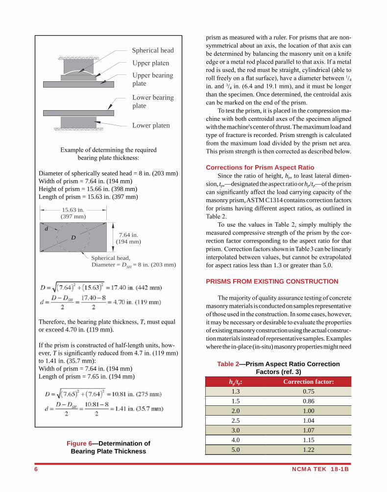
Exampleofdeterminingtherequiredbearingplatethickness:
Diameter of spherically seated head = 8 in. (203 mm)Width of prism = 7.64 in. (194 mm)Height of prism = 15.66 in. (398 mm)Length of prism = 15.63 in. (397 mm)
Therefore,thebearingplatethickness,T,mustequalor exceed 4.70 in. (119 mm).
Iftheprismisconstructedofhalf-lengthunits,how-ever, Tissignificantlyreducedfrom4.7in.(119mm)to 1.41 in. (35.7 mm):Width of prism = 7.64 in. (194 mm)Length of prism = 7.65 in. (194 mm)
Figure 6—Determination of Bearing Plate Thickness
Spherical head
Upperplaten
Upperbearingplate
Lowerbearingplate
Lower platen
D
Spherical head,Diameter = D = 8 in. (203 mm)
d
15.63 in.(397 mm)
SH
7.64 in.(194 mm)
dD
NCMA TEK 18-1B 7
tobeconsideredincludeoldordamagedconstruction,orduringtheconstructionprocess,when:atestingvariableorconstructionpracticefailstomeetspecifications;atestspecimen is damaged prior to testing; test records are lost; orrepresentativesamplesarenototherwiseavailable. The procedures covered in ASTM C1532, Standard Guide for Selection, Removal, and Shipment of Manufac-tured Masonry Units and Specimens from Existing Con-struction, (ref. 14), are useful when physical examination ofanassembly’scompressivestrength,stiffness,flexuralstrengthorbondstrengthisneededonarepresentativesample of the actual construction. These specimens are a portion of the existing masonry, and may include units, mortar, grout, reinforcing steel, collar joint and masonry accessories.Thespecimenscanbetakenfromsingleormultiwythe construction. The procedures outlined in C1532 focus on documenting the condition of the masonry and protecting the specimens from damage during removal andtransportationtothetestinglaboratory. C1532 is very similar to ASTM C1420, Standard Guide for Selection, Removal, and Shipment of Manufactured Masonry Units Placed in Usage (ref. 15). Standard Practice for Preparation of Field Removed Manufactured Masonry Units and Masonry Specimens for Compressive Strength Testing, ASTM C1587 (ref. 16), pro-videsproceduresforpreparingfield-removedspecimensfor compressive strength testing, and covers procedures such as removing hardened mortar and cleaning. Compressive strength test resultsoffield-removedmasonryunitsandassembliesareexpectedtovaryfrom,andwilllikelybelessthan,compressivestrengthtestre-sultsofnewmasonryunitsandnewlyassembledprisms.Therefore,drawingrelationshipsbetweentheresultsoftestsconductedonfield-removedspecimenstothoseofmasonry units prior to use or of constructed prisms is difficult. Prior to removal of specimens from existing con-struction,arepairplanshouldbedeveloped.Thisplanshould include replacement of units removed and repair of any disturbed or cut reinforcement, including thoseunintentionally damaged during the removal process.
Selecting Specimens Specimensshouldberepresentativeofthemasonryconstruction as a whole, considering variations within the constructionsuchas:parapets,corbels,areaswherediffer-entmasonryunitsarecombinedforarchitecturaleffects,as well as variations in the condition or exposure of the masonry. C1532 includes guidance on random sampling, location-specific sampling, and on condition-specificsampling.When testing to help quantify the effects ofvarious exposures or conditions, the sampling should
represent each exposure condition. Thoroughdocumentationof thespecimen’scondi-tion prior to removal is necessary to assess whether the specimenwassubsequentlydamagedduringremovalandtransport, and for comparative purposes with the other specimens.
Removing Specimens Carefully remove each specimen at its perimeter, en-suringthespecimenistheappropriatesizefortheintendedtesting.Notethathydraulicorelectricimpactequipmentshouldnotbeused,duetothepotentialfordamagingthespecimens. Saw-cutting or hand chiseling is preferred. The following procedure is recommended. Make the firstcutalongthebottomofthespecimen(onbothsidesof the wall if necessary) and insert shims. Make the two vertical cuts at the sides of the specimen, then make the top cut.Provideanynecessaryshoring,bracingandweatherprotection for the remaining construction. Similar to the pre-removal documentation, assess and document the specimen’sconditiontodetermineifthespecimenwasdamaged during removal.
Transporting Specimens Thespecimensshouldbeconfinedasdescribed inTransporting Prisms,page4.Inaddition,eachspecimenshouldbeprotectedonallsideswithmaterialsuchas1in.(25mm)thickpackagingfoamorbubblewrap,placedinsturdycrates,andthecratescompletelyfilledwithpackingmaterial to ensure the specimens cannot move within the crate during transport.
Testing Specimens Itisnotpermittedtotestgroutedorpartiallygroutedspecimens that contain vertical reinforcement. Specimens cutfromexistingconstructioncontaininghorizontalre-inforcementcanbetested,butthepresenceandlocationofreinforcementshouldbenotedandreported. Prismsmust:includeatleastonemortarbedjoint;have an aspect ratio (hp/tp) between 1.3 and 5; have aheight of at least two units (each of which is at least one-half the height of a typical unit); have a length one-half the unit length and two unit lengths; not include vertical reinforcement.Inaddition,whenprismscontainunitsofdifferentsizesand/orshapes,theunitheightandlengthareconsideredtobethatofthelargestunitheightorlargestunit length within the prism. The specimens shouldbeprepared forcappingbysmoothing and removing loose or otherwise unsound materialfromthebearingsurfaces,toproduceaplumband level surface. Note that grouted or partially grouted specimens
REFERENCES1. Building Code Requirements for Masonry Structures,ACI530-11/ASCE5-11/TMS402-11.ReportedbytheMasonry
Standards Joint Committee, 2011.2. Specifications for Masonry Structures,ACI530.1-11/ASCE6-11/TMS602-11.ReportedbytheMasonryStandards
Joint Committee, 2011.3. Standard Test Method for Compressive Strength of Masonry Prisms,ASTMC1314-10.ASTMInternational,Inc.,2010.4. International Building Code,InternationalCodeCouncil,2012.5. Standard Test Methods of Sampling and Testing Concrete Masonry Units and Related Units, ASTM C140-11. ASTM
International,Inc.,2011.6. Standard Specification for Concrete Building Brick,ASTMC55-09.ASTMInternational,Inc.,2009.7. Standard Specification for Loadbearing Concrete Masonry Units,ASTMC90-11.ASTMInternational,Inc.,2011.8. Standard Specification for Grout for Masonry,ASTMC476-10.ASTMInternational,Inc.,2010.9. Standard Test Method for Sampling and Testing Grout,ASTMC1019-11.ASTMInternational,Inc.,2011.10. Standard Specification for Mortar for Unit Masonry,ASTMC270-10.ASTMInternational,Inc.,2010.11. Standard Specification for Mortar Cement,ASTMC1329-05.ASTMInternational,Inc.,2005.12. Standard Practice for Capping Concrete Masonry Units, Related Units and Masonry Prisms for Compression Testing,
ASTM C1552-09a. ASTMInternational,Inc.,2009.13. Standard Practice for Capping Cylindrical Concrete Specimens, ASTM C617-10. ASTMInternational,Inc.,2010.14. Standard Guide for Seletion, Removal, and Shipment of Manufactured Masonry Units and Specimens from Existing
Construction, ASTM C1532-06. ASTMInternational,Inc.,2006.15. Standard Guide for Selection, Removal, and Shipment of Manufactured Masonry Units Placed in Usage, ASTM C1420-
03. ASTMInternational,Inc.,2003.16. Standard Practice for Preparation of Field Removed Manufactured Masonry Units and Masonry Specimens for
Compressive Strength Testing, ASTM C1587-09. ASTMInternational,Inc.,2009.
8 NCMA TEK 18-1B
NCMA and the companies disseminating this technical information disclaim any and all responsibility and liability for the accuracy and the application of the information contained in this publication.
NATIONAL CONCRETE MASONRY ASSOCIATION13750SunriseValleyDrive,Herndon,Virginia20171
www.ncma.org
ToorderacompleteTEKManualorTEKIndex,contactNCMAPublications(703)713-1900
cannot contain vertical reinforcement. The specimens are photographed to document specimen condition prior to capping. Capping and testing procedures are identical to those for constructed prisms. Field-removed prisms may have non-uniform dimen-sions that should be consideredwhen determining netcross-sectional area for calculating compressive strength.
Professionaljudgementshouldbeusedtodeterminetheminimum bearing area of a non-uniform prism. Oneeffectivemethodfor face-shellbeddedspecimens is tomultiplythelengthofthespecimenatthebedjointbythesum of the face shell thicknesses to determine minimum bearingarea.
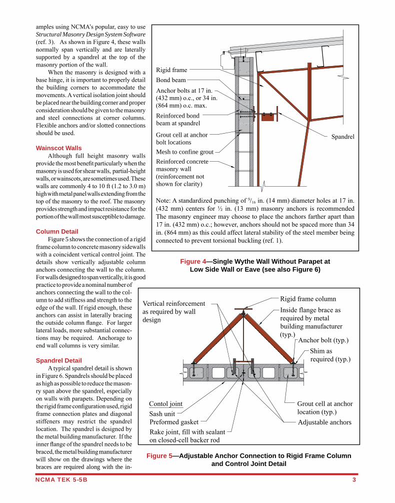
amples using NCMA’s popular, easy to use Structural Masonry Design System Software (ref. 3). As shown in Figure 4, these walls normally span vertically and are laterally supported by a spandrel at the top of the masonry portion of the wall. When the masonry is designed with a base hinge, it is important to properly detail the building corners to accommodate the movements. A vertical isolation joint should be placed near the building corner and proper consideration should be given to the masonry and steel connections at corner columns. Flexible anchors and/or slotted connections should be used.
Wainscot Walls Although full height masonry walls provide the most benefit particularly when the masonry is used for shear walls, partial-height walls, or wainscots, are sometimes used. These walls are commonly 4 to 10 ft (1.2 to 3.0 m) high with metal panel walls extending from the top of the masonry to the roof. The masonry provides strength and impact resistance for the portion of the wall most susceptible to damage.
Column Detail Figure 5 shows the connection of a rigid frame column to concrete masonry sidewalls with a coincident vertical control joint. The details show vertically adjustable column anchors connecting the wall to the column. For walls designed to span vertically, it is good practice to provide a nominal number of anchors connecting the wall to the col-umn to add stiffness and strength to the edge of the wall. If rigid enough, these anchors can assist in laterally bracing the outside column flange. For larger lateral loads, more substantial connec-tions may be required. Anchorage to end wall columns is very similar.
Spandrel Detail A typical spandrel detail is shown in Figure 6. Spandrels should be placed as high as possible to reduce the mason-ry span above the spandrel, especially on walls with parapets. Depending on the rigid frame configuration used, rigid frame connection plates and diagonal stiffeners may restrict the spandrel location. The spandrel is designed by the metal building manufacturer. If the inner flange of the spandrel needs to be braced, the metal building manufacturer will show on the drawings where the braces are required along with the in-
NCMA TEK 5-5B 3
Figure 4—Single Wythe Wall Without Parapet at Low Side Wall or Eave (see also Figure 6)
Note: A standardized punching of 9/16 in. (14 mm) diameter holes at 17 in. (432 mm) centers for ½ in. (13 mm) masonry anchors is recommended The masonry engineer may choose to place the anchors farther apart than 17 in. (432 mm) o.c.; however, anchors should not be spaced more than 34 in. (864 mm) as this could affect lateral stability of the steel member being connected to prevent torsional buckling (ref. 1).
Rigid frameBond beamAnchor bolts at 17 in.(432 mm) o.c., or 34 in.(864 mm) o.c. max.
Grout cell at anchorbolt locationsMesh to confine groutReinforced concretemasonry wall(reinforcement notshown for clarity)
Spandrel
Reinforced bondbeam at spandrel
Figure 5—Adjustable Anchor Connection to Rigid Frame Column and Control Joint Detail
Shim asrequired (typ.)
Inside flange brace asrequired by metalbuilding manufacturer(typ.)
Rigid frame column
Anchor bolt (typ.)
Grout cell at anchorlocation (typ.)Adjustable anchors
Contol jointSash unitPreformed gasketRake joint, fill with sealanton closed-cell backer rod
Vertical reinforcementas required by walldesign
REFERENCES1. Concrete Masonry Walls for Metal Building Systems, TR 149A. National Concrete Masonry Association, Metal Building Manufac-
turers Association, International Code Council, 2011.2. Serviceability Design Considerations for Steel Buildings, AISC Steel Design Guide #3. American Institute of Steel Construction, 2003.3. Structural Masonry Design System Software. National Concrete Masonry Association, Western States Clay Products Association,
The Brick Industry Association, and the International Code Council, 2010.4. Minimum Design Loads for Buildings and Other Structures, ASCE 7-05. American Society for Civil Engineers, 2005.
4 NCMA TEK 5-5B
NCMA and the companies disseminating this technical information disclaim any and all responsibility and liability for the accuracy and the application of the information contained in this publication.
NATIONAL CONCRETE MASONRY ASSOCIATION13750 Sunrise Valley Drive, Herndon, Virginia 20171
www.ncma.org
To order a complete TEK Manual or TEK Index, contact NCMA Publications (703) 713-1900
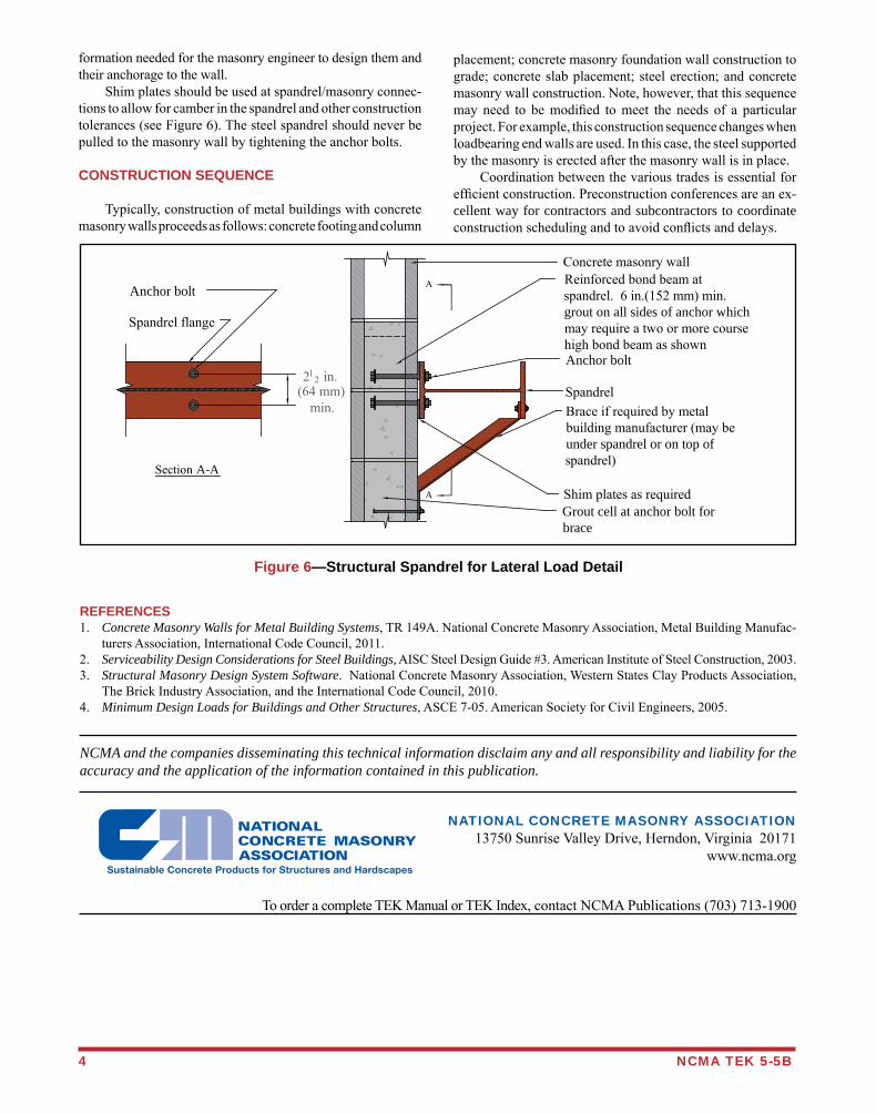
formation needed for the masonry engineer to design them and their anchorage to the wall. Shim plates should be used at spandrel/masonry connec-tions to allow for camber in the spandrel and other construction tolerances (see Figure 6). The steel spandrel should never be pulled to the masonry wall by tightening the anchor bolts.
CONSTRUCTION SEQUENCE
Typically, construction of metal buildings with concrete masonry walls proceeds as follows: concrete footing and column
Figure 6—Structural Spandrel for Lateral Load Detail
placement; concrete masonry foundation wall construction to grade; concrete slab placement; steel erection; and concrete masonry wall construction. Note, however, that this sequence may need to be modified to meet the needs of a particular project. For example, this construction sequence changes when loadbearing end walls are used. In this case, the steel supported by the masonry is erected after the masonry wall is in place. Coordination between the various trades is essential for efficient construction. Preconstruction conferences are an ex-cellent way for contractors and subcontractors to coordinate construction scheduling and to avoid conflicts and delays.
A
A Reinforced bond beam atspandrel. 6 in.(152 mm) min.grout on all sides of anchor whichmay require a two or more coursehigh bond beam as shownAnchor bolt
Spandrel
Shim plates as required
Concrete masonry wall
Anchor bolt
Spandrel flange
Section A-A
212 in.
(64 mm)min. Brace if required by metal
building manufacturer (may beunder spandrel or on top ofspandrel)
Grout cell at anchor bolt forbrace

The 10th Annual NCMA/ICPI The 10th Annual NCMA/ICPI Design Awardsof Excellence
C O M M E R C I A L
R E S I D E N T I A L
S E G M E N T A L R E T A I N I N G W A L L
P A V E R S
Call for Entries
ResidentialPaver
SRWCommercial
2011call4entries.indd 1 2/4/2011 1:02:56 PM
STEPS Step 1 – Submit your one-page entry
form and the $200 entry fee. Deadline June 15, 2011.
Step 2 – Begin compiling photographs, including a site plan and floor plan, and start writing the descriptive data.
Step 3 – NCMA will send you a binder on June 20, 2011. This binder will have additional forms in it. Fill these forms out and populate the binder with pho-tographs, a site plan and floor plan. (see page 3 for more info)
Step 4 – Mail in your completed binder to NCMA, deadline (post-marked by) August 31, 2011.
Step 5 – Judging occurs the week of September 12, 2011.
Call for Entries! Commercial, Residential, Hardscape, and Sustainability.
Submitting Project Binders
Entries for the 2011 Design Awards of Ex-cellence presented by the National Con-crete Masonry Association must be post-marked no later than June 15, 2011. That means it’s now time to plan to enter the only North American awards program that showcases design excellence and the architect’s role using concrete masonry for commercial, residential, hardscape, and sustainability applications. Winning entries serve as testimony to the creativity and ingenuity of architects, designers and landscape architects focusing on the di-versity of design excellence with concrete masonry. Entries are judged for both an Award of Excellence and an Award of Hon-or in one of four categories: commercial buildings, residential properties, hard-scape (SRW, concrete pavers, ACBs) or sustainability.
What’s in it for the winners?Winners are awarded a monetary prize and honored during an awards ceremony at the 2012 NCMA Annual Membership Meeting and industry trade show to be held in Orlan-do, Florida, March 2012. Also, all winning projects will be displayed in an awards gal-lery during the convention and trade show.
EligibilityAny architect, designer, engineer, or land-scape architect can submit entries, regard-less of project size, budget, style or type. Both established and new practitioners, from either small or large firms are encour-aged to enter and both new projects and renovation/restoration projects are eligible. Concrete masonry units—architectural block, unit concrete pavers, segmental re-
retaining walls or articulated concrete block revetment. Statements can be written onto the sheet or retyped onto a clean sheet of paper.
Concealed Identification FormThe concealed identification form (sent back in a sealed envelope) will not be shared with the judges and will be used for internal tracking of each project. The form will re-quest contact information for the architect/firm, associate architect/firm, landscape ar-chitect, owner/developer, engineers, mason-ry contractor/installer, block producer/sup-plier, and general contractor. Because every project is unique, not every project will have each of these individuals/companies.
Release FormTwo release forms will be included in the binder that is supplied. These release forms require the entrant to clear the copyrights to photos, slides, and plans for incorporation into NCMA and/or ICPI publications includ-ing and beyond the design awards program. Entrants are responsible for any royalties or copyright photography fees.
Entry forms must be postmarked no later than June 15, 2011!CALL 703.713.1900 WITH QUESTIONS.
Project Information SheetEach entrant will be required to select one item as the focus of their project. The list to choose from is below: • Design Resolution • Environmental Advancement • Preservation/Restoration • Societal Advancement • Technical Advancement• Sustainable Advancement • OtherFor more information on these categories see the “Criteria” section.
Descriptive Data SheetOn the descriptive data sheet you will be required to fully explain the design goals, design concepts, design solution, and site characteristics. The emphasis of each state-ment should focus on the use of architec-tural block, unit concrete pavers, segmental
After you submit your entry form you will receive an 8.5 x 11 inch [216 x 279 mm] binder with a few forms to fill out. These forms will include a project information sheet, a descriptive data sheet, a concealed identification form, and a release form. All material for your project submission must be contained within the binder supplied to you. A separate binder will be provided for each project submitted. Pages may not be added to the binder, but both sides of each page may be used. Submitted binders must be returned to NCMA and postmarked no later than August 31, 2011. Submissions of winning entries become the property of NCMA. If requested, every effort will be made to protect and return the submissions in good condition, but NCMA will not be held responsible for the loss or damage of any submission material.
2011call4entries.indd 2 2/4/2011 1:03:00 PM
C O M M E R C I A L • R E S I D E N T I A L • L A N D S C A P E CA
LL
F
OR
E
NT
RI
ES
:
2
01
1
Please make sure all requested items are submitted with your entry. Incomplete information may cause delays in the processing of your submission.
CriteriaEach entry in the NCMA/ICPI Design Awards of Excellence pro-gram is judged for how well the project has met the original pur-pose and objective. Scoring is weighted individually and projects are not judged in competition with each other. Document how the following themes may have been integrated into the design process for the project.• Design Resolution – Project demonstrates exemplary skill
and sensitivity in the resolution of formal, functional and tech-nical requirements.
• Environmental Advancement – Project demonstrates a commitment to environmentally sensitive design and conserva-tion.
• Preservation/Restoration – Project demonstrates skill, sen-sitivity and thoughtfulness in preservation, restoration or the alternate reuse of an existing building regardless of its original architectural intentions.
• Societal Advancement – Project demonstrates a commit-ment to social progress.
• Technical Advancement – Project explores new technolo-gies and their architectural implications.
• Sustainability – Project demonstrates and promotes sustain-ability through the use of concrete masonry products.
• Other
taining walls or articulated concrete block revetment—must be a primary construction material in order for projects to be eligible. Projects must have been designed by a licensed design professional or engi-neer at the time of completion. Design-ers may submit projects built anywhere in North America and completed within the last 5 years. Entry forms must be post-marked no later than June 15, 2011. All entries will be considered for publication in the national concrete masonry asso-ciation’s monthly architectural magazines, Concrete Masonry Designs and other pub-lications. Entrants must obtain approval to sub-mit from the owner of the project(s). It is the responsibility of the designer entering a project to inform the owners of potential site visits and the potential for media recog-nition.
Judging ProcessAn independent panel of distinguished ar-chitects and landscape architect profession-als will review all entries. Projects that credit any of the 2011 NCMA Design Awards of Excellence jury members as an architect, associate architect, landscape architect, consultant or client are ineligible. Any communication or attempt to contact a juror is inappropriate and could cause the entry to be disqualified.
Commercial and Residential Submissions Requirements Photographs must be professional in appearance and quality and shall include a minimum of one photograph of each exposed side of the building and one photograph showing the context of each exposed side of the building (may be omitted if the project’s relationship to its context is defined clearly in other prints). For a group of buildings, provide a minimum of one photograph which illustrates the complete project, including its relationship to its envi-ronment. For projects involving exterior alterations, provide a minimum of one photograph of each altered (exposed) side, and a minimum of one photograph of the same side before alteration. All projects must provide a minimum of one photograph showing the interior aspects of the building. If concrete masonry is a primary interior building material, supply images to illustrate the product’s use. The photographs submitted must total or exceed five. In addition, a small-scale site plan and floor plan, showing the project and its context, must be provided. Plans can be drawn at any scale in any medium, but the scale must be indicated graphically. All plans must be on 8.5 x 11 inch [216 x 279 mm] sheets placed in the binder’s transparent window sleeves. Please note: over-size or folded plans will be discarded without consideration.
Landscape SubmissionsPhotographs must be professional in appear-ance and quality and shall include a minimum of one photograph showing the overall environ-ment of the project and one photograph show-ing the context of each element of the project (may be omitted if the project’s relationship to its context is defined clearly in other prints). Additional photographs include a before and an under construction photograph, to illustrate the project’s significant alterations. The photo-graphs submitted must total or exceed five. In addition, a small-scale site plan, showing the project and its context, must be provided. Plans can be drawn at any scale in any medium, but the scale must be indicated graphically. All plans must be on 8.5 x 11 inch [216 x 279 mm] sheets placed in the binder’s transparent win-dow sleeves. Please note: over-size or folded plans will be discarded without consideration.
PhotographySeven or more digital photographs (300 dpi minimum on CD-ROM) or professional slides are required with the binder. In addition the site plan and floor plan(s) are also required. Each digital photograph, professional slide, site plan or floor plan must be printed in a 8 x 10 inch [203 x 254 mm] or 8.5 x 11 inch [216 x 279 mm] glossy color print and inserted into the open pockets at the back of the binder. Pages may not be added to the binder, but both sides of each page may be used. Do not submit low-resolution print-outs, color photocopies, or magazine reprints.
Entry forms must be postmarked no later than June 15, 2011!CALL 703.713.1900 WITH QUESTIONS.
2011call4entries.indd 3 2/4/2011 1:03:06 PM
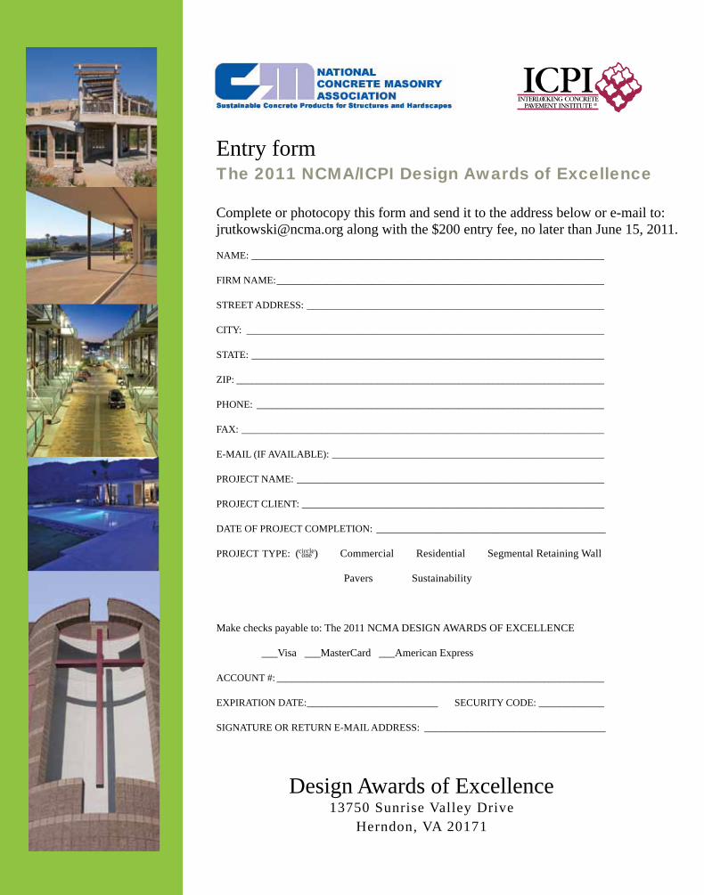
Design Awards of Excellence13750 Sunrise Valley Drive
Herndon, VA 20171
Entry formThe 2011 NCMA/ICPI Design Awards of Excellence
Complete or photocopy this form and send it to the address below or e-mail to: [email protected] along with the $200 entry fee, no later than June 15, 2011.
NAME: ______________________________________________________________________
FIRM NAME: _________________________________________________________________
STREET ADDRESS: ___________________________________________________________
CITY: _______________________________________________________________________
STATE: ______________________________________________________________________
ZIP: _________________________________________________________________________
PHONE: _____________________________________________________________________
FAX: ________________________________________________________________________
E-MAIL (IF AVAILABLE): ______________________________________________________
PROJECT NAME: _____________________________________________________________
PROJECT CLIENT: ____________________________________________________________
DATE OF PROJECT COMPLETION: ___________________________________________
PROJECT TYPE: (circle) Commercial Residential Segmental Retaining Wall
Pavers Sustainability
Make checks payable to: The 2011 NCMA DESIGN AWARDS OF EXCELLENCE
___Visa ___MasterCard ___American Express
ACCOUNT #: _________________________________________________________________
EXPIRATION DATE: __________________________ SECURITY CODE: _____________
SIGNATURE OR RETURN E-MAIL ADDRESS: __________________________________
one
2011call4entries.indd 4 2/4/2011 1:03:24 PM
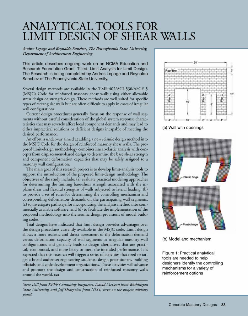
Concrete Masonry Designs 33
Andres Lepage and Reynaldo Sanchez, The Pennsylvania State University, Department of Architectural Engineering
This article describes ongoing work on an NCMA Education and Research Foundation Grant, Titled: Limit Analysis for Limit Design. The Research is being completed by Andres Lepage and Reynaldo Sanchez of The Pennsylvania State University.
Several design methods are available in the TMS 402/ACI 530/ASCE 5 (MSJC) Code for reinforced masonry shear walls using either allowable stress design or strength design. These methods are well suited for specific types of rectangular walls but are often difficult to apply in cases of irregular wall configurations.
Current design procedures generally focus on the response of wall seg-ments without careful consideration of the global system response charac-teristics that may severely affect local component demands and may lead to either impractical solutions or deficient designs incapable of meeting the desired performance.
An effort is underway aimed at adding a new seismic design method into the MSJC Code for the design of reinforced masonry shear walls. The pro-posed limit-design methodology combines linear-elastic analysis with con-cepts from displacement-based design to determine the base shear strength and component deformation capacities that may be safely assigned to a masonry wall configuration.
The main goal of this research project is to develop limit-analysis tools to support the introduction of the proposed limit-design methodology. The objectives of the study include: (a) evaluate practical modeling approaches for determining the limiting base-shear strength associated with the in-plane shear and flexural strengths of walls subjected to lateral loading; (b) to provide a set of rules for determining the controlling mechanism and corresponding deformation demands on the participating wall segments; (c) to investigate pathways for incorporating the analysis method into com-mercially available software, and (d) to facilitate the implementation of the proposed methodology into the seismic design provisions of model build-ing codes.
Trial designs have indicated that limit design provides advantages over the design procedures currently available in the MSJC code. Limit design allows a more realistic and direct assessment of the deformation demand versus deformation capacity of wall segments in irregular masonry wall configurations and generally leads to design alternatives that are practi-cal, economical, and more likely to meet the intended performance. It is expected that this research will trigger a series of activities that need to tar-get a broad audience: engineering students, design practitioners, building officials, and code development organizations. These activities will advance and promote the design and construction of reinforced masonry walls around the world. CMD
Steve Dill from KPFF Consulting Engineers, David McLean from Washington State University, and Jeff Dragovich from NIST, serve on the project advisory panel.
Figure 1: Practical analytical tools are needed to help designers identify the controlling mechanisms for a variety of reinforcement options
ANALyTICAL TOOLS FOR LIMIT DESIGN OF SHEAR WALLS
(a) Wall with openings
(b) Model and mechanism
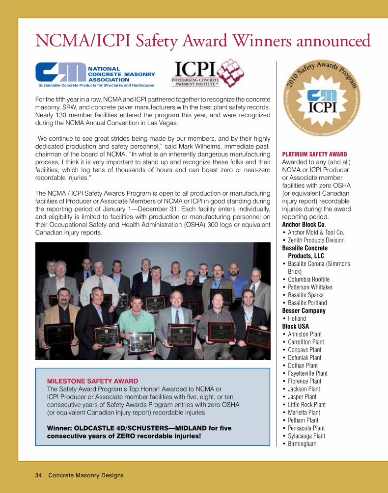
34 Concrete Masonry Designs
For the fifth year in a row, NCMA and ICPI partnered together to recognize the concrete masonry, SRW, and concrete paver manufacturers with the best plant safety records. Nearly 130 member facilities entered the program this year, and were recognized during the NCMA Annual Convention in Las Vegas.
“We continue to see great strides being made by our members, and by their highly dedicated production and safety personnel,” said Mark Wilhelms, immediate past-chairman of the board of NCMA. “In what is an inherently dangerous manufacturing process, I think it is very important to stand up and recognize these folks and their facilities, which log tens of thousands of hours and can boast zero or near-zero recordable injuries.”
The NCMA / ICPI Safety Awards Program is open to all production or manufacturing facilities of Producer or Associate Members of NCMA or ICPI in good standing during the reporting period of January 1—December 31. Each facility enters individually, and eligibility is limited to facilities with production or manufacturing personnel on their Occupational Safety and Health Administration (OSHA) 300 logs or equivalent Canadian injury reports.
NCMA/ICPI Safety Award Winners announced
PLatinuM SaFety awarDAwarded to any (and all) NCMA or ICPI Producer or Associate member facilities with zero OSHA (or equivalent Canadian injury report) recordable injuries during the award reporting period. Anchor Block Co.•AnchorMold&ToolCo.•ZenithProductsDivisionBasalite Concrete
Products, LLC•BasaliteCorona(Simmons
Brick)•ColumbiaRooftile•PattersonWhittaker•BasaliteSparks•BasalitePortlandBesser Company•HollandBlock USA•AnnistonPlant•CarrolltonPlant•ConpavePlant•DefuniakPlant•DothanPlant•FayettevillePlant•FlorencePlant•JacksonPlant•JasperPlant•LittleRockPlant•MariettaPlant•PelhamPlant•PensacolaPlant•SylacaugaPlant•Birmingham
MileStoNe SAFety AwArDThe Safety Award Program’s Top Honor! Awarded to NCMA or ICPI Producer or Associate member facilities with five, eight, or ten consecutive years of Safety Awards Program entries with zero OSHA (or equivalent Canadian injury report) recordable injuries
Winner: oLDCASTLE 4D/SCHuSTERS—MIDLAnD for five consecutive years of zERo recordable injuries!
Concrete Masonry Designs 35
•TheodorePlantCEMEX•BushnellBlockMfg.•CocoaMfg.•DavenportMfg1•DaytonaBlockMfg.•FourCornersArchMfg.•FranklinBlock/Bldg
Materials•HendersonvilleBlock•HickoryBlock•HollyHillPavers•LakelandPaverPlant•NaplesMfgPlant
4089/4090•PalmettoMfg.•RivieraBlock–1179•RivieraBlock–1182•RivieraMfg.Shop•SouthJacksonvilleMfg.•SpartanburgPavers•WatersAvenueBlockPlant•WinterParkBlock•ZephyrhillsMfg.1207•CharlotteBlock•ColfaxBlock•AndersonBlockFeatherlite Building Products•Lubbock–703•Abilene–704•Converse–706•Dallas–726Fizzano Bros. Concrete
Products Inc.•MalvernPlantFlagstone Pavers Inc.•BrooksvilleHinkle Block & Masonry Products•Allen,KYPlant•Richmond,KYPlant•Somerset,KYPlantMeade Concrete Products Inc.•NicholasvilleBlockPlantMidwest Block & Brick•Springdale,ArkansasPlant•JeffersonCityBlockPlant•KansasCityBlockPlantOldcastle–4D/Schuster’s•Berea•Midland•Bridgeport
•SheffieldOldcastle–Adams Products•AdamsProductsCastle
Hayne•AdamsProductsCowpens•AdamsProductsDunn•AdamsProducts
GreensboroVaultOldcastle–Anchor Concrete Products •ArthurWhitcomb•BetcoSupreme–Leesburg•BetcoSupreme–Crofton•BetcoSupreme–Winchester•BetcoSupreme–Gainesville•Binkley&Ober–Manheim•Binkley&Ober–
Cochranville•DomineBuilder’sSupply•LehighValleyBlock•Lyndhurst•Phillipsburg•TrenwythIndustriesOldcastle–Georgia Masonry Supply•Augusta•Cornelia•MaconOldcastle–Northfield Block Co.•RomeovilleOldcastle–Sierra Building Products•StocktonOldcastle–Superlite Block•Administration/
Transportation•CregoBlockMine•CregoBlock,SantaFe•DarlingMine•DeerValley•Gilbert•LoneButte•Needles•TriDelta•YoungBlock,SierraVista•Yuma•Phoenix•WestPhoenixOldcastle APG Texas, Inc. Jewell Concrete Products•RosenbergOldcastle Architectural Inc.•AmcorMasonryProducts
•Oldcastle—SierraBuildingProducts Fontanafacility,CategoryIII
•Oldcastle—NorthfieldBlockCo. Morrisfacility,
CategoryV•Oldcastle—SuperliteBlock
TrenwythIndustriesfacility,CategoryII
•PeerlessBlock&BrickCo. St.Albansfacility,
CategoryIV•ShouldiceDesignerStone
Ontario,Canadafacility,CategoryV
SiLver SaFety awarDRecognizesthememberfacilitywiththesecond-bestnon-zerorecordable-injuryincidencerateineachcategory.SilverSafetyAwardWinners•BesserCompany
CMC/Californiafacility,CategoryI
•Oldcastle–AdamsProducts Morrisvillefacility,
CategoryIV•OldcastleMillerMaterials
Bonnerfacility,CategoryII
Oldcastle Architectural Inc.–West, Central Pre-Mix Concrete Products Co.•PortlandFacility•KentFacility•SpokaneFacilityOldcastle Coastal •JacksonvillePlant•OrlandoPlant•ValkariaPlant
goLD SaFety awarD Recognizesthememberfacilitywiththebest,non-zerorecordable-injuryincidencerateineachcategory.GoldSafetyAwardWinners•AnchorBlockCo.
AnchorBlockSouthPlantfacility,CategoryIII
•BasaliteConcreteProducts,LLC BasaliteCarsonfacility,
CategoryIII•BasaliteConcrete
Products,LLC BasaliteDenverfacility,
CategoryIII•BasaliteConcrete
Products,LLC BasaliteDixonfacility,
CategoryV•BesserCompany
Proneq/Montrealfacility,CategoryII
•BesserCompany WorldHeadquarters
facility,CategoryV•CalstarProducts,Inc.
Racine,Wisconsinfacility,CategoryI
•Oldcastle—AnchorConcreteProducts Eastonfacility,
CategoryIII
•Ft.PiercePlant•WestPalmBeachPlant•ZephyrhillsPlantOldcastle Miller Materials•MillerMaterials–Kansas
CityOldcastle Rhino Materials•RhinoMaterialsRogers Block•Indy
categorieSDeterminedbytotalnumberofhoursworkedatafacilityareasfollows:CategoryI—0–40,000hoursCategoryII—40,001–80,000hoursCategoryIII—80,001–140,000hoursCategoryIV—140,001–200,000hoursCategoryV—200,001+hours
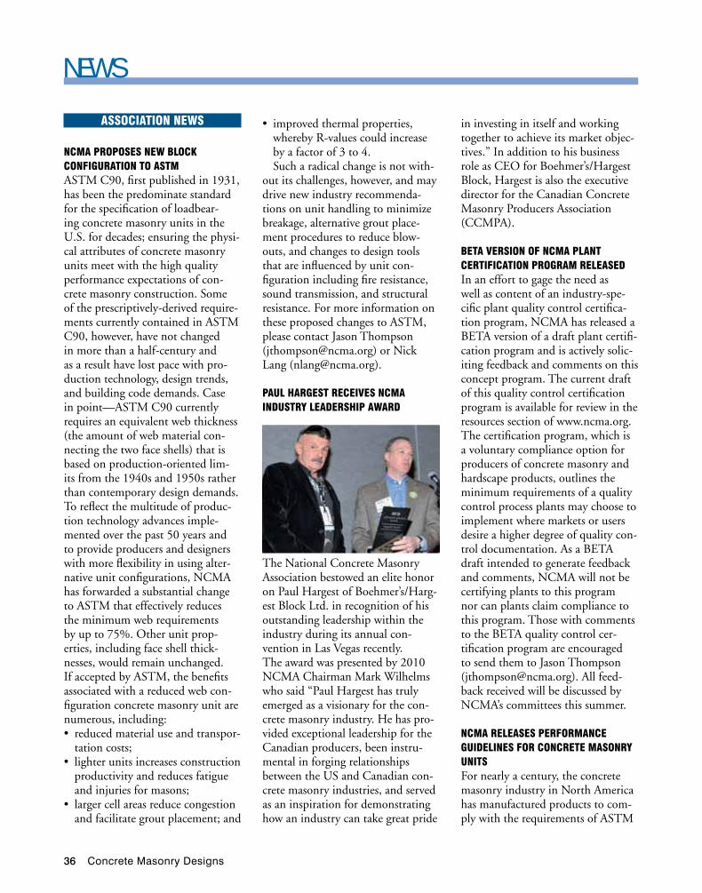
36 Concrete Masonry Designs
NEWSaSSociation newS
ncMa ProPoSeS new BLock conFiguration to aStMASTM C90, first published in 1931, has been the predominate standard for the specification of loadbear-ing concrete masonry units in the U.S. for decades; ensuring the physi-cal attributes of concrete masonry units meet with the high quality performance expectations of con-crete masonry construction. Some of the prescriptively-derived require-ments currently contained in ASTM C90, however, have not changed in more than a half-century and as a result have lost pace with pro-duction technology, design trends, and building code demands. Case in point—ASTM C90 currently requires an equivalent web thickness (the amount of web material con-necting the two face shells) that is based on production-oriented lim-its from the 1940s and 1950s rather than contemporary design demands. To reflect the multitude of produc-tion technology advances imple-mented over the past 50 years and to provide producers and designers with more flexibility in using alter-native unit configurations, NCMA has forwarded a substantial change to ASTM that effectively reduces the minimum web requirements by up to 75%. Other unit prop-erties, including face shell thick-nesses, would remain unchanged. If accepted by ASTM, the benefits associated with a reduced web con-figuration concrete masonry unit are numerous, including:• reducedmaterialuseandtranspor-
tation costs;• lighterunitsincreasesconstruction
productivity and reduces fatigue and injuries for masons;
• largercellareasreducecongestionand facilitate grout placement; and
• improvedthermalproperties,whereby R-values could increase by a factor of 3 to 4.Such a radical change is not with-
out its challenges, however, and may drive new industry recommenda-tions on unit handling to minimize breakage, alternative grout place-ment procedures to reduce blow-outs, and changes to design tools that are influenced by unit con-figuration including fire resistance, sound transmission, and structural resistance. For more information on these proposed changes to ASTM, please contact Jason Thompson ([email protected]) or Nick Lang ([email protected]).
PauL hargeSt receiveS ncMa inDuStry LeaDerShiP awarD
in investing in itself and working together to achieve its market objec-tives.” In addition to his business role as CEO for Boehmer’s/Hargest Block, Hargest is also the executive director for the Canadian Concrete Masonry Producers Association (CCMPA).
Beta verSion oF ncMa PLant certiFication PrograM reLeaSeDIn an effort to gage the need as well as content of an industry-spe-cific plant quality control certifica-tion program, NCMA has released a BETA version of a draft plant certifi-cation program and is actively solic-iting feedback and comments on this concept program. The current draft of this quality control certification program is available for review in the resources section of www.ncma.org. The certification program, which is a voluntary compliance option for producers of concrete masonry and hardscape products, outlines the minimum requirements of a quality control process plants may choose to implement where markets or users desire a higher degree of quality con-trol documentation. As a BETA draft intended to generate feedback and comments, NCMA will not be certifying plants to this program nor can plants claim compliance to this program. Those with comments to the BETA quality control cer-tification program are encouraged to send them to Jason Thompson ([email protected]). All feed-back received will be discussed by NCMA’s committees this summer.
ncMa reLeaSeS PerForMance guiDeLineS For concrete MaSonry unitSFor nearly a century, the concrete masonry industry in North America has manufactured products to com-ply with the requirements of ASTM
The National Concrete Masonry Association bestowed an elite honor on Paul Hargest of Boehmer’s/Harg-est Block Ltd. in recognition of his outstanding leadership within the industry during its annual con-vention in Las Vegas recently. The award was presented by 2010 NCMA Chairman Mark Wilhelms who said “Paul Hargest has truly emerged as a visionary for the con-crete masonry industry. He has pro-vided exceptional leadership for the Canadian producers, been instru-mental in forging relationships between the US and Canadian con-crete masonry industries, and served as an inspiration for demonstrating how an industry can take great pride
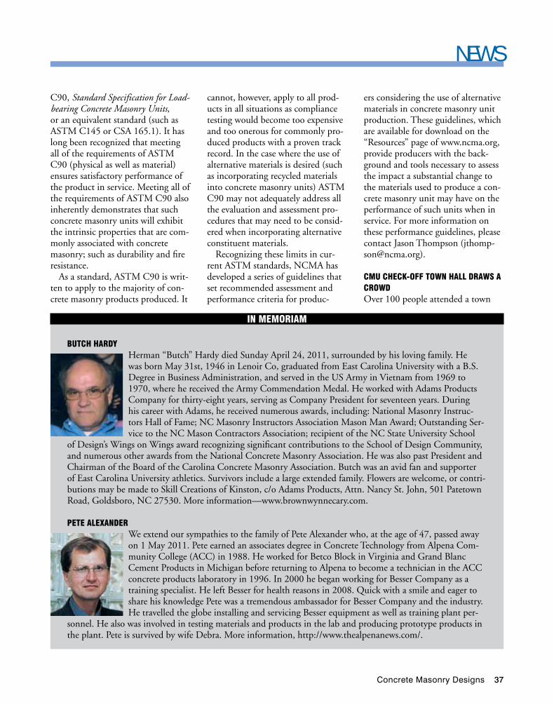
Concrete Masonry Designs 37
NEWSC90, Standard Specification for Load-bearing Concrete Masonry Units, or an equivalent standard (such as ASTM C145 or CSA 165.1). It has long been recognized that meeting all of the requirements of ASTM C90 (physical as well as material) ensures satisfactory performance of the product in service. Meeting all of the requirements of ASTM C90 also inherently demonstrates that such concrete masonry units will exhibit the intrinsic properties that are com-monly associated with concrete masonry; such as durability and fire resistance.
As a standard, ASTM C90 is writ-ten to apply to the majority of con-crete masonry products produced. It
in MeMoriaM
Butch harDyHerman “Butch” Hardy died Sunday April 24, 2011, surrounded by his loving family. He was born May 31st, 1946 in Lenoir Co, graduated from East Carolina University with a B.S. Degree in Business Administration, and served in the US Army in Vietnam from 1969 to 1970, where he received the Army Commendation Medal. He worked with Adams Products Company for thirty-eight years, serving as Company President for seventeen years. During his career with Adams, he received numerous awards, including: National Masonry Instruc-tors Hall of Fame; NC Masonry Instructors Association Mason Man Award; Outstanding Ser-vice to the NC Mason Contractors Association; recipient of the NC State University School
of Design’s Wings on Wings award recognizing significant contributions to the School of Design Community, and numerous other awards from the National Concrete Masonry Association. He was also past President and Chairman of the Board of the Carolina Concrete Masonry Association. Butch was an avid fan and supporter of East Carolina University athletics. Survivors include a large extended family. Flowers are welcome, or contri-butions may be made to Skill Creations of Kinston, c/o Adams Products, Attn. Nancy St. John, 501 Patetown Road, Goldsboro, NC 27530. More information—www.brownwynnecary.com.
Pete aLexanDerWe extend our sympathies to the family of Pete Alexander who, at the age of 47, passed away on 1 May 2011. Pete earned an associates degree in Concrete Technology from Alpena Com-munity College (ACC) in 1988. He worked for Betco Block in Virginia and Grand Blanc Cement Products in Michigan before returning to Alpena to become a technician in the ACC concrete products laboratory in 1996. In 2000 he began working for Besser Company as a training specialist. He left Besser for health reasons in 2008. Quick with a smile and eager to share his knowledge Pete was a tremendous ambassador for Besser Company and the industry. He travelled the globe installing and servicing Besser equipment as well as training plant per-
sonnel. He also was involved in testing materials and products in the lab and producing prototype products in the plant. Pete is survived by wife Debra. More information, http://www.thealpenanews.com/.
cannot, however, apply to all prod-ucts in all situations as compliance testing would become too expensive and too onerous for commonly pro-duced products with a proven track record. In the case where the use of alternative materials is desired (such as incorporating recycled materials into concrete masonry units) ASTM C90 may not adequately address all the evaluation and assessment pro-cedures that may need to be consid-ered when incorporating alternative constituent materials.
Recognizing these limits in cur-rent ASTM standards, NCMA has developed a series of guidelines that set recommended assessment and performance criteria for produc-
ers considering the use of alternative materials in concrete masonry unit production. These guidelines, which are available for download on the “Resources” page of www.ncma.org, provide producers with the back-ground and tools necessary to assess the impact a substantial change to the materials used to produce a con-crete masonry unit may have on the performance of such units when in service. For more information on these performance guidelines, please contact Jason Thompson ([email protected]).
cMu check-oFF town haLL DrawS a crowDOver 100 people attended a town
38 Concrete Masonry Designs
NEWShall meeting held in conjunction with ICON Expo and the CON-EXPO / CON-AGG shows in Las Vegas to find out more about how a check-off program could help expand concrete masonry mar-kets. Major Ogilvie, a representa-tive from BlockUSA that is chairing the industry effort, hosted the event. Participants were provided with background that led the industry to undertake such an initiative, exam-ples of successes from industries have implemented similar programs, and a preview of how a concrete masonry check-off program is envisioned to operate. The session concluded with a lively questions and answers ses-sion. The industry will continue its communications and outreach efforts regarding the program while pursuing authorization for imple-mentation. Refer to the dedicated website for additional information: www.cmucheckoff.com
thoMPSon naMeD ncMa vice PreSiDent oF engineering
The NCMA Board of Direc-tors approved Jason J. Thompson as its new Vice President of Engineering.
Thompson, a structural engineer that has been with NCMA for 14 years, received the appointment during NCMA’s Annual Conven-tion last week in Las Vegas. He has served in many leadership capaci-ties on behalf of the association and the masonry industry including the chairman of the Masonry Alli-ance for Codes and Standards and secretary of the Masonry Standards Joint Committee. He has also been recognized through several awards including receiving ASTM’s Alan H. yorkdale Award for the best techni-
cal paper regarding masonry written in the English language on three sep-arate occasions. He currently man-ages NCMA’s technical and research activities.
aSce honorS DenniS graBer with LiFe MeMBer awarD
The Ameri-can Society of Civil Engi-neers (ASCE) bestowed the honor on Den-nis Graber, NCMA Direc-
tor of Technical Publications, at the meeting of the National Capitol Sec-tion meeting on April 19. Graber has maintained his membership in ASCE since graduating from col-lege and has served on several ASCE national committees throughout his professional career. The presentation was made by Kathy Caldwell, Presi-dent of ASCE National.
ncMa weLcoMeS new ProDucer MeMBer a-1 BLock corPorationPlease join us in welcoming our newest member aboard! A-1 Block Corporation, 1617 Division Ave. S, Orlando, Florida 32805, 407-422-3768, www.a1block.com. Sponsors: Bill Oberfield, Oberfield’s Inc., and Columbia Machine.
inDuStry newS
4th annuaL hna harDScaPe Project awarDS now oPen! The Hardscape North America Hardscape Project Awards is now accepting projects to be considered for this year’s contest. The awards recognize outstanding hardscape projects by contractors in com-mercial/industrial, residential and transportation/municipal street applications. These projects may
include but are not limited to walk-ways, patios, driveways, plazas, park-ing lots, roadways, etc. For more information, log on to www.hard-scapeNA.com/HNAawards .
ncMa MeetingS anD icon exPo newS
Save the Date—2011 ncMa MiDyear & icPi SuMMer MeetingThe National Concrete Masonry Association (NCMA) and the Inter-locking Concrete Pavement Insti-tute (ICPI) will join together to conduct their 2011 summer mid-year meetings, August 24–28 at the Hyatt Regency Vancouver Hotel. Committee meetings will be coor-dinated so that members are able to attend meetings of both organiza-tions. Additional events will include the NCMA Business Luncheon and PAC Reception and a combined joint NCMA/ICPI Member Net-working reception and NCMA/ICPI Golf Tournament. Important travel informaiton—you must have a valid passport or alternate approved travel document to enter or depart the United States. This process can take time, so if you do not have a pass-port or alternate approved travel document, please apply now so that you are prepared to travel at the time of the meeting. For more infor-mation on travelling between the United States and Canada, please visit the following website http://canada/usembassy.gov.
the PrecaSt Show 2012 Featuring icon exPo heaDS For orLanDo!It is never too early to plan your par-ticipation and attendance, and in 2012 this show brings back together the major industry components to create the ONLy show in North America and the largest annual show in the world geared exclusively to
NEWS
Concrete Masonry Designs 39
the manufactured concrete prod-ucts industry! In 2012, the Pre-cast Show will include PRECAST, PIPE, MASONRy AND HARD-SCAPES, and is not to be missed. The show will include exhibition, education and networking events, coinciding with association meet-
ings and annual conventions. The host hotel is Shingle Creek Resort. Previous MCPX and ICON EXPO exhibitors have been contacted for priority booth placement, and open sales have already begun, with the major exhibit sales campaign begin-ning after Memorial Day. The floor
is already 80% sold and is expected to sell out, however, priority ranked exhibitors still have time to secure ideal location in one of the three dis-tinct pavilions, visit www.theprecast-show.org or contact Brenda Ibitz at [email protected].
FounDation newS
ncMa FounDation awarDS over $98,000 in new grantS The NCMA Education and Research Foundation at its meetings last week in Las Vegas, NV approved eight new grants and student design competitions to various universities and other institutions, totaling over $98,000. Those programs funded include the following:
Grants:• MasonContractorsAssociation
of America for MILCON Ph. II—$20,000
• TheMasonrySocietyforSustain-ability e-Newsletter—$1,200
• ClemsonUniversityforStu-dent Verification of Structural Masonry Design Software Version 6—$8,000
• Ensoltec,Inc.forDirectDesignSoftware—$30,000
• BrighamYoungUniversityforHigh Replacement of Portland Cement in Masonry—$19,250
• UniversityofWyomingforPlas-tic Shrinkage Research Phase II—$6,100
Student Design Competitions:• FloridaAtlanticUniver-
sity—$7600• BallStateUniversity—$6,000
New grant submissions will be considered at NCMA’s Mid-year Meeting in Vancouver, BC in August. The submittal deadline the next round of grant applications is July 1, 2011. Forms and more infor-mation on submitting a grant appli-
cation are posted on the NCMA Foundation web site at www.ncma.org/foundation or you can contact NCMA Director of Technical Publi-cations Dennis Graber at [email protected].
MiLcon reSearch Project to receive FunDing FroM ncMa FounDation MCAA and NCMA have partnered for a research project to address questions raised in an April 2010 report published by the General Accountability Office (GAO) titled DOD Needs to Determine and Use the Most Economical Build-ing Materials and Methods When Acquiring New Permanent Facili-ties (GAO-10-436). The GAO report was a result of industry pres-sure stemming from the Depart-ment of Defense decision to replace durable masonry construction with other systems and materials that have a perceived lower cost of ini-tial construction. When taking long-term maintenance and operating costs into consideration, however, the short-term goal of reducing the initial cost of construction may be unjustified. In their report, the GAO concluded:
…it is not clear that the Army’s expanded use of wood materials and modular building methods will achieve the Army’s intended pur-pose of reduced facility costs over the long term. The Navy and the Air Force generally disagreed with the
Army’s view and believed that the use of wood materials and modular construction will result in facilities with shorter service lives and higher life-cycle costs. However, none of the services had the analyses to sup-port its views.
As a result of this study, the GAO concluded with the following recom-mendation:
GAO recommends that the Department of Defense (DOD) determine the merits and long-term costs from the use of alterna-tive building materials and methods and subsequently revise its military construction guidance, as deemed appropriate. DOD generally agreed with the recommendations.
The MILCON project will study multiple construction types and methods including, wood, concrete, steel, masonry, and wood modu-lar construction to document tak-ing into consideration initial cost of construction, timeline, sustainability, antiterrorism design, and life-cycle costs. The study slated to be com-pleted by early Fall 2011 is expected to support the industry position that masonry is the preferred mate-rial and method of construction in addressing the questions raised by the GAO report. For more informa-tion on this project contact NCMA Vice President of Engineering Jason Thompson [email protected] or NCMA Director of Technical Publi-cations Dennis Graber at [email protected]. CMD
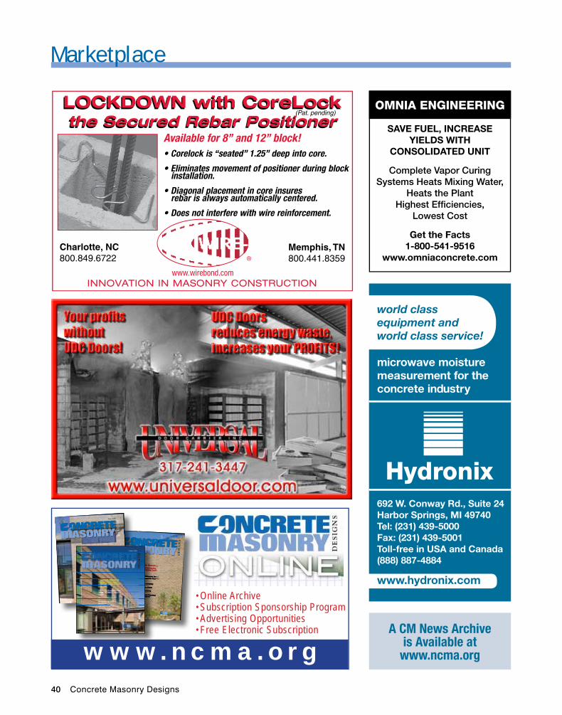
40 Concrete Masonry Designs
Marketplace
www.hydronix.com
microwave moisture measurement for the concrete industry
Hydronix692 W. Conway Rd., Suite 24Harbor Springs, MI 49740Tel: (231) 439-5000Fax: (231) 439-5001Toll-free in USA and Canada(888) 887-4884
world class equipment and world class service!
OMNIA ENGINEERING
SAVE FUEL, INCREASE YIELDS WITH
CONSOLIDATED UNIT
Complete Vapor Curing Systems Heats Mixing Water,
Heats the Plant Highest Efficiencies,
Lowest Cost
Get the Facts 1-800-541-9516
www.omniaconcrete.com
A CM News Archive is Available at
www.ncma.org
(Pat. pending)LOCKDOWN with CoreLockthe Secured Rebar Positioner
Available for 8” and 12” block! • Corelock is “seated” 1.25” deep into core.
• Eliminates movement of positioner during block installation.
• Diagonal placement in core insures rebar is always automatically centered.
• Does not interfere with wire reinforcement.
®
www.wirebond.com
Memphis, TN800.441.8359
Charlotte, NC800.849.6722
INNOVATION IN MASONRY CONSTRUCTION
LOCKDOWN with CoreLockthe Secured Rebar Positioner
A PublicAtion of the
www.ncmA.oRg
De
sig
ns
August 2009
Concrete Masonry Builds Character in an Arizona Infill ProjectTEK 17-1C Allowable Stress Design of Concrete Masonry Lintels
The 6 Ds of Durability
Expanding an Urban Residence from the Ground Up
AIA Continuing Education Learning Program
De
sig
ns
ASONRY
asonryA PublicAtion of the
www.ncmA.oRg
De
sig
ns
August 2009
Concrete Masonry Builds Character in an Arizona Infill Project
TEK 17-1C Allowable Stress
Design of Concrete Masonry
Lintels
The 6 Ds of Durability
Expanding an Urban
Residence from the Ground Up
AIA Continuing Education
Learning Program
ASONRY
ASONRY
Concrete Masonry Builds Character in an Arizona Infill ProjectTEK 17-1C Allowable Stress Design of Concrete Masonry LintelsDesign of Concrete Masonry LintelsDesign of Concrete Masonry
The 6 Ds of Durability
Expanding an Urban Residence from the Ground Up
AIA Continuing Education Learning Program
ASONRYConcrete Masonry Builds Character in an Arizona Infill Project
TEK 17-1C Allowable Stress Design of Concrete Masonry
ASONRY
A PublicAtion of the
www.ncmA.oRg
Concrete Masonry Builds Character Concrete Masonry Builds Character Concrete Masonry
in an Arizona Infill Project
TEK 17-1C Allowable Stress
Design of Concrete Masonry
Lintels
The 6 Ds of Durability
Expanding an Urban
Residence Expanding an Urban
Residence Expanding an Urban
from the Ground Up
AIA Continuing Education
Learning Program
www.ncma.or g
Online Archive•Subscription Sponsorship Program•Advertising Opportunities•Free Electronic Subscription •
Concrete Masonry Designs 41
Marketplace
We Always Think About Customer Satisfaction!
Flatness GuaranteedHigh Tensile Steel
Maintenance Solutions
Before Using the Dust Cleaner
After Using theDust Cleaner
*Dust Collector Included with Board Cleaner Steel Racks
Before Using the Dust Cleaner
*Dust Collector Included with Board Cleaner
Innovative
Light Weight
Steel Pallets
Now Available!
NEW
535 N. Wolf Rd. Wheeling, IL 60090T 847 . 465 . 0925 F 847 . 465 . 0989For sales: [email protected]
Steel Pallets Steel Racks Steel Wheel Discs Board Cleaners
Call today for your free quote! (847) 465.0925 / (847) 224.0264
Have You Taken Advantage of all the resources available
on the NCMA web site?
•e-TEK•Bookstore•DesignResources•TEKTechnical
Information•ResearchReports•MetricDesign
Guidelines•EnergyCodeOptions
forCMU•Sustainability
Information•TechnicalServices•TechnicalPublications
Database•FireandAcoustics•DesignAwards
Program•MarketingResources•ArticlesforPrintand
Radio•CameraReadyArtwork•Fire Safety Materials•MoldMaterials•PrintAds•SafetyResources•eSafetyLineSoftware•Opportunities/Leads•HelpfulLinks•FireSafety
Associations•MoldResources•Workforce
Development
VISIT TODAYwww.ncma.org
THE ORIGINAlwww.careercrete.com
Block | Paver | Pipe | Precast | Ready Mix
CONCRETE INDUSTRY ASSOCIATES EMPlOYMENT AGENCY
PO Box 954 Grand Haven, MI 49417Tel: 616-842-0227E-mail: [email protected]
member of
icon exPo Booth # S-20939
42 Concrete Masonry Designs
Marketplace
• OPERATIONS AND PLANT MANAGERS • SHIFT SUPERVISORS • MACHINE OPERATORS
• MAINTENANCE • SALES
Michael S. Stauffer • 610-351-8070 • Cell: 610-417-5503 [email protected]
www.UnitedEmploymentGroup.com
BLOCK AND PAVER INDUSTRY SPECIALISTNATIONWIDE SEARCH & RECRUITMENT
For advertising information, call
NCMA 703-713-1900.
AlABAMA PAllETS
“Your Dependable and Experienced Steel Pallet and Rack Source for the Concrete
Block and Paver Industry”
Mike CrancerPhone: (636) 861-7300
Toll Free: (888) 530-7337Fax: (636) 861-7335
E-mail: [email protected]
Contact us for a FREE Brochure!
Buying/Selling Used EquipmentBlock Machines, Block Plants, Batch Plants, Crushers, Forklifts,
Front End Automation, Lintel Machines, Mixers, Paver Plants, Precast, Cubers, Racks/Pallets, Roof Tile Machines, Trucks
6069 Oakbrook Parkway, Norcross, GA 30093Phone: (800) 247-2819 or (770) 840-7060
Fax: (770) 840-7069e-mail: [email protected]
www.iwigroup.com
member of
WWW.GEOGRID.COM
• HIGHEST QUALITY GEOGRIDS
• BEST CUSTOMER SERVICE
• COMPETITIVE PRICES
Marketplace Ads are Affordable and Effective. Let NCMA design
one for YOU.
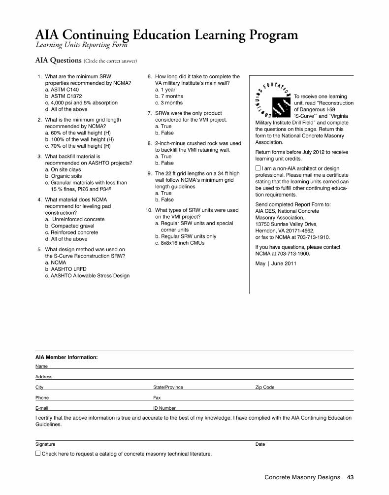
Concrete Masonry Designs 43
To receive one learning unit, read “Reconstruction of Dangerous I-59 ‘S-Curve’” and “Virginia
Military Institute Drill Field” and complete the questions on this page. Return this form to the National Concrete Masonry Association.
Return forms before July 2012 to receive learning unit credits.
I am a non-AIA architect or design professional. Please mail me a certificate stating that the learning units earned can be used to fulfill other continuing educa-tion requirements.
Send completed Report Form to: AIA CES, National Concrete Masonry Association, 13750 Sunrise Valley Drive, Herndon, VA 20171-4662, or fax to NCMA at 703-713-1910.
If you have questions, please contact NCMA at 703-713-1900.
May | June 2011
AiA Member information:
Name
Address
City State/Province Zip Code
Phone Fax
E-mail ID Number
I certify that the above information is true and accurate to the best of my knowledge. I have complied with the AIA Continuing Education Guidelines.
Signature Date
Check here to request a catalog of concrete masonry technical literature.
aIa Continuing education Learning Program Learning Units Reporting Form
1. What are the minimum SRW properties recommended by NCMA?a. ASTM C140b. ASTM C1372c. 4,000 psi and 5% absorptiond. All of the above
2. What is the minimum grid length recommended by NCMA?a. 60% of the wall height (H)b. 100% of the wall height (H)c. 70% of the wall height (H)
3. What backfill material is recommended on AASHTO projects?a. On site claysb. Organic soilsc. Granular materials with less than
15 % fines, PI£6 and f³34º
4. What material does NCMA recommend for leveling pad construction?a. Unreinforced concreteb. Compacted gravel c. Reinforced concreted. All of the above
5. What design method was used on the S-Curve Reconstruction SRW?a. NCMAb. AASHTO LRFDc. AASHTO Allowable Stress Design
6. How long did it take to complete the VA military Institute’s main wall?a. 1 yearb. 7 monthsc. 3 months
7. SRWs were the only product considered for the VMI project.a. Trueb. False
8. 2-inch-minus crushed rock was used to backfill the VMI retaining wall.a. Trueb. False
9. The 22 ft grid lengths on a 34 ft high wall follow NCMA’s minimum grid length guidelinesa. Trueb. False
10. What types of SRW units were used on the VMI project?a. Regular SRW units and special
corner unitsb. Regular SRW units onlyc. 8x8x16 inch CMUs
aIa Questions (Circle the correct answer)
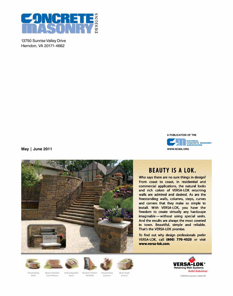
May | June 2011
13750 Sunrise Valley DriveHerndon, VA 20171-4662
A PubliCAtioN oF tHe
www.NCMA.org
De
sig
ns
ASONRY
© 2008 Kiltie Corporation • Oakdale, MN
Mosaic Random Face Patterns
Freestanding Walls
Fully Integrated Stairs
Random-Pattern Tall Walls
Freestanding Columns
Multi-Angle Corners


![C H IN ESE M ASONRY. FOR HIGH ?nyshistoricnewspapers.org/lccn/sn94057918/1886-09-03/ed... · 2014-06-03 · September 3,1886.] Tiie YorxnsTowx N e w s. C H IN ESE M ASONRY. LA B 0](https://img.pdfslide.us/doc/110x75/5cfc74ed88c993de0d8bde65/c-h-in-ese-m-asonry-for-high-n-2014-06-03-september-31886-tiie-yorxnstowx.jpg)