Embed Size (px)
Citation preview

www.illustratingshadows.com CASE STUDY: a vertical decliner in ceramic
Page 1 of 15 This file may be copied and printed and distributed free of change provided this notice is retained. Simon Wheaton-Smith www.illustratingshadows.com
VERTICAL DECLINING DIALS First: measure north with an astro compass, 3 to 5 readings averaged, hence the wall declination and/or measure north with a magnetic compass, three readings, one east, west, and south of the spote, readings being about 20 feet away and/or measure wall declination with the measured versus actual azimuth, do about five readings, reject the two extremes Then: design the hour lines and style distance Then: create the calendar curves, at a minimum the winter solstice and the equinox line Then: derive the sunset time for the winter solstice and using 6pm for the equinox adjust both for longitude difference with the legal meridian derive the winter solstice point for 1, 2, 3, ... hours before sunset ditto for the equinox then draw the Italian lines Then: make the dial plate Then: might as well do the same for the north facing wall also Useful references: ILLUSTRATING SHADOWS ch 4 Determining true north since we need the polar axis ch 12 A vertical decliner, predominantly south facing ch 14 The great decliner, predominantly east or west facing ch 16 Declination or Calendar lines revisited Ap 5 Tables for the vertical decliners, east/west and south decliners Ap 6 Sunrise and set for some locations. Italian/Babylonian hour data. ILLUSTRATING MORE SHADOWS
ch 3 where is north ch 9 the declining dials The entire book has numerous examples worked with differing methods for vertical decliners, geometric, trigonometric, DeltaCAD, Excel, etc
CASE STUDIES and dialling aids (on the web site) s44w-s46e-cube-dial-design.pdf cube-dial-design-HeyFarm.pdf CaseStudy-S5W-v-clay.pdf Excel: illustrating-shadows.xls (previously reference-spreadsheets.xls) sheet-a5.1-vertical-south-decliners.xls DeltaCAD: sws-v-dec-dial.bas, sws-v-dec-facing-pole.bas sws-v-dial.bas JustBASIC: sws-bas-h-vdec-dial.bas VRML: n-and-s-of-v-dec-s5w-n5e.wrl (use Cortona plug-in), click the link, ignore the Adobe warning, click FIT, then click STUDY). MAKE SURE you download: http://www.illustratingshadows.com/n-and-s-of-v-dec-s5w-n5e.wrl
May 19, 2007

www.illustratingshadows.com CASE STUDY: a vertical decliner in ceramic
Page 2 of 15 This file may be copied and printed and distributed free of change provided this notice is retained. Simon Wheaton-Smith www.illustratingshadows.com
A SOUTH DECLINING WEST VERTICAL DIAL A predominantly south facing wall was in need of a vertical dial so that the passers by, mostly college students, could determine the time and thus hurry on to their lectures. The dial location was 32.75° north, and west 108.2° with a legal time meridian of 105°. The first objective was to determine the wall's declination, and three methods were selected. Astro-compass determination of wall declination The process is simple, the sun's hour angle assuming 15° per hour is calculated for the time of observation, a few minutes from now. Then the longitude correction plus the EOT set to degrees (EOT divided by four) are subtracted from that sun's hour angle. This is the opposite to the correction made when reading a sundial. The astro-compass is set, and placed on a plane such as a wooden plank. The astro-compass is rotated until the shadow is centered. The angle of the astro-compass axis is projected onto the wood, I use a projection of the leveling mechanism. The angle that the projected line makes with the wooden planks edge paralleling the wall determines the wall declination. In practice the illustrating-shadows.xls spreadsheet or the table A2.2a in the appendices simplifies this process. For the wall in question several readings showed a wall declination of S 5°W. A page at the back of this case study expands on the process.
Magnetic compass determination of wall declination The magnetic compass is placed on a plane such as a wooden plank, and was set to project a perpendicular line to the wall being measured. The compass needle showed between 355 degrees. The dial location had a magnetic declination (variation to navigators and pilots) of 10.2 degrees easterly. Thus the true bearing of the wall's perpendicular was 365 or 005 degrees. The reciprocal of 005° is 185°. Thus the wall declines S 5° W. This agreed with the astro-compass method.

www.illustratingshadows.com CASE STUDY: a vertical decliner in ceramic
Page 3 of 15 This file may be copied and printed and distributed free of change provided this notice is retained. Simon Wheaton-Smith www.illustratingshadows.com
Measured versus calculated azimuth method
The illustrating-shadows.xls spreadsheet allows a time in hours and minutes to be entered together with a nodus shadow x and y coordinates. In actuality the "x" coordinate is used to derive the azimuth. This method is expanded on in two pages at the back of this case study. This method showed a little under 5°.
Points to consider when determining wall declination A page at the end of this case study provides some insights on matters that can cause confusion. In essence, it is a good idea to make calculations before hand, and develop a script, and follow it. It is possible to confuse the sense of a wall declination if care is not taken to ensure magnetic declination is understood. The final decision was made to assume a South 5° West wall declination. Then two processes were used. One to determine the hour line angles, and thus the SD and SH, style distance and style height. The illustrating-shadows.xls spreadsheet does this, so do various programs on this book's web site. Programs on the web site cover DeltaCAD, C, FORTRAN, Pascal, Visual Basic, Basic, and java. And all of them have free compilers available which the website directs you to, except for DeltaCAD. In this case the sws-v-dec-dial.bas DeltaCAD macro was used.

www.illustratingshadows.com CASE STUDY: a vertical decliner in ceramic
Page 4 of 15 This file may be copied and printed and distributed free of change provided this notice is retained. Simon Wheaton-Smith www.illustratingshadows.com
To the right is shown the DeltaCAD depiction using the vertical decliner macro, The next step was to make a mockup dial, and affix it to the final wall, and test it.
The dial tested correctly, this test is a wise idea because it is somewhat disheartening to build a dial and find out that there was an "opportunity for improvement" after hours of dial plate construction.
Next, the DeltaCAD macro sws-calendar-curves.bas was used to draw the calendar curves. This program is nothing more than the horizontal dial with calendar curves, except it is tailored just to calendar information. The "latitude" is replaced with the style height (SH). There is no longitude correction. And the style height is taken from the first dial plate. The drawing has some hour lines which are meaningless, except they can be used with their intersection points on calendar curves, to transcribe those points to the final dial. And, the "noon" line of those calendar lines is aligned with the style distance (SD) or the regular dial plate.

www.illustratingshadows.com CASE STUDY: a vertical decliner in ceramic
Page 5 of 15 This file may be copied and printed and distributed free of change provided this notice is retained. Simon Wheaton-Smith www.illustratingshadows.com
Then, the real dial plate is transcribed to a final sheet of paper, and the calendar depiction is rotated so that its noon line matches the style distance of the first plate, and the information transposed.
SD on the actual dial plate
"noon" on the calendar curve depiction.
The hour lines on the calendar plate are meaningless as far as hour lines go. However, they are very useful in transcribing as well as rescaling the calendar curves. When transcribing those curves, remember that the "hour lines" on the calendar depiction do not match hour lines on the actual dial plate. The main thrust of this web site and these books is educational, the focus is on showing the "how" of dial design. If you desire a more turnkey operation, consider using SHADOWS which while not affiliated with this web site and series of books, provides an excellent depiction of final dial plates.
gnomon to scale for the calendar lines

www.illustratingshadows.com CASE STUDY: a vertical decliner in ceramic
Page 6 of 15 This file may be copied and printed and distributed free of change provided this notice is retained. Simon Wheaton-Smith www.illustratingshadows.com
The end result is a paper sheet the size of the final dial plate. This will be used to make impressions upon the soft clay. This dial plate will fit in a surround of miscellaneous pieces of clay that were fired but for one reason or another never used.
A slab of clay was cut from supplies and rolled. This dial plate area measured 11 inches vertically, and 15 inches horizontally.
The upper half of the dial plate has a diagonal cut along the style distance. The lower half has the diagonal cut along the noon line. Then some extra pieces were cut so they would look nice while fit with kiln firing dimensions. The equinox line, hour lines, and Italian lines will be, along with their lettering, made with a slip or an under-glaze.
For aesthetics, a strip and a crown would be added.
www.illustratingshadows.com CASE STUDY: a vertical decliner in ceramic
Page 7 of 15 This file may be copied and printed and distributed free of change provided this notice is retained. Simon Wheaton-Smith www.illustratingshadows.com
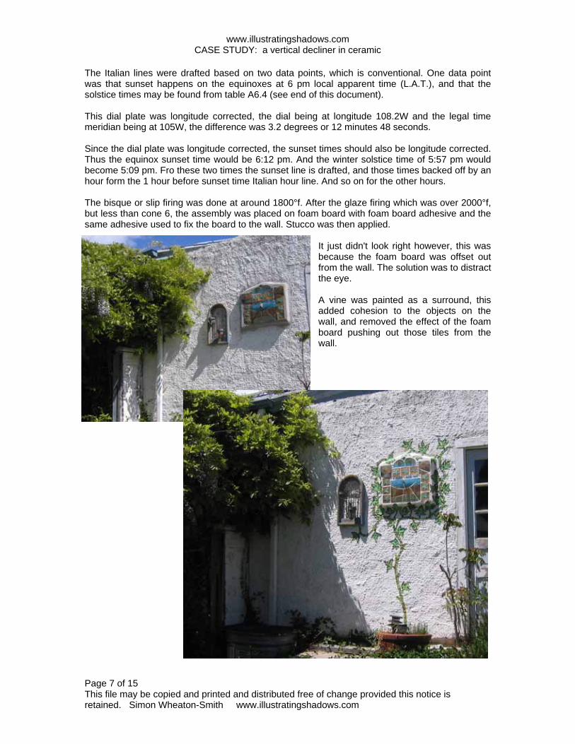
The Italian lines were drafted based on two data points, which is conventional. One data point was that sunset happens on the equinoxes at 6 pm local apparent time (L.A.T.), and that the solstice times may be found from table A6.4 (see end of this document). This dial plate was longitude corrected, the dial being at longitude 108.2W and the legal time meridian being at 105W, the difference was 3.2 degrees or 12 minutes 48 seconds. Since the dial plate was longitude corrected, the sunset times should also be longitude corrected. Thus the equinox sunset time would be 6:12 pm. And the winter solstice time of 5:57 pm would become 5:09 pm. Fro these two times the sunset line is drafted, and those times backed off by an hour form the 1 hour before sunset time Italian hour line. And so on for the other hours. The bisque or slip firing was done at around 1800°f. After the glaze firing which was over 2000°f, but less than cone 6, the assembly was placed on foam board with foam board adhesive and the same adhesive used to fix the board to the wall. Stucco was then applied.
It just didn't look right however, this was because the foam board was offset out from the wall. The solution was to distract the eye. A vine was painted as a surround, this added cohesion to the objects on the wall, and removed the effect of the foam board pushing out those tiles from the wall.

www.illustratingshadows.com CASE STUDY: a vertical decliner in ceramic
Page 8 of 15 This file may be copied and printed and distributed free of change provided this notice is retained. Simon Wheaton-Smith www.illustratingshadows.com
THE SAME VERTICAL DECLINER BUT NORTH FACING – S 175°E or N5°E The north side of the same building can be used for a vertical dial, useful for the summer months. In the northern hemisphere the EOT for a pure north dial would range between +/– 7 minutes. The relationship of the S 5° W and N 5° E vertical decliners is shown below. VERTICAL DECLINERS Gnomon points up, hour lines radiate from bottom POLE FACING N 5 E gnomon hours clockwise in northern hemisphere northern hemisphere note that the final VERTICAL DECLINERS hours are counter SD is of an opposite SOUTH FACING clockwise sign S 5 W gnomon Gnomon points down, hour lines radiate from top A variation of the vertical declining DeltaCAD program was used, sws-v-dec-facing-pole.bas, this dial declines S 175° E or N 5° E, the latitude and longitude being the same.
The program modifications removed animation, modified the prompts and defaults, added showing hour line angles from horizontal, rotated the dial plate 180 degrees to force the gnomon to the top, the sign of SD was changed, and a few other trivia. This modified program simplifies dial plate orientation and construction, however, the normal vertical decliner methods can be used with minor human manipulation, as was seen in chapter 9, "CASE STUDY ~ A CUBE DIAL ON A COLUMN ~ mostly SW/SE points".

www.illustratingshadows.com CASE STUDY: a vertical decliner in ceramic
Page 9 of 15 This file may be copied and printed and distributed free of change provided this notice is retained. Simon Wheaton-Smith www.illustratingshadows.com
The angles of the hour lines to the horizontal were measured using DeltaCAD's measurement tool showing how they match the displayed hour line angle data. Those angles also match other available software popular with diallists, such as SHADOWS and ZW2000.
To the left is shown a CAD vertical dial with the equator facing plate on the lower half, the pole facing plate on the upper. This shows how the SD is deflected to the right (for this wall's declination) for both plates when viewed looking at the plate from the sun's side and how noon or midnight is deflected to the left (for this longitude) for both plates when viewed looking at the plate from the sun's side. The plate was tested in the morning and afternoon hours and was correct. The print out was placed on a slab of clay, and lines traced into the clay with a blunt pencil. The plate was fired as before.
The earliest and latest hours would be sunrise and set, table A6.4 (books 1 or 2). The latest morning and earliest afternoon hours would be when the azimuth at the summer solstice crosses the east west line, tables A4.2 book 1. For latitude 32 that would be 0500 to 0900 mst and 1500 to 1900 mst. Although daylight savings time might be better choice, the author has a bias towards standard time since was shown in 2007 in the USA, daylight savings time is a variable at the whim of the government and serves little obvious purpose. Wall declination and shading of course affect the useful hours displayed.
57° 57°

www.illustratingshadows.com CASE STUDY: a vertical decliner in ceramic
Page 10 of 15 This file may be copied and printed and distributed free of change provided this notice is retained. Simon Wheaton-Smith www.illustratingshadows.com
This uses the same theory as backing off or advancing the clock time for a sighting, but instead of adjusting the time of the sighting, the hour angle is adjusted by advancing it or retarding it based on a degree equivalent (as opposed to a time equivalent) of the sum of the longitude and equation of time (EOT) corrections. Also, standard time is used, rather than considering daylight saving time in mid-calculation. EOT from table A2.1 mm.ss First, get the equation of time for the day, the EOT is in table A2.1 in the appendices. For March 27, this is +5.37 (mm.ss), meaning that this is added to a sundial reading. Convert this to degrees, using 4 minutes per degree. This is 5m 37s, or 5.6 minutes and that becomes 1.4 degrees, positive when divided by four. Next, derive the longitude correction for the dial's location, which is the location's longitude minus the legal time zone's meridian longitude. For a dial at location W108.2 and a legal time zone meridian of W105, the number is 3.2 degrees. A positive number. Next, add the EOT in degrees and longitude correction in degrees giving 3.2 plus 1.4, in other words 4.6 degrees positive. Next, look at your accurate watch and pick the nearest time whose minutes is a multiple of 4. In this case it was 12:43 daylight savings, thus this is 11:43 standard time. The 11:48 daylight saving time simplifies calculations. This was 12 minutes before noon, or at 4 minutes per degree, this was 357° (3° before noon). Finally, the sun's hour angle (in this case 357° or 3° before noon) is adjusted by the total EOT and longitude correction. Since the time was before noon, the 3 degrees is backed off by (has subtracted from it) the 4.6 degrees. This results in 7. 6 degrees as the correct solar hour angle for 12:48. Note: 7.6° is less than 3° when you consider them to be 352.4° and 357° respectively. The astro-compass having been set, it is used as described on the previous page. Table A2.2a and the master spreadsheet illustrating-shadows.xls make this process very simple. Longitude
– Legal Meridian
= Location correction
108.2 w – 105 w = + 3.2° EOT for the day mm.ss
EOT for the day mm.mm
EOT/4 Total correction
+ 5m 37s + 5.6 = + 1.4° + 4.6°
Mar Apr May 1 12.31 4.06 -2.48
2 12.19 3.49 -2.56
3 12.07 3.31 -3.02
25 6.13 -1.54 -3.10 26 5.55 -2.04 -3.04
27 5.37 -2.14 -2.57
28 5.19 -2.23 -2.50
29 5.00 -2.32 -2.43
30 4.42 -2.40 -2.35
31 4.24 -2.27
Time of day astro-compass final hour angle 1248 summer, 1148 mst 352.4° (or 7.6 from noon on morning side) do several times
1 Calculate the correction in degrees 2. Pick a time whose minutes are a multiple of 4 3. Calculate the hour angle from noon 3. Set the astro-compass to the hour angle from noon in step 3, but subtract the correction from step 1
DATE: Mar 27 good for the day
ASTRO-COMPASS TRUE NORTH DETERMINATION – done with degrees

www.illustratingshadows.com CASE STUDY: a vertical decliner in ceramic
Page 11 of 15 This file may be copied and printed and distributed free of change provided this notice is retained. Simon Wheaton-Smith www.illustratingshadows.com
c c h y h p x front view side view v Distance xp is measured, this happens to equal distance yc. And since angle hcy is a right angle, and since the sun's azimuth from the wall's perpendicular (ch) is angle chy, then the azimuth from the wall's perpendicular at the time must be: azimuth at the noted time = atan (yc / ch) y c When a wall's perpendicular is true south, i.e. ch points true south then life is simple, however few walls are so aligned. h top view If we have the standard time, we can convert it to local apparent time (L.A.T.) using the formula: standard time = L.A.T. + EOT + long.corr + summer.time thus L.A.T. = standard.time – ( + EOT + long.corr + summer.time ) NOTE: When empirically marking a dial, the hour line's time has the EOT added to it. For example to mark the 11:00 am line, with an EOT of +10, the line would be marked at 11:10, because when the shadow is on the 11:00 hour line, it would be 11:10, there is no sign reversal. In this case however, we are reversing the signs of the EOT, longitude correction, and summer time since we are now going the other way. HINT: forget summer time, use standard time. Then, given the L.A.T. and the date, we can calculate the sun's azimuth from true south (formula A8.4 in the appendices). First, the L.A.T. must be converted to a local hour angle (LHA)(table A2.2 or 1 degrees per 4 minutes), the latitude must be known, and finally the sun's declination (formula A8.2a or A8.2b or table A2.11) suns azimuth = ATAN( SIN(lha) / [as calculated] ( (SIN(lat) * COS(lha)) – (COS(lat) * TAN(decl) ) ) Once we have the sun's azimuth from true south calculated, and the sun's azimuth from the wall's perpendicular measured, the difference in azimuth's will be the wall's declination from true south. There are a number of steps, and the spreadsheet illustrating-shadows.xls has a worksheet dedicated to facilitating this reverse azimuth process. The steps are: (1) measure an actual azimuth at (2) a legal standard time, then (3) calculate the L.A.T. or local apparent time and (4) calculate the azimuth for that L.A.T. and date, and (5) the difference in azimuths is the wall declination. Multiple readings increase the final accuracy. The spreadsheet makes this so simple.
A flat board has a nail inserted perpendicularly into it at point "c" and its length from board surface to tip is "ch". A vertical line "cx" is drawn and a perpendicular "cy" is drawn, and a plumb line "cv" attached to the nail so that the plate when attached to a wall can be set so that "cy" is horizontal. The standard time is noted, and the tip of the shadow "p" is drawn.
TRUE NORTH BY COMPARING ACTUAL~CALCULATED SOLAR AZIMUTHS

www.illustratingshadows.com CASE STUDY: a vertical decliner in ceramic
Page 12 of 15 This file may be copied and printed and distributed free of change provided this notice is retained. Simon Wheaton-Smith www.illustratingshadows.com
Some readings and basic data are collected and saved in "illustrating-shadows.xls", this sheet uses latitude, longitude, and Julian day and derives the day's corrections.
The rod perpendicular to the wall or measuring board was 3 cm. The longitude correction was 12 minutes and 48 seconds, the date was April 4 giving an EOT of +3 minutes 7 seconds. However, the spreadsheet does all the work. Measurements were made at legal winter time MST (not daylight savings which was in effect) of 0907, 0950. 1025, 1047, and 1106, with respective vertical and horizontal values from the base of the perpendicular rod of (9.2, 7.9), (6.2, 8.0) cm, and so on. This provided azimuths of 71.94, 64.18, 53.13 and etc degrees, and altitudes which are not essential. measured azimuth [proof in appendix 7] = atan ( horizontal / rod length ) measured altitude [proof in appendix 7] = atan ( sin(azimuth) * vertical / horizontal ) Having gathered raw data, all that is left is to calculate the azimuth for the local apparent time, the difference between the measured azimuth and the calculated azimuth is the wall's declination. Local apparent time or L.A.T.: = standard – ( + EOT + long.corr + summer.time ) The spread sheet does all the hard work, and even plots the "x,y" points of the shadow which it graphically portrays as a double check. That is the only reason for the "y" vertical measurements. The graph visually suggests that the first reading may be out of tolerances, so that could be ignored, and the last also seems erroneous. The average of the middle figures would probably be accurate, and doing that by hand offers 4.28 degrees. The above was checked with the astro-compass which offered 4 degrees, and with three orthogonal compass readings which also showed 4 degrees.

www.illustratingshadows.com CASE STUDY: a vertical decliner in ceramic
Page 13 of 15 This file may be copied and printed and distributed free of change provided this notice is retained. Simon Wheaton-Smith www.illustratingshadows.com
ASTRO-COMPASS USAGE: The astrocompass method consists of placing the astro-compass on a board whose edge is against the wall in question. For a wall S 4° W, the astro-compass will be rotated counter clockwise (left) when correctly set up as it points to the polar axis, true north. perpendicular to the wall true north S 4° W SURVEYOR COMPASS USAGE: The compass points to magnetic north, and the true north is found by considering the magnetic declination (or variation as navigators and pilots call it). Same house viewed from above 0 354 (surveyors compasses have the perpendicular to the wall numbers marked opposite to normal) magnetic north 090 270 With the compass aligned perpendicular to the wall, the same house would show the compass needle deflected clockwise (to the right) reading 354 magnetic with 10° easterly variation. This translates to a 364° true bearing, or 004°. This might seem to be contrary to the astro-compass, however it is not. True north is still deflected to the left. 004° 360° or 0° if the alignment is 004°, then north is to the left and we still have the same alignment as the astro-compass. It is easy to become disoriented in the heat of field measurements. Work out the rough alignment first with a compass, then estimate some astro-compass or wall-declination-by-azimuth figures next, then perform the actual final measurements. The spreadsheet: illustrating-shadows.com will take the guess work and frustration out of the scenario. When using a magnetic compass, consider taking three readings, one east, one west, and one south of the wall, several readings from different places will reduce errors due to rebar or minerals.
A house viewed from above
IMPORTANT CONSIDERATIONS WHEN DETERMINING WALL DECLINATION

www.illustratingshadows.com CASE STUDY: a vertical decliner in ceramic
Page 14 of 15 This file may be copied and printed and distributed free of change provided this notice is retained. Simon Wheaton-Smith www.illustratingshadows.com
Babylonian and Italian values by latitude. Times are hh.mm Local Apparent Time Solstice Sunrise and Sunset (equinox is 6am/pm). No longitude correction. No EOT correction. Winter solstice: Declination: -23.5
Summer solstice: Declination: +23.5
latitude Rise Set Day length hrs latitude Rise Set Day length hrs 30 6.58 17.02 10.04 30 5.01 18.59 13.58
31 7.00 17.00 10.00 31 4.59 19.01 14.02 32 7.03 16.57 9.54 32 4.56 19.04 14.08 33 7.05 16.55 9.50 33 4.54 19.06 14.12 34 7.08 16.52 9.44 34 4.51 19.09 14.18 35 7.10 16.50 9.40 35 4.49 19.11 14.22 36 7.13 16.47 9.34 36 4.46 19.14 14.28 37 7.16 16.44 9.28 37 4.43 19.17 14.34 38 7.19 16.41 9.22 38 4.40 19.20 14.40 39 7.22 16.38 9.16 39 4.37 19.23 14.46
40 7.25 16.35 9.10 40 4.34 19.26 14.52 41 7.28 16.32 9.04 41 4.31 19.29 14.58 42 7.32 16.28 8.56 42 4.27 19.33 15.06 43 7.35 16.25 8.50 43 4.24 19.36 15.12 44 7.39 16.21 8.42 44 4.20 19.40 15.20 45 7.43 16.17 8.34 45 4.16 19.44 15.28 46 7.47 16.13 8.26 46 4.12 19.48 15.36 47 7.51 16.09 8.18 47 4.08 19.52 15.44 48 7.55 16.05 8.10 48 4.04 19.56 15.52 49 8.00 16.00 8.00 49 3.59 20.01 16.02
50 8.04 15.56 7.52 50 3.55 20.05 16.10 51 8.09 15.51 7.42 51 3.50 20.10 16.20 52 8.15 15.45 7.30 52 3.44 20.16 16.32 53 8.20 15.40 7.20 53 3.39 20.21 16.42 54 8.27 15.33 7.06 54 3.32 20.28 16.56 55 8.33 15.27 6.54 55 3.26 20.34 17.08 56 8.40 15.20 6.40 56 3.19 20.41 17.22 57 8.48 15.12 6.24 57 3.11 20.49 17.38 58 8.56 15.04 6.08 58 3.03 20.57 17.54 59 9.05 14.55 5.50 59 2.54 21.06 18.12
60 9.15 14.45 5.30 60 2.44 21.16 18.32 Sunset (true time or local apparent time) occurs the same number of hours after noon that sunrise happens before. An 0605 sunrise is 5 hours 55 minutes before noon, thus sunset is 5 hours 55 minutes after it, or 1755. Except for on the hour or half hour, the minutes do not match. For standard time, then the time is shifted by the longitude correction and then by the equation of time, thus the March and September equinoxes do not match due to differing EOT values. Italian hour lines are commonly used to indicate the number of hours until sunset. For Italian hour lines, exclude the EOT. And exclude the longitude correction unless the dial already has considered longitude in its design. The spreadsheets on the web site allow you to do this, and of course, the above table A6.4 provides all the data needed for Italian and Babylonian lines. The equinox is not shown since true sunrise and sunset occurs at 6am and 6pm L.A.T..
A6.4 ITALIAN AND BABYLONIAN HOUR LINES

www.illustratingshadows.com CASE STUDY: a vertical decliner in ceramic
Page 15 of 15 This file may be copied and printed and distributed free of change provided this notice is retained. Simon Wheaton-Smith www.illustratingshadows.com
SOUTH FACING DECLINING DIAL HOUR LINE & GNOMON TABLES LATITUDE 32
VERTICAL DECLINER HOUR LINE ANGLES FROM THE VERTICAL centered at dial center, where the style and sub style meet LATITUDE: 32 This table gives the hour line angles from the vertical. TIME DEC South xx degrees East ~ wall faces south east PURE S South xx degrees West ~ wall faces southwest TIME hh.hh -45 -40 -35 -30 -25 -20 -15 -10 -5 0 5 10 15 20 25 30 35 40 45 hh.h
6.00 -66.2 -68.1 -70.3 -72.6 -75.2 -77.9 -80.8 -83.8 -86.9 90.0 86.9 83.8 80.8 77.9 75.2 72.6 70.3 68.1 66.2 6.00 7.00 -56.4 -57.2 -58.3 -59.6 -61.2 -63.0 -65.0 -67.2 -69.7 -72.5 -75.4 -78.5 -81.8 -85.2 -88.7 87.8 84.3 80.9 77.7 7.00 8.00 -47.3 -47.3 -47.5 -47.9 -48.6 -49.5 -50.7 -52.1 -53.8 -55.8 -58.0 -60.7 -63.6 -66.9 -70.6 -74.5 -78.7 -83.2 -87.7 8.00
9.00 -38.1 -37.5 -37.1 -36.9 -36.9 -37.1 -37.6 -38.2 -39.1 -40.3 -41.8 -43.5 -45.7 -48.2 -51.2 -54.7 -58.7 -63.4 -68.6 9.00 10.00 -27.9 -27.0 -26.2 -25.7 -25.3 -25.1 -25.1 -25.3 -25.6 -26.1 -26.8 -27.7 -28.9 -30.4 -32.2 -34.5 -37.3 -40.7 -44.9 10.00 10.50 -22.2 -21.2 -20.4 -19.8 -19.4 -19.1 -19.0 -19.0 -19.1 -19.4 -19.8 -20.4 -21.1 -22.1 -23.4 -24.9 -26.9 -29.3 -32.5 10.50
11.00 -15.7 -14.8 -14.2 -13.6 -13.2 -12.9 -12.8 -12.7 -12.7 -12.8 -13.0 -13.3 -13.7 -14.3 -15.0 -16.0 -17.1 -18.6 -20.5 11.00 11.50 -8.4 -7.8 -7.4 -7.1 -6.8 -6.6 -6.5 -6.4 -6.4 -6.4 -6.4 -6.5 -6.7 -7.0 -7.3 -7.7 -8.2 -8.8 -9.6 11.50 12.00 0.0 0.0 0.0 0.0 0.0 0.0 0.0 0.0 0.0 0.0 0.0 0.0 0.0 0.0 0.0 0.0 0.0 0.0 0.0 12.00 13.00 20.5 18.6 17.1 16.0 15.0 14.3 13.7 13.3 13.0 12.8 12.7 12.7 12.8 12.9 13.2 13.6 14.2 14.8 15.7 13.00 13.50 32.5 29.3 26.9 24.9 23.4 22.1 21.1 20.4 19.8 19.4 19.1 19.0 19.0 19.1 19.4 19.8 20.4 21.2 22.2 13.50 14.00 44.9 40.7 37.3 34.5 32.2 30.4 28.9 27.7 26.8 26.1 25.6 25.3 25.1 25.1 25.3 25.7 26.2 27.0 27.9 14.00 14.50 57.2 52.2 48.0 44.5 41.5 39.1 37.1 35.4 34.1 33.1 32.2 31.7 31.3 31.1 31.1 31.3 31.7 32.3 33.2 14.50 15.00 68.6 63.4 58.7 54.7 51.2 48.2 45.7 43.5 41.8 40.3 39.1 38.2 37.6 37.1 36.9 36.9 37.1 37.5 38.1 15.00 16.00 87.7 83.2 78.7 74.5 70.6 66.9 63.6 60.7 58.0 55.8 53.8 52.1 50.7 49.5 48.6 47.9 47.5 47.3 47.3 16.00 17.00 -77.7 -80.9 -84.3 -87.8 88.7 85.2 81.8 78.5 75.4 72.5 69.7 67.2 65.0 63.0 61.2 59.6 58.3 57.2 56.4 17.00
18.00 -66.2 -68.1 -70.3 -72.6 -75.2 -77.9 -80.8 -83.8 -86.9 90.0 86.9 83.8 80.8 77.9 75.2 72.6 70.3 68.1 66.2 18.00
STYLE:SD -48.5 -45.8 -42.5 -38.7 -34.1 -28.7 -22.5 -15.5 -7.9 0.0 7.9 15.5 22.5 28.7 34.1 38.7 42.5 45.8 48.5 SD STYLE:SH 36.8 40.5 44.0 47.3 50.2 52.8 55.0 56.6 57.7 58.0 57.7 56.6 55.0 52.8 50.2 47.3 44.0 40.5 36.8 SH
A5.1 b
NO LONGITUDE CORRECTION for the hour lines Extracted from the appendices of ILLUSTRATING SHADOWS
appendix 5
SD=7.9 and SH=57.6 is because this table is latitude 32. For latitude 32.75 the figures are 7.7 & 56.9 respectively. See: sheet-a5.1-vertical-south-decliners.xls