Embed Size (px)
Citation preview

Maxwell® 16 Clinical InstrumentOperating Manual
INSTRUCTIONS FORUSE OF PRODUCT
A S 2 0 5 0MDSS GmbHSchiffgraben 4130175 Hannover, Germany
In Vitro DiagnosticMedical Device
PRINTED IN USA. 2/08 Part# TM300
tm300.0208_Corrected.qxp 3/11/2008 10:36 AM Page a

Promega Corporation · 2800 Woods Hollow Road · Madison, WI 53711-5399 USA · Toll Free in USA 800-356-9526 · Phone 608-274-4330 · Fax 608-277-2516 · www.promega.comPrinted in USA. Part# TM3002/08 Page 1
I. Introduction...................................................................................................................................................................3A. Intended Use of the Maxwell® 16 System .......................................................................................................3B. Maxwell® 16 Blood DNA Purification Procedure..........................................................................................4C. Maxwell® 16 Instrument Specifications...........................................................................................................5D. Product Components and Symbol Key...........................................................................................................6E. Inspection.............................................................................................................................................................7F. Precautions...........................................................................................................................................................8G. Environmental Requirements .........................................................................................................................10
II. Hardware Overview...................................................................................................................................................10
III. Unpacking and Setting Up the Maxwell® 16 Instrument ..................................................................................12A. Setup ...................................................................................................................................................................12B. Removal of Magnetic Rod Assembly/Plunger Bar and Platform Shipping Anchors ...........................12C. Operational Mode Setup..................................................................................................................................13
(i) Plugging the Instrument into the Power Outlet ..................................................................................13(ii) Hardware Configuration and Operational Mode Setup Requirements...........................................14(iii) Setting the Maxwell® 16 Instrument Operational Mode ....................................................................15(iv) Changing the Maxwell® 16 Instrument Display Language................................................................15
IV. Operating the Maxwell® 16 Instrument.................................................................................................................16A. Navigation .........................................................................................................................................................16B. Operational Qualification ................................................................................................................................16C. Sample Purification .........................................................................................................................................17D. Minimizing Cross-Contamination .................................................................................................................17
V. Periodic Cleaning and Maintenance ......................................................................................................................18A. General Care ......................................................................................................................................................18B. Removal of Magnetic Rod Assembly ............................................................................................................19C. Periodic Maintenance.......................................................................................................................................19
VI. Troubleshooting .........................................................................................................................................................20A. General Troubleshooting .................................................................................................................................20B. Power Failure ....................................................................................................................................................21C. Error Messages .................................................................................................................................................22
All technical literature is available on the Internet at: www.promega.com/tbs/Please visit the web site to verify that you are using the most current version of this Technical Manual.
Please contact Promega Technical Services if you have questions on the use of this product. Email: [email protected]
Maxwell® 16 ClinicalInstrument Operating Manual
tm300.0208_Corrected.qxp 3/11/2008 10:36 AM Page 1
VII. Appendix I: Firmware Updates, Instrument Return, and Warranty Information ........................................23A. Updating Firmware ..........................................................................................................................................23B. Instrument Return ............................................................................................................................................23C. Instrument Disposal .........................................................................................................................................24D. Certificate of Decontamination.......................................................................................................................25E. Warranty Information ......................................................................................................................................26
VIII. Appendix II: Research and Forensic Applications of the Maxwell® 16 System ...........................................27A. Operational Mode Setup Requirements........................................................................................................27B. Reconfiguring the Maxwell® 16 Instrument Hardware..............................................................................30C. Instrument Accessories and Purification Kits for Research and Forensic Use .......................................33
Promega Corporation · 2800 Woods Hollow Road · Madison, WI 53711-5399 USA · Toll Free in USA 800-356-9526 · Phone 608-274-4330 · Fax 608-277-2516 · www.promega.comPart# TM300 Printed in USA.Page 2 2/08
tm300.0208_Corrected.qxp 3/11/2008 10:36 AM Page 2

Promega Corporation · 2800 Woods Hollow Road · Madison, WI 53711-5399 USA · Toll Free in USA 800-356-9526 · Phone 608-274-4330 · Fax 608-277-2516 · www.promega.comPrinted in USA. Part# TM3002/08 Page 3
I. Introduction
I.A. Intended Use of the Maxwell® 16 System (Cat.# AS2050 and AS1015)
The Maxwell® 16 System, which consists of the Maxwell® 16 Clinical Instrument(a) (Cat.# AS2050) and theMaxwell® 16 Blood DNA Purification Kit(b,c) (Cat.# AS1015), is used to perform automated isolation ofDNA from human whole blood or buffy coat samples. Samples collected in blood collection tubes treatedwith EDTA, heparin or citrate can be used with the Maxwell® 16 System. The nucleic acid isolationmethodology used by the Maxwell® 16 System produces DNA suitable for direct, downstream analysis bystandard amplification methods. These methods include a variety of polymerase chain reaction (PCR) testsfor human in vitro diagnostic purposes. The Maxwell® 16 System is not intended for use as part of aspecific in vitro diagnostic test.
The Maxwell® 16 Clinical Instrument displays the CE conformity marking to identify it as fulfilling therequirements of the Low Voltage Directive, Electromagnetic Compatibility Directive, and the In VitroDiagnostic Medical Device Directive and associated harmonized standards.
The Maxwell® 16 System is intended for professional use only. Diagnostic results obtained using DNApurified with this system must be interpreted in conjunction with other clinical or laboratory data.
Product Use Limitations
The Maxwell® 16 System is not intended for use with tissue samples or samples from body fluids otherthan blood. It is not intended for use with non-human samples or for purification of RNA.
The Maxwell® 16 System performance has been evaluated by isolating DNA from 300μl whole bloodsamples, or 250μl buffy coat samples, obtained from healthy individuals with a white blood cell countranging from 4.2 × 10⁶ to 1.2 × 10⁷.
The user is responsible for establishing performance characteristics necessary for downstreamdiagnostic applications. Appropriate controls must be included in any downstream diagnosticapplications using DNA purified using the Maxwell® 16 System.
Compliance with EU Directive 98/79/EC on in vitro diagnostic medical devices has been demonstratedfor, and only applies to, use of the Maxwell® 16 Instrument (Cat.# AS2050) in the clinical mode with theMaxwell® 16 Blood DNA Purification Kit (Cat.# AS1015).
tm300.0208_Corrected.qxp 3/11/2008 10:36 AM Page 3

I.B. Maxwell® 16 Blood DNA Purification Procedure
The Maxwell® 16 Clinical Instrument provides automated nucleic acid purification from up to 16samples using cell lysis and binding of magnetized silica particles to nucleic acid as the primaryseparation principle. Used in conjunction with the Maxwell® 16 Clinical Instrument, the Maxwell® 16Blood DNA Purification Kit (Cat.# AS1015) provides high purity DNA extraction from blood and buffycoat samples. The purified DNA is eluted in a 300μl volume.
The automated steps performed by the Maxwell® 16 System include:• Sample lysis in the presence of a chaotropic agent and detergent• Binding of nucleic acids to magnetized silica particles• Washing of the bound particles away from other cellular components • Elution of nucleic acids into a formulation that can be added directly to standard PCR.
The user selects the clinical protocol as prompted by the Maxwell® 16 Instrument, places samples intothe reagent cartridges, places the cartridges onto the instrument platform and closes the door. The userthen starts the instrument, which automatically performs all the steps in the protocol, allowing the userto walk away and do other work.
The temperature of samples is regulated by a heating system that is controlled by the protocol. The extracted nucleic acid can be used for PCR amplification.
Promega Corporation · 2800 Woods Hollow Road · Madison, WI 53711-5399 USA · Toll Free in USA 800-356-9526 · Phone 608-274-4330 · Fax 608-277-2516 · www.promega.comPart# TM300 Printed in USA.Page 4 2/08
tm300.0208_Corrected.qxp 3/11/2008 10:36 AM Page 4

Promega Corporation · 2800 Woods Hollow Road · Madison, WI 53711-5399 USA · Toll Free in USA 800-356-9526 · Phone 608-274-4330 · Fax 608-277-2516 · www.promega.comPrinted in USA. Part# TM3002/08 Page 5
Maxwell® 16 System Features:• Compliant with the following EU Directives:
98/79/EC In vitro Diagnostic Medical Devices.2004/108/EC Electromagnetic Compatibility.2006/95/EC Low Voltage Directive.
• Easy-to-use and easy-to-maintain system operation that standardizes nucleic acid samplepreparation workflow in the clinical laboratory.
• Comprehensive technical support.• The system is controlled via a multi-language LCD readout and the default operational mode is
clinical SEV blood. Additional operational modes and kits are available for Research and Forensicapplications (See Appendix II).
I.C. Maxwell® 16 Instrument Specifications
Processing Time: 30–40 minutes Number of Samples: up to 16Standard Configuration: 300μl elution volumeWeight: 18.9kgDimensions (W × D × H): 325.5 × 438.2 × 326.5mmPower Requirements: 100–240VAC, 50–60Hz, 2.1A
tm300.0208_Corrected.qxp 3/11/2008 10:36 AM Page 5

I.D. Product Components and Symbol Key
Product Cat.#Maxwell® 16 Clinical Instrument AS2050Includes:
• 1 Maxwell® 16 Instrument• 1 Power Cable• 1 RS-232 Cable for Firmware Upgrades• 1 CD Containing the Technical Manual• 1 Quick Start Guide
Product Cat.#Maxwell® 16 Clinical SEV Hardware Kit AS2250Required for configuration of the Maxwell® 16 Instrument in SEV (standard elution volume) format forclinical use. Includes:
• 1 Standard Magnetic Rod/Plunger Bar Assembly• 1 Maxwell® 16 Cartridge Rack• 1 Maxwell® 16 Magnetic Elution Rack
Promega Corporation · 2800 Woods Hollow Road · Madison, WI 53711-5399 USA · Toll Free in USA 800-356-9526 · Phone 608-274-4330 · Fax 608-277-2516 · www.promega.comPart# TM300 Printed in USA.Page 6 2/08
MDSS GmbHSchiffgraben 4130175 Hannover, Germany
In Vitro DiagnosticMedical Device
Symbol Key
Symbol Explanation Symbol Explanation
6008
TA
In Vitro Diagnostic MedicalDevice Authorized Representative
ConformitéEuropéenne
Consult your local PromegaRepresentative regardinginstrument disposal
Important Catalog number
Manufacturer Serial number
!
SN
tm300.0208_Corrected.qxp 3/11/2008 10:36 AM Page 6

Promega Corporation · 2800 Woods Hollow Road · Madison, WI 53711-5399 USA · Toll Free in USA 800-356-9526 · Phone 608-274-4330 · Fax 608-277-2516 · www.promega.comPrinted in USA. Part# TM3002/08 Page 7
I.E. Inspection
Upon receiving your Maxwell® 16 Instrument, please inspect the package carefully to make sure allaccessories are present. Standard accessories are shown in Figure 1
Figure 1. Maxwell® 16 Instrument (AS2050) accessories. A. Operating Manual (provided on CD). B. Quick Start Guide;C. RS-232 Cable for firmware upgrades; D. Maxwell® 16 Magnetic Elution Rack; E. Power Cable; F. Maxwell® 16Cartridge Rack.
6917
TC
A
B C D
E F
tm300.0208_Corrected.qxp 3/11/2008 10:38 AM Page 7

I.F. Precautions
IMPORTANT SAFETY INSTRUCTIONS. SAVE THESE INSTRUCTIONS.
Changes or modifications to this unit not expressly approved by the party responsible for compliance could voidthe user’s authority to operate the equipment.
This equipment has been designed and tested to CISPR 11 Class A. In a domestic environment it may cause radiointerference, in which case, you may need to take measures to mitigate the interference.
Do not use this device in close proximity to sources of strong electromagnetic radiation (e.g., unshielded intentionalRF sources), as these may interfere with the proper operation.
It is recommended that the user evaluate the electromagnetic environment of the instrument prior to operation.
Promega Corporation · 2800 Woods Hollow Road · Madison, WI 53711-5399 USA · Toll Free in USA 800-356-9526 · Phone 608-274-4330 · Fax 608-277-2516 · www.promega.comPart# TM300 Printed in USA.Page 8 2/08
Safety Symbols and Markings
Danger. Hazardous voltage. Risk of electrical shock.
Warning. Risk of personal injury to the operator or a safety hazard to the instrument orsurrounding area.
Warning. Pinch point hazard.
Warning. Hot surface. Burn hazard.
Warning. Lifting hazard.
Warning. Biohazard.
Warning. It is important to understand and follow all laws regarding the safe and proper disposalof electrical instrumentation. Please contact your local Promega Representative for disposal of theinstrument. Please follow your institutional requirements for disposal of the accessories.
tm300.0208_Corrected.qxp 3/11/2008 10:38 AM Page 8

Promega Corporation · 2800 Woods Hollow Road · Madison, WI 53711-5399 USA · Toll Free in USA 800-356-9526 · Phone 608-274-4330 · Fax 608-277-2516 · www.promega.comPrinted in USA. Part# TM3002/08 Page 9
IMPORTANT SAFETY INSTRUCTIONS. SAVE THESE INSTRUCTIONS.
Safety Precautions
Do not use this instrument for anything other than its intended use.
Always disconnect the power before cleaning or performing routine maintenance.
Do not disassemble unit.
Do not override the door sensor. Moving parts may cause personal injury.
Ensure cartridges, elution tubes and plungers have been securely inserted in their correct positions andorientation. Failure to do so may result in damage to the instrument.
After each run, verify that the plungers have been completely removed from the magnet rods beforepressing “Run/Stop” to extend the platform.
Use only Promega Maxwell® 16 cartridges and plungers designed for use with the instrument.
Do not reuse cartridges or plungers.
If the equipment is used in a manner other than that specified by Promega, the protection provided bythe equipment may be impaired.
Keep hands clear of instrument platform as it moves in and out of the instrument.
During elution, the heated elution block at the front of the platform becomes very hot. Do not touch.
To avoid muscle strain or back injury, use lifting aids and proper lifting techniques when removing orreplacing the instrument. The Maxwell® 16 Instrument weighs 18.9kg (41.7lb) and should be handledby two people.
Equipment can be hazardous due to the use of chemical and biohazardous substances.
tm300.0208_Corrected.qxp 3/11/2008 10:38 AM Page 9

I.G. Environmental Requirements
Power Requirements: 100–240VAC, 50–60Hz, 2.1ATemperature: 5–40°CHumidity: up to 80% relative humidity
The Maxwell® 16 Instrument is intended for indoor use only. Wipe up spills immediately. Install theinstrument on a clean, level surface. To avoid shortening the expected lifespan of the instrument, installin a location that meets the following criteria:
• Locate on a sturdy, level surface.• Avoid dusty areas.• Choose a location that has good air circulation and is not exposed to direct sunlight.• Avoid noisy electrical power sources (e.g., power generators).• Do not install in a location where there is large temperature variability or high humidity.• Do not position the instrument so that it is difficult to unplug from the power source.• Do not place next to heat sources.• Do not use near flammable gases or liquids.• Do not place near other electrically sensitive instruments.
II. Hardware Overview
Promega Corporation · 2800 Woods Hollow Road · Madison, WI 53711-5399 USA · Toll Free in USA 800-356-9526 · Phone 608-274-4330 · Fax 608-277-2516 · www.promega.comPart# TM300 Printed in USA.Page 10 2/08
6914
TA
Display paneland keypad
Door handle
Powerswitch
Powerconnection
Serial port. Connect tocomputer using the RS-232Cable to obtain firmwareupgrades.
Label
Maxwell® 16 Instrument Front Maxwell® 16 Instrument Back
tm300.0208_Corrected.qxp 3/11/2008 10:39 AM Page 10

Promega Corporation · 2800 Woods Hollow Road · Madison, WI 53711-5399 USA · Toll Free in USA 800-356-9526 · Phone 608-274-4330 · Fax 608-277-2516 · www.promega.comPrinted in USA. Part# TM3002/08 Page 11
69
15
TA
Display panel Keypad
Figure 2. Maxwell® 16 Instrument display panel. The LCD display panel and keypad, including Run/Stop,Menu, Scroll Up and Scroll Down buttons, are shown.
Figure 3. Maxwell® 16 components. Standard (SEV) configuration magnetic rod assembly and plunger bar,and Maxwell® 16 platform.
Maxwell® 16 Components
Linear slides
Magnetic rods
Plunger bar
Magnetic rodassembly
Maxwell® 16 Platform
Heated elutiontube slots
Reagentcartridge slots
5182
TA
tm300.0208_Corrected.qxp 3/11/2008 10:39 AM Page 11

III. Unpacking and Setting Up the Maxwell® 16 Instrument
III.A. Setup
1. Remove the accessories and literature from the shipping container. Slide the Maxwell® 16 Instrumentout of the box. Note: Do not lift the instrument out of the box by the door handle.
2. Remove the foam packaging from the sides of the instrument and remove the clear plastic cover.
3. Check that all parts have been included. Refer to Figure 1 for a list of parts.
4. Set the Maxwell® 16 Instrument on a flat, level, solid surface in a dust-free location with reasonable aircirculation. If possible, move the instrument back from the edge of the surface to preventinadvertently bumping the open door.Important: Save the packaging material in case the instrument needs to be returned for service orrepair at a later date.
III.B. Removal of Magnetic Rod Assembly/Plunger Bar and Platform Shipping Anchors
1. Ensure that the instrument is turned off and is not plugged in.
2. The magnetic rod assembly, plunger bar and platform are anchored in place during shipment toprevent movement of and damage to these parts.Note: Do not plug in or turn on the machine before removing the shipping anchors. Turning on theMaxwell® 16 Instrument before the shipping anchors are removed will cause a lot of noise but will notresult in permanent damage to the instrument. If this occurs, immediately turn off and unplug theinstrument. Proceed with removal of the shipping anchors.
3. Open the instrument door.
4. Locate the Magnetic Rod Assembly/Plunger Bar shipping anchor thumbscrews labeled with redstickers (Figure 4). Unscrew and remove these shipping anchor thumbscrews.
5. Locate the Platform shipping anchor thumbscrews with the red stickers (Figure 4). Unscrew andremove the Platform shipping anchor thumbscrews.
6. Your Maxwell® 16 Instrument is now ready for operation.
Important: Save the shipping anchor thumbscrews in case the instrument needs to be returned forservice or repair at a later date.
Promega Corporation · 2800 Woods Hollow Road · Madison, WI 53711-5399 USA · Toll Free in USA 800-356-9526 · Phone 608-274-4330 · Fax 608-277-2516 · www.promega.comPart# TM300 Printed in USA.Page 12 2/08
!
!
!
tm300.0208_Corrected.qxp 3/11/2008 10:39 AM Page 12

Promega Corporation · 2800 Woods Hollow Road · Madison, WI 53711-5399 USA · Toll Free in USA 800-356-9526 · Phone 608-274-4330 · Fax 608-277-2516 · www.promega.comPrinted in USA. Part# TM3002/08 Page 13
III.C. Operational Mode Setup
(i) Plugging the Instrument into the Power Outlet
1. Once the Magnetic Rod Assembly/Plunger bar shipping anchors, Platform shipping anchors and allpackaging materials have been removed, you can connect the instrument to a power outlet.
2. Ensure that the power switch is in the off position. The power switch is located next to the power cordconnection on the back of the instrument.
3. Connect the power cord to the back of the Maxwell® 16 Instrument.
4. Plug the power cord into a wall outlet. See Section I.G for power requirements.
5. Close the door.
6. Turn the instrument on.
7. Once turned on, the instrument will display the firmware version number and operational modesetting, and proceed through a self-check.
8. Connecting to the serial port on the back of the instrument is not required. Store the RS-232 Cable in alocation near the instrument for future use.
Figure 4. The upper (magnetic rod assembly/plunger bar) shipping anchors and the platform shipping anchors on theMaxwell® 16 Instrument.
Platform shipping anchors
6923
TA
Upper shipping anchors
6922
TA
tm300.0208_Corrected.qxp 3/11/2008 10:40 AM Page 13

(ii) Hardware Configuration and Operational Mode Setup Requirements
The Maxwell® 16 Instrument has multiple operational modes, depending on the purification procedureand the Maxwell® 16 Purification Kit being used. Compliance with Directive 98/79/EC on in vitrodiagnostic medical devices has only been demonstrated for, and only applies to, use of the Maxwell® 16Instrument (Cat.# AS2050) in clinical mode with the Maxwell® 16 Blood DNA Purification Kit (Cat.#AS1015). Table 1 lists the hardware configuration and operational mode requirements for the Maxwell® 16Blood DNA Purification Kit. The Maxwell® 16 Instrument (Cat.# AS2050) is supplied configured for use inclinical mode with SEV hardware.
Table 1. Hardware Configuration and Operational Mode Setup Requirements.
Failure to use the operational mode required for your selected hardware configuration will causedamage to the instrument.
Maxwell® 16 Kit Purification Procedure
FirmwareOperational Mode
HardwareConfiguration
Maxwell® 16 Blood DNAPurification Kit gDNA Clinical
Standard ElutionVolume(SEV)
!
Promega Corporation · 2800 Woods Hollow Road · Madison, WI 53711-5399 USA · Toll Free in USA 800-356-9526 · Phone 608-274-4330 · Fax 608-277-2516 · www.promega.comPart# TM300 Printed in USA.Page 14 2/08
tm300.0208_Corrected.qxp 3/11/2008 10:41 AM Page 14

Promega Corporation · 2800 Woods Hollow Road · Madison, WI 53711-5399 USA · Toll Free in USA 800-356-9526 · Phone 608-274-4330 · Fax 608-277-2516 · www.promega.comPrinted in USA. Part# TM3002/08 Page 15
(iii) Setting the Maxwell® 16 Instrument Operational Mode
(iv) Changing the Maxwell® 16 Instrument Display Language
1. Go to the “Menu” screen. The instrument will default to the Menu screen at start-up.
2. Select “Setup”. This will open the language screen.
3. Scroll up or down and select the language required.
4. Once the language is selected press “Run/Stop”, and then return to Menu. The display should now bein your selected language.
1. Make sure the instrument door is closed and turn on the Maxwell® 16 Instrument. The screen willdisplay both the firmware version number and the current operational mode setting. The Maxwell® 16Instrument (Cat.# AS2050) is supplied configured for use in clinical mode with SEV hardware.
2. Verify that the operational mode is displayed as shown in theimage on the right. If the operational mode is not as shownhere, you will need to change the instrument setting (seeAppendix II, Section VIII.A(ii) “Changing the Maxwell® 16Instrument Operational Mode”).
Compliance with Directive 98/79/EC on in vitro diagnosticmedical devices has not been demonstrated for use of theMaxwell® 16 Instrument with reagent kits other than Cat.# AS1015, or with methods other than those provided inthe clinical mode. 60
33M
D
Promega MAXWELL 16 Purification System
Version 4.40
SEV IVD
Operational Mode SettingSEV = Standard Elution VolumeIVD = Clinical Mode
!
tm300.0208_Corrected.qxp 3/11/2008 10:41 AM Page 15
6962
MB
Calibration Error!
Continue? Error Code: 3
Yes No
After completion, Refer to
Tech. Manual #TM300for troubleshooting
Turn off instrument! Refer to
Tech. Manual #TM300for troubleshooting
Yes No
Refer to TroubleshootingSection for a detailed listof error codes.
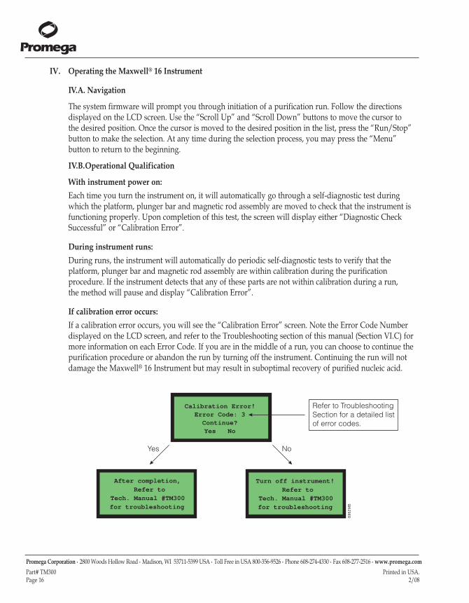
IV. Operating the Maxwell® 16 Instrument
IV.A. Navigation
The system firmware will prompt you through initiation of a purification run. Follow the directionsdisplayed on the LCD screen. Use the “Scroll Up” and “Scroll Down” buttons to move the cursor to the desired position. Once the cursor is moved to the desired position in the list, press the “Run/Stop”button to make the selection. At any time during the selection process, you may press the “Menu”button to return to the beginning.
IV.B.Operational Qualification
With instrument power on:Each time you turn the instrument on, it will automatically go through a self-diagnostic test duringwhich the platform, plunger bar and magnetic rod assembly are moved to check that the instrument isfunctioning properly. Upon completion of this test, the screen will display either “Diagnostic CheckSuccessful” or “Calibration Error”.
During instrument runs:During runs, the instrument will automatically do periodic self-diagnostic tests to verify that theplatform, plunger bar and magnetic rod assembly are within calibration during the purificationprocedure. If the instrument detects that any of these parts are not within calibration during a run, the method will pause and display “Calibration Error”.
If calibration error occurs:If a calibration error occurs, you will see the “Calibration Error” screen. Note the Error Code Numberdisplayed on the LCD screen, and refer to the Troubleshooting section of this manual (Section VI.C) formore information on each Error Code. If you are in the middle of a run, you can choose to continue thepurification procedure or abandon the run by turning off the instrument. Continuing the run will notdamage the Maxwell® 16 Instrument but may result in suboptimal recovery of purified nucleic acid.
Promega Corporation · 2800 Woods Hollow Road · Madison, WI 53711-5399 USA · Toll Free in USA 800-356-9526 · Phone 608-274-4330 · Fax 608-277-2516 · www.promega.comPart# TM300 Printed in USA.Page 16 2/08
tm300.0208_Corrected.qxp 3/11/2008 10:41 AM Page 16

IV.C. Sample Purification
Placement of sample cartridges in the Maxwell® 16 Instrument is illustrated in Figure 5. Please refer to theMaxwell® 16 Blood DNA Purification Kit Technical Manual (#TM301) for detailed instructions on cartridgeand sample preparation and purification.
The Maxwell® 16 reagent cartridges are designed to be used with potentially infectious substances.Users should wear the appropriate protection (i.e., gloves, goggles, etc.) when handling infectioussubstances. Users should adhere to their institutional guidelines for the handling and disposal of allinfectious substances when used with this system.
The Maxwell® 16 reagent cartridges contain potentially hazardous chemicals. Users should wearprotective gloves when handling the reagent cartridges. Users should follow their institutionalguidelines for disposal.
IV.D. Minimizing Cross-Contamination
Users should follow standard laboratory procedures to avoid cross-contamination of samples. Weargloves during all procedures, and change gloves often. Use aerosol-resistant pipet tips whentransferring samples to minimize the potential for cross-contamination.
Promega Corporation · 2800 Woods Hollow Road · Madison, WI 53711-5399 USA · Toll Free in USA 800-356-9526 · Phone 608-274-4330 · Fax 608-277-2516 · www.promega.comPrinted in USA. Part# TM3002/08 Page 17
6916
TB
Figure 5. Placement of sample cartridgesinto the Maxwell® 16 Instrument. Sample cartridges are placed in theMaxwell® 16 Cartridge Rack. The samplecartridges are then removed from theMaxwell® 16 Cartridge Rack and placed ontothe instrument platform.
tm300.0208_Corrected.qxp 3/11/2008 10:41 AM Page 17

V. Periodic Cleaning and Maintenance
The Maxwell® 16 Instrument requires minimal maintenance. However, it is important to clean theinstrument at regular intervals. If samples or reagents have been spilled, it is important to clean theinstrument to avoid damage. Most parts of the Maxwell® 16 Instrument have an anodization coating,which forms a durable, easily cleaned barrier with the metal.
Always turn off and unplug the instrument before cleaning.
V.A. General Care
• Wipe up any spills immediately.
• After each use, clean the instrument by wiping off the magnetic rod assembly, plunger bar, andplatform using a cloth dampened with deionized water or 70% ethanol. Do not use othersolvents or abrasive cleaners.
Note: Wear gloves. If the instrument is used with biohazardous materials, dispose of anycleaning materials used in accordance with your institutional guidelines.
• Periodically wipe the outside of the instrument using a cloth dampened with deionized wateror 70% ethanol.
• Keep the cooling vents in the back of the machine clear of dust.
• Do not remove the Maxwell® 16 Instrument case for cleaning. This will void the warranty.
• Do not use a spray bottle to soak instrument surfaces with large volumes of liquid.
• Never allow liquids to sit on instrument surfaces for extended periods of time.
• Keep all moisture away from the heated elution tube slots to prevent damage to the heatingelements.
• If the linear slides (see Figure 3, Section II) for the platform need to be cleaned, use only a drypaper towel. If they have been contaminated with any liquid, wipe off excess liquid and followthe lubrication guidelines in Section V.C., or contact Promega Technical Services for assistance.
• If any of the hardware accessories need to be cleaned (i.e., cartridge or elution racks), wipethem with a cloth dampened with deionized water or 70% ethanol.
Promega Corporation · 2800 Woods Hollow Road · Madison, WI 53711-5399 USA · Toll Free in USA 800-356-9526 · Phone 608-274-4330 · Fax 608-277-2516 · www.promega.comPart# TM300 Printed in USA.Page 18 2/08
tm300.0208_Corrected.qxp 3/11/2008 10:41 AM Page 18

V.B. Removal of Magnetic Rod Assembly
If the plungers are inadvertently left out during a run or placed in the wrong starting position, themachine may go through a run with the magnetic rods unprotected. If this happens, the magneticrod assembly must be removed for cleaning.
1. Turn off the power and unplug the instrument. This will release the motors so that the headscan be gently moved to allow easier access to the magnetic rod assembly.
2. Gently and slowly, with constant pressure on both the right and left side, push the plungerbar and the magnetic rod assembly down to their lowest positions. Do not push the plungerbar and magnetic rod assembly too fast. Doing so could result in damage to the instrument’selectronics.
3. Unscrew and remove the three thumbscrews on top of the magnetic rod assembly (Figure 6).
4. Once the three thumbscrews are removed, gently lift up the magnetic rod assembly to remove it.
5. To clean the magnetic rod assembly, wipe with a soft paper towel dampened with deionizedwater or 70% ethanol. Removal of paramagnetic particles from the magnetic rod assemblywill require multiple wipes with a damp cloth.
6. If the magnetic rod assembly cannot be cleaned, please contact Promega for assistance.
7. Replace the magnetic rod assembly, and firmly tighten the three thumbscrews.
V.C. Periodic Maintenance
Linear Slides: If the linear slides become sticky, they may be lubricated with light machine oil. Usea cotton swab, and apply only as much as is needed to make the heads and plate slide easily. Donot get oil on the black drive belts.
Belts: Inspect the belts periodically. If excessive wear or excessive slack is noted, contact Promegaor your local Promega representative, and arrangements will be made to service the instrument.
Promega Corporation · 2800 Woods Hollow Road · Madison, WI 53711-5399 USA · Toll Free in USA 800-356-9526 · Phone 608-274-4330 · Fax 608-277-2516 · www.promega.comPrinted in USA. Part# TM3002/08 Page 19
Figure 6. The thumbscrews on the top of the magnetic rod assembly.51
89T
B
tm300.0208_Corrected.qxp 3/11/2008 10:41 AM Page 19

VI. Troubleshooting
VI.A.General Troubleshooting
Symptoms Causes and Comments
Expected method not available. Instrument configuration has been changed to Research or Forensic mode. Confirm theconfiguration by turning the instrument off and then on again (See Section VIII.A). Tochange the operational mode and hardware settings, follow the directions in SectionVIII.A(ii), selecting “Clinical” from the Operational Setup screen, and “SEV”from theHardware Setup screen.
The instrument is making anunusual, rapid clicking noisewhen it is turned on.
• Verify that the Magnetic Rod Assembly/Plunger Bar shipping anchors and Platform shippinganchors have been removed.
• One of the machine sensors might have a dust particle interfering with it. Contact Promega oryour local Promega representative for assistance with sensor cleaning.
The LCD screen does not lightup when the instrument isturned on.
If you cannot hear the motors running:• Check that the unit is plugged into a working electrical outlet • Verify that the plug is securely connected to the back of the instrument. • A 3-amp fuse protects the instrument electronics and is located next to the power switch. If
the fuse is blown, identify and correct the cause. Never replace this fuse with a fuse rated foran amperage higher than 3A.
• Contact Promega or your local Promega representative for service.
If you can hear the motors running:• Either a cable has become disconnected from the LCD screen, or the LCD screen is broken or
damaged. Contact Promega or your local Promega representative for service.
The machine makes unusualnoises during the run.
The machine will make some noise during a typical run. Unusual (or louder than usual) noisesmay indicate that the heads are sticking. Continued operation under these conditions can causedamage to the instrument. Heads that are sticking may be lubricated with light machine oil. Donot get any oil on the drive belts. Use a small amount of oil on a cotton swab. If this does notcorrect the problem, contact Promega or your local Promega representative for service.
Heater error at the elution step. The electrical heating system is not working properly. Contact Promega or your local Promegarepresentative for service.
Plungers are not completelystripped off the rods at the end of the run.
Always be careful to check that plungers are clear of the magnetic rod assembly beforeextending the platform out from inside the instrument. If the problem occurs consistently, checkthat the magnetic rods are clean. Wipe them down carefully with a damp cloth. Do not reuseplungers. If plungers are consistently left on, contact Promega or your local Promegarepresentative for service.
Promega Corporation · 2800 Woods Hollow Road · Madison, WI 53711-5399 USA · Toll Free in USA 800-356-9526 · Phone 608-274-4330 · Fax 608-277-2516 · www.promega.comPart# TM300 Printed in USA.Page 20 2/08
tm300.0208_Corrected.qxp 3/11/2008 10:41 AM Page 20

Promega Corporation · 2800 Woods Hollow Road · Madison, WI 53711-5399 USA · Toll Free in USA 800-356-9526 · Phone 608-274-4330 · Fax 608-277-2516 · www.promega.comPrinted in USA. Part# TM3002/08 Page 21
Promega Corporation · 2800 Woods Hollow Road · Madison, WI 53711-5399 USA · Toll Free in USA 800-356-9526 · Phone 608-274-4330 · Fax 608-277-2516 · www.promega.comPrinted in USA. Part# TM3002/08 Page 21
Symptoms Causes and Comments
The buttons don’t work. Some of the buttons are ignored during processing. If a button is not working consistently,please contact Promega or your local Promega representative. Do not use spray cleaner on thekeypad, as it can seep in and short out the keyboard.
When I close (or open) the door,the program does not advance.
There may be a problem with the door sensor. Please contact Promega or your local Promegarepresentative for service.
The machine runs but does notadvance to the “Run” screen.
A sensor for one of the heads may be failing, or a belt may be slipping. Please contactPromega or your local Promega representative for service.
Poor sample quality, low yield or low purity.
See the troubleshooting section of the Technical Manual supplied with your Maxwell® 16Purification Kit for more information.
Expected methods are not shownon the LCD screen.
Verify the firmware setup. Refer to Section III.C.
Can I change the steps in aprotocol?
No. Contact Promega or your local Promega representative for firmware upgrades. As newpurification kits become available, new automated methods will be offered. Reagents arepredispensed and optimized to work with the preprogrammed automated methods.
VI.B. Power Failure
Power failure occurs duringinstrument run.
To recover your samples after a power failure, first ensure that the particles are in one of thewells of the cartridge and are not attached to the plunger. If the power failure occurred at apoint where the magnetic particles were captured on the outside of the plungers, manuallymove the plungers up and down in the wells to wash off the particles. Then manually removethe plungers from the instrument and restart the purification, from the beginning, with newplungers.
tm300.0208_Corrected.qxp 3/11/2008 10:41 AM Page 21

VI. Troubleshooting (continued)
VI.C.Error Messages
Promega Corporation · 2800 Woods Hollow Road · Madison, WI 53711-5399 USA · Toll Free in USA 800-356-9526 · Phone 608-274-4330 · Fax 608-277-2516 · www.promega.comPart# TM300 Printed in USA.Page 22 2/08
Symptoms Causes and Comments
Calibration error: Error Code 1. Error Code 1 indicates a Platform calibration error. • Verify that there are no obstructions behind or in front of the platform that prevent it from
moving back and forward freely.• Turn the instrument off, wait a few seconds, then turn the instrument back on. If the
calibration error persists, please contact Promega or your local Promega representative forservice.
Calibration error: Error Code 2. Error code 2 indicates a Plunger Bar calibration error.• Verify that there are no solid particulates inside Well #1 of the cartridge. Solid particulates
may obstruct the plunger from moving freely to the bottom of Well #1 during processing.• Ensure the cartridges are seated properly onto the platform.• If the error occurs during plunger loading, ensure the hardware configuration matches the
firmware settings. Select “No” after the “Continue?” prompt on the LCD screen (see SectionIV.B).
• Verify that the shipping anchors have been removed. Refer to Section III.B. • Turn the instrument off, wait a few seconds, then turn the instrument back on. If the
calibration error persists, please contact Promega or your local Promega representative forservice.
Calibration error: Error Code 3. Error code 3 indicates a Magnetic Rod Assembly calibration error• Verify that the shipping anchors have been removed. Refer to Section III.B.• Verify that the Magnetic Rod Assembly is attached properly. Refer to Section VIII.B.• Turn the instrument off, wait a few seconds, then turn the instrument back on. If the
calibration error persists please contact Promega or your local Promega representative forservice.
One of the following errormessages appears in English.
“Error!”“Low Temp Detect”“Press Run/Stop key”“Time: 00h 00m 00s”“Temp Sensor check!”“By agitation”“Press Run/Stop key”“Waiting!”“Heating the Block”
These messages indicate that a thermocouple is detecting a temperature issue. Pressing theRun/Stop key will clear these errors, and the run will continue without heat. DNA yield will bereduced. If you choose to continue the run, check the quality of the purified DNA before using itin downstream diagnostic applications. Contact Promega or your local Promega representativefor service.
tm300.0208_Corrected.qxp 3/11/2008 10:41 AM Page 22

VII. Appendix I: Firmware Updates, Instrument Return, and Warranty Information
VII.A. Updating Firmware
As Promega releases new purification kits, new versions of firmware may be required. The firmwareversion installed on your instrument can be verified by turning the machine off and then on again. Theinitial screen will display the version number of the firmware loaded on the instrument. Please note thefirmware version currently installed on your instrument before contacting Promega or your local Promegarepresentative for service or for new firmware.
Firmware is updated using the RS-232 port on the back of the instrument. Firmware can be updated fromany computer (Microsoft Windows® 95 or higher) with an available serial port.
For clinical use, firmware version 4.40 or greater is required. Do not install firmware versions below 4.40.
1. Plug the provided RS-232 Cable into the back of the instrument and into a serial port on yourcomputer. Note whether the cable is plugged into COM1 or COM2.
2. Obtain the firmware upgrade program from Promega or your local Promega representative. Save theunzipped file to your hard drive, and follow the directions provided with the new firmware.
3. Double-click on the file icon to open the download program. Select the COM port into which the RS-232 Cable is connected. Click the “Download” button, and wait until the program is complete. Theinstrument should reset itself. Turn the unit off and then back on again. The screen will display thenew firmware version. Disconnect the RS-232 Cable from the computer. The RS-232 Cable may be leftplugged into the instrument if desired.
Please contact Promega or your local Promega representative for assistance if you encounter any problemsduring the firmware upgrade process.
VII.B. Instrument Return
The Maxwell® 16 Instrument is designed to provide consistent performance with little maintenance. If aproblem arises with your instrument, please contact Promega or your local Promega representative forsupport. If further action is required, repair options will be presented and a return authorizationassigned if necessary. Promega is not responsible for instrumentation returned without anauthorization number. When you ship the instrument for service, please remember to:
1. Obtain return authorization from Promega.
2. Decontaminate the instrument (see Section VII.D for Decontamination Instructions).
3. Affix a signed and dated Certificate of Decontamination to the outside of the package in which theinstrument is returned (see Section VII.D). Failure to complete and attach the Certificate ofDecontamination will result in a decontamination charge.
4. Use the original packaging to ensure that no damage will occur to the instrument during shipping.Any damage will incur additional charges. Note: If the original packaging is lost or damaged, contactPromega or your local Promega representative for replacement packaging.
5. Repack the instrument according to the following instructions:
Promega Corporation · 2800 Woods Hollow Road · Madison, WI 53711-5399 USA · Toll Free in USA 800-356-9526 · Phone 608-274-4330 · Fax 608-277-2516 · www.promega.comPrinted in USA. Part# TM3002/08 Page 23
!
tm300.0208_Corrected.qxp 3/11/2008 10:41 AM Page 23

VII.B. Instrument Return (continued)
Preparation of the Maxwell® 16 Instrument Prior to Repacking
1. Ensure that the cartridges and elution tubes are removed from the instrument platform.
2. Ensure that the instrument is turned off and is not plugged in.
3. Decontaminate the instrument.
Anchoring the Platform, Magnetic Rod Assembly and Plunger Bar
1. By hand, carefully push the platform back into the instrument as far as it will go. Replace the Platformshipping anchor thumbscrews (Figure 4, Section III.B) and tighten by hand to anchor the platform inplace for shipment.
2. By hand, gently lower the plunger bar and magnetic rod assembly down as far as it will go. Replacethe Magnetic Rod/Plunger Bar shipping anchor thumbscrews and tighten by hand (Figure 4, SectionIII.B).
Repacking the Maxwell® 16 Instrument
1. Place the instrument into the plastic bag.
2. Place the two foam packaging protectors on the sides of the instrument.
3. Slide the instrument into the small inside shipping box. Ensure that the top of the instrument is facingthe top of the open box.
4. Slide the small inside shipping box containing the instrument into the large outside shipping box.
5. Repack the Maxwell® 16 Instrument accessories.a. Rewrap the Cartridge Preparation Rack and Magnetic Elution Tube Rack in bubble wrap and
place on top of the instrument.b. Place the RS-232 Cable (in a reclosable bag) into the box.c. Place the Power Cable into the box.
6. Affix the Certificate of Decontamination on the outside of the shipping box. Write the returnauthorization number provided to you by Promega or your local Promega representative on theoutside of the shipping box. Seal the box securely.
VII.C. Instrument Disposal
Contact your local Promega Representative for disposal of the instrument. Please follow yourinstitutional requirements to handle the disposal of accessories.
Promega Corporation · 2800 Woods Hollow Road · Madison, WI 53711-5399 USA · Toll Free in USA 800-356-9526 · Phone 608-274-4330 · Fax 608-277-2516 · www.promega.comPart# TM300 Printed in USA.Page 24 2/08
tm300.0208_Corrected.qxp 3/11/2008 10:41 AM Page 24

Promega Corporation · 2800 Woods Hollow Road · Madison, WI 53711-5399 USA · Toll Free in USA 800-356-9526 · Phone 608-274-4330 · Fax 608-277-2516 · www.promega.comPrinted in USA. Part# TM3002/08 Page 25
VII.D. Certificate of Decontamination
Disinfection and decontamination are required prior to shipping the instrument and accessories forrepair. Returned Instruments must be accompanied by a signed and dated Certificate ofDecontamination, which must be attached to the outside packaging of the instrument.
To disinfect and decontaminate: Wipe off the magnetic rod assembly, plunger bar, inside platform,and inside and outside surfaces using a cloth dampened 70% ethanol then a cloth dampened witha 1—2% bleach solution in deionized water. Follow immediately with a cloth dampened withdeionized water to remove any residual bleach from the instrument surfaces. Repeat the procedureas many times as required to effectively disinfect and decontaminate the instrument.
Failure to confirm disinfection and decontamination will result in decontamination chargesbefore the instrument will be serviced.
Select either (A) or (B):
A. I confirm that the returned items have not been in contact with body fluids or toxic,carcinogenic, radioactive, or other hazardous materials.
B. I confirm that the returned items have been decontaminated and can be handled withoutexposing personnel to health hazards.
Circle the type of material used in the instrument: Chemical Biological Radioactive**
Briefly describe the decontamination procedure performed:
Date:
Place:
Signature:
Name (block capital letters):
** The signature of a Radiation Safety Officer is also required if the instrument was used withradioactive materials.
This instrument is certified by the undersigned to be free of radioactive contamination.
Date:
Place:
Signature:
Name (block capital letters):
tm300.0208_Corrected.qxp 3/11/2008 10:41 AM Page 25

VII.E. Warranty Information
Limited Warranty and Service Guidelines
Promega warrants to the original purchaser that the Promega Maxwell® 16 Instrument will be free from defects inmaterials and workmanship for a period of one year from the date of delivery. Promega agrees, as its soleresponsibility under this limited warranty, and upon prompt notice of a defect, to repair or replace (at Promega’sdiscretion) any instrument discovered to be defective within the warranty period. Expendable items are not coveredby this warranty. This warranty does not include repair or replacement necessitated by accident, neglect, misuse,unauthorized repair or modification of the instrument. The instrument may not be returned without a properReturn Authorization Number from Promega, as described below.
This warranty and the remedies set forth herein are exclusive and in lieu of all other express or implied warranties(including implied warranties of merchantability, fitness for a particular purpose and noninfringement), and noother warranties shall be binding upon Promega. In no event shall Promega be liable for any special, incidental orconsequential damages resulting from the use or malfunction of this instrument or the system with which it is used.
In addition to the standard limited warranty that comes with the Maxwell® 16 Instrument, extended and premiumwarranties are available for purchase. If you purchased an extended or premium warranty for your Maxwell® 16Instrument, please refer to those specific warranty terms.
To obtain service during the warranty period, please take the following steps:
1. Write or call the company that sold you the instrument and describe as precisely as possible the nature of theproblem.
2. Carry out minor adjustments or tests as suggested by your technical contact.
3. If the instrument is still not functioning properly, YOU MUST OBTAIN A PROMEGA RETURNAUTHORIZATION NUMBER.
4. Before returning the instrument, you will be responsible for cleaning it and providing a Certificate ofDecontamination to Promega in accordance with instructions.
5. After obtaining a Return Authorization Number and signing the Certificate of Decontamination, pack theinstrument carefully (damage incurred in shipping due to improper packaging is not Promega’sresponsibility), write the Return Authorization Number on the outside of the package and ship it to theaddress provided by your technical contact.
6. Shipping to and from Promega will be paid by Promega pursuant to directions to be provided. Theinstrument will be repaired free of charge for all customers within their warranty period.
7. Under no circumstance can an instrument be returned without proper authorization. This authorization isneeded to ensure that the problem is not a minor problem that can be easily handled in your laboratory andto determine the nature of the problem so that repairs can be handled appropriately.
Out of Warranty Service
Contact Promega or your local Promega representative. We will be happy to assist you by telephone at no charge.Repair service, if needed, will be billed at a flat rate to be agreed upon in advance. Your invoice will includeshipping.
Promega Corporation · 2800 Woods Hollow Road · Madison, WI 53711-5399 USA · Toll Free in USA 800-356-9526 · Phone 608-274-4330 · Fax 608-277-2516 · www.promega.comPart# TM300 Printed in USA.Page 26 2/08
tm300.0208_Corrected.qxp 3/11/2008 10:41 AM Page 26

Promega Corporation · 2800 Woods Hollow Road · Madison, WI 53711-5399 USA · Toll Free in USA 800-356-9526 · Phone 608-274-4330 · Fax 608-277-2516 · www.promega.comPrinted in USA. Part# TM3002/08 Page 27
VIII. Appendix II: Research and Forensic Applications of the Maxwell® 16 System
This section of the Technical Manual discusses use of the Maxwell® 16 System for Research and Forensicapplications. Operation of the instrument in Research and Forensic modes, or with kits other than Cat.# AS1015, has not been demonstrated to comply with EU Directive 98/79/EC on in vitro diagnosticmedical devices.
The Maxwell® 16 Clinical Instrument (Cat.# AS2050) is supplied configured for use in clinical mode with SEV(Standard Elution Volume) hardware. When used for research or forensic applications, the instrument maybe configured with SEV or LEV (Low Elution Volume) hardware for different elution volume preferences.See Section VIII.B for instructions on how to configure your instrument in SEV or LEV format.
VIII.A. Operational Mode Setup Requirements
The Maxwell® 16 Instrument has multiple operational modes, depending on the procedure and thepurification kit used. Table 2 lists the hardware configuration and operational mode requirements forthe Maxwell® 16 Purification Kits. Please refer to the Technical Manual supplied with your specificpurification kit for further information on the operational mode required.
Table 2. Hardware Configuration and Operational Mode Setup Requirements for Research andForensic Applications.
Please ensure that you select the operational mode that is required for your hardware configuration. Failure touse the correct operational mode and hardware configuration will cause damage to the instrument.
Maxwell® 16 Kit Purification Procedure
FirmwareOperational Mode
HardwareConfiguration
Maxwell® 16 gDNAPurification Kits (Cat.# AS1010, AS1020, AS1030)
gDNA Research (Rsch)
Standard ElutionVolume(SEV)
Maxwell® 16 PolyhistidineProtein Purification Kit (Cat.#AS1060)
Polyhistidine-Tagged Protein
Research (Rsch)
Standard ElutionVolume(SEV)
Maxwell® 16 Total RNAPurification Kit (Cat.# AS1050)
Total RNA Research (Rsch)
Standard ElutionVolume(SEV)
Maxwell® 16 LEV Total RNAPurification Kits (Cat.# AS1220, AS1225)
Total RNA Research (Rsch)
Low Elution Volume(LEV)
DNA IQ™ Reference SampleKit for Maxwell® 16 (Cat.# AS1040)
Forensic gDNAReference Samples
Forensic(Fnsc)
Standard ElutionVolume(SEV)
DNA IQ™ Casework SampleKit for Maxwell® 16 LEV (Cat.# AS1210)
Forensic gDNACasework Samples
Forensic(Fnsc)
Low Elution Volume(LEV)
!
tm300.0208_Corrected.qxp 3/11/2008 10:41 AM Page 27

Promega Corporation · 2800 Woods Hollow Road · Madison, WI 53711-5399 USA · Toll Free in USA 800-356-9526 · Phone 608-274-4330 · Fax 608-277-2516 · www.promega.comPart# TM300 Printed in USA.Page 28 2/08
VIII.A. Operational Mode Setup Requirements (continued)
(i) Setting the Maxwell® 16 Instrument Operational Mode
(ii) Changing the Maxwell® 16 Instrument Operational Mode
1. Make sure the instrument door is closed and turn on the Maxwell® 16 Instrument. The screen will displayboth the firmware version number and the current operational mode setting.
2. Verify that the current operational mode displayed matches theoperational mode required by both the installed hardware and thepurification kit to be used (see Table 2).
3. If the operational mode displayed does not match the operationalmode required by the purification kit, you will need to change theinstrument setting (see (ii) below, “Changing the Maxwell® 16Instrument Operational Mode”).
6033
ME
Fnsc
Promega MAXWELL 16 Purification System
Version 4.0
LEV
Operational Mode Setting
Rsch = ResearchFnsc = ForensicIVD = Clinical
SEV = Standard Elution VolumeLEV = Low Elution Volume
1. Press the “Menu” button to get to the Menu screen.
2. Scroll down to move the cursor to “Setup”. Press “Run/Stop” toselect “Setup”.
5314
MA
1.2. Demo3. Setup
Run====Menu====
3. Scroll up/down to move the cursor to the desired operationalmode. Press “Run/Stop” to select.
Refer to Table 2 for information on the operational mode requiredfor research and forensic Maxwell® 16 Purification Kits.
5840
MB
1.Research Mode 2.Forensic Mode 3.Clinical
==Operational Setup==
4. Scroll down to move the cursor to the desired hardware mode. If the instrument is configured with the Standard Elution Volumehardware, select “SEV”. If the instrument is configured with theLow Elution Volume hardware, select “LEV”. Press “Run/Stop” to select.
6035
MA
1.SEV Hardware2.LEV Hardware
==Hardware Setup==
!
tm300.0208_Corrected.qxp 3/11/2008 10:41 AM Page 28

Promega Corporation · 2800 Woods Hollow Road · Madison, WI 53711-5399 USA · Toll Free in USA 800-356-9526 · Phone 608-274-4330 · Fax 608-277-2516 · www.promega.comPrinted in USA. Part# TM3002/08 Page 29
5. If the hardware mode in the firmware has changed, the following LCD screens will appear,prompting the user to change the hardware. Failure to change the hardware will result indamage to the instrument. Directions for changing the hardware are provided in SectionVIII.B.If changing from LEV to SEV, the following screens will appear:
6214
MB
==Hardware Setup==Remove LEV hardware:Magnet & Plunger BarPress Run/Stop Key
==Hardware Setup==Add SEV hardware:Magnet Assembly
Press Run/Stop Key
If changing from SEV to LEV, the following screens will appear:
6220
MB
==Hardware Setup==Remove SEV hardware:
Magnet AssemblyPress Run/Stop Key
==Hardware Setup==Add LEV hardware:
Magnet & Plunger BarPress Run/Stop Key
6. The display will show the operational mode selected.Turn the instrument off and then on to cycle theinstrument power.Note: The selected operational mode or hardwaresetting will not be applied until you cycle the power.
6034
MB
Forensic Mode SetLEV Hardware
Please Cycle Power
==Setup Verification==
7. When you turn the instrument back on, verify theinstrument’s operational mode setting on the displayscreen.
Fnsc
Promega MAXWELL 16 Purification System
Version 4.0
LEV
Operational Mode Setting
Rsch = ResearchFnsc = ForensicIVD = Clinical
SEV = Standard Elution VolumeLEV = Low Elution Volume
tm300.0208_Corrected.qxp 3/11/2008 10:41 AM Page 29

Promega Corporation · 2800 Woods Hollow Road · Madison, WI 53711-5399 USA · Toll Free in USA 800-356-9526 · Phone 608-274-4330 · Fax 608-277-2516 · www.promega.comPart# TM300 Printed in USA.Page 30 2/08
VIII.B. Reconfiguring the Maxwell® 16 Instrument Hardware
The Maxwell® 16 Instrument can be configured in SEV (Standard Elution Volume) or LEV (Low ElutionVolume) format for different sample elution volume preferences. To reconfigure your instrument for adifferent elution volume preference, you will need the appropriate Conversion Kit (see Section VIII.C).The Maxwell® 16 Instrument (Cat.# AS2050) is supplied in SEV format. To convert an SEV instrument toLEV format, the LEV Conversion Kit for Maxwell® 16 (Cat.# AS1250) is required.
(i) Changing from Standard to LEV Configuration
Note: Do not reconfigure the instrument while samples or reagent cartridges are in place on theinstrument platform. To avoid potential exposure to contaminants, clean the instrument according tothe instructions in Section V.A before you begin.
1. Ensure that the power is turned off and the instrument is unplugged. This will release the motorsso that the heads can be gently moved to allow easier access to the hardware assemblies.
2. Gently and slowly, with constant pressure on both the right and left side, push the blue PlungerBar and the blue Magnetic Rod Assembly down to their lowest positions. Do not push too fast, asthis could cause damage to the instrument’s electronics.
!
3. Unscrew the three thumbscrews on top of themagnetic rod assembly.
Thumbscrew
tm300.0208_Corrected.qxp 3/11/2008 10:41 AM Page 30

Promega Corporation · 2800 Woods Hollow Road · Madison, WI 53711-5399 USA · Toll Free in USA 800-356-9526 · Phone 608-274-4330 · Fax 608-277-2516 · www.promega.comPrinted in USA. Part# TM3002/08 Page 31
4. Gently lift up the SEV Magnetic Rod Assembly andremove it.
5. Insert the black LEV Plunger Bar Adaptor onto thebottom of the remaining arm. Make sure that the sidecontaining the screws faces upward. Several magnetswill “click” and hold the LEV Plunger Bar Adaptor inplace once it is attached. The LEV Plunger bar shouldthen be fairly difficult to remove.
6. Insert the black LEV Magnetic Rod Assembly. Thescrews should be facing toward you. Press firmly toplace the LEV Magnetic Rod Assembly in position. Itwill fit tightly into place.
6391
TA
Orientation of the Magnetic Rod Assembly
front
back
7. Secure the LEV Magnetic Rod Assembly with the threethumbscrews from the standard magnetic rodassembly, and hand-tighten. Complete theconfiguration by updating the Firmware to the LEVsetting (Section VIII.A).
Failure to change the instrument firmwareoperational mode from SEV to LEV will causedamage to the instrument.
!
SEV Magnetic Rod Assembly
LEV Plunger Bar Adaptor
tm300.0208_Corrected.qxp 3/11/2008 10:42 AM Page 31

(ii) Changing from LEV to Standard Configuration
Promega Corporation · 2800 Woods Hollow Road · Madison, WI 53711-5399 USA · Toll Free in USA 800-356-9526 · Phone 608-274-4330 · Fax 608-277-2516 · www.promega.comPart# TM300 Printed in USA.Page 32 2/08
1. Ensure that the power is turned off and the instrument is unplugged. This will release the motors so thatthe heads can be moved gently to allow easier access to the hardware assemblies.
2. Gently and slowly, with constant pressure on both the right and left sides, push the black LEV MagneticRod Assembly down to the lowest position. Do not push too fast, as this could result in damage to theinstrument’s electronics.
3. Unscrew the three thumbscrews on top of the magneticrod assembly.
4. Gently lift up the LEV Magnetic Rod Assembly to remove it.
5. Pull down on the LEV Plunger Bar Adaptor to release the magnets that hold it in place. Hint: Pull down at an angle so that theback of the magnet is released first.
Remove the black LEV Plunger Bar Adaptor.
6. Insert the blue SEV Magnetic Rod Assembly.
7. Secure the Magnetic Rod Assembly with the three thumbscrews, and hand-tighten.
8. Complete the configuration by updating the Firmware to the SEV setting (Section VIII.A).
Failure to change the instrument firmware operational mode from LEV to SEV will cause damage tothe instrument.
LEV Magnetic Rod Assembly
LEV Plunger Bar Adaptor
SEV Magnetic Rod Assembly
!
Thumbscrew
tm300.0208_Corrected.qxp 3/11/2008 10:43 AM Page 32

Promega Corporation · 2800 Woods Hollow Road · Madison, WI 53711-5399 USA · Toll Free in USA 800-356-9526 · Phone 608-274-4330 · Fax 608-277-2516 · www.promega.comPrinted in USA. Part# TM3002/08 Page 33
VIII.C. Instrument Accessories and Purification Kits for Research and Forensic Use
DNA Purification Kits
Product Size Cat.#Maxwell® 16 Blood DNA Purification Kit 48 preps AS1010For Laboratory Use. Sufficient for 48 automated isolations from up to 400μl whole blood samples. Product Size Cat.#Maxwell® 16 Cell DNA Purification Kit 48 preps AS1020For Laboratory Use. Sufficient for 48 automated isolations from tissue culture or bacterial cells. Product Size Cat.#Maxwell® 16 Tissue DNA Purification Kit 48 preps AS1030For Laboratory Use. Sufficient for 48 automated isolations from up to 50mg tissue samples.
RNA Purification Kits
Product Size Cat.#Maxwell® 16 Total RNA Purification Kit 48 preps AS1050For Laboratory Use. Sufficient for 48 automated isolations from tissue, cells or blood sample types. Product Size Cat.#Maxwell® 16 Tissue LEV Total RNA Purification Kit 48 preps AS1220For Laboratory Use. Sufficient for 48 automated isolations from up to 25mg tissue samples. Product Size Cat.#Maxwell® 16 Cell LEV Total RNA Purification Kit 48 preps AS1225For Laboratory Use. Sufficient for 48 automated isolations from up to 1 × 10⁶ tissue culture cells.
Forensic or Paternity Lab-Related Products
Product Size Cat.#DNA IQ™ Reference Sample Kit for Maxwell® 16 48 preps AS1040Sufficient for 48 automated isolations from forensic or paternity reference sample types. For Research Use Only. Not for use in diagnostic procedures.Product Size Cat.#DNA IQ™ Casework Sample Kit for Maxwell® 16 48 preps AS1210Sufficient for 48 automated isolations from forensic casework sample types. For Research Use Only. Not for use in diagnostic procedures.
Protein Purification
Product Size Cat.#Maxwell® 16 Polyhistidine Protein Purification Kit 48 preps AS1060Sufficient for 48 automated isolations.
tm300.0208_Corrected.qxp 3/11/2008 10:43 AM Page 33

VIII.C. Instrument Accessories and Purification Kits for Research and Forensic Use (continued)
Instrument Accessories
Product Cat.#LEV Conversion Kit for Maxwell® 16 AS1250Required to configure the Maxwell® 16 Instrument in LEV (low elution volume) format. Includes:
• 1 LEV Magnetic Rod Assembly• 1 LEV Plunger Bar Adaptor• 1 Maxwell® 16 LEV Cartridge Rack• 1 Quick Start Guide
Product Cat.#Maxwell® 16 LEV Cartridge Rack (for use with LEV configuration) AS1251Maxwell® 16 Cartridge Rack (for use with standard configuration) AS1201Maxwell® 16 Magnetic Elution Rack (for use with standard configuration) AS1202
Promega Corporation · 2800 Woods Hollow Road · Madison, WI 53711-5399 USA · Toll Free in USA 800-356-9526 · Phone 608-274-4330 · Fax 608-277-2516 · www.promega.comPart# TM300 Printed in USA.Page 34 2/08
tm300.0208_Corrected.qxp 3/11/2008 10:43 AM Page 34

Promega Corporation · 2800 Woods Hollow Road · Madison, WI 53711-5399 USA · Toll Free in USA 800-356-9526 · Phone 608-274-4330 · Fax 608-277-2516 · www.promega.comPrinted in USA. Part# TM3002/08 Page 35
(a)Patent Pending.(b)U.S. Pat. Nos. 6,027,945, 6,368,800 and 6,673,631, Australian Pat. No. 732756, European Pat. No. 1 204 741 and Mexican Pat. No. 209436 have been issued to Promega Corporationfor methods of isolating biological target materials using silica magnetic particles and simultaneous isolation and quantitation of DNA. Other patents are pending.(c)Australian Pat. No. 730718, Singapore Pat. No. 64532 and Korean Pat. No. 486402 have been issued to Promega Corporation for an improved filtration system and method. Otherpatents are pending.© 2008 Promega Corporation. All Rights Reserved.Maxwell is a registered trademark of Promega Corporation. DNA IQ is a trademark of Promega Corporation.Products may be covered by pending or issued patents or may have certain limitations. Please visit our Web site for more information.All prices and specifications are subject to change without prior notice.Product claims are subject to change. Please contact Promega Technical Services or access the Promega online catalog for the most up-to-date information on Promega products.
tm300.0208_Corrected.qxp 3/11/2008 10:49 AM Page 35

Promega Corporation · 2800 Woods Hollow Road · Madison, WI 53711-5399 USA · Toll Free in USA 800-356-9526 · Phone 608-274-4330 · Fax 608-277-2516 · www.promega.comPart# TM300 Printed in USA.Page 36 2/08
tm300.0208_Corrected.qxp 3/11/2008 10:49 AM Page 36

AF 9 T M3 0 0 0 2 0 8 T M3 0 0
Promega CorporationMadison, WI USA 53711
Promega Corporation • 2800 Woods Hollow Road • Madison, WI 53711-5399 USA Telephone 608-274-4330 • Fax 608-277-2601w w w . p r o m e g a . c o m
tm300.0208_Corrected.qxp 3/11/2008 10:43 AM Page b