Embed Size (px)
Citation preview

Applied Energy 88 (2011) 4120–4127
Contents lists available at ScienceDirect
Applied Energy
journal homepage: www.elsevier .com/ locate/apenergy
Maximisation of heat transfer in a coil in tank PCM cold storage system
A. Castell a,⇑, M. Belusko b, F. Bruno b, L.F. Cabeza a
a GREA Innovació Concurrent, Universitat de Lleida Edifici CREA, Pere de Cabrera s/n, 25001 Lleida, Spainb Institute for Sustainable Systems and Technologies, University of South Australia, Mawson Lakes Boulevard, Mawson Lakes, SA 5095, Australia
a r t i c l e i n f o
Article history:Received 24 September 2010Received in revised form 8 March 2011Accepted 30 March 2011Available online 6 May 2011
Keywords:PCMCold storage tankCoil in tankHeat transfer
0306-2619/$ - see front matter � 2011 Elsevier Ltd. Adoi:10.1016/j.apenergy.2011.03.046
⇑ Corresponding author. Tel.: +34 973 003577; fax:E-mail address: [email protected] (A. Castell).
a b s t r a c t
Thermal energy storage systems for both heat and cold are necessary for many industrial processes. Highenergy density and high power capacity are desirable properties of the storage. The use of latent heatincreases the energy density of the storage tank with high temperature control close to the melting point.Tube in PCM tank is a very promising system that provides high packing factor. This work presents anexperimental study of a PCM tank for cold storage applications. Two different configurations and differ-ent flow rates of the heat transfer fluid were studied. The effectiveness of the PCM storage system wasdefined as that of a heat exchanger. The results showed that the heat exchange effectiveness of the sys-tem did not vary with time, decreased with increasing flow rate and increased with increasing heat trans-fer area. The effectiveness was experimentally determined to only be a function of the ratio _m/A. Thisequation was found to be adequately be used to design a PCM storage system, and a case study is pre-sented. It was shown that the tube in tank design together with a low temperature PCM is suitable asa thermal storage facility for cold storage.
� 2011 Elsevier Ltd. All rights reserved.
1. Introduction
Thermal energy storage systems for both heating and coolingare necessary for many industrial processes. High energy densityand high power capacity for charging and discharging are desirableproperties of the storage system.
To date most storage facilities use a single-phase storage mate-rial for that purpose. The use of latent heat through the use ofphase change materials (PCM) increases the energy density. Thesesystems have been studied for many years, focussing on PCM sta-bility and improving heat transfer [1–4]. This research has investi-gated PCM encapsulated in different shapes in order to maximisethe storage density, as well as improving the thermal conductivityof the PCM [5]. Due to the packing factor within the PCM tank, thetraditional storage of PCM in spheres can result in a reduction ofthe effective storage density of 50% [6,7]. Other studies used PCMmodules inside water tanks with much lower packing factors [8].Recently Martin et al. developed a tube in PCM tank achieving upto 80% packing factor and good power of heat transfer [9]. This con-cept was similar to another one studied in Austria and reported inthe IEA Solar Heating and Cooling Implementing Agreement [10] aswell as been analyzed by Hamada and Fukai [11]. Finally, Mehlinget al. have developed a tube in PCM tank arrangement whichachieves packing factors of over 90% [12,13].
ll rights reserved.
+34 973 003575.
A completely different concept using direct contact PCM-HTF(heat transfer fluid) has been analyzed [14]. A cold storage usingwater as HTF and a commercial paraffin with phase change tem-perature at 7 �C was describes and studied experimentally. Someparameters were determined to be important for the behaviourof such a system and several limitations in its operation weredetected.
In another work developed by Medrano et al. different heatexchangers were tested as PCM storage systems [15]. The geome-tries studied were: (1) double pipe heat exchanger-PCM (DPHX-PCM), (2) double pipe heat exchanger-PCM matrix (DPHX-PCMmatrix), (3) double pipe heat exchanger fins-PCM (DPHX fins-PCM), (4) compact heat exchanger (comp-HX-PCM), and (5) plateheat exchanger (Plate-HX-PCM). Results showed that (2) DPHX-PCM matrix was a promising concept, presenting higher averagepower per unit area and per average temperature gradient. Theseresults highlight the interest in a more in-depth and further studyof a complete system based on such a concept.
However, limited research has investigated the use of PCM forcold storage (at temperatures between 0 �C and �40 �C). PCM rep-resent the most ideal solution for off peak storage. Most of thestudies related to cold storage have focused on PCM in spheres[16–19]. Consequently a tube in tank design for cold storage appli-cation warrants investigation.
To achieve energy savings and to operate an off-peak coolingsystem efficiently it is necessary to be able to select a PCM whichis near the temperature of the heat transfer fluid used in a typicalon peak system. The PCM freezing temperature is required to be
Nomenclature
Dt time interval (s)e effectiveness (–)A heat transfer area (m2)Cp heat capacity of the heat transfer fluid (kJ/kg K)_m mass flow rate of the heat transfer fluid (kg/s)
NTU number of transfer units (–)PF packing factor (–)Qact energy released from the tank during the phase change
(kW h)Qth maximum theoretical energy released from the tank
during the phase change (kW h)
Tin inlet temperature of the heat transfer fluid to the tank(K)
Tout outlet temperature of the heat transfer fluid of the tank(K)
TPCM phase change temperature of the PCM (K)U thermal transmittance (W/m2 K)VPCM volume of PCM (m3)Vstorage total volume of the storage (m3)
Table 1Tanks dimensions and parameters.
High PF design High HTS design
PF (–) 0.98 0.95Heat transfer surface (m2) 0.173 0.365PCM mass (kg) 30.49 29.55Energy storage capacity (kJ) 4390 4255Tank diametre (m) 0.29 0.29Tank height (m) 0.35 0.35Number of HTF passes (–) 14 32
Circuit 1 5.61HTF pipes length (m) 5.46 11.62
Circuit 2 6.01HTF pipes internal diametre (m) 0.008 0.008
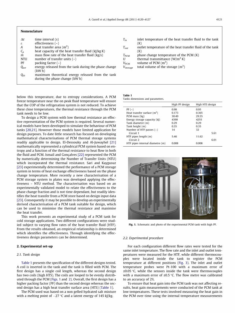
Fig. 1. Schematic and photo of the experimental PCM tank with high PF.
A. Castell et al. / Applied Energy 88 (2011) 4120–4127 4121
below this temperature, due to entropy considerations. A PCMfreeze temperature near the on peak fluid temperature will ensurethat the COP of the refrigeration system is not reduced. To achievethese close temperatures, the thermal resistance through the PCMtank needs to be low.
To design a PCM system with low thermal resistance an effec-tive representation of the PCM system is required. Several numer-ical models have been developed to simulate the behaviour of PCMtanks [20,21]. However those models have limited application fordesign purposes. To date little research has focused on developingmathematical characterisations of PCM thermal storage systemsreadily applicable to design. El-Dessouky and Al-Juwayhel [21]mathematically represented a cylindrical PCM system based on en-tropy and a function of the thermal resistance to heat flow in boththe fluid and PCM. Ismail and Gonçalves [22] represented the PCMby numerically determining the Number of Transfer Units (NTU)which incorporated the thermal resistance. Sari and Kaygusuz[23] experimentally determined the performance of a PCM storagesystem in terms of heat exchange effectiveness based on the phasechange temperature. More recently a new characterisation of aPCM storage system in plates was developed applying the effec-tiveness – NTU method. The characterisation was based on anexperimentally validated model to relate the effectiveness to thephase change fraction and is not time dependant, but readily iden-tifies the heat transfer from a PCM store based on design input data[23]. Consequently it may be possible to develop an experimentallyderived characterisation of a PCM tank suitable for design, whichcan be used to minimise the thermal resistance and maximisethe heat transfer.
This work presents an experimental study of a PCM tank forcold storage applications. Two different configurations were stud-ied subject to varying flow rates of the heat transfer fluid (HTF).From the results obtained, an empirical relationship is determinedwhich identifies the effectiveness. Through identifying the effec-tiveness design parameters can be determined.
2. Experimental set-up
2.1. Tank design
Table 1 presents the specification of the different designs tested.A coil is inserted in the tank and the tank is filled with PCM. Thefirst design has a single coil length, whereas the second designhas two coils (high HTS). The coils are looped to be evenly distrib-uted through the PCM (Figs. 1 and 2). Overall, the first design has ahigher packing factor (PF) than the second design whereas the sec-ond design has a high heat transfer surface area (HTS) (Table 1).
The PCM used was based on a non gelled hydrated salt mixturewith a melting point of �27 �C and a latent energy of 145 kJ/kg.
2.2. Experimental procedure
For each configuration different flow rates were tested for thesame inlet temperature. The flow rate and the inlet and outlet tem-peratures were measured for the HTF, while different thermocou-ples were located inside the tank to register the PCMtemperature at different positions (Fig. 3). The inlet and outlettemperature probes were Pt-100 with a maximum error of±0.05 �C, while the sensors inside the tank were thermocoupleswith a maximum error of ±0.5 �C. The flow metre was calibratedto an accuracy of 2%.
To ensure that heat gain into the PCM tank was not affecting re-sults, heat gain measurements were conducted of the PCM tank atlow temperatures. These tests involved measuring the heat gain inthe PCM over time using the internal temperature measurements
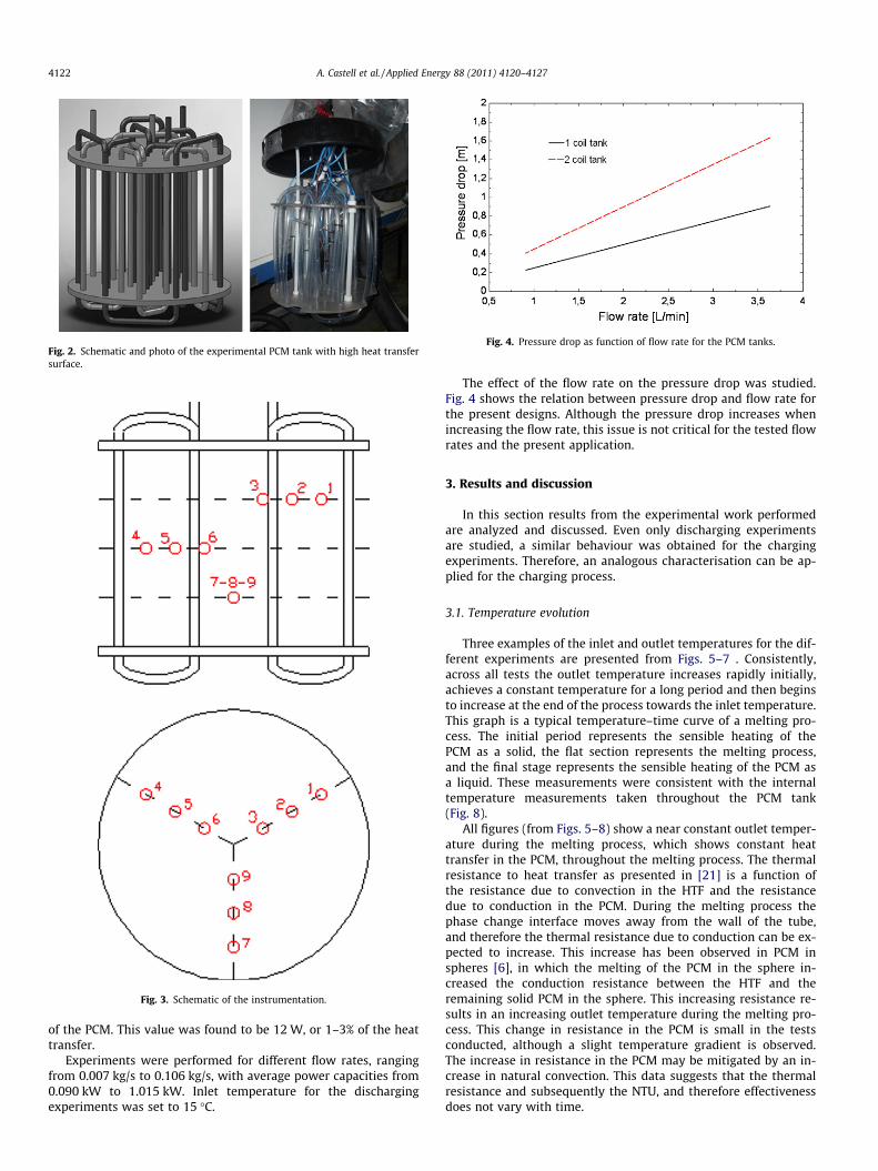
Fig. 2. Schematic and photo of the experimental PCM tank with high heat transfersurface.
Fig. 3. Schematic of the instrumentation.
Fig. 4. Pressure drop as function of flow rate for the PCM tanks.
4122 A. Castell et al. / Applied Energy 88 (2011) 4120–4127
of the PCM. This value was found to be 12 W, or 1–3% of the heattransfer.
Experiments were performed for different flow rates, rangingfrom 0.007 kg/s to 0.106 kg/s, with average power capacities from0.090 kW to 1.015 kW. Inlet temperature for the dischargingexperiments was set to 15 �C.
The effect of the flow rate on the pressure drop was studied.Fig. 4 shows the relation between pressure drop and flow rate forthe present designs. Although the pressure drop increases whenincreasing the flow rate, this issue is not critical for the tested flowrates and the present application.
3. Results and discussion
In this section results from the experimental work performedare analyzed and discussed. Even only discharging experimentsare studied, a similar behaviour was obtained for the chargingexperiments. Therefore, an analogous characterisation can be ap-plied for the charging process.
3.1. Temperature evolution
Three examples of the inlet and outlet temperatures for the dif-ferent experiments are presented from Figs. 5–7 . Consistently,across all tests the outlet temperature increases rapidly initially,achieves a constant temperature for a long period and then beginsto increase at the end of the process towards the inlet temperature.This graph is a typical temperature–time curve of a melting pro-cess. The initial period represents the sensible heating of thePCM as a solid, the flat section represents the melting process,and the final stage represents the sensible heating of the PCM asa liquid. These measurements were consistent with the internaltemperature measurements taken throughout the PCM tank(Fig. 8).
All figures (from Figs. 5–8) show a near constant outlet temper-ature during the melting process, which shows constant heattransfer in the PCM, throughout the melting process. The thermalresistance to heat transfer as presented in [21] is a function ofthe resistance due to convection in the HTF and the resistancedue to conduction in the PCM. During the melting process thephase change interface moves away from the wall of the tube,and therefore the thermal resistance due to conduction can be ex-pected to increase. This increase has been observed in PCM inspheres [6], in which the melting of the PCM in the sphere in-creased the conduction resistance between the HTF and theremaining solid PCM in the sphere. This increasing resistance re-sults in an increasing outlet temperature during the melting pro-cess. This change in resistance in the PCM is small in the testsconducted, although a slight temperature gradient is observed.The increase in resistance in the PCM may be mitigated by an in-crease in natural convection. This data suggests that the thermalresistance and subsequently the NTU, and therefore effectivenessdoes not vary with time.
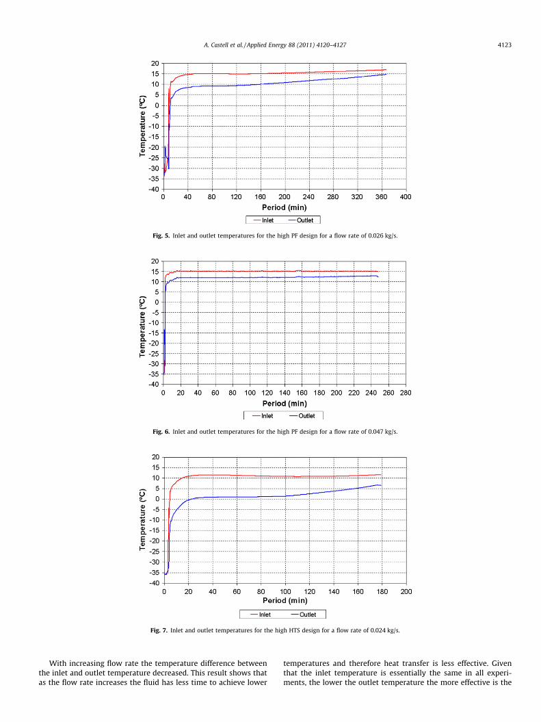
Fig. 5. Inlet and outlet temperatures for the high PF design for a flow rate of 0.026 kg/s.
Fig. 6. Inlet and outlet temperatures for the high PF design for a flow rate of 0.047 kg/s.
Fig. 7. Inlet and outlet temperatures for the high HTS design for a flow rate of 0.024 kg/s.
A. Castell et al. / Applied Energy 88 (2011) 4120–4127 4123
With increasing flow rate the temperature difference betweenthe inlet and outlet temperature decreased. This result shows thatas the flow rate increases the fluid has less time to achieve lower
temperatures and therefore heat transfer is less effective. Giventhat the inlet temperature is essentially the same in all experi-ments, the lower the outlet temperature the more effective is the
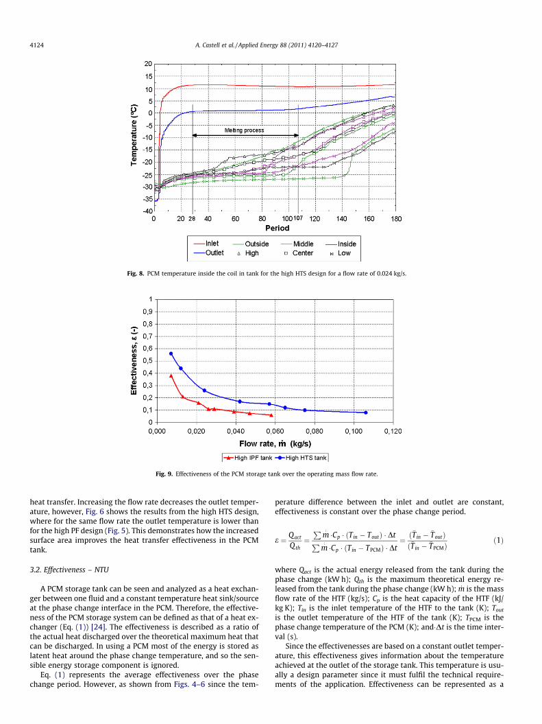
Fig. 8. PCM temperature inside the coil in tank for the high HTS design for a flow rate of 0.024 kg/s.
Fig. 9. Effectiveness of the PCM storage tank over the operating mass flow rate.
4124 A. Castell et al. / Applied Energy 88 (2011) 4120–4127
heat transfer. Increasing the flow rate decreases the outlet temper-ature, however, Fig. 6 shows the results from the high HTS design,where for the same flow rate the outlet temperature is lower thanfor the high PF design (Fig. 5). This demonstrates how the increasedsurface area improves the heat transfer effectiveness in the PCMtank.
3.2. Effectiveness – NTU
A PCM storage tank can be seen and analyzed as a heat exchan-ger between one fluid and a constant temperature heat sink/sourceat the phase change interface in the PCM. Therefore, the effective-ness of the PCM storage system can be defined as that of a heat ex-changer (Eq. (1)) [24]. The effectiveness is described as a ratio ofthe actual heat discharged over the theoretical maximum heat thatcan be discharged. In using a PCM most of the energy is stored aslatent heat around the phase change temperature, and so the sen-sible energy storage component is ignored.
Eq. (1) represents the average effectiveness over the phasechange period. However, as shown from Figs. 4–6 since the tem-
perature difference between the inlet and outlet are constant,effectiveness is constant over the phase change period.
e ¼ Q act
Q th¼P
m:�Cp � ðTin � ToutÞ � DtP
m:�Cp � ðTin � TPCMÞ � Dt
¼ ð�Tin � �ToutÞð�Tin � �TPCMÞ
ð1Þ
where Qact is the actual energy released from the tank during thephase change (kW h); Qth is the maximum theoretical energy re-leased from the tank during the phase change (kW h); _m is the massflow rate of the HTF (kg/s); Cp is the heat capacity of the HTF (kJ/kg K); Tin is the inlet temperature of the HTF to the tank (K); Tout
is the outlet temperature of the HTF of the tank (K); TPCM is thephase change temperature of the PCM (K); and�Dt is the time inter-val (s).
Since the effectivenesses are based on a constant outlet temper-ature, this effectiveness gives information about the temperatureachieved at the outlet of the storage tank. This temperature is usu-ally a design parameter since it must fulfil the technical require-ments of the application. Effectiveness can be represented as a

Fig. 10. Effectiveness of the PCM storage tank over the ratio _m/A.
Fig. 11. Comparison between e and e�PF.
Table 2Technical requirements for the application.
Temperature level required, Tout �5 �CInlet temperature to the storage, Tin 10 �CPhase change temperature of the PCM, TPCM �27 �C
A. Castell et al. / Applied Energy 88 (2011) 4120–4127 4125
function of the operating flow rate to characterize the storage sys-tem (Fig. 9).
As expected, the effectiveness for both tank designs clearlyshows an increasing effectiveness for decreasing flow rates. Sincethe main thermal resistance of the system is in the PCM itself,low flow rates result in longer circulating time of the HTF through-out the tank, making the heat transfer process more effective de-spite the lower heat transfer coefficient caused by the laminarflow rate inside the pipes.
Effectiveness defines the working conditions of the storage sys-tem and is a key parameters for the tank design since it representsthe technical specifications of the application (required tempera-ture output). However, the description of the system presentedin Fig. 9 is specific to the coil design used.
A general representation of the behaviour of the storage systemindependently of the tank configuration is presented in Fig. 10. Asshown in Eq. (2), effectiveness is a function of the NTU which is afunction of the ratio _m/A. Fig. 10 shows the effectiveness as a func-tion of this parameter and the test results for both tank designscoincide. This curve provides a characteristic design curve inde-pendent of the tank design
e ¼ f ðNTUÞ ¼ fA � Um:�Cp
!ð2Þ
Eq. (3) shows the experimentally derived effectiveness of thetube/tank design for the PCM tested. Both the design and operatingconditions are integrated in a single parameter to represent theeffectiveness of the storage.
e ¼ 0:830477� 17:2411 � _m=Aþ 184:522 � ð _m=AÞ2 � 1038:48
� ð _m=AÞ3 þ 3022:2 � ð _m=AÞ4 � 4065:01 � ð _m=AÞ5 þ 1717:23
� ð _m=AÞ6 ð3Þ
Eq. (3) was developed on a small prototype and its applicabilityto larger systems is dependant on the amount of natural convec-tion that can be expected in the PCM tank. With larger tanks, in-creased amounts of natural convection can be expected whichwill increase the heat transfer in the PCM during the phase changeprocess, and reduce the thermal resistance in the PCM. Eq. (3) willnot include this increase.
Another parameter that affects the design is the packing factor(PF). This parameter relates the total volume of PCM with the total
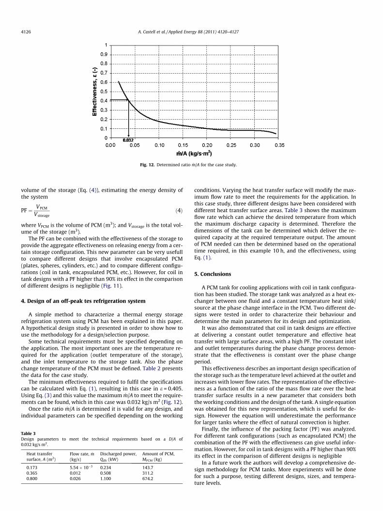
Fig. 12. Determined ratio _m/A for the case study.
4126 A. Castell et al. / Applied Energy 88 (2011) 4120–4127
volume of the storage (Eq. (4)), estimating the energy density ofthe system
PF ¼ VPCM
V storageð4Þ
where VPCM is the volume of PCM (m3); and Vstorage is the total vol-ume of the storage (m3).
The PF can be combined with the effectiveness of the storage toprovide the aggregate effectiveness on releasing energy from a cer-tain storage configuration. This new parameter can be very usefullto compare different designs that involve encapsulated PCM(plates, spheres, cylinders, etc.) and to compare different configu-rations (coil in tank, encapsulated PCM, etc.). However, for coil intank designs with a PF higher than 90% its effect in the comparisonof different designs is negligible (Fig. 11).
4. Design of an off-peak tes refrigeration system
A simple method to characterize a thermal energy storagerefrigeration system using PCM has been explained in this paper.A hypothetical design study is presented in order to show how touse the methodology for a design/selection purpose.
Some technical requirements must be specified depending onthe application. The most important ones are the temperature re-quired for the application (outlet temperature of the storage),and the inlet temperature to the storage tank. Also the phasechange temperature of the PCM must be defined. Table 2 presentsthe data for the case study.
The minimum effectiveness required to fulfil the specificationscan be calculated with Eq. (1), resulting in this case in e = 0.405.Using Eq. (3) and this value the maximum _m/A to meet the require-ments can be found, which in this case was 0.032 kg/s m2 (Fig. 12).
Once the ratio _m/A is determined it is valid for any design, andindividual parameters can be specified depending on the working
Table 3Design parameters to meet the technical requirements based on a D/A of0.032 kg/s m2.
Heat transfersurface, A (m2)
Flow rate, _m(kg/s)
Discharged power,Qdls (kW)
Amount of PCM,MPCM (kg)
0.173 5.54 � 10�3 0.234 143.70.365 0.012 0.508 311.20.800 0.026 1.100 674.2
conditions. Varying the heat transfer surface will modify the max-imum flow rate to meet the requirements for the application. Inthis case study, three different designs have been considered withdifferent heat transfer surface areas. Table 3 shows the maximumflow rate which can achieve the desired temperature from whichthe maximum discharge capacity is determined. Therefore thedimensions of the tank can be determined which deliver the re-quired capacity at the required temperature output. The amountof PCM needed can then be determined based on the operationaltime required, in this example 10 h, and the effectiveness, usingEq. (1).
5. Conclusions
A PCM tank for cooling applications with coil in tank configura-tion has been studied. The storage tank was analyzed as a heat ex-changer between one fluid and a constant temperature heat sink/source at the phase change interface in the PCM. Two different de-signs were tested in order to characterize their behaviour anddetermine the main parameters for its design and optimization.
It was also demonstrated that coil in tank designs are effectiveat delivering a constant outlet temperature and effective heattransfer with large surface areas, with a high PF. The constant inletand outlet temperatures during the phase change process demon-strate that the effectiveness is constant over the phase changeperiod.
This effectiveness describes an important design specification ofthe storage such as the temperature level achieved at the outlet andincreases with lower flow rates. The representation of the effective-ness as a function of the ratio of the mass flow rate over the heattransfer surface results in a new parameter that considers boththe working conditions and the design of the tank. A single equationwas obtained for this new representation, which is useful for de-sign. However the equation will underestimate the performancefor larger tanks where the effect of natural convection is higher.
Finally, the influence of the packing factor (PF) was analyzed.For different tank configurations (such as encapsulated PCM) thecombination of the PF with the effectiveness can give useful infor-mation. However, for coil in tank designs with a PF higher than 90%its effect in the comparison of different designs is negligible
In a future work the authors will develop a comprehensive de-sign methodology for PCM tanks. More experiments will be donefor such a purpose, testing different designs, sizes, and tempera-ture levels.
A. Castell et al. / Applied Energy 88 (2011) 4120–4127 4127
Acknowledgements
The work was partially funded by the Spanish government (pro-ject ENE2005-08256-C02-01/ALT and project ENE2008-06687-C02-01/CON) and by the Australian government (ARC Linkagescheme: LP0455641). The authors would like to thank the CatalanGovernment for the quality accreditation given to their researchgroup (2009 SGR 534). Dr. Albert Castell would like to thank theSpanish Ministry of Education and Science for his research stayfellowship.
References
[1] Lane GA. Solar heat storage: latent heat material. Volume I: background andscientific principles. Florida: CRC Press; 1983.
[2] Zalba B, Marín JM, Cabeza LF, Mehling H. Review on thermal energy storagewith phase change: materials, heat transfer analysis and applications. ApplTherm Eng 2003;23:251–83.
[3] Mehling H, Cabeza LF. Heat and cold storage with PCM. An up to dateintroduction into basics and applications. Berlin Heidelberg: Springers-Verlag;2008.
[4] Wang W, Yang X, Fang Y, Ding J, Yan J. Enhanced thermal conductivity andthermal performance of form-stable composite phase change materials byusing [beta]-aluminum nitride. Appl Energy 2009;86:1196–200.
[5] Shukla A, Buddhi D, Sawhney RL. Solar water heaters with phase changematerial thermal energy storage medium: a review. Renew Sustain Energy Rev2009;13:2119–25.
[6] Bédécarrats JP, Strub F, Falcon B, Dumas JP. Phase-change thermal energystorage using spherical capsules: performance of a test plant. Int J Refrig1996;19(3):187–96.
[7] Felix Regin A, Solanki SC, Saini JS. Heat transfer characteristics of thermalenergy storage system using PCM capsules: a review. Renew Sustain EnergyRev 2008;12:2438–58.
[8] Cabeza LF, Ibáñez M, Solé C, Roca J, Nogués M. Experimentation with a watertank including a PCM module. Sol Energy Mater Sol Cells 2006;90:1273–82.
[9] Martin V, Setterwall F, Hallberg L. Development of PCM-based thermal energystorage for solar hot water systems. In: EuroSun conference 2008, Lisbon,Portugal; 2008.
[10] Streicher W, editor. Laboratory prototypes of PCM storage units. Report C3 ofSubtask C within the IEA solar heating and cooling programme task 32; May2007. <www.iea-shc.org/task32>.
[11] Hamada Y, Fukai J. Latent heat thermal energy storage tanks for space heatingof buildings: comparison between calculations and experiments. EnergyConvers Manage 2005;46:3221–35.
[12] Mehling H, Hiebler S, Schweigler C, Keil C, Helm M. Test results from a latentheat storage developed for a solar heating and cooling system. In: EuroSunconference 2008, Lisbon, Portugal; 2008.
[13] Helm M, Keil C, Hiebler S, Mehling H, Schweigler C. Solar heating and coolingsystem with absorption chiller and low temperature latent heat storage –energetic performance and operational experience. Int J Refrig 2009;32:596–606.
[14] Martin V, He B, Setterwall F. Direct contact PCM–water cold storage. ApplEnergy 2010;87:2652–9.
[15] Medrano M, Yilmaz MO, Nogués M, Martorell I, Roca J, Cabeza LF. Experimentalevaluation of commercial heat exchangers for use as PCM thermal storagesystems. Appl Energy 2009;86:2047–55.
[16] Hasnain SM. Review on sustainable thermal energy storage technologies. PartII: cool thermal storage. Energy Convers Manage 1998;39(11):1139–53.
[17] Ismail KAR, Henriquez JR. A parametric study on ice formation inside aspherical capsule. Int J Therm Sci 2003;42:881–7.
[18] Ismail KAR, Henriquez JR. Solidification of PCM inside a spherical capsule.Energy Convers Manage 2000;41:173–87.
[19] Eames IW, Adref KT. Freezing and melting of water in spherical enclosures ofthe type used in thermal (ice) storage systems. Appl Therm Eng 2002;22:733–45.
[20] Morrison DJ, Abdel-Khalik SI. Effect of phase-change energy storage on theperformance of air-based and liquid based solar heating system. Sol Energy1978;20(1):57–67.
[21] El-Dessouky H, Al-Juwayhel F. Effectiveness of a thermal energy storagesystem using phase-change materials. Energy Convers Manage1997;38(6):601–17.
[22] Ismail KAR, Gonçalves MM. Thermal performance of a PCM storage unit.Energy Convers Manage 1999;40(2):115–38.
[23] Sari A, Kaygusuz K. Thermal performance of palmitic acid as a phasechange energy storage material. Energy Convers Manage 2002;43:863–76.
[24] Belusko M, Bruno F. Design methodology of PCM thermal storage systems withparallel plates. In: EuroSun conference 2008, Lisbon, Portugal; 2008.