Embed Size (px)
Citation preview

Page 1MAXIMAILER PLUS OPERATING INSTRUCTIONS
User ManualMaximailer Plus
ContentsSafety Notes 2
1. Technical Specification 3
2. Machine Layout Guide 72.1 Description of Machine 72.2 Parts Identification 8
3. About this Document 9
4. The Run Screen 10To Change the User or Job 12To Adjust Envelope Inserter 13To Adjust Document Inserter 15
5. The Setup Screen 17Explanation 17The List Box 18
5.1 The OMR Code Screen 195.2 The Barcode/Label Screen 215.3 The Documents Screen 235.4 The Envelopes Screen 255.5 The Configuration Screen 27
Configuring the Inserter 27Inserter Options for Inserter Unit 28Document Options for Feed Unit 29Feed Options for Feed Unit 30Postage Options 32Output Options (Batching) 33Miscellaneous Options 34
5.6 The Job Screen 355.7 The Users Screen 365.8 The Statistics Screen 37
6. Running the Job 41
7. Setting up the Machine 42Loading the Paper & Env. Hoppers 42Setting the Separator Gap 43
8. Operator Maintenance 44
Par
t Num
ber K
1216
A
Issu
e 2
Dec
embe
r 200
6
Page
User Manual
Page 2 MAXIMAILER PLUS OPERATING INSTRUCTIONS
Maximailer Plus
Safety Precautions
Observe the following safety precautions at all times when running the MaximailerPlus
• Be sure you know how to switch the machine off in the event of an emergency. Thisshould be done by opening any of the covers.
• Do not try to use this machine until you have read these Operating Instructions and are fullyconversant with its operation.
• Keep loose clothing, long hair and jewellery clear of all moving parts.
• Do not touch any moving parts. When opening the covers, ensure that all moving parts havecome to a halt before touching them.
• Do not attempt to dismantle any part of the machine, or remove any fixed covers - this couldresult in risk of electric shock or fire. If service attention is required, call a PFE authorisedService Engineer.
• When cleaning sensors, use only non-flammable airdusters, such as supplied by PFE (partnumber E0070A). Other types may use flammable propellants, which could result in fire orexplosion.
• If damage to any cover has occurred, it must be replaced by a PFE authorised Service Engi-neer.
• If any access cover safety switch fails allowing the machine to continue operating when thecover is opened, call a PFE authorised Service Engineer immediately.
• Do not cover any vents or openings, or overheating may result.
• Avoid placing piles of stationery or other objects on top of the machine - they could toppleoff and create a hazard.
• Do not attempt to operate the machine with stationery outside the limits shown in the specifi-cations.
• Ensure you have free access all round the machine for loading paper hoppers etc. Do notplace surrounding furniture or other objects where your path may be obstructed.
PUT SAFETY FIRST!PUT SAFETY FIRST!PUT SAFETY FIRST!PUT SAFETY FIRST!PUT SAFETY FIRST!
Page 3MAXIMAILER PLUS OPERATING INSTRUCTIONS
User ManualMaximailer Plus
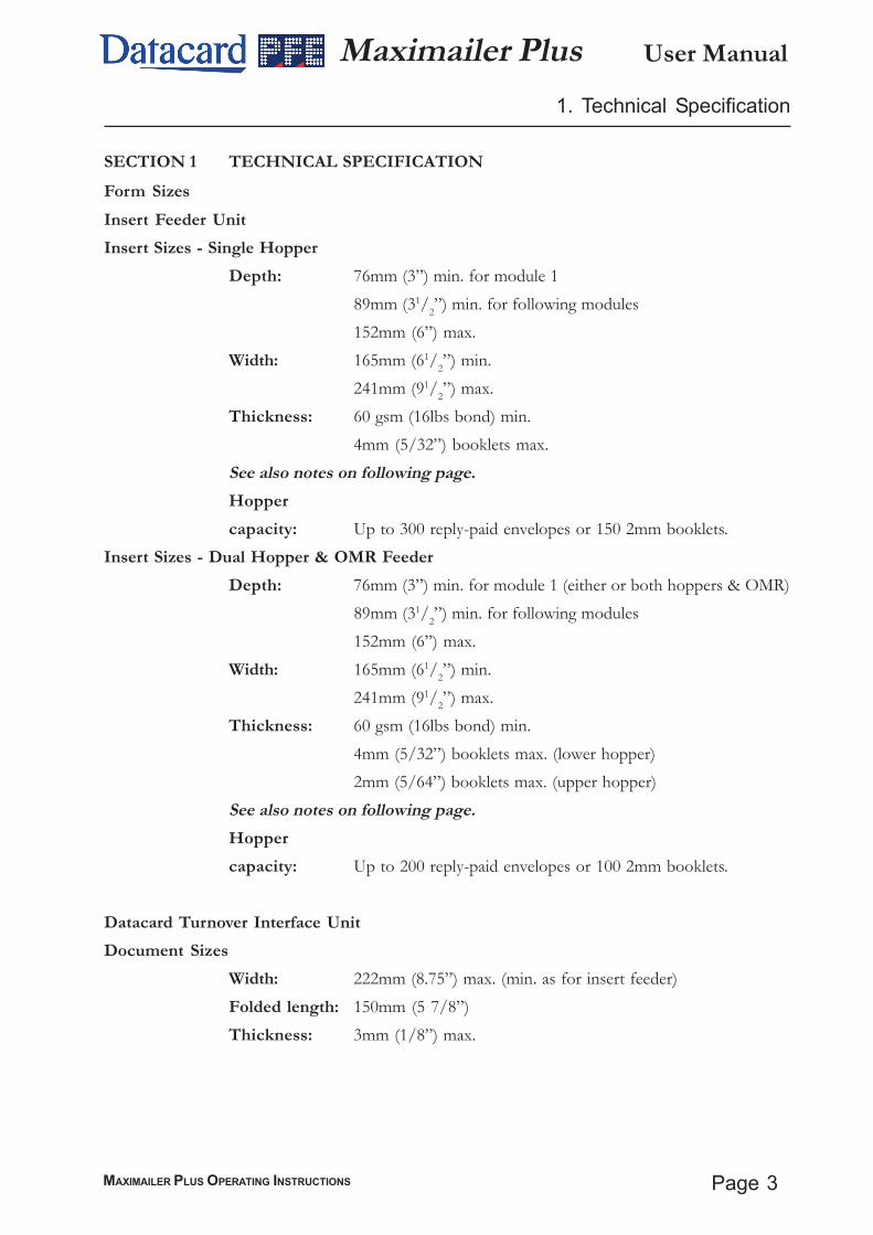
SECTION 1 TECHNICAL SPECIFICATIONForm SizesInsert Feeder UnitInsert Sizes - Single Hopper
Depth: 76mm (3”) min. for module 189mm (31/2”) min. for following modules152mm (6”) max.
Width: 165mm (61/2”) min.241mm (91/2”) max.
Thickness: 60 gsm (16lbs bond) min.4mm (5/32”) booklets max.
See also notes on following page.Hoppercapacity: Up to 300 reply-paid envelopes or 150 2mm booklets.
Insert Sizes - Dual Hopper & OMR FeederDepth: 76mm (3”) min. for module 1 (either or both hoppers & OMR)
89mm (31/2”) min. for following modules152mm (6”) max.
Width: 165mm (61/2”) min.241mm (91/2”) max.
Thickness: 60 gsm (16lbs bond) min.4mm (5/32”) booklets max. (lower hopper)2mm (5/64”) booklets max. (upper hopper)
See also notes on following page.Hoppercapacity: Up to 200 reply-paid envelopes or 100 2mm booklets.
Datacard Turnover Interface UnitDocument Sizes
Width: 222mm (8.75”) max. (min. as for insert feeder)Folded length: 150mm (5 7/8”)Thickness: 3mm (1/8”) max.
1. Technical Specification
User Manual
Page 4 MAXIMAILER PLUS OPERATING INSTRUCTIONS
Maximailer Plus1. Technical Specification (cont.)
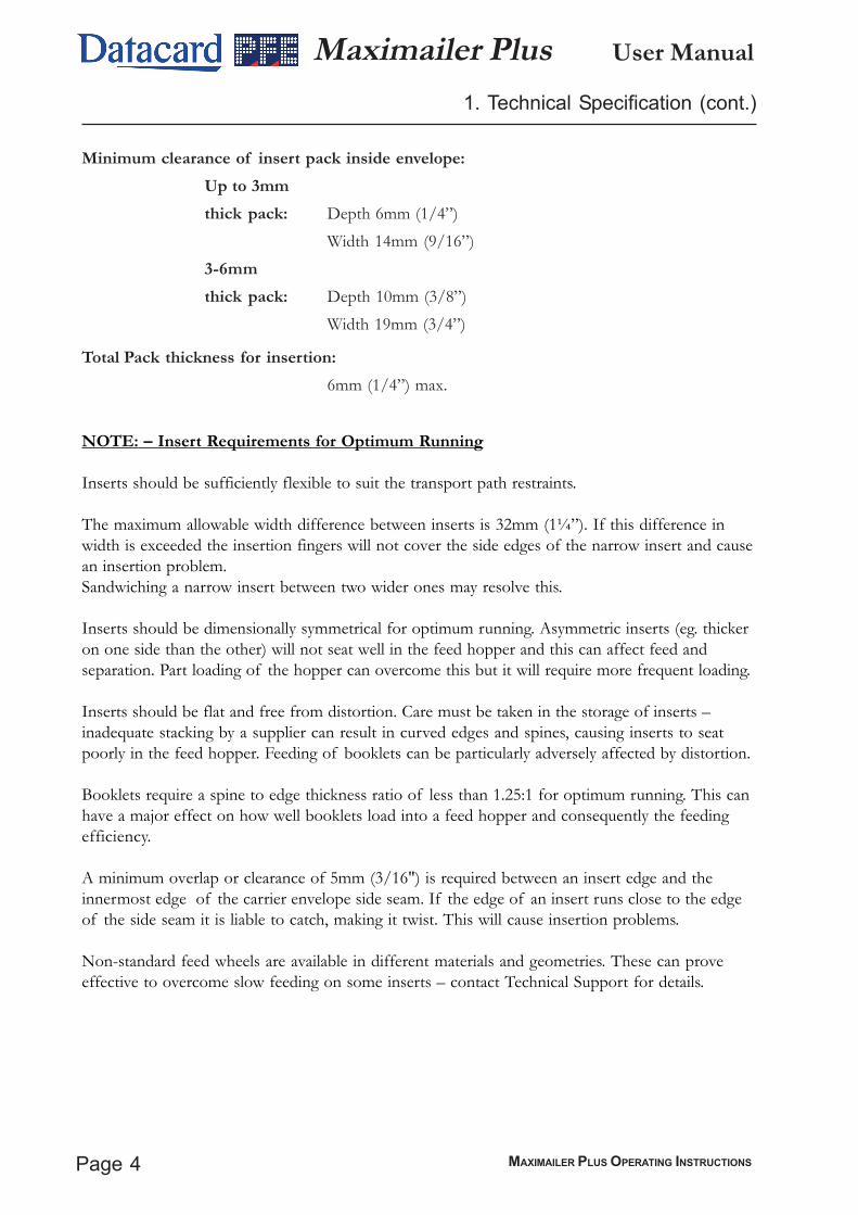
Total Pack thickness for insertion:6mm (1/4”) max.
NOTE: – Insert Requirements for Optimum Running
Inserts should be sufficiently flexible to suit the transport path restraints.
The maximum allowable width difference between inserts is 32mm (1¼”). If this difference inwidth is exceeded the insertion fingers will not cover the side edges of the narrow insert and causean insertion problem.Sandwiching a narrow insert between two wider ones may resolve this.
Inserts should be dimensionally symmetrical for optimum running. Asymmetric inserts (eg. thickeron one side than the other) will not seat well in the feed hopper and this can affect feed andseparation. Part loading of the hopper can overcome this but it will require more frequent loading.
Inserts should be flat and free from distortion. Care must be taken in the storage of inserts –inadequate stacking by a supplier can result in curved edges and spines, causing inserts to seatpoorly in the feed hopper. Feeding of booklets can be particularly adversely affected by distortion.
Booklets require a spine to edge thickness ratio of less than 1.25:1 for optimum running. This canhave a major effect on how well booklets load into a feed hopper and consequently the feedingefficiency.
A minimum overlap or clearance of 5mm (3/16") is required between an insert edge and theinnermost edge of the carrier envelope side seam. If the edge of an insert runs close to the edgeof the side seam it is liable to catch, making it twist. This will cause insertion problems.
Non-standard feed wheels are available in different materials and geometries. These can proveeffective to overcome slow feeding on some inserts – contact Technical Support for details.
Minimum clearance of insert pack inside envelope:Up to 3mmthick pack: Depth 6mm (1/4”)
Width 14mm (9/16”)3-6mmthick pack: Depth 10mm (3/8”)
Width 19mm (3/4”)

Page 5MAXIMAILER PLUS OPERATING INSTRUCTIONS
User ManualMaximailer Plus
Min.10mm(1332")
Max.22mm(78")
Throat Depth
Throat DepthMax.22mm(7
8")Min.10mm(13
32")
Body DepthMax.165mm(61
2")Min. 89mm(31
2")
Envelope Width Max.264mm(1038") Min.178mm(7")
Horizontal portion of throatMax. = Envelope Width - 75mm(3")
Flap Shoulder Angle
Min.70mm (234")
Minimum openthroat area
50°Min. 90°Max.
Min.
(1332")
10mm Throat angle5°Min. 20°Max.
(1332")
Min. 10mm
Max. = Envelope Width - 75mm(3")
Envelope Width Max.264mm(1038") Min.178mm(7")
Min.70mm (234")
Horizontal portion of throat
Flap Shoulder Angle
Minimum openthroat area
Min.50°Min. 90°Max.
(1332")
10mm Throat angle5°Min. 20°Max.
Min. 10mm(13
32")
Flap LengthMax.50mm( 2")Min.32mm(11
4")
Flap LengthMax.50mm( 2")Min.32mm(11
4")
Side Seam style envelope
Commercial style envelope
Body DepthMax.165mm(61
2")Min. 89mm(31
2")
1. Technical Specification (cont.)
Envelope Specification
Envelope Weight: 70gsm (18lbs bond) min., 100gsm (26lbs bond) max.
Hopper Capacity: Up to 400 of 80gsm (20lbs bond) envelopes.
General RequirementsEnvelopes to be good quality machine-fill envelope. Dimensions and quality to beconsistent across manufacture batches.Windows to be securely affixed to within 1.5mm (1/16") of top and side edges. Topedge to be flat and free from puckering.Side seams to be securely glued up to top of seam.Position of internal side seams to give a minimum 5mm (3/16") clearance or overlapto the edge of any insert.Pre-scored flap crease to enable the envelope flap to open flat.No twisting, curling or distortion evident.No glue seepage on interior or exterior of envelope.Paper smoothness: 100-200 Sheffield units.Large printed areas require approval from the Technical Support Dept.Envelopes not meeting the above requirements may be acceptable, subject to testingand approval by Technical Support Dept. Envelopes not meeting the above require-ments may affect machine performance.

User Manual
Page 6 MAXIMAILER PLUS OPERATING INSTRUCTIONS
Maximailer Plus1. Technical Specification (cont.)
General SpecificationSpeed:
Variable up to:
3000 filled envelopes per hour (any fold).
Noise level:Less than 75dbA (3 x feeders, 1 x DTI, measured at 1.6m height, 1m
from nearest cover) - excludes noise level of Card Processor.
Heat Output (BTU/Hour):Rated current x rated volts x 3.412 (eg. 2354 BTU/Hour for typical configura-tion of 3 x feeders + DTI) - excludes heat output of Card Processor.
Heat Output (Watts):Rated current x rated volts (eg. 690W for typical configuration of 3 x feeders +DTI) - excludes heat output of Card Processor.
Electrical:230VAC 115VAC
Frequency 50Hz 60Hz
Input Current Head: 1A Head: 2A
Feeder: 0.5A Feeder: 0.5A
Dual Feeder: 0.5A Dual Feeder: 0.5A
OMR Feeder: 0.5A OMR Feeder: 0.5A
DTI: 0.5A DTI: 0.5A
Fuse Rating T6.3A T10A(Insert Head)
Weights (nett):Inserter Head 56Kg
Feeder 25Kg
Dual Feeder 44Kg
DTI 25Kg

Page 7MAXIMAILER PLUS OPERATING INSTRUCTIONS
User ManualMaximailer Plus2. Machine Layout Guide
2.1 DESCRIPTION OF MACHINE
The function of the Maximailer Plus is to feed forms from a Datacard Card Processor and/or a number of hoppers, fold them in either 'C', 'Z', 'V' or double forward fold (where required)and insert them into an envelope which is then sealed and ejected. The folded card carrier issupplied from the Card Processor via an interface which turns it over before feeding it onto thetrack; the document will then be orientated correctly for the address position. Further inserts(cards, cheques etc.) may optionally be collated with the card carrier by collating on the track. Alldocuments are then gathered in the collation pocket at the inserter head for insertion as one packinto the envelope.
Forms may be inserted without sealing the envelope, eg. for subsequent hand insertion of card,gift etc. Multiple insertions may also be used, ie. a preset number of forms are separately fed ontothe insert track each time the feed unit is called. There is a batch processing facility, allowing apreset number of cycles to be completed before the machine automatically stops.
The machine consists of a number of modules, depending upon the build ordered - thesemodules are briefly described below:
a) Inserter head - Collates all documents in a pocket before insertion, feeds the enve-lope, inserts the pack and seals the flap.
b) Insert Feeder - Feeds shortform inserts (cards, cheques, booklets etc.) onto the trackfor subsequent insertion. Available as a single feeder with one feed hopper or a towerfeeder with two feed hoppers. An OMR/Barcode version (with one feed hopper) isalso available.
c) Datacard Turnover Interface - Receives a folded card carrier from a Card Processor,turns it over to orientate the address correctly and feeds it onto the track for subse-quent insertion.
The Maximailer Plus is equipped with PC controlled operating software from where jobs can beprogrammed and run. Jobs can be quickly switched from the main screen, and can also be ‘fine-tuned’to accommodate a small change in job requirement. The number of jobs that can be programmed islimited only by the capacity of the PC. Input is via touch-screen monitor or keyboard/mouse.
No manual setting of the fold plates or envelope closer is required, these being adjustedautomatically according to the settings in the selected program.

User Manual
Page 8 MAXIMAILER PLUS OPERATING INSTRUCTIONS
Maximailer Plus
2.2 PARTS IDENTIFICATION
Envelopehopper
Insert/collatearea
Output(see below)
PC controlpanel Dual
feeder
Storage cupboards (PCunder insert head)
Note: Station 1 is the firstfeed unit after the insert/collate area.
2. Machine Layout Guide (cont.)
Standardfeeder
Closerarea
Opening sidecovers
DatacardTurnoverInterface
Filled envelopes may be outputinto a receiving tray or onto anoptional conveyor.
Page 9MAXIMAILER PLUS OPERATING INSTRUCTIONS
User ManualMaximailer Plus3. About this Document
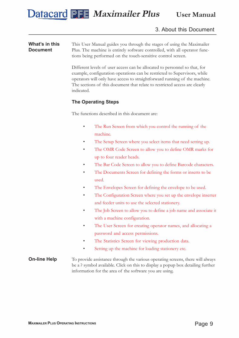
What’s in thisDocument
This User Manual guides you through the stages of using the MaximailerPlus. The machine is entirely software controlled, with all operator func-tions being performed on the touch-sensitive control screen.
Different levels of user access can be allocated to personnel so that, forexample, configuration operations can be restricted to Supervisors, whileoperators will only have access to straightforward running of the machine.The sections of this document that relate to restricted access are clearlyindicated.
The Operating Steps
The functions described in this document are:
• The Run Screen from which you control the running of themachine.
• The Setup Screen where you select items that need setting up.• The OMR Code Screen to allow you to define OMR marks for
up to four reader heads.• The Bar Code Screen to allow you to define Barcode characters.• The Documents Screen for defining the forms or inserts to be
used.• The Envelopes Screen for defining the envelope to be used.• The Configuration Screen where you set up the envelope inserter
and feeder units to use the selected stationery.• The Job Screen to allow you to define a job name and associate it
with a machine configuration.• The User Screen for creating operator names, and allocating a
password and access permissions.• The Statistics Screen for viewing production data.• Setting up the machine for loading stationery etc.
On-line Help To provide assistance through the various operating screens, there will alwaysbe a ? symbol available. Click on this to display a popup box detailing furtherinformation for the area of the software you are using.
User Manual
Page 10 MAXIMAILER PLUS OPERATING INSTRUCTIONS
Maximailer Plus4. The Run Screen
Note: New operators and passwords can be only be entered or edited byauthorised personnel with Supervisor access. This is detailed in section5.5 ‘The Configuration Screen’ on page 27.
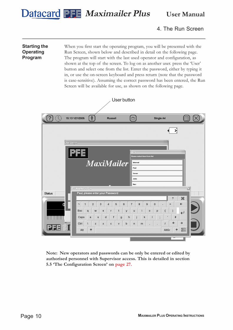
Starting theOperatingProgram
When you first start the operating program, you will be presented with theRun Screen, shown below and described in detail on the following page.The program will start with the last used operator and configuration, asshown at the top of the screen. To log on as another user. press the ‘User’button and select one from the list. Enter the password, either by typing itin, or use the on-screen keyboard and press return (note that the passwordis case-sensitive). Assuming the correct password has been entered, the RunScreen will be available for use, as shown on the following page.
User button
Page 11MAXIMAILER PLUS OPERATING INSTRUCTIONS
User ManualMaximailer Plus4. The Run Screen
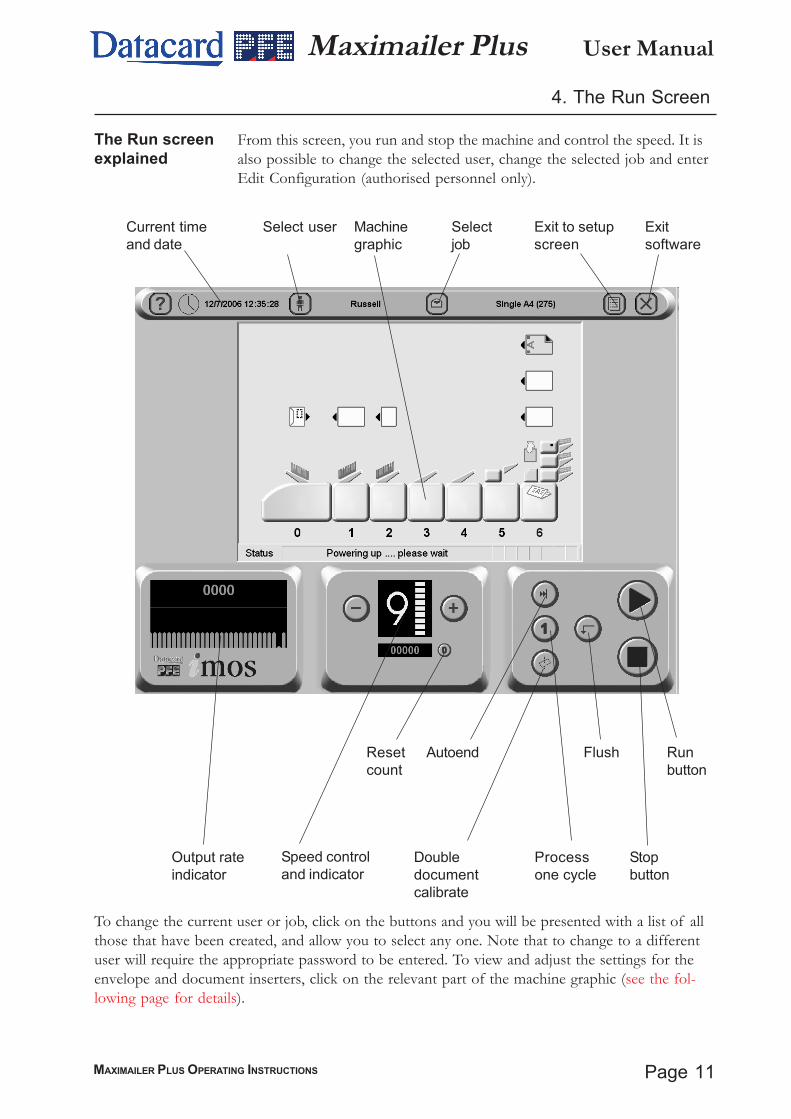
The Run screenexplained
From this screen, you run and stop the machine and control the speed. It isalso possible to change the selected user, change the selected job and enterEdit Configuration (authorised personnel only).
To change the current user or job, click on the buttons and you will be presented with a list of allthose that have been created, and allow you to select any one. Note that to change to a differentuser will require the appropriate password to be entered. To view and adjust the settings for theenvelope and document inserters, click on the relevant part of the machine graphic (see the fol-lowing page for details).
Current timeand date
Select user Selectjob
Exit to setupscreen
Exitsoftware
Output rateindicator
Speed controland indicator
Resetcount
Autoend
Processone cycle
Doubledocumentcalibrate
Runbutton
Stopbutton
Machinegraphic
Flush
User Manual
Page 12 MAXIMAILER PLUS OPERATING INSTRUCTIONS
Maximailer Plus
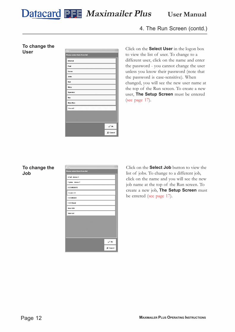
To change theUser
Click on the Select User in the logon boxto view the list of user. To change to adifferent user, click on the name and enterthe password - you cannot change the userunless you know their password (note thatthe password is case-sensitive). Whenchanged, you will see the new user name atthe top of the Run screen. To create a newuser, The Setup Screen must be entered(see page 17).
To change theJob
Click on the Select Job button to view thelist of jobs. To change to a different job,click on the name and you will see the newjob name at the top of the Run screen. Tocreate a new job, The Setup Screen mustbe entered (see page 17).
4. The Run Screen (contd.)

Page 13MAXIMAILER PLUS OPERATING INSTRUCTIONS
User ManualMaximailer Plus4. The Run Screen (contd.)
To adjust the EnvelopeInserter settings
Unit Fine Tuning
Click on the envelope inserteron the machine graphic todisplay the fine tuning screen.Click on Hardware FineTuning to display furtherinformation. You can select:
a: The width of the collatepocket guides.
b: The overall width of theinsert fingers.
c: The time allowed for theflap to seal before the envelopeis ejected.
d: Adjustment of the point at which the wetter beam drops to wet the flap.+ve increases wetting in 1mm steps (moves start point towards insertionarea).
e: Adjustment of the point at which the wetter beam lifts. +ve increasesduration, ie. a greater length of flap is wetted befor the beam is lifted.
f. Adjustment of the amount of envelope travel into the sealing rollers. +ve= further forward, away from exit direction.
g. Adjustment of the envelope stop position for insertion. +ve = furtherforwards, towards exit direction.
h. Adjustment of the amount of insertion of the insert pack into the enve-lope. +ve = further forwards past the flap crease.
i. Adjustment of the amount of envelope foward travel after flap wetting,before reversing to enter the sealing rollers. +ve = further forward into theoutput rollers, towards the exit direction.
When all adjustments are complete, click on the ‘Unit’ button forhopper settings, as described opposite.
Important: All fine adustments apply only to the current job and willnot affect any other jobs.
Note: Click on the ‘Unit’ button in the top left corner totoggle between fine tuning for unit and hopper.

User Manual
Page 14 MAXIMAILER PLUS OPERATING INSTRUCTIONS
Maximailer Plus4. The Run Screen (contd.)
Hopper Fine Tuning
From here you can adjusthopper settings. Click on theinserter hopper, then Docu-ment Fine Tuning to displayfurther information. You canselect:
a: Whether or not the envelopeis sealed. Select ‘Off ’ if, forexample, later hand insertion
of an insert or other item will be required.
b: The setting of the amount of envelope deskew required. Note a higherlevel will slow the machine more.
c: Click on the button and adjust width and depth if actual envelope variesfrom the settings shown.Warning: if the same document is used onother jobs as well, the same settings will be applied.
Important: All fine adustments apply only to the current job and willnot affect any other jobs.
Page 15MAXIMAILER PLUS OPERATING INSTRUCTIONS
User ManualMaximailer Plus4. The Run Screen (contd.)
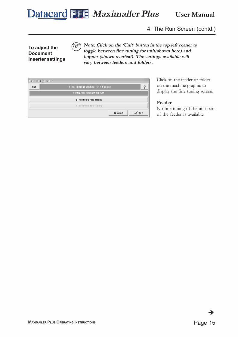
To adjust theDocumentInserter settings
Click on the feeder or folderon the machine graphic todisplay the fine tuning screen.
FeederNo fine tuning of the unit partof the feeder is available
Note: Click on the ‘Unit’ button in the top left corner totoggle between fine tuning for unit(shown here) andhopper (shown overleaf). The settings available willvary between feeders and folders.
User Manual
Page 16 MAXIMAILER PLUS OPERATING INSTRUCTIONS
Maximailer Plus4. The Run Screen (contd.)
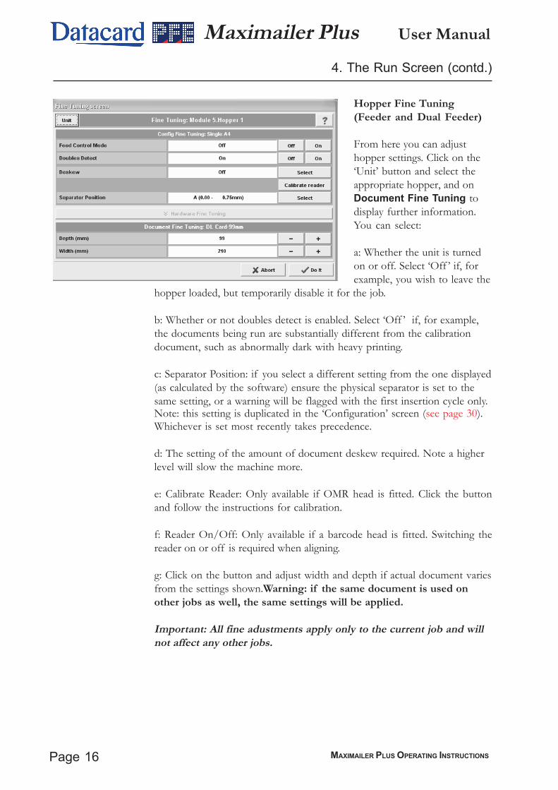
Hopper Fine Tuning(Feeder and Dual Feeder)
From here you can adjusthopper settings. Click on the‘Unit’ button and select theappropriate hopper, and onDocument Fine Tuning todisplay further information.You can select:
a: Whether the unit is turnedon or off. Select ‘Off ’ if, forexample, you wish to leave the
hopper loaded, but temporarily disable it for the job.
b: Whether or not doubles detect is enabled. Select ‘Off ’ if, for example,the documents being run are substantially different from the calibrationdocument, such as abnormally dark with heavy printing.
c: Separator Position: if you select a different setting from the one displayed(as calculated by the software) ensure the physical separator is set to thesame setting, or a warning will be flagged with the first insertion cycle only.Note: this setting is duplicated in the ‘Configuration’ screen (see page 30).Whichever is set most recently takes precedence.
d: The setting of the amount of document deskew required. Note a higherlevel will slow the machine more.
e: Calibrate Reader: Only available if OMR head is fitted. Click the buttonand follow the instructions for calibration.
f: Reader On/Off: Only available if a barcode head is fitted. Switching thereader on or off is required when aligning.
g: Click on the button and adjust width and depth if actual document variesfrom the settings shown.Warning: if the same document is used onother jobs as well, the same settings will be applied.
Important: All fine adustments apply only to the current job and willnot affect any other jobs.

Page 17MAXIMAILER PLUS OPERATING INSTRUCTIONS
User ManualMaximailer Plus5. The Setup Screen
The Setupscreen ex-plained
From this screen, you make changes to the machine setup. Changes canthen be saved and will remain until they are changed again. To enter thescreen, click the setup button on the Run screen.
OMR Code
Bar Code
Documents
Envelopes
Configuration
Job
Users
Statistics
Engineering
Admin
Run Screen
Allows OMR mark settings to be created, viewed or altered.
Allows Bar Code settings to be created, viewed or altered.
Allows form and insert settings to be defined or altered.
Allows envelope settings to be defined or altered.
Configure the machine for all settings to use with the selected stationery.
Create a new job, or alter an existing one.
Allows a new user to be added, and a password and permissions to be set.These can be also be altered for existing operators.
Displays information on current machine settings, production run data etc.
Allows testing of various parts of the machine. Only available to personnelwith engineer access, and described in detail in the Automailer 5 Service Manual.
Allows administration of various machine functions.
Click on this to take you back to the Run Screen.

User Manual
Page 18 MAXIMAILER PLUS OPERATING INSTRUCTIONS
Maximailer Plus5. The Setup Screen (contd.)
Click on any of the buttons onthe Setup screen to display a listbox. Shown left is the list boxfor the Document, and is similarfor all of the buttons on theSetup screen. The list boxshows all of the setups thathave been defined so far. Selectany of the setups shown andthis can then be edited, copiedor deleted by clicking on theappropriate button at the bot-tom of the box. New setups canalso be created by clicking onthe New button, and the newlycreated item can then be editedas required. Note that eachname is allocated an ID numberby the software, this beingappended to the name. You cansort the list by ID or name, and
if the list is long and a scroll bar appears, you can also search the list by name or ID using thebuttons at the bottom. A filter can also be applied, to list only names or IDs containing criteria,such as a keyword or a part of it.
When either the New or Edit buttons are clicked, the edit screen for that particular setup is dis-played. These are explained in detail on the page indicated below:
List BoxOMR Code: Page 19Bar Code: Page 21Documents: Page 23Envelopes: Page 25Configuration: Page 27Job: Page 35Users: Page 36
If any changes are made to the list box (ie. if an existing item is copied or deleted), the Save buttonwill be active. Click on this to save the changes, and click Exit. Note that if an item is edited, anychanges will be saved on that particular edit screen, and the Save button will remain dimmed.
Warning!!For the ‘OMR Code’, ‘Bar Code’, ‘Documents’ and ‘Envelopes’ list boxes, do not delete asetup that is currently used in any configuration. If you do, the configuration that uses thesetup will be substituted with the factory configuration named ‘Default Config’, whichcannot be deleted or edited (for further details of Configurations, see page 27).
The List Box
Page 19MAXIMAILER PLUS OPERATING INSTRUCTIONS
User ManualMaximailer Plus5.1 The OMR Code Screen
Editing thesetup name.
Editing thesettings.
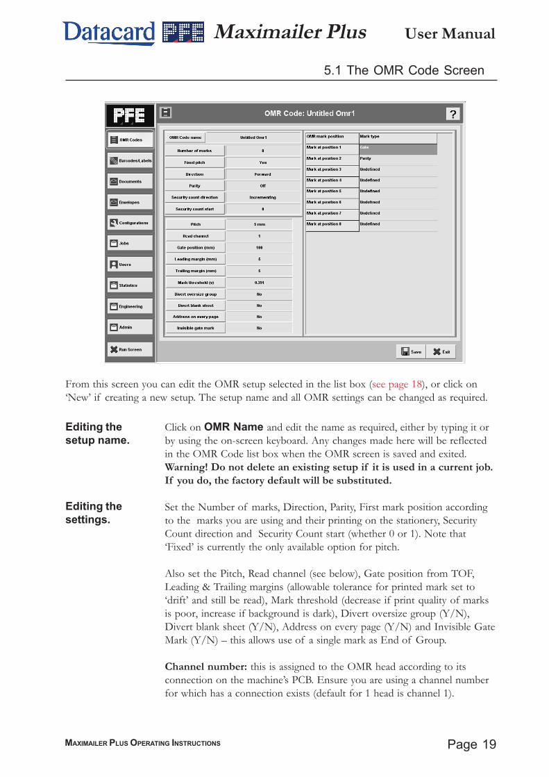
Click on OMR Name and edit the name as required, either by typing it orby using the on-screen keyboard. Any changes made here will be reflectedin the OMR Code list box when the OMR screen is saved and exited.Warning! Do not delete an existing setup if it is used in a current job.If you do, the factory default will be substituted.
Set the Number of marks, Direction, Parity, First mark position accordingto the marks you are using and their printing on the stationery, SecurityCount direction and Security Count start (whether 0 or 1). Note that‘Fixed’ is currently the only available option for pitch.
Also set the Pitch, Read channel (see below), Gate position from TOF,Leading & Trailing margins (allowable tolerance for printed mark set to‘drift’ and still be read), Mark threshold (decrease if print quality of marksis poor, increase if background is dark), Divert oversize group (Y/N),Divert blank sheet (Y/N), Address on every page (Y/N) and Invisible GateMark (Y/N) – this allows use of a single mark as End of Group.
Channel number: this is assigned to the OMR head according to itsconnection on the machine’s PCB. Ensure you are using a channel numberfor which has a connection exists (default for 1 head is channel 1).
From this screen you can edit the OMR setup selected in the list box (see page 18), or click on‘New’ if creating a new setup. The setup name and all OMR settings can be changed as required.

User Manual
Page 20 MAXIMAILER PLUS OPERATING INSTRUCTIONS
Maximailer Plus
Now click on each OMR mark position button and enter the type of mark for each position,according to the marks you are using.
Note: Prior to running a new or edited OMR setup, the machine must first be calibratedusing a calibration sheet (see note below). The results of the calibration will be shown on thescreen for each selected OMR unit.
After making any changes, click the Save button at the bottom of the screen, and then the Exitbutton to return to the list box.
Note: For full details of OMR specifications and calibration, see PFE document ‘Specificationsfor Maximailer Plus’.
5.1 The OMR Code Screen (cont.)
Page 21MAXIMAILER PLUS OPERATING INSTRUCTIONS
User ManualMaximailer Plus
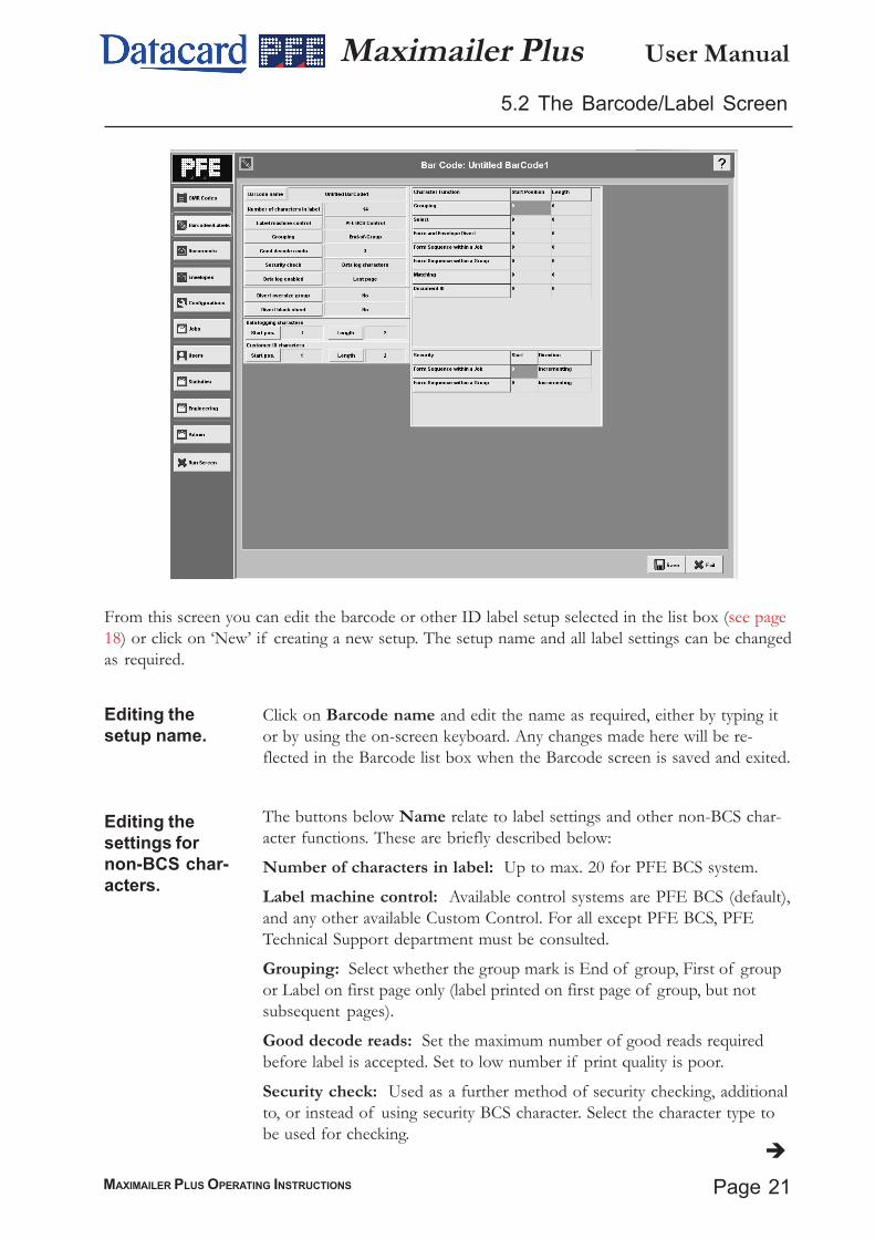
Click on Barcode name and edit the name as required, either by typing itor by using the on-screen keyboard. Any changes made here will be re-flected in the Barcode list box when the Barcode screen is saved and exited.
The buttons below Name relate to label settings and other non-BCS char-acter functions. These are briefly described below:
Number of characters in label: Up to max. 20 for PFE BCS system.
Label machine control: Available control systems are PFE BCS (default),and any other available Custom Control. For all except PFE BCS, PFETechnical Support department must be consulted.
Grouping: Select whether the group mark is End of group, First of groupor Label on first page only (label printed on first page of group, but notsubsequent pages).
Good decode reads: Set the maximum number of good reads requiredbefore label is accepted. Set to low number if print quality is poor.
Security check: Used as a further method of security checking, additionalto, or instead of using security BCS character. Select the character type tobe used for checking.
Editing thesetup name.
Editing thesettings fornon-BCS char-acters.
From this screen you can edit the barcode or other ID label setup selected in the list box (see page18) or click on ‘New’ if creating a new setup. The setup name and all label settings can be changedas required.
5.2 The Barcode/Label Screen

User Manual
Page 22 MAXIMAILER PLUS OPERATING INSTRUCTIONS
Maximailer Plus
Editing thesettings forBCS characters.
5.2 The Barcode/Label Screen (contd.)
Data log enabled: If selected, a record of the movements of each groupwill be retained in a log file which can be viewed later in the Statisticsscreen. This data can then be used to compare the original number ofdocuments with the number of processed envelopes. Choose whether to logfrom the label on the first page of a group, or the last. For details of DataLogging and the Statistics screen, see page 37.Divert oversize group: If set to ‘Yes’, groups that are too large to foldwill be fed into the divert tray (if fitted) without stopping the machine. Ifno tray is fitted, the machine will stop with the group in the accumulator.
Divert blank sheet: As above, but applying to sheets with no label.
Data logging characters: If data logging is being used, click on and enterthe start character position and number of characters. See also page 37.Customer ID characters: Customer ID can be used for grouping, as analternative to the Grouping character. Each form within a group is printedwith the same character(s), with each group using a different character(s).
Click on and enter the start position and character length of each function,either by typing it in the ‘Enter Value’ box, or by using the on-screenkeypad. Number 1 is the first mark from the leading edge. ‘0’ (zero) meansthat character is not used. Note: a minimum of 4 characters must be used.See also ‘Barcode Specification for Maximailer Plus’.
Form sequence within a Job: This is used to ensure that forms areprocessed through the inserter in the same order that they were printed, andthat there are no missing forms. This is achieved by coding each form as itis printed with the alphabetic characters A,B,C......Z. The sequence thenrestarts at A again. When the forms are read by the barcode reader anydeviation from the correct order is detected and an error produced.
Set the start character position, and whether Incrementing (A - Z), ordecrementing (Z - A).
Form sequence within a Group: As above, but A,B,C.....Z are printed oneach form within the group, then repeated for the next group. Note: if bothJob and Group security are used, Direction must the same for each.
After making any changes, click the Save button at the bottom of thescreen, and then the Exit button to return to the list box.
Security

Page 23MAXIMAILER PLUS OPERATING INSTRUCTIONS
User ManualMaximailer Plus
Editing thesetup name.
Editing thesettings.
Click on Name and edit the name as required, either by typing it or byusing the on-screen keyboard. Any changes made here will be reflected inthe Documents list box when the above screen is saved and exited.
Warning! Do not edit the name for a Document currently used in anyconfiguration. If you do, the factory default document ‘A4’ will be usedinstead.Icon: Select the icon from a preset list - this icon that will then appear in thegraphic on the Configuration screen (see page 27).
Form type: Select the form type from a preset list. Select ‘Card Carrier’ forall documents from a Card Processor.
Width/Depth/Paper Weight: Click on the appropriate button and enterthe required setting for the form or insert width, depth and weight (in theunits shown) - see also Thickness & True Weight on the following page.Note: width and depth apply to finished (ie. folded) card carrier.
Thickness: If the insert is a booklet or other thick material, click the ‘Com-puted’ button to uncheck the box, and then click the ‘Thickness’ button.Enter the required figure in mm. Note that if this function is used PaperWeight will not be active.
From this screen you can edit the Form/Insert setup that was selected in the list box (see page 18)or click on ‘New’ if creating a new setup. The setup name and all form or insert parameters can bechanged as required.
5.3 The Documents Screen

User Manual
Page 24 MAXIMAILER PLUS OPERATING INSTRUCTIONS
Maximailer Plus5.3 The Documents Screen (contd.)
True Weight: This shows the weight of the document or insert in the unitsshown, and is linked to Thickness above. To enter a known weight, clickthe ‘Computed’ button to uncheck the box, and then click the ‘True Weight’button. Enter the required figure in the units shown. Note that if thisfunction is used Paper Weight will not be active. The true weight needonly be entered if Postage Rates are being used (see page 33).
Pre-Folded Leaves: If the insert consists of more than one leaf (eg. a ‘Z’folded flyer), click the button and enter the number of leaves.
OMR Name: Click this button if you are using OMR, then click theName button and select an OMR setup (see page 19 for defining OMRsetups).
Label Name: Click this button if you are using barcodes or other labels,then click the Name button and select a label setup (see page 21 for defin-ing barcode setups).
Document ID: Used to verify that the correct stationery is loaded into thecorrect feed unit. If using this feature, set ‘Doc ID Mode’ to ON and definethe alpha-numeric characters being used for the ID. Note that the startposition and length of the characters must be set in the Barcode/Labelscreen. See also ‘Barcode Specification for Maximailer Plus’ for a full de-scription of Document ID.
Document Address: If this is the address document, click the ‘AddressPosition’ button and select the position that best describes the location ofthe address - this will be used by the software to determine the type of foldand orientation of stationery. Note that the left/right location of the ad-dress is not stated, as this will be determined by the printed address match-ing the lateral position of the envelope window. If it is not the addressdocument, click ‘None’.
Click the ‘Save as Default’ button if you wish this to be the setup that newdocuments will default to.
When all editing is complete, click the Save button at the bottom of thescreen, and then the Exit button to return to the list box.
Editing thesettings (contd.)
Notes:1. Minimum document width in the pack (including inserts) must be no smallerthan the maximum document width by more than the following: Minimum docu-ment width = (Maximum document width/2) + 58mm. eg. if maximum document =210mm, minimum document width = (210/2) + 58 = 163mm minimum.

Page 25MAXIMAILER PLUS OPERATING INSTRUCTIONS
User ManualMaximailer Plus5.4 The Envelopes Screen
Editing thesetup name.
Editing thesettings.
From this screen you can edit the Envelope setup that was selected in the list box (see page 18) orclick on ‘New’ if creating a new setup. The setup name and all envelope parameters can be changedas required.
Click on Name and edit the name as required, either by typing it or by usingthe on-screen keyboard. Any changes made here will be reflected in theDocuments list box when the Documents screen is saved and exited.Warning! Do not edit the name for an Envelope currently used in anyconfiguration. If you do, the factory default document ‘DL’ will beused instead.
Icon: Select the icon from a preset list - this icon that will then appear in thegraphic on the Configuration screen (see page 27).
Width/Depth/Paper Weight/Flap: Click on the appropriate button andenter the required setting for the envelope’s width, depth, weight (in the unitsshown) and flap length - see also Thickness below.
Thickness: If the envelope is of very thick material or of unknown weight,click the ‘Computed’ button to uncheck the box, and then click the ‘Thick-ness’ button. Enter the required figure in mm. Note that if this function isused Paper Weight above will not be active.

User Manual
Page 26 MAXIMAILER PLUS OPERATING INSTRUCTIONS
Maximailer Plus
True Weight: This shows the weight of the envelope in the units shown,and is linked to Thickness described on the previous page. To enter aknown weight, click the ‘Computed’ button to uncheck the box, and thenclick the ‘True Weight’ button. Enter the required figure in the units shown.Note that if this function is used Paper Weight will not be active. The trueweight need only be entered if Postage Rates are being used (see page 33).
Amount of wetting required: Different envelope types may require agreater or lesser amount of wetting for an effective seal. If you wish tochange from the default setting of 3, click the appropriate button wheresetting 1 is the least, 4 is the greatest.
OMR Name: This function is not available for envelopes.
Label Name: Click this button if you are using barcodes or other labels forverification checking at output, then click the Name button and select a labelsetup (see page 21 for defining barcode setups). Note that the label can beprinted either on the document (for reading through the window), or on theenvelope.
Click the ‘Save as Default’ button if you wish this tp be the setup that newdocuments will default to.
When all editing is complete, click the Save button at the bottom of thescreen, and then the Exit button to return to the list box.
5.4 The Envelopes Screen (contd.)
Editing thesettings (contd.)
Page 27MAXIMAILER PLUS OPERATING INSTRUCTIONS
User ManualMaximailer Plus5.5 The Configuration Screen
Configuring theinserter.
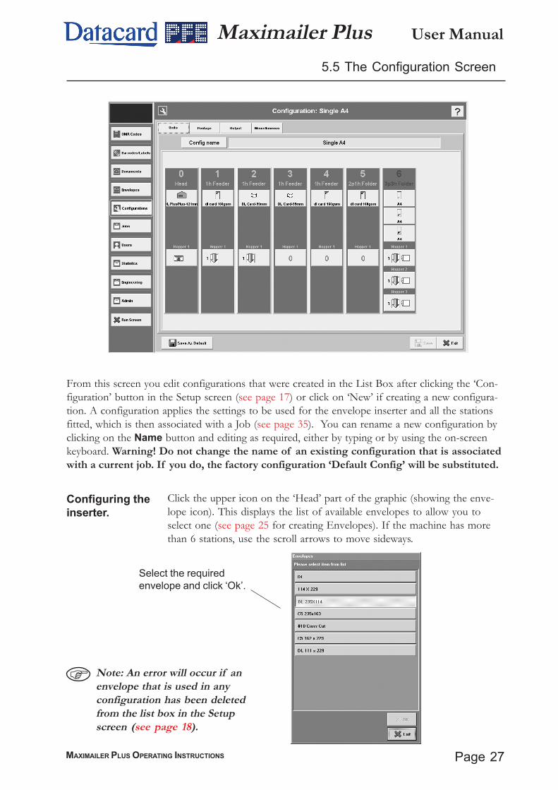
Click the upper icon on the ‘Head’ part of the graphic (showing the enve-lope icon). This displays the list of available envelopes to allow you toselect one (see page 25 for creating Envelopes). If the machine has morethan 6 stations, use the scroll arrows to move sideways.
From this screen you edit configurations that were created in the List Box after clicking the ‘Con-figuration’ button in the Setup screen (see page 17) or click on ‘New’ if creating a new configura-tion. A configuration applies the settings to be used for the envelope inserter and all the stationsfitted, which is then associated with a Job (see page 35). You can rename a new configuration byclicking on the Name button and editing as required, either by typing or by using the on-screenkeyboard. Warning! Do not change the name of an existing configuration that is associatedwith a current job. If you do, the factory configuration ‘Default Config’ will be substituted.
Select the requiredenvelope and click ‘Ok’.
Note: An error will occur if anenvelope that is used in anyconfiguration has been deletedfrom the list box in the Setupscreen (see page 18).

User Manual
Page 28 MAXIMAILER PLUS OPERATING INSTRUCTIONS
Maximailer Plus5.5 The Configuration Screen (contd.)
Setting theinserter optionsfor the Inserterunit
Click on the bottom section of the Inserter (showing the unit icon), and thefollowing dialog box appears:
Seal Mode: Options are Off / Always / Unseal OMR Select /Off Flap Open (if ‘Off ’ is selected, flap is closed without sealing).
Deskew: The setting of the amount of envelope deskewrequired. Note a higher level will slow the machine more.
Item ID: If available for setting. must be set to Item ID 1.
Select ‘Save asDefault’ to make
this the default for allnew setups. Thesesettings then apply to‘Load Default’
Page 29MAXIMAILER PLUS OPERATING INSTRUCTIONS
User ManualMaximailer Plus
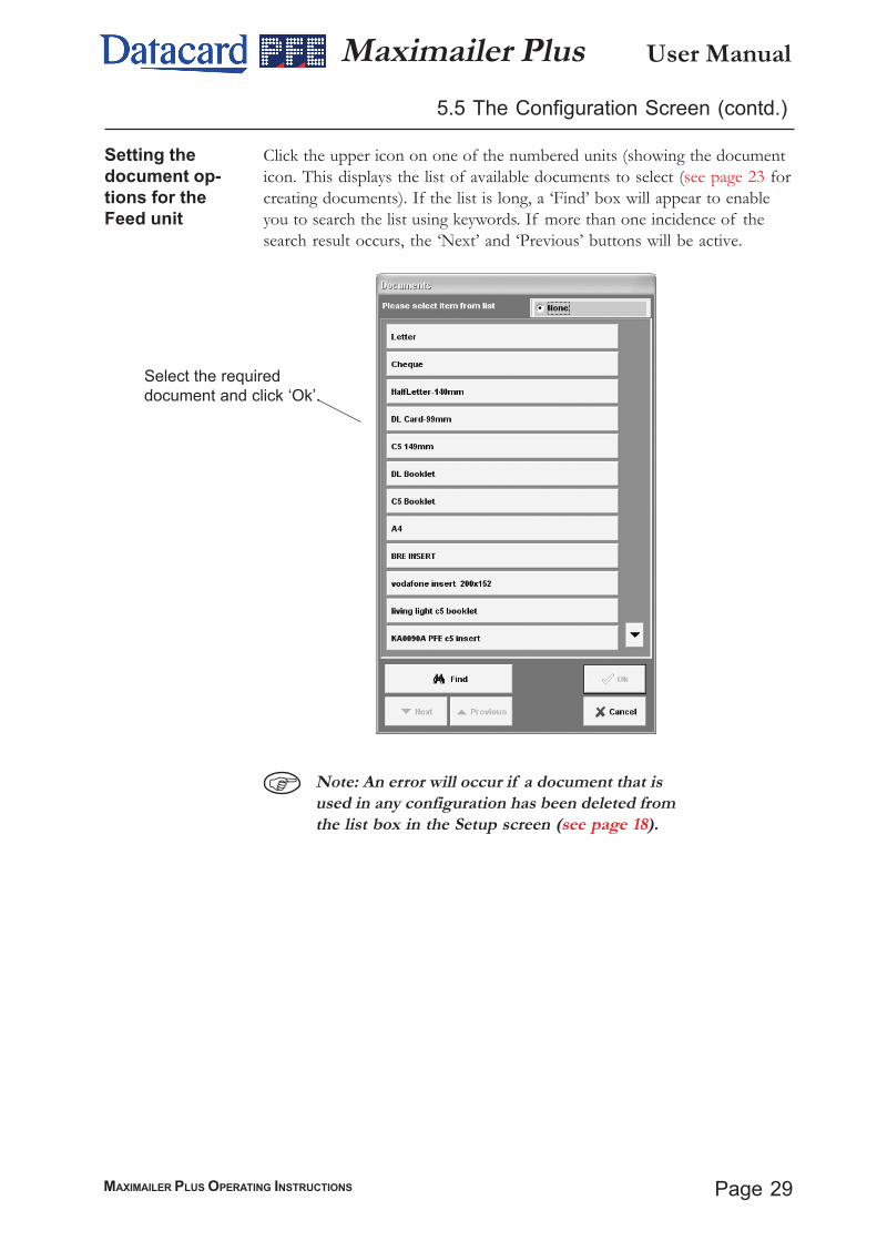
Setting thedocument op-tions for theFeed unit
Click the upper icon on one of the numbered units (showing the documenticon. This displays the list of available documents to select (see page 23 forcreating documents). If the list is long, a ‘Find’ box will appear to enableyou to search the list using keywords. If more than one incidence of thesearch result occurs, the ‘Next’ and ‘Previous’ buttons will be active.
5.5 The Configuration Screen (contd.)
Select the requireddocument and click ‘Ok’.
Note: An error will occur if a document that isused in any configuration has been deleted fromthe list box in the Setup screen (see page 18).

User Manual
Page 30 MAXIMAILER PLUS OPERATING INSTRUCTIONS
Maximailer Plus5.5 The Configuration Screen (contd.)
Setting the feedoptions for theFeed unit
Click on the lower icon of the numbered feed unit (showing the unit icon),and the following dialog box appears:
Address Carrier: Select whether or not this is the address document.Note: this can also be selected from ‘Miscellaneous’ (see page 35). Which-ever is set the later takes precedence.
Feed Control Mode: Options are: Off / Feed Always / OMR orBarcode Select (the latter only available if unit is OMR/Barcode enabled).
Fold Mode: (3-plate folder only) Options are: Singly / Together/ Via accumulator (the latter is only available if the unit has an accumula-tor fitted: if so, forms will group in accumulator first before folding.only).
Form Count: Only available if ‘Mark reading’ is Off. If multipleforms are required, set this to the required quantity. Note: ensure that themaximum fold capacity is not exceeded.
Mark Reading: Only available if unit is OMR/Barcode and amarked document is selected. Options are: Off / OMR marks / Barcodelabels / 2D Datamatrix / OCR.
Thickness Doubles: Set to ‘Off ’ if, for example, the documents beingrun are substantially different from the calibration document, such asabnormally dark with heavy printing.
Deskew: Set the amount of envelope deskew required. Note a higherlevel will slow the machine more.
Item ID: Options are: Auto / Nos. 2 - 17. Use ‘Auto’ unless select feedmarks are being read; ‘Item ID’ then allows a number to be assigned to eachunit to identify with the select feed mark.
Note that theoptions in the dialogbox may vary fromthose shown, de-pending on whetherthe unit is a feederor a folder.
Select ‘Save asDefault’ to make
this the default for allnew setups. Thesesettings then apply to‘Load Default’
Page 31MAXIMAILER PLUS OPERATING INSTRUCTIONS
User ManualMaximailer Plus5.5 The Configuration Screen (contd.)
Default Separator Position: Only available on feeder or dual feeder andis a read-only display. Indicates the separator position calculated by thesoftware. If the physical separator is set differently from this, a warning willbe flagged for the first insertion cycle only.
Separator Position: Only available on feeder or dual feeder. If youselect a different setting from the one displayed in ‘Default SeparatorPosition’ (see above) ensure the physical separator is set to the same setting,or a warning will be flagged with the first insertion cycle only. Note: thissetting is duplicated in the ‘Fine Tuning’ screen (see page 16). Whichever isset most recently takes precedence.
Cascading: Feeds from previous or next unit if feeder runs out ofinserts. Settings available will depend upon hardware fitted and location ofhopper. ‘Above’ and ‘Below’ apply to multi-hopper units. ‘Left’ and ‘Right’apply to single-hopper units as viewed from the operator standpoint.
User Manual
Page 32 MAXIMAILER PLUS OPERATING INSTRUCTIONS
Maximailer Plus
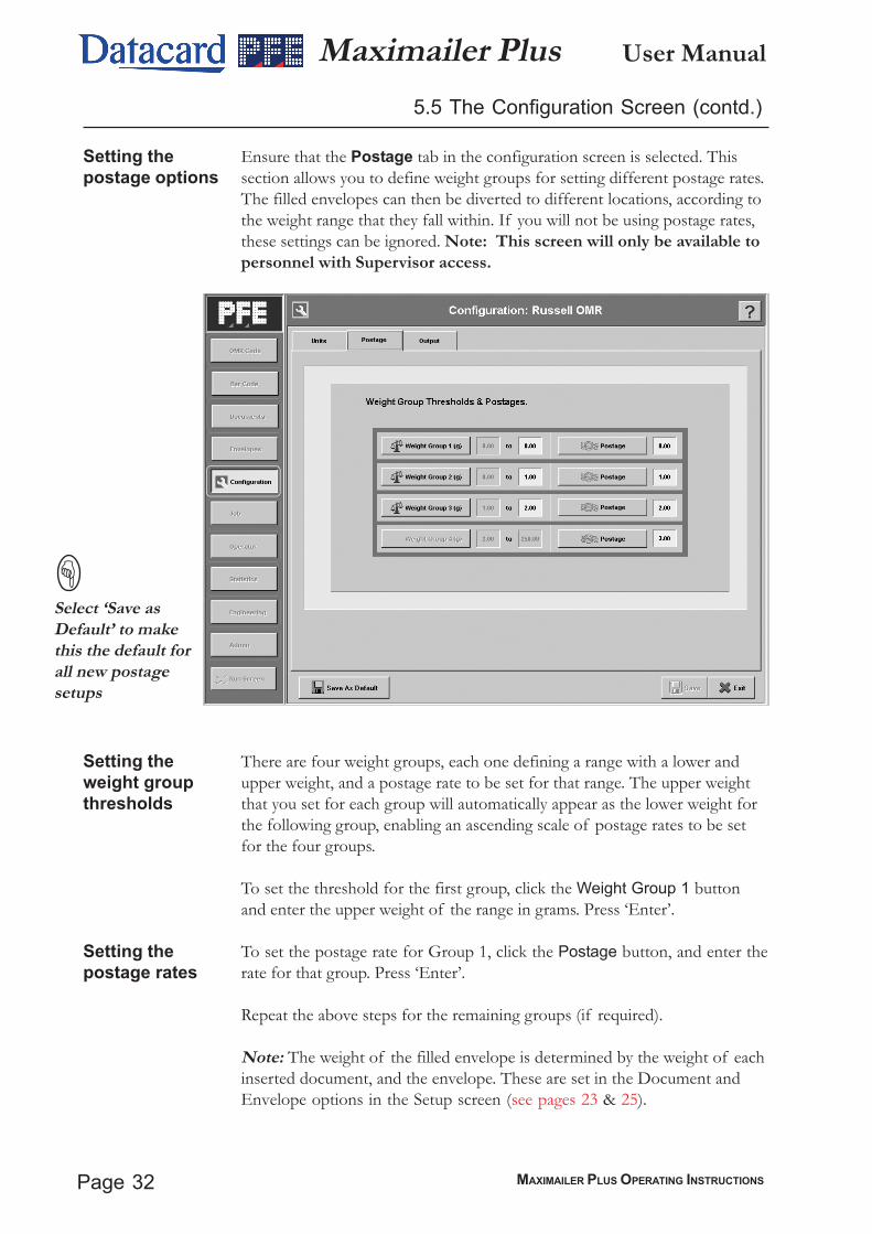
Setting thepostage options
5.5 The Configuration Screen (contd.)
Ensure that the Postage tab in the configuration screen is selected. Thissection allows you to define weight groups for setting different postage rates.The filled envelopes can then be diverted to different locations, according tothe weight range that they fall within. If you will not be using postage rates,these settings can be ignored. Note: This screen will only be available topersonnel with Supervisor access.
Setting theweight groupthresholds
Setting thepostage rates
There are four weight groups, each one defining a range with a lower andupper weight, and a postage rate to be set for that range. The upper weightthat you set for each group will automatically appear as the lower weight forthe following group, enabling an ascending scale of postage rates to be setfor the four groups.
To set the threshold for the first group, click the Weight Group 1 buttonand enter the upper weight of the range in grams. Press ‘Enter’.
To set the postage rate for Group 1, click the Postage button, and enter therate for that group. Press ‘Enter’.
Repeat the above steps for the remaining groups (if required).
Note: The weight of the filled envelope is determined by the weight of eachinserted document, and the envelope. These are set in the Document andEnvelope options in the Setup screen (see pages 23 & 25).
Select ‘Save asDefault’ to makethis the default forall new postagesetups
Page 33MAXIMAILER PLUS OPERATING INSTRUCTIONS
User ManualMaximailer Plus
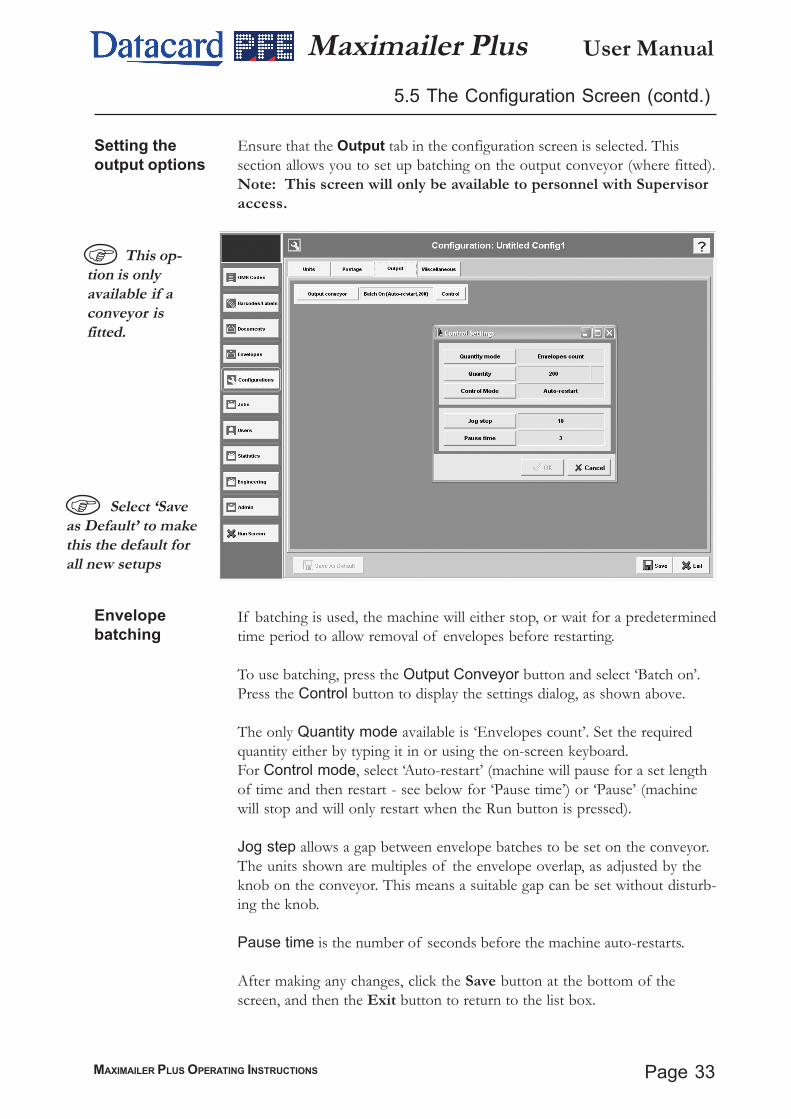
Setting theoutput options
Ensure that the Output tab in the configuration screen is selected. Thissection allows you to set up batching on the output conveyor (where fitted).Note: This screen will only be available to personnel with Supervisoraccess.
5.5 The Configuration Screen (contd.)
Envelopebatching
This op-tion is onlyavailable if aconveyor isfitted.
Select ‘Saveas Default’ to makethis the default forall new setups
If batching is used, the machine will either stop, or wait for a predeterminedtime period to allow removal of envelopes before restarting.
To use batching, press the Output Conveyor button and select ‘Batch on’.Press the Control button to display the settings dialog, as shown above.
The only Quantity mode available is ‘Envelopes count’. Set the requiredquantity either by typing it in or using the on-screen keyboard.For Control mode, select ‘Auto-restart’ (machine will pause for a set lengthof time and then restart - see below for ‘Pause time’) or ‘Pause’ (machinewill stop and will only restart when the Run button is pressed).
Jog step allows a gap between envelope batches to be set on the conveyor.The units shown are multiples of the envelope overlap, as adjusted by theknob on the conveyor. This means a suitable gap can be set without disturb-ing the knob.
Pause time is the number of seconds before the machine auto-restarts.
After making any changes, click the Save button at the bottom of thescreen, and then the Exit button to return to the list box.

User Manual
Page 34 MAXIMAILER PLUS OPERATING INSTRUCTIONS
Maximailer Plus5.5 The Configuration Screen (contd.)
Setting themiscellaneousoptions
Ensure that the Miscellaneous tab in the configuration screen is selected.This section allows you to select the required station for data logging(where used), and also for the address carrying document. Note: Thisscreen will only be available to personnel with Supervisor access.
Setting thedatalog unit
Address Carrier
Confirmcalibration
If you are using datalogs, set the unit you wish to use to record the log fromby pressing ‘Logging from’. By default, this will be the prime unit. See page39 for further details of datalogs.
This allows you to select the unit that carries the address document (usuallythe prime unit). Note: this can also be selected from ‘Feed options for feedunit’ (see page 30). Whichever is set the later takes precedence.
Select ‘No’ if you wish the machine to continue running after a calibrationcycle is performed (by defaut, machine will stop and await confirmation ofenvelope contents.
After making any changes, click the Save button at the bottom of the screen,and then the Exit button to return to the list box.

Page 35MAXIMAILER PLUS OPERATING INSTRUCTIONS
User ManualMaximailer Plus5.6 The Job Screen
Editing the jobname.
Selecting aconfiguration.
Logging OCRdata
Late divert
Checking
Click on Job Name and edit the job name as required, either by typing it orby using the on-screen keyboard. Any changes made here will be reflectedin the Job list box when the Job screen is saved and exited.
Click on Configuration and select an existing one from the list, if any. Tocreate a new configuration, see ‘The Configuration Screen’ on page 27.
Note: A configuration can be associated with as many jobs as you wish.Click on Log OCR data if you are using an OCR scanner on the outputand need to log the data gathered. Select ‘On (CommPort)’ if you wish tolog data via the PC port. Select ‘Display verification read’ to display data onthe Run screen as well as log to file. The file will be stored in theData\DataLogs directory on the hard disk, and will take the formatocr_<Jobname>_<Date>.txt (‘ocr’ will vary for different data types).
Set this to ‘Yes’ to use customer’s own data file to divert using the ID fieldlabel instead of the Divert BCS Character. Set to ‘On’ to divert for this jobonly, or set to ‘All’ to divert on occurrence of label in any job. Note that theDivert BCS character can also be used in conjunction with ID field label.
Not currently used.
From this screen you can edit the job that was selected in the list box (see page 18), or click on‘New’ if creating a new job. The job name can be changed and/or a different configuration associ-ated with it.

User Manual
Page 36 MAXIMAILER PLUS OPERATING INSTRUCTIONS
Maximailer Plus5.7 The Users Screen
Editing thepassword.
Editing the username.
Setting theroles
Click on Password and edit the password as required, either by typing it orby using the on-screen keyboard. This is the password that must be enteredwhen the user is selected from the Run screen. Note: the password is case-sensitive
Click on User name and edit the name as required, either by typing it or byusing the on-screen keyboard. Any changes made here will be reflected inthe User list box when the Users screen is saved and exited.
Check the boxes as required to set the roles (access levels) that are to beallocated the user. To provide access to all roles, select ‘Superuser’.
For further explanation of the roles, contact PFE Technical Support.
After making any changes, click the Save button at the bottom of thescreen, and then the Exit button to return to the list box.
Note: This screen will only be available to personnel with Supervisor access.
From this screen you can edit the user that was selected in the list box (see page 18), or click on‘New’ if creating a new user. The user name, password and access levels can be changed.
Page 37MAXIMAILER PLUS OPERATING INSTRUCTIONS
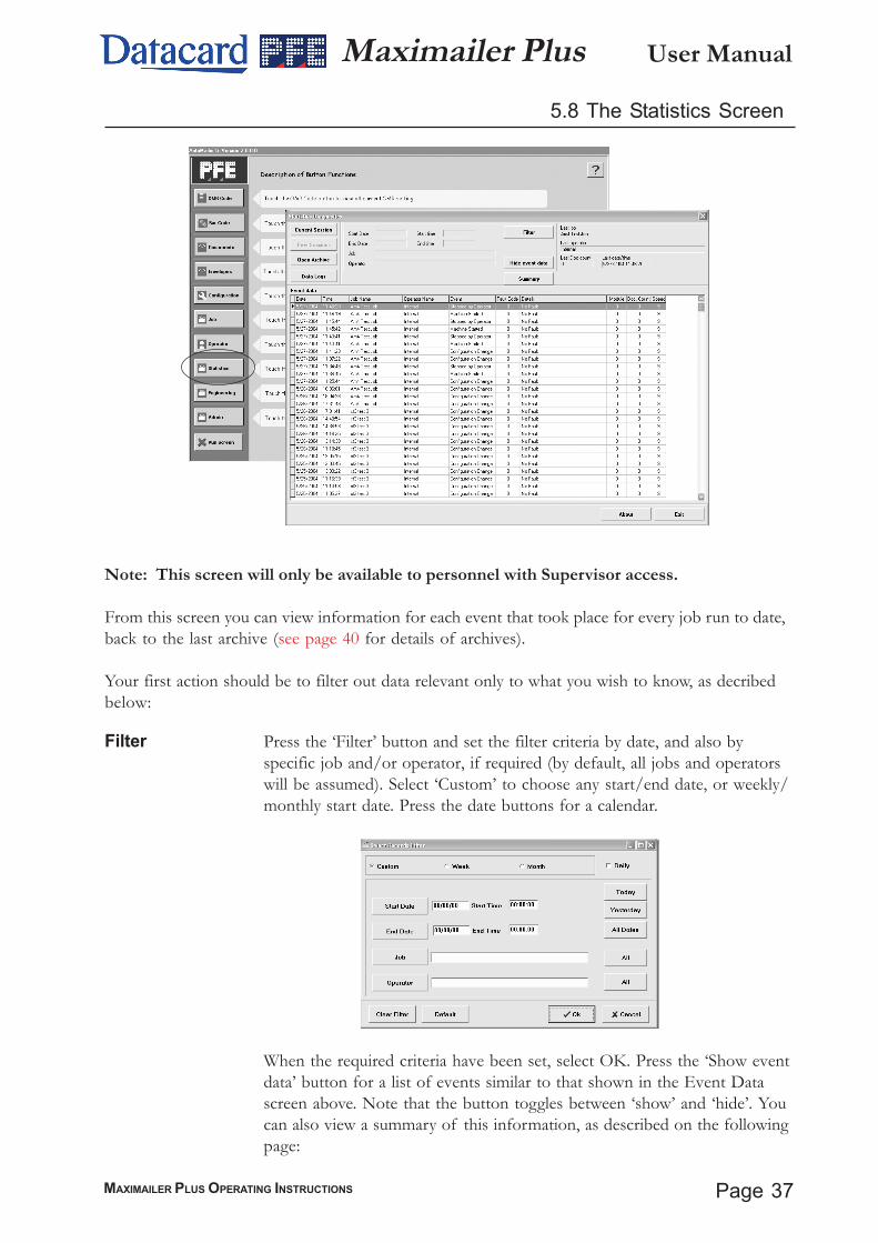
User ManualMaximailer Plus5.8 The Statistics Screen
Note: This screen will only be available to personnel with Supervisor access.
From this screen you can view information for each event that took place for every job run to date,back to the last archive (see page 40 for details of archives).
Your first action should be to filter out data relevant only to what you wish to know, as decribedbelow:
Filter Press the ‘Filter’ button and set the filter criteria by date, and also byspecific job and/or operator, if required (by default, all jobs and operatorswill be assumed). Select ‘Custom’ to choose any start/end date, or weekly/monthly start date. Press the date buttons for a calendar.
When the required criteria have been set, select OK. Press the ‘Show eventdata’ button for a list of events similar to that shown in the Event Datascreen above. Note that the button toggles between ‘show’ and ‘hide’. Youcan also view a summary of this information, as described on the followingpage:

User Manual
Page 38 MAXIMAILER PLUS OPERATING INSTRUCTIONS
Maximailer Plus
View Summary
5.8 The Statistics Screen (contd.)
Press the ‘Summary’ button to view the filtered data. Note that only validevents will be shown, ie. those that involved documents being fed (a machineconfiguration event, for example, would not be shown).
Select an event and press ‘OK’ to view the summary, as shown above. Notethat you can also select more than one event by selecting the first in a range,holding down the shift key and then selecting the last in the range.Alternatively, all events can be selected by pressing the ‘Select All’ button.If a printer is connected, the summary can be printed by pressing the ‘Print’button. The data will be collated and printed in portrait format.
Press the ‘Current’ button to view only the events that have occurred sincelast logging on. The ‘Previous’ button shows events up to the last new logon.If a new archive is opened (see page 40), the ‘Previous’ button will restorethe events that were displayed prior to its opening.
continued overleaf
Current & Previ-ous sessions
Page 39MAXIMAILER PLUS OPERATING INSTRUCTIONS
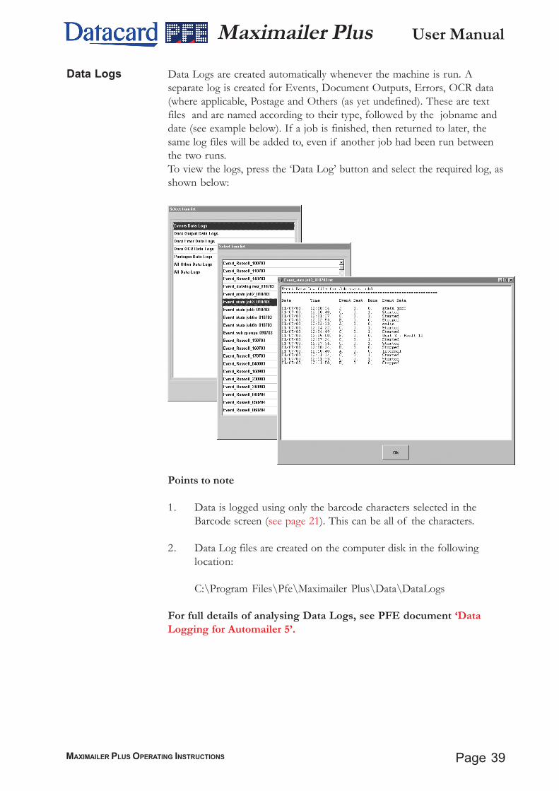
User ManualMaximailer PlusData Logs are created automatically whenever the machine is run. Aseparate log is created for Events, Document Outputs, Errors, OCR data(where applicable, Postage and Others (as yet undefined). These are textfiles and are named according to their type, followed by the jobname anddate (see example below). If a job is finished, then returned to later, thesame log files will be added to, even if another job had been run betweenthe two runs.To view the logs, press the ‘Data Log’ button and select the required log, asshown below:
Points to note
1. Data is logged using only the barcode characters selected in theBarcode screen (see page 21). This can be all of the characters.
2. Data Log files are created on the computer disk in the followinglocation:
C:\Program Files\Pfe\Maximailer Plus\Data\DataLogs
For full details of analysing Data Logs, see PFE document ‘DataLogging for Automailer 5’.
Data Logs
User Manual
Page 40 MAXIMAILER PLUS OPERATING INSTRUCTIONS
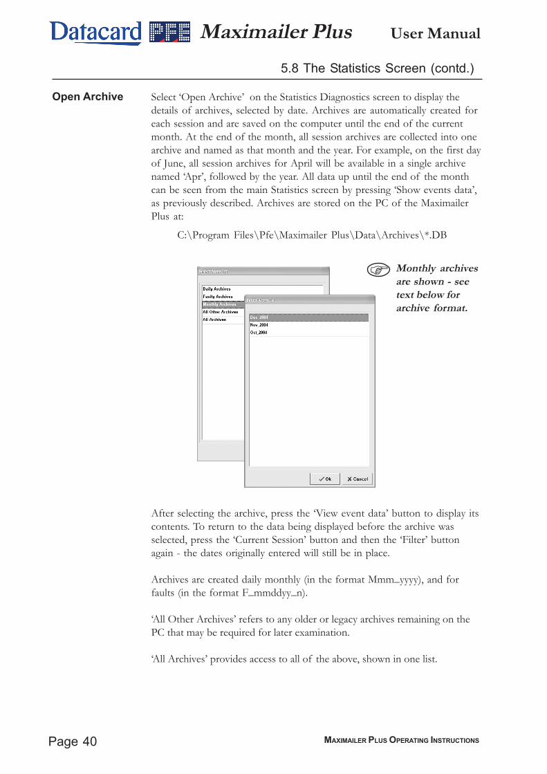
Maximailer Plus5.8 The Statistics Screen (contd.)
Select ‘Open Archive’ on the Statistics Diagnostics screen to display thedetails of archives, selected by date. Archives are automatically created foreach session and are saved on the computer until the end of the currentmonth. At the end of the month, all session archives are collected into onearchive and named as that month and the year. For example, on the first dayof June, all session archives for April will be available in a single archivenamed ‘Apr’, followed by the year. All data up until the end of the monthcan be seen from the main Statistics screen by pressing ‘Show events data’,as previously described. Archives are stored on the PC of the MaximailerPlus at:
C:\Program Files\Pfe\Maximailer Plus\Data\Archives\*.DB
After selecting the archive, press the ‘View event data’ button to display itscontents. To return to the data being displayed before the archive wasselected, press the ‘Current Session’ button and then the ‘Filter’ buttonagain - the dates originally entered will still be in place.
Archives are created daily monthly (in the format Mmm_yyyy), and forfaults (in the format F_mmddyy_n).
‘All Other Archives’ refers to any older or legacy archives remaining on thePC that may be required for later examination.
‘All Archives’ provides access to all of the above, shown in one list.
Open Archive
Monthly archivesare shown - seetext below forarchive format.
Page 41MAXIMAILER PLUS OPERATING INSTRUCTIONS
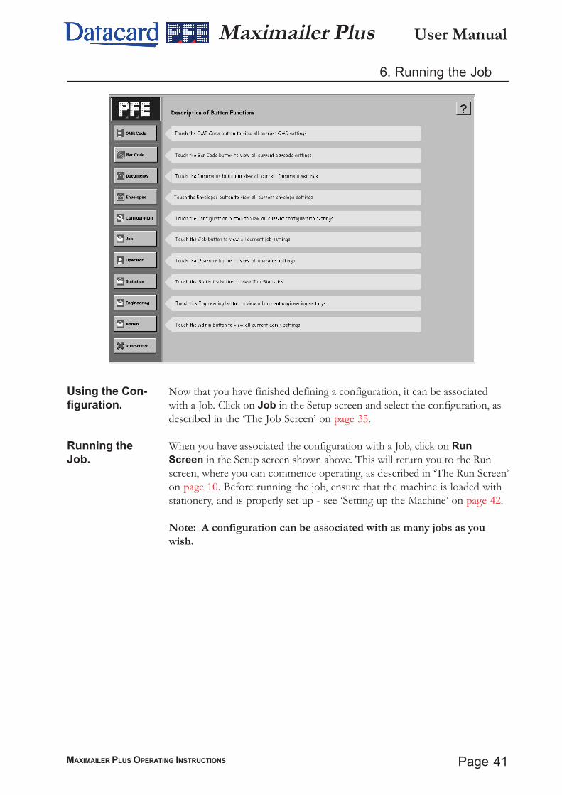
User ManualMaximailer Plus6. Running the Job
Using the Con-figuration.
Running theJob.
Now that you have finished defining a configuration, it can be associatedwith a Job. Click on Job in the Setup screen and select the configuration, asdescribed in the ‘The Job Screen’ on page 35.
When you have associated the configuration with a Job, click on RunScreen in the Setup screen shown above. This will return you to the Runscreen, where you can commence operating, as described in ‘The Run Screen’on page 10. Before running the job, ensure that the machine is loaded withstationery, and is properly set up - see ‘Setting up the Machine’ on page 42.
Note: A configuration can be associated with as many jobs as youwish.
User Manual
Page 42 MAXIMAILER PLUS OPERATING INSTRUCTIONS
Maximailer Plus7. Setting up the Machine
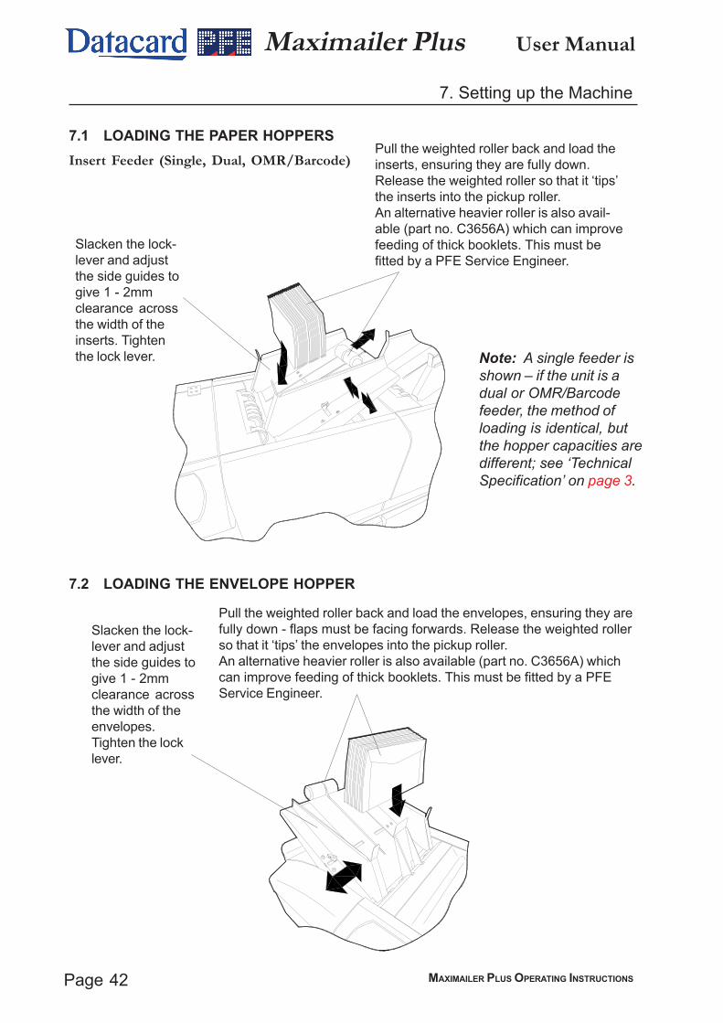
7.1 LOADING THE PAPER HOPPERSInsert Feeder (Single, Dual, OMR/Barcode)
Slacken the lock-lever and adjustthe side guides togive 1 - 2mmclearance acrossthe width of theinserts. Tightenthe lock lever.
Pull the weighted roller back and load theinserts, ensuring they are fully down.Release the weighted roller so that it ‘tips’the inserts into the pickup roller.An alternative heavier roller is also avail-able (part no. C3656A) which can improvefeeding of thick booklets. This must befitted by a PFE Service Engineer.
Note: A single feeder isshown – if the unit is adual or OMR/Barcodefeeder, the method ofloading is identical, butthe hopper capacities aredifferent; see ‘TechnicalSpecification’ on page 3.
7.2 LOADING THE ENVELOPE HOPPER
Pull the weighted roller back and load the envelopes, ensuring they arefully down - flaps must be facing forwards. Release the weighted rollerso that it ‘tips’ the envelopes into the pickup roller.An alternative heavier roller is also available (part no. C3656A) whichcan improve feeding of thick booklets. This must be fitted by a PFEService Engineer.
Slacken the lock-lever and adjustthe side guides togive 1 - 2mmclearance acrossthe width of theenvelopes.Tighten the locklever.
Page 43MAXIMAILER PLUS OPERATING INSTRUCTIONS
User ManualMaximailer Plus7. Setting up the Machine (contd.)
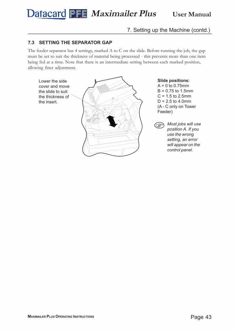
7.3 SETTING THE SEPARATOR GAPThe feeder separator has 4 settings, marked A to C on the slide. Before running the job, the gapmust be set to suit the thickness of material being processed - this prevents more than one itembeing fed at a time. Note that there is an intermediate setting between each marked position,allowing finer adjustment.
Lower the sidecover and movethe slide to suitthe thickness ofthe insert.
Slide positions:A = 0 to 0.75mmB = 0.75 to 1.5mmC = 1.5 to 2.5mmD = 2.5 to 4.0mm(A - C only on TowerFeeder)
Most jobs will useposition A. If youuse the wrongsetting, an errorwill appear on thecontrol panel.
User Manual
Page 44 MAXIMAILER PLUS OPERATING INSTRUCTIONS
Maximailer Plus8. Operator Maintenance
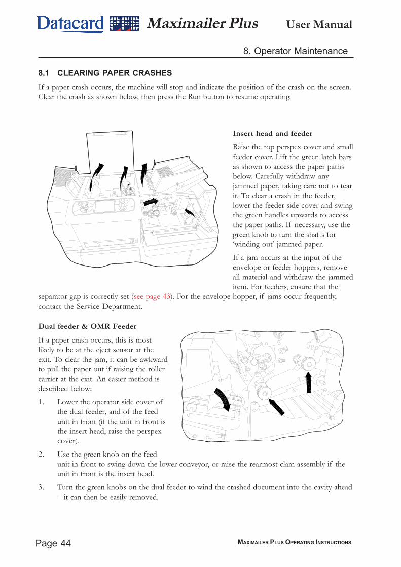
8.1 CLEARING PAPER CRASHESIf a paper crash occurs, the machine will stop and indicate the position of the crash on the screen.Clear the crash as shown below, then press the Run button to resume operating.
Insert head and feederRaise the top perspex cover and smallfeeder cover. Lift the green latch barsas shown to access the paper pathsbelow. Carefully withdraw anyjammed paper, taking care not to tearit. To clear a crash in the feeder,lower the feeder side cover and swingthe green handles upwards to accessthe paper paths. If necessary, use thegreen knob to turn the shafts for‘winding out’ jammed paper.
If a jam occurs at the input of theenvelope or feeder hoppers, removeall material and withdraw the jammeditem. For feeders, ensure that the
separator gap is correctly set (see page 43). For the envelope hopper, if jams occur frequently,contact the Service Department.
Dual feeder & OMR FeederIf a paper crash occurs, this is mostlikely to be at the eject sensor at theexit. To clear the jam, it can be awkwardto pull the paper out if raising the rollercarrier at the exit. An easier method isdescribed below:
1. Lower the operator side cover ofthe dual feeder, and of the feedunit in front (if the unit in front isthe insert head, raise the perspexcover).
2. Use the green knob on the feedunit in front to swing down the lower conveyor, or raise the rearmost clam assembly if theunit in front is the insert head.
3. Turn the green knobs on the dual feeder to wind the crashed document into the cavity ahead– it can then be easily removed.

Page 45MAXIMAILER PLUS OPERATING INSTRUCTIONS
User ManualMaximailer Plus8. Operator Maintenance (contd.)
8.2 CLEANING ROLLERS AND SENSORSPeriodically, all rollers, feed wheels and sensors should be cleaned, especially if a long run isenvisaged. Use only PFE Rubber Riller Restorer Fluid (part no. E0483A), except for the pick-uprollers on the feed and envelope hoppers - these must be cleaned using only a cloth damp-ened with water. Clean the full circumference of rubber rollers, feed wheels and conveyors in thearea of:
a) Feeder and envelope hoppers
b) Insert area at the head end
c) Closer area at the head end
Ensure the machine is switched off before cleaning rollers or sensors.To access rollers in the insert area, raise the perspex cover and lift the green handles to reach thepaper path. Rotate rollers by hand when cleaning.
To access feeder rollers, lower the LH side cover and lift the infill cover in front of the hopper.Use the green knob to rotate the rollers for cleaning. Note: after a long period of time, someinserts can cause a jam with the insert stuck between the rollers - this may especially occur oncoated material. If this happens, open the upper roller plate with the green latch and using a clothdampened with Roller Cleaning Fluid, clean all the rollers, both upper and lower. Use the greenknob to help rotate them.
Cleaning sensorsWhen cleaning the rollers, the sensors should also be cleaned by blowing away dust and debrisusing the supplied airduster. It is important that sensors are regularly cleaned, or operatingerrors may occur. Locations are shown on the following page - note that each sensor is in twohalves, receiver and transmitter. Both halves must be cleaned.
Use only non-flammable airdusters, such as supplied by PFE (part no. A0070A).
Clean all 12 rollers
User Manual
Page 46 MAXIMAILER PLUS OPERATING INSTRUCTIONS
Maximailer Plus
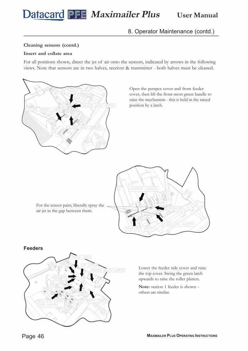
Cleaning sensors (contd.)Insert and collate areaFor all positions shown, direct the jet of air onto the sensors, indicated by arrows in the followingviews. Note that sensors are in two halves, receiver & transmitter - both halves must be cleaned.
For the sensor pairs, liberally spray theair jet in the gap between them.
Open the perspex cover and front feedercover, then lift the front-most green handle toraise the mechanism - this is held in the raisedposition by a latch.
Lower the feeder side cover and raisethe top cover. Swing the green latchupwards to raise the roller platten.
Note: station 1 feeder is shown -others are similar.
Feeders
8. Operator Maintenance (contd.)
Page 47MAXIMAILER PLUS OPERATING INSTRUCTIONS
User ManualMaximailer Plus
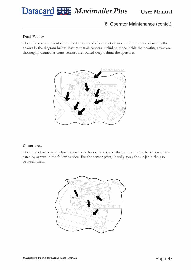
Closer areaOpen the closer cover below the envelope hopper and direct the jet of air onto the sensors, indi-cated by arrows in the following view. For the sensor pairs, liberally spray the air jet in the gapbetween them.
8. Operator Maintenance (contd.)
Dual FeederOpen the cover in front of the feeder trays and direct a jet of air onto the sensors shown by thearrows in the diagram below. Ensure that all sensors, including those inside the pivoting cover arethoroughly cleaned as some sensors are located deep behind the apertures.
User Manual
Page 48 MAXIMAILER PLUS OPERATING INSTRUCTIONS
Maximailer Plus9. Operator Maintenance (contd.)
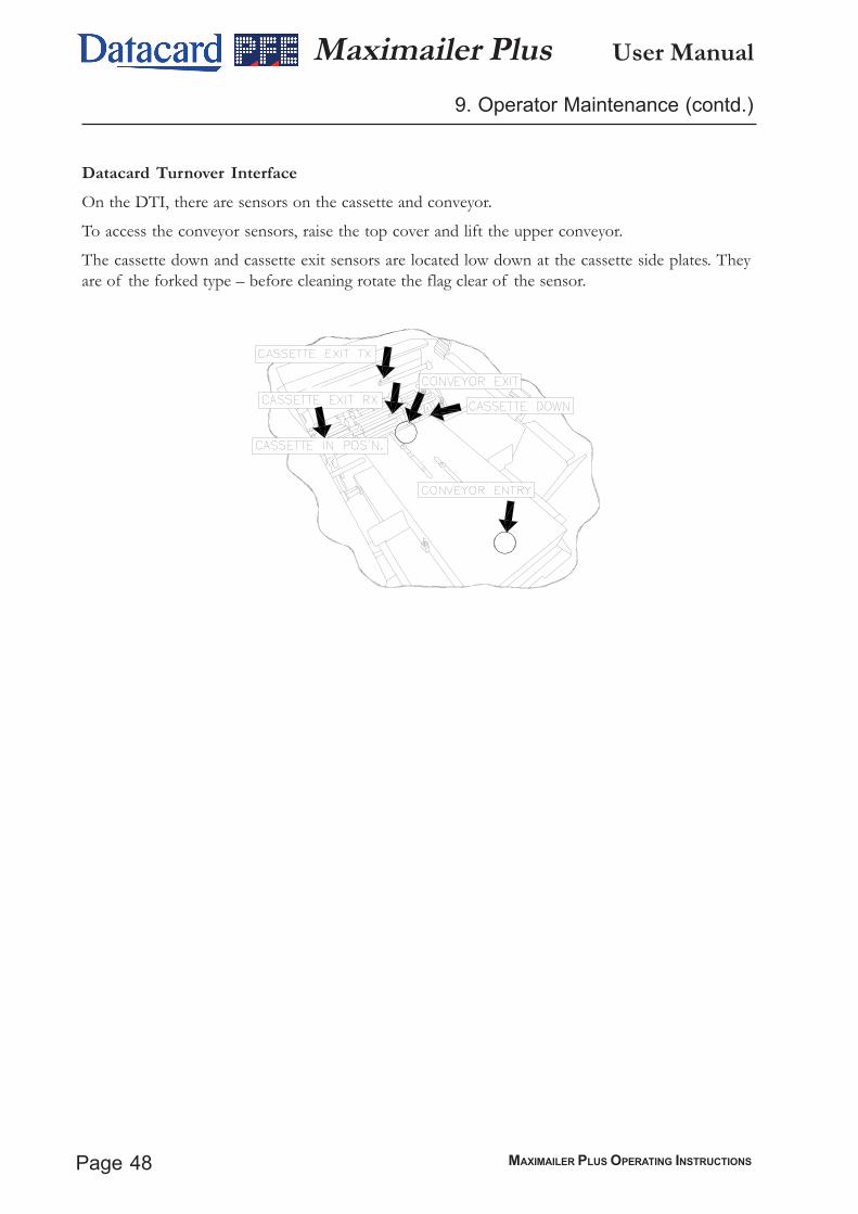
Datacard Turnover InterfaceOn the DTI, there are sensors on the cassette and conveyor.
To access the conveyor sensors, raise the top cover and lift the upper conveyor.
The cassette down and cassette exit sensors are located low down at the cassette side plates. Theyare of the forked type – before cleaning rotate the flag clear of the sensor.

Page 49MAXIMAILER PLUS OPERATING INSTRUCTIONS
User ManualMaximailer Plus9. Operator Maintenance (contd.)
9.3 MAINTAINING THE WETTING SYSTEMThe wetter tank supplies the fluid for wetting the envelope flaps and needs topping up fromtime to time. It is located on the left hand side of the machine, below the closer area at theoutput. To gain access, lower the side cover on the insert head. Fill the tank through thespout until the level reaches the indicator visible inside - be careful not to overfill.
Note: Use only PFE Envelope Sealing Fluid A0276A, as this has been speciallyformulated for greatly enhanced sealing and antibacterial qualities.
Check the condition of the sponge at regular intervals and clean off gum residues as re-quired. Remove the wetter tank to do this by lifting the end slightly using the green tab, thenwithdraw it. Note: use a piece of absorbent material to under the drain tube to catchany drips. Clean the sponge under running water and replace the tank, ensuring it is fullylocated. After cleaning, or if the sponge has dried out, it should be primed by immersing itin Envelope Sealing Fluid.
If the machine is to be left unattended for more than a week, it is advisable to remove thetank and drain it. Wipe dry after washing to prevent contamination.The tank must also be removed if the machine is moved, and the reservoirdrained. The reservoir can be drained by pulling out the plastic drain tube tucked under-neath it and pulling out the bung to drain into a suitable receptacle.
Fill through the spoutas shown, up to thelevel indicator.
Withdraw the tank byusing the green tab
User Manual
Page 50 MAXIMAILER PLUS OPERATING INSTRUCTIONS
Maximailer Plus
Blank Page