Embed Size (px)
Citation preview

Maxicom2 User Manual Addendum
Rain Bird Corporation
Contractor Division
970 West Sierra Madre Avenue
Azusa, CA 91702
Phone: (626) 963-9311
Fax: (626) 812-3411
Rain Bird Corporation
Commercial Division
6991 East Southpoint Road
Tucson, AZ 85706
Phone: (520) 741-6100
Fax: (520) 741-6522
Rain Bird International, Inc.
145 North Grand Avenue
Glendora, CA 91741
Phone: (626) 963-9311
Fax: (626) 963-4287
Specification Hotline
800-458-3005 (U.S. & Canada only)
Rain Bird Technical Services
1-866-477-9778 (U.S. & Canada only)
www.rainbird.com
® Registered Trademark of Rain Bird Corporation
© 2005 Rain Bird Corporation 4/05

Maxicom2 User Manual Addendum
21-Dec-05 Copyright © 2005 Rain Bird Corporation Page 2
INDEX
MAXICOM2 SYSTEM OVERVIEW...................................................................................................................... 4
SYSTEM HARDWARE REQUIREMENTS.......................................................................................................... 7
MINIMUM HARDWARE AND SOFTWARE REQUIREMENTS ......................................................................................... 7
RECOMMENDED HARDWARE AND SOFTWARE REQUIREMENTS................................................................................ 7
ENVIRONMENTAL CONDITIONS ................................................................................................................................ 8
DATABASE INTEGRATION......................................................................................................................................... 8
USING A CD BURNER FOR DATABASE BACKUP ....................................................................................................... 8
CENTRAL CONTROLLER TO CCU CONNECTION SPEED ............................................................................................ 9
NUMBERING SCHEDULES................................................................................................................................. 10
SIMPLISTIC TO COMPLEX SCHEDULE NUMBERING ................................................................................................. 10
CYCLIC WATERING PATTERN SCHEDULE NUMBERING .......................................................................................... 10
HORTICULTURAL BASED SCHEDULE NUMBERING ................................................................................................. 11
MASTER SCHEDULE NUMBERING........................................................................................................................... 11
NAMING SCHEDULES......................................................................................................................................... 12
COMMAND EXAMPLES...................................................................................................................................... 13
BASIC COMMANDS IN SCHEDULES.............................................................................................................. 14
LINK COMMANDS IN SCHEDULES................................................................................................................ 16
SENSOR COMMANDS IN SCHEDULES .......................................................................................................... 19
SCHEDULE EXAMPLES...................................................................................................................................... 25
CONTROL SCHEDULES .................................................................................................................................... 27Step Schedule Execution .............................................................................................................................................27
Irrigation Scheduling by Odd-Even patterns................................................................................................................27
Irrigation Scheduling by Day Cycles ...........................................................................................................................28
Master Schedules .........................................................................................................................................................29
Multiple Station Control ..............................................................................................................................................30
Complex Schedule Cycles (Every Third Day, Excluding Sundays) ............................................................................32
Master Valve Control ..................................................................................................................................................34
Control of Fountains and Other Non-Irrigation Devices..............................................................................................35
MONITORING SCHEDULES ............................................................................................................................. 36Rain Watch (reaction to rain at the site).......................................................................................................................36
Rain Cancel (Cancel irrigation if rain detected)...........................................................................................................38
Wind Watch (reaction to wind at the site) ..................................................................................................................39
Freeze Watch (reaction to temperature at the site).......................................................................................................42
Flo Watch – Log Flow.................................................................................................................................................44
Flo Watch – LOW FLOW ...........................................................................................................................................45
Flo Watch – SEEF .......................................................................................................................................................46
SEEF – Normally Open Master Valve.........................................................................................................................47
MAXICOM2 INDICATIONS AND OPERATIONS............................................................................................ 48
IRRIGATION PROPERTIES IN MAXICOM2
................................................................................................................. 48Crop Coefficient ..........................................................................................................................................................48
Soil Moisture Holding Capacity ..................................................................................................................................48
Soil Infiltration Rate ....................................................................................................................................................49
Landscape Coefficient .................................................................................................................................................49
Cycle + SoakTM............................................................................................................................................................50
MAXICOM2 ICON – RIGHT CLICK OPTIONS............................................................................................................. 52
MAXICOM2 WARNING SYSTEM .............................................................................................................................. 52
RAIN SHUT DOWN.................................................................................................................................................. 52
RUNTIME ROSTER NUMBER COLORS ..................................................................................................................... 53
EXPLANATION OF ET STATUS ................................................................................................................................ 53
MAXIMUM DAILY ET VALUE ................................................................................................................................ 54
ET STACKING ........................................................................................................................................................ 54
RELATIONSHIP BETWEEN MINIMUM, MAXIMUM, AND IRRIGATION ET.................................................................. 56
WEATHER STATION CONTACTS AND ET DATA...................................................................................................... 57

Maxicom2 User Manual Addendum
21-Dec-05 Copyright © 2005 Rain Bird Corporation Page 3
SITE RAIN CAN ACCOUNTING IN IRRIGATION ET................................................................................................... 57
EFFECT OF RAIN ON IRRIGATION ET (SCHEDULES THAT DO NOT RUN EVERY DAY)................................................ 58
RUNNING STATIONS FOR SECONDS ........................................................................................................................ 58
USING A PAGER WITH MAXICOM2.......................................................................................................................... 59
ACTIVATING DOOR LOCKS WITH MAXICOM2......................................................................................................... 60
CCU OPERATIONS............................................................................................................................................... 61SENDING CONFIGURATION CHANGES TO THE CCU ................................................................................................ 61
CCU POLLING OF RADIO LINK SATELLITES........................................................................................................... 61
WIRELESS DIAGNOSTICS ........................................................................................................................................ 62
FLOW METER SETTINGS (GALLONS PER PULSE) .................................................................................................... 63
FLOW LOGGING AND PULSE DECODER LIMITS....................................................................................................... 63
FLO-MANAGER ...................................................................................................................................................... 65
STATIONS 12 OR 24 AVAILABLE FOR SEEF OPERATIONS ...................................................................................... 65
STATIONS RUNNING WHILE SEEF ACTIONS ARE OCCURRING ................................................................................ 66
MASTER VALVE OPTIONS................................................................................................................................ 67
NORMALLY CLOSED MASTER VALVE .................................................................................................................... 67
NORMALLY OPEN MASTER VALVE ........................................................................................................................ 67
ONE MASTER VALVE WITH MULTIPLE SATELLITES ............................................................................................... 68
FREEDOM FOR MAXICOM2.............................................................................................................................. 70
FREEDOM COMMANDS........................................................................................................................................ 70
FREEDOM SYSTEM RESPONSES .............................................................................................................................. 71
FREEDOM RUN TIME VERSUS CONTROLLER STATION COUNT................................................................................ 71

Maxicom2 User Manual Addendum
21-Dec-05 Copyright © 2005 Rain Bird Corporation Page 4
MAXICOM2 SYSTEM OVERVIEW
Maxicom2 is a hardware and software package that offers genuine central management of irrigation
systems. Maxicom2 manages irrigation systems by sending out instructions, or schedules, and by
constantly monitoring feedback to verify the instructions are carried out. Maxicom2 can monitor current
flow, check for breaks or leaks and turn off the offending zone or main line Maxicom2 manages flow
throughout the entire system to take maximum advantage of available water and to prevent mainlinesfrom exceeding their capacities. Maxicom
2 can also control and monitor lights, fountains, security
systems, etc.
The immediate savings are in water and labor. Most controller run sites are over-watered; Maxicom2 can
use evapotranspiration (ET) based scheduling to replace only the amount of water lost throughevaporation and transpiration, or plant use. It is not unusual for new Maxicom
2 users to reduce water
usage by 25-40% in the first year. Labor costs are reduced because physically monitoring a site forbreaks, stuck valves, or missing nozzles is no longer necessary.
The long-term benefit is a healthier, more attractive landscape at a reduced maintenance cost. This isaccomplished by automatically applying the proper amount of water at the proper time. Many of themore visibly troubling aspects of an irrigation system, such as watering in the rain, broken heads, andwatering at inconvenient times are eliminated. Over-watering, and it’s resulting problems, such asincreased susceptibility to disease and decreased playability on sports fields are reduced.
The major components of a Maxicom2 System are:
Central Controller
Maxicom2 is shipped pre-installed in a Gold (Desktop) or Laptop Dell Computer package. The Central
Controller should be located in the Water Manager’s office and should be dedicated only to Maxicom2.
The computer may be accessed from a remote computer with PCAnywhere software, which is also pre-installed. The software has password protection that allows users at remote locations to access onlytheir sites to input data or make changes. A master password gives the Water Manager access to allsites.
Cluster Control Unit
The Cluster Control Unit (CCU) is a computer without a keyboard or screen and is the “middle manager”between the software and the field devices at each site. It controls and monitors groups, or “clusters” offield satellites and other devices, such as flow and rain sensors.
Schedules are automatically downloaded from the Central Controller to the Cluster Control Unit at auser-entered time, usually late a night just before the irrigation cycle begins.
Schedules are then sent from the CCU to the appropriate satellites. The CCU monitors site conditionsconstantly; the results are automatically uploaded to the Central Controller at a user-entered time,usually after the irrigation cycle is complete.
The CCU28 can control and monitor twenty-eight devices, or channels; the CCU6 can control canmonitor six. One Central Controller can monitor an unlimited number of Cluster Control Units at distantsites. Cluster Control Units are available in wall-mount cabinets and stainless steel pedestals.
Maxicom2 User Manual Addendum
21-Dec-05 Copyright © 2005 Rain Bird Corporation Page 5
Satellites
In a Maxicom2 system, satellites replace traditional field controllers. A satellite contains an interface
board, which allows communication between the CCU and the satellite. The most common satellite isthe ESP-SAT.
The ESP-SAT is a very user-friendly “hybrid” satellite, using both solid-state and electro-mechanicalcomponents. It is available in twelve, sixteen, twenty-four, thirty-two and forty station configurations, inwall-mount cabinets and stainless steel pedestals.
Site Satellite
The Site Satellite combines an ESP-SAT and many of the functions of a Cluster Control Unit in onecabinet. The CCU portion of the Site Satellite controls and monitors that one satellite and up to twosensor inputs, without the use of Decoders.
The Site Satellite is available in twelve, sixteen, twenty-four, thirty-two, and forty station configurations, inwall mount cabinets and stainless steel pedestals. It is ideal for smaller sites with forty or fewer zonesand one point of connection.
Communication Path
There are two significant communication paths in Maxicom2 systems: The Central Controller data path
and the Satellite data path. The Central Controller data path is from the Central Controller to the CCU(or Site Satellite) and can be hardwire, telephone modem, or radio. The Satellite data path is from theCCU to the Satellites and can be hardwire (Two-Wire) or radio (Link). A Site Satellite has no satellitedata path, since the CCU portion communicates only with the Satellite and Sensor Inputs inside thesame cabinet.
Decoders
Like Satellites, Decoders are “field devices”; they are wired into the Maxicom2 Two-Wire path and use a
channel on the CCU. Decoders bring inputs into Maxicom2 by “decoding” the input device language.
There are two types of decoders: pulse and sensor.
Pulse Decoders monitor pulses created by sensing devices, such as flow sensors. Pulse Decoders areused with inputs measured over time, such as gallons per minute, or miles per hour. Sensor Decodersmonitor on/off devices, such as freeze or moisture sensors. Monitoring schedules are written that allowthe irrigation schedules to react to field conditions recorded in the CCU by the Decoders.
Decoders are used only in Two-Wire systems; in Link Radio systems or Site Satellites, sensors are wireddirectly into the Satellite or Site Satellite.
Flow Sensors and Master Valves
Flow Sensors and Master Valves are installed at each point of connection in an irrigation systemcontrolled by Maxicom
2. The sensor reports current flow to the CCU or Site Satellite through an output
transmitter and a Pulse Decoder (when a Two-Wire path is used). The CCU or Site Satellite comparesactual flow to projected theoretical flow. When an excess flow condition occurs, Maxicom
2 can isolate the
problem to one zone or the entire system and shut off the offending zone valve or master valve. FlowSensors are also useful for logging water usage in a zone or an entire site.

Maxicom2 User Manual Addendum
21-Dec-05 Copyright © 2005 Rain Bird Corporation Page 6
Site Rain Gauge
The Site Rain Gauge measures rainfall over time in hundredths of an inch and reports that information tothe Cluster Control Unit or Site Satellite. Monitoring schedules pause or interrupt irrigation schedulesusing user-entered thresholds. Systems with multiple sites can have Site Rain Gauges at each site formaximum accuracy. Site rainfall data can also be used to fine tune ET for a site when its associatedweather station is at a remote site.
Weather Station
The Weather Station gathers minimum and maximum temperatures, wind speed, rainfall, solar radiation,and humidity data. At a user-entered time, Maxicom
2 contacts the Weather Station and downloads the
data, usually just before the irrigation cycle. Maxicom2 converts the data to an ET figure, which is used to
fine-tune the runtimes of all irrigation schedules. In this way, Maxicom2 replaces precisely the water lost
during the previous day to evaporation and transpiration. If schedules are not written to run every day,Maxicom
2 keeps a running total of ET and replaces the total since the last day the schedule ran.
Freedom System
The Freedom System allows remote access to the Maxicom2 Central Controller through either a radio or
a phone. The operator can start, stop, pause, and advance schedules or stations from the field using thekeypad of the radio or phone.

Maxicom2 User Manual Addendum
21-Dec-05 Copyright © 2005 Rain Bird Corporation Page 7
SYSTEM HARDWARE REQUIREMENTS
In order to run the Maxicom2 software, your Central Controller (computer system) must meet certain
requirements. Below is a list of minimum hardware and software requirements. The recommendedhardware and software requirements, also listed here, will maximize the speed of your Maxicom
2
software.
Minimum Hardware and Software RequirementsFor customers who purchased Maxicom
2 Software ONLY (pre-1999), the Central Controller you use to
run the Maxicom2 software must meet or exceed the following minimum requirements:
• Intel® Pentium® 166 MHz or faster processor• 32 megabytes RAM• Standard SVGA monitor (800 x 600, 256 colors)• Mouse• 101-key standard keyboard• 2 GB hard disk drive• 3.5 inch floppy disk drive• CD-ROM drive• One free serial port for communication with Rain Bird Cluster Control Units (CCUs)• Windows 98SE or NT software• Printer
Maxicom2 does not require more than 100 megabytes of hard disk space above the operating system for
a full installation. Actual disk space requirements may be greater with use, depending upon the amountof logged historical data and the number of sites. Maxicom
2 is not designed to operate on a computer
with a non-Intel Pentium-based microprocessor for the primary central processing unit.
Recommended Hardware and Software RequirementsThe current specifications of the Rain Bird Maxicom
2 Central Controller and the recommended
requirements for existing software-only users for running Maxicom2:
• Pentium® IV 2.8 GHz or faster processor• 512 megabytes RAM• 17” Visible Flat Panel monitor• 101-key standard AT keyboard• 40 GB, 7200 RPM hard disk drive• 3.5 inch floppy disk drive• 48X CD-RW drive with Roxio Easy CD Creator software• 2 button Mouse with scroll• U.S. Robotics 56K* V.92 External Faxmodem (two)
• DIGI ClassicBoard (four serial ports)• WindowsXP Professional Operating System, SP1 (minimum), NTFS• Integrated Video• Sound card and speakers• Printer• Symanec PCAnywhere version 10.5 (at least) software• Uninterruptible Power Supply (UPS)
Port(s) / Connector Type: RJ11 / USBPower Provided: 650 VA (360 Watts)Output Connector(s): 8 Outlets with Surge Protection; 4 Outlets provide battery backup

Maxicom2 User Manual Addendum
21-Dec-05 Copyright © 2005 Rain Bird Corporation Page 8
Environmental Conditions
Based on the policies of the computer manufacturer, the recommended environmental conditions for theMaxicom
2 Central Controller are:
TemperatureOperating: 10° to 35°C (50° to 95°F)Non-operating: -40° to 65°C (-40° to 149°F)
Relative Humidity20% to 80% (non-condensing)
While these are the specified environmental conditions, the customer should be aware that they are nota guarantee of proper operation. The computer manufacturer holds that as the extremes areapproached, performance will degrade, and possibly lead to a system shutdown. Adverse environmentalconditions may also lead to an increase in deterioration rate of system components.
It is the recommendation of Rain Bird Corporation that Maxicom2 customers house their Central
Controller in a controlled environment (indoors, air-conditioned), in order to optimize system performanceand maximize lifespan of system components.
Database Integration
It is the current policy of Rain Bird Corporation to discourage the practice of integration with or “pullingdata from” the live Maxicom Database. While it may be possible to have other applications accessingthe database concurrently with Maxicom, it cannot be guaranteed, and in some cases, the associatedapplication may interfere with operations of the Central Control system.
We recommend that customers do not attempt to pull real-time data from the live Maxicom Database.Maxicom has been set up with an Export Database, to allow use of data in other applications. It shouldbe noted, however, that the Export Database is not a real-time representation of data.
Since Rain Bird Corporation can not guarantee operation of Maxicom in conjunction with anotherapplication accessing the live database, any attempt at such integration will void the Maxicom Warrantyand any guarantee of support, should the customer be a Support Plan subscriber.
Using a CD Burner for Database Backup
The following is a description of how to use a CD Burner (now shipping on Rain Bird Central Controllers)for Maxicom
2 Database Backup. Please note: You should have Roxio Easy CD Creator software (or
equivalent, e.g. Sonic DLA, etc) on the computer (ships with the Maxicom2 Central Controllers). The
process to Backup to CD is as follows (using Roxio Easy CD Creator as example):
1) Place a blank CD in the CD drive (burner). You want to navigate to the Roxio Project Selectorprogram, but this should automatically start when a blank CD is put into the drive. Otherwise, itshould be found under Start> Programs> Roxio Easy CD Creator.
2) When the Project Selector starts, hover the mouse over the "Make a Data CD" option.3) Three new options will appear to the right, but the bottom most option will be grayed out. The top
option is the "Direct CD" option, which allows you to set up a CD to drag and drop files fromWindows Explorer.
4) Once “Direct CD” is chosen, the user will be taken to a new screen. This will be the Direct CDFormat Utility. This screen will have a button right in the middle of the page that says "Format CD."
Maxicom2 User Manual Addendum
21-Dec-05 Copyright © 2005 Rain Bird Corporation Page 9
Pressing this will start the CD formatting, which will take about 15 minutes. When it completes, youshould be able to select the CD drive as a backup option in MC2.
Central Controller to CCU Connection Speed
Regarding CCU (Or ESP-SITE-Satellite) to Central Controller modem connection rates:
Prior to version 5.70R, the CCU was capable of 300 or 1200 bps (some older CCUs are only capable of300 bps). Version 5.70R and later are capable of 300/1200/2400 bps. When a site is created in MC2,the speed is set by default to 1200 bps. To get 2400 bps, this speed must be changed in Site Properties(Site Properties > Contact Tab > Communication Port Settings). The speed options in theCommunication Port Settings also lists 9600 bps. This speed is, currently, not achievable.
In order to achieve 2400 bps, the CCU also needs the most recent modem board. You can identify themost recent modem boards by the fact that the phone connection AND the RS232 Direct Connect portsare all on the lower edge of the board. Another identifying attribute is the Cermetek Modem Module onthe board.

Maxicom2 User Manual Addendum
21-Dec-05 Copyright © 2005 Rain Bird Corporation Page 10
NUMBERING SCHEDULES
Numbering schedules can play an important part in how easy Maxicom2 is to use. Maxicom
2 allows you
to set up any type of numbering system you desire. The most important aspects of deciding how tonumber your schedules is 1) that it is easy for you to use, and 2) that the system can expand in thefuture if your Site grows.
With all the following examples, there is one common factor. This factor is that the tens and ones digitsdesignate the channel number with which a schedule works. An example would be: Schedule number413 is a 400 series schedule operating channel number 13. Since there are a maximum of 28 channelsavailable on a CCU, numbers 1 to 28 are used for this designation. Numbers above 28 can be used forlinked schedules or miscellaneous schedules.
Maxicom2 can also sort schedules by numbers. This allows the user to list only those schedules in a
certain group or range. When numbering schedules, you can group schedules of common usage orfunction with the same first digit(s). This will allow the user to sort and list only the schedules in thisgroup for easier identification.
Below are some examples of how some Maxicom2 users have formulated numbering systems to fit their
needs:
Simplistic to Complex Schedule Numbering
This type of numbering system is very vague and open. The user starts with the lower numbers in thefirst attempt to program schedules. As the user becomes more familiar with programming, the largernumbers are used for more complex programs. The tens and ones digits are used to designate thechannel number operated by the schedule. Users requiring additional schedules outside the numberingscheme listed below can use the schedule numbers above X28 for additional scheduling if necessary.
001 to 128 Series Schedules Simplest Schedules
201 to 628 Series schedules Intermediate Schedules
701 to 928 Series Schedules Complex Schedules
Cyclic Watering Pattern Schedule Numbering
This type of schedule numbering pattern is used to identify the type of day pattern used in eachschedule. The schedule series denotes the watering day pattern while the tens and ones designate thechannel number used for each schedule. If additional schedules are required for schedules not alignedwith a channel, schedule numbers X29 and above can be utilized for this purpose.
001 to 028 Series Schedules Schedules which water everyday
101 to 128 Series Schedules Schedules which skip 1 day between watering
201 to 228 Series Schedules Schedules which skip 2 days between watering
301 to 328 Series Schedules Schedules which skip 3 days between watering
401 to 428 Series Schedules Schedules which skip 4 days between watering
501 to 528 Series Schedules Schedules which skip 5 days between watering
601 to 628 Series Schedules Schedules which skip 6 days between watering
701 to 728 Series Schedules Schedules which skip 7 days between watering
801 to 828 Series Schedules Schedules which skip 8 days between watering
901 to 928 Series Schedules Schedules which skip 9 days between watering

Maxicom2 User Manual Addendum
21-Dec-05 Copyright © 2005 Rain Bird Corporation Page 11
Horticultural Based Schedule Numbering
Numbering schedules to correspond with the type of plant material and irrigation system components isanother type of numbering system. Each series of schedules designates the type of plant material beingwatered with the tens and ones digits designating the channel number being used by the schedule. Ifadditional schedules are required for schedules not aligned with a channel number, schedule numbersX29 and above can be utilized for this purpose.
001 to 028 Series Schedules Turf Area Schedules
101 to 128 Series Schedules Shrub Area Schedules
201 to 228 Series Schedules Annual Flower Area Schedules
301 to 328 Series Schedules Drip System Schedules
401 to 428 Series Schedules Tree irrigation Schedules
501 to 528 Series Schedules Miscellaneous Schedules (Lighting, fountains, etc.)
601 to 628 Series Schedules Sensor Schedules
701 to 728 Series Schedules Rain Watch Schedules
801 to 828 Series Schedules Flow watch Schedules
901 to 928 Series Schedules Emergency Schedules
Master Schedule Numbering
Master Schedules can start other secondary schedules that have common control instructions. Thisnumbering scheme allows the user to control a number of schedules from one “master” schedule. Theuser can set the start time(s), day(s) to operate, and other control instructions in one location for anumber of schedules. For example, a Monday master schedule will Link Start all schedules which are tooperate on Mondays. If the user desires to not allow irrigation on Mondays, all that is required is to turnoff the Monday master schedule. Cyclical scheduling, sensor starts, and other types of controls can alsobe utilized from master schedules.
This numbering system can be integrated with other numbering schemes, such as cyclical orhorticultural, to provide a complete systematic numbering strategy. The example below integrates ahorticultural-based numbering scheme with a master schedule system.
001 to 028 Series Schedules Turf Area Schedules
100 Master Schedule for schedules to irrigate on Monday
101 to 128 Series Schedules Shrub Area Schedules
200 Master Schedule for schedules to irrigate on Tuesday
201 to 228 Series Schedules Annual Flower Area Schedules
300 Master Schedule for schedules to irrigate on Wednesday
301 to 328 Series Schedules Drip System Schedules
400 Master Schedule for schedules to irrigate on Thursday
401 to 428 Series Schedules Tree irrigation Schedules
500 Master Schedule for schedules to irrigate on Friday
501 to 528 Series Schedules Miscellaneous Schedules (Lighting, fountains, etc.)
600 Master Schedule for schedules to irrigate on Saturday
601 to 628 Series Schedules Sensor Schedules
700 Master Schedule for schedules to irrigate on Sunday
701 to 728 Series Schedules Rain Watch Schedules
801 to 828 Series Schedules Flow watch Schedules
901 to 928 Series Schedules Emergency Schedules

Maxicom2 User Manual Addendum
21-Dec-05 Copyright © 2005 Rain Bird Corporation Page 12
NAMING SCHEDULES
Properly naming schedules is just as important as properly numbering schedules. There are no “cut &dry” rules for naming schedules, only that the name makes it easy to understand what the scheduledoes. Users are limited to 32 characters when naming schedules. All characters are allowed in schedulenames.
Some things to consider when naming schedules:
• Does the name tell what the schedule does?
• Does the name tell which channel it is operating on?
• Does the name tell which stations are going to run?
• Does the name tell which types of devices are going to run?
• Does the name start with a common word for schedule listing?
When sorting schedules, Maxicom2 can sort by schedule names. This allows the user to select only the
schedules in a certain group or range by listing all schedules with a common letter or word. Forexample, you can name all schedules used for Rain Watch beginning with the word “RAIN”. When yousort schedules, you can select all schedules starting with “Rain” in order to list only those schedules forRain Watch.
Naming by which location will operate
• Shrubs NE
• Shrubs NW
• Turf Areas
• Soccer Field
• Baseball Field
Naming by what is being controlled
• Monday Sprays
• Nighttime Rotors
• Landscape Drip
• Soccer Lights
• Main Fountain
• Master Pump
Naming by device type
• ESP12SAT “A” Shrubs
• RAIN WATCH RAINGAUGE 2
Naming by channel and station
Name What Operates
3/1-5,8,21 Operates Channel 3, Stations 1 through 5, 8, and 21
5/4,7,9,15 Operates Channel 5, Stations 4,7,9, and 15
15/1-8 Operates Channel 15, Stations 1 through 8

Maxicom2 User Manual Addendum
21-Dec-05 Copyright © 2005 Rain Bird Corporation Page 13
COMMAND EXAMPLES
PurposeInformation provided in this section offers practical examples of typical Maxicom
2 Central Control
schedule commands.
OverviewSchedule commands in this section are based on the full function of the Maxicom
2 system. The
commands are used as part of schedules to carry out specific functions. The commands described herecan be broken down into three sections: BASIC COMMANDS, LINK COMMANDS, and SENSORCOMMANDS.
Explanations of the commands include a description of the command’s purpose, an explanation of theparts of the command, and example of the command and any notes or cautions to remember.
The commands listed and described here are not all-inclusive for a Maxicom2 system, but include some
of the more frequently used commands in schedules. Many of these commands are used in the scheduleexamples in the next section. The Maxicom
2 Help System, included in the Maxicom
2 Software, can
provide more examples and explanations of schedule commands.
Basic Commands
START ONSKIP DAYSSTART ATPAUSE FORREPEAT LOOP
Link Commands
LINK STARTLINK CANCELLINK ADVANCELINK INTERRUPTLINK RESUME
Sensor Commands
Sensor STARTSensor INTERRUPTSensor CANCELSensor ADVANCEPULSE Count DownFLO WATCH Zone MonitorFlo-Zone LOGSEEF

Maxicom2 User Manual Addendum
21-Dec-05 Copyright © 2005 Rain Bird Corporation Page 14
BASIC COMMANDS IN SCHEDULESThere are five basic commands for use with schedules that help determine when and how a schedulewill run
START ON:When (days of the week) the schedule will start
SKIP DAYS:When (periodicity) a cyclic (every X days) schedule will start
START AT:When (time of day) the schedule will start
PAUSE FOR:Will pause a schedule from carrying out the next command for a specified time.
REPEAT LOOP: Will allow you to return the schedule to a specified previous step and repeat the succeeding steps.
START ON
Command START ON - [DAY(S)]
The purpose of the START ON instruction is to designate the days of the week that a schedule is tostart, if the schedule is based on a seven-day calendar, or it may designate Even or Odd Days based onthe monthly numerical Calendar.
Argument ExplanationDay(s)[Weekdays]
Lists which weekdays the schedule will start. There must be at least one day listed forthe instruction to work.
Example: START ON - MONDAY WEDNESDAY FRIDAY
Day(s)[Odd/Even]
Lists which days the schedule will start as ODD Days or EVEN Days, determined bywhether the calendar day is odd (1, 3, 5, 7...) or even (2, 4, 6, 8…). There is also anoption for ODD31 which is odd days except the 31
st of 31-day months or the 29
th day of
February in leap years (because it is followed by the 1st of the next month, another odd
day).
Example: START ON – ODD31 Days
Note:
• Enter the START AT (time) instruction immediately following this instruction in a schedule, to definethe start times for the days you have selected
• No instructions can occur between START ON (or SKIP DAYS) instructions and START ATinstructions.
• If a schedule has a start time with no START ON instruction, it will not be automatically sent to theCCU. However, if it is sent manually, it will run every day.
SKIP DAYS
Command SKIP DAYS - [Skip Days], Starting on [MM/DD/YYYY]
The SKIP DAYS instruction is used to define start days in a cyclic day pattern, rather than weekly, odd,or even day pattern. This instruction defines the days between start days.
Argument ExplanationSkip Days Set how many days the system will wait before starting the schedule. By skipping one
day, the schedule will operate every other day. You can have up to 99 skip days. Thisinstruction is fully independent and mutually exclusive of the START DAYS instruction.
Starting on Set the first scheduled start day.
Example: SKIP DAYS – 04, Starting on 09/16/1998

Maxicom2 User Manual Addendum
21-Dec-05 Copyright © 2005 Rain Bird Corporation Page 15
Note:
• This can be useful in areas where, for example, irrigation is allowed every third day (that is, SkipDays = 2).
• Enter the START AT instruction immediately following this instruction in a schedule, to define thestart times for the days you have selected.
• No instructions can occur between START ON Days (or SKIP DAYS) instructions and START ATTIMES instructions.
START AT
Command START AT - [Time(s)]
The START AT instruction is used to indicate the time(s) at which a schedule starts is to take place. Thestart times entered apply to the days defined in the START ON or SKIP DAYS instruction.
Argument Explanation
Time(s) Lists what time or times the schedule will start. Up to 6 start times per line can beprogrammed. Multiple lines can be placed in a schedule. There must be at least onetime listed for the instruction to work. Times must be in the XX:XX AM or PM format forUS settings. 24-hour clock times are supported, such as 21:00 for computer systemsthat are set to a 24-hour clock only.
Example: START AT - 6:30AM, 4:25PM
Note:
• To enter different START AT times for different START ON Days (or SKIP DAYS), enter each dayon a separate line with the related START TIMES on the line immediately following. Repeat thisprocess for as many days as necessary
• Enter the START AT instruction immediately following this instruction in a schedule, to define thestart times for the days you have selected
• No instructions can occur between START ON (or SKIP DAYS) instructions and START ATinstructions.
Caution:
• Each day begins at 12:00 a.m. For example, if you leave work on Wednesday at 5:00 p.m. andexpect Maxicom² to run your schedule at 1:00 a.m. – that is 1:00 a.m. Thursday – you must includeThursday in the START ON instruction.
• If no START ON instruction is included in a schedule with a START AT instruction, the schedule willnot be automatically sent to the CCU. However, if it is manually sent to the CCU, it will start everyday.
PAUSE FOR
Command PAUSE FOR - [time] hours (minutes or seconds)
The PAUSE FOR instruction counts down a specified time interval, leaving the schedule outputconditions as they are for the duration of the specified PAUSE FOR time. This command is often used toleave the possibility of the schedule being canceled because of conditions met in another schedule.
Argument Explanation
Time Sets the amount of time. Time can be set in seconds (1 to 60), minutes (1 to 60), orhours (0.1 to 9.9).
Example: PAUSE FOR - 25 minutes
Note:
• The PAUSE FOR instruction is not adjustable by the water budget factor.

Maxicom2 User Manual Addendum
21-Dec-05 Copyright © 2005 Rain Bird Corporation Page 16
REPEAT LOOP
Command REPEAT LOOP - Repeat from Schedule Step Number [step #] , for [# of times torepeat] times
The REPEAT LOOP instruction allows you to return the schedule to a specified previous step and repeatthe succeeding steps until reaching the REPEAT LOOP instruction again. This process is repeated aspecified number of times before proceeding on to the next instruction after the REPEAT LOOP.
Argument Explanation
step # Sets the step number the REPEAT LOOP will return to.
# of times torepeat
Sets the number of time to repeat the loop (up to 99 times)
Example: REPEAT LOOP - Repeat from Schedule Step Number: 16, for 06 times
LINK COMMANDS IN SCHEDULES
There are five basic LINK commands for use with schedules that help accomplish a desired function.These commands are:
LINK START:Will start the listed schedule(s)
LINK CANCEL:Will cancel the operation of the listed schedule(s) or channel(s). Schedule numbers for a range can beentered by using a hyphen, as is possible with channels.
LINK ADVANCE:Will advance one step instruction of the listed schedule(s). Schedule numbers for a range can beentered by using a hyphen.
LINK INTERRUPT:Will interrupt (pause) the listed schedule(s) or channel(s). Schedule numbers for a range can be enteredby using a hyphen, as is possible with channels.
LINK RESUME:Will resume operation of the listed schedule(s) or channel(s) (normally following a LINK INTERRUPTcommand). Schedule numbers for a range can be entered by using a hyphen, as is possible withchannels.
LINK START
Command LINK START – Schedule(s): [schedule #]
The LINK START instruction activates the start of another schedule or group of schedules. Schedulesthat are link-started do not require their own Start WEEK or Days, SKIP Days, or Start TIME instructions.
Argument Explanation
schedule # Sets the schedule number(s) to start. Up to six schedules can be entered per line.Multiple lines can be placed in a single schedule.
Example: LINK START – Schedule(s): 002, 003, 005, 200
Note:This instruction can be used effectively to meet a variety of irrigation needs. For instance, by positioningthis instruction at the end of a schedule, you can eliminate overlap and gaps between schedules forbetter flow balance and management. This instruction is also commonly used following a Sensorinstruction to activate LINK START based on a sensor condition.
LINK STARTS as part of a REPEAT LOOP

Maxicom2 User Manual Addendum
21-Dec-05 Copyright © 2005 Rain Bird Corporation Page 17
In regards to the REPEAT LOOP instruction, which is "in a schedule" and repeats a "section" of aschedule: Use of this command repeats ALL instructions in the selected section and they are definitelyexecuted each time the loop is repeated. However, a LINK START of a schedule that is already ON (orpaused/interrupted) doesn't actually do anything. A LINK START of a flo-managed schedule probablyWILL start it again because it will probably be OFF after depositing its runtimes into the flow roster.
If the water manager uses Schedule Repeats rather than the REPEAT LOOP instruction, then there is anuance to be aware of: The behavior is the same as described above with one additional specialbehavior that we added in response to user feedback. In a step schedule (not flo-managed), cycle andsoak is executed in the schedule. If a user has put a LINK START instruction at the end of such aschedule, their intent was that it should not link start until after all the cycles have been run, NOT aftereach cycle or "pass" through the schedule. When we first came out with cycle and soak, such aschedule would execute ALL instructions for each cycle of runtimes. Now it waits to execute LINKSTARTs until all cycles are executed.
LINK CANCEL
Command LINK CANCEL - [cancel item] : [# of item to cancel]
The LINK CANCEL instruction cancels the operation of another schedule or group of schedules for theirrigation day.
Argument Explanation
cancel item Sets the item to cancel: Channel(s): to cancel a channel or group of channels.Schedule(s): to cancel a step schedule or group of step schedules.
# of item tocancel
Sets the channel or schedule number(s) to cancel. Up to six schedules can be enteredper line. Multiple lines can be placed in a single schedule. For schedules, enterschedule numbers separated by commas. Schedule numbers for a range can beentered by using a hyphen, as is possible with channels. For channel numbers, enterchannel numbers separated by commas for single channel notation or with dashes toselect a group of channels (i.e. 7 – 10 selects channels 7, 8, 9, and 10). Using acombination of comma separations and ranges (hyphens) is allowable for channels butnot schedules.
Example: LINK CANCEL – Schedule(s): 002, 003, 005, 200LINK CANCEL – Channel(s): 01,02,07-10
Notes:1) IMPORTANT: To cancel Flo-Managed schedules currently running, the Channel will need to be
cancelled. Once stations and runtimes are posted to the runtime Roster (when schedule starts)canceling the schedule will not cancel those times. When the user LINK CANCELs a channel, theCCU clears the runtime roster for that channel (all currently running Flo-Managed schedules on thatchannel). But, it does not do anything to cancel schedules that have not yet started or currentlyrunning step schedules, which aren't in the roster. To cancel a currently running step schedule, theuser needs to link cancel the schedule itself. To ensure nothing else starts (for a day, etc), the usercan REPEAT the LINK CANCEL command or repeat the schedule.
2) This instruction has a variety of applications. For instance, it can be used in conjunction with aSensor instruction to activate LINK CANCEL based on a sensor condition.
LINK ADVANCE
Command LINK ADVANCE – Schedule(s): [schedule #]
The LINK ADVANCE instruction activates the advancing of another schedule or group of schedules.When a schedule is advanced, it stops the step in progress and begins executing the next step in theschedule. Flow-managed operation cannot be advanced.
Argument Explanation
schedule # Sets the schedule number(s) to advance. Up to six schedules can be entered per line.Multiple lines can be placed in a single schedule. Schedule numbers for a range can
Maxicom2 User Manual Addendum
21-Dec-05 Copyright © 2005 Rain Bird Corporation Page 18
be entered by using a hyphen.
Example: LINK ADVANCE – Schedule(s): 002, 003, 005, 200
Note:This instruction has a variety of applications. For instance, it can be used in conjunction with a Sensorinstruction to activate LINK ADVANCE based on a sensor condition.
LINK INTERRUPT
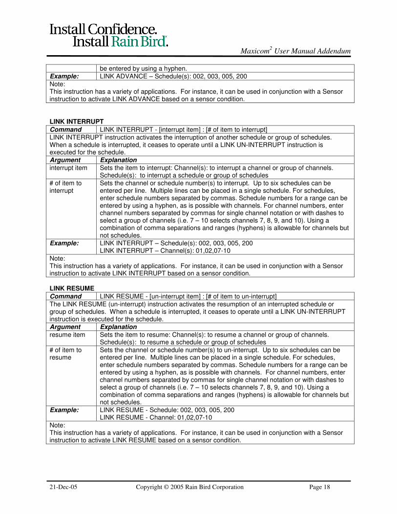
Command LINK INTERRUPT - [interrupt item] : [# of item to interrupt]
LINK INTERRUPT instruction activates the interruption of another schedule or group of schedules.When a schedule is interrupted, it ceases to operate until a LINK UN-INTERRUPT instruction isexecuted for the schedule.
Argument Explanation
interrupt item Sets the item to interrupt: Channel(s): to interrupt a channel or group of channels.Schedule(s): to interrupt a schedule or group of schedules
# of item tointerrupt
Sets the channel or schedule number(s) to interrupt. Up to six schedules can beentered per line. Multiple lines can be placed in a single schedule. For schedules,enter schedule numbers separated by commas. Schedule numbers for a range can beentered by using a hyphen, as is possible with channels. For channel numbers, enterchannel numbers separated by commas for single channel notation or with dashes toselect a group of channels (i.e. 7 – 10 selects channels 7, 8, 9, and 10). Using acombination of comma separations and ranges (hyphens) is allowable for channels butnot schedules.
Example: LINK INTERRUPT – Schedule(s): 002, 003, 005, 200LINK INTERRUPT – Channel(s): 01,02,07-10
Note:This instruction has a variety of applications. For instance, it can be used in conjunction with a Sensorinstruction to activate LINK INTERRUPT based on a sensor condition.
LINK RESUME
Command LINK RESUME - [un-interrupt item] : [# of item to un-interrupt]
The LINK RESUME (un-interrupt) instruction activates the resumption of an interrupted schedule orgroup of schedules. When a schedule is interrupted, it ceases to operate until a LINK UN-INTERRUPTinstruction is executed for the schedule.
Argument Explanation
resume item Sets the item to resume: Channel(s): to resume a channel or group of channels.Schedule(s): to resume a schedule or group of schedules
# of item toresume
Sets the channel or schedule number(s) to un-interrupt. Up to six schedules can beentered per line. Multiple lines can be placed in a single schedule. For schedules,enter schedule numbers separated by commas. Schedule numbers for a range can beentered by using a hyphen, as is possible with channels. For channel numbers, enterchannel numbers separated by commas for single channel notation or with dashes toselect a group of channels (i.e. 7 – 10 selects channels 7, 8, 9, and 10). Using acombination of comma separations and ranges (hyphens) is allowable for channels butnot schedules.
Example: LINK RESUME - Schedule: 002, 003, 005, 200LINK RESUME - Channel: 01,02,07-10
Note:This instruction has a variety of applications. For instance, it can be used in conjunction with a Sensorinstruction to activate LINK RESUME based on a sensor condition.

Maxicom2 User Manual Addendum
21-Dec-05 Copyright © 2005 Rain Bird Corporation Page 19
SENSOR COMMANDS IN SCHEDULESThere are eight commands used with sensors described in this section. These commands are:
Sensor START:Will start the schedule if a specified sensor condition is met.
Sensor INTERRUPT:Will interrupt (pause) operation while a specified sensor condition is met.
Sensor CANCEL:Will cancel the operation of a schedule when a specified sensor condition has been met.
Sensor ADVANCE:Will advance a schedule one step when a specified sensor condition has been met.
PULSE Count DownWill cause a schedule to wait for a certain number of pulses received on the specified channel beforeproceeding on to the next line of the schedule.
FLO WATCH Zone Monitor:Will monitor total water flow rate into a specific flow zone.
Flo-Zone LOG:Will cause the actual flow of water to be recorded and charted.
LOW FLOW:Will alarm if flow less than expected is detected
SEEF:Will alarm and take action if Excessive Flow is detected.
Sensor START
Command START IF - Channel[Channel #] /[Condition] {for [time] seconds (minutes)}
The Sensor START instruction allows you to begin operation of a schedule when a specified sensorcondition has been met. An optional sensitivity time can be added. This is the length of time thecondition must exist before triggering this start instruction.
Argument ExplanationChannel # Sets which channel number to monitor for the desired condition
Condition Sets the condition to look for: ON is a sensor closed or on condition, OFF is a sensoropen or off condition.
{optional} time The condition set must exist for at least the time period specified. Can be set for 1-99seconds or minutes
Example: START IF - Channel 07 /ON for 15 seconds
Note:
• For instance, this instruction may be helpful to start an irrigation schedule for a planting area if amoisture sensor condition is met.
• This will start only the current schedule. If you want to start multiple schedules, use the LINKSTART instruction.

Maxicom2 User Manual Addendum
21-Dec-05 Copyright © 2005 Rain Bird Corporation Page 20
Sensor INTERRUPT
Command INTERRUPT WHILE - Channel[Channel #] /[Condition] {for [time] seconds (minutes)}
The Sensor INTERRUPT instruction is used to cease operation while a specified sensor condition is met.The schedule will resume operation when the condition no longer exists, and will begin from the point atwhich it was originally interrupted. An optional sensitivity can be added. The sensitivity time is thelength of time the condition must exist before triggering this interrupt instruction.
Argument Explanation
Channel # Sets which channel number to monitor for the desired condition
Condition Sets the condition to look for: ON is a sensor closed or on condition, OFF is a sensoropen or off condition.
{optional} time The condition set must exist for at least the time period specified. Can be set for 1-99seconds or minutes.
Example: INTERRUPT WHILE - Channel 09 /ON for 10 minutes
Note:
• This will interrupt only the current schedule.
Sensor CANCEL
Command CANCEL IF - Channel[Channel #] /[Condition] {for [time] seconds (minutes)}
Sensor CANCEL is an instruction for a schedule to be canceled when a specified sensor condition hasbeen met. For instance, you may use this instruction to cancel an irrigation schedule if the rain sensorcondition has been met. An optional sensitivity can be added. The sensitivity time is the length of timethe condition must exist before triggering this cancel instruction.
Argument Explanation
Channel # Sets which channel number to monitor for the desired condition
Condition Sets the condition to look for: ON is a sensor closed or on condition, OFF is a sensoropen or off condition.
{optional} time The condition set must exist for at least the time period specified. Can be set for 1-99seconds or minutes.
Example: CANCEL IF - Channel 09 /ON for 10 minutes
Note:
• This will cancel only the current schedule. If you want to cancel multiple schedules or channels, usethe LINK CANCEL instruction.
Sensor ADVANCE
Command ADVANCE IF - Channel[Channel #] /[Condition] {for [time] seconds (minutes)}{delay for[time] seconds (minutes or hours)}
The Sensor ADVANCE instruction allows a schedule to advance one step in its program when aspecified sensor condition has been met. An optional sensitivity and delay time can be added.The sensitivity time is the length of time the condition must exist before triggering this advanceinstruction. The delay time is the minimum length of time that must pass between advance instructions.
Argument Explanation
Channel # Sets which channel number to monitor for the desired condition
Condition Sets the condition to look for: ON is a sensor closed or on condition, OFF is a sensoropen or off condition.
{optional} time The condition set must exist for at least the time period specified. Can be set for 1-99seconds or minutes.
{optional}delay for [time]
The delay time is the minimum interval between advances. Can be set for 0 to 99seconds or minutes, or 0-9.9 hours (prevents rapid advancing due to a singleprolonged condition)
Example: ADVANCE IF - Channel 12 /ON for 45 seconds
Note:
• This will advance only the current schedule.
Maxicom2 User Manual Addendum
21-Dec-05 Copyright © 2005 Rain Bird Corporation Page 21
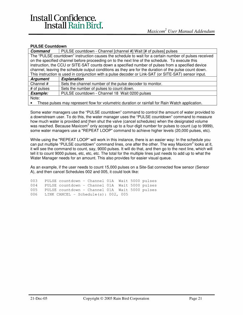
PULSE Countdown
Command PULSE countdown - Channel [channel #] Wait [# of pulses] pulses
The “PULSE countdown” instruction causes the schedule to wait for a certain number of pulses receivedon the specified channel before proceeding on to the next line of the schedule. To execute thisinstruction, the CCU or SITE-SAT counts down a specified number of pulses from a specified devicechannel, leaving the schedule output conditions as they are for the duration of the pulse count down.This instruction is used in conjunction with a pulse decoder or Link-SAT (or SITE-SAT) sensor input.
Argument Explanation
Channel # Sets the channel number of the pulse decoder to monitor.
# of pulses Sets the number of pulses to count down.
Example: PULSE countdown - Channel 18 Wait 0200 pulses
Note:
• These pulses may represent flow for volumetric duration or rainfall for Rain Watch application.
Some water managers use the “PULSE countdown” command to control the amount of water provided toa downstream user. To do this, the water manager uses the “PULSE countdown” command to measurehow much water is provided and then shut the valve (cancel schedules) when the designated volumewas reached. Because Maxicom
2 only accepts up to a four-digit number for pulses to count (up to 9999),
some water managers use a "REPEAT LOOP" command to achieve higher levels (20,000 pulses, etc).
While using the "REPEAT LOOP” will work in this instance, there is an easier way: In the schedule youcan put multiple “PULSE countdown” command lines, one after the other. The way Maxicom
2 looks at it,
it will see the command to count, say, 9000 pulses. It will do that, and then go to the next line, which willtell it to count 9000 pulses, etc, etc, etc. The total for the multiple lines just needs to add up to what theWater Manager needs for an amount. This also provides for easier visual queue.
As an example, if the user needs to count 15,000 pulses on a Site-Sat connected flow sensor (SensorA), and then cancel Schedules 002 and 005, it could look like:
003 PULSE countdown - Channel 01A Wait 5000 pulses
004 PULSE countdown - Channel 01A Wait 5000 pulses
005 PULSE countdown - Channel 01A Wait 5000 pulses
006 LINK CANCEL - Schedule(s): 002, 005
Maxicom2 User Manual Addendum
21-Dec-05 Copyright © 2005 Rain Bird Corporation Page 22
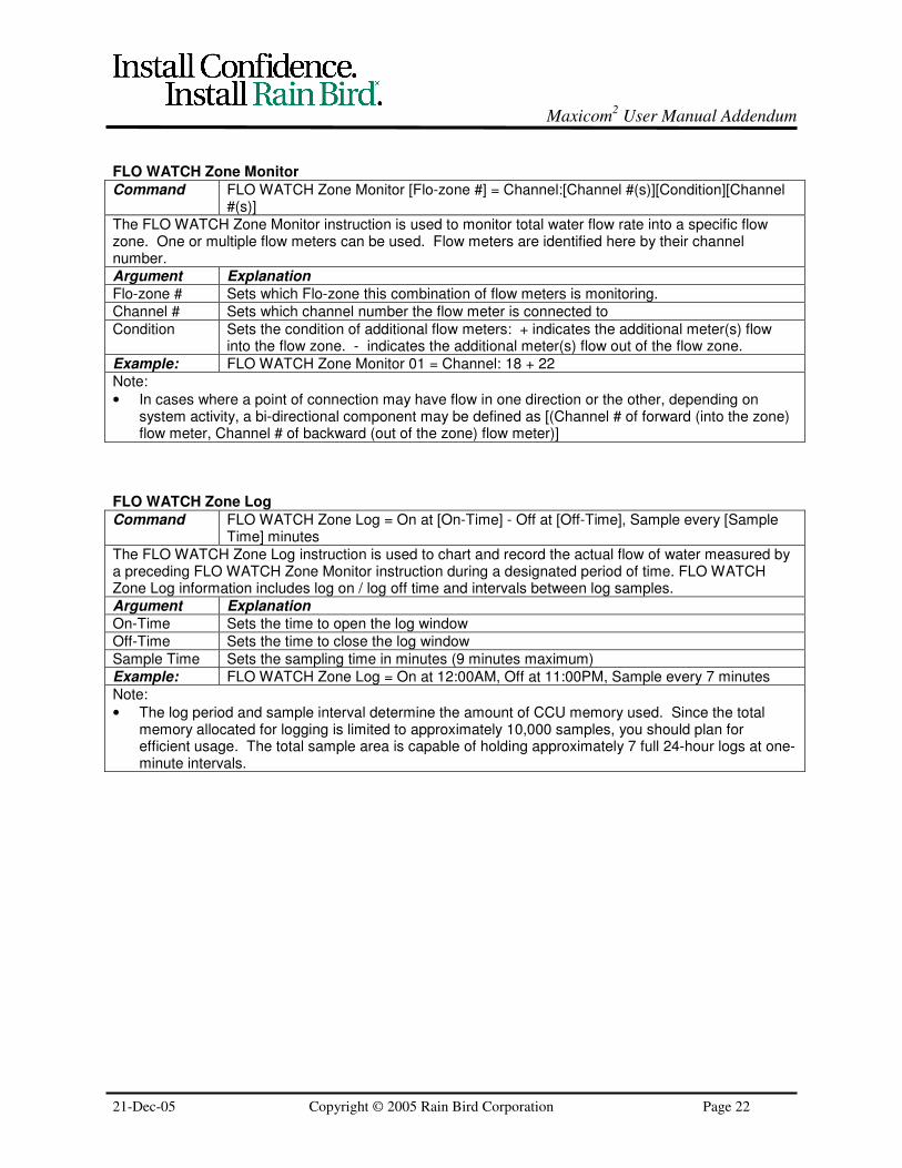
FLO WATCH Zone Monitor
Command FLO WATCH Zone Monitor [Flo-zone #] = Channel:[Channel #(s)][Condition][Channel#(s)]
The FLO WATCH Zone Monitor instruction is used to monitor total water flow rate into a specific flowzone. One or multiple flow meters can be used. Flow meters are identified here by their channelnumber.
Argument Explanation
Flo-zone # Sets which Flo-zone this combination of flow meters is monitoring.
Channel # Sets which channel number the flow meter is connected to
Condition Sets the condition of additional flow meters: + indicates the additional meter(s) flowinto the flow zone. - indicates the additional meter(s) flow out of the flow zone.
Example: FLO WATCH Zone Monitor 01 = Channel: 18 + 22
Note:
• In cases where a point of connection may have flow in one direction or the other, depending onsystem activity, a bi-directional component may be defined as [(Channel # of forward (into the zone)flow meter, Channel # of backward (out of the zone) flow meter)]
FLO WATCH Zone Log
Command FLO WATCH Zone Log = On at [On-Time] - Off at [Off-Time], Sample every [SampleTime] minutes
The FLO WATCH Zone Log instruction is used to chart and record the actual flow of water measured bya preceding FLO WATCH Zone Monitor instruction during a designated period of time. FLO WATCHZone Log information includes log on / log off time and intervals between log samples.
Argument Explanation
On-Time Sets the time to open the log window
Off-Time Sets the time to close the log window
Sample Time Sets the sampling time in minutes (9 minutes maximum)
Example: FLO WATCH Zone Log = On at 12:00AM, Off at 11:00PM, Sample every 7 minutes
Note:
• The log period and sample interval determine the amount of CCU memory used. Since the totalmemory allocated for logging is limited to approximately 10,000 samples, you should plan forefficient usage. The total sample area is capable of holding approximately 7 full 24-hour logs at one-minute intervals.

Maxicom2 User Manual Addendum
21-Dec-05 Copyright © 2005 Rain Bird Corporation Page 23
LOW FLOW
Command LOW FLOW = [deviation] times projected, settle [settling time] minutes, Fall Through[optional]
Command LOW FLOW = Detect ZERO flow only, settle [settling time] minutes, Fall Through[optional]
LOW FLOW provides alarms and fall through actions when actual flow is less than expected. LOWFLOW will operate based on information entered into the FLO WATCH data table in the Site Properties,the Flow Rate and FLO WATCH Zone data tables located in the CCU Properties, and informationentered by a preceding FLO WATCH Zone Monitor instruction. LOW FLOW will monitor the flow in aFlo-Zone and alarm if flow less than expected (dues to stuck valves, plugged heads, etc) is detected.The user can define the percentage of flow above normal (projected) flow that the system will react to,and define a settling time before alarm occurs.
The user may also (optional) define fall-through actions to occur in the event of an alarm (e.g. cancel allschedules to turn off a pump).
The User can select to alarm at a threshold below expected flow or only if “Zero Flow” (no flow). If theuser selects a threshold, they will also receive an alarm if the flow decreases to zero flow.
Argument Explanation
Deviation Sets the threshold for starting the LOW FLOW operation. This threshold is stated as amultiplier to be used for the data table entries. The deviation must be between 0.1(10% threshold) and 0.9 (90% threshold).
Settling time This is the amount of time the condition must exist before alarm. This can be setbetween 1 minute and 9 minutes
Fall Through Sets the next action to be taken when a LOW FLOW condition is found (optional). FallThrough will immediately go to and perform the next step instructions in the schedule.
Example: LOW FLOW = 0.6 times projected, Settle 5 minutes, Fall through
Example: LOW FLOW = Detect ZERO flow only, Settle 5 minutes, Fall through
Notes:
• The FLO WATCH Zone Monitor instruction must immediately precede this command.
• The Low Flow Alarm in the Event Log will include indication of active stations (stations running at thetime of the alarm) for the first five alarms.
• When the Low Flow condition clears (flow returns to a % expected rate above threshold), a warningwill be posted to the event log stating that the Low Flow Alarm Cleared.
• Important: If a Low Flow condition subsequently turns into a Zero Flow condition, a new alarm willbe posted to the event log for the Zero Flow. However, when that Zero Flow condition clears, only aZero Flow Clear warning will be posted to the event log. This is because the condition is “seen” bythe CCU as either a low flow state or a zero flow state, not both simultaneously. The Zero Flowsupercedes the Low Flow because it is more serious.
Maxicom2 User Manual Addendum
21-Dec-05 Copyright © 2005 Rain Bird Corporation Page 24
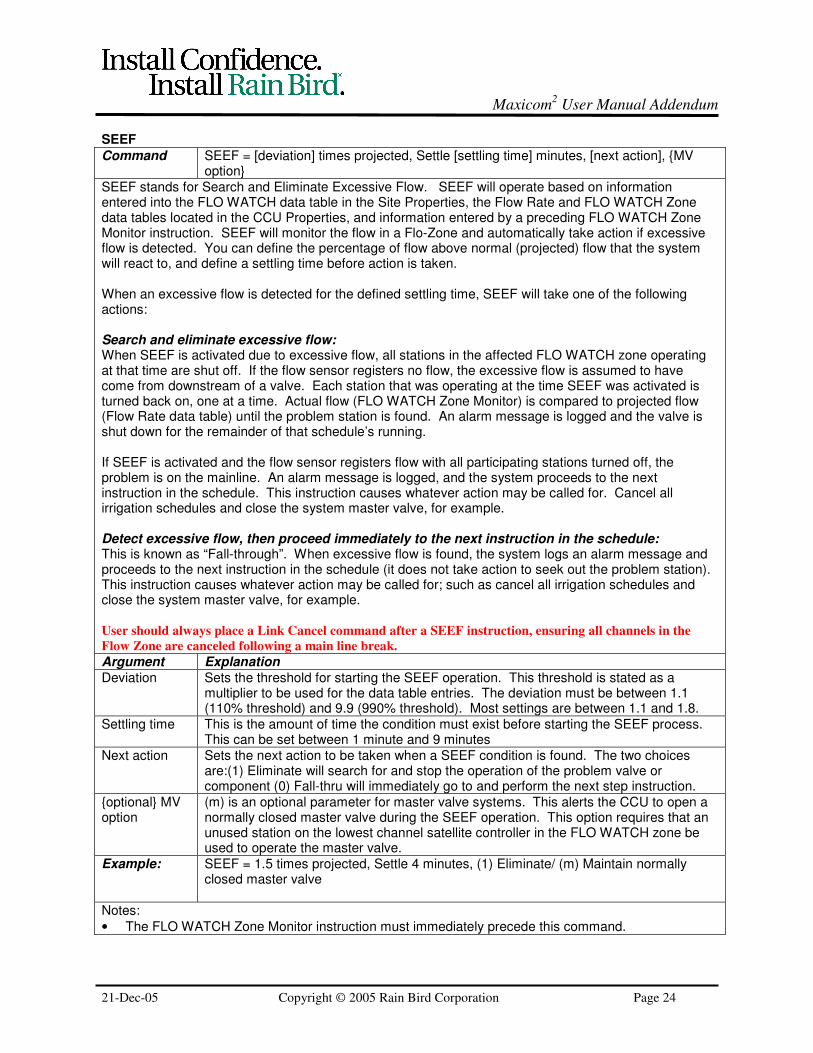
SEEF
Command SEEF = [deviation] times projected, Settle [settling time] minutes, [next action], {MVoption}
SEEF stands for Search and Eliminate Excessive Flow. SEEF will operate based on informationentered into the FLO WATCH data table in the Site Properties, the Flow Rate and FLO WATCH Zonedata tables located in the CCU Properties, and information entered by a preceding FLO WATCH ZoneMonitor instruction. SEEF will monitor the flow in a Flo-Zone and automatically take action if excessiveflow is detected. You can define the percentage of flow above normal (projected) flow that the systemwill react to, and define a settling time before action is taken.
When an excessive flow is detected for the defined settling time, SEEF will take one of the followingactions:
Search and eliminate excessive flow:When SEEF is activated due to excessive flow, all stations in the affected FLO WATCH zone operatingat that time are shut off. If the flow sensor registers no flow, the excessive flow is assumed to havecome from downstream of a valve. Each station that was operating at the time SEEF was activated isturned back on, one at a time. Actual flow (FLO WATCH Zone Monitor) is compared to projected flow(Flow Rate data table) until the problem station is found. An alarm message is logged and the valve isshut down for the remainder of that schedule’s running.
If SEEF is activated and the flow sensor registers flow with all participating stations turned off, theproblem is on the mainline. An alarm message is logged, and the system proceeds to the nextinstruction in the schedule. This instruction causes whatever action may be called for. Cancel allirrigation schedules and close the system master valve, for example.
Detect excessive flow, then proceed immediately to the next instruction in the schedule:This is known as “Fall-through”. When excessive flow is found, the system logs an alarm message andproceeds to the next instruction in the schedule (it does not take action to seek out the problem station).This instruction causes whatever action may be called for; such as cancel all irrigation schedules andclose the system master valve, for example.
User should always place a Link Cancel command after a SEEF instruction, ensuring all channels in the
Flow Zone are canceled following a main line break.
Argument Explanation
Deviation Sets the threshold for starting the SEEF operation. This threshold is stated as amultiplier to be used for the data table entries. The deviation must be between 1.1(110% threshold) and 9.9 (990% threshold). Most settings are between 1.1 and 1.8.
Settling time This is the amount of time the condition must exist before starting the SEEF process.This can be set between 1 minute and 9 minutes
Next action Sets the next action to be taken when a SEEF condition is found. The two choicesare:(1) Eliminate will search for and stop the operation of the problem valve orcomponent (0) Fall-thru will immediately go to and perform the next step instruction.
{optional} MVoption
(m) is an optional parameter for master valve systems. This alerts the CCU to open anormally closed master valve during the SEEF operation. This option requires that anunused station on the lowest channel satellite controller in the FLO WATCH zone beused to operate the master valve.
Example: SEEF = 1.5 times projected, Settle 4 minutes, (1) Eliminate/ (m) Maintain normallyclosed master valve
Notes:
• The FLO WATCH Zone Monitor instruction must immediately precede this command.
Maxicom2 User Manual Addendum
21-Dec-05 Copyright © 2005 Rain Bird Corporation Page 25
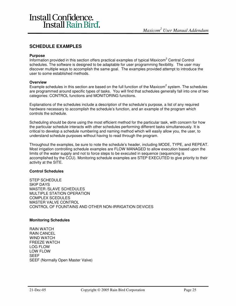
SCHEDULE EXAMPLES
PurposeInformation provided in this section offers practical examples of typical Maxicom
2 Central Control
schedules. The software is designed to be adaptable for user programming flexibility. The user maydiscover multiple ways to accomplish the same goal. The examples provided attempt to introduce theuser to some established methods.
OverviewExample schedules in this section are based on the full function of the Maxicom
2 system. The schedules
are programmed around specific types of tasks. You will find that schedules generally fall into one of twocategories: CONTROL functions and MONITORING functions.
Explanations of the schedules include a description of the schedule’s purpose, a list of any requiredhardware necessary to accomplish the schedule’s function, and an example of the program whichcontrols the schedule.
Scheduling should be done using the most efficient method for the particular task, with concern for howthe particular schedule interacts with other schedules performing different tasks simultaneously. It iscritical to develop a schedule numbering and naming method which will easily allow you, the user, tounderstand schedule purposes without having to read through the program.
Throughout the examples, be sure to note the schedule’s header, including MODE, TYPE, and REPEAT.Most irrigation controlling schedule examples are FLOW MANAGED to allow execution based upon thelimits of the water supply and not to force steps to be executed in sequence (sequencing isaccomplished by the CCU). Monitoring schedule examples are STEP EXECUTED to give priority to theiractivity at the SITE.
Control Schedules
STEP SCHEDULESKIP DAYSMASTER /SLAVE SCHEDULESMULTIPLE STATION OPERATIONCOMPLEX SCEDULESMASTER VALVE CONTROLCONTROL OF FOUNTAINS AND OTHER NON-IRRIGATION DEVICES
Monitoring Schedules
RAIN WATCHRAIN CANCELWIND WATCHFREEZE WATCHLOG FLOWLOW FLOWSEEFSEEF (Normally Open Master Valve)

Maxicom2 User Manual Addendum
21-Dec-05 Copyright © 2005 Rain Bird Corporation Page 26
Note: Comments in Maxicom2 Schedules
When programming schedules in Maxicom2, it is possible to place a comment in the schedule (to explain
a step, etc) by placing an asterisk (*) before the comment. Remember, however, that comments are notsupposed to be on the same line as instructions. Maxicom
2 does not prevent this like MAXICOM for DOS
did, so users may assume it is okay. Comments should always be on a separate line.
Incorrect:Station 07, 060 Minutes *Blue flowers by east door
Correct:Station 07, 060 Minutes*Blue flowers by east door
If the comment is written on the same line, Maxicom2 may interpret it as some form of command,depending on what characters are used (e.g. an “x” on the same line as the command above is believedto cancel the runtime and make the command ET-adjusted).
Note: Design of Schedule Examples to Follow
The schedule examples that follow are examples of “one way” to do things. They are not meant as the“only way” to do things. Most of the examples show status for Flo-Manager, ET, Water Budget, RuntimeAdjustment, etc. These variables are user set and what is listed in the example is not always “required”.For example, many users do not Flo-Manage Link Schedules because they are building their own Flo-Management routine using multiple Link Schedules. However, many of the examples show LinkSchedules as “Flo-Managed.”
Where a setting is required, there should be a note in the “Program” section of the example summary.

Maxicom2 User Manual Addendum
21-Dec-05 Copyright © 2005 Rain Bird Corporation Page 27
CONTROL SCHEDULES
Step Schedule ExecutionPurpose: To operate a schedule in the sequence programmed, STEP-EXECUTED scheduling is
utilized. The full function of Maxicom2 can best be achieved by utilizing FLO-
MANAGED schedules for all irrigation schedules and using STEP-EXECUTEDschedules for monitoring functions, master schedules, and non-irrigation schedules. Itis important to note that STEP schedules take priority over FLO-MANAGED schedules.
Hardware: No special hardware required
Program: Programming a STEP schedule simply requires making the schedule NOT FLO-MANAGED.
Irrigation Scheduling by Odd-Even patternsPurpose: Irrigation sometimes requires the use of a Odd or Even day pattern. Scheduling by
Odd/Even allows the system to decide which days to water on based on whether thecalendar day is odd or even.
Hardware: No special hardware required. Maxicom2 Version 3.0 required.
Program: For odd/even patterns the START DAYS will be designated as ODD Days, EVENDays, or ODD31 Days (odd days with the exception of the 31
st in 31-day months).
These schedules also have an option to “exclude” days of the week. Excluded days areset either in the Start Days wizard in Schedule Editor or on the Schedule PropertiesTab in Schedule Editor. This feature allows Start Days to be set as (for example) OddDays with the exception of Sunday. (Do not water on Sunday even if it is an odd day.)
Schedule: Odd31 DaysSite: Example
Schedule Number: 020 Programmed Repeats: 0 FLO-MANAGER: YESAutomatic Send: YES Protected: NO Runtime Adjustment: Site ETNominal ET: 0.10 in/d
001 START ON – ODD31 Days
002 START AT – 12:00AM
003 Ms4 Satellite CHANNEL – 01
004 Station 01, Calculated
005 Station 05, Calculated
NOTE: In “Schedule Monitoring” of the “Manual Site Operations” screen (when manually contacting aCCU), an Odd/Even/Odd31 schedule will display the start days for the next seven days as days of theweek (Monday, Tuesday, etc). Because of the way Maxicom
2 displays Start Days, these days will not be
in chronological order for the next seven days, but listed based on a SuMTuWThFSa ordering. ForExample, if it is Thursday and Start Days in the next seven days are Friday (tomorrow) and Tuesday (ofnext week), you will see it listed in Schedule Monitoring as:
001 START ON – TUESDAY FRIDAY
Maxicom2 User Manual Addendum
21-Dec-05 Copyright © 2005 Rain Bird Corporation Page 28
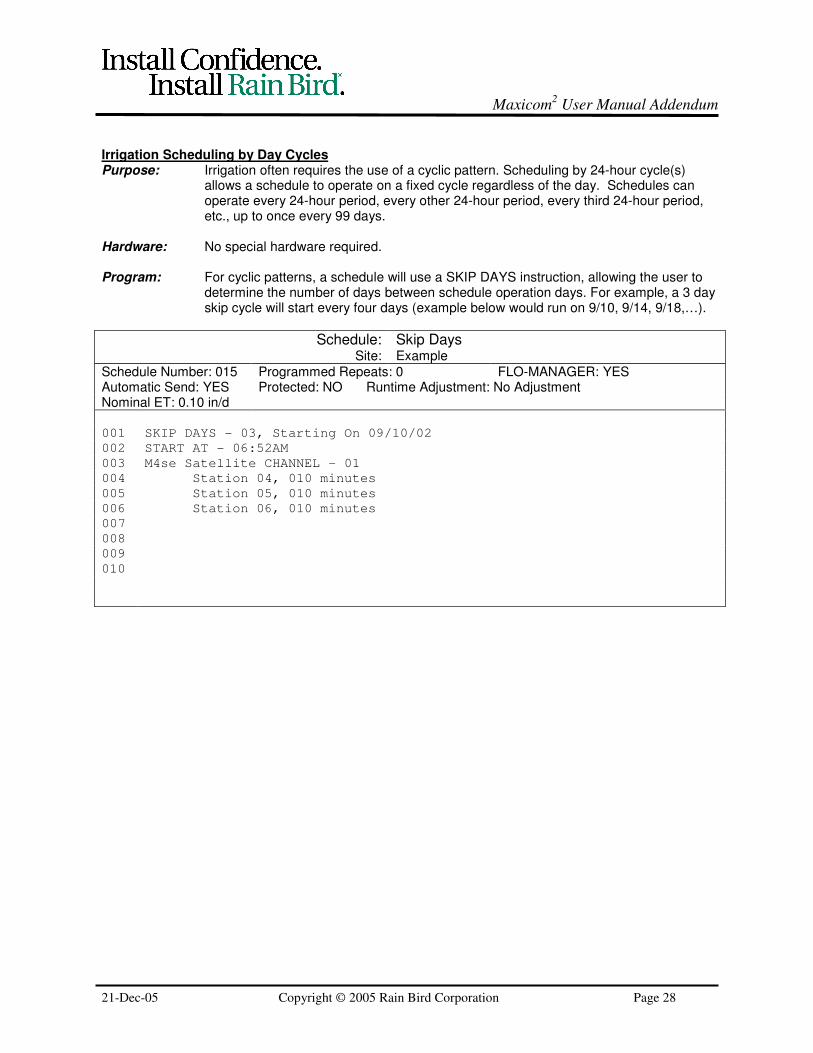
Irrigation Scheduling by Day CyclesPurpose: Irrigation often requires the use of a cyclic pattern. Scheduling by 24-hour cycle(s)
allows a schedule to operate on a fixed cycle regardless of the day. Schedules canoperate every 24-hour period, every other 24-hour period, every third 24-hour period,etc., up to once every 99 days.
Hardware: No special hardware required.
Program: For cyclic patterns, a schedule will use a SKIP DAYS instruction, allowing the user todetermine the number of days between schedule operation days. For example, a 3 dayskip cycle will start every four days (example below would run on 9/10, 9/14, 9/18,…).
Schedule: Skip DaysSite: Example
Schedule Number: 015 Programmed Repeats: 0 FLO-MANAGER: YESAutomatic Send: YES Protected: NO Runtime Adjustment: No AdjustmentNominal ET: 0.10 in/d
001 SKIP DAYS - 03, Starting On 09/10/02
002 START AT - 06:52AM
003 M4se Satellite CHANNEL – 01
004 Station 04, 010 minutes
005 Station 05, 010 minutes
006 Station 06, 010 minutes
007
008
009
010
Maxicom2 User Manual Addendum
21-Dec-05 Copyright © 2005 Rain Bird Corporation Page 29
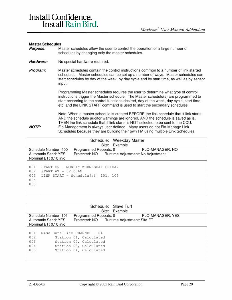
Master SchedulesPurpose: Master schedules allow the user to control the operation of a large number of
schedules by changing only the master schedules.
Hardware: No special hardware required.
Program: Master schedules contain the control instructions common to a number of link startedschedules. Master schedules can be set up a number of ways. Master schedules canstart schedules by day of the week, by day cycle and by start time, as well as by sensorinput.
Programming Master schedules requires the user to determine what type of controlinstructions trigger the Master schedule. The Master schedule(s) are programmed tostart according to the control functions desired, day of the week, day cycle, start time,etc. and the LINK START command is used to start the secondary schedules.
Note: When a master schedule is created BEFORE the link schedule that it link starts,AND the schedule auditor warnings are ignored, AND the schedule is saved as is,THEN the link schedule that it link starts is NOT selected to be sent to the CCU.
NOTE: Flo-Management is always user defined. Many users do not Flo-Manage LinkSchedules because they are building their own FM using multiple Link Schedules.
Schedule: Weekday MasterSite: Example
Schedule Number: 400 Programmed Repeats: 0 FLO-MANAGER: NOAutomatic Send: YES Protected: NO Runtime Adjustment: No AdjustmentNominal ET: 0.10 in/d
001 START ON – MONDAY WEDNESDAY FRIDAY
002 START AT - 02:00AM
003 LINK START – Schedule(s): 101, 105
004
005
Schedule: Slave TurfSite: Example
Schedule Number: 101 Programmed Repeats: 0 FLO-MANAGER: YESAutomatic Send: YES Protected: NO Runtime Adjustment: Site ETNominal ET: 0.10 in/d
001 M4se Satellite CHANNEL - 04
002 Station 01, Calculated
003 Station 02, Calculated
004 Station 03, Calculated
005 Station 04, Calculated
Maxicom2 User Manual Addendum
21-Dec-05 Copyright © 2005 Rain Bird Corporation Page 30
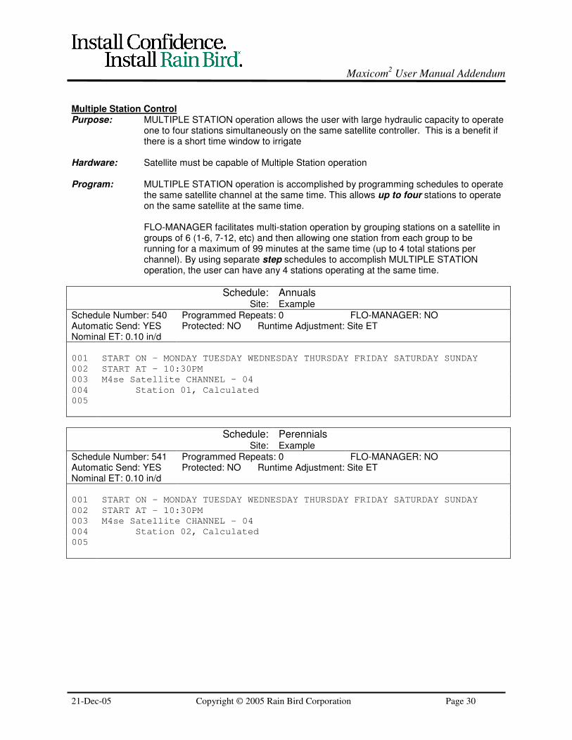
Multiple Station ControlPurpose: MULTIPLE STATION operation allows the user with large hydraulic capacity to operate
one to four stations simultaneously on the same satellite controller. This is a benefit ifthere is a short time window to irrigate
Hardware: Satellite must be capable of Multiple Station operation
Program: MULTIPLE STATION operation is accomplished by programming schedules to operatethe same satellite channel at the same time. This allows up to four stations to operateon the same satellite at the same time.
FLO-MANAGER facilitates multi-station operation by grouping stations on a satellite ingroups of 6 (1-6, 7-12, etc) and then allowing one station from each group to berunning for a maximum of 99 minutes at the same time (up to 4 total stations perchannel). By using separate step schedules to accomplish MULTIPLE STATIONoperation, the user can have any 4 stations operating at the same time.
Schedule: AnnualsSite: Example
Schedule Number: 540 Programmed Repeats: 0 FLO-MANAGER: NOAutomatic Send: YES Protected: NO Runtime Adjustment: Site ETNominal ET: 0.10 in/d
001 START ON – MONDAY TUESDAY WEDNESDAY THURSDAY FRIDAY SATURDAY SUNDAY
002 START AT – 10:30PM
003 M4se Satellite CHANNEL – 04
004 Station 01, Calculated
005
Schedule: PerennialsSite: Example
Schedule Number: 541 Programmed Repeats: 0 FLO-MANAGER: NOAutomatic Send: YES Protected: NO Runtime Adjustment: Site ETNominal ET: 0.10 in/d
001 START ON – MONDAY TUESDAY WEDNESDAY THURSDAY FRIDAY SATURDAY SUNDAY
002 START AT – 10:30PM
003 M4se Satellite CHANNEL – 04
004 Station 02, Calculated
005

Maxicom2 User Manual Addendum
21-Dec-05 Copyright © 2005 Rain Bird Corporation Page 31
Schedule: ShrubsSite: Example
Schedule Number: 542 Programmed Repeats: 0 FLO-MANAGER: NOAutomatic Send: YES Protected: NO Runtime Adjustment: Site ETNominal ET: 0.10 in/d
001 START ON – MONDAY TUESDAY WEDNESDAY THURSDAY FRIDAY SATURDAY SUNDAY
002 START AT – 10:30PM
003 M4se Satellite CHANNEL – 04
004 Station 03, Calculated
005

Maxicom2 User Manual Addendum
21-Dec-05 Copyright © 2005 Rain Bird Corporation Page 32
Complex Schedule Cycles (Every Third Day, Excluding Sundays)Purpose: A combination of schedules can allow a user to irrigate complex cycles otherwise
impossible with a simple SKIP DAYS command. An example would be irrigating everythird day, with the exception of Sundays.
Hardware: No special hardware required.
Program: Third-day irrigation with the exception of Sundays is accomplished with a combinationof schedules:
SKIP DAYS (015) - A typical irrigation schedule set for a SKIP DAYS cycle. In order tocancel this schedule on Sundays and make sure that no irrigation occurs, the PAUSEFOR – 02 Minutes command must be entered prior to the channel and stationinstructions.
CANCEL SPECIFIC DAY (016) – A schedule to cancel the SKIP DAYS schedule onSundays. This schedule must be set to run continuously in the schedule properties.You must have all schedules that would possibly run entered into the LINK CANCELcommand (example: 015). If the schedule you are canceling is Flo-Managed, you mustcancel the channel (cancelling the schedule will not cancel times posted to the runtimeroster).
CANCEL DAY CANCEL (017) – A schedule to cancel the first LINK CANCEL scheduleat the end of Sunday. Since schedule 016 is set for continuous operation, you musthave a second schedule that will stop/ cancel schedule 016 at the end of Sunday.
Schedule: Skip DaysSite: Example
Schedule Number: 015 Programmed Repeats: 0 FLO-MANAGER: NOAutomatic Send: YES Protected: NO Runtime Adjustment: No AdjustmentNominal ET: 0.10 in/d
001 SKIP DAYS – 02, Starting On 10/1/02
002 START AT – 06:50AM
003 PAUSE FOR – 02 minutes
004 M4se Satellite CHANNEL - 01
005 Station 04, 010 minutes
006 Station 05, 010 minutes
007 Station 06, 010 minutes
Schedule: Cancel Specific DaySite: Example
Schedule Number: 016 Programmed Repeats: Continuously FLO-MANAGER: NOAutomatic Send: YES Protected: NO Runtime Adjustment: Site ETNominal ET: 0.10 in/d
001 START ON – SUNDAY
002 START AT – 12:00AM
003 LINK CANCEL – Schedule(s): 015
004 PAUSE FOR – 01 minutes

Maxicom2 User Manual Addendum
21-Dec-05 Copyright © 2005 Rain Bird Corporation Page 33
Schedule: Cancel Day CancelSite: Example
Schedule Number: 017 Programmed Repeats: 0 FLO-MANAGER: NOAutomatic Send: YES Protected: NO Runtime Adjustment: No AdjustmentNominal ET: 0.10 in/d
001 START ON – SUNDAY
002 START AT – 11:55PM
003 LINK CANCEL – Schedule(s): 016
004
005

Maxicom2 User Manual Addendum
21-Dec-05 Copyright © 2005 Rain Bird Corporation Page 34
Master Valve ControlPurpose: To turn on a Master Valve whenever a selected satellite listed is on.
Hardware: Normally Closed Master Valve.
Program: Station 24 of the lowest channel number in the “Flow Zone” of the master valve(Channel 2 in example below) must be blank (i.e No valve, decoder, etc connected toit), and the Normally Closed Master Valve wired to the Master Valve Circuit of thatchannels Satellite Controller.
Master Valve On (903)START IF schedule to open Master Valve for selected satellite (in example below, theMaster Valve on channel 2 also provides water for channel 4 stations) - Provideenough time to avoid cycling.
Master Valve Off (904)Cancels Master Valve On schedule whenever selected satellites are off. START IFcommand starts schedule if the selected channels are off. PAUSE command to avoidturning off Master Valve too soon. LINK CANCEL command cancels Master Valve Onschedule (turns off Master Valve) since all satellites are off.
Caution should be used with these schedules. Timing used here may not be bestfor all systems. User should test and adjust to their equipment.
Schedule: Master Valve OnSite: Example
Schedule Number: 903 Programmed Repeats: 0 FLO-MANAGER: NOAutomatic Send: YES Protected: NO Runtime Adjustment: No AdjustmentNominal ET: 0.10 in/d
001 START IF – Channel 04 /ON for 2 seconds
002 Ms4 Satellite CHANNEL – 02
003 Station 24, 12 hours /Park
004
005
Schedule: Master Valve OffSite: Example
Schedule Number: 904 Programmed Repeats: 0 FLO-MANAGER: NOAutomatic Send: YES Protected: NO Runtime Adjustment: No AdjustmentNominal ET: 0.10 in/d
001 START IF – Channel 04 /OFF for 10 seconds
002 PAUSE FOR – 05 seconds
003 LINK CANCEL – Schedule(s): 903
004
005

Maxicom2 User Manual Addendum
21-Dec-05 Copyright © 2005 Rain Bird Corporation Page 35
Control of Fountains and Other Non-Irrigation DevicesPurpose: Maxicom
2 can control fountains, security gates, or other non-irrigation devices with
some simple programming. The user can also program other monitoring functions toturn on or off these peripheral devices.
The method used allows a satellite controller to operate a 24VAC relay with the stationoutput from the satellite. Multiple station operation is required for this scenario to workwith non-irrigation devices, which need to operate simultaneously with other activities.
Hardware: Satellite controller with available stations to control the relayRelay (24 VAC Holding coil/ 0.15 amp maximum)
Program: Two schedules are used to turn the lights on/off.
Schedules to control non-irrigation devices should be step schedules with noRuntime Adjustment.
Schedule: Lights OnSite: Ballfield
Schedule Number: 601 Programmed Repeats: 0 FLO-MANAGER: NOAutomatic Send: YES Protected: YES Runtime Adjustment: No AdjustmentNominal ET: 0.10 in/d
001 START ON – MONDAY TUESDAY WEDNESDAY THURSDAY FRIDAY SATURDAY SUNDAY
002 START AT - 06:00PM
003 Ms4 Satellite CHANNEL – 01
004 Station 01, 001 minutes
005
Schedule: Lights OffSite: Ballfield
Schedule Number: 602 Programmed Repeats: 0 FLO-MANAGER: NOAutomatic Send: YES Protected: YES Runtime Adjustment: No AdjustmentNominal ET: 0.10 in/d
001 START ON – MONDAY TUESDAY WEDNESDAY THURSDAY FRIDAY SATURDAY SUNDAY
002 START AT - 10:30PM
003 Ms4 Satellite CHANNEL – 01
004 Station 02, 001 minutes
005

Maxicom2 User Manual Addendum
21-Dec-05 Copyright © 2005 Rain Bird Corporation Page 36
MONITORING SCHEDULES
For weather sensor schedules (Rain Watch, Wind Watch, etc), the schedule can be written to "Interrupt,""Resume," or "Cancel" either schedules or channels (affects all irrigation for the Satellite assigned to thatchannel of the CCU).
The "INTERRUPT" command will pause irrigation on the indicated schedule or channel, usually to waitand see if the weather condition persists.
The "RESUME" command will restart irrigation, usually if the condition does not persist
The "CANCEL" command will completely cancel irrigation for the designated schedule or channel for therest of the irrigation day. It does not allow irrigation to "RESUME."
Rain Watch (reaction to rain at the site)Purpose: RAIN WATCH causes active channels listed in the schedule to interrupt if rainfall
occurs and cancels irrigation if it reaches a pre-determined amount.
Hardware: Rainfall Gauge - Rain Bird Model RAINGAUGE.Pulse Decoder (DECPUL) if Two-Wire System
Program: The RAIN WATCH function is accomplished using three separate schedules:
RAIN WATCH schedule monitors the Rain Gauge to trigger the INTERRUPTinstruction. The LINK START is used to start a secondary schedule. The examplebelow is based on a Two-Wire system. Because of Satellite Polling functions in aMAXILink System, the “for 15 seconds” caveat in the START IF command would not beused.
The secondary schedule (RAIN COUNT) begins with a PULSE COUNTDOWN todetermine if enough rainfall occurs to cancel irrigation. If desired count is attainedwithin the time allotted by RAIN WATCH schedule (PAUSE FOR instruction) then thetertiary schedule RAIN INHIBIT is started to cancel irrigation (runs continuously).Otherwise, RAIN WATCH will resume irrigation.
If Rain Watch is to interrupt a Flo-Managed schedule, the command mustinterrupt the channel. If it is a step schedule (as per below example) then youwould affect the schedule.
Schedule: Irrigation Example (Step Schedule)Site: Example
Schedule Number: 105 Programmed Repeats: 0 FLO-MANAGER: NoAutomatic Send: YES Protected: NO Runtime Adjustment: No AdjustmentNominal ET: 0.10 in/d
001 START ON – MONDAY TUESDAY WEDNESDAY THURSDAY FRIDAY SATURDAY SUNDAY
002 START AT – 12:30AM
003 Ms4 Satellite Channel – 05
004 Station 01, 020 minutes
005
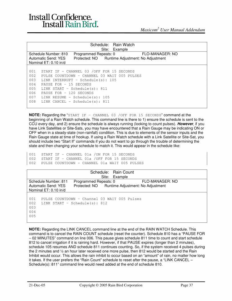
Maxicom2 User Manual Addendum
21-Dec-05 Copyright © 2005 Rain Bird Corporation Page 37
Schedule: Rain WatchSite: Example
Schedule Number: 810 Programmed Repeats: 0 FLO-MANAGER: NOAutomatic Send: YES Protected: NO Runtime Adjustment: No AdjustmentNominal ET: 0.10 in/d
001 START IF – CHANNEL 03 /OFF FOR 15 SECONDS
002 PULSE COUNTDOWN – CHANNEL 03 WAIT 005 PULSES
003 LINK INTERRUPT – Schedule(s): 105
004 PAUSE FOR – 15 SECONDS
005 LINK START – Schedule(s): 811
006 PAUSE FOR – 120 SECONDS
007 LINK RESUME – Schedule(s): 105
008 LINK CANCEL – Schedule(s): 811
NOTE: Regarding the “START IF – CHANNEL 03 /OFF FOR 15 SECONDS” command at the
beginning of a Rain Watch schedule. This command line is there to 1) ensure the schedule is sent to theCCU every day, and 2) ensure the schedule is always running (looking to count pulses). However, if youhave Link Satellites or Site-Sats, you may have encountered that a Rain Gauge may be indicating ON orOFF when in a steady-state (non-rainfall) condition. This is due to elements of the sensor inputs and theRain Gauge state at time of hookup. If using a Rain Watch schedule with a Link Satellite or Site-Sat, youshould include two “Start If” commands if you do not want to go through the trouble of determining thestate and then changing your schedule to match it. This would appear in the schedule like:
001 START IF – CHANNEL 01a /ON FOR 15 SECONDS
002 START IF – CHANNEL 01a /OFF FOR 15 SECONDS
002 PULSE COUNTDOWN – CHANNEL 01a WAIT 005 PULSES
Schedule: Rain CountSite: Example
Schedule Number: 811 Programmed Repeats: 0 FLO-MANAGER: NOAutomatic Send: YES Protected: NO Runtime Adjustment: No AdjustmentNominal ET: 0.10 in/d
001 PULSE COUNTDOWN – Channel 03 WAIT 005 Pulses
002 LINK START – Schedule(s): 812
003
004
005
NOTE: Regarding the LINK CANCEL command line at the end of the RAIN WATCH Schedule. Thiscommand is to cancel the RAIN COUNT schedule (reset the counter). Schedule 810 has a “PAUSE FOR– 02 MINUTES” command on line 006. This pause gives schedule 811 time to count and start schedule812 to cancel irrigation if it is raining hard. However, if that PAUSE expires (longer than 2 minutes),schedule 105 resumes AND schedule 811 continues counting. So, if the system received 4 pulses duringthe 2 minutes and ½ an hour later received one more pulse, then 812 would be started and the RainInhibit would occur. This allows the rain inhibit to occur based on an “amount” of rain, no matter how longit takes. If the user prefers the “Rain Count” schedule to reset after the pause, a “LINK CANCEL –Schedule(s): 811” command line would need added at the end of schedule 810.

Maxicom2 User Manual Addendum
21-Dec-05 Copyright © 2005 Rain Bird Corporation Page 38
Schedule: Rain InhibitSite: Example
Schedule Number: 812 Programmed Repeats: Continuous FLO-MANAGER: NOAutomatic Send: YES Protected: NO Runtime Adjustment: No AdjustmentNominal ET: 0.10 in/d
001 LINK CANCEL – Schedule(s): 105, 810
002 LINK Cancel – Channel(s): 05
003 PAUSE FOR – 59 seconds
004
005
NOTE: This RAIN INHIBIT program uses continuous repeats and a 59 second pause to ensure that isanything starts, it is cancelled within 1 minute after start.
Rain Cancel (Cancel irrigation if rain detected)Purpose: RAIN CANCEL stops irrigation if a rain shut off device is used (instead of a Rain
Gauge, which can measure rainfall amount).
Hardware: Switch-Type Rain SensorRain Bird Sensor Decoder (DECSEN M51300) – If Two-Wire system
Program: The RAIN CANCEL function is accomplished using a LINK CANCEL if rain is detected.
Schedule: Rain CancelSite: Example
Schedule Number: 701 Programmed Repeats: 0 FLO-MANAGER: NOAutomatic Send: YES Protected: YES Runtime Adjustment: No AdjustmentNominal ET: 0.10 in/d
001 START IF – CHANNEL 03 /OFF FOR 30 SECONDS
002 LINK CANCEL – Channel(s): 01
003 LINK CANCEL – Schedule(s): 100
004
005

Maxicom2 User Manual Addendum
21-Dec-05 Copyright © 2005 Rain Bird Corporation Page 39
Wind Watch (reaction to wind at the site)Purpose: WIND WATCH causes active channels listed on the schedule to interrupt if wind
reached a pre-determined speed and cancels irrigation if this speed is sustained.Prevents wasted water due to improper distribution, misting, etc.
Hardware: Anemometer (Wind Speed Sensor) - Rain Bird Model ANEMOMETER.Pulse Transmitter (PT322 or PT1502)Rain Bird Pulse Decoder (DECPUL M51200) – Unless Link Satellite
Program: The WIND WATCH function is accomplished using three separate schedules: WINDWATCH schedule monitors the Anemometer to trigger the INTERRUPT instruction. APAUSE instruction allows for the INTERRUPT to be carried out. The LINK START isused to start a secondary schedule.
The secondary schedule (WIND COUNT) begins with a PULSE COUNTDOWN todetermine if Wind Speed is sustained. If desired count is attained within the timeallotted by WIND WATCH schedule (PAUSE FOR instruction) then the tertiaryschedule WIND INHIBIT is started to cancel irrigation. Otherwise, WIND WATCH willresume irrigation and cancel the WIND COUNT schedule (resets the counting).
These schedules must be Step Type.
The following instruction explains how to properly program a Pulse Transmitter and the Maxicom2
Software in order to use an Anemometer (Wind Speed Sensor) to “inhibit” (cancel) irrigation due to highwinds.
For the Pulse Transmitter (PT322 or PT1502) Programming:1) Select “Wind Speed Sensor (WSS)” as your “Irrigation Sensor Type”2) Leave the K and Offset values as the software shows, as well as what the pulse width indicates.
These values are:K Factor = 1.696500Offset = 0.059000Pulse width = 100ms
3) Set the Units of measure as miles/hr or km/hr (metric). The rest of this guide references miles perhour.
4) For the pulse equivalent setting, the following is an example of what the setting means:
1 Pulse = 1.000000 PPM per mile/hour
This means: 1 Pulse output by the Pulse Transmitter (e.g. PT322) is the equivalent of 1.000000Pulse Per Minute (PPM) for every 1-mile/hr-wind speed. That is, if the CCU receives 1 pulse in 1minute, the wind speed is 1 mile/hr. If it receives 2 pulses in 1 minute, it is 2 miles/hr.
For the Sensor Settings in CCU Properties (miles per pulse): This setting has no effect on WINDWATCH programming. It is a setting more appropriate for "Wind Logging". For Wind Watch, the CCU iscounting pulses. So, set this variable as 1 mile/pulse and ignore it for the purposes of Wind Watch.
NOTE: If you will be doing wind logging, it must be noted that there is an inability to set a value less than0.5 miles per pulse for Two-Wire pulse decoders and the setting will be rounded to a whole numberwhen it is sent to the CCU. So, for Wind Logging, it is recommended that the user set the PT322 to avalue that is a whole number of PPM per mile/hr.

Maxicom2 User Manual Addendum
21-Dec-05 Copyright © 2005 Rain Bird Corporation Page 40
When writing the Wind Watch schedule, set the "PAUSE FOR" long enough to get enough pulses to beequivalent to your Wind Setpoint based on what you set in the PT322 and then count this number ofpulses in the Wind Count schedule.
For Example (Wind Inhibit at 60 miles/hr):
IF you set 1 Pulse = 0.050000 PPM per mile/hr in the PT322, AND, you want the Wind Inhibit activatedat 60 miles/hr, THEN you could PAUSE FOR – 300 Seconds and PULSE COUNTDOWN 15 pulses.
0.050000 PPM per mile/hr Desired speed TIME FOR pulsecountdown
0.050000 Pulses hour 60 miles 5 minutes = 15 pulses
1 Minute 1 mile hour
So, adjust these variables until you get what you want. It is recommended that the user sets a TIMEFOR setting of a couple minutes in order to ensure that canceling irrigation is due to sustained winds andnot just reaction to a gust.
The following schedule examples assume these same settings.
Schedule: Wind WatchSite: Example
Schedule Number: 801 Programmed Repeats: 0 FLO-MANAGER: NOAutomatic Send: YES Protected: NO Runtime Adjustment: No AdjustmentNominal ET: 0.10 in/d
001 START IF – CHANNEL 03 /OFF FOR 5 seconds
002 PULSE COUNTDOWN – CHANNEL 03 WAIT 006 pulses
003 LINK INTERRUPT – Schedule(s): 101, 102, 103, 201, 202, 203
004 PAUSE FOR – 05 seconds
005 LINK START – schedule(s): 802
006 PAUSE FOR – 300 seconds
007 LINK RESUME – schedule(s): 101, 102, 103, 201, 202, 203
008 LINK CANCEL – schedule(s): 802
009
NOTE: It is recommended that the PAUSE FOR commands use seconds instead of minutes to ensure afull counting period once the WIND COUNT schedule is started.
Schedule: Wind CountSite: Example
Schedule Number: 802 Programmed Repeats: 0 FLO-MANAGER: NOAutomatic Send: YES Protected: NO Runtime Adjustment: No AdjustmentNominal ET: 0.10 in/d
001 PULSE COUNTDOWN – Channel 03 WAIT 015 Pulses
002 LINK START – SCHEDULE(S): 803
003
004
005

Maxicom2 User Manual Addendum
21-Dec-05 Copyright © 2005 Rain Bird Corporation Page 41
Schedule: Wind InhibitSite: Example
Schedule Number: 803 Programmed Repeats: Continuous FLO-MANAGER: NOAutomatic Send: YES Protected: NO Runtime Adjustment: No AdjustmentNominal ET: 0.10 in/d
001 LINK CANCEL – Channel(s): 01, 04, 05
002 LINK CANCEL – Schedule(s): 101, 102, 103, 201, 202, 203
003 LINK CANCEL – Schedule (s): 801
004 PAUSE FOR – 59 seconds
005
NOTE: Setting the programmed repeats as “Continuous” and having a PAUSE FOR 59 seconds ensuresno schedules will run for the irrigation evening. Any new schedules would try to start at the top of aminute and the WIND INHIBIT schedule is repeatedly canceling everything at a frequency less than aminute.
NOTE: If you do not want irrigation cancelled for the rest of the irrigation day, you will need to set up adifferent schedule format than the “continuous repeat” format of 803.

Maxicom2 User Manual Addendum
21-Dec-05 Copyright © 2005 Rain Bird Corporation Page 42
Freeze Watch (reaction to temperature at the site)Purpose: FREEZE WATCH causes active channels listed on the schedule to interrupt when a
freeze sensor drops below its set point. Channel activity resumes once temperaturerises above the set point.
Hardware: Switch-Type Freeze Sensor (similar to Glen-Hilton Freeze-Clik, Model 401)Rain Bird Sensor Decoder (DECSEN M51300)
Program: The FREEZE WATCH function is accomplished using three separate schedules.
The primary schedule (906) contains a START IF instruction to monitor thetemperature sensor to trigger the INTERRUPT instruction. A PAUSE instruction on thenext line allows time for the prior instruction to be carried out. The LINK STARTinstruction is then used to start a secondary schedule. The secondary schedule (907)begins with a PAUSE, then cycles continuously over the LINK RESUME, PAUSE, andLINK START until the freeze sensor reports temperatures above the thresholdcondition. Temperatures above freezing will cause the primary schedule to switch OFFand the secondary schedule to execute the three steps it has been skipping over (LINKRESUME, PAUSE, and LINK START the final schedule). The final schedule (908) usesPAUSE and LINK CANCEL to stop the cycling of the secondary schedule.
These schedules must be Step Type
Schedule: Irrigation ExampleSite: Example
Schedule Number: 106 Programmed Repeats: 0 FLO-MANAGER: NoAutomatic Send: YES Protected: NO Runtime Adjustment: No AdjustmentNominal ET: 0.10 in/d
001 START ON – MONDAY TUESDAY WEDNESDAY THURSDAY FRIDAY
002 START AT – 12:30AM
003 Ms4 Satellite Channel – 06
004 Station 05, 020 minutes
005
Schedule: Freeze WatchSite: Example
Schedule Number: 906 Programmed Repeats: 0 FLO-MANAGER: NOAutomatic Send: YES Protected: NO Runtime Adjustment: No AdjustmentNominal ET: 0.10 in/d
001 START IF – CHANNEL 04 /ON FOR 30 SECONDS
002 LINK INTERRUPT – Schedule(s): 106
003 PAUSE FOR - 15 seconds
004 LINK START - Schedule(s): 907
005

Maxicom2 User Manual Addendum
21-Dec-05 Copyright © 2005 Rain Bird Corporation Page 43
Schedule: Freeze ResetSite: Example
Schedule Number: 907 Programmed Repeats: Continuous FLO-MANAGER: NOAutomatic Send: YES Protected: NO Runtime Adjustment: No AdjustmentNominal ET: 0.10 in/d
001 SKIP next – 03 Steps / Channel 04 / ON
002 LINK RESUME – Schedule(s): 106
003 PAUSE FOR – 15 seconds
004 LINK START – Schedule(s): 908
005 PAUSE FOR – 59 seconds
NOTE: Schedule 907, FREEZE RESET, is programmed for continuous repeats. So, if Channel 04 is on,it will skip the next three commands and PAUSE FOR 59 seconds and then check, again. This allowsthe schedule to repeat at a frequency less than one minute. Once the freeze condition is clear, schedule908 cancels the repeating cycle of the FREEZE RESET.
Schedule: Freeze ClearSite: Example
Schedule Number: 908 Programmed Repeats: 0 FLO-MANAGER: NOAutomatic Send: YES Protected: NO Runtime Adjustment: No AdjustmentNominal ET: 0.10 in/d
001 PAUSE FOR – 15 seconds
002 LINK CANCEL – Schedule(s): 907
003
004
005

Maxicom2 User Manual Addendum
21-Dec-05 Copyright © 2005 Rain Bird Corporation Page 44
Flo Watch – Log FlowPurpose: FLO WATCH monitors and logs flow on the site.Hardware: Rain Bird Flow Sensor.
Pulse Transmitter(2-wire) pulse decoder
Program: The LOG FLOW WATCH program logs flow for a ZONE on an assigned interval.These schedules must be Step Type, no Runtime Adjustment
Schedule: Log Flow Watch Zone 1Site: Example
Schedule Number: 901 Programmed Repeats: 0 FLO-MANAGER: NOAutomatic Send: YES Protected: NO Runtime Adjustment: No AdjustmentNominal ET: 0.10 in/d
001 FLO WATCH Zone Monitor 01 = Channel: 04A+04B
002 FLO WATCH Zone Log = On at 12:00AM – Off at 12:00AM, Sample every
1 minutes
003
004
005
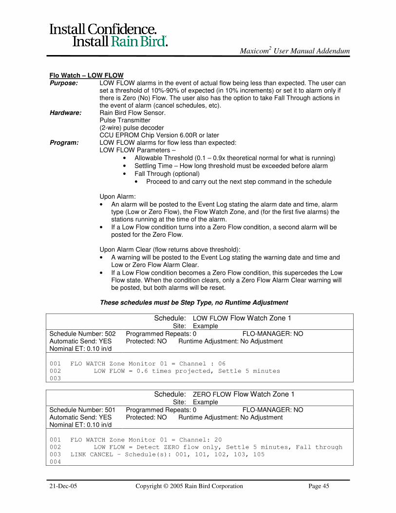
Maxicom2 User Manual Addendum
21-Dec-05 Copyright © 2005 Rain Bird Corporation Page 45
Flo Watch – LOW FLOWPurpose: LOW FLOW alarms in the event of actual flow being less than expected. The user can
set a threshold of 10%-90% of expected (in 10% increments) or set it to alarm only ifthere is Zero (No) Flow. The user also has the option to take Fall Through actions inthe event of alarm (cancel schedules, etc).
Hardware: Rain Bird Flow Sensor.Pulse Transmitter(2-wire) pulse decoderCCU EPROM Chip Version 6.00R or later
Program: LOW FLOW alarms for flow less than expected:LOW FLOW Parameters –
• Allowable Threshold (0.1 – 0.9x theoretical normal for what is running)
• Settling Time – How long threshold must be exceeded before alarm
• Fall Through (optional)
• Proceed to and carry out the next step command in the schedule
Upon Alarm:
• An alarm will be posted to the Event Log stating the alarm date and time, alarmtype (Low or Zero Flow), the Flow Watch Zone, and (for the first five alarms) thestations running at the time of the alarm.
• If a Low Flow condition turns into a Zero Flow condition, a second alarm will beposted for the Zero Flow.
Upon Alarm Clear (flow returns above threshold):
• A warning will be posted to the Event Log stating the warning date and time andLow or Zero Flow Alarm Clear.
• If a Low Flow condition becomes a Zero Flow condition, this supercedes the LowFlow state. When the condition clears, only a Zero Flow Alarm Clear warning willbe posted, but both alarms will be reset.
These schedules must be Step Type, no Runtime Adjustment
Schedule: LOW FLOW Flow Watch Zone 1Site: Example
Schedule Number: 502 Programmed Repeats: 0 FLO-MANAGER: NOAutomatic Send: YES Protected: NO Runtime Adjustment: No AdjustmentNominal ET: 0.10 in/d
001 FLO WATCH Zone Monitor 01 = Channel : 06
002 LOW FLOW = 0.6 times projected, Settle 5 minutes
003
Schedule: ZERO FLOW Flow Watch Zone 1Site: Example
Schedule Number: 501 Programmed Repeats: 0 FLO-MANAGER: NOAutomatic Send: YES Protected: NO Runtime Adjustment: No AdjustmentNominal ET: 0.10 in/d
001 FLO WATCH Zone Monitor 01 = Channel: 20
002 LOW FLOW = Detect ZERO flow only, Settle 5 minutes, Fall through
003 LINK CANCEL – Schedule(s): 001, 101, 102, 103, 105
004

Maxicom2 User Manual Addendum
21-Dec-05 Copyright © 2005 Rain Bird Corporation Page 46
Flo Watch – SEEFPurpose: SEEF (Seek & Eliminate Excessive Flow) takes action to find the location of the cause
of excessive flows (Valve stuck open, broken main) and acts to isolate the problem.Hardware: Rain Bird Flow Sensor.
Pulse Transmitter(2-wire) pulse decoder
Program: SEEF FLOW WATCH takes action for excessive flow:SEEF Parameters –
• Allowable Threshold (1.1 – 1.9x theoretical normal for what is running)
• Settling Time – How long threshold must be exceeded before action
• Type of Action
• Search and Eliminate
• Fall Through (Alarm but no action)
• Normally Closed Master Valve vs. Normally Open
SEEF Results –
• Search and Eliminate possible results
• Main Line Break
• False Alarm
• Faulty Station
• Fall Through
• Alarms but no action taken
User should always place a Link Cancel command at the end of a SEEFinstruction, ensuring all channels in the Flow Zone are canceled following a mainline break.
These schedules must be Step Type, no Runtime Adjustment
Schedule: SEEF Flow Watch Zone 1Site: Example
Schedule Number: 902 Programmed Repeats: 0 FLO-MANAGER: NOAutomatic Send: YES Protected: NO Runtime Adjustment: No AdjustmentNominal ET: 0.10 in/d
001 FLO WATCH Zone Monitor 01 = Channel: 04A+04B
002 SEEF = 1.3 times projected, Settle 3 minutes, (1) Eliminate/ (m)
Maintain normally closed
003 LINK CANCEL – Channel(s): 04,05,07-10
004
005

Maxicom2 User Manual Addendum
21-Dec-05 Copyright © 2005 Rain Bird Corporation Page 47
SEEF – Normally Open Master ValvePurpose: Perform SEEF if using a Normally Open Master Valve (power to close)
Hardware: Rain Bird Flow Sensor.Pulse Transmitter(2-wire) pulse decoderNormally Open Master Valve
Program: The master valve is “parked” on a Satellite station. Station must be “on” for valve to beclosed.
Allow enough time for user to return and see alarm/ condition.
Schedule: SEEF Norm. Open MVSite: Example
Schedule Number: 905 Programmed Repeats: 0 FLO-MANAGER: NOAutomatic Send: YES Protected: YES Runtime Adjustment: No AdjustmentNominal ET: 0.10 in/d
001 FLO WATCH Zone Monitor 01 = Channel: 04A+04B
002 SEEF = 1.2 times projected, Settle 3 minutes, (1) Eliminate
003 M4se Satellite CHANNEL – 02
004 Station 24, 12 hours
005

Maxicom2 User Manual Addendum
21-Dec-05 Copyright © 2005 Rain Bird Corporation Page 48
MAXICOM2 INDICATIONS AND OPERATIONS
Irrigation Properties in Maxicom2
Maxicom2 has a number of settings on both the site-specific and station-specific levels that allow you to set up your
system to compensate for the irrigation requirements and restrictions of varying soil and plant types. Descriptions
of these different settings are detailed below along with guidelines to help the Water Manager determine the proper
settings for his or her system.
Level Site-Specific Station-Specific
Location Site Properties Setup > Irrigation Tab CCU Properties > Station Properties
Settings Crop Coefficient (0.00 – 9.99)
Soil Moisture Holding Capacity (inches)
Soil Infiltration Rate (inches/hr)
Landscape Coefficient (0-999%)
Cycle Time (minutes)
Soak Time (mintues)
Crop CoefficientThe crop coefficient is the evapotranspiration (ET) adjustment factor for the type of plant at the site. Thisadjustment factor is necessary because certain types of plants require more water than other types. Thedefault crop coefficient is 100% and is usually left at this value (due to diverse plant types across onesite). Station-specific adjustments are more common (see “Species Factor” for Landscape Coefficient).
Soil Moisture Holding CapacityHow to determine SMHC using the chart:1. Select the type of soil you are analyzing2. Determine the depth of the root zone (in inches) for the plant material grown in this soil type. Turf
normally requires a root zone of 6 inches.3. Multiply the root zone depth by the soil moisture holding capacity of the soil type selected in #1.4. The result is the total soil moisture holding capacity for this soil profile. This can be entered in the
Site Properties Irrigation Tab.
Basic Soil Moisture Table:Soil Class Soil Moisture Holding Capacity
(inches of water per inch of soil)
Very course(gravely and course sand)
0.048
Course(sand, fine sand, loamy course sand)
0.073
Moderately course(loamy fine sand, sandy loam, fine sandy loam)
0.104
Medium and fine(very fine sandy loam, silt loam, sandy clay)
0.146
Moderately fine(sandy clay loam, clay loam, silty clay loam)
0.175

Maxicom2 User Manual Addendum
21-Dec-05 Copyright © 2005 Rain Bird Corporation Page 49
Advanced Soil Moisture Table
RootZoneDepth
FieldMoistureCapacity
Moisture Heldat Wilting Point
MoistureAvailablefor Plant
Use
Net Inches to Apply perIrrigation for Various %
Soil Type
Feet Inches % Inches Inches 67% 50% 33%
Light Sandy 1.0 1.25 20 0.25 1.00 0.33 0.50 0.67
1.5 1.88 0.38 1.50 0.50 0.75 1.00
2.0 2.50 0.50 2.00 0.66 1.00 1.33
Heavy 1.0 2.25 25 0.56 1.69 0.57 0.85 1.13
1.5 3.38 0.85 2.53 0.84 1.26 1.70
2.0 4.50 1.12 3.38 1.11 1.69 2.26
Medium 1.0 3.67 35 1.28 2.39 0.79 1.20 1.59
1.5 5.50 1.92 3.58 1.18 1.79 2.38
2.0 7.34 2.56 4.78 1.58 2.39 3.25
Soil Infiltration RateSoil infiltration rate (SIR) is how fast water moves into a soil. Infiltration rates are expressed in inches ormillimeters of water per hour. Infiltration rates play an important role in the management of landscapesoils because they influence how rapidly water can be applied without having runoff. Compacted soils,thick thatch, and slopes all work to create low infiltration rates. Soil infiltration rates vary with soil texture.They also decline with time during an irrigation application.
There are many conditions that affect soil infiltration rates such as soil surface conditions, soil texture,structure, slope, and soil water content. Thatch layers in turfgrass can cause slowing of infiltration ratesand should be watched.Sandy soils will generally take in water very quickly, usually more than 1.0 inch (2.5 cm) per hour. Claysoils take in water very slowly, generally less than 0.1 inches (0.02 cm) per hour.Slopes will take in water at a slower rate than flat areas. Utilizing Rain Bird’s Cycle + Soak™ makesscheduling these low infiltration rate areas much easier.
Maxicom² uses soil infiltration rates to determine how much rainfall was actually absorbed by the soil.This information is very useful for determining the water content of the irrigated soil profile.
The following chart shows representative infiltration rates for different soil textures.Soil Texture Inches/hr cm/hr
Sand - course 1.00 - 8.00 2.50 - 20.00
Sand - very fine 0.50 - 3.10 1.25 - 8.00
Sandy loam 0.40 - 2.60 1.00 - 6.50
Loam 0.08 - 1.00 0.20 - 2.50
Clay loam 0.04 - 0.60 0.10 - 1.50
Clay 0.01 - 0.10 0.02 - 0.25* These values are approximate. Infiltration rates can vary widely, depending on surface conditions andsoil water content.
Landscape CoefficientIn determining the irrigation runtimes for landscaped areas, many factors need to be considered in orderto account for differences in environment, planting density, etc. The combination of these factors givesus the landscape coefficient. When the landscape coefficient is used in combination with a referenceET, a specific localized ET can be calculated for very small microclimate areas.The ET for a landscape varies as a function of the mix of plant species, the density of planting and theeffects of a microclimate. By evaluating each factor and assigning it a numeric value, an estimate of the
Maxicom2 User Manual Addendum
21-Dec-05 Copyright © 2005 Rain Bird Corporation Page 50
overall landscape coefficient can be made. The following equation can be used to calculate thelandscape coefficient:
Kl = Ks X Kd X KmcWhere:Kl = Landscape coefficientKs = Species factor (Crop Coefficient)Kd = Density factorKmc = Microclimate factor
Species Factor (Ks)
The evapotranspiration rate of different plants vary considerably. Some transpire large amounts of waterwhile others transpire very little. A factor can be related to various plant species to estimate waterrequirements of each plant type. The Species factor is also known as the crop coefficient. This factorcan many times be obtained through local sources such as Agriculture Extension services.
Density Factor (Kd)
Landscapes can vary greatly in plant density, especially with shrub and groundcover plantings. Newlyplanted or sparsely planted areas often have less leaf surface area than mature, dense landscapeplantings. Even though individual plants in a sparsely planted area may lose more water for a given leafarea, the total water loss from a dense planting will be higher due to the greater total leaf surface areafor the site. A density factor (Kd) of some sort is needed to account for these differences in water loss.
Microclimate Factor (Kmc)
Environmental conditions may also vary significantly within a single landscaped site. Structures andpaved areas typical of urban areas greatly affect these conditions. The microclimate factor (Kmc) isrelatively easy to establish. An average microclimate condition is one in which buildings, pavements,slopes, shade and reflection do not influence the site, and therefore Kmc = 1.0 (or 100% if based on apercentage system)A high microclimate condition is one in which the landscape is surrounded by highheat absorbing surfaces, heat reflecting surfaces and/or high wind conditions, so Kmc might equal 1.4for a certain situation. A low microclimate is one in which the plantings are shaded or protected from thewind, so Kmc might equal 0.5.
Cycle + SoakTM
The Rain Bird Cycle + SoakTM
water management feature matches sprinkler/drip application rates tosoil/slope infiltration rates. Puddling and run off can occur when water is applied faster than thesoil/slope can except it. Irrigation applied to sandy soils can run past the plant root zone if applied toofast or in a single application.
Once programmed, Cycle + SoakTM
automatically divides each stations total run time into a maximumcycle time the soil/plant can accept. If more than one cycle is required, a minimum soak-in time isinserted between cycles. While a station is soaking, another station is cycled, preventing controller downtime. Cycle + Soak
TM spoon feeds the soil until the total run time has been fulfilled by all stations.
When the irrigation requirement changes, the system operator can use the water budget feature toadjust the percent of change desired for each program. Cycle + Soak
TM does the rest of the work for
you!
The attached chart shows examples of how to utilize Cycle + SoakTM
for various soil/slope conditionswith various sprinkler precipitation rates. The chart assumes a pre-wetted soil condition.

Maxicom2 User Manual Addendum
21-Dec-05 Copyright © 2005 Rain Bird Corporation Page 51
Suggested Cycle + SoakTM
Times
Precip. Rate
In. Per Hour
0.1” - 0.5”
Micro/Rotors
0.5” - 1.0”
Rotors
1.0” -1.5”
Rotors/Sprays
1.5” - 2.0”
Sprays
2.0” - 2.5”
Sprays
Sandy Soil
0-5% Slope
60 min. Cycle
0 min. Soak
60 min. Cycle
0 min. Soak
60 min. Cycle
0 min. Soak
60 min. Cycle
0 min. Soak
45 min. Cycle
15 min. Soak
Sandy Soil
5-8% Slope
60 min. Cycle
0 min. Soak
60 min. Cycle
0 min. Soak
60 min. Cycle
0 min. Soak
45 min. Cycle
15 min. Soak
30 min. Cycle
30 min. Soak
Sandy Soil
8-12% Slope
60 min. Cycle
0 min. Soak
60 min. Cycle
0 min. Soak
45 min. Cycle
15 min. Soak
30 min. Cycle
30 min. Soak
12 min. Cycle
48 min. Soak
Sandy Soil
12%+ Slope
60 min. Cycle
0 min. Soak
30 min. Cycle
30 min. Soak
20 min. Cycle
40 min. Soak
15 min. Cycle
45 min. Soak
12 min. Cycle
48 min. Soak
Loam Soil
0-5% Slope
60 min. Cycle
0 min. Soak
45 min. Cycle
15 min. Soak
30 min. Cycle
30 min. Soak
24 min. Cycle
36 min. Soak
20 min. Cycle
40 min. Soak
Loam Soil
5-8% Slope
60 min. Cycle
0 min. Soak
30 min. Cycle
30 min. Soak
20 min. Cycle
40 min. Soak
15 min. Cycle
45 min. Soak
12 min. Cycle
48 min. Soak
Loam Soil
8-12% Slope
50 min. Cycle
10 min. Soak
24 min. Cycle
36 min. Soak
16 min. Cycle
44 min. Soak
12 min. Cycle
48 min. Soak
10 min. Cycle
50 min. Soak
Loam Soil
12%+ Slope
36 min Cycle
24 min. Soak
18 min. Cycle
42 min. Soak
12 min. Cycle
48 min. Soak
8 min. Cycle
52 min. Soak
6 min. Cycle
54 min. Soak
Silt Soil
0-5% Slope
36 min. Cycle
24 min. Soak
18 min. Cycle
42 min. Soak
12 min. Cycle
48 min. Soak
8 min. Cycle
52 min. Soak
6 min. Cycle
54 min. Soak
Silt Soil
5-8% Slope
30 min. Cycle
30 min. Soak
15 min. Cycle
45 min. Soak
10 min. Cycle
50 min. Soak
8 min. Cycle
52 min. Soak
6 min. Cycle
54 min. Soak
Silt Soil
8-12% Slope
18 min. Cycle
42 min. Soak
9 min. Cycle
51 min. Soak
6 min. Cycle
54 min. Soak
5 min. Cycle
55 min. Soak
4 min. Cycle
56 min. Soak
Silt Soil
12%+ Slope
12 min. Cycle
48 min. Soak
6 min. Cycle
54 min. Soak
4 min. Cycle
56 min. Soak
3 min. Cycle
57 min. Soak
2 min. Cycle
58 min. Soak
Clay Soil
0-5% Slope
18 min. Cycle
42 min. Soak
9 min. Cycle
54 min. Soak
6 min. Cycle
54 min. Soak
5 min. Cycle
55 min. Soak
4 min. Cycle
56 min. Soak
Clay Soil
5-8% Slope
12 min. Cycle
48 min. Soak
6 min. Cycle
54 min. Soak
4 min. Cycle
56 min. Soak
3 min. Cycle
57 min. Soak
2 min. Cycle
58 min. Soak
Clay Soil
8-12% Slope
10 min. Cycle
50 min. Soak
5 min. Cycle
55 min. Soak
3 min. Cycle
57 min. Soak
2 min. Cycle
58 min. Soak
1 min. Cycle
59 min. Soak
Clay Soil
12%+ Slope
7 min. Cycle
53 min. Soak
4 min. Cycle
56 min. Soak
3 min. Cycle
58 min. Soak
2 min. Cycle
58 min. Soak
1 min. Cycle
59 min. Soak
Maxicom2 User Manual Addendum
21-Dec-05 Copyright © 2005 Rain Bird Corporation Page 52
Maxicom2 Icon – Right Click Options
The Maxicom2 icon (bird) that appears in the system tray allows a number of options when a user right
clicks on it. These options differ depending on whether the user interface is open or closed:
� If the user interface is open, when you right click on the "Bird in the tray," the two options available toyou are "Bring Maxicom
2 to Front," and "Disable Auto Contacting."
� If the User interface is closed when you right click on the "Bird in the tray," the three optionsavailable to you are "Launch Maxicom
2," "Disable Auto Contacting," and "Exit Maxicom
2 Control
Engine."
It is important to realize these different options exist, otherwise a user may accidentally disable autocontacting instead of exiting the control engine (prior to rebooting the computer, etc).
Maxicom2 Warning System
Maxicom2 is designed with a warning system to help prevent users from accidentally performing action
like deleting sites, etc. This warning system appears as a dialog box that will ask the user a question like:“Are you sure you want to delete this site?” This warning system is most frequently seen with the “Areyou sure you want to exit Maxicom
2?” dialog box when a user goes to shut down the user interface.
This warning system can be turned on and off. If the user goes to System > Properties > Preference tab,he/she will see a check box for “Enable Maxicom
2 Warning System.” If this box is not checked, the
warning dialog boxes will not appear. It is recommended that users leave these warnings enabled toprevent accidentally deleting sites, etc.
Rain Shut Down
The Maxicom2 Rain Shut Down feature was designed to allow a user-initiated shutdown of a site’s non-
protected irrigation. While originally designed (and named) for rain events, this feature is often used asan emergency shutdown for a site. As such, it is necessary to ensure proper understanding of thefunctionality of a Rain Shut Down:
The Maxicom2 Rain Shut Down feature allows a user to turn off all currently scheduled, non-protected
irrigation for a site. When a Rain Shut Down is initiated, the Central Controller does a one-time canceland delete of all non-protected schedules in the CCU and then prevents all automatic send contacts ofthe site until the Rain Shut Down is cancelled. That a site is in the state of "Rain Shut Down" does notmean that irrigation will not occur, since protected schedules will still run (used by some locations forlighting, etc). Also, even though a site is in Rain Shut Down, a CCU can be sent schedules throughmanual contact (only automatic contacts are prevented). And, those irrigation schedules will run.
The ability to send schedules by manual contact and have them run while the site is in Rain Shut Downis intended to provide users a means to accomplish any irrigation tasks not covered by their normallyprotected schedules (including, but not limited to, system test schedules, troubleshooting, etc).
Once the Rain Shut Down is cancelled, ET Stacking for the next scheduled irrigation day will be basedon the irrigation day pattern of the schedule. No additional irrigation will occur to make up for scheduleddays missed while in Rain Shut Down.
Maxicom2 User Manual Addendum
21-Dec-05 Copyright © 2005 Rain Bird Corporation Page 53
Runtime Roster Number Colors
Red or black numbers or dashes are shown in Runtime Roster so that the user knows if there is adiscrepancy between the actual and projected runtimes. Following are reasons why you would eithersee Red or Black numbers or dashes:
Black number: This denotes that the station associated with the black number was supposed to run anddid. It also shows that the actual and projected durations match each other within this time range. Youmay see black numbers that do not match each other depending on the Runtime Roster VarianceThreshold setting (located in System Properties on the Preference tab).
Black zero in the Projected view: This station was not projected to run and did not actually run in thistime range.
Black dash in the Actual view: This station was not supposed to run and did not actually run in this timerange.
Red number: You will see this in both the Actual and Projected views whenever the station runtime doesnot match within the selected time range. Reasons may include, but are not limited to:
• A station is run manually from the Central Control (OMSC or FREEDOM)
• Satellite failure
• CCU-to-satellite communication problems
• Communication between the CCU and Central Control is interrupted and an automatic Send contactis missed.
Red zero in the Projected view: Nothing was projected to run, but this station did run. This will,oftentimes, occur when a station is run manually from the Central Control (OMSC or FREEDOM).
Red dash in the Actual view: This station was projected to run but did not actually run. Examplesituations when this may occur include when a schedule is not successfully sent to the CCU, or irrigationis cancelled by a real-time sensor event (CANCEL IF, LINK CANCEL, or SEEF) such as rain, or aschedule is manually cancelled (by OMSC or FREEDOM).
Explanation of ET Status
To reduce confusion in ET Checkbook, a new ET status of “Updated” was added in Version 2.0. Thesymbolic display is an exclamation mark (!). If a Weather Source is contacted after a failed attempt andirrigation has already occurred, then 1) the ET values will be updated, and 2) an exclamation mark andthe word “Updated” will be displayed next to the values in the ET Checkbook.
The most common reason for seeing this status is when a Weather Source contact fails. If there is noWeather Source contact by the time that the Site “auto send” contact occurs, then the Reference ETfrom the previous day is used in determining the Irrigation ET. If it has been 2 or more days withoutWeather Source contact, Maxicom2 will then use the default ET. The next time that the Weather Sourceis successfully contacted, MC2 gets the actual ET data that it previously missed and updates previousday(s) Reference ET and Rain. This places a discontinuity in the Balance column since the Irrigation ETdoes NOT change after it has been sent to the CCU. The “Updated” status is to alert the user of thereason for this apparent discontinuity.

Maxicom2 User Manual Addendum
21-Dec-05 Copyright © 2005 Rain Bird Corporation Page 54
Maximum Daily ET Value
There has been confusion among some customers recently regarding the effect that Maximum Daily ETValue has on irrigation. The Maximum Daily ET Value is set for a site in the “Irrigation” tab of “SiteProperties.” This value (in inches per day, etc) is the maximum amount the system will irrigate on oneday (for ET-based schedules) to replace water lost by evapo-transpiration.
For example, say the Maximum Daily ET Value is set at 0.50 inches/day, and your schedule waters lessfrequently than every day – if the Irrigation ET stacks greater than 0.50 inches between irrigation days,the system will still only irrigate a max of 0.50 inches on its scheduled day.
ET Stacking
In Maxicom2, ET-based scheduling allows the ET for “non-water” days to be “stacked” (accumulated in
order to be replenished on irrigation days). Some sites will desire to not have the ET stacked from non-water days, or to stack a different period or frequency than what is represented by the irrigationschedule. This can be addressed in a Master/Slave schedule format, using different combinations ofSTART DAY instructions in the Master and the Slave schedules. However, there are a couple guidelinesto be considered in this process:
1) The Slave schedule should contain a Start Days instruction without a Start Time instruction.2) ET will be accumulated no farther back than the last Master start day or the last Slave start day,
whichever is closer to the current irrigation day.3) If the Slave schedule has START ON - all 7 days, irrigation will occur on the start days in the Master
schedule without any ET accumulation for the non-water days.4) Important: If the Slave Schedule has the Master start day, as well as the day after the Master start
day THEN only one day of ET is applied on that Master start day (ET is not "stacked" oraccumulated since the previous start day).
5) If the user writes an ET-based Schedule and omits desired non-water days using the EventCalendar, Maxicom
2 will not accumulate ET or Rainfall for that schedule during the omit days. Note:
This feature may not be available in the future due to changes required in the Event Calendar toenable Odd/Even scheduling (planned post-2.1).
NOTE: These guidelines and the following examples are based on a single Master schedule per Slavedesign. Scheduling methods that include two or more Master schedules that link start the same Slaveschedule, or nested Slave designs, do not react the same.
Examples:SCHEDULE START DAYS
Master MON TUE WED THU FRI SAT SUN
Slave
Result: Irrigation on each day only includes that day’s ETNote: Because the Slave has no start days, ET accumulation is based on the Masterschedule.
SCHEDULE START DAYS
Master MON WED FRI
Slave MON TUE WED THU FRI SAT SUN
Result: Irrigation on each Master start day only includes that day’s ET
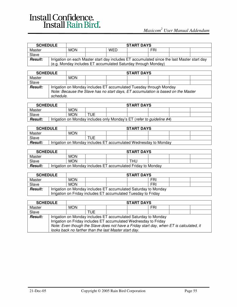
Maxicom2 User Manual Addendum
21-Dec-05 Copyright © 2005 Rain Bird Corporation Page 55
SCHEDULE START DAYS
Master MON WED FRI
Slave
Result: Irrigation on each Master start day includes ET accumulated since the last Master start day(e.g. Monday includes ET accumulated Saturday through Monday)
SCHEDULE START DAYS
Master MON
Slave
Result: Irrigation on Monday includes ET accumulated Tuesday through MondayNote: Because the Slave has no start days, ET accumulation is based on the Masterschedule.
SCHEDULE START DAYS
Master MON
Slave MON TUE
Result: Irrigation on Monday includes only Monday’s ET (refer to guideline #4)
SCHEDULE START DAYS
Master MON
Slave TUE
Result: Irrigation on Monday includes ET accumulated Wednesday to Monday
SCHEDULE START DAYS
Master MON
Slave MON THU
Result: Irrigation on Monday includes ET accumulated Friday to Monday
SCHEDULE START DAYS
Master MON FRI
Slave MON FRI
Result: Irrigation on Monday includes ET accumulated Saturday to MondayIrrigation on Friday includes ET accumulated Tuesday to Friday
SCHEDULE START DAYS
Master MON FRI
Slave TUE
Result: Irrigation on Monday includes ET accumulated Saturday to MondayIrrigation on Friday includes ET accumulated Wednesday to FridayNote: Even though the Slave does not have a Friday start day, when ET is calculated, itlooks back no farther than the last Master start day.
Maxicom2 User Manual Addendum
21-Dec-05 Copyright © 2005 Rain Bird Corporation Page 56
Relationship between Minimum, Maximum, and Irrigation ET
There have been some reports of confusion, regarding ET accumulation and Irrigation ET, in that itsometimes seems like Maxicom
2 is a couple days behind in what it is using for Irrigation ET. An
explanation of this process follows:
The ET Checkbook operates by first subtracting the current Reference ET (calculated from the WeatherStation data) from the previous day’s balance. It then adds in any Accepted Rainfall. It then comparesthis new balance to the product of Soil Moisture Refill Percentage times the Soil Moisture HoldingCapacity (SMRP X SMHC).
Irrigation ET is the amount (in inches) that ET-based schedules are set to irrigate for, in order to refill thesoil profile to the Soil Moisture Refill % amount. Maxicom
2 always uses Irrigation ET, not Reference ET,
to determine what ET to be used to adjust schedule runtimes.
When Irrigation ET is calculated, there are two user-set limits on it:
1) Maximum ET corresponds to the maximum amount of ET (in inches) that irrigation will “make up for”in one day. If the difference between the checkbook balance and the product of SMRP X SMHC exceedsthe value for Maximum ET, Maxicom
2 will set the Irrigation ET to the value of Maximum ET.
2) Minimum ET corresponds to the minimum amount of ET (in inches) that irrigation will “make up for.” Ifthe difference between the checkbook balance and the product of SMRP X SMHC, is less than the valueset for Minimum ET, irrigation will not occur. So, in the ET checkbook, Irrigation ET will show 0, until thedifference exceeds Minimum ET.
Schedules Running Every DaySo, for schedules that run every day of the week, Maxicom
2 will, on a daily basis, take the previous day’s
balance, subtract the Reference ET, add back accepted rainfall, and compare this balance to the limit ofthe Soil Moisture Refill Percentage (SMRP) times the Soil Moisture Holding Capacity (SMHC):
• If the balance is at or above the product of SMRP X SMHC, irrigation will not occur.
• If the balance is below the product of SMRP X SMHC but the difference is less than Minimum ET,irrigation will not occur.
• If the balance is below the product of SMRP X SMHC and the difference is greater than or equal toMinimum ET but less than Maximum ET, irrigation will occur. And, Irrigation ET will be set at thisdifference.
• If the balance is below the product of SMRP X SMHC and the difference is more than Maximum ET,irrigation will occur. And, Irrigation ET will be set at the value of Maximum ET.
Schedules with Start Day Patterns Other than Every DayThe confusion occurs with schedules that do not run every day, because Maxicom
2 does something that
is not immediately intuitive:
• As soon as the value of the difference between the ET balance and the product of SMRP X SMHCexceeds the Minimum ET, Irrigation ET is set at this value to be used during the next scheduledirrigation.
• Maxicom2 then starts a “behind-the-scenes” counter adding up ET that accumulates beyond this first
amount.
• If the behind-the-scenes counter exceeds Minimum ET before the next scheduled irrigation occurs,this value is added to the Irrigation ET. So, anytime before the next scheduled irrigation, that thisbehind-the-scenes counter exceeds the Minimum ET threshold, the amount on the counter is addedto the Irrigation ET value and the counter restarts.

Maxicom2 User Manual Addendum
21-Dec-05 Copyright © 2005 Rain Bird Corporation Page 57
• When the scheduled irrigation day comes, Maxicom2 uses the value that is shown as the Irrigation
ET. Any balance in the behind-the-scenes counter, is not used on that scheduled day. Instead, thisamount becomes the start to the tally for the following scheduled irrigation day. This is why somecustomers perceive Maxicom
2 to be “a couple days behind” in ET.
• If, at any time, the sum being used for Irrigation ET exceeds Maximum ET, then the value forMaximum ET is used the next scheduled irrigation day. The amount that the sum exceededMaximum ET is then carried over to the next scheduled irrigation day. However, if the user hasinfrequent start days, during hot months, this may cause Maxicom
2 to “fall behind” on ET.
The adverse effects of the “behind-the-scenes” counter needing to reach Minimum ET prior to adding tothe value used for Irrigation ET, and the effects of that Irrigation ET sum exceeding Maximum ET, aremost readily apparent in Sites with the following:
• A medium to high Reference ET
• A high Minimum ET
• A small difference between Minimum and Maximum ET
• An infrequent start day pattern (e.g. a Monday, Thursday schedule)
Recommendations to help minimize these effects include reducing Minimum ET, adding more start days,and investigate increasing Maximum ET.
Weather Station Contacts and ET Data
Typically, Maxicom2 users will set their weather station contact for as soon before their auto-send
contacts as they can. But, we have recently seen confusion regarding how “current” the data thatMaxicom
2 uses, is.
For Maxicom2 Versions 1.10 – 2.1: When the ET data is received from the Weather Station, Maxicom
2
will look at the last “full” hour of data, and then use the data up until one hour before that in order tocalculate the irrigation ET. For example, if the weather station contact was at 3:30 PM, the last full hourof data ended at 3 PM, so Maxicom
2 will use the data up until 2 PM for that night’s ET calculation.
Because of this, if it rains at 2:30 PM, that rainfall will not be considered until the following night.
For Maxicom2 Version 3.0: When the ET data is received from the Weather Station, Maxicom
2 will look
at the last “full” hour of data and use that data. For example, if the weather station contact was at 3:30PM, the last full hour of data ended at 3 PM, so Maxicom
2 will use the data up until 3 PM for that night’s
ET calculation. Note: If the weather station contact is soon after the top of the hour, it is possible that theWeather Station may not have tabulated all data for that previous hour, yet. In that case, Maxicom
2 will
use up to the prior hour’s data. It is possible, however, that on the following day, all the data is tabulatedby the contact time and Maxicom
2 will pull 25 hours of data. This could cause Maxicom2 to “readjust” the
previous day’s ET Checkbook number. While the ET will be compensated for, it may appear thatMaxicom
2 did not irrigate what it was supposed to on the adjusted day. For this reason, it is
recommended that weather station contacts do not occur right after the top of the hour.
Site Rain Can Accounting in Irrigation ET
Accumulated rainfall from a Site Rain Can (SRC – RainGauge) used as a Site Weather Source (notsolely for Rain Watch) does go into the Irrigation ET calculation, but it is accounted for as part of the dayfollowing the day it is received. The CCU does not do ET calculations. So, any rainfall received at a SRChas to wait until the next Auto-Receive contact time before it makes it into the Maxicom
2 database and is
accounted for in Irrigation ET calculations.

Maxicom2 User Manual Addendum
21-Dec-05 Copyright © 2005 Rain Bird Corporation Page 58
Example Timeline:
Time Event
6:00 AM – Day 1 Auto-Receive previous night’s irrigation data
12:30 PM – Day 1 Rain Amount X received at SRC and logged in CCU
6:00 PM – Day 1 Auto-Send contact with new runtimes
6:00 AM – Day 2 Auto-Receive previous night’s irrigation data including Rain Amount X loggedon Day 1.
6:00 PM – Day 2 Auto-send contact with new runtimes that include adjustment for Rain Amount X
Effect of Rain on Irrigation ET (schedules that do not run every day)
In relation to Min, Max, and Irrigation ET - Accepted Rainfall is added into the ET Checkbook as part ofthe process to adjust the daily balances and determine Irrigation ET. However, for schedules that do notrun every day, there is an algorithm that Maxicom
2 uses as part of the process to count rainfall for
adjusting the associated runtimes:
If a site receives rain that is larger than the Reference ET for that 24-hour period, then Maxicom2
will cancel all previously accumulated irrigation ET for that schedule. This, in effect, zeroes outthe Irrigation ET counter (erasing irrigation ET not yet applied, and any on the “behind-the-scenes” counter).
This portion of the algorithm was a change that occurred in 1999. Theoretically, it may not seem right,but it was designed to prevent irrigation on a day where ample rainfall has occurred, such that the soilmay be temporarily saturated and water would be wasted. Also, it addresses the situations wherecarrying over the irrigation ET on schedules with infrequent start days has the potential to create a“never-catch-up” scenario.
NOTE: As stated above - this case only relates to schedules that do not run every day.
Running Stations for Seconds
Typically, when setting up non-ET-adjusted schedules, users will set runtimes in minutes. However, forsome applications (nurseries, wetting down sports fields) it is desired to run station in increments ofseconds. It is possible to program station runtimes in seconds. However, the user may run intolimitations because of the opening/closing time of valves (so, extremely short runtimes are notrecommended and all schedules should be adequately tested on the system).
IMPORTANT:1) This will need to be a step schedule (not flo-managed)2) The Runtime Roster WILL have red numbers since logging is only in minutes.
Since these schedules are typically be used to “wet something down” rather than as part of the typicalirrigation by ET, it is believed those caveats are acceptable.
How to write the schedule: Write a normal, non-adjusted step schedule. When you set station times(using the wizard) consider hours as minutes and minutes as seconds. Once you are back to the editor,change the word “minutes” in the schedule to “seconds”. For example, to run a station for 1 Minute 15Seconds, the schedule looks like:

Maxicom2 User Manual Addendum
21-Dec-05 Copyright © 2005 Rain Bird Corporation Page 59
001. START ON – MONDAY TUESDAY WEDNESDAY THURSDAY FRIDAY SATURDAY
SUNDAY
002. START AT – 03:15PM
003. M4se Satellite CHANNEL – 01
004. Station 01, 075 seconds
This WILL pass the schedule auditor.
NOTE: If this is to be used on a sports field (artificial grass), it would probably be with rotors. The “time”needs to be long enough for the rotors to make at least one cycle in that case (and take into accountvalve opening time).
Using a Pager with Maxicom2
It is possible to receive notification by pager in the event of certain alarms. This functionality has beenaccomplished in some locations through the use of a Radio Shack auto-dialer and schedules inMaxicom
2. Schedules used can range from a step at the end of a SEEF schedule to steps following a
rain event, wind event, etc. The auto-dialer is triggered by simply turning on a dry contact relay (24VAC) off a spare station.
Needs:1) Auto-dialer (Radio Shack Catalog #980-0582)2) Dry Contact Relay - Typical 24VAC dry contact relay...manufacturers vary. Most Maxicom
distributors should know where to find this.3) Spare station4) Phone line to the auto-dialer (can be split off the CCU line).
This is a Site feature not a Central feature. The auto-dialer is used to make outbound alarm phone callsfrom the CCU's phone line. These auto-dialers are commonly used in the residential & commercial alarmsystem business. This unit can send a number (alarm message based on the site number) or userrecorded voice message. You can program the unit to make a single or multiple calls. Use a spareSatellite Controller Station to start the auto-dialer using the 24VAC output and a dry-contact relay. Addthe Channel & Station number of the auto-dialer output after the SEEF line in the Flo-Watch Schedule.The auto-dialer will then only call out if a mainline break has been detected.
Associated detail drawing is Maxicom2 Detail Drawing # 410.

Maxicom2 User Manual Addendum
21-Dec-05 Copyright © 2005 Rain Bird Corporation Page 60
Activating Door Locks with Maxicom2
Over the years, we have had several customers controlling restroom door locks with Maxicom. Whilemost of you may not have this need, some of you may run into customers who desire it. Here are someof the lessons learned from other users:
1. Control the door locks with a controller station(s) not output decoders (used previously in centralcontrol systems). Output decoders have DC output and often require a relay interface to controlthe door locks.
2. Utilize 24VAC latching solenoid door locks that do not require continuous power to control thestate (open or closed). These are available in single pole (requiring one controller station tooperate) or double pole (requiring two controller stations to operate). This is a big plus whenusing multi-station operation & Flo-Manager for irrigation on the same controller that controls thedoor locks. We have found several lock manufacturers that have this feature.
3. Be sure to install a lock that has an internal manual override incase someone is in the restroomwhen the door is locked.
4. The Maxicom2 schedule to operate the locks with a latching solenoid is fairly straightforward:
Write a schedule for the controller station that operates the door lock for 1 minute to lock thedoor at the desired day & time. Include a pause for "X" hours (the desired time to keep the doorlocked). Then turn on the same station for 1 more minute to open the door lock.
5. For monitoring door “state”: We do not know of a latching door lock with a built in sensor foropen/close verification. There might be one on the market but we have not seen. If you can't findone, we would look to the alarm industry for a magnetic door sensor that will confirm the door isin the closed position. The door alarm circuit would need to interface with a sensor decoder orsatellite sensor input to tell Maxicom
2 if the door was open or closed. Depending on the sensor,
this may require a relay to interface the door sensor to Maxicom2.
6. A separate schedule can be written to monitor the door position with the door sensor. If the doorshould be locked but the door is open you can interface an onsite alarm light or activate an autodialer to place a call through a phone line (can share the CCU phone line). This alarm phone callcan be to a phone number (voice message) or pager/cell phone number (numeric page). Thisauto dialer requires another controller station for activation. We typically use alarm system autodialers that can be purchased at Radio Shack or another alarm equipment dealer.

Maxicom2 User Manual Addendum
21-Dec-05 Copyright © 2005 Rain Bird Corporation Page 61
CCU OPERATIONS
Sending Configuration changes to the CCU
The configuration is automatically sent to the CCU during an automatic send contact and also wheneverat least one schedule is sent manually.
The “Send Configuration” function was added in Maxicom2 to allow it to be sent to the CCU afterconfiguration (CCU Properties) changes are made without having to send a schedule or wait until theauto send time in order to update the CCU.
The configuration does not need to be manually sent, only after CCU Properties are changed and it isadvantageous to send the changes before the next scheduled auto send contact. For example: If a newflow sensor or satellite has been configured and the configuration is not sent to the CCU, then therewon't be any log for that device until the configuration gets sent to the CCU. Or, for instance, the settingfor a flow sensor is changed from 10 gallons per pulse to 20 gallons per pulse, then the new value won'tbe logged by the CCU until the configuration is sent.
CCU Polling of Radio Link Satellites
The CCU polls Radio Link Satellite channels as follows:
• Immediately following a station output command (any change to station output, including cancel),each affected channel is polled.
• Every channel that is configured with sensor input(s) is polled at least once every two minutes.
• Every channel with active sensor input is polled every minute. Active sensor input is one thatregistered at least one pulse during the previous poll.
• All other satellite channels are polled at a rate of up to four channels every minute.
At the minimum polling rate of four channels per minute, the greatest possible interval between polls forany individual satellite channel is 7 minutes. This could occur only if more than 24 channels areconfigured, there are no station output commands for the channel, and the channel is not configured forsensor input.

Maxicom2 User Manual Addendum
21-Dec-05 Copyright © 2005 Rain Bird Corporation Page 62
Wireless Diagnostics
For Link Radio Sites (CCUs) if you go to “Site” on the upper menu bar, you will see an option for“Wireless Diagnostics.” This option opens a dialog window that displays the Wireless Diagnosticsinformation for the current site only. This item will not be available if a two-wire CCU or Site-Sat hasbeen selected. The dialog window displays information in the following format:
CCU Channel 1 Channel 2
DEVICE CCU-28 Radio Link 01:M4se
Log 1(Null):0 Busy:0 Free:0 Link:0
MA:N/AMR:N/A
Log 2(Null):0 Busy:0 Free:0 Link:0
MA:N/AMR:N/A
On the top row, you have labeled columns for the CCU and then each channel on that CCU (Channel1…. Channel 28). On the second row, the configuration is shown (CCU type and device type on eachchannel). An explanation of the remaining data is as follows:
Column 1 has a header for each row as “Log 1”, “Log 2”… “Log 24”. These headers are a representationof the “data set” and their meaning depends on what column you are in. The CCU column is hourly datafor the day selected, so, “Log 1” is “12:01 AM – 01:00 AM.” The Channel columns are representations ofcontacts where Maxicom
2 receives logs from the CCU (Auto Send or Auto Receive contact, or Manual
contact where user “gets logs”). So, Log 1 is the first contact of that day, etc. This is important, becauseit means the data in the Channel columns has no relation to the data in the CCU column on the samerow.
CCU ColumnThe CCU column has four data measures (Null, Busy, Free, Link). This data is measured in 10ths ofseconds in the hour (1 hour = 60 minutes = 3600 seconds = 36,000 tenths of seconds), so there are36,000 data points. This is because the CCU checks the radio Carrier Detect (CD) signal 10 times everysecond.� The Null value will always be zero.� Busy represents the amount where the CD is active but the CCU is not sending or expecting to
receive an answer from a Satellite. This helps determine if the frequency being used is noisy or usedby another entity.
� Free represents the amount where the CD is inactive (nothing on the frequency).� Link represents the amount where the CCU is sending to satellites or receiving messages back from
satellites.Remember: These are hourly logs from midnight to midnight for the day selected.
Channel ColumnThe Channel column is what often causes the most confusion. Each “Log” represents the time periodbetween contacts where Maxicom
2 gets logs from the CCU (Auto Send/Receive or Manual with “get
logs”). So, Log 1 is for the first contact of that day and displays the data since the previous contact. Log2 is the second contact and displays data since the contact represented in Log 1. If you only have oneAuto Receive and one Auto Send with no manual contacts where you get logs, you will only have data intwo boxes in the column.
Data is represented in two categories, Messages Answered (MA) and Messages Received (MR). Bothare shown as a percentage of the messages sent by the CCU to the device on that channel.� MR are logged by the satellite (so number displayed is the messages the Satellite received from the
CCU as a percentage of the messages the CCU sent in that period). The CCU gets the MR number
Maxicom2 User Manual Addendum
21-Dec-05 Copyright © 2005 Rain Bird Corporation Page 63
from the satellite every hour on the hour. After the CCU gets the data from the satellite, the satelliteclears them from memory.
� MA are logged by the CCU (so number displayed is the messages the CCU receivesacknowledgement for from the Satellite as a percentage of the messages the CCU sent in thatperiod).
After the CCU logs the data into Maxicom2, it clears them from memory and starts logging, again.
Some customers have encountered issues interpreting this because MR and MA do not always matchup due to the logging format. A good example (and one often encountered) is if you have the AutoReceive and the Auto Send in the same hour:� At the top of the hour, the CCU gets the MR number from the Satellite.� Some time later (at T1), the Auto Receive contact is made, and the CCU sends all data to Maxicom
2
(let’s say this data shows up as Log 1) and then clears it’s memory and starts logging, again.� At some time later (T2), in the same hour, the Auto Send contact is made. The CCU once again
sends the wireless data to Maxicom2 and this will show up as Log 2.
ÖÖ
Log 2 represents the time period between T1 and T2. Since we did not hit the top of the hourin this period, the CCU did not get any MR data from the satellite, so MR would be zero.Assuming the CCU did send messages during this time, though, there will be an MA value.Because the MR is zero, the block will be flagged red, even if MA is 100%.
You can also see how, if there is yet another contact in the day, there could be more MessagesReceived than the CCU sent. Those messages received by the satellite between the top of the hour andT2 will not be logged in the CCU until the top of the next hour. However, the number of messages sent inthat time and the MA number was cleared from the CCU at the T2 contact. So, MR may show up as>100%.
The Wireless Diagnostics were meant to be a tool used by Rain Bird technical personnel. While they canbe helpful for catching radio issues, etc, please be aware of potential “false discrepancies” in the data asdescribed above.
Flow Meter Settings (Gallons per Pulse)
When setting gallons per pulse for a flow meter (CCU Properties > Sensor Properties), the Maxicom2
User Interface allows you to input non-integer values (decimal places). However, Maxicom2 will only use
whole numbers when monitoring flow and will round the value to the nearest whole number (any valueless than 1 will be rounded up to 1). For Example, if you enter 1.7 Gallons/Pulse, Maxicom
2 will count
flow as 2 Gallons/Pulse. Likewise, 6.3 would be rounded down to 6.
Flow Logging and Pulse Decoder Limits
For CCU operations, the published limit on flow sensor logging is a max of 7 flow sensors and the limitfor pulse decoders at 10 pulses/min (ppm) is six per CCU (on the Two-Wire path). Both of these limitsare worst-case scenarios and may be adapted depending on a site’s needs:
Flow LoggingThe actual limitation in the CCU is that it can only hold up to 7 full 24-hour @ 1-minute resolution flowlogs. This means a CCU can only log data for “the equivalent of 7 sensors logging every minute for 24hours." I.E. the CCU can log 10,080 data points in 24 hours (so, no more than 10,000 data points is thethumbrule).

Maxicom2 User Manual Addendum
21-Dec-05 Copyright © 2005 Rain Bird Corporation Page 64
So, options may include:1) 14 Flow sensors being logged every 2 minutes for 24 hours2) 14 Flow sensors logging every minute for 8 hours (e.g. 10 PM to 6 AM, when you water), and thenlogging once every 3 minutes the rest of the day.
The CCU actually calculates a flow rate for every sensor every minute even if the flow logging isn'tconfigured to SAVE that much data. The CCU still calculates it for use by SEEF or to be viewed duringmanual operations, but that data is only stored how the flow log is set up to store it.
Pulse Decoders/ Flow Sensors – Two-WireFor Pulse Decoder limits, it's a matter of timing. Theoretically, with 6 Pulse Decoders, each at a rate of10 ppm, we won't miss a pulse on the Two-Wire system because something else is going on. This is theGUARANTEED worst-case rate, regardless of conditions. You can get more PPM and/or moredecoders under more favorable conditions, but it will never be worse no matter what else is happeningon the two-wire path.
You can calculate different allowed combinations using the following formula, where N is the maximumnumber of pulse decoders and PPM is the maximum guaranteed rate of pulses per minute ("<=" means"less than or equal to"):
N <= [(60/PPM) - 4.1]/0.3
For example, solving for the maximum number of decoders guaranteed to log up to 10 PPM withoutmissing any pulses:
N <= [(60/10) - 4.1]/0.3N <= [1.9]/0.3N <= 6.17
Therefore, no more than 6 pulse decoders can be guaranteed to log at up to 10 ppm.
To solve for Pulses/Minute guaranteed, based on number of decoders:
PPM <= 60/(0.3N+4.1)
Then, If you needed 12 Pulse Decoders (12 Flow Sensors), you can be guaranteed to receive at least 7PPM (PPM <= 7.79). This means, that compared to 6 Pulse Decoders, you need to drop the resolutionper pulse - If you were 10 gallons per pulse with 6 Decoders, resolution should be about 15 gallons perpulse with 12 Decoders.
Pulses/ Flow Sensors - LinkFor pulse limits on a Link system (the sensor inputs on Link MIBs do not require external pulsedecoders), the general thumbrule is that the ESP-SAT (Link) can store a total of 100 pulses per sensorinput between CCU polls. The CCU on a Link system is not limited by timing, as is a Two-Wire system (itpolls the running satellites every minute). Therefore, the CCU sensor limit is actually set by the numberof sensor inputs on ESP-Satellites. There are 2 sensor inputs per Link Satellite. So, theoretically, a fullyloaded CCU28 can have up to 56 flow sensors (each with a 100 ppm rate limit). NOTE: Achieving thislimit would require perfect radio communications. All sites will need a lower number of flow sensorsand lower ppm rates (to allow multiple-minute data collection without exceeding 100 total pulses in theevent a poll is missed). Actual numbers will be dependent on how stable/robust link communications are.
In summary this DOESN'T mean you should run out change your flow sensor configurations if they arecurrently working to your satisfaction. However, any new installations should take these guidelines intoconsideration.

Maxicom2 User Manual Addendum
21-Dec-05 Copyright © 2005 Rain Bird Corporation Page 65
Flow Logs during a Rain Shut DownIn Maxicom2, a Rain Shut Down does NOT clear existing flow log data like in MAXICOM for DOS. If flowlog schedules are not protected, then the Rain Shut Down will delete the schedules. The flow data in theCCU will therefore not be overwritten with the current day’s data. The data is only time-stamped and notdate-stamped. So, if in "Site Properties", "Contact" tab, "Automatically Retrieve Logs During RainShutdown" is selected, the same data will be received from the CCU repeatedly. The auto send contactis the ONLY thing (short of clearing the CCU RAM) that clears flow log data in the CCU. Protecting flowlog schedules prevents this problem because the flow log schedule will continue to overwrite theprevious day's flow data with the current day's data during the Rain Shut Down.
Flo-Manager
The following is a brief description to clarify some of the capabilities of Flo-Manager.
1) Flo-Manager is designed to be a “Flow Management” tool, not a “Flow Optimization” tool. It aids inensuring the flow capacities of the pipes leading to stations are not exceeded. While Flo-Managercan reduce total runtimes, it cannot be guaranteed to shorten your watering window, and maypossibly extend it.
2) Flo-Manager works with theoretical flows (the flow rate entered in the database), not a real-timemeasured flow. While Flo-Manager gets executed every second (the Flo-Manager procedure iscalled by the CCU), it calculates current flow based on what is running and its theoretical flow asentered in the database.
3) There is a 99-minute limitation for runtime in the Flo-Manager roster. This means, that each stationcan only run a maximum 99 minutes in Flo-Manager. So, even if a drip system is being used that issupposed to run 4.5 hours, it will only run 99 minutes. Similarly, if you have a Cycle & Soak with 10-minute cycles, it would run 9 cycles and the 10
th would only be 9 minutes long.
4) If Flo-Manager is running and a Step Schedule starts, the Step Schedule takes priority overschedules in the Flo-Manager. If Flo-Manager is running on the same group of 6 stations, the Flo-Managed station stops and the remaining time returns to the roster. If Flo-Manager is running inother groups (of 6 stations) in the Flow Zone, it will not turn off stations in those other groups toaccount for the start of the Step Schedule. However, this capacity will be accounted for by Flo-Manager before any other station in the Flow Zone is started.
Stations 12 or 24 available for SEEF Operations
When conducting SEEF operations, the CCU needs to energize a station in order to open the MasterValve to check for a main line break. To do this, the CCU turns on the "last" station of the lowest-numbered active channel (if a channel has a station “parked,” that is considered active by the CCU).The CCU has absolutely no "understanding" of controllers with other than 12 or 24 stations, so it dealswith each channel as such (anything more than 12 stations on a channel is considered a “24”). For anymulti-station satellite (28, 32, 36, or 40), the CCU always views the second channel as a 24-stationcontroller (i.e. a 36-station controller is treated as two 24-station controllers in this instance, not as a 24-station and a 12-station).
This can cause some confusion when users are watching the manual operations screen while running atest of SEEF. For example, an ESP-36SAT may show as energizing station “48” instead of station 24.The reason for this indication would be because the lowest-numbered active (in the FW zone) channel atthe time of the SEEF is Channel 2 (stations 25-40). If Channel 1 had been active, station 24 would havebeen energized.
Maxicom2 User Manual Addendum
21-Dec-05 Copyright © 2005 Rain Bird Corporation Page 66
It is important to leave the necessary stations blank, so the CCU does not create any irrigation demandwhen it energizes the station. What stations need to be left blank depend on the number ofstations/channels used by the controller.
One caveat - If the satellite is being used in multi-station mode (where Maxicom uses the 6-packs to turnon multiple valves at once), the CCU always "sees" the satellite as 24 stations. In "single-station" mode(turns on one station at a time), it sees a sat as either a 12 or 24. Please reference the following chart.
Station to leave “blank” for SEEF:
Number ofStations on SAT
If operated as “single station” Sat,leave following blank
If operated as “multi-station” Sat,leave following blank
12 12 None (uses "24”)
16 None (uses "24”) None (uses "24”)
24 24 2428 24 (uses "36" on Channel 2) 24 (uses "48" on Channel 2)
32 24 (uses "36" on Channel 2) 24 (uses "48" on Channel 2)
36 24, 36 24 (uses "48" on Channel 2)
40 24 (uses "48" on Channel 2) 24 (uses "48" on Channel 2)
Stations Running while SEEF Actions are occurring
In order to clarify some misconceptions: When the CCU is actively “seeking” the cause of excessive flow,it does not quarantine the Flow Zone (prevent anything else from running). SEEF interrupts currentactive stations in the flow zone where excessive flow is detected, and it prevents other stations in thesame "hydraulic groups" as those that were active, from running. The “hydraulic groups” are the series ofevery six stations on a satellite (1-6, 7-12, 13-18, 19-24). An exception is made for SEEF itself runningstation 24 for checking a main line with a NC master valve.
SEEF does not prevent operation of other stations not in hydraulic groups of those that were interrupted.It is possible that another station (whatever is “next in line”) will turn on while SEEF actions areoccurring. The system was designed to allow this in order to minimize the effect of “interrupting” irrigationon the total system runtime.
Allowing a new station to come on during a main line check does not prevent SEEF from detecting amain line break. There could, potentially, be a problem if the new station also causes excessive flow(actual flow greater than the station properties flow rate) in addition to the original excessive flow. Sucha situation could lead SEEF to conclude that there is a main line break when there really isn't. If the newstation does not, in itself, have excessive flow, then SEEF will function normally and find the originalproblem -- whether a main line break or a faulty station.
As a Note: The CCU does not recognize when a controller is 2 channels (more than 24 stations). SEEFacts as if all controllers are only one channel. When the CCU goes to cancel the channel that a MainLine Break is on, it only cancels that channel. The quickest explanation is that if it is a controller >24stations, the CCU views it as two controllers, on two channels. It will only go and cancel the channel thatwas running when the break was detected. It does not cancel the other channel if it did not have anystations running. As a precaution, it is highly recommended that users place a Link Cancelcommand at the end of a SEEF instruction, ensuring all channels in the Flow Watch Zone arecanceled following a main line break.
Maxicom2 User Manual Addendum
21-Dec-05 Copyright © 2005 Rain Bird Corporation Page 67
MASTER VALVE OPTIONS
Maxicom2 is typically used with a Normally Closed Master Valve (NCMV). However, should needs
dictate, it is possible to use a Normally Open Master Valve (NOMV). Use of a NOMV is useful insituations where site personnel frequently manually bleed a NCMV on to get water for manualoperations. Manually bleeding a NCMV can result in the master valve being left open without theknowledge of the Maxicom
2 System Operator. If a mainline break or stuck valve occurred while in this
state, the mainline could not be shut off. A NOMV is open continuously, allowing manual watering whilekeeping the Master Valve operational for emergency shutdown. The downside is if there is both amainline break and a power outage simultaneously, you would have a run-away mainline. Details ofMaster Valve options follow.
Normally Closed Master ValveThe NCMV is used in conjunction with a flow sensor at the point-of-connection of water to the Maxicomcontrolled irrigation System. The NCMV is wired to the Master Valve Circuit of the sites SatelliteController. The NCMV normal state is closed. Whenever a station is operated from the Satellite, theMaster Valve circuit is also energized with a 24VAC output. This 24VAC output opens the NCMV toallow water into the irrigation mainline for irrigation operation. The NCMV remains off during hours ofnon-irrigation operation. If 2 or more Satellite Controllers are utilized on a site, additional Schedules willneed to be written to insure the NCMV is open to supply water to valves wired to Satellite Controllerswhich do not control the NCMV. If manual watering is common on the site, a blank station will berequired to fool the Satellite Controller into opening the NCMV to get access to water. If manualwatering is frequent and not on a fixed schedule, this blank station will need to operate for long hours tokeep the NCMV open. If this is the case, a continuous use solenoid coil is required. If a power outageoccurs, the NCMV returns to its normal state, which is closed.
Normally Open Master ValveThe NOMV is used in conjunction with a flow sensor at the point-of-connection of water to the Maxicomcontrolled irrigation system. The NOMV is wired to a station on the Satellite Controller. The NOMVnormal state is open. A 24VAC output from the assigned Satellite Controller station is suppliedwhenever the valve needs to close. This 24VAC output closes the NOMV, shutting off the flow of waterinto the irrigation mainline. The NOMV remains open at all times so no additional programming isrequired for sites with 2 or more Satellite Controllers or for manual watering. If a power outage occurs inconjunction with a mainline break, the NOMV will remain open.

Maxicom2 User Manual Addendum
21-Dec-05 Copyright © 2005 Rain Bird Corporation Page 68
MASTER VALVE OPTIONSValve Type Normally Closed (NCMV) Normally Open (NOMV)Normal State Closed – Powered to open. Open - Powered to close.Availability Rain Bird valves are available in plastic &
brass, sizes 3/4" to 3", flow rates from .10to 300 GPM.
Rain Bird does not offer a normally openvalve at this time. Contact your MaxicomDistributor for information.
Connectedto
Master Valve Circuit of the site’s SatelliteController
Satellite Controller station.
MultipleControllers
Requires spare station & "Park" (MV)schedules.
No special requirements.
ManualOperation
Requires spare station & schedules. No special requirements.
Manual w/oMaxicom
Manual controller operation or manuallybleed valve
No special requirements.
ContinuousOperation
Requires special solenoid. No special requirements.
SEEFSchedule
Maintain NCMV setting & spare station. Add Satellite Controller Channel & Stationafter SEEF command.
Operationw/oMaxicom
Works without Maxicom2 except for
Multiple Satellite sites requiring "Park"schedules.
Works without Maxicom2 except for
automatic shutdown.
Fail SafeMode
Fails closed if power is out and mainlinebreaks.
Fails open if power is out and mainlinebreaks.
One Master Valve with Multiple Satellites
There are 3 basic options for controlling a Master Valve with multiple Maxicom Satellites:
Option OneWire the normally closed master valve to each Satellite Controllers pump start/master valve circuit,isolating them with relays. The triac output on the ESP-SAT does not like to see incoming voltage fromanother controller. The detail on how to do this is on the Rain Bird web site. Be sure to use the wiringoption to have multiple controllers working at the same time. Be sure to select the Maintain NormallyOpen Master Valve option in the Flo-Watch Schedule. Good points: This option works with Maxicom orwithout (you can get water even if the CCU is not working. Bad points: If the Satellite Controllers are along ways apart this option could require a lot of wire. Requires extra wiring & relays.
Option TwoWire the normally closed master valve to Satellite Controller #1 pump start/master valve circuit. Thisoption will require:A) A spare (unused) station on Satellite Controller #1B) A Maxicom Schedule to turn on this spare station if Satellite Controller 2, 3, etc. is activeC) Use of the Station Park command to coordinate spare station activity with normal irrigation activityD) Select the Maintain Normally Closed Master Valve option in the Flo-Watch Schedule.
Good points: No additional wiring or relays. Bad points: This option only works if the CCU is operationaland programmed correctly (no water for Satellite Controllers 2, 3, etc. without the CCU).

Maxicom2 User Manual Addendum
21-Dec-05 Copyright © 2005 Rain Bird Corporation Page 69
Option ThreeUse a normally open master valve in lieu of a normally closed master valve. It would be wired to aStation on one of the Satellite Controllers instead of the pump start/master valve circuit. This optionwould require the addition of the CCU Channel & Satellite Controller Station to be identified in the Flo-Watch Schedule. Good points: The master valve is open all the time (until Maxicom closes it to shutdown a mainline break). You have water with or without Maxicom. Bad points: The Normally OpenMaster Valve will fail open if you have a mainline break & a power outage simultaneously. If you have amainline break when the CCU is off-line it will run 24/7.

Maxicom2 User Manual Addendum
21-Dec-05 Copyright © 2005 Rain Bird Corporation Page 70
FREEDOM FOR MAXICOM2
FREEDOM Commands
The following command examples for the FREEDOM System are provided as a basic guide. They arenot an all-inclusive list of command possibilities. Please refer to your FREEDOM Manual for a morecomplete listing and explanation or commands and operation.
Command Action
# # 1 Turn on (site(s), station)# # 2 Turn off (site(s), station)# # 3 Turn on (block of stations# # 4 Advance channel# # 6 Temporarily open or close Freedom Window# # 8 Hang-up current site and begin with another site# # 9 Stay on-line with current site after Freedom hang-up
# # 51 Turn on a single station# # 52 Turn off a single station (from 51 command)# # 55 Pause a single station (from 51 command)# # 56 Resume a single station (from 55 command)# # 71 Turn on a schedule# # 72 Turn off a schedule# # 74 Advance a schedule# # 75 Pause a schedule# # 76 Resume a schedule
Command Format Examples
Command Action
##1#CC#SS#TT## Turn on channel CC, station SS for time TT minutes##1#SSS(#SSS…#SSS)## Turn on site (to auto-contact mode)
##2## Turn off all channels on site##2#CC## Turn off only channel CC
##3#CC#SS#SS#TT## Turn on channel CC, stations SS through SS for TT minutes##4#CC## Advance channel CC
##51#CC#SS## Turn on channel CC, station SS##52## Turn off station turned on with 51 command##55## Pause station turned on with 51 command##56## Resume station paused with 55 command
##71#SCH## Turn on schedule SCH##72#SCH## Turn off schedule SCH##74#SCH## Advance schedule SCH##75#SCH## Pause schedule SCH##76#SCH## Resume Schedule SCH
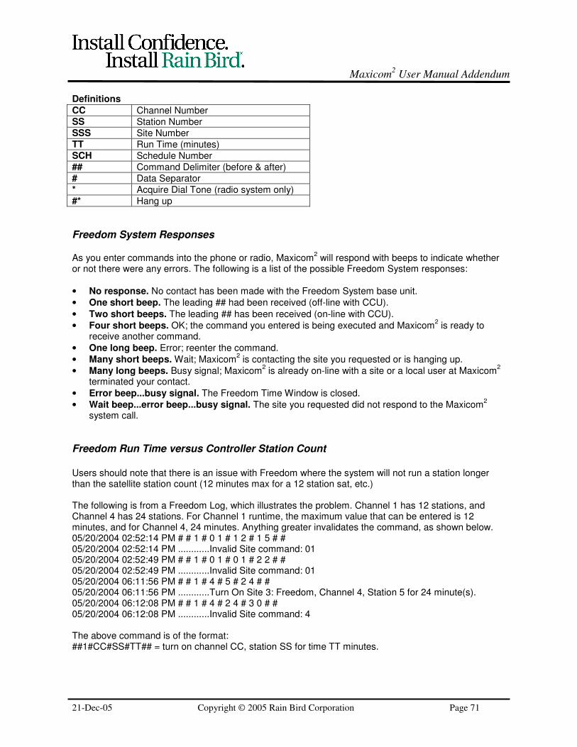
Maxicom2 User Manual Addendum
21-Dec-05 Copyright © 2005 Rain Bird Corporation Page 71
Definitions
CC Channel NumberSS Station NumberSSS Site NumberTT Run Time (minutes)SCH Schedule Number## Command Delimiter (before & after)# Data Separator* Acquire Dial Tone (radio system only)#* Hang up
Freedom System Responses
As you enter commands into the phone or radio, Maxicom2 will respond with beeps to indicate whether
or not there were any errors. The following is a list of the possible Freedom System responses:
• No response. No contact has been made with the Freedom System base unit.
• One short beep. The leading ## had been received (off-line with CCU).
• Two short beeps. The leading ## has been received (on-line with CCU).
• Four short beeps. OK; the command you entered is being executed and Maxicom2 is ready to
receive another command.
• One long beep. Error; reenter the command.
• Many short beeps. Wait; Maxicom2 is contacting the site you requested or is hanging up.
• Many long beeps. Busy signal; Maxicom2 is already on-line with a site or a local user at Maxicom
2
terminated your contact.
• Error beep...busy signal. The Freedom Time Window is closed.
• Wait beep...error beep...busy signal. The site you requested did not respond to the Maxicom2
system call.
Freedom Run Time versus Controller Station Count
Users should note that there is an issue with Freedom where the system will not run a station longerthan the satellite station count (12 minutes max for a 12 station sat, etc.)
The following is from a Freedom Log, which illustrates the problem. Channel 1 has 12 stations, andChannel 4 has 24 stations. For Channel 1 runtime, the maximum value that can be entered is 12minutes, and for Channel 4, 24 minutes. Anything greater invalidates the command, as shown below.05/20/2004 02:52:14 PM # # 1 # 0 1 # 1 2 # 1 5 # #05/20/2004 02:52:14 PM ............Invalid Site command: 0105/20/2004 02:52:49 PM # # 1 # 0 1 # 0 1 # 2 2 # #05/20/2004 02:52:49 PM ............Invalid Site command: 0105/20/2004 06:11:56 PM # # 1 # 4 # 5 # 2 4 # #05/20/2004 06:11:56 PM ............Turn On Site 3: Freedom, Channel 4, Station 5 for 24 minute(s).05/20/2004 06:12:08 PM # # 1 # 4 # 2 4 # 3 0 # #05/20/2004 06:12:08 PM ............Invalid Site command: 4
The above command is of the format:##1#CC#SS#TT## = turn on channel CC, station SS for time TT minutes.

Maxicom2 User Manual Addendum
21-Dec-05 Copyright © 2005 Rain Bird Corporation Page 72
We have the following workaround for the above problem. Instead of using the command formatmentioned above, we can use the following command format:##3#CC#SS#SS#TT## = turn on channel CC, stations SS through SS for time TT minutes.
The normal use of the command is as shown below.05/21/2004 01:36:58 PM # # 3 # 1 # 1 # 6 # 1 5 # #05/21/2004 01:36:58 PM ............Turn On Site 3: Freedom, Channel 1, Station 1 through 6 for 15minute(s).05/21/2004 01:37:39 PM # # 3 # 4 # 5 # 1 0 # 3 0 # #05/21/2004 01:37:39 PM ............Turn On Site 3: Freedom, Channel 4, Station 5 through 10 for 30minute(s).
As a workaround to this issue, we can enter the same Station Number twice, and there is norestriction on the time entered, apart from the fact that it must be between 1 and 99.05/21/2004 01:40:16 PM # # 3 # 1 # 6 # 6 # 2 0 # #05/21/2004 01:40:16 PM ............Turn On Site 3: Freedom, Channel 1, Station 6 for 20 minute(s).

Maxicom2 User Manual Addendum
21-Dec-05 Copyright © 2005 Rain Bird Corporation Page 73
Blank Page