Embed Size (px)
Citation preview

Eva
lua
te: M
AX
69
60
MAX6960 Evaluation Kit/Evaluation System
________________________________________________________________ Maxim Integrated Products 1
19-3851; Rev 0; 10/05
Component List
For pricing, delivery, and ordering information, please contact Maxim/Dallas Direct! at 1-888-629-4642, or visit Maxim’s website at www.maxim-ic.com.
General DescriptionThe MAX6960 evaluation kit (EV kit) provides a provendesign to evaluate the MAX6960 8 x 8 graphic LED tiledisplay driver. The EV kit board contains four MAX6960LED display drivers, four 2.4in 8 x 8 bicolor LED tiles, a4MHz oscillator, and logic buffers. Each MAX6960 EVkit can be cascaded to support up to a total of 20MAX6960 devices. The EV kit also includes Windows®98SE/2000/XP-compatible software, which provides asimple graphical user interface (GUI) for exercising theMAX6960’s features.
The MAX6960 evaluation system (EV system) consistsof a MAX6960 EV kit and a companion MaximCMODUSB serial interface board. The MaximCMODUSB serial interface board allows an IBM-compatible PC to use its USB port to emulate a serialinterface that is compatible with the MAX6960. Orderthe MAX6960EVCMODU for a complete PC-based eval-uation of the MAX6960. Order the MAX6960EVKIT if youalready have a MAX6960 compatible serial interface.
The EV kit includes a preinstalled MAX6960ATH.
Features Four On-Board MAX6960 Devices
Four 2.4in 8 x 8 Bicolor (Red/Green) LED Tiles 4MHz Oscillator
Cascading EV Kits (Up to 5 EV Kit Boards) Buffered Serial Interface
Windows 98SE/2000/XP-Compatible EvaluationSoftware
Proven PC Board Layout Fully Assembled and Tested EV System Includes USB Connectivity
Ordering Information PART TYPE INTERFACE
MAX6960EVKIT EV kit User-supplied MAX6960serial interface
MAX6960EVCMODU EV system CMODUSB board
DESIGNATION QTY DESCRIPTION
C29 1470pF ±10%, 50V X7R ceramiccapacitor (0603)TDK C1608X7R1H471K
C31 1120µF, 4V SP capacitorPanasonic EEFUD0G121R
D1–D4 42.4in 8 x 8 cathode-row bicolorLED displaysLumex LDM-244288MI
J1 1 2 x 20 right-angle female connector
J2 1 2 x 20 right-angle male connector
DESIGNATION QTY DESCRIPTION
C1–C4, C6–C9,C11–C14, C16,C17, C18, C32
1610µF ±20%, 6.3V X5R ceramiccapacitors (0805)TDK C2012X5R0J106M
C20–C26,C30, C33
91µF ±10%, 10V X5R ceramiccapacitors (0603)TDK C1608X5R1A105K
C27 122µF ±20%, 6.3V X5R ceramiccapacitor (1210)TDK C3225X5R0J226M
C28 12.2µF ±20%, 10V X5R ceramiccapacitor (0805)TDK C2012X5R1A225M
Note: The MAX6960 software is included with the MAX6960 EVkit, but is designed for use with the complete EV system. TheEV system (MAX6960EVCMODU) includes both theCMODUSB board and the EV kit. If the Windows software willnot be used, the EV kit board can be purchased without theCMODUSB board.
MAX6960 EV System
MAX6960 EV Kit
PART QTY DESCRIPTION
MAX6960EVKIT 1 MAX6960 EV kit
CMODUSB 1 CMODUSB board
Windows is a registered trademark of Microsoft Corp.

This quick start includes directions for using only oneMAX6960 EV kit board. See the Cascading MAX6960EV Kit Boards section when using more than oneMAX6960 EV kit.
Recommended Equipment
• The MAX6960 EV system MAX6960EVKIT
CMODUSB serial interface board (USB cable included)
• Power supply: +5V at 2.5A per MAX6960 EV kit
• A user-supplied Windows 98SE/2000/XP PC with USB
ProceedureDo not turn on the power until all connections aremade.
1) Verify jumper J1 on the CMODUSB board is con-nected to pins 2-3. This process sets the logic sup-ply to 3.3V.
2) Verify the following MAX6960 EV kit jumpers are inthe default positions:
JU1: (2-3) JU10: (2-3)
JU2: (2-3) JU11: (2-3)
JU3: (1-2) JU12: (Open)
JU4: (2-3) JU13: (1-2)
JU5: (2-3) JU14: (1 only)
JU6: (1-2) JU15: (1-2)
JU7: (2-3) JU16: (1-2)
JU8: (2-3) JU15: (1 only)
JU9: (1-2)
Eva
lua
te: M
AX
69
60
MAX6960 Evaluation Kit/Evaluation System
2 _______________________________________________________________________________________
Component List (continued)
Quick Start
DESIGNATION QTY DESCRIPTION
JU1–JU5,JU7–JU11, JU13
11 3-pin headers
JU6, JU14–JU17 5 2-pin headers
JU12 0PC board trace power jumper,not installed (open)
L1 11.5µH inductor (ISAT = 4A)Sumida CDRH6D28 4762T064
R1, R2, R3, R6,R7
5 1kΩ ±5% resistors (0603)
R4 1 10Ω ±5% resistor (0603)
R5 1 84.5kΩ ±1% resistor (0603)
RP1–RP8 020kΩ potentiometers, top adjust,not installed
U1–U4 4MAX6960ATH (44-pin TQFN, 7mmx 7mm x 0.8mm)
U5–U9, U13 6
Three-state logic buffers(5-pin SOT23)Fairchild SemiconductorNC7SZ126M5X
Topmark7Z26
U10 14MHz silicon oscillator(3-pin SC70)Maxim MAX7375AXR405-T
TopmarkAOR
U11 18-channel multiplexer(16-pin TSSOP)Maxim MAX4617EUE
U12 13A step-down switching regulator(16-pin QSOP)Maxim MAX1831EEE
— 16 Shunts
— 1 MAX6960EVKIT blank PC board
— 1 MAX6960EVKIT SW CD-ROM
MAX6960 EV Kit
MAX6960 EV Kit Files FILE DESCRIPTION
INSTALL.EXE Installs the EV kit files on yourcomputer.
MAX6960.EXE Runs application program.
HELPFILE.HTM Opens the MAX6960 EV kit Helpfile.
TROUBLESHOOTINGUSB.PDF
Opens the USB driver installation helpfile.
FTD2XX.INF USB device driver file.
UNINST.INI Uninstalls the EV kit software.
*.CM2 MAX6960 8-bit write script files.
Component Suppliers
SUPPLIER PHONE WEBSITE
Lumex, Inc. 800-278-5666 www.lumex.com
Panasonic 714-373-7366 www.panasonic.com
Sumida USA 847-545-6700 www.sumida.com
TDK 847-803-6100 www.component.tdk.com
Note: Indicate you are using the MAX6960 when contactingthese component suppliers.

3) Connect the MAX6960 EV kit’s 40-pin female con-nector (J1) to the CMODUSB board’s 40-pin maleconnector (P4).
4) Install the MAX6960 evaluation software on your com-puter by running the INSTALL.EXE program on theinstallation CD-ROM. It is highly recommended to usethe default installation path. If you desire to modifythe default path, do not use a depth of more than twosubdirectories. The program files are copied andicons are created for them in the Windows Startmenu | Programs | Maxim MAX6960 Evaluation Kit.
5) Connect the 5V power supply between the MAX6960EV kit’s +5V and GND pads.Turn on the 5V power sup-ply. Do not connect the USB cable before this step.
6) Connect the included USB cable from the PC to theCMODUSB board. A Building Driver Database win-dow pops up in addition to a New Hardware Foundmessage. If you do not see any window that is similarto the one described above after 30 seconds, removethe USB cable from the CMODUSB board and recon-nect it again. Administrator privileges are required toinstall the USB device driver on Windows 2000 andXP. Refer to the document Troubleshooting USB.PDFincluded with the software for more information.
7) Follow the directions of the Add New HardwareWizard to install the USB device driver. Choose theSearch for the best driver for your device option.Specify the location of the device driver to beC:\Program Files\MAX6960 using the Browse button.
8) Start the MAX6960 EV kit software by opening itsicon in the Windows Start menu | Programs | MaximMAX6960 Evaluation Kit. If the 16-color demo modeis visible, then quick start is complete.
Loading Scripts (Optional)1) Press the Load 8-bit Write Script button on the 8
and 16-bit addr modes tab.
2) Load the script file 1bit_step1_box.cm2 located inthe C:\Program Files\MAX6960 directory.
3) Press the Run 8-bit Write Script (16bytes) button inthe 8-bit Write Script window.
4) Press the Load Next Script button and load thescript file 1bit_step2_box.cm2 located in theC:\Program Files\MAX6960 directory.
5) Press the Run 8-bit Write Script (16bytes) button inthe 8-bit Write Script window.
Detailed Description of SoftwareThe evaluation software’s main window shown in Figure1 displays tabs for 8-bit, 16-bit, and 24-bit addressingmodes as well as individual tabs for each register in theMAX6960’s register address map (0x00 through 0x0F).Table 1 describes the controls that are always presenton the evaluation software’s main window.
The 8 and 16-bit addr modes tab, shown in Figure 1,allows the user to execute 8-bit and 16-bit address modeoperations. The 8-bit address mode is the quickestmethod of updating a plane of display memory in theMAX6960 and is write only. During the 8-bit address
Eva
lua
te: M
AX
69
60
MAX6960 Evaluation Kit/Evaluation System
_______________________________________________________________________________________ 3
Table 1. MAX6960 EV Kit Software Main Window Control DescriptionsCONTROL DESCRIPTION
Allows the user to select the active register tab.
Shows the CMODUSB debugging tools.
Gives access to the Helpfile and the About box.
Automatically sets the global driver devices and the global driver rows registers of the masterMAX6960 to the correct values when cascading boards.
Resets all the registers to the software reset settings.For example:• 2-bits/pixel bicolor mode → Register 0x0D = 0xC1• 4 driver devices (N-1) → Register 0x0E = 0x03• 2 driver rows (N-1) → Register 0x0F = 0x01
Resets all the registers to the IC power-on reset (POR) settings shown in the MAX6960 datasheet.
Displays the CMODUSB connection status. CMOD___ means that it supports both theCMODUSB or CMOD232 boards.
Exits the program.

Eva
lua
te: M
AX
69
60
MAX6960 Evaluation Kit/Evaluation System
4 _______________________________________________________________________________________
mode, data is written to the display memory using indi-rection through the global display indirect address regis-ter. This display indirect address is autoincrementedafter each 8-bit write to allow continuous image datadumps into the plane of display memory in the MAX6960.
The 16-bit address mode is capable of reading or writ-ing command/data bytes to the MAX6960’s registers. A16-bit write can be global (updates all MAX6960s withthe same data) or local (only one MAX6960). A 16-bitread always uses indirection through the global driverindirect address register to select only one MAX6960.Refer to the Register Addressing Modes section of theMAX6960 data sheet for additional information.
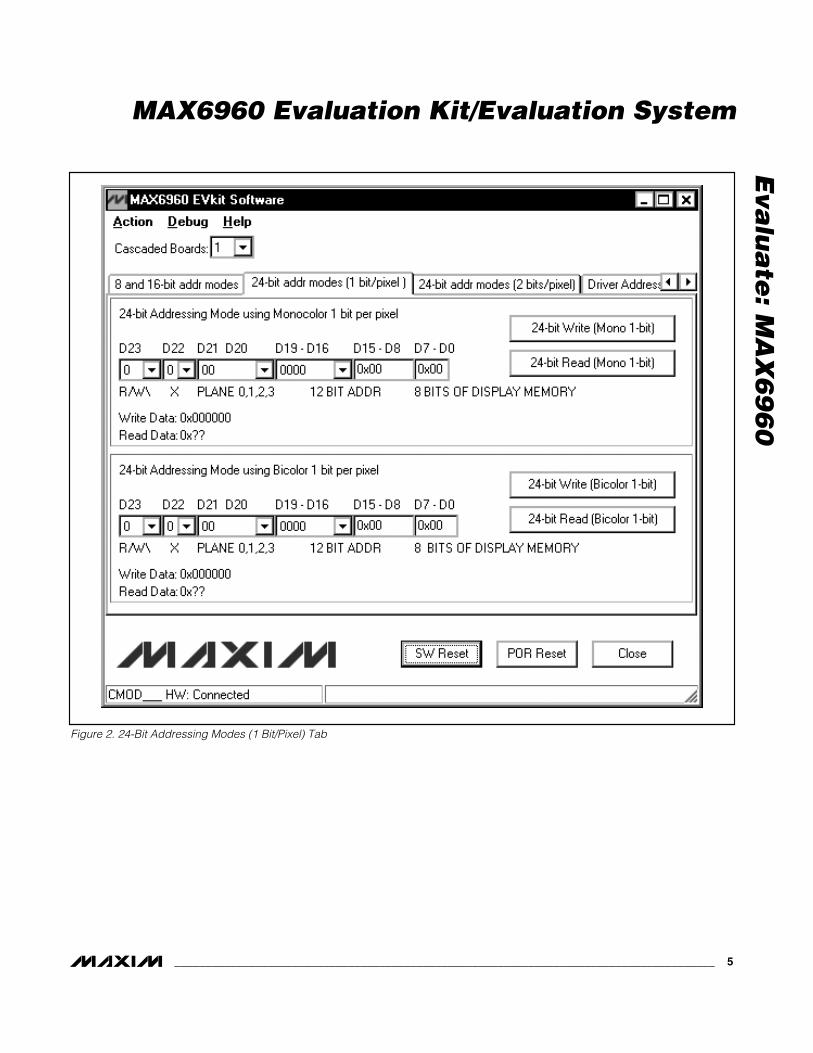
The 24-bit addr modes (1 bit/pixel) tab shown inFigure 2, and the 24-bit addr modes (2 bit/pixel) tabshown in Figure 3, allow the user to execute 24-bitaddress mode operations. A 24-bit operation is alwaysa direct read or write of address/data to the MAX6960’sdisplay memory because the memory address isincluded in the 24-bit operation. Refer to the RegisterAddressing Modes section of the MAX6960 data sheetfor additional information.
Figure 1. MAX6960 Evaluation Software Main Window
Eva
lua
te: M
AX
69
60
MAX6960 Evaluation Kit/Evaluation System
_______________________________________________________________________________________ 5
Figure 2. 24-Bit Addressing Modes (1 Bit/Pixel) Tab

Eva
lua
te: M
AX
69
60
MAX6960 Evaluation Kit/Evaluation System
6 _______________________________________________________________________________________
Figure 3. 24-Bit Addressing Modes (2 Bits/Pixel) Tab

Eva
lua
te: M
AX
69
60
MAX6960 Evaluation Kit/Evaluation System
Detailed Description of HardwareMAX6960 EV System
The MAX6960 EV system is a PC-controlled LED dis-play system consisting of a MAX6960 EV kit and theMaxim CMODUSB serial interface board.
CMODUSB Serial Interface BoardThe CMODUSB serial interface board uses a propri-etary design to provide SPI™- and I2C-compatibleinterfaces to demonstrate various Maxim devices.Maxim reserves the right to change the implementationof this module at any time with no advance notice.
CMODUSB Power SupplyThe CMODUSB board uses a MAX1658 linear regulator.Jumper J1 selects between a 5V or 3.3V system supplyvoltage. Do not plug a wall cube into the P1 power jackbecause power is provided from the USB port.
Table 2. CMODUSB Jumper J1 (SystemSupply Voltage)
MAX6960 EV KitThe MAX6960 EV kit contains four MAX6960 devices(U1–U4), a 16 x 16 dot-matrix display (D1–D4), a step-down voltage regulator (U12), a 4MHz oscillator (U10),and logic buffers (U5–U9, U13). The MAX6960 EV kitrequires a +5V supply (rated for 2.5A per EV kit) and upto five MAX6960 EV kits can be cascaded allowing theuser to evaluate up to 20 MAX6960 devices.
Tables 3 through 19 explain the functionality of eachjumper when using only one MAX6960 EV kit.
Table 3. Digit 0 Current Setting (RISET0—U1)
Table 4. Digit 1 Current Setting (RISET1—U1)
Table 5. Address Data Input (ADDIN—U1)
Table 6. Digit 0 Current Setting (RISET0—U2)
JUMPERSHUNT
POSITIONSYSTEM SUPPLY VOLTAGE
(DVDD)1-2 5V
J12-3* 3.3V
JUMPERSHUNT
POSITIONDESCRIPTION
1-2All U1 digit 0 segment currentsadjustable from 20mA to 40mA.
2-3*All U1 digit 0 segment currents setto 40mA.
JU1
OpenAll U1 digit 0 segment currents setto 20mA.
JUMPERSHUNT
POSITIONDESCRIPTION
1-2All U2 digit 0 segment currentsadjustable from 20mA to 40mA.
2-3*All U2 digit 0 segment currents setto 40mA.
JU4
OpenAll U2 digit 0 segment currents setto 20mA.
JUMPERSHUNT
POSITIONDESCRIPTION
1-2All U1 digit 1 segment currentsadjustable from 20mA to 40mA.
2-3*All U1 digit 1 segment currents setto 40mA.
JU2
OpenAll U1 digit 1 segment currents setto 20mA.
*Default configuration.
JUMPERSHUNT
POSITIONDESCRIPTION
1-2*ADDIN of U1 is connected to+3.3V to indicate the firstMAX6960 device.JU3
2-3See the Cascading MAX6960 EVKit Boards section for details.
_______________________________________________________________________________________ 7
*Default configuration.
*Default configuration.
*Default configuration.
*Make sure the J1 jumper on the CMODUSB board is in the 2-3position when using the MAX6960 EV kit.
SPI is a trademark of Motorola, Inc.

Eva
lua
te: M
AX
69
60
MAX6960 Evaluation Kit/Evaluation System
8 _______________________________________________________________________________________
Table 7. Digit 1 Current Setting(RISET1—U2)
Table 8. U2 New Row Selection(NEWROWBUS—U2)
Table 9. Digit 0 Current Setting (RISET0—U3)
Table 10. Digit 1 Current Setting(RISET1—U3)
Table 11. Address Data Input (ADDIN—U3)
Table 12. Digit 0 Current Setting(RISET0—U4)
JUMPERSHUNT
POSITIONDESCRIPTION
1-2All U3 digit 0 segment currentsadjustable from 20mA to 40mA.
2-3*All U3 digit 0 segment currents setto 40mA.
JU7
OpenAll U3 digit 0 segment currents setto 20mA.
*Default configuration.
JUMPERSHUNT
POSITIONDESCRIPTION
1-2All U3 digit 1 segment currentsadjustable from 20mA to 40mA.
2-3*All U3 digit 1 segment currents setto 40mA.
JU8
OpenAll U3 digit 1 segment currents setto 20mA.
*Default configuration.
JUMPERSHUNT
POSITIONDESCRIPTION
1-2*ADDIN of U3 is connected toNEWROWBUS to start the secondrow of 8 x 8 LED displays.JU9
2-3See the Cascading MAX6960 EVKit Boards section for details.
*Default configuration.
JUMPERSHUNT
POSITIONDESCRIPTION
1-2All U4 digit 0 segment currentsadjustable from 20mA to 40mA.
2-3*All U4 digit 0 segment currents setto 40mA.
JU10
OpenAll U4 digit 0 segment currents setto 20mA.
*Default configuration.
JUMPERSHUNT
POSITIONDESCRIPTION
Short*ADDOUTU2 is connected toNEWROWBUS to start the secondrow of 8 x 8 LED displays.JU6
OpenSee the Cascading MAX6960 EVKit Boards section for details.
*Default configuration.
JUMPERSHUNT
POSITIONDESCRIPTION
1-2All U2 digit 1 segment currentsadjustable from 20mA to 40mA.
2-3*All U2 digit 1 segment currents setto 40mA.
JU5
OpenAll U2 digit 1 segment currents setto 20mA.
*Default configuration.

Eva
lua
te: M
AX
69
60
MAX6960 Evaluation Kit/Evaluation System
_______________________________________________________________________________________ 9
Table 13. Digit 1 Current Setting(RISET1—U4)
Table 14. +5V Power-Line Pass Through
Table 15. Oscillator Buffer Output (OSC)
Table 16. NEWROWBUS Pass Through
Table 17. Put U8 in a Known State
Table 18. LED Open Circuit Test(U1COL1)
Table 19. ADDCLK Pass Through (ADDCLK)
JUMPERSHUNT
POSITIONDESCRIPTION
1-2All U4 digit 1 segment currentsadjustable from 20mA to 40mA.
2-3*All U4 digit 1 segment currents setto 40mA.
JU11
OpenAll U4 digit 1 segment currents setto 20mA.
*Default configuration.
JUMPERSHUNT
POSITIONDESCRIPTION
ShortSee the Cascading MAX6960 EVKit Boards section for details.
JU12Open*
User applies +5V between the+5V and GND pads for the firstMAX6960 EV kit.
*Default configuration.
JUMPERSHUNT
POSITIONDESCRIPTION
Short* Normal operation.
JU16Open
Creates an open circuit on theU1COL1 line of D1 and is used foran LED open circuit test.
*Default configuration.
JUMPERSHUNT
POSITIONDESCRIPTION
ShortSee the Cascading MAX6960 EVKit Boards section for details.
JU17Open*
Do not short this jumper whenusing only one MAX6960 EV kit.
*Default configuration.
JUMPERSHUNT
POSITIONDESCRIPTION
1-2*The MAX7375 silicon oscillator isrouted to U1, U2, U3, and U4.
JU132-3
See the Cascading MAX6960 EVKit Boards section for details.
JUMPERSHUNT
POSITIONDESCRIPTION
ShortSee the Cascading MAX6960 EVKit Boards section for details.
JU14Open*
Do not short this jumper whenusing only one MAX6960 EV kit.
*Default configuration.
JUMPERSHUNT
POSITIONDESCRIPTION
Short*Put U8 in a known state whenusing only one MAX6960 EV kit.
JU15Open
See the Cascading MAX6960 EVKit Boards section for details.
*Default configuration.
*Default configuration.

Cascading MAX6960 EV Kit Boards
The MAX6960 EV kit board was carefully designed tocascade up to five MAX6960 EV kits. Tables 3 through19 explain the functionality of each jumper when usingonly one MAX6960 EV kit and Table 20 shows a sum-mary of all the default settings. The 5V supplyrequires a current capability of 2.5A per MAX6960EV kit. For example, five cascaded MAX6960 EV kitsrequire a 5V supply capable of supplying 12.5A. If thedigit 0 and digit 1 segment current settings arechanged from 40mA to 20mA on all MAX6960 devices,then the current requirement is cut in half. For example,one MAX6960 EV kit would require 1.25A and fiveMAX6960 EV kits would require 6.25A.
Table 20. Using One MAX6960 EV Kit Board
The sections below show the jumper settings for cas-cading two, three, four, and five MAX6960 EV kitboards.
Cascading Two MAX6960 EV Kit BoardsTable 21 shows the jumper settings when cascadingtwo MAX6960 EV kits. The 5V supply requires a currentcapability of 5A when cascading two MAX6960 EV kits.If the digit 0 and digit 1 segment current settings arechanged from 40mA to 20mA on all MAX6960 devicesfor both MAX6960 EV kits, then the current requirementis 2.5A.
Table 21. Cascading Two MAX6960 EV Kit Boards
Eva
lua
te: M
AX
69
60
MAX6960 Evaluation Kit/Evaluation System
10 ______________________________________________________________________________________
MAX6960EV KIT 1
JU1: (2-3)JU2: (2-3)JU3: (1-2)JU4: (2-3)JU5: (2-3)JU6: (1-2)JU7: (2-3)JU8: (2-3)JU9: (1-2)JU10: (2-3)JU11: (2-3)JU12: (Open)JU13: (1-2)JU14: (1 only)JU15: (1-2)JU16: (1-2)JU17: (1 only)
MAX6960EV KIT 1
MAX6960EV KIT 2
JU1: (2-3) JU1: (2-3)JU2: (2-3) JU2: (2-3)JU3: (1-2) JU3: (2-3)JU4: (2-3) JU4: (2-3)JU5: (2-3) JU5: (2-3)JU6: (1 only) JU6: (1-2)JU7: (2-3) JU7: (2-3)JU8: (2-3) JU8: (2-3)JU9: (1-2) JU9: (2-3)JU10: (2-3) JU10: (2-3)JU11: (2-3) JU11: (2-3)JU12: (Open) JU12: (Short)JU13: (1-2) JU13: (2-3)JU14: (1 only) JU14: (1-2)JU15: (1-2) JU15: (1 only)JU16: (1-2) JU16: (1-2)JU17: (1 only) JU17: (1-2)
Note: Bolded text indicates changes from the default settings.

Cascading Three MAX6960 EV Kit BoardsTable 22 shows the jumper settings when cascadingthree MAX6960 EV kits. The 5V supply requires a cur-rent capability of 7.5A when cascading three MAX6960EV kits. If the digit 0 and digit 1 segment current set-tings are changed from 40mA to 20mA on all MAX6960devices for all three MAX6960 EV kits, then the currentrequirement is 3.75A.
Table 22. Cascading Three MAX6960 EVKit Boards
Cascading Four MAX6960 EV Kit BoardsTable 23 shows the jumper settings when cascadingfour MAX6960 EV kits. The 5V supply requires a 10Acurrent capability when cascading four MAX6960 EVkits. If the digit 0 and digit 1 segment current settingsare changed from 40mA to 20mA on all MAX6960devices for all four MAX6960 EV kits, then the currentrequirement is 5A.
Table 23. Cascading Four MAX6960 EVKit Boards
Eva
lua
te: M
AX
69
60
MAX6960 Evaluation Kit/Evaluation System
______________________________________________________________________________________ 11
MAX6960EV KIT 1
MAX6960EV KIT 2
MAX6960EV KIT 3
JU1: (2-3) JU1: (2-3) JU1: (2-3)JU2: (2-3) JU2: (2-3) JU2: (2-3)JU3: (1-2) JU3: (2-3) JU3: (2-3)JU4: (2-3) JU4: (2-3) JU4: (2-3)JU5: (2-3) JU5: (2-3) JU5: (2-3)JU6: (1 only) JU6: (1 only) JU6: (1-2)JU7: (2-3) JU7: (2-3) JU7: (2-3)JU8: (2-3) JU8: (2-3) JU8: (2-3)JU9: (1-2) JU9: (2-3) JU9: (2-3)JU10: (2-3) JU10: (2-3) JU10: (2-3)JU11: (2-3) JU11: (2-3) JU11: (2-3)JU12: (Open) JU12: (Short) JU12: (Short)JU13: (1-2) JU13: (2-3) JU13: (2-3)JU14: (1 only) JU14: (1-2) JU14: (1-2)JU15: (1-2) JU15: (1 only) JU15: (1 only)JU16: (1-2) JU16: (1-2) JU16: (1-2)JU17: (1 only) JU17: (1-2) JU17: (1-2)
MAX6960EV KIT 1
MAX6960EV KIT 2
MAX6960EV KIT 3
MAX6960EV KIT 4
JU1: (2-3) JU1: (2-3) JU1: (2-3) JU1: (2-3)JU2: (2-3) JU2: (2-3) JU2: (2-3) JU2: (2-3)JU3: (1-2) JU3: (2-3) JU3: (2-3) JU3: (2-3)JU4: (2-3) JU4: (2-3) JU4: (2-3) JU4: (2-3)JU5: (2-3) JU5: (2-3) JU5: (2-3) JU5: (2-3)JU6: (1 only) JU6: (1 only) JU6: (1 only) JU6: (1-2)JU7: (2-3) JU7: (2-3) JU7: (2-3) JU7: (2-3)JU8: (2-3) JU8: (2-3) JU8: (2-3) JU8: (2-3)JU9: (1-2) JU9: (2-3) JU9: (2-3) JU9: (2-3)JU10: (2-3) JU10: (2-3) JU10: (2-3) JU10: (2-3)JU11: (2-3) JU11: (2-3) JU11: (2-3) JU11: (2-3)JU12: (Open) JU12: (Short) JU12: (Short) JU12: (Short)JU13: (1-2) JU13: (2-3) JU13: (2-3) JU13: (2-3)JU14: (1 only) JU14: (1-2) JU14: (1-2) JU14: (1-2)JU15: (1-2) J U 1 5 : ( 1 on ly ) J U 1 5 : ( 1 on ly ) J U 1 5 : ( 1 on ly ) JU16: (1-2) JU16: (1-2) JU16: (1-2) JU16: (1-2)JU17: (1 only) JU17: (1-2) JU17: (1-2) JU17: (1-2)
Note: Bolded text indicates changes from the default settings. Note: Bolded text indicates changes from the default settings.

Eva
lua
te: M
AX
69
60 Cascading Five MAX6960 EV Kit Boards
Table 24 shows the jumper settings when cascadingfive MAX6960 EV kits. The 5V supply requires a currentcapability of 12.5A when cascading five MAX6960 EVkits. If the digit 0 and digit 1 segment current settingsare changed from 40mA to 20mA on all MAX6960devices for all five MAX6960 EV kits, then the currentrequirement is 6.25A.
Table 24. Cascading Five MAX6960 EV Kit Boards
MAX6960 EV System TroubleshootingProblem 1: CMOD___ Module Hardware Not Found.See Figure 4.
Solution 1:• Is the red power LED lit on the CMODUSB? If not,
unplug and plug in the USB cable.
• Is the USB cable connected? If not, plug in the USBcable.
• Has the USB driver been installed? If not, refer tostep 6 in the Quick Start section or theTroubleshooting USB.PDF included with the software.
Problem 2: Not all the LEDs light up.
Solution 2:• Are the jumpers in the correct settings? If not, see
the Cascading MAX6960 EV Kit Boards section forcorrect jumper settings.
• Are the global driver devices and global driver rowsregisters configured correctly? If not, select the num-ber of MAX6960 EV kits being used in the CascadedBoards: drop-down menu.
MAX6960 Evaluation Kit/Evaluation System
12 ______________________________________________________________________________________
MAX6960EV KIT 1
MAX6960EV KIT 2
MAX6960EV KIT 3
MAX6960EV KIT 4
MAX6960EV KIT 5
JU 1: ( 2- 3) JU 1: ( 2- 3) JU 1: ( 2- 3) JU 1: ( 2- 3) JU 1: ( 2- 3) JU 2: ( 2- 3) JU 2: ( 2- 3) JU 2: ( 2- 3) JU 2: ( 2- 3) JU 2: ( 2- 3) JU 3: ( 1- 2) J U 3 : ( 2 - 3 ) J U 3 : ( 2 - 3 ) J U 3 : ( 2 - 3 ) J U 3 : ( 2 - 3 ) JU 4: ( 2- 3) JU 4: ( 2- 3) JU 4: ( 2- 3) JU 4: ( 2- 3) JU 4: ( 2- 3) JU 5: ( 2- 3) JU 5: ( 2- 3) JU 5: ( 2- 3) JU 5: ( 2- 3) JU 5: ( 2- 3)
J U 6 : ( 1 on ly )
J U 6 : ( 1 on ly )
J U 6 : ( 1 on ly )
J U 6 : ( 1 on ly )
JU 6: ( 1- 2)
JU 7: ( 2- 3) JU 7: ( 2- 3) JU 7: ( 2- 3) JU 7: ( 2- 3) JU 7: ( 2- 3) JU 8: ( 2- 3) JU 8: ( 2- 3) JU 8: ( 2- 3) JU 8: ( 2- 3) JU 8: ( 2- 3) JU 9: ( 1- 2) J U 9 : ( 2 - 3 ) J U 9 : ( 2 - 3 ) J U 9 : ( 2 - 3 ) J U 9 : ( 2 - 3 ) JU 10: ( 2- 3) JU 10: ( 2- 3) JU 10: ( 2- 3) JU 10: ( 2- 3) JU 10: ( 2- 3) JU 11: ( 2- 3) JU 11: ( 2- 3) JU 11: ( 2- 3) JU 11: ( 2- 3) JU 11: ( 2- 3)
JU 12:( Op en)
J U 1 2 : ( Sh o r t )
J U 1 2 : ( Sh o r t )
J U 1 2 : ( Sh o r t )
J U 1 2 : ( Sh o r t )
JU 13: ( 1- 2) J U 1 3 : ( 2 - 3 ) J U 1 3 : ( 2 - 3 ) J U 1 3 : ( 2 - 3 ) J U 1 3 : ( 2 - 3 )
JU 14:( 1 onl y)
J U 1 4 : ( 1 - 2 ) J U 1 4 : ( 1 - 2 ) J U 1 4 : ( 1 - 2 ) J U 1 4 : ( 1 - 2 )
JU 15: ( 1- 2) J U 1 5 : ( 1 on ly )
J U 1 5 : ( 1 on ly )
J U 1 5 : ( 1 on ly )
J U 1 5 : ( 1 on ly )
JU 16: ( 1- 2) JU 16: ( 1- 2) JU 16: ( 1- 2) JU 16: ( 1- 2) JU 16: ( 1- 2)
JU 17:( 1 onl y) J U 1 7 : ( 1 - 2 ) J U 1 7 : ( 1 - 2 ) J U 1 7 : ( 1 - 2 ) J U 1 7 : ( 1 - 2 )
Figure 4. EV Kit Software Warning Message
Note: Bolded text indicates changes from the default settings.

Eva
lua
te: M
AX
69
60
MAX6960 Evaluation Kit/Evaluation System
______________________________________________________________________________________ 13
RP220kΩ
RP120kΩ
U1ROW1
U1ROW2
U1ROW3
U1ROW4
U1ROW5
U1ROW6
U1ROW7
U1ROW8
ROW1
GND
ROW2
ROW3
ROW4
ROW5
ROW6
ROW7
ROW8
U1COL13
U1ROW1
U1ROW2U1ROW3
U1ROW4
U1ROW5
U1ROW6
U1ROW7
U1ROW8
U1COL12
U1COL11
ADDINROW1
U1COL10
U1COL9
U1COL8
U1COL7
U1COL6
U1COL5
U1COL4
COL13
COL12
COL11
COL10
COL9
COL8
COL7
COL6
COL5
COL4
OSCU
1U2U
3U4
DINB
UFOU
T
DOUT
U1U2
SCLK
BUFO
UT
U1CO
L1
U1CO
L2
U1CO
L3
OSC
GND
GND
GND
DIN
DOUT
SCLK
V+COL1
COL2
COL3
ADDC
LK
ADDI
NU1
ADDI
NU2
U1CO
L16
U1CO
L15
U1CO
L14
ADDC
LK
GND
RISE
T1
RISE
T0
ADDI
N
ADDO
UT
COL1
6V+
COL1
5
COL1
4 V+ U1CO
L1
U1CO
L2
U1CO
L3U1
COL4
U1CO
L5
U1CO
L6
U1CO
L7
U1CO
L8
U1CO
L9
U1CO
L10
U1CO
L11
U1CO
L12
U1CO
L13
U1CO
L14
U1CO
L15
U1CO
L16
1
1
2
2
JU1
JU2
3
3
12
3
12
3
12
3
4
5
6
7
8
9
10
11
33
32
31
30
29
28
27
26
25
24
23
12 13 14 15 16 17 18 19 20 21 22
44 43 42 41 40 39 38 37 36 35 34
+3.3V
+3.3V
C410µF
C110µF
C210µF
C310µF
+3.3V +3.3V
JU16
JU3
+3.3V
1
2
3
MAX6960
U1 D1LDM-244288MI
V+
23 20 17 14 2 5 8 11
24 21 18 15 1 4 7 10
2219
16
133
6
9
12
RESE
TRE
SET
CSBU
FOUT
CS
Figure 5. MAX6960 EV Kit Schematic (Sheet 1 of 6)

Eva
lua
te: M
AX
69
60
MAX6960 Evaluation Kit/Evaluation System
14 ______________________________________________________________________________________
RP420kΩ
RP320kΩ
U2ROW1
U2ROW2
U2ROW3
U2ROW4
U2ROW5
U2ROW6
U2ROW7
U2ROW8
ROW1
GND
ROW2
ROW3
ROW4
ROW5
ROW6
ROW7
ROW8
U2COL13
U2ROW1
U2ROW2U2ROW3
U2ROW4
U2ROW5
U2ROW6
U2ROW7
U2ROW8
U2COL12
U2COL11
NEWROWBUS
U2COL10
U2COL9
U2COL8
U2COL7
U2COL6
U2COL5
U2COL4
COL13
COL12
COL11
COL10
COL9
COL8
COL7
COL6
COL5
COL4
OSCU
1U2U
3U4
DINB
UFOU
T
DOUT
U1U2
SCLK
BUFO
UT
U2CO
L1
U2CO
L2
U2CO
L3
OSC
GND
GND
GND
DIN
DOUT
SCLK
V+COL1
COL2
COL3
ADDC
LK
ADDI
NU2
ADDO
UTU2
U2CO
L16
U2CO
L15
U2CO
L14
ADDC
LK
GND
RISE
T1
RISE
T0
ADDI
N
ADDO
UT
COL1
6V+
COL1
5
COL1
4 V+ U2CO
L1
U2CO
L2
U2CO
L3U2
COL4
U2CO
L5
U2CO
L6
U2CO
L7
U2CO
L8
U2CO
L9
U2CO
L10
U2CO
L11
U2CO
L12
U2CO
L13
U2CO
L14
U2CO
L15
U2CO
L16
1
1
2
2
JU4
JU5
3
3
12
3
1
2
3
1
2
3
4
23 20 17 14 2 5 8 11
24 21 18 15 1 4 7 10
5
6
7
8
9
10
11
33
2219
16
133
6
9
12
32
31
30
29
28
27
26
25
24
23
12 13 14 15 16 17 18 19 20 21 22
44 43 42 41 40 39 38 37 36 35 34
+3.3V
+3.3V
C910µF
C610µF
C710µF
C810µF
+3.3V +3.3V
JU6
MAX6960
U2 D2LDM-244288MI
V+
RESE
TRE
SET
CSBU
FOUT
CS
Figure 5. MAX6960 EV Kit Schematic (Sheet 2 of 6)

Eva
lua
te: M
AX
69
60
MAX6960 Evaluation Kit/Evaluation System
______________________________________________________________________________________ 15
RP620kΩ
RP520kΩ
U3ROW1
U3ROW2
U3ROW3
U3ROW4
U3ROW5
U3ROW6
U3ROW7
U3ROW8
ROW1
GND
ROW2
ROW3
ROW4
ROW5
ROW6
ROW7
ROW8
U3COL13
U3ROW1
U3ROW2U3ROW3
U3ROW4
U3ROW5
U3ROW6
U3ROW7
U3ROW8
U3COL12
U3COL11
ADDINROW2NEWROWBUS
U3COL10
U3COL9
U3COL8
U3COL7
U3COL6
U3COL5
U3COL4
COL13
COL12
COL11
COL10
COL9
COL8
COL7
COL6
COL5
COL4
OSCU
1U2U
3U4
DINB
UFOU
T
DOUT
U3U4
SCLK
BUFO
UT
U3CO
L1
U3CO
L2
U3CO
L3
OSC
GND
GND
GND
DIN
DOUT
SCLK
V+COL1
COL2
COL3
ADDC
LK
ADDI
NU3
ADDI
NU4
U3CO
L16
U3CO
L15
U3CO
L14
ADDC
LK
GND
RISE
T1
RISE
T0
ADDI
N
ADDO
UT
COL1
6V+
COL1
5
COL1
4 V+ U3CO
L1
U3CO
L2
U3CO
L3U3
COL4
U3CO
L5
U3CO
L6
U3CO
L7
U3CO
L8
U3CO
L9
U3CO
L10
U3CO
L11
U3CO
L12
U3CO
L13
U3CO
L14
U3CO
L15
U3CO
L16
1
11
2
2 2JU7
JU8
3
3
3
12
3
1
2
3
1
2
3
4
23 20 17 14 2 5 8 11
24 21 18 15 1 4 7 10
5
6
7
8
9
10
11
33
2219
16
133
6
9
12
32
31
30
29
28
27
26
25
24
23
12 13 14 15 16 17 18 19 20 21 22
44 43 42 41 40 39 38 37 36 35 34
+3.3V
+3.3V
C1410µF
C1110µF
C1210µF
C1310µF
+3.3V +3.3V
JU9
MAX6960
U3 D3LDM-244288MI
V+
RESE
TRE
SET
CSBU
FOUT
CS
Figure 5. MAX6960 EV Kit Schematic (Sheet 3 of 6)
Eva
lua
te: M
AX
69
60
MAX6960 Evaluation Kit/Evaluation System
16 ______________________________________________________________________________________
RP820kΩ
RP720kΩ
U4ROW1
U4ROW2
U4ROW3
U4ROW4
U4ROW5
U4ROW6
U4ROW7
U4ROW8
ROW1
GND
ROW2
ROW3
ROW4
ROW5
ROW6
ROW7
ROW8
U4COL13
U4ROW1
U4ROW2U4ROW3
U4ROW4
U4ROW5
U4ROW6
U4ROW7
U4ROW8
U4COL12
U4COL11
U4COL10
U4COL9
U4COL8
U4COL7
U4COL6
U4COL5
U4COL4
COL13
COL12
COL11
COL10
COL9
COL8
COL7
COL6
COL5
COL4
OSCU
1U2U
3U4
DINB
UFOU
T
DOUT
U3U4
SCLK
BUFO
UT
U4CO
L1
U4CO
L2
U4CO
L3
OSC
GND
GND
GND
DIN
DOUT
SCLK
V+COL1
COL2
COL3
ADDC
LK
ADDI
NU4
ADDO
UTU4
U4CO
L16
U4CO
L15
U4CO
L14
ADDC
LK
GND
RISE
T1
RISE
T0
ADDI
N
ADDO
UT
COL1
6V+
COL1
5
COL1
4 V+ U4CO
L1
U4CO
L2
U4CO
L3U4
COL4
U4CO
L5
U4CO
L6
U4CO
L7
U4CO
L8
U4CO
L9
U4CO
L10
U4CO
L11
U4CO
L12
U4CO
L13
U4CO
L14
U4CO
L15
U4CO
L16
1
1
2
2
JU10
JU11
3
3
12
3
1
2
3
1
2
3
4
23 20 17 14 2 5 8 11
24 21 18 15 1 4 7 10
5
6
7
8
9
10
11
33
2219
16
133
6
9
12
32
31
30
29
28
27
26
25
24
23
12 13 14 15 16 17 18 19 20 21 22
44 43 42 41 40 39 38 37 36 35 34
+3.3V
+3.3V
C1810µF
C3210µF
C1610µF
C1710µF
+3.3V +3.3V
MAX6960
U4 D4LDM-244288MI
V+
RESE
TRE
SET
CSBU
FOUT
CS
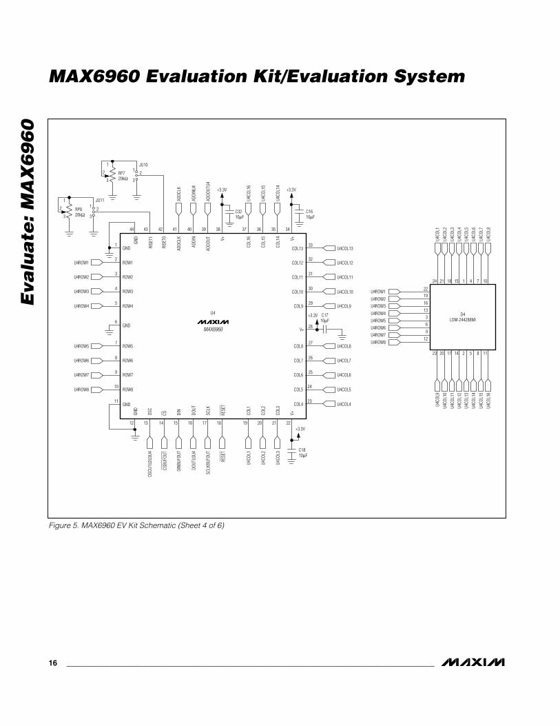
Figure 5. MAX6960 EV Kit Schematic (Sheet 4 of 6)

Eva
lua
te: M
AX
69
60
MAX6960 Evaluation Kit/Evaluation System
______________________________________________________________________________________ 17
Figure 5. MAX6960 EV Kit Schematic (Sheet 5 of 6)
J1-1
J1-2
J1-3
J1-4
J1-7
J1-8
J1-4
0JU
14
JU13
JU15
R6 1kΩ
J1-3
9
J1-3
7
J1-3
6
J1-3
5
J1-3
3
J1-3
1
J1-3
0
J1-2
7
J1-1
2
JU12
+3.3
V
DOUT
DIN
SCLK
SCLK
BUFO
UT
DINB
UFOU
T
ADDI
NROW
1
CSBU
FOUT
RESE
TAD
DINR
OW2
O_OS
CBUF
2IN
O_OS
CBUF
2OUT
OSCU
1U2U
3U4
O_OS
CBUF
1OUT
O_DO
UTUX
DOUT
U3U4
DOUT
U1U2 AD
DOUT
U2
ADDO
UTU4
NEW
ROW
BUS
CS
C20
1µF
JU17
5
24
31
ADDC
LK
J1
+5V
+3.3
V
U5
5
24
31U1
3U1
1
5
24
31U6 5
24
31U7 5
24
3
3
1
1V+
U8
C23
1µF
C24
1µF
C22
1µF
C21
1µF
C33
1µF
C26
1µF
R7 1kΩ
C25
1µF
R1 1kΩ
R2 1kΩ
R3 1kΩ
5
22
2
13
14151215243
X1X0
GND
EN
X2X3X4X5X6X7XV CC
N.C. B
10 91116
7
+5V
A C
86
4
3
3
1
1
U9
GND
+3.3
V
+3.3
V
+3.3
V
CLOC
K
+3.3
V+3.3
V
+3.3
V+3
.3V
U10
MAX
7375
J2-1
J2-2
J2-3
J2-4
J2-7
J2-8
J2-1
2
J2-2
7J2
-30
J2-3
6
J2-3
7
J2-3
9
J2-4
0
J2-3
1
J2-3
3
J2-3
5
J2
MAX
4617
40-P
IN 2
x 20
RIG
HT A
NGLE
FE
MAL
E CO
NNEC
TOR
40-P
IN 2
x 20
RIG
HT A
NGLE
M
ALE
CONN
ECTO
R
+3.3
V
RESE
T
Eva
lua
te: M
AX
69
60
MAX6960 Evaluation Kit/Evaluation System
18 ______________________________________________________________________________________
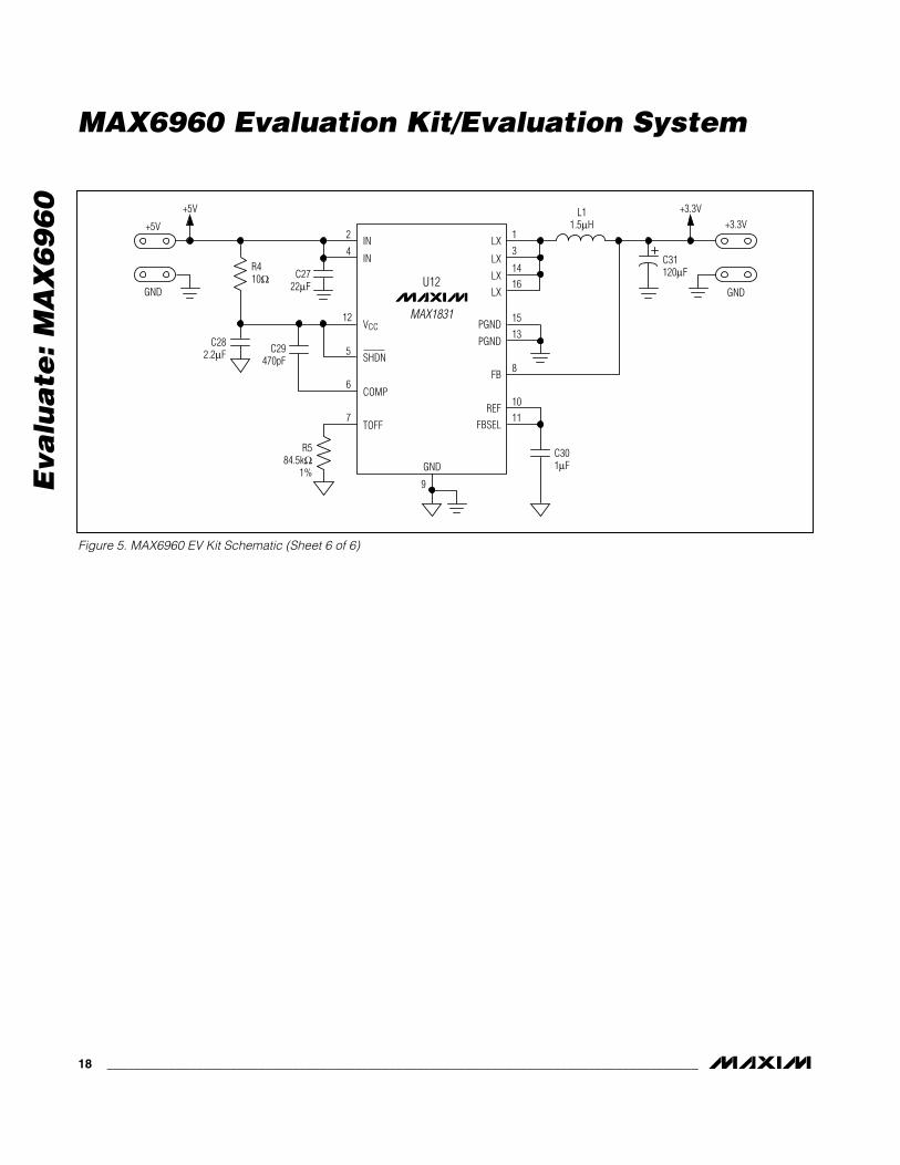
Figure 5. MAX6960 EV Kit Schematic (Sheet 6 of 6)
+5V
+5V
GND
GND
GND
C282.2µF C29
470pF
C301µF
C31120µF
L11.5µH +3.3V
+3.3V
R584.5kΩ
1%
C2722µF
R410Ω
2 IN LX
LX
LX
LX
FB
PGND
PGND
REFFBSEL
IN
VCC
SHDN
COMP
TOFF
1
3
1416
15
13
8
1011
4
12
5
6
7
9
MAX1831
U12

Eva
lua
te: M
AX
69
60
MAX6960 Evaluation Kit/Evaluation System
______________________________________________________________________________________ 19
Figure 6. MAX6960 EV Kit Component Placement Guide—Component Side
Eva
lua
te: M
AX
69
60
MAX6960 Evaluation Kit/Evaluation System
20 ______________________________________________________________________________________
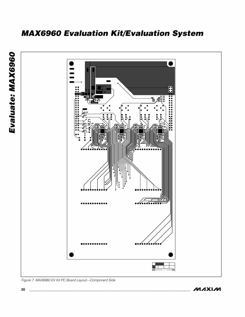
Figure 7. MAX6960 EV Kit PC Board Layout—Component Side

Eva
lua
te: M
AX
69
60
MAX6960 Evaluation Kit/Evaluation System
______________________________________________________________________________________ 21
Figure 8. MAX6960 EV Kit PC Board Layout—Inner Layer 2 (GND)

Eva
lua
te: M
AX
69
60
MAX6960 Evaluation Kit/Evaluation System
22 ______________________________________________________________________________________
Figure 9. MAX6960 EV Kit PC Board Layout—Inner Layer 3 (VCC)
Eva
lua
te: M
AX
69
60
MAX6960 Evaluation Kit/Evaluation System
______________________________________________________________________________________ 23
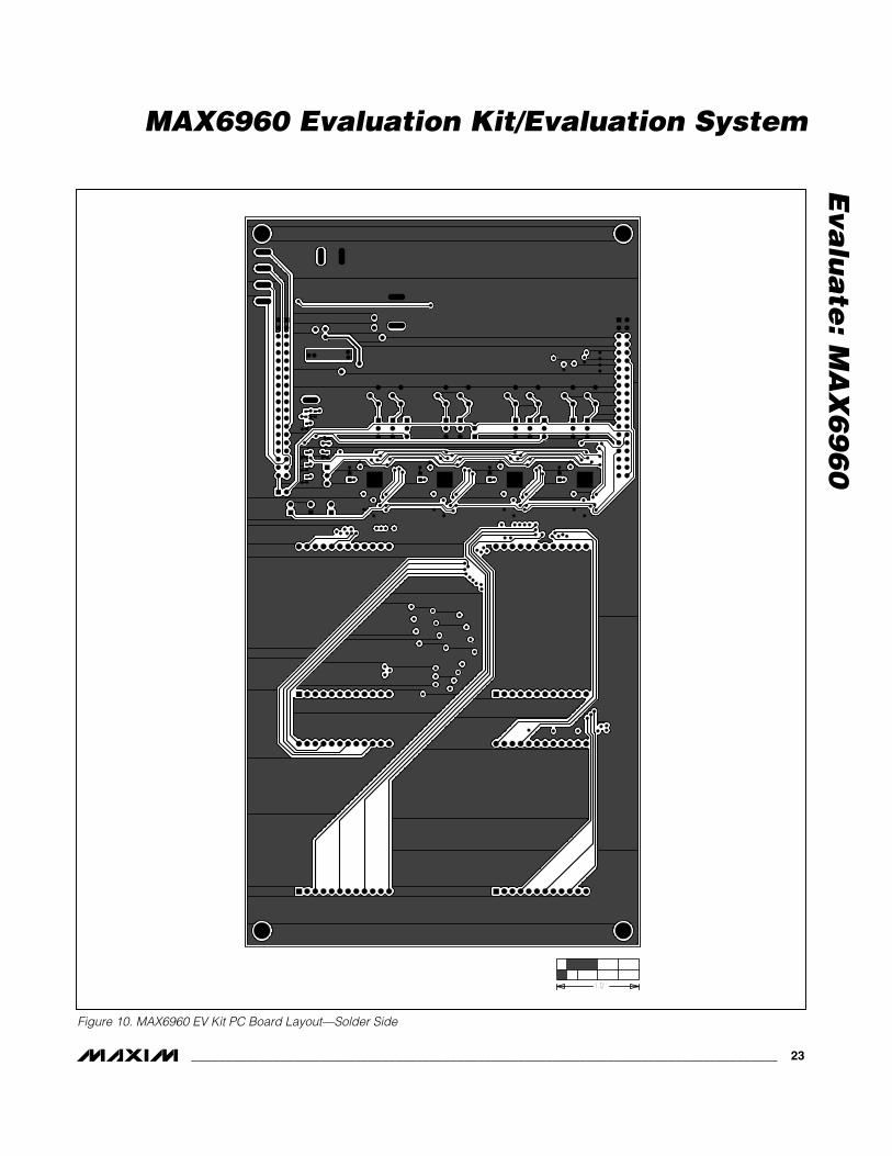
Figure 10. MAX6960 EV Kit PC Board Layout—Solder Side

Maxim cannot assume responsibility for use of any circuitry other than circuitry entirely embodied in a Maxim product. No circuit patent licenses areimplied. Maxim reserves the right to change the circuitry and specifications without notice at any time.
24 ____________________Maxim Integrated Products, 120 San Gabriel Drive, Sunnyvale, CA 94086 408-737-7600
Eva
lua
te: M
AX
69
60
MAX6960-63 Evaluation Kit/Evaluation System
Figure 11. MAX6960 EV Kit Component Placement Guide—Solder Side