Embed Size (px)
Citation preview
Materials Design - Towards a Functionally Graded Electrical Conductor1
S. Satapathy, K. Hsieh, and C. Persad
Institute for Advanced Technology The University of Texas at Austin
3925 West Braker, Austin, TX -78759 Email: [email protected]
Abstract In this study, we discuss functionally graded (FG) materials as pulsed electrical conductors. These conductors can be designed to be more efficient and longer lasting by applying numerical modeling tools. One focus is on limiting the thermal fatigue damage in conductors caused by very high temperatures that develop during pulse heating. We have quantified the effect of various grading functions on the pulsed Joule heating generated and the peak temperature experienced in the conductors of an electromagnetic launcher by using a 1D numerical code and a state of the art 3D coupled finite element code, EMAP3D. Because FG materials incorporate applications-tailored compositions, structures, and dimensions, smoothly graded properties in lateral and longitudinal cross sections are obtainable. The Solid Freeform Fabrication (SFF) processing approach allows for architectures with a series of important features. These features include the selective use of high efficiency conducting materials in the core, preconditioned conductor/structure interfaces, and built-in features for enhanced cooling where necessary. Introduction Many electrical conductor materials require designs that minimize Joule heating losses. At the same time, the conductor may require specific structural features to match the spacing of support structures. An example is the design of conductors for power transmission. For example, for overhead power transmission lines, the traditional materials solution is to use steel-cored aluminum alloy conductorsi. More sophisticated underground conductor arrangements use superconducting cable based on the new high temperature ceramic superconductors. A wide spectrum of customized cable materials and constructions has been developed. Installation costs for these types of conductors vary widely depending upon the locality. An extreme example is the recent 350-meter superconducting cable installation with a cost of $26M(USD). Superconducting cable alone can cost $1,500 per kA per meter compared to $25 per kA per meter, the cost of copper cableii.
Functionally graded copper-based materials may offer an affordable alternative to costly underground conductor arrangements that use superconducting cable. One can
1 This research was supported by the Office of Naval Research MURI Grant # N00014-04-1-0599 RQ –M.
175
envisage an integrated underground conductor laying operation in which a cable-trenching unit is coupled to an SFF-based cable fabrication unit. Trenching, cable-laying, and trench back-filling operations can thus be efficiently integrated. The cable can be designed and armored to meet specific local terrain and load handling requirements. All power transmission systems must be designed for tolerance of electrical fault conditions. During a fault, a solidly grounded system has high values of current (>10kA). Similarly, the conductors in electromagnetic launchers experience severe skin heating due to the limited diffusion time during the short (10ms) pulses. The surface temperature on such conductors can rise to near melting temperature, while the bulk temperature in the interior is comparatively much lower. This inhomogeneity in temperature distribution results in a severe temperature gradient near surface region that leads to higher thermal stresses. Thus, in addition to lowering the conductor skin strength due to elevation in
(A) Complex HVDC conductor pair
X=0 X=l
ρ1 ρ2
Inter-conductor gap
(B) Simplified rectangular conductor pairs
Figure 1: Realistic and simplified conductor pairs.
Out
er S
urfa
ce Inner Surface
176
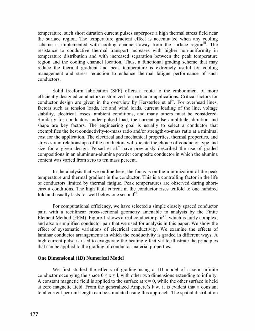
temperature, such short duration current pulses superpose a high thermal stress field near the surface region. The temperature gradient effect is accentuated when any cooling scheme is implemented with cooling channels away from the surface regioniii. The resistance to conductive thermal transport increases with higher non-uniformity in temperature distribution and with increased separation between the peak temperature region and the cooling channel location. Thus, a functional grading scheme that may reduce the thermal gradient and peak temperature is extremely useful for cooling management and stress reduction to enhance thermal fatigue performance of such conductors. Solid freeform fabrication (SFF) offers a route to the embodiment of more efficiently designed conductors customized for particular applications. Critical factors for conductor design are given in the overview by Hersterlee et aliv. For overhead lines, factors such as tension loads, ice and wind loads, current loading of the line, voltage stability, electrical losses, ambient conditions, and many others must be considered. Similarly for conductors under pulsed load, the current pulse amplitude, duration and shape are key factors. The engineering goal is usually to select a conductor that exemplifies the best conductivity-to-mass ratio and/or strength-to-mass ratio at a minimal cost for the application. The electrical and mechanical properties, thermal properties, and stress-strain relationships of the conductors will dictate the choice of conductor type and size for a given design. Persad et al.v have previously described the use of graded compositions in an aluminum-alumina powder composite conductor in which the alumina content was varied from zero to ten mass percent. In the analysis that we outline here, the focus is on the minimization of the peak temperature and thermal gradient in the conductor. This is a controlling factor in the life of conductors limited by thermal fatigue. Peak temperatures are observed during short-circuit conditions. The high fault current in the conductor rises tenfold to one hundred fold and usually lasts for well below one secondvi. For computational efficiency, we have selected a simple closely spaced conductor pair, with a rectilinear cross-sectional geometry amenable to analysis by the Finite Element Method (FEM). Figure-1 shows a real conductor pairvii, which is fairly complex, and also a simplified conductor pair that we used for analysis in this paper. We show the effect of systematic variations of electrical conductivity. We examine the effects of laminar conductor arrangements in which the conductivity is graded in different ways. A high current pulse is used to exaggerate the heating effect yet to illustrate the principles that can be applied to the grading of conductor material properties. One Dimensional (1D) Numerical Model
We first studied the effects of grading using a 1D model of a semi-infinite conductor occupying the space 0 ≤ x ≤ l, with other two dimensions extending to infinity. A constant magnetic field is applied to the surface at x = 0, while the other surface is held at zero magnetic field. From the generalized Ampere’s law, it is evident that a constant total current per unit length can be simulated using this approach. The spatial distribution
177
of the current varies within the body with time. The equations for thermal and magnetic diffusion are,
tT
kq
xT
xk
kxT g
∂∂
α∂∂
∂∂
∂∂ 11
2
2
=++ (1)
∂ 2 H∂x2 +
1ρ∂ρ∂x
∂H∂x
=1k0
∂H∂t
(2)
where k is thermal conductivity, α is the thermal diffusivity, ρ is electrical resistivity, k0 is magnetic diffusivity, and H is the magnetic field intensity. The heat source qg is supplied by the Joule heating which is proportional to the square of the gradient of the magnetic field intensity, i.e.
2
⎟⎠⎞
⎜⎝⎛=
dxdHqg ρ (3)
Equation (3) strongly couples equations (1) and (2). The magnetic boundary conditions specified are the time-varying magnetic fields at inner and outer boundaries. H(0) = H0 (t) , and H(x = L) = 0 (4)
H0(t) is assumed to be a step function with an amplitude of 22 x 106 H corresponding to a total current of 1 MA flowing through a 45 mm high conductor. This corresponds to an inter-conductor magnetic field of about 28 T. An analytical solution to the above boundary value problem is possible using various transformation techniques. However, such solutions are cumbersome and often require a numerical evaluation anyway. We thus used a finite difference numerical schemeviii to solve this boundary value problem. Grading Schemes In the calculations, the conductor material is graded by using the following function,
(5)
where ρ1 and ρ2 are the electrical resistivities of the inner and the outer surfaces, respectively. The exponent, n, governs the rapidity of the functional variation. The resistivity inside the conductor varies continuously as indicated in Equation (5), except in
( )n
lx⎟⎠⎞
⎜⎝⎛−+= 121 ρρρρ
178

one case where a bi-metallic conductor was simulated with discrete values of resistivity. Figure 2 shows the spatial variation of the resistivity with conductor depth for the resistivity ratio, ρ1/ρ2=10 for various values for the exponent, n in the range 0.01 to 1.0. It should be noted that this functional form is used in this paper for illustration purpose, and other functional forms can be easily incorporated into our analysis.
It is clear that for small values of the exponent, n, the grading function approximates an exponential drop in resistivity which is attainable in a diffusive mass transfer process. In all calculations, the base conductor material (on one of the surfaces) is taken to be pure Copper. The local resistivity is graded up or down from this base material towards the other surface. Results A simple analysis shows that the effect of resistive grading is minimal, at least to the first order, on the heat generated. Consider a one-dimensional diffusion into a solid flat conductor. The diffusion depth is given by,
µρδ tC= (6)
where C is a constant depending on the definition of the diffusion depth. Assuming that the current resides in this diffusion thickness, the current density is given by
( ) ( )tC
hIhIjρµ
δ//
== (7)
0
0.2
0.4
0.6
0.8
1
1.2
0 0.2 0.4 0.6 0.8 1
Fractional distance from the inner surface, x/ l
Res
istiv
ity R
atio
n=0.01n=0.05n=0.1n=0.5n=1Bi-layer
X= X=l
ρ1 ρ2
-
Figure-2: Grading functions used in the simulations.
179
The joule heating is given by,
( )222
/I hq j
C tµ
ρ= = (8)
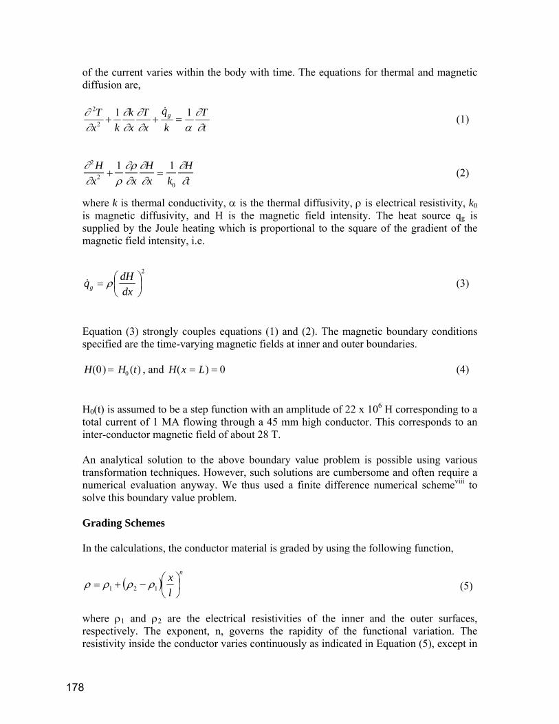
that shows q to be independent of the resistivity. However, such a simple analysis does not account for the functional dependence of the properties on the spatial variable, and hence is flawed as shown by following figures. In figure-3, we have plotted the heat generated by conductors constructed according to various grading schemes. The values are a snapshot at 5 ms after the initiation of the current pulse. For the value of the resistivity ratio less than unity, the most resistive layer is farthest from the gap between the conductors. Similarly for the resistivity ratios greater than unity, the most resistive layer is on the surfaces facing the gap. In all cases, the minimum heat generated is for all-copper case. As the exponent, n, is reduced towards zero, the heat generated approaches the all-copper case for resistivity ratios greater than unity.
Figure-4 shows the surface temperature at the gap facing surfaces for various cases at 5 ms. Interestingly, even though the heat generation is higher for graded materials, the gap-facing surface temperature, which should be close to the peak temperature, reduces with decreasing values of the exponent. The maximum reduction in this peak temperature value occurs for the grading scheme described for n=0.01 in Equation 5. For n=0.01, the peak temperature is reduced by 25% compared to all-copper case.
Conductor Heating
0.E+00
1.E+05
2.E+05
3.E+05
4.E+05
5.E+05
6.E+05
7.E+05
0 2 4 6 8 10
Resistivity Ratio (Inner/Outer)
Hea
t Dep
osite
d (J
/m)
Bi n=0.01n=0.05n=0.1n=0.5n=1
Figure-3: Heating generated by different grading schemes.
180

In figure-5, we have plotted the surface temperatures at 1 ms. This figure shows that at early times the reduction in temperature is larger. It is reduced by 39% for n=0.05 compared to n=1.
Figure-6 shows the temperature distribution for n=0.01 for various resistivity ratios. It is evident that conductor gradings with higher resistivity ratios lower the peak temperature, and push the spatial location of the highest temperature away from the conductor surface. Thus, by appropriate grading of resistivity, the peak temperature location can be pushed inwards towards more easily engineered cooling channel locations. Here, we have used a single monotonic functional form for resistivity variation. A different functional form, perhaps of non-monotonic nature, may provide even better
500
520
540
560
580
600
620
640
660
680
700
0 1 2 3 4 5 6 7 8 9 10
Resistivity Ratio
Tem
pera
ture
, K
Bin=0.01n=0.05n=0.1n=0.5n=1
Figure-4: Temperatures at the conductor surfaces facing
the conductor gap at t=5ms for six cases
400
450
500
550
600
650
700
0.00 2.00 4.00 6.00 8.00 10.00 12.00
Resistivity Ratio
Tem
pera
ture
, K
10.05Bi
Figure-5: Temperatures at the conductor surfaces facing the
conductor gap at t=1ms for three cases.
181

control of coolant flow channel location for more efficient thermal management of such conductors.
EMAP3D Calculations
The Institute of Advanced Technology has developed a state of the art computational code, EMAP3Dix,x for solution of coupled electromagnetic, thermal and mechanical fields. It allows for relative motion between conductors, and incorporates both finite element and boundary element methods to produce highly accurate solution. The code has been parallelized for use in PC node clusters for fast computation of large problems.
Figure 6: Temperature distribution for n=0.01 and various resistivity ratios indicated in the legend box. Note that the peak temperature is lowered and its location shifts with higher resistivity ratio.
182
The electromagnetic problem is inherently three-dimensional because changing electric field generates changing magnetic fields and vice versa, and the associated electromagnetic waves are known to travel through all forms of matter as well as in vacuum. However, carrying out 3D computations in unbounded volumes is cumbersome and time consuming. We have shown beforexi that thermal characteristics of electromagnetic launchers can be well approximated by the 1D code, where trends are similar and amplitudes are close to those from 3D solutions. We therefore chose to carry out a 2D computation to ascertain the fidelity of the results obtained from our 1D analysis, and to gain additional insight into the field distributions in the cross-section of the conductor. It must be noted that these 2D results would be a close representation of the actual 3D fields at the l = 0 end of the conductor pair.
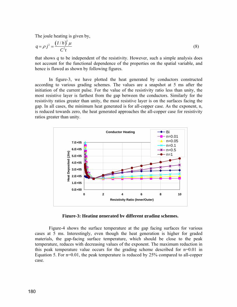
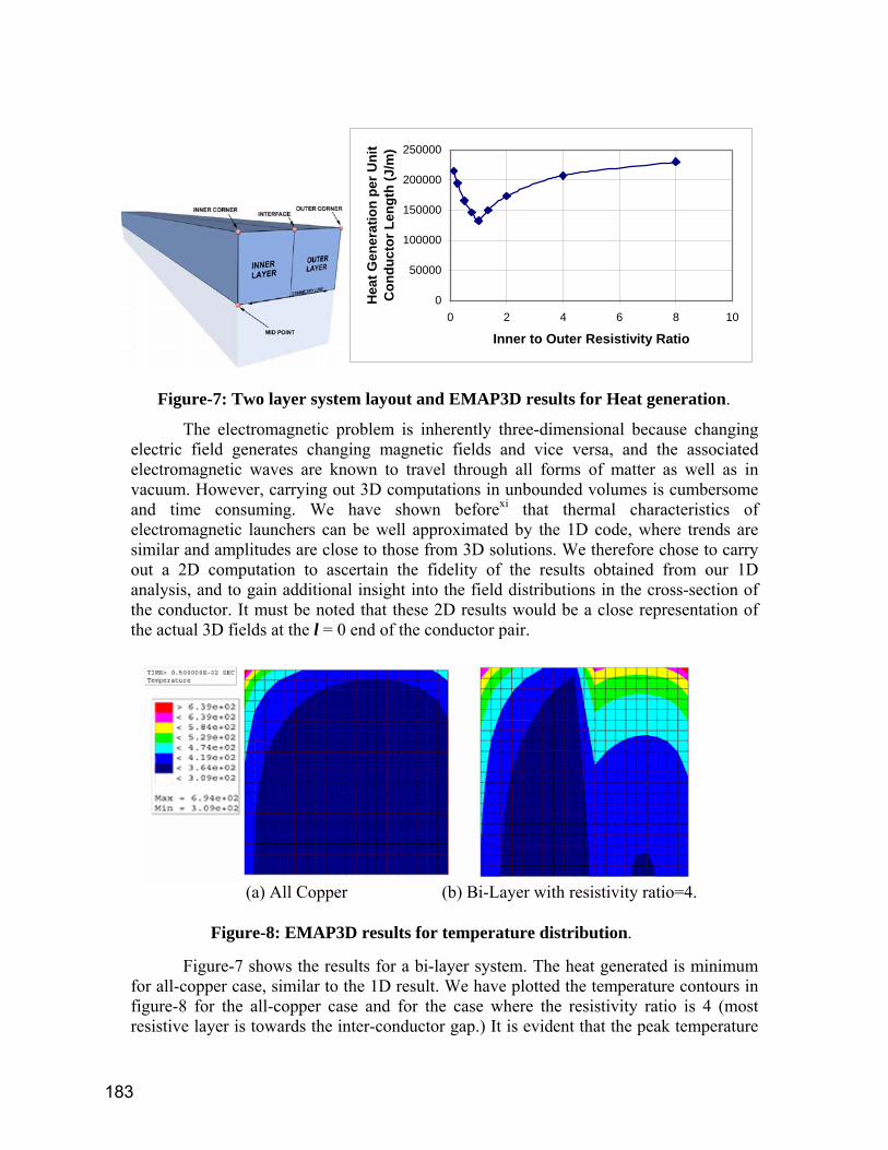
Figure-7 shows the results for a bi-layer system. The heat generated is minimum for all-copper case, similar to the 1D result. We have plotted the temperature contours in figure-8 for the all-copper case and for the case where the resistivity ratio is 4 (most resistive layer is towards the inter-conductor gap.) It is evident that the peak temperature
0
50000
100000
150000
200000
250000
0 2 4 6 8 10
Inner to Outer Resistivity Ratio
Hea
t Gen
erat
ion
per U
nit
Con
duct
or L
engt
h (J
/m)
Figure-7: Two layer system layout and EMAP3D results for Heat generation.
(a) All Copper (b) Bi-Layer with resistivity ratio=4.
Figure-8: EMAP3D results for temperature distribution.
183
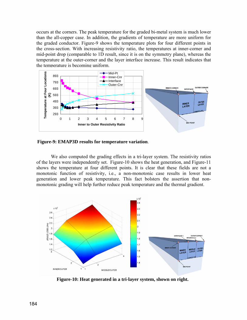
occurs at the corners. The peak temperature for the graded bi-metal system is much lower than the all-copper case. In addition, the gradients of temperature are more uniform for the graded conductor. Figure-9 shows the temperature plots for four different points in the cross-section. With increasing resistivity ratio, the temperatures at inner-corner and mid-point drop (comparable to 1D result, since it is on the symmetry plane), whereas the temperature at the outer-corner and the layer interface increase. This result indicates that the temperature is becoming uniform.
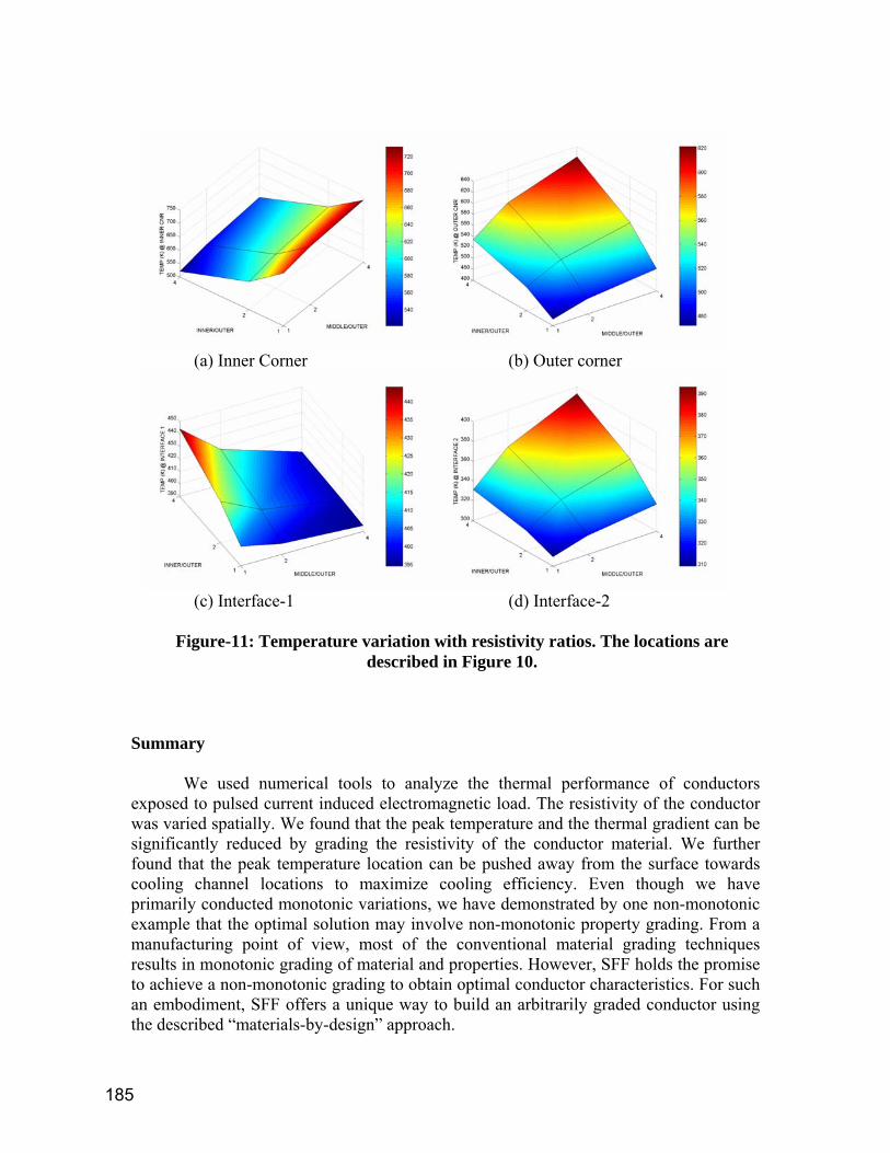
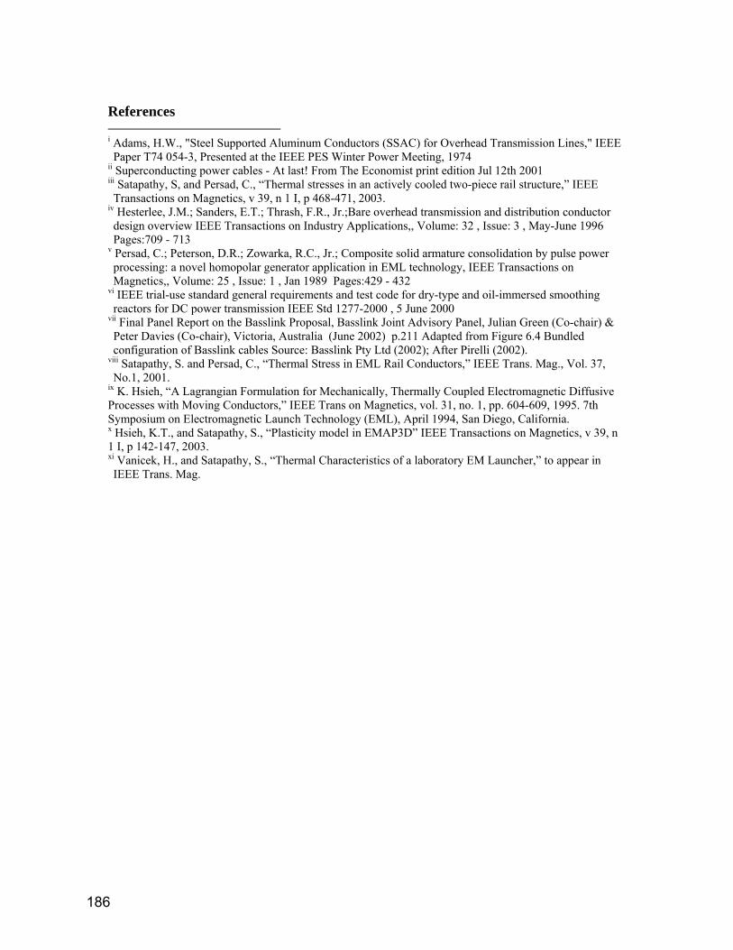
We also computed the grading effects in a tri-layer system. The resistivity ratios of the layers were independently set. Figure-10 shows the heat generation, and Figure-11 shows the temperature at four different points. It is clear that these fields are not a monotonic function of resistivity, i.e., a non-monotonic case results in lower heat generation and lower peak temperature. This fact bolsters the assertion that non-monotonic grading will help further reduce peak temperature and the thermal gradient.
Figure-10: Heat generated in a tri-layer system, shown on right.
293
393
493
593
693
793
893
0 1 2 3 4 5 6 7 8 9
Inner to Outer Resistivity Ratio
Tem
pera
ture
at F
our L
ocat
ions
(K
)
Mid-PtInner-CnrInterfaceOuter-Cnr
Figure-9: EMAP3D results for temperature variation.
184
Summary We used numerical tools to analyze the thermal performance of conductors exposed to pulsed current induced electromagnetic load. The resistivity of the conductor was varied spatially. We found that the peak temperature and the thermal gradient can be significantly reduced by grading the resistivity of the conductor material. We further found that the peak temperature location can be pushed away from the surface towards cooling channel locations to maximize cooling efficiency. Even though we have primarily conducted monotonic variations, we have demonstrated by one non-monotonic example that the optimal solution may involve non-monotonic property grading. From a manufacturing point of view, most of the conventional material grading techniques results in monotonic grading of material and properties. However, SFF holds the promise to achieve a non-monotonic grading to obtain optimal conductor characteristics. For such an embodiment, SFF offers a unique way to build an arbitrarily graded conductor using the described “materials-by-design” approach.
(a) Inner Corner (b) Outer corner
(c) Interface-1 (d) Interface-2
Figure-11: Temperature variation with resistivity ratios. The locations are
described in Figure 10.
185
References i Adams, H.W., "Steel Supported Aluminum Conductors (SSAC) for Overhead Transmission Lines," IEEE Paper T74 054-3, Presented at the IEEE PES Winter Power Meeting, 1974
ii Superconducting power cables - At last! From The Economist print edition Jul 12th 2001 iii Satapathy, S, and Persad, C., “Thermal stresses in an actively cooled two-piece rail structure,” IEEE Transactions on Magnetics, v 39, n 1 I, p 468-471, 2003.
iv Hesterlee, J.M.; Sanders, E.T.; Thrash, F.R., Jr.;Bare overhead transmission and distribution conductor design overview IEEE Transactions on Industry Applications,, Volume: 32 , Issue: 3 , May-June 1996 Pages:709 - 713
v Persad, C.; Peterson, D.R.; Zowarka, R.C., Jr.; Composite solid armature consolidation by pulse power processing: a novel homopolar generator application in EML technology, IEEE Transactions on Magnetics,, Volume: 25 , Issue: 1 , Jan 1989 Pages:429 - 432
vi IEEE trial-use standard general requirements and test code for dry-type and oil-immersed smoothing reactors for DC power transmission IEEE Std 1277-2000 , 5 June 2000
vii Final Panel Report on the Basslink Proposal, Basslink Joint Advisory Panel, Julian Green (Co-chair) & Peter Davies (Co-chair), Victoria, Australia (June 2002) p.211 Adapted from Figure 6.4 Bundled configuration of Basslink cables Source: Basslink Pty Ltd (2002); After Pirelli (2002).
viii Satapathy, S. and Persad, C., “Thermal Stress in EML Rail Conductors,” IEEE Trans. Mag., Vol. 37, No.1, 2001.
ix K. Hsieh, “A Lagrangian Formulation for Mechanically, Thermally Coupled Electromagnetic Diffusive Processes with Moving Conductors,” IEEE Trans on Magnetics, vol. 31, no. 1, pp. 604-609, 1995. 7th Symposium on Electromagnetic Launch Technology (EML), April 1994, San Diego, California. x Hsieh, K.T., and Satapathy, S., “Plasticity model in EMAP3D” IEEE Transactions on Magnetics, v 39, n 1 I, p 142-147, 2003. xi Vanicek, H., and Satapathy, S., “Thermal Characteristics of a laboratory EM Launcher,” to appear in IEEE Trans. Mag.
186