Embed Size (px)
Citation preview
American Institute of Aeronautics and Astronautics
1
Materials Combustion Testing and Combustion Product
Sensor Evaluations in FY12
Marit E. Meyer
NASA John H. Glenn Research Center
Cleveland, OH 44135
Paul D. Mudgett
NASA Johnson Space Flight Center
Houston, TX
Steven D. Hornung and Mark B. McClure
NASA White Sands Test Facility
Las Cruces, NM
Jeffrey S. Pilgrim
Vista Photonics, Inc.
Santa Fe, NM
Victoria Bryg
National Center for Space Exploration Research
Cleveland, OH 44135
Darby Makel
Makel Engineering
Chico, CA 95973
Gary A. Ruff and Gary Hunter
NASA John H. Glenn Research Center
Cleveland, OH 44135
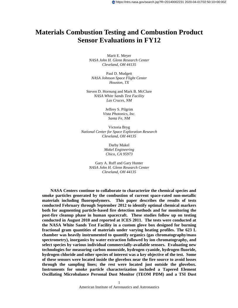
NASA Centers continue to collaborate to characterize the chemical species and
smoke particles generated by the combustion of current space-rated non-metallic
materials including fluoropolymers. This paper describes the results of tests
conducted February through September 2012 to identify optimal chemical markers
both for augmenting particle-based fire detection methods and for monitoring the
post-fire cleanup phase in human spacecraft. These studies follow up on testing
conducted in August 2010 and reported at ICES 2011. The tests were conducted at
the NASA White Sands Test Facility in a custom glove box designed for burning
fractional gram quantities of materials under varying heating profiles. The 623 L
chamber was heavily instrumented to quantify organics (gas chromatography/mass
spectrometry), inorganics by water extraction followed by ion chromatography, and
select species by various individual commercially-available sensors. Evaluating new
technologies for measuring carbon monoxide, hydrogen cyanide, hydrogen fluoride,
hydrogen chloride and other species of interest was a key objective of the test. Some
of these sensors were located inside the glovebox near the fire source to avoid losses
through the sampling lines; the rest were located just outside the glovebox.
Instruments for smoke particle characterization included a Tapered Element
Oscillating Microbalance Personal Dust Monitor (TEOM PDM) and a TSI Dust
https://ntrs.nasa.gov/search.jsp?R=20140002231 2020-04-01T02:50:10+00:00Z

American Institute of Aeronautics and Astronautics
2
Trak DRX to measure particle mass concentration, a TSI PTrak for number
concentration and a thermal precipitator for collection of particles for microscopic
analysis. Materials studied included Nomex®, M22759 wire insulation, granulated
circuit board, polyvinyl chloride (PVC), Polytetrafluoroethylene (PTFE), Kapton®,
and mixtures of PTFE and Kapton®. Furnace temperatures ranged from 340
o to
640o C, focusing on the smoldering regime. Of particular interest in these tests was
confirming burn repeatability and production of acid gases with different fuel
mixture compositions, as well as the dependence of aerosol concentrations on
temperature.
I. Introduction
ASA’s ongoing collaborative efforts to develop early fire detectors and post-fire cleanup equipment include
characterizing the smoke generated by common spacecraft materials. Understanding the most likely gas and
aerosol fire signatures on a spacecraft is fundamental to the design of a fire protection system. Initial testing at
WSTF in 2010 focused on developing a consistent post-fire challenge for the purpose of requirements definition and
qualification of post-fire cleanup protective breathing equipment [1]. Subsequent testing in 2011 added instruments
to characterize the smoke aerosol particles as well. Further work took place in 2012 with two additional test
campaigns at the NASA White Sands Test Facility (WSTF). Multiple entities participated, bringing newly
developed and mature gas sensors and aerosol instruments. These latest testing activities have benefitted from
improvements to the test facility itself. Test matrices were broadened with the investigation of new fuels and
various fuel preparation methods.
II. Test Facility and Procedures
The test facility consists of an exposure chamber, a custom smoke generator, and reference instruments. Several
types of fuel samples have been developed and used in this test program as well as specialized test procedures.
These are discussed in the following sections as well as the diagnostics specifically included for this test program.
A. Exposure Chamber and Smoke Generator
An instrumented chamber was developed for this testing. The chamber, shown in Figure 1 has a volume of 623 L
(22 ft3) with support plumbing to exhaust the chamber to a roof vent stack, as well as two fans to circulate the
chamber atmosphere. The circulation fans are controlled through the data system and used during each test. Tests
were conducted in ambient air at 12.4 psia (WSTF ambient atmospheric pressure). The chamber has ports for
withdrawing samples and accommodating power and data cables. Figure 2 is a schematic representation of the
instrumentation used in the testing.
The smoke generator,also shown in Figure 1, consists of a quartz-lined electrical tube heater with an air supply
line that introduces a low flow of air to the hot mixture. This system has been designed so that both flaming and
smoldering fires can be simulated. Several different smoldering conditions, which typically have the highest
production rate of toxic products, were run in this test by operating the tube heater at specific set-point temperatures
between 350 to 640 oC. In general, these scenarios emulate 1) a low temperature fire that produces a maximum of
volatile organic compounds with little thermal oxidation, 2) a higher temperature test where the conditions produce a
significant concentration of carbon monoxide (CO), and 3) a condition that produces the worst-case particulate
concentration. Flaming conditions are simulated as a variant of the high temperature smoldering challenge where the
effluent is intentionally ignited remotely after smoke production is well established. Furnace temperature control
was improved for the current testing by adding a feedback temperature controller with a user selectable heating rate.
Additional ports were added to improve chamber access and accommodate additional external sensors.
B. Sample Materials and Conditions
The experimental design has “evolved” somewhat with each test as we learn how to conduct this type of testing
in an efficient way. Each test campaign was limited to 1 week, which forced us to be economical in choosing the
fuels, parameters and replicates. The week-long tests carried out in 2012 differed from the original test in August
2010 and from each other in several ways. Based on the 2010 results, the fuel mass was standardized at 0.5 g per
burn. A somewhat different set of fuel materials was used in each test, but with significant overlap. For the
N

American Institute of Aeronautics and Astronautics
3
September 2012 test, to enable complete burns, we decided not to pelletize the fuel; rather, loose granulated material
was placed carefully on the mica liner and inserted into the oven.
Figure 1. Exposure chamber during September 2012 testing (left), Smoke generator (right).
Figure 2. Schematic of instruments placed inside and plumbed to the chamber, including laminar flow
elements (LFE) for dilution of aerosol instruments.
Tables 1 and 2 show the test matrices from the two test campaigns in 2012. Differences in the temperatures,
materials, number of replicates and total number of runs indicate the evolution of the WSTF testing efforts and
emphases. The Standard Mix fuel is a mixture of twelve granulated constituents represented in specific mass
fractions down to the hundredth of a gram. Exact proportions and materials are outlined in Reference 2. This
material was created as a fire fuel proportionally representative of materials on spacecraft. This fuel was
predominantly used in February/March testing and in previous WSTF test campaigns [2]. Materials used for the
February/March test are shown in Table 1. The PFPI wire insulation is partially fluorinated polyimide manufactured
by TRW. The circuit board was a downgraded flight spare fully populated with certified conformal coating as an
example of modern electronics. Materials for the September testing are shown in Figure 3. For the Sep 2012 test,
we researched the current spacecraft wire specification and found it to be Mil Spec M22759, produced by using a
QCL CO Spectrometer
Portable SSFD
Thermal Precipitator
DustTrak II
Aerosol InstrumentsGC/MS Sampling
Wet Trapping
HCN PAS
TEOM PDMLFE-3
Filter
AmbientAir
LFE-2
FilterAmbient
Air
Filter Pump
(internal pump & filter)
CSA-CP Fixed SSFD
Drager Pac III – CO, HF/HCl, HCN, NO2
HFIII, HCPM
COMA
DragerXam 5600
P-Trak8525
LFE-4
Filter
AmbientAir
Exposure ChamberSensors Inside Chamber
Gaseous Product Instruments
Outside Chamber
(internal pump & filter)
(internal pump & filter)
LFE-1
Filter(internal pump & filter)
DustTrakDRX
AmbientAir

American Institute of Aeronautics and Astronautics
4
PTFE and polyimide tape wrap process to produce layers over the conductor which are then thermally fused. The
insulation was stripped from 12 gauge M22759/86 wire (manufactured by Nexans) in short random lengths, and
used as-is without further granulation. The Nomex cloth was scissors cut into 3 to 5 mm shredded pieces. PTFE
granules were made with a rotary shaving device, whereas the PTFE powder was purchased, with a uniform size of
100 μm. The Kapton pieces were thin strips of film cut into approximately 2 mm squares. The Kapton film was
difficult to shred and required some hand sorting to eliminate larger pieces. The granulated circuit board was made
with a rotary grinder and metal portions of the circuit card assembly were avoided during the grinding process and in
weighing out the 0.5 gram samples to avoid skewing the weight of the 0.5 g sample.
Table 1. Feb-Mar 2012 Test Outline (some ignition) Material (0.5 g) Furnace Temp/C Ignite Replicates # Tests Notes
Standard Mix 340,440,540,640 Yes 1-2 7 Granulated, see Reference 2
Granulated Circuit Board 340,440,540 Yes 2-3 5 Populated, conformal coated
PFPI wire insulation 540,640 No 3-4 7 20AWG stripped
100% PTFE 540,640 No 2-3 5 Granulated
100% Kapton 540,640 No 2-3 5 Granulated
50:50 PTFE/Kapton mix 540,640 No 1-2 3 Mixtures of above
25:75 PTFE/Kapton mix 540,640 No 2 4
75:25 PTFE/Kapton mix 540,640 No 1-2 3
10:90 PTFE/Kapton mix 640 No 2 2
90:10 PTFE/Kapton mix 640 No 2 2
Total Runs: 43
Table 2. Sep 2012 Test Outline (No ignition) Material (0.5g) Furnace Temp/C Replicates # Tests Notes
Nomex 640 7 7 HT9040, natural, untreated
Nexans Wire Insulation 640 6 6 M22759/86 12AWG stripped
100% PTFE 640 8 8 4 Granulated & 4 powdered PTFE
100% Kapton 640 5 5 Granulated
PTFE/Kapton mixes 640 3-4 18 10/90; 90/10; 25/75; 75/25;50/50
Circuit Board (PCB) 340,440,540,640 2 8 Granulated
PVC 640 1 1 Granulated; for HCl production
PCB+PVC 640 3 3 0.5g PCB with 0.05g PVC “std addition”
PCB+PVC 640 2 2 0.5g PCB + 0.1g PVC
PTFE+PVC 640 1 1 0.4g PTFE + 0.1g PVC
Total Runs: 62
Figure 3. September sample materials before burning.

American Institute of Aeronautics and Astronautics
5
C. Test Procedure
The sample tube heater near the center of the chamber is controlled by a LabView interface which dictates the
temperature ramp duration and magnitude. The test procedure timing is outlined in Table 3. A fan near the rear
corner is turned on for approximately 30 seconds after the heater is turned off to provide a uniform concentration
inside the test chamber. After mixing, the combustion products are allowed to decay for 5-10 minutes after which
the chamber is purged with a vent fan. The front ports are opened to allow fresh lab air to be pulled into the
chamber during venting. The time to complete a test, from the chamber sealing until the final venting is
approximately 20-30 minutes.
Table 3. Standardized Test Procedure Timing (each run)
Step Description
1 Load fuel, close up chamber, turn off purge vent
2 Ramp furnace temperature up to target temperature
3 Turn furnace blower ON once furnace temperature reached (at t=3 min)
4 Hold furnace temperature for ~ 4min
5 Turn off furnace at t=7 min & stir chamber via muffin fan for 30 sec
6 5 to 10 min dwell/natural decay (occasionally longer)
7 Vent chamber, switch on purge duct fan
8 Remove and weigh ash
III. Test Instrumentation
A record number of sensors were incorporated in the testing campaigns of 2012. Table 4 lists each instrument
and identifies its core technology. The source of each instrument is either the designer or manufacturer and the
sponsoring NASA organization that facilitated participation in the WSTF testing. Not all instruments were present
both in February/March and September testing and improvements were made to some in between testing campaigns.
Table 4. Test Instrumentation
Instrument Source Core Technology Target Analytes
PAS Vista Photonics/GRC Photoacoustic TDLS* HCN
HFIII, HCPM Vista Photonics/GRC&JSC Enhanced TDLS HF, HCl
COMA Vista Photonics/GRC Multipass TDLS CO with CH4 compensation
SSFD Fixed unit Makel Engineering/GRC Solid state sensor CO, CO2, hydrocarbons (HC)
SSFD Portable unit Makel Engineering/GRC Solid state sensor CO, CO2, hydrocarbons (HC)
CSA-CP Industrial Scientific/JSC Electrochemical cell O2, CO, HCN, HCl
Xam-5600 Draeger/JSC Electrochemical cell/NDIR O2, CO, HCN, CO2
PacIII Draeger/WSTF Electrochemical cell CO, HF/HCl, HCN, NO2
Thermal Precipitator GRC Particle thermophoresis Aerosol capture for microscopy
TEOM PDM ThermoFischer/GRC Gravimetric Aerosol mass concentration
DustTrak DRX TSI, Inc./GRC Laser photometer, with single
particle counting
Aerosol mass concentration
DustTrak II TSI, Inc./WSTF Laser photometer Aerosol mass concentration
P-Trak 8525 TSI, Inc./WSTF Condensation/Light Scattering Ultrafine particle concentration
GC/MS** Hewlett Packard/WSTF Gas chromatography/mass
spectrometry
Volatile organic compounds
Ion Chromatography WSTF Offline IC, wet trap sample
analysis
Inorganic anions
Quantum Cascade
Laser Spectrometer***
Port City Instruments/JPL Multipass TDLS CO
*Tunable diode laser spectroscopy **GC/MS data not included ***This spectrometer is not described here
A. Tunable Diode Laser Spectroscopy based instruments from Vista Photonics
An improved photo-acoustic (PAS) based HCN sensor was present at both rounds of WSTF testing in 2012. This
sensor is superior to the earlier FY2010 PAS instrument which operated at 1531 nm [3]. That sensor read

American Institute of Aeronautics and Astronautics
6
significantly higher HCN levels than other available diagnostics under the test conditions. It appeared that other, as
yet unknown, combustion evolved hydrocarbon species were contributing to the HCN measurement. In contrast, the
new PAS sensor operates at 2498 nm where fewer hydrocarbons can interfere with HCN measurement. The PAS
gas sensor cell was thermoelectrically heated to a fixed temperature in order to maintain a stable acoustic resonance
frequency. The laser diode was simultaneously wavelength modulated and wavelength scanned by injection current
over the line center of the gas target absorption feature. The laser wavelength was modulated at the 3 kHz cell
resonance frequency. Absorption of laser emission by the target gas is converted to sound occurring at the
modulation frequency, which is the natural resonance frequency of the acoustic cell. The cell resonance provides
about an order-of-magnitude improvement in sensitivity over non-resonant operation. Measurement precision for
HCN is about 0.3 part-per-million (ppm) with a linear averaging time of 20 seconds. Present testing has shown a
much closer correlation with other HCN sensors, indicating that this new wavelength is unaffected by other
combustion products.
Earlier PAS combustion measurements at WSTF have shown that optical approaches suffering long sample
interaction times are not effective when applied to highly reactive transient evolved combustion species. In contrast,
the present employed technique for reactive acid gases utilizes rapid sampling and short sample interaction paths in
an SBIR-developed proprietary path length enhanced optical approach combined with wavelength modulation
spectroscopy (WMS) and tunable infrared semiconductor laser diodes [4]. Several prototypes have been successfully
demonstrated for monitoring hydrogen fluoride (HF) in testing at WSTF using distributed feedback (DFB) laser
diodes. A companion effort recently demonstrated that like performance for hydrogen chloride (HCL) can be
provided using a similar architecture. Two recent developments have enabled a multi-gas optical acid gas monitor
with increased performance. 1) Demonstration of sub-parts-per-million (ppm) sensitivity for HCL at 1742 nm allows
implementation in a common sample cell with the HF sensor operating at 1312 nm and using the same electronics.
2) The emergence of vertical cavity surface emitting laser (VCSEL) diodes at both wavelengths eliminates the need
for fiber-coupled telecom devices which draw much more power and reduce portability. The new prototype device
employed in the present WSTF testing combines VCSEL-based, real-time, high-performance concentration
measurements with rapid sampling for both HF and HCL simultaneously. Little surface interaction is suffered as the
gas samples need only traverse a few mm aperture to enter the optical cell and are directed across the aperture by a
simple fan. A second Phase III-developed HF sensor, utilizing a fiber coupled DFB laser diode at 1312 nm, was also
employed in the present testing. HF measurement precision is better than 0.1 ppm and HCL is better than 0.2 ppm.
A VCSEL-WMS sensor for CO utilizing a simple optical multipass cell was designed and built on a Phase II
SBIR project (CO multipass analyzer, COMA). The delivered sensor version operates with a netbook computer
(Mini 9, Dell). Although the sensor has already been operated with Field-Programmable Gate Array (FPGA)
electronics during the Phase II project, the netbook based version is more flexible and allows easy change of sensor
parameters. The netbook based version is more suited for WSTF testing due to its adaptability in the field. The
sensor dimensions are 17.8 cm x 12.7 cm x 8.1 cm (not including the netbook). An FPGA based (stand-alone) CO
sensor has similar dimensions. Note that the aim of the electronics development is to operate the CO sensor as an
additional channel of an emerging Vista Photonics combined combustion products monitor (CPM). The sensor cell
is designed for compactness and ruggedness. It has no moving parts; all components are solidly mounted. Cell
dimensions are about business card size . In the developed sensor cell the laser is solidly attached to the cell at an
angle. This angle is precisely machined into the cell. It determines the number of passes through the cell. Eight
passes are realized in this cell leading to an absorption path-length of 63.6 cm. Measurements at WSTF were
performed with a low-power, non-temperature stabilized sensor. Free-space single mode 2330 nm VCSELs are
utilized in the COMA architecture. The VCSELs typically deliver about 0.3 mW of output power in single mode
operation and are tunable from about 2333 nm to 2341 nm. CO measurement precision is about 0.5 ppm.
B. Fixed and Portable Smart Space Fire Detection System (SSFD)
Fixed and portable version of a Smart Space Fire Detection System (SSFD) developed by Makel Engineering,
Inc. and NASA GRC were tested. Intial versions of these systems were tested in 2011 [5]. The SSFDS
includes the core electronics, interfaces, microprocessor, and overall hardware architecture from the “Lick and
Stick” technology developed for space flight leak detection applications and a fire detection system developed for
aeronautics [5-6] .

American Institute of Aeronautics and Astronautics
7
The current generation of the SSFD sensor system provides the capability to detect CO, CO2, O2, H2, and
hydrocarbons while tracking temperature, pressure, and humidity. The individual solid state sensors are integrated
into a single package that is approximately 17.8 cm wide x 10.2 cm long x 4.6 cm tall, excluding the external
cable, with weight and power consumption near a 1 kg and 6 W respectively. There is an electrical connector for
power and RS485 communication, but the system can be configured for wireless capability. The portable version of
the device includes a touch screen LCD, sampling pump, and rechargeable battery. For the fixed system the sensor
elements are exposed to the external environment by diffusion through stainless steel filters standardly used in
combustion product monitoring, but are sealed internally from the rest of the electronics and enclosure. For the
portable SSFD, a sample pump inside the unit pulls air to the enabling the system to used as a sniffer.
The overall design of the unit enables the device to incorporate new sensor types and improved sensors for
individual species with minimal rework of the unit. The modular electronics also enables upgrade and improvement
to the hardware. The MEMS chemical sensor technology used in the both systms consists three different types of
MEMS chemical sensor platforms resistors, so l id s ta te electrochemical cells, and Schottky diodes. Each sensor
type or platform provides very different types of information on the environment and is meant to have limited
cross-sensitivity (i.e., be orthogonal in its response). Integration of the information from these orthogonal sensors
can provide increased whole-field information on the environment. The approach is to give quantitative readings of
the species of interest. The current generation of the systems tested included specific improvements to CO and CO2
sensor sensitivity and stability. In addition, refined real-time algorithms for improving individual sensor selectivity
were implemented. Thus, this testing employed the same core sensor technology, but integrated with different
hardware platforms and implemented at different locations in the test environment. The data presented in this paper
will concentrate on the results provided by two types of CO sensors in both a fixed position unit and a portable unit.
One sensor is intended for low concentration measurements (Fixed-L and Portable-L) and is intended to also have
use in environmental monitoring. The second type of CO sensor is intended have a broad range of detection
capabilities extending into higher levels of CO concentration that may be present in some fire conditions (Fixed-H
and Portable-H). Data from the other sensor technologies was also recorded and is available for future analysis and
crosscorrelation.
C. Compound Specific Analyzer-Combustion Products (CSA-CP), Draeger X-am 5600, Drager Pac III
Several commercial multi-gas monitors were used in the test, including the Compound Specific Analyzer-
Combustion Products (CSA-CP) from Industrial Scientific which is identical to that used on the International Space
Station, and an X-am 5600 unit from Draeger. Both measure O2, CO, and HCN electrochemically. Additionally,
the CSA-CP measures HCl electrochemically and the X-am 5600 measures CO2 by infrared detector. Both units
were calibrated at Johnson Space Center in Houston prior to the test and checked at WSTF before and after the
testing. The units were located front and center inside the chamber (see Figure 1) to be able to see the display and
record the maximum concentrations during each test. Data were also automatically logged and downloaded after all
testing was completed. The Draeger PacIIIs are single gas electrochemical monitors equipped with sensors for CO,
HCN, and HF/HCL. These three units were also located near the front ports. Prior to testing these monitors where
calibrated using commercial certified gas standards.
D. Aerosol Thermal Precipitator
A thermal precipitator was designed at Glenn Research Center to collect smoke aerosol particles for microscopic
analysis. The design takes advantage of the thermophoretic force on a particle in a large temperature gradient
created by opposing thermoelectric coolers and kapton heaters. The particles are driven to the cold side of the
gradient, which in this device is set of SEM stubs prepared with a section of carbon tape and TEM grids to facilitate
a variety of analyses. Information on particle morphology, size, chemical composition and agglomerate structure
obtained from these tests supplements aerosol concentration data collected.
E. Tapered Element Oscillating Microbalance (TEOM) Personal Dust Monitor (PDM)
The TEOM is a direct-reading gravimetric aerosol instrument manufactured by Thermo Fisher Scientific that
measures aerosol mass deposited on a filter. The filter is mounted on a hollow tapered glass stalk through which air
is drawn and which vibrates at a frequency proportional to the mass on the filter. The system electronics monitor the
frequency changes, and changes in mass on the order of micrograms are computed and recorded every 5 seconds.
Aerosol mass concentration can be derived from the change in mass on the filter and the known volumetric flow rate
of air through the filter. The PDM is a wearable respirable dust sampling version of the TEOM for use in mining
and other hazardous occupations.

American Institute of Aeronautics and Astronautics
8
F. DustTrak DRX Monitor and DustTrak II
Aerosol photometers measure mass concentration by measuring the combined laser light scattered from many
particles at once. Both DustTrak ™ monitors (TSI Inc.) are the same except the DRX combines ensemble
scattering with single particle detection to provide real-time size-segregated mass fraction concentrations up to 150
mg/m3. In this testing, aerosols below 1 μm in diameter are the predominant sizes however it is of interest in fire
characterization to determine which fuels generate particles above this threshold. Optical aerosol instruments give a
material-dependent response, with particle refractive index dictating the amount of light scattered. This instrument is
factory calibrated with Arizona Road Dust for the wider market of occupational hygiene applications. A custom
calibration for smoke was performed using a polydisperse mineral oil aerosol that resembles the size distribution of
smoke.
G. P-Trak 8525
The P-Trak™ (TSI Inc.) is a condensation particle counter that measures aerosol number concentration. This
device operates by passing the aerosol-laden particle stream through a region saturated with isopropanol vapor and
then into a cooler region where the vapor condenses onto the particles increasing their diameter such that they can be
readily counted by a light scattering device. This instrument is designed for the occupational hygiene market and
operates over a range of 0 to 105 particles/cm
3 and 20 nm to 1 μm diameter. Dilution is required, since the smoke
concentration is higher than the upper range limit.
H. GC/MS
A Hewlett-Packard1
5890A Gas Chromatograph with a 5970 Series Mass Selective Detector was assembled to
perform analyses of combustion products. The Gas Chromatography with Mass Spectral Detection (GC/MS)
instrument was equipped with a 30-m x 0.53-mm ID x 5-µm phase 100-percent dimethyl polysiloxane capillary
column, a VICI2
direct injecting 10-mL sampling loop, and a 6-port valve. To obtain a sample, a 12-ft heated
transfer line, transfer line isolation valve, vacuum pump, and vacuum pump isolation valve were used to move the
gas sample from the mask to the sampling loop. The inlet system is configured so that the vacuum pump evacuates
the valve, loop, and heated transfer line to the transfer line isolation valve. The vacuum pump isolation valve is then
closed and the heated transfer line isolation valve opened to pull in the gas sample to be analyzed. After the gas
sample is pulled into the loop, the pressure is measured, the 6-port valve switched, and the gas sample injected onto
the column.
I. Ion Chromatography
The wet-trap samples were acquired by pulling an air sample from the chamber over a sorbent wetted with
deionized water at a measured air flow rate for a specific time. This sorbent was then desorbed into 10 mL of IC
eluent, filtered then run on the ion chromatograph (IC). Chamber concentration of acid gas was calculated by flow
rate, time, volume of water in the trap and concentration of the corresponding anion determined by the IC.
IV. Results and Discussion
With the exception of the GC/MS data, all of the results from the two testing campaigns are tabulated in the
appendices. While all individual chemical parameters could be plotted and commented on, only select data are
analyzed, plotted and discussed as examples or highlights for brevity. Photographs of the residual ash after testing
are shown in Figure 4 and masses are given in Appendix E.
The goal of the testing, along with proving instrument performance, is to consider spacecraft fire characteristics,
including gas and aerosol signatures. Many topics concerning the data merit their own dedicated study, however,
some of the chemical and aerosol results are discussed here in light of ongoing WSTF testing and the sensors under
development.
A. Particle Microscopy
As part of the particle characterization of smoke aerosols generated during two White Sands testing regimens,
samples were collected via a thermal precipitator. The thermal gradient allows particles to collect on scanning
electron microscopy (SEM) stubs and transmission electron microscopy (TEM) grids. A strip of conductive carbon
1 Hewlett-Packard
is a registered trademark of Hewlett-Packard Development Company, Houston, TX.
2 VICI
is a registered trademark of Valco Instruments Company, Inc., Houston, TX.

American Institute of Aeronautics and Astronautics
9
film was placed onto the surface of the SEM stub to allow for viewing of the particles on both the aluminum stub
substrate as well as a neutral carbon background. TEM grids with a) contiguous carbon film as well as a b) holey
carbon film were placed at the edge of the carbon film to allow sample collection for higher magnification
examination. Observations about aerosol particle size and morphology are made with a Hitachi SEM and Philips
TEM. Elemental information is gained by use of an EDAX energy dispersive x-ray analyzer (EDS) instrument on
the SEM. The images shown here are typical of those generated by the heated samples.
Figure 4. September sample ash after burning, arranged in chronological order of tests.
A 100% Teflon sample burned at 640 oC during February testing is shown in Figure 5. Teflon particles are
generally spherical. Other areas on the 640 oC sample SEM stub (not pictured here) show evidence of acid pitting
(potentially from HF), as well as the precipitated particles. The image on the left is a SEM image of precipitated
particles and the center image is an elemental map showing fluorine (F) within the particles. It is interesting to note
that the fluorine is still concentrated in the aerosol particles which indicates that the material did not decompose
significantly during the test. Another indication that the Teflon is still intact is shown in the TEM image on the right
where the Teflon particle exhibits a crystalline interior with an amorphous coating.
Figure 5. Teflon sample at 640
o C on SEM stub with map showing concentration of fluorine (center) and
HRTEM image (right).
Figure 6 illustrates particles from the September tests. This is a sample of a circuit board at 640oC. Circuit boards
exhibit significant amounts of particle deposition. Elements detected within these particles include oxygen, copper,
iron, silicon, and fluorine; a representative EDS spectra from this sample is shown on the right. The gold in the EDS
spectra is from a coating sputtered onto the stub to prevent charging.

American Institute of Aeronautics and Astronautics
10
Figure 6. Circuit board sample at 640
o C with map showing concentration of oxygen (center) and a typical
EDS spectra (right).
Nomex particles were mostly spherical. EDS results indicate that Nomex aerosol particles contained bismuth,
which is a heavy metal additive that increases flame retardancy and inhibits smoke generation. Particles captured
from other sample materials were all mostly spherical with the exception of the Kapton, which exhibited string-like
agglomerate structures. Figure 7 shows representative images of the wire insulation, Kapton and Teflon, all at 640o
C. The thermal precipitator was not designed to capture particles for the purpose of generating a particle size
distribution by microscopy. The design intent was to give insight into particle morphology and smoke repeatability,
and there may be some size fractions that were not captured at all due to the limitations of the thermophoretic
sampling process, fixed flow rate and other design parameters.
Figure 7. Wire insulation particles at 640
o C are nearly spherical (left), some Kapton particles at 640
o C
exhibit chain-like agglomerate structure (center), a 640o C Teflon particle which is a compact agglomerate
made up of nanoparticle primaries. The rod to which the particle adhered is the carbon film of the TEM
grid.
B. Chemical Combustion Products: Select Results and Trends
A significant amount of data across multiple chemical sensor systems was collected during this testing. The
Appendices briefly summarize the large amounts of raw data associated with various test runs. In general, there was
notable consistency amongst the various sensor outputs although some variation was noted. Analysis of this data,
evaluation of sensor system performance, and reasons for potential variations in sensor response is beyond the scope
of this paper, and an appropriate subject for a separate paper. The purpose of this section is to give general trends
and summarize some of the highlights of the data observed this testing.
Much of the chemical data (peak concentrations from all sensors for each run) from the September 2012 test
(640o C without ignition) is reduced and displayed in Fig 8 as averages and ranges, although the PFPI wire
insulation and Standard Mix data are from the Feb test. Figure 8 serves as a quick comparison chart and reference
for gas production vs. material and is helpful in designing combustion experiments and sensor evaluations in a
“relevant environment”. The CO concentration range for Kapton was the widest for a single material, and PTFE the
smallest. CO yield for PTFE was also smallest (9 ppm average). Mixtures (PTFE/Kapton indicated as mass
percentages) gave interesting results. A small amount of Kapton added to PTFE dramatically increased CO and vice
versa. Yield for M22759 wire insulation is similar in CO production to 90/10 PTFE/Kapton, whereas the PFPI wire
insulation approaches that of 75/25 PTFE/Kapton. As expected the PTFE and PTFE containing fuels produce the
0
100
200
300
400
500
600
700
800
900
1000
16
11
21
18
12
41
30
13
61
42
14
81
54
16
01
66
17
21
78
18
41
90
19
61
10
21
10
81
11
41
12
01
12
61
EDS Spectra Circuit Board 640o C (Au coated on carbon film)
Au
Cu
O
Al
O map#33 –Circuit board –640oC
Counts
0.2mm
0.5mm
0.1mm
20 nm
250 nm

American Institute of Aeronautics and Astronautics
11
highest HF concentrations whereas materials like Nomex, containing no fluorine naturally do not produce HF. The
PCB and Standard Mix produce little HF. The 2 different types of wire insulation gave similar average HF
production with differing ranges. A small amount of Kapton in Teflon mixture appears to boost production of HF.
Future work should include a study of the role of proton donor in HF production. As expected, Kapton is best
producer of HCN and PTFE least (zero). Interestingly, a small amount of PTFE in Kapton seems to boost HCN
production. The 4 ppm average HCN from M22759 wire insulation reflects the tape wrap style construction—a thin
layer of polyimide between 2 layers of PTFE. PFPI wire insulation produces little HCN, although the backbone is
polyimide. That observation along with the high HF signature indicates that “partially fluorinated” is actually a
large degree of fluorination.
The September test was the first to detect HCL unequivocally from PVC and PVC-containing mixtures via
TDLS. Presence of significant acid gases were confirmed via the wet trap ion chromatography results (see
Appendix B & D). As an example, Fig 9 shows that acid gases persist in the chamber longer than expected—there
is a spike in production then an initial rapid decay, in which HF/HCl are reacting with surfaces in the chamber, then
a slow decay, with these toxic species persisting for 10’s of minutes. It appears the surfaces become less
accommodating for the acid gases during prolonged exposure. Note that the HF concentration never returns to zero
between runs after the chamber has been exposed a few times. Run 13 (Fig 9 right) was allowed to run for an
extended period, and results show HF still present after more than two hours. An exponential model would predict
nearly complete decay of HF within about 20 minutes based on the initial, rapid, decay. Nonetheless, after 20
minutes the HF concentration is about four times higher than predicted by an exponential fit. This has implications
for fire response on spacecraft and other closed inhabited environments and for combustion product monitor
development.
Figure 8. Range and Average of Maximum Concentration of Gas Products vs. Fuel Material at 640o C.
Nomex M22759 PCB PTFE Kapton 10/90 25/75 50/50 75/25 90/10 PVC PFPI* Std Mix*
0
5
10
15
20
25
30
35
40
45
50
0
50
100
150
200
250
300
350
400
450
500
0
Co
nce
ntratio
n o
f HF an
d H
CN
(pp
m)
Co
nce
ntr
atio
n o
f CO
(pp
m)
CO
HF
HCN

American Institute of Aeronautics and Astronautics
12
Figure 9. Production and persistence of HF and HCL from PTFE/PVC burns (Runs 54-56, Left), each with a
short decay before venting the chamber, and HF from the burn of M22759 wire insulation (Run 13, Right)
which was intentionally left to decay for approximately 3 hours.
Figure 10. Comparison of CO sensor performance for Kapton at 2 burn temperatures (February/March).
Different sensor technologies were compared in the tests with standard commercial units. Figure 10 illustrates
one such analysis-- the maximum CO values from all sensors in Kapton runs during the February/March test, which
showed remarkable precision with all sensors reporting CO within 10% of the mean for a given run. Results varied
between runs, but that was a function of other factors--studied in a little more depth in the September test. The Sept
2012 test sequence was our most recent and most well controlled, so it is the best data for which to discuss run-to-
run variability (reproducibility) for the current practice. The September data in Appendices C and D includes
calculated average and standard deviation. Based on the CO results, the run-to-run reproducibility within a given
material, with the exception of PTFE, ranged from 12.5 to 18% relative standard deviation (RSD). The M22759
wire insulation had the lowest RSD for CO at 12.5%, indicating best reproducibility as measured by all the CO
sensors. The RSD for PTFE was about double (29%), but that is likely from the fact that the CO yield is low for
PTFE (9 +/- 3 ppm). The run-to-run RSD for HCN from Nomex was about 20% and that for M22759 wire
insulation was 15.3%, which indicates decent reproducibility in terms of HCN, despite the lower yields. Because
30
25
20
15
10
5
0
pp
m
3:45 PM9/13/2012
4:00 PM 4:15 PM 4:30 PM 4:45 PM
date/time
HClHF
Run 54 Run 55 Run 56
14
12
10
8
6
4
2
0
HF
, p
pm
12:00 PM9/11/2012
12:30 PM 1:00 PM 1:30 PM 2:00 PM
date/time
Run 13
60
80
100
120
140
160
180
200
500 550 600 650 700
CO
co
nce
ntr
atio
n/p
pm
Temperature/C
CSA-CP
Draeger
COMA
Fixed-L
Fixed-H
Portable-L
Portable-H
Run 2. 1342
Run 1. 16116
Run 1. 1522
Run 2. 1267

American Institute of Aeronautics and Astronautics
13
the acid gas yield was generally also much less than CO (except for PTFE) and more reactive than CO and HCN, the
RSDs tend to be higher for HF and HCl, thus less useful for assessing run-to-run variation.
1) Fuel Preparation Effects
Testing in February/March involved mostly pelletized fuel. This was the approach taken for the early fire
cartridge testing process in 2010 and had persisted for subsequent campaigns. The standard mix had variation in
the textures of the constituent materials that the pellet provided a consistent starting configuration. Some materials
retained the pellet shape throughout the burn whereas other materials collapsed into granules, providing more
available surface area. When the pellet remains intact, the thermal decomposition mechanism may be altered by
the presence of a char front that progresses into the pellet over the duration of the test. Combustion products
generated at the char front must traverse the surrounding ash in order to be liberated. This process was never
rigorously investigated, however, in order to remove this variability between fuel materials, the second round of
testing was performed without the pellet press. Thus all the fuels had a larger surface area available for thermal
decomposition.
Less HF from Pelletized Fuel versus Powder
The pelletized blends of PTFE and Kapton produced significantly lower levels of HF than the loose mixtures as
determined by the identical HF optical sensor placed in the same relative proximity to the combustion source. While
the two rounds of testing occurred about 6 months apart for the pelletized samples and the loose samples, relatively
good agreement was obtained for wire insulation samples under the same test conditions (e.g. 640o C). Figure 11
presents the wire insulation samples average HF production over multiple replicates as a horizontal line. Although
different types of wire, note the good agreement from the two rounds of testing for the wire insulation regardless of
whether the sample was pelletized or loose. It stands to reason that the wire insulation is already well mixed due to
the nature of its construction and that pelletized or loose grouping of the insulation does not significantly impact
surface interaction effects which are those likely responsible for promoting HF production. Importantly, there is a
significant difference in HF promotion based on whether the blended samples are pelletized or loose. Indeed, the
pelletized blends, regardless of mixture fraction, never produce as much HF as the pelletized wire insulation. In
contrast, the higher PTFE fractions in the loose mix produce more HF than that produced by the loose wire
insulation. This is strong evidence for the importance of surface and localized gas phase interactions between the
PTFE and Kapton materials in producing HF. The wire insulation produces high levels of HF in both cases and
provides large surface interaction between the two materials. Likewise, the loose mixtures may produce more HF
because of the blurring of inside versus outside interactions produced by the pellet arrangement. The loose material
also likely heats up more uniformly over a greater surface area than the pelletized material. For larger PTFE
fractions the wet trap results (Fig 11) are significantly higher, perhaps indicating there are other fluorinated products
that hydrolyze and yield additional fluoride in the wet trap.
Figure 11. Concentration of HF as a function of PTFE fraction in sample material mixture, compared with
the horizontal lines which depict wire insulation samples’ average HF production over multiple replicates.
25
20
15
10
5
0
HF
(p
pm
)
1.00.80.60.40.20.0
PTFE fraction
pellet mixloose mixwet trap

American Institute of Aeronautics and Astronautics
14
Effect of Fuel Preparation on Smoke Aerosol
It was observed that the aerosol mass concentration was approximately equal for a 100% PTFE pellet in the
February/March testing and the loose ground PTFE test in September. This can be attributed to the nature of ground
PTFE, which does not hold its pellet shape very well in spite of 10,000 psi of the pellet press. Thus the pellet
process was never effective on that material. September testing showed the effect of the commercial 100 μm PTFE
powder which makes 1/3 more aerosol mass concentration than the ground PTFE. The ground PTFE had granules
that were much larger than 100 μm, as can be seen in the unburned fuel samples in Figure 3. The most significant
effect of fuel preparation on aerosol output was with Kapton, where it was seen that the granulated Kapton produced
five times more aerosol mass concentration than the Kapton film squares, which can be attributed to more surface
area in granulated Kapton. The wire insulation was changed between the two test campaigns, and the average
aerosol mass concentration in February/March was 0.013 g/m3 but the September test version of insulation averaged
0.050 g/m3.
C. Excessive Production of HF from Wire Insulation Compared to PTFE/Kapton blends
Figure 12 shows the production of HF and HCN from a variety of PTFE and Kapton blends (two-component
mixture only) as a function of blend fraction in the “loose mix”. Both optical PAS and electrochemical CSA-CP
sensors are in qualitative agreement on the production of HCN as a function of Kapton fraction. There is an
interesting and unexpected drop in measured HCN levels with pure Kapton (0.0 PTFE fraction) indicated by both
sensors. The HF signal determined optically shows a like drop off in pure PTFE (1.0 fraction) relative to blends
with even a small amount of Kapton (0.9 PTFE). However, that is likely caused by the lack of available hydrogen in
pure PTFE resulting in a reduction in HF production relative to other, undetermined, fluorine containing combustion
products. There is also an anomalous drop in HF production at 0.5 PTFE fraction which showed up in the two
Figure 12. Production of HF and HCN as a function of PTFE fraction in sample material mixture.
separate optical sensor HF measurements. A possible explanation is that the 0.5 PTFE fraction measurements were
made at the beginning of the testing regimen before the test chamber surfaces could have become passivated towards
reactive gases. Nonetheless, the data show a fairly monotonic increase in HF with PTFE fraction and monotonic
increase in HCN with Kapton fraction.
D. Sample Mass Loss
The residue from burned samples was weighed and recorded. A complete mass balance of the pyrolysis process
was not attempted, however, the general trends in mass loss can give insight into the fire signature of various
materials. The aerosol mass concentration in the exposure chamber was nearly constant throughout the heating
cycle after the initial temperature ramp. Thus, an approximate total aerosol mass could be calculated from the mass
concentration recorded with the known volume of the exposure chamber. Refer to Appendices E and F for the
estimated mass of particles and ash mass from each test, and Figure 4 for photographs of the sample remains.
Ash mass was significantly affected by pelletization for Kapton. Loose samples had an average ash mass that
was 15 to 30 times as large as the pelletized Kapton. Circuit board ash mass was larger than most other materials
since the substrate FR-4 is designed to char, not combust. The combined ash mass and estimated aerosol mass
20
15
10
5
0
HF
(p
pm
)
1.00.80.60.40.20.0
PTFE fraction
20
15
10
5
0
HC
N (p
pm
)
HFHCN PASHCN CSA CP

American Institute of Aeronautics and Astronautics
15
account for more than 70% of the initial sample weight, which is unusual compared to most materials tested.
Nomex samples had nearly equal ash mass and estimated aerosol mass. Teflon samples had the smallest ash mass
remaining after testing, with the average remaining mass only 16% of the original mass (0.5 g sample).
Figure 13. Mass accounting plots for Teflon/Kapton mixture tests (left) and granulated circuit card tests as a
function of temperature for September tests. Error bars on aerosol mass represent one standard deviation.
The Teflon aerosol had a higher aerosol number concentration than most materials, but is made up of much
smaller particles which filled the TEOM filter, necessitating higher dilution ratios and frequent filter changes. The
right plot in Figure 13, shows that the total aerosol mass increases as the percentage of Teflon in the Teflon/Kapton
mixture increases, and the sample ash mass decreases as the percentage of Teflon increases. This is an expected
trend which is also evident in the circuit card graph on the left in Figure 13. Aerosol mass increases with increasing
temperature, and there is a corresponding decrease in sample ash mass with increasing temperature. The error bars
on the total aerosol mass represent one standard deviation in the mass measurement, which demonstrates that the
repeatability of the heating and smoke generation between replicates was very good.
E. Improvements in Testing Methods and Results Between the Two Test Campaigns
Improvements between the two test campaigns were predominantly in the repeatability of the measurements.
This was mostly accomplished by eliminating the standard mix which was fraught with variability in the grinding
process of the constituent materials, as well as in the pellet preparation process. For the September test campaign
we focused primarily on 640o C furnace temperature to produce more replicates in one week’s worth of testing.
Future improvements will be made in the testing process, including ensuring that the acid gases have been
sufficiently purged from the exposure chamber between runs. One method to control this is to incorporate a bake-
out of the furnace between runs or more “air out” time between runs. Randomization in the order of the fuels may
improve this as well, since the baseline HF concentration may be very small between different fuels instead of
building up steadily when burning HF-producing samples all in succession. It has been observed that the first run of
the day is often different, for example, CO is low for first fuel, first run of the day. HCl also did not return to zero
between tests (this may take such a long time to accomplish that it would preclude the aggressive test schedule that
is typically desired). A proposed solution is to subtract off a baseline value for subsequent tests. The
electrochemical based devices are slow to rebaseline even in fresh air. We also noted that Nomex emits prolific
chemical and particulate combustion products. Burning it first in the test campaign had consequences. Next time,
Nomex will be burned on the last day.
Aerosols are notoriously difficult to generate consistently, particularly smoke aerosols. The February/March
tests had very large ranges of aerosol mass concentration measurements, with the standard mix and 100% Teflon
varying by a factor of 10 for the same temperature tests. There was a significant improvement in repeatability at the
September testing where the focus was to improve this aspect of testing and to perform more replicates of the same
tests. Over half of the standard deviations of the aerosol mass concentration measurements were less than 10% of
the average values. The least repeatable materials in terms of mass concentration were the blend of circuit board
0.00
0.02
0.04
0.06
0.08
0.10
0.12
0.14
0 20 40 60 80 100
Mas
s, g
ram
s
% Teflon
Total aerosol mass
Sample ash mass
0.00
0.05
0.10
0.15
0.20
0.25
0.30
0.35
0.40
300 400 500 600 700
Mas
s, g
ram
s
Temperature, Degrees C
PCB Mass Accounting vs. Temperature
Sample ash mass
Total aerosol mass

American Institute of Aeronautics and Astronautics
16
and PVC, the 90%-10% Teflon-Kapton mix and the Kapton squares, which differed by a factor of two at the most.
Aerosol number concentration varied by a factor of two to four for Teflon, the standard mix and 25%-75% Teflon-
Kapton, at the February/March testing with the other materials having much better repeatability, but the best
improvement was the September testing with only two fuels having a standard deviation which was greater than
10% of the average value. Teflon has proven to be the most difficult material in terms of aerosol measurement
repeatability. The improvement in aerosol measurements can be attributed to several practices, including careful
fuel preparation, improved timing of procedural steps (Table 3), using loose fuel rather than pellets and, in
particular, elimination of the standard mix.
V. Conclusion
Ongoing testing of gas sensors at WSTF contributes to the development of fire detection systems and post-fire
cleanup monitoring equipment. Characterization of the gas and aerosol fire signatures of these polymers has
contributed to the goal of providing a consistent and well-understood fire challenge for sensor testing, as well as
validating the requirements and informing the design for the eventual suite of instruments that will make up the next
generation spacecraft fire detection system. One notable conclusion is the significant production and persistence of
acid gases HF and HCL in the chamber from a relatively small amount of fuel (0.5g). This result weighs heavily in
the design of the next generation combustion product monitor which will eventually replace the aging CSA-CPs on
International Space Station. A review of the volatile organic compounds results (GC/MS data) should yield
interesting findings as well. Progress in testing and lessons learned have been noted for improving future testing
campaigns. A future direction which merits its own study is an exclusive detailed study of HF production from
fluoropolymer pyrolysis, looking specifically at the role of proton donors. Further, follow-up testing to investigate
aspects of sensor system performance, both in simple gas mixtures and complex combustion environments, is
warranted to better evaluate the capabilities of an individual sensor system.
American Institute of Aeronautics and Astronautics
17
Appendices
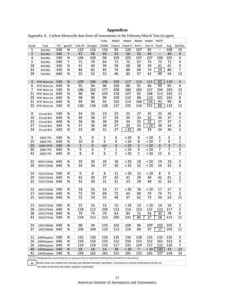
Appendix A. Carbon Monoxide data from all instruments in the February/March Test (in ppm)
Vista Makel Makel Makel Makel WSTF
Run# Fuel T/C Ignite? CSA-CP Draeger COMA Fixed-L Fixed-H Port-L Port-H PacIII Avg Std Dev 1 Std Mix 540 N 123 116 116 90 120 107 85 -- 108 15 2 Std Mix 540 Y 47 46 44 53 50 55 49 -- 49 4 4 Std Mix 540 N 106 100 98 109 103 107 107 108 105 4 5 Std Mix 540 Y 71 70 64 72 75 67 73 73 71 4 28 Std Mix 430 N 41 40 39 39 48 38 39 41 41 3 33 Std Mix 340 N 86 82 85 76 88 69 74 24 80 7 39 Std Mix 640 N 55 52 53 46 83 57 42 40 54 13
3 PFPI Wire Ins 540 N 109 106 106 109 117 115 111 92 110 4 6 PFPI Wire Ins 640 N 95 94 98 100 88 91 96 99 95 4 7 PFPI Wire Ins 540 N 186 182 177 200 180 184 157 194 183 13 21 PFPI Wire Ins 640 N 98 96 102 118 107 82 108 112 103 11 29 PFPI Wire Ins 640 N 98 96 99 109 110 88 110 101 101 8 31 PFPI Wire Ins 640 N 94 90 95 102 114 106 134 95 99 8 35 PFPI Wire Ins 540 N 130 126 128 127 145 116 151 88 132 12
8 Circuit Brd 540 N 24 26 23 23 25 27 35 25 26 4 10 Circuit Brd 640 N 40 38 37 39 39 33 32 39 37 3 23 Circuit Brd 640 N 36 36 39 39 34 35 22 37 37 2 27 Circuit Brd 340 N 37 36 38 27 39 25 < 20 38 34 6 34 Circuit Brd 430 N 33 30 31 27 < 20 28 24 34 30 3
9 100% TFE 540 N 5 0 5 6 < 20 8 < 20 5 5 3 15 100% TFE 640 N 10 8 9 9 < 20 8 < 20 7 9 1 20 100% PTFE 540 N 3 0 nd 4 < 20 5 < 20 0 3 2 30 100% TFE 640 N 9 6 7 2 < 20 9 < 20 7 7 3 42 100% TFE 640 N 8 6 6 5 < 20 2 < 20 12 6 3
22 90%T/10%K 640 N 19 20 20 16 < 20 18 < 20 19 19 2 36 90%T/10%K 640 N 34 34 37 30 < 20 32 < 20 24 32 4
14 75%T/25%K 540 N 9 8 8 11 < 20 12 < 20 8 9 2 19 75%T/25%K 640 N 42 40 37 42 41 39 44 42 41 2 32 75%T/25%K 640 N 32 30 31 31 23 28 48 31 32 7
12 50%T/50%K 540 N 18 16 14 17 < 20 18 < 20 17 17 2 17 50%T/50%K 640 N 72 70 69 72 64 69 74 74 71 3 25 50%T/50%K 640 N 52 54 55 46 37 62 73 56 54 11
13 25%T/75%K 540 N 15 14 13 15 < 20 13 < 20 14 14 1 18 25%T/75%K 640 N 118 112 109 113 114 123 122 122 117 5 38 25%T/75%K 640 N 79 74 79 63 83 72 93 35 78 9 43 25%T/75%K 540 N 218 212 213 200 231 86 37 28 215 11
24 10%T/90%K 640 N 98 94 103 102 108 96 109 102 102 5 37 10%T/90%K 640 N 106 104 110 113 119 84 97 17 105 11
11 100%Kapton 540 N 135 130 134 135 134 138 135 135 135 2 16 100%Kapton 640 N 156 150 153 152 150 152 152 162 153 4 26 100%Kapton 640 N 129 124 133 117 135 124 117 132 126 7 40 100%Kapton 540 N 18 16 14 38 < 20 7 < 20 109 19 12 41 100%Kapton 540 N 169 162 162 155 181 135 163 137 158 16
Shading denotes anomaly due to run sequence error or inadvertent (self) ignition (omitted from calculations)
XX Boxed values are omitted from average and standard deviation calculation. Conclusions on sensor performance should not
be drawn at this time until further analysis is performed.

American Institute of Aeronautics and Astronautics
18
Appendix B. HCN and acid gas data from all instruments in February/March Test (in ppm)
HX HBr Run# Fuel T/C Ignite? Draeger CSA-CP PAS PacIII Avg Std Dev CSA-CP Wet Trap Avg Std Dev HF ii HF iii Wet Trap Avg StdDev PacIII Wet Trap
1 Std Mix 540 N 2.2 1.2 2.4 -- 2 0.6 16 -- -- -- 0.22 0 -- 0.1 0.2 -- -- 2 Std Mix 540 Y 0.7 0.2 0.9 -- 1 0.4 3.7 -- -- -- 2.1 4.3 -- 3.2 1.6 -- -- 4 Std Mix 540 N 2.5 1.4 2.7 4 3 1 15.1 1.4 -- -- 0.2 0 0.4 0.2 0.2 0 0 5 Std Mix 540 Y 1.0 0.5 1.3 1.5 1 0.4 1.2 1.5 1.4 0.2 1.3 1.3 3.3 2.0 1.2 5.2 0 28 Std Mix 430 N 1.4 0.3 0.8 4.3 2 2 9.5 -- -- -- 0.2 0.4 -- 0.3 0.1 0.9 -- 33 Std Mix 340 N 1.8 1.3 2.1 3 2 1 6.7 0.8 0 0 0.3 0.1 0.2 0 0 39 Std Mix 640 N 1.5 0.5 0.8 3.4 2 1 14.8 3.2 0.4 0.2 1.2 0.6 0.5 0.5 0.1
3 PFPI Wire Ins 540 N 2.7 1.8 3.2 6.7 4 2 5.4 2.9 4.2 1.8 16.5 21.7 33.8 24 8.9 0 0 6 PFPI Wire Ins 640 N 0.8 0.5 1 1.4 1 0.4 5.1 4.9 5.0 0.1 6.5 7.2 121 6.9 0.5 29 0.1 7 PFPI Wire Ins 540 N 0.8 0.5 1.1 1.4 1 0.4 3.8 0.8 2.3 2.1 11.5 14.2 26.9 17.5 8.2 > 30 0 21 PFPI Wire Ins 640 N 0.8 0.6 0.8 1.2 1 0.2 0.8 0.1 0.5 0.5 12.5 10.7 34.5 19.2 13.3 > 30 0 29 PFPI Wire Ins 640 N 1.2 0.5 0.8 3.1 1 1 4.0 0.6 11.0 10 27.9 16.3 10.1 16.7 0.1 31 PFPI Wire Ins 640 N 1.2 0.6 1 2 1 1 2.2 0 8.4 6.3 3.4 6.0 2.5 19.5 0 35 PFPI Wire Ins 540 N 1.3 1.1 1.3 3.2 2 1 5.3 0.2 11.0 10.7 12.7 11.5 1.1 19.1 0
8 Circuit Brd 540 N 0.6 0.1 nd 1.6 1 1 14.1 0.6 0.6 0.9 4 1.8 1.9 2.5 1.7 10 Circuit Brd 640 N 0.7 nd nd 2.1 1 1 18.5 0.8 1.0 0.5 7.5 0.75 0.4 1.5 4.9 23 Circuit Brd 640 N 0.4 0.1 0.4 1.1 0 0.4 17.8 0.3 1.4 1.0 7.8 1.2 0.3 5.2 4.5 27 Circuit Brd 340 N 1 0.1 nd* 2.8 1 1 14.1 -- 0.6 0.5 -- 0.6 0.1 < 0.1 -- 34 Circuit Brd 430 N 0.8 0.1 nd 2 1 1 25.5 0.2 0.2 0 0.9 0.4 0.5 0 1.0
9 100% TFE 540 N 0.2 0.1 nd 1.6 1 1 3.4 1 3.9 6.9 186 5.4 2.1 21 0.4 15 100% TFE 640 N 0 nd nd 0.8 0 1 1.3 0 2.9 4.1 146 3.5 0.8 27 0 20 100% PTFE 540 N 0.2 0.2 nd 0.2 0 0.0 0.2 0.1 1.3 3.5 84.8 2.4 1.6 8.3 0 30 100% TFE 640 N 0 0.1 0.8 0.8 0 0.4 2.1 0 3.5 6.4 125 5.0 2.1 14.4 0 42 100% TFE 640 N 0 nd 1.4 0 0 1 1.2 0.6 1.6 3.3 37.3 2.5 1.2 8.8 0
22 90%T/10%K 640 N 0.8 0.3 0.9 0 0 0.4 0.6 0 3.9 4.4 139.2 4.2 0.4 25 0 36 90%T/10%K 640 N 1 0.5 1.4 2.5 1 1 2.8 0.2 3.9 6.4 37.6 5.2 1.8 0 0.1
14 75%T/25%K 540 N 0 nd nd 0.8 0 1 1.2 0.3 2.5 3.4 27.3 3.0 0.6 19.6 0 19 75%T/25%K 640 N 2.2 1.1 2.6 3.3 2 1 1.2 0.2 5 6.5 37 5.8 1.1 27.4 0 32 75%T/25%K 640 N 1.7 1.0 2.9 2.8 2 1 2.1 -- 5 5.6 -- 5.3 0.4 -- --
12 50%T/50%K 540 N 0.6 nd 0.4 1 1 0.3 1.3 0.4 2.2 2.4 73.4 2.3 0.1 11.2 0 17 50%T/50%K 640 N 3.6 2.7 4.5 5.5 4 1 2.1 0.4 3.9 5.3 71.3 4.6 1.0 21.8 0 25 50%T/50%K 640 N 2.6 2.3 3.3 3.4 3 0.5 2.6 0.2 3.9 4.5 26.7 4.2 0.4 14.3 0
13 25%T/75%K 540 N 0 nd nd 0.8 0 1 1.0 0.2 1.2 1.0 17.4 1.1 0.1 8.4 0 18 25%T/75%K 640 N 3.8 3.0 5 5.7 4 1 1.9 0.3 2.9 2.6 38.1 2.8 0.2 15.5 0 38 25%T/75%K 640 N 1.7 1.5 2 2.6 2 0.5 0.9 0.3 1.8 1.7 19.1 1.8 0.1 4.5 0 43 25%T/75%K 540 N 7.5 7.9 11.8 11.8 10 2 3.2 0.2 5.2 6 9 6.7 2.0 8.8 0
24 10%T/90%K 640 N 1.8 1.4 2.2 1.1 2 0 3.3 0.1 1.2 1.2 4.9 2.4 2.1 4 0 37 10%T/90%K 640 N 2.7 2.8 3.8 5.1 4 1 3.1 0.7 1.7 1.5 1 1.4 0.4 0 0.1
11 100%Kapton 540 N 4.2 3.4 5.6 5.9 5 1 3.3 0.2 0 0 0.4 0.1 0.2 0 0 16 100%Kapton 640 N 5.3 4.2 7.2 7.7 6 2 3.6 0.2 0.5 0.5 4.1 1.7 2.1 3.5 0 26 100%Kapton 640 N 3.0 2.6 3.9 4.9 4 1 2.5 0.1 0.2 0 0.7 0.3 0.4 1 0 40 100%Kapton 540 N 0.9 0.3 0.5 2 1 1 2.1 0 0 0 0.8 0.3 0.5 0 0 41 100%Kapton 540 N 5.8 5.6 8 9.2 7 2 3.4 0.1 0 0 0.4 0.1 0.2 0 0
Shading denotes anomaly due to run sequence error or inadvertent (self) ignition (omitted from calculations) XX Boxed values are omitted from average and standard deviation calculation. Conclusions on sensor performance should not
be drawn at this time until further analysis is performed.
HCN HCL HF

American Institute of Aeronautics and Astronautics
19
Appendix C. Carbon Monoxide data from all sources for the September 2012 test (in ppm)
Fuel Temp Date Time Ash Draeger Vista Makel Makel Makel Makel WSTF Run Run Fuel Run # 0.5 g C local g CSA-CP Xam5600 COMA Fixed-L Fixed-H Port-L Port-H PacIII Avg Std Dev Stats
1 Nomex 640 10-Sep 2:44 0.028 89 84 87 83 92 98 154 92 89 5 2 " " " 3:11 0.046 118 112 129 125 103 152 110 127 122 15 3 " " " 3:34 0.045 119 116 161 118 105 146 114 130 126 19 4 " " " 4:00 0.014 92 92 121 92 113 90 99 104 100 11 5 " " " 4:23 0.042 100 102 116 112 127 55 99 111 110 10 6 Nomex 640 11-Sep 8:54 0.153 65 60 52 65 101 68 96 68 7 " " " 9:15 0.091 105 100 87 93 108 102 84 113 99 10
excl #6 Avg 104 101 117 104 108 118 101 113 108 excl #6 StdDev 13 12 28 17 12 29 12 14 18
8 M22759 ins 640 " 9:36 0.046 53 54 44 47 76 32 70 58 9 " " " 10:06 0.021 76 78 59 82 81 74 85 82 77 8
10 " " " 10:30 0.017 72 72 55 83 73 79 76 79 74 8 11 " " " 10:53 0.021 78 80 61 90 65 59 62 85 73 12 12 " " " 11:16 0.030 68 72 56 90 69 75 70 78 72 10 13 " " " 11:37 0.017 72 76 60 90 69 75 70 82 74 9
excl #8 Avg 73 76 58 87 71 72 73 81 74 excl #8 StdDev 4 4 3 4 6 8 9 3 9
14 PTFE granules 640 " 2:25 0.041 9 14 10 7 8 11 3 14 10 3 15 " " " 2:48 0.014 10 14 9 9 3 9 5 14 10 3 16 " " " 3:13 0.010 4 8 5 6 7 11 5 7 7 2 17 " " " 3:38 0.015 8 12 8 12 10 14 7 11 10 2 18 Kapton chips 640 " 4:07 0.227 266 268 215 295 226 206 205 285 246 37 19 " " " 4:31 0.278 233 224 187 244 218 108 128 259 228 25 20 " " " 4:52 0.251 294 282 239 293 316 131 168 324 291 30 21 Kapton powder 640 12-Sep 9:10 0.126 292 272 232 292 273 218 301 325 276 36 22 " " " 9:36 0.112 272 270 211 261 301 218 214 389 250 35
All Kapton Avg 271 263 217 277 267 214 240 316 258 StdDev 25 23 20 23 44 7 53 49 38
23 PTFE powder 640 12-Sep 9:56 0 24 28 21 16 10 8 0 31 24 " " " 10:16 0.006 7 12 6 7 8 5 8 10 8 2 25 " " " 10:37 0.008 8 14 8 10 8 11 11 11 10 2 26 " " " 10:56 0.009 9 14 10 12 8 11 11 12 11 2
All PTFE excl #23 Avg 8 13 8 9 8 10 8 11 9 StdDev 2 2 2 2 1 3 3 2 3
27 PCB 340 12-Sep 12:42 0.366 11 14 10 8 15 -- -- 13 13 2 28 " " " 1:02 0.352 20 22 16 19 29 -- -- 23 22 4 29 " 440 " 1:22 0.344 23 26 19 26 32 -- -- 26 25 4 30 " " " 1:42 0.323 25 28 20 27 43 -- -- 29 29 8 31 " 540 " 2:07 0.321 28 30 22 29 39 -- -- 31 30 5 32 " " " 2:30 0.335 25 28 22 27 35 -- -- 29 28 4 33 " 640 " 2:50 0.308 36 38 27 43 40 -- -- 40 37 6 34 " " " 3:18 0.302 34 36 27 41 36 -- -- 38 35 5
Shading denotes anomaly due to run sequence error or inadvertent (self) ignition; data excluded from statistics PCB 640C Avg 36 XX Boxed values are omitted from average and standard deviation calculation. Conclusions on sensor performance
should not be drawn at this time until further analysis is performed.
PCB 640C StdDev 5

American Institute of Aeronautics and Astronautics
20
Appendix C continued … (concentrations in ppm)
Fuel Temp Date Time Ash Draeger Vista Makel Makel Makel Makel WSTF Run Run Fuel Run # 0.5 g C local g CSA-CP Xam5600 COMA Fixed-L Fixed-H Port-L Port-H PacIII Avg Std Dev Stats
35 100% PVC 640 12-Sep 3:36 0.009 66 66 48 -- -- -- -- 38 60 10 36 50/50 P/K 640 13-Sep 8:38 0.046 246 230 249 240 182 58 315 270 258 31 37 " " " 8:59 0.061 253 246 256 265 236 211 278 283 254 23 38 " " " 9:18 0.111 80 80 80 85 143 113 186 39 " " " 9:35 0.042 286 280 298 330 271 357 245 321 299 36
Avg 262 252 268 278 254 284 279 291 271 StdDev 21 26 27 46 25 103 35 27 36
40 25/75 P/K 640 " 9:54 0.092 301 286 311 340 248 357 218 334 311 37 41 " " " 10:12 0.074 378 356 398 419 344 378 288 426 373 45 42 " " " 10:31 0.128 156 138 132 123 159 107 166 144 43 " " " 10:54 0.074 370 346 386 361 333 297 249 422 346 54
Avg 350 329 365 373 308 344 269 394 345 StdDev 42 38 47 41 53 42 28 52 51
44 10/90 P/K 640 " 12:29 0.088 392 370 415 353 180 182 202 436 393 33 45 " " " 12:48 0.139 228 220 238 198 137 73 151 250 46 " " " 1:06 0.088 440 414 464 414 309 202 323 480 406 66
Avg 416 392 439.5 384 309 -- 323 458 401 StdDev 34 31 35 43 -- -- -- 31 53
47 75/25 P/K 640 " 1:32 0.031 138 134 148 117 126 38 128 154 135 13 48 " " " 1:50 0.047 53 60 56 52 114 61 152 60 49 " " " 2:10 0.011 95 94 103 89 94 98 112 107 99 8 50 " " " 2:30 0.021 120 118 131 124 124 118 139 135 126 8
Avg 118 115 127 110 115 108 126 132 119 StdDev 22 20 23 19 18 14 14 24 18
51 90/10 P/K 640 " 2:53 0.016 77 76 83 72 81 55 87 87 77 10 52 " " " 3:12 0.007 73 72 78 69 71 63 61 81 71 7 53 " " " 3:30 0.010 55 56 59 55 72 40 53 63 59 7
Avg 68 68 73 65 75 53 67 77 68 StdDev 12 11 13 9 6 12 18 12 12
54 90/10 P/PVC 640 " 3:47 0.002 37 38 39 41 29 35 33 43 37 4 55 " " " 4:06 0.002 24 26 28 31 33 29 31 30 29 3 56 " " " 4:24 0.001 27 28 28 39 27 33 28 32 30 4
Avg 29 31 32 37 30 32 31 35 32 StdDev 7 6 6 5 3 3 3 7 5
57 PCB+PVC1 640 14-Sep 8:33 0.297 47 44 49 46 56 0 67 49 51 8 58 " " " 8:56 0.347 43 42 46 44 57 35 61 47 47 8 52 59 " " " 9:17 0.312 57 50 63 58 68 54 58 55 58 6 8 60 PCB+PVC2 640 " 9:39 0.303 55 52 -- 61 73 50 59 59 58 8 61 61 " " " 10:05 0.301 62 62 65 69 72 47 61 69 63 8 8 62 PTFE/PVC2 " " 10:28 0.004 34 36 38 29 27 29 33 40 33 5
Shading denotes anomaly due to run sequence error or inadvertent (self) ignition; data excluded from statistics
XX Boxed values are omitted from average and standard deviation calculation. Conclusions on sensor performance should not be drawn at this time until further analysis is
performed.

American Institute of Aeronautics and Astronautics
21
Appendix D. HCN and acid gas results for the Sep 2012 test (in ppm)
HCN HCL HF HX HBr Run Fuel T/C Draeger CSA-CP PAS PacIII Avg StdDev CSA-CP HCPM Wet Trap Avg StdDev HCPM Hfiii Wet Trap Avg StdDev PacIII Wet Trap
1 Nomex 640 5.7 5.7 8.4 6.7 7 2 20 nd 0.2 nd nd nd nd -- nd 2 " " 6.4 6.2 9.4 7.6 7 1 25 nd nd nd nd nd nd -- nd 3 " " 7.8 7.3 10.8 8.7 9 2 26 nd 0.3 nd nd nd nd -- nd 4 " " 5.4 5.3 7.3 6.3 6 1 26.5 nd 0.3 nd nd nd nd -- nd 5 " " 6.1 5.9 8.7 7.1 7 1 28 nd 0.4 nd nd nd nd -- nd 6 " " 6.0 5.8 8.1 7.2 7 1 18.1 nd 0.1 nd nd nd nd -- 7.1 7 " " 8.1 7.8 10.4 9.5 9 1 25 nd 0.1 nd nd nd nd -- 19.3
Avg 6.5 6.3 9.0 7.6 7.3 StDev 1.0 0.9 1.3 1.1 1.5
8 M22759 ins 640 3.4 3.3 4.4 4.2 4 1 6.8 nd 0.0 7.1 4 9.2 7 3 29.4 9 " " 3.4 3.1 4.4 4.2 4 1 6.5 nd 1.4 8 6.5 11.2 9 2 30.0
10 " " 4.0 3.6 4.9 4.8 4 1 7.7 nd 1.2 10.5 8.8 27.9 10 1 30.0 11 " " 3.8 3.4 4.7 4.7 4 1 7.2 nd 0.1 12.3 11.3 20.5 15 5 30.0 12 " " 3.9 3.5 5 4.8 4 1 6.6 nd 0.1 13.3 12.2 24 13 1 27.6 13 " " 3.7 3.1 4.7 4.6 4 1 5.6 nd 0.1 12.8 14.2 13.9 14 1 30.0
Avg 3.7 3.3 4.7 4.6 4.1 6.7 nd 0.5 10.7 9.5 13.7 11 29.5 StDev 0.3 0.2 0.2 0.3 0.6 0.7 nd 0.6 2.6 3.8 4.9 4 1.0
14 PTFE granules 640 nd 0.1 nd 0.6 1.3 nd 10.1 12.9 12 2 30 15 " " nd 0 nd 0.3 1.3 nd 0.1 14.7 17.4 45.7 16 2 30 16 " " nd -0.2 nd 0.3 1.1 nd 0.1 8.6 15.1 21.6 15 7 0 17 " " nd -0.2 nd 0.2 1.2 nd 10.7 15.2 13 3 0 18 Kapton chips 640 10.2 8.9 13.6 12.0 11 2 10 nd nd 1.7 1.8 3.4 2 1 nd 19 " " 7.7 6.7 9.6 9.2 8 1 8.7 nd nd 0.8 nd 1.4 1 nd nd 20 " " 12.3 11.2 15.6 14.2 13 2 12.3 nd 0.2 0.6 nd 1.0 1 nd nd 21 Kapton powder 640 8.1 8.4 11.6 10.2 10 2 14 nd nd nd nd nd 22 " " 7.5 7.8 10.7 9.9 9 2 15 nd nd nd nd nd
all Kapton Avg 9.2 8.6 12.2 11.1 10.3 nd nd nd 1 StDev 2.1 1.7 2.4 2.0 2.4 0.8
23 PTFE powder 640 nd 0.1 nd 0.5 2.0 nd 0.1 7.2 7.6 14.6 10 4 17.6 24 " " nd -0.3 nd 0.4 1.4 nd 0.0 7 11.3 32.2 9 3 12.7 25 " " nd -0.1 nd 0.3 1.3 nd 0.2 9.5 14.4 24.5 16 8 17.3 26 " " nd -0.2 nd 0.1 1.3 nd 0.1 11.8 17.6 22.2 17 5 19.4 0.9
all PTFE Avg nd nd nd 0.3 nd 0.1 nd 10.0 13.9 20.7 13 16.8 StDev 0.2 2.5 3.3 4.3 5 2.9
27 PCB 340 nd 0.1 nd 0.3 10.2 nd 0.0 0.5 0.7 0.6 0.1 nd nd 28 " " nd 0.1 nd 0.3 13.5 nd 0.3 0.7 0.5 0.3 nd 29 " 440 nd 0.1 nd 0.3 17 nd 0.1 0.3 0.4 1.5 0.7 0.7 nd 1.8 30 " " nd 0.1 nd 0.4 16.2 nd 0.0 0.4 0.1 0.9 0.5 0.4 nd 0.8 31 " 540 nd 0.1 nd 0.4 17 nd 0.2 0.4 0.1 1.1 0.5 0.5 0.8 2.3 32 " " nd 0.1 nd 0.4 16.6 nd 0.1 0.4 0.5 1.0 0.6 0.3 0.9 2.2 33 " 640 nd 0.1 nd 0.5 19.8 nd 0.2 0.4 0.4 1.5 0.8 0.6 1.3 1.0 34 " " nd 0.1 nd 0.6 18 nd 0.1 0.4 0.3 1.2 0.6 0.5 0.9 1.0
Avg nd nd avg at 640C 0.7 1.0 StDev stdev at 640C 0.5
Shading denotes anomaly due to run sequence error or inadvertent (self) ignition; data excluded from statistics XX Boxed values are omitted from average and standard deviation calculation. Conclusions on sensor performance should not be drawn at
this time until further analysis is performed.

American Institute of Aeronautics and Astronautics
22
Appendix D continued…. (concentrations in ppm)
HCN HCL HF HX HBr Run # Fuel T/C Draeger CSA-CP PAS PacIII Avg StdDev CSA-CP HCPM Wet Trap Avg StdDev HCPM Hfiii Wet Trap Avg StdDev PacIII Wet Trap
35 100% PVC 640 7.3 0.2 nd 8.4 4 > 99 252 59.9 4.4 6.3 14 8 > 30 0.4 36 50/50 P/K 640 5.9 6.2 8.7 7.6 7 1 6 0.6 0.6 0.6 3.3 3.3 19.3 4.7 0.2 37 " " 8.9 8.2 11.6 9.3 10 1 6.6 0.6 0.5 0.6 6.5 6.9 21.6 9.0 0.1 38 " " 3.5 3.3 4.5 7.7 0.4 5.3 6.1 39 " " 10.2 9.2 13.4 12 11 2 8.2 0.8 0.7 0.8 8.6 10.3 24.4 11.5 0.1
Avg 8 7.9 11.2 9.6 9.3 0.6 0.1 StDev 2 1.5 2.4 2.2 2.3 0.1
40 25/75 P/K 640 8.9 8.2 12.2 10.4 10 2 9.5 nd 0.7 7.6 9.3 11.3 9.4 nd 41 " " 11.8 10.4 16.2 13.6 13 3 10.5 nd 0.5 7.8 9.9 8.9 5.3 nd 42 " " 4.1 4.1 5 4.4 6.2 nd 0.1 7.8 9.4 2.8 4.5 nd 43 " " 11.6 10.4 15.6 13.1 13 2 10 nd 0.5 8.2 10 9.5 5.1 nd
Avg 10.8 9.7 14.7 12.4 11.9 9.2 nd StDev 1.6 1.3 2.2 1.7 2.5 1.2
44 10/90 P/K 640 11.8 11.2 15.9 13.4 9.1 nd 0.2 2.2 2.4 4.5 1.6 nd 45 " " 7.2 7.0 9.6 8.2 6.9 nd nd 2.4 2.7 2.4 1.7 nd 46 " " 14.4 13.1 19.2 15.2 9.3 nd 0.1 2.5 3 3.3 1.7 nd
Avg 13.1 12.2 17.6 14.3 14.3 nd 3.0 nd StDev 1.8 1.3 2.3 1.3 2.5
47 75/25 P/K 640 5.5 4.6 7.2 6.0 4.8 nd 0.1 9.1 13.6 16.6 5.4 nd 48 " " 2.8 2.4 3.7 3.2 3.7 0.8 0.6 10 13 20.1 6.8 nd 49 " " 4.1 3.4 5.5 4.7 5 0.8 0.5 11.3 15.2 23.9 7.3 nd 50 " " 4.3 3.7 5.7 4.9 5.7 0.4 0.4 14.3 18.7 23.9 9.0 nd
Avg 4.6 3.9 6.1 5.2 5.0 0.4 nd StDev 0.8 0.6 0.9 0.7 1.1 0.3
51 90/10 P/K 640 3.1 2.2 3.7 3.3 4.3 0.6 0.2 10 14.9 28.4 8.5 nd 52 " " 2.7 1.6 3.7 3.1 4.9 0.4 15.3 21.4 10.5 nd 53 " " 2.3 1.3 3.2 2.8 4.5 0.6 16.9 22.5 10.8 nd
Avg 2.7 1.7 3.5 3.1 2.8 0.5 nd StDev 0.4 0.5 0.3 0.3 0.8 0.2
54 90/10 P/PVC 640 0.6 0 nd 0.6 26.5 25 6.4 17.9 24 29.4 14.3 nd 55 " " 0.6 0 nd 0.8 35 29.2 9.6 17.1 22.8 30.2 13.5 nd 56 " " 0.6 0.1 nd 0.7 43 29.2 9.4 18.3 24 33 13.1 nd
Avg 0.6 0.0 nd 0.7 0.4 18.1 13.6 nd StDev nd 0.1 0.1 0.3 10.8 0.6
57 PCB+PVC1 640 nd 0.2 nd 1.3 19 23 3.7 1.0 1.3 1.5 0.7 2 58 " " 0.5 0.2 nd 1.5 35 28.4 5.1 1.0 1.1 1.3 0.8 1 59 " " 0.6 0.2 nd 1.9 44.7 29.4 1.1 1.4 0.7
Avg 0.8 StDev 0.7
60 PCB+PVC2 640 1.3 0.2 nd 2.5 97 62.2 21.3 1.3 1.7 4 2.5 3.7 61 " " 1.4 0.2 nd 2.5 86.5 60 15.1 1.2 1.5 1.5 2.6 1.1
Avg StDev
62 PTFE/PVC2 " 1.9 0.2 nd 2.5 99+ 67.8 7.2 8.6 2.8 Shading denotes anomaly due to run sequence error or inadvertent (self) ignition; data excluded from statistics
XX Boxed values are statistical outliers omitted from average and standard deviation calculation. Conclusions on sensor performance should not be drawn at this time until further analysis is performed.

American Institute of Aeronautics and Astronautics
23
Appendix E. Aerosol Mass Concentration and Ash Data for February/March 2012 Test
Feb/Mar
2012
TestDates
Test
No. Material Temp, C
TEOM Mass
Conc mg/m^3
TEOM Mass
Conc g/m^3
Thermal
Precipitator
Aerosol
Number
Concentration,
#/cm^3
Estimated
Mass of
Particles, g
Ash Mass,
g
2/27/2012 1 Std Mix 540 11.91 0.0119 Y 0.0074 0.0119
2 " 540 65.09 0.0651 Y 0.0405 0.0651
Day 1 3 wire insulation 540 6.80 0.0068 Y 0.0042 0.0068
2/28/2012 4 Std Mix 540 106.52 0.1065 Y 4.90E+06 0.0664 0.1065
5 " 540 67.01 0.0670 Y 4.33E+06 0.0417 0.0670
6 wire insulation 640 14.42 0.0144 Y 3.31E+06 0.0090 0.0144
7 " 540 10.16 0.0102 3.28E+06 0.0063 0.0102
8 Circuit Bd 540 54.14 0.0541 Y 3.60E+06 0.0337 0.0541
9 100% TFE 540 95.64 0.0956 Y 4.30E+06 0.0596 0.0956
10 Circuit Bd 640 107.19 0.1072 4.53E+06 0.0668 0.1072
11 100%Kapton 540 7.21 0.0072 Y 3.40E+06 0.0045 0.0072
12 50%TFE 50% Kap 540 4.81 0.0048 Y 1.57E+06 0.0030 0.0048
13 25%TFE 75%Kap 540 14.16 0.0142 Y 1.24E+06 0.0088 0.0142
14 75%TFE 25%Kap 540 13.19 0.0132 Y 1.83E+06 0.0082 0.0132
15 100% TFE 640 13.61 0.0136 Y 2.44E+06 0.0085 0.0136
16 100%Kapton 640 12.84 0.0128 Y 0.0080 0.0128
17 50%TFE 50% Kap 640 49.25 0.0492 Y 2.33E+06 0.0307 0.0492
18 75%TFE 25%Kap 640 29.57 0.0296 Y 2.19E+06 0.0184 0.0296
Day 2 19 75%TFE 25%Kap 640 22.76 0.0228 Y 2.03E+06 0.0142 0.0228
2/29/2012 20 100% TFE 540 2.40 0.0024 Y 1.16E+06 0.0015 0.0024
21 wire insulation 640 21.06 0.0211 2.41E+06 0.0131 0.0211
22 90%TFE 10%Kap 640 8.35 0.0083 1.95E+06 0.0052 0.0083
23 Circuit Bd 640 77.09 0.0771 Y 4.17E+06 0.0480 0.0771
24 10%TFE 90%Kap 640 62.13 0.0621 2.44E+06 0.0387 0.0621
25 50%TFE 50% Kap 640 25.73 0.0257 Y 2.04E+06 0.0160 0.0257
26 100%Kapton 640 9.19 0.0092 2.24E+06 0.0057 0.0092
27 Circuit Bd 340 110.96 0.1110 Y 3.80E+06 0.0691 0.1110
28 Std Mix 430 96.95 0.0969 Y 2.35E+06 0.0604 0.0969
29 wire insulation 640 16.83 0.0168 Y 2.85E+06 0.0105 0.0168
30 100% TFE 640 10.78 0.0108 1.71E+06 0.0067 0.0108
31 wire insulation 640 11.68 0.0117 2.21E+06 0.0073 0.0117
Day 3 32 75%TFE 25%Kap 640 24.09 0.0241 2.01E+06 0.0150 0.0241
3/1/2012 33 Std Mix 340 131.31 0.1313 4.27E+06 0.0818 0.1313
34 Circuit Bd 430 95.82 0.0958 2.83E+06 0.0597 0.0958
35 wire insulation 540 11.08 0.0111 Y 2.87E+06 0.0069 0.0111
36 90%TFE 10%Kap 640 71.28 0.0713 Y 3.57E+06 0.0444 0.0713
37 10%TFE 90%Kap 640 29.57 0.0296 2.16E+06 0.0184 0.0296
38 25%TFE 75%Kap 640 21.91 0.0219 Y 1.62E+06 0.0136 0.0219
39 Std Mix 640 49.61 0.0496 3.02E+06 0.0309 0.0496
40 100%Kapton 540 2.40 0.0024 1.26E+06 0.0015 0.0024
41 100%Kapton 540 7.21 0.0072 1.85E+06 0.0045 0.0072
42 100% TFE 640 12.96 0.0130 Y 1.45E+06 0.0081 0.0130
Day 4 43 25%TFE 75%Kap 540 44.92 0.0449 2.39E+06 0.0280 0.0449

American Institute of Aeronautics and Astronautics
24
Appendix F. Particle mass concentration and ash data for the Sep 2012 Test
Note: Grey cells denote anomaly due to run sequence error or inadvertent self-ignition; omit from averages, or no
data available for this test. No aerosol mass concentration data collected for runs 59-62
Sep 2012
TestDates
Test
No.Material
TEOM Mass
Conc g/m^3
Avg Mass
Conc, g/m^3
standard
dev, g/m^3
Aerosol Mass
Fraction below
1 μm
Aerosol
Number
Concentration,
#/cm^3
Avg Number
Conc,
#/cm^3
standard dev,
#/cm^3
Est mass of
particles, g
Ash Mass
(g)
9/10/2012 1 NOMEX 0.0774 0.0482 0.028
2 " 0.0440 TP 4.82E+06 0.0274 0.046
3 " 0.0718 4.52E+06 0.0447 0.045
4 " 0.0647 4.85E+06 0.0403 0.014
5 " 0.0727 4.55E+06 0.0453 0.042
Day 1 6 " 0.0639 (omit from avg) 5.62E+06 0.0398 0.153
9/11/2012 7 " 0.0622 TP 5.72E+06 0.0387 0.091
average & st dev 0.0655 0.0119 4.89E+06 4.87E+05 0.0408 0.044
8 wire insulation 0.0705 (omit from avg) 5.95E+06 0.046
9 " 0.0559 4.29E+06 0.0348 0.021
10 " 0.0435 4.07E+06 0.0271 0.017
11 " 0.0493 3.96E+06 0.0307 0.021
12 " 0.0478 4.29E+06 0.0297 0.030
13 " 0.0542 3.91E+06 0.0337 0.017
average & st dev 0.0501 0.0050 4.10E+06 1.78E+05 0.0312 0.021
14 100% PTFE 0.0367 1 4.28E+06 0.0229 0.041
15 " 0.0335 0.994 4.84E+06 0.0209 0.014
16 " 0.0344 1 3.25E+06 0.0214 0.010
17 " 0.0503 0.988 2.52E+06 0.0313 0.015
average & st dev 0.0387 0.0078 3.73E+06 1.04E+06 0.0241 0.020
18 kapton squares 0.0049 0.993 2.90E+06 0.0031 0.227
19 " 0.0024 0.996 2.94E+06 0.0015 0.278
20 " 0.0036 1 3.01E+06 0.0022 0.251
Day 2 average & st dev 0.0036 0.0013 2.95E+06 5.58E+04 0.0023 0.252
9/12/2012 21 granulated kapton 0.0179 0.982 4.41E+06 0.0112 0.126
22 " 0.0194 0.984 4.32E+06 0.0121 0.112
average & st dev 0.0187 0.0011 4.36E+06 6.13E+04 0.0116 0.119
23 PTFE powder (100 um) 0.0173 (omit from avg) 0.982 3.30E+06 0
24 " 0.0550 0.999 5.20E+06 0.0343 0.006
25 " no data 0.998 4.96E+06 no data 0.008
26 " 0.0516 0.997 4.98E+06 0.0321 0.009
average & st dev 0.0533 0.0024 5.05E+06 1.32E+05 0.0332 0.008
27 340 PCB 0.0557 0.936 4.00E+06 0.0347 0.366
28 " 0.0651 TP 0.928 4.12E+06 0.0406 0.352
average & st dev 0.0604 0.0066 4.06E+06 8.33E+04 0.0376 0.359
29 440 PCB 0.0580 0.922 5.43E+06 0.0361 0.344
30 " 0.0742 TP 0.922 5.35E+06 0.0462 0.323
average & st dev 0.0661 0.0115 5.39E+06 5.58E+04 0.0412 0.334
31 540 PCB 0.0885 TP 0.922 6.20E+06 0.0551 0.321
32 " 0.0885 0.923 5.88E+06 0.0551 0.335
average & st dev 0.0885 0.0000 6.04E+06 2.25E+05 0.0551 0.328
33 640 PCB 0.1070 TP 0.926 6.66E+06 0.0667 0.308
34 " 0.1110 0.911 6.32E+06 0.0692 0.302
average & st dev 0.1090 0.0028 6.49E+06 2.43E+05 0.0679 0.305
35 PVC 0.1150 0.893 6.11E+06 0.0716 0.009
Day 3 0.1150 6.11E+06

American Institute of Aeronautics and Astronautics
25
Appendix F. continued…
Acknowledgments
Certain commercial entities, equipment, or materials may be identified in this document in order to describe an
experimental procedure or concept adequately. Such identification is not intended to imply recommendation or
endorsement by the National Aeronautics and Space Administration, nor is it intended to imply that the entities,
materials, or equipment are necessarily the best available for the purpose.
References
1. Ruff, G. A., Greenberg, P. S., Mudgett, P. D., Hornung, S. D., Pilgrim, J. S., Vakhtin, A. B, “Towards the
Ientification of Chemical Markers for Spacecraft Post-fire Cleanup,” 41st
International Conference On Environmental Systems, SAE, Portland, OR, 17-21 July 2011, AIAA 2011-5052.
2. Sribnik,F., Birbara, P.J., Faszcza, J. J., and Nalette, T. A., “Smoke and Contaminant Removal System for Space Station,” SAE Paper 901390, 20
th Intersociety Conference on Environmental Systems, Williamsburg, VA, July
9-12, 1990. 3. Pilgrim, Jeffrey S. “Advanced Fire Detector for Space Applications,” NASA Tech Briefs, 36, No. 6 (2012), 90. 4. Pilgrim, Jeffrey S. “Rugged, Portable, Real-Time Optical Gaseous Analyzer for Hydrogen Fluoride,” NASA
Tech Briefs, 36, No. 10, (2012), 25.
5. Hunter, G. W., Xu, J. C., Biaggi-Labiosa, A. M., Ward, B., Dutta, P., and Liu, C. C., “Smart Sensor System for
Spacecraft Fire Detection and Air Quality Monitoring,” 41st
International Conference On Environmental Systems, SAE, Portland, OR, 17-21 July 2011, AIAA 2011-5021.
6. Hunter, G. W., Greenberg, P. S., Xu, J. C., Ward, B., Makel, D., Dutta, P., and Liu, C. C., “Miniaturized Sensor
Systems for Early Fire Detection in Spacecraft,” 39th
International Conference On Environmental Systems, SAE, Warrendale, PA, 12-16 July 2009, 09ICES-0335.
9/13/2012 36 50-50 teflon/kapton 0.0358 0.993 4.36E+06 0.0223 0.046
37 (100 um teflon powder/ 0.0252 0.988 3.82E+06 0.0157 0.061
38 granulated kapton) 0.0364 (omit from avg) 0.993 4.03E+06 0.111
39 " 0.0394 0.995 3.95E+06 0.0245 0.042
average & st dev 0.0334 0.0074 4.04E+06 2.83E+05 0.0208 0.050
40 25-75 teflon/kapton 0.0284 0.994 3.81E+06 0.0177 0.092
41 (100 um teflon powder/ 0.0254 0.991 3.75E+06 0.0158 0.074
42 granulated kapton) 0.0252 0.988 3.66E+06 0.0157 0.128
43 " 0.0270 0.993 3.55E+06 0.0168 0.074
average & st dev 0.0265 0.0015 3.69E+06 1.16E+05 0.0165 0.080
44 10-90 teflon/kapton 0.0129 0.996 3.29E+06 0.0080 0.088
45 (100 um teflon powder/ 0.0140 (omit from avg) 0.988 3.30E+06 0.139
46 granulated kapton) 0.0117 0.993 3.76E+06 0.0073 0.088
average & st dev 0.0123 0.0008 3.52E+06 3.33E+05 0.0076 0.088
47 75-25 teflon/kapton 0.0498 0.996 3.18E+06 0.0310 0.031
48 (100 um teflon powder/ 0.0250 (omit from avg) 0.977 3.68E+06 0.047
49 granulated kapton) 0.0440 0.996 3.80E+06 0.0274 0.011
50 " 0.0512 0.996 3.29E+06 0.0319 0.021
average & st dev 0.0483 0.0038 3.42E+06 3.33E+05 0.0301 0.021
51 90-10 teflon/kapton 0.0171 1 3.19E+06 0.0106 0.016
52 (100 um teflon powder/ 0.0349 0.997 3.48E+06 0.0218 0.007
53 granulated kapton) 0.0378 0.0364 0.0020 0.995 3.93E+06 w/o outlier (#51) 0.010
average & st dev 0.0299 0.0112 3.54E+06 3.71E+05 0.0187 0.011
54 90-10 teflon/PVC 0.1113 0.969 4.33E+06 0.0693 0.002
55 (100 um teflon powder/ 0.1386 0.944 4.35E+06 0.0863 0.002
56 granulated PVC) 0.1301 0.945 5.97E+06 0.0810 0.001
Day 4 average & st dev 0.1343 0.0060 4.88E+06 9.42E+05 0.0837 0.002
9/14/2012 57 PCB+PVC1 0.0497 5.99E+06
58 " 0.1110 5.88E+06
59 " 5.82E+06
average & st dev 0.1110 0.0433 5.90E+06 8.62E+04
60 PCB+PVC2 5.83E+06
61 " 4.66E+06
Day 5 average & st dev 5.25E+06 8.23E+05