Embed Size (px)
DESCRIPTION
mechanical
Citation preview
CLICK BOND, INC. 2151 LOCKHEED WAY CARSON CITY, NV 89706-0713 PHONE: 775-885-8000 CAGE CODE: 66530 FAX: 775-883-0191
CBPS-206 Rev. E PAGE 1 OF 15 6JUN05
ADHESIVE BONDING OF NUTPLATES, STUDS, STANDOFFS, CABLE TIE MOUNTS, BUSHINGS, AND OTHER FASTENERS.
1. SCOPE 1.1 This process specification establishes procedures for bonding various studs,
standoffs, cable tie mounts, nutplates, bushings, and other fasteners. The adhesives specified are 2-part acrylic and epoxy adhesives which cure at room temperature.
2. REQUIREMENTS 2.1 Materials 2.1.1 Adhesives 2.1.1.1 Pre-proportioned Adhesive Foil Pack Kit Click Bond, Inc.
Click Bond CB91 Kit contains: 1 ea. CB200, 3.5 gram packet of unmixed Lord® 201 Base and Accelerator 17 1 ea. Mixing Stick 1 ea. Plastic Mixing Plate 1 ea. Mixing Instruction Card
Packaged in a Plastic Bag. 2.1.1.2 Pre-proportioned Adhesive Foil Pack Kit Click Bond, Inc.
Click Bond CB92 Kit contains: 1 ea. CB200, 3.5 gram packet of unmixed Lord® 201 Base and Accelerator 17 1 ea. Mixing Stick 1 ea. Plastic Mixing Plate 1 ea. Solvent Wipe 1 ea. Abrasive Pad 1 ea. Mixing Instruction Card
Packaged in a Plastic Bag. 2.1.1.3 Pre-proportioned Adhesive Foil Pack Kit Click Bond, Inc.
Click Bond CB93 Kit contains: 1 ea. CB300, 4 gram packet of unmixed Hardman Red Double Bubble® (Epoweld® 8173) 1 ea. Mixing Stick 1 ea. Plastic Mixing Plate 1 ea. Mixing Instruction Card
Packaged in a Plastic Bag.
CBPS-206 PROCESS SPECIFICATION
CBPS-206 PROCESS SPECIFICATION
2.1.1 Adhesives (CONTINUED) 2.1.1.4 Pre-proportioned Adhesive Dispenser Kit Click Bond, Inc.
Click Bond CB200-40 Kit contains: 1 ea. 40-ml Dual Pack Cartridge of unmixed Lord® 201 Base and Accelerator 17
2.1.1.5 Pre-proportioned Adhesive Dispenser Kit Click Bond, Inc. Click Bond CB250-50 Kit contains:
1 ea. 50-ml Dual Pack Cartridge of unmixed ITW Plexus™ MA300
2.1.1.6 Pre-proportioned Adhesive Dispenser Kit Click Bond, Inc. Click Bond CB309-50 Kit contains:
1 ea. 50-ml Dual Pack Cartridge of unmixed Lord® 309 2.1.1.7 Pre-proportioned Adhesive Dispenser Kit Click Bond, Inc.
Click Bond CB316-41 Kit contains: 1 ea. 41-ml Dual Pack Cartridge of unmixed 3M™ 2216 B/A Gray
2.1.1.8 Pre-proportioned Adhesive Dispenser Kit Click Bond, Inc. Click Bond CB359-50 Kit contains:
1 ea. 50-ml Dual Pack Cartridge of unmixed Hysol® EA 9359.3 2.1.1.9 Pre-proportioned Adhesive Dispenser Kit Click Bond, Inc.
Click Bond CB394-43 Kit contains: 1 ea. 43-ml Dual Pack Cartridge of unmixed Hysol® EA 9394
2.1.1.10 Pre-proportioned Adhesive Dispenser Kit Click Bond, Inc. Click Bond CB406-43 Kit contains:
1 ea. 43-ml Dual Pack Cartridge of unmixed Lord® HI 406 Base and Accelerator 19
2.1.2 Cleaning Solvent 2.1.2.1 CB911 Solvent Wipe Click Bond, Inc. 2.1.2.2 LPS® ZeroTri Super Cleaner/Degreaser LPS Laboratories 2.1.2.3 Solvent capable of removing surface contamination commercial 2.1.3 Gloves 2.1.3.1 Cotton, White commercial 2.1.3.2 Plastic commercial 2.1.4 Miscellaneous 2.1.4.1 Aluminum Oxide abrasive paper (100 – 180 grit) commercial 2.1.4.2 CB904 Abrasive Pad Click Bond, Inc. 2.1.4.3 Masking Tape commercial 2.1.4.4 CB902 Plastic Mixing Plate Click Bond, Inc. 2.1.4.5 Plastic Mixing Container commercial 2.1.4.6 CB903 Mixing Stick Click Bond, Inc. 2.1.4.7 Clean, dry, lint free cloth, paper towel, or cheesecloth. commercial
CBPS-206 Rev. E PAGE 2 OF 15 6JUN05
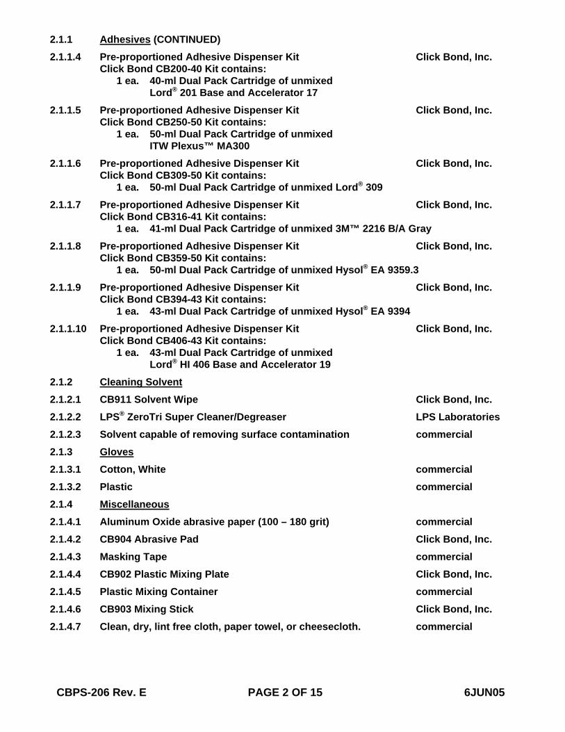
2.2 Equipment 2.2.1 Scale commercial 2.2.2 Spatula commercial 2.2.3 Manual Dispensing Tool, CB100 Click Bond, Inc. 2.2.4 Pneumatic Powered Dispensing Tool, CB110 Click Bond, Inc. 2.2.5 Pneumatic Powered Dispensing Tool, CB112 Click Bond, Inc. 2.2.6 Static Mixer Dispensing Tip, CB106 Click Bond, Inc. 2.2.7 Manual Flaring Tool, CB750 Click Bond, Inc. 2.3 Process Flowchart – Processing shall be as shown in Figure 1.
STANDARD PROCEDURE
1. SOLVENT CLEAN 2. ABRADE (see section 2.4.2) 3. SOLVENT CLEAN 4. MIX AND APPLY ADHESIVE 5. ASSEMBLE PARTS 6. CURE 7. TOUCH UP FINISH
WET ABRASION PROCEDURE
1. WET AREA 2. ABRADE (see section 2.4.4.2) 3. RE-WET 4. WIPE 5. MIX AND APPLY ADHESIVE 6. ASSEMBLE PARTS 7. CURE 8. TOUCH UP FINISH
FIGURE 1. PROCESS FLOWCHART
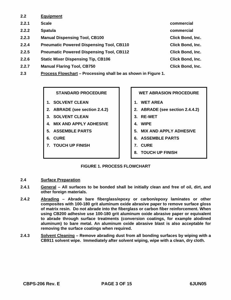
2.4 Surface Preparation 2.4.1 General – All surfaces to be bonded shall be initially clean and free of oil, dirt, and
other foreign materials. 2.4.2 Abrading – Abrade bare fiberglass/epoxy or carbon/epoxy laminates or other
composites with 100-180 grit aluminum oxide abrasive paper to remove surface gloss of matrix resin. Do not abrade into the fiberglass or carbon fiber reinforcement. When using CB200 adhesive use 100-180 grit aluminum oxide abrasive paper or equivalent to abrade through surface treatments (conversion coatings, for example alodined aluminum) to bare metal. An aluminum oxide abrasive blast is also acceptable for removing the surface coatings when required.
2.4.3 Solvent Cleaning – Remove abrading dust from all bonding surfaces by wiping with a CB911 solvent wipe. Immediately after solvent wiping, wipe with a clean, dry cloth.
CBPS-206 Rev. E PAGE 3 OF 15 6JUN05
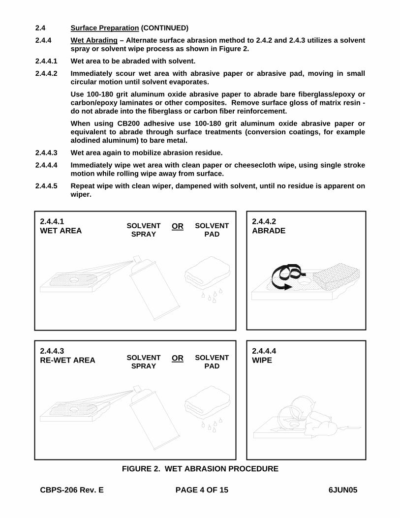
2.4 Surface Preparation (CONTINUED) 2.4.4 Wet Abrading – Alternate surface abrasion method to 2.4.2 and 2.4.3 utilizes a solvent
spray or solvent wipe process as shown in Figure 2. 2.4.4.1 Wet area to be abraded with solvent. 2.4.4.2 Immediately scour wet area with abrasive paper or abrasive pad, moving in small
circular motion until solvent evaporates. Use 100-180 grit aluminum oxide abrasive paper to abrade bare fiberglass/epoxy or carbon/epoxy laminates or other composites. Remove surface gloss of matrix resin -do not abrade into the fiberglass or carbon fiber reinforcement. When using CB200 adhesive use 100-180 grit aluminum oxide abrasive paper or equivalent to abrade through surface treatments (conversion coatings, for example alodined aluminum) to bare metal.
2.4.4.3 Wet area again to mobilize abrasion residue. 2.4.4.4 Immediately wipe wet area with clean paper or cheesecloth wipe, using single stroke
motion while rolling wipe away from surface. 2.4.4.5 Repeat wipe with clean wiper, dampened with solvent, until no residue is apparent on
wiper.
CBPS-206 Rev. E PAGE 4 OF 15 6JUN05
FIGURE 2. WET ABRASION PROCEDURE
2.4.4.4WIPE
2.4.4.2 ABRADE
2.4.4.1 WET AREA
2.4.4.3 RE-WET AREA
SOLVENT SPRAY
SOLVENTPAD
OR
SOLVENT SPRAY
SOLVENTPAD
OR
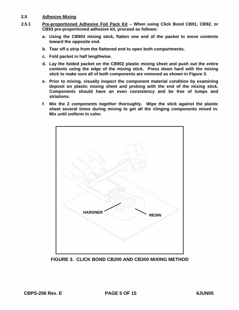
2.5 Adhesive Mixing 2.5.1 Pre-proportioned Adhesive Foil Pack Kit – When using Click Bond CB91, CB92, or
CB93 pre-proportioned adhesive kit, proceed as follows: a. Using the CB903 mixing stick, flatten one end of the packet to move contents
toward the opposite end. b. Tear off a strip from the flattened end to open both compartments. c. Fold packet in half lengthwise. d. Lay the folded packet on the CB902 plastic mixing sheet and push out the entire
contents using the edge of the mixing stick. Press down hard with the mixing stick to make sure all of both components are removed as shown in Figure 3.
e. Prior to mixing, visually inspect the component material condition by examining deposit on plastic mixing sheet and probing with the end of the mixing stick. Components should have an even consistency and be free of lumps and striations.
f. Mix the 2 components together thoroughly. Wipe the stick against the plastic sheet several times during mixing to get all the clinging components mixed in. Mix until uniform in color.
CBPS-206 Rev. E PAGE 5 OF 15 6JUN05
FIGURE 3. CLICK BOND CB200 AND CB300 MIXING METHOD
HARDNERRESIN
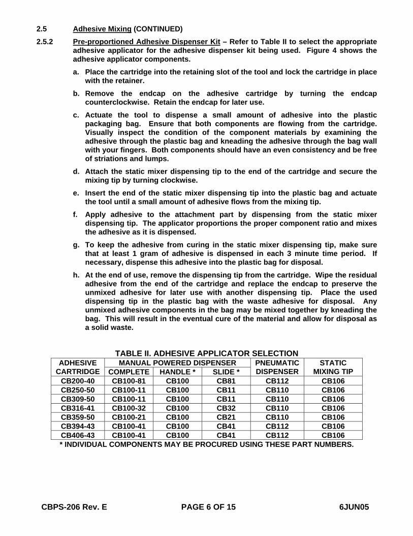
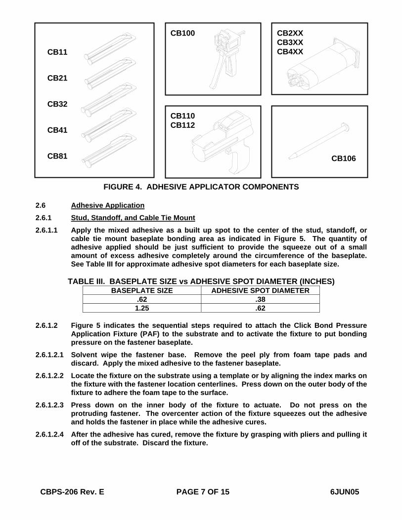
2.5 Adhesive Mixing (CONTINUED) 2.5.2 Pre-proportioned Adhesive Dispenser Kit – Refer to Table II to select the appropriate
adhesive applicator for the adhesive dispenser kit being used. Figure 4 shows the adhesive applicator components. a. Place the cartridge into the retaining slot of the tool and lock the cartridge in place
with the retainer. b. Remove the endcap on the adhesive cartridge by turning the endcap
counterclockwise. Retain the endcap for later use. c. Actuate the tool to dispense a small amount of adhesive into the plastic
packaging bag. Ensure that both components are flowing from the cartridge. Visually inspect the condition of the component materials by examining the adhesive through the plastic bag and kneading the adhesive through the bag wall with your fingers. Both components should have an even consistency and be free of striations and lumps.
d. Attach the static mixer dispensing tip to the end of the cartridge and secure the mixing tip by turning clockwise.
e. Insert the end of the static mixer dispensing tip into the plastic bag and actuate the tool until a small amount of adhesive flows from the mixing tip.
f. Apply adhesive to the attachment part by dispensing from the static mixer dispensing tip. The applicator proportions the proper component ratio and mixes the adhesive as it is dispensed.
g. To keep the adhesive from curing in the static mixer dispensing tip, make sure that at least 1 gram of adhesive is dispensed in each 3 minute time period. If necessary, dispense this adhesive into the plastic bag for disposal.
h. At the end of use, remove the dispensing tip from the cartridge. Wipe the residual adhesive from the end of the cartridge and replace the endcap to preserve the unmixed adhesive for later use with another dispensing tip. Place the used dispensing tip in the plastic bag with the waste adhesive for disposal. Any unmixed adhesive components in the bag may be mixed together by kneading the bag. This will result in the eventual cure of the material and allow for disposal as a solid waste.
TABLE II. ADHESIVE APPLICATOR SELECTION MANUAL POWERED DISPENSER ADHESIVE
CARTRIDGE COMPLETE HANDLE * SLIDE * PNEUMATIC DISPENSER
STATIC MIXING TIP
CB200-40 CB100-81 CB100 CB81 CB112 CB106 CB250-50 CB100-11 CB100 CB11 CB110 CB106 CB309-50 CB100-11 CB100 CB11 CB110 CB106 CB316-41 CB100-32 CB100 CB32 CB110 CB106 CB359-50 CB100-21 CB100 CB21 CB110 CB106 CB394-43 CB100-41 CB100 CB41 CB112 CB106 CB406-43 CB100-41 CB100 CB41 CB112 CB106 * INDIVIDUAL COMPONENTS MAY BE PROCURED USING THESE PART NUMBERS.
CBPS-206 Rev. E PAGE 6 OF 15 6JUN05
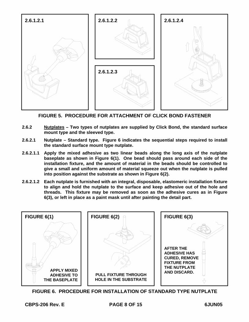
2.6 Adhesive Application 2.6.1 Stud, Standoff, and Cable Tie Mount 2.6.1.1 Apply the mixed adhesive as a built up spot to the center of the stud, standoff, or
cable tie mount baseplate bonding area as indicated in Figure 5. The quantity of adhesive applied should be just sufficient to provide the squeeze out of a small amount of excess adhesive completely around the circumference of the baseplate. See Table III for approximate adhesive spot diameters for each baseplate size.
TABLE III. BASEPLATE SIZE vs ADHESIVE SPOT DIAMETER (INCHES)
BASEPLATE SIZE ADHESIVE SPOT DIAMETER .62 .38
1.25 .62 2.6.1.2 Figure 5 indicates the sequential steps required to attach the Click Bond Pressure
Application Fixture (PAF) to the substrate and to activate the fixture to put bonding pressure on the fastener baseplate.
2.6.1.2.1 Solvent wipe the fastener base. Remove the peel ply from foam tape pads and discard. Apply the mixed adhesive to the fastener baseplate.
2.6.1.2.2 Locate the fixture on the substrate using a template or by aligning the index marks on the fixture with the fastener location centerlines. Press down on the outer body of the fixture to adhere the foam tape to the surface.
2.6.1.2.3 Press down on the inner body of the fixture to actuate. Do not press on the protruding fastener. The overcenter action of the fixture squeezes out the adhesive and holds the fastener in place while the adhesive cures.
2.6.1.2.4 After the adhesive has cured, remove the fixture by grasping with pliers and pulling it off of the substrate. Discard the fixture.
CBPS-206 Rev. E PAGE 7 OF 15 6JUN05
FIGURE 4. ADHESIVE APPLICATOR COMPONENTS
CB11
CB21
CB32
CB41
CB81
CB100
CB110CB112
CB2XX CB3XX CB4XX
CB106
2.6.2 Nutplates – Two types of nutplates are supplied by Click Bond, the standard surface mount type and the sleeved type.
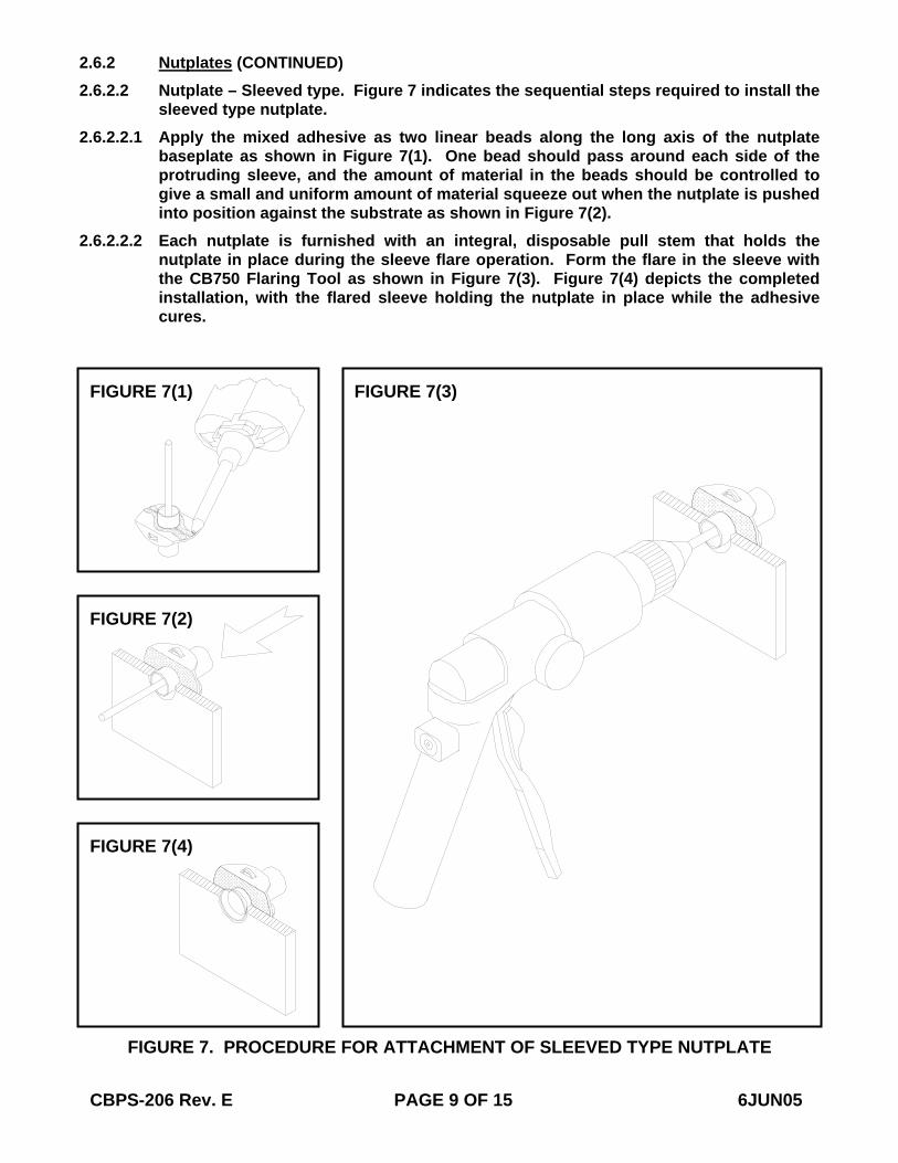
2.6.2.1 Nutplate – Standard type. Figure 6 indicates the sequential steps required to installthe standard surface mount type nutplate.
2.6.2.1.1 Apply the mixed adhesive as two linear beads along the long axis of the nutplate baseplate as shown in Figure 6(1). One bead should pass around each side of the installation fixture, and the amount of material in the beads should be controlled to give a small and uniform amount of material squeeze out when the nutplate is pulled into position against the substrate as shown in Figure 6(2).
2.6.2.1.2 Each nutplate is furnished with an integral, disposable, elastomeric installation fixture to align and hold the nutplate to the surface and keep adhesive out of the hole and threads. This fixture may be removed as soon as the adhesive cures as in Figure 6(3), or left in place as a paint mask until after painting the detail part.
CBPS-206 Rev. E PAGE 8 OF 15 6JUN05
FIGURE 5. PROCEDURE FOR ATTACHMENT OF CLICK BOND FASTENER
2.6.1.2.1 2.6.1.2.2
2.6.1.2.3
2.6.1.2.4
FIGURE 6. PROCEDURE FOR INSTALLATION OF STANDARD TYPE NUTPLATE
FIGURE 6(1) FIGURE 6(2) FIGURE 6(3)
APPLY MIXED ADHESIVE TO
THE BASEPLATE PULL FIXTURE THROUGH HOLE IN THE SUBSTRATE
AFTER THE ADHESIVE HAS CURED, REMOVE FIXTURE FROM THE NUTPLATE AND DISCARD.
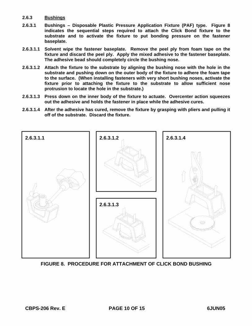
2.6.2 Nutplates (CONTINUED) 2.6.2.2 Nutplate – Sleeved type. Figure 7 indicates the sequential steps required to install the
sleeved type nutplate. 2.6.2.2.1 Apply the mixed adhesive as two linear beads along the long axis of the nutplate
baseplate as shown in Figure 7(1). One bead should pass around each side of the protruding sleeve, and the amount of material in the beads should be controlled to give a small and uniform amount of material squeeze out when the nutplate is pushed into position against the substrate as shown in Figure 7(2).
2.6.2.2.2 Each nutplate is furnished with an integral, disposable pull stem that holds the nutplate in place during the sleeve flare operation. Form the flare in the sleeve with the CB750 Flaring Tool as shown in Figure 7(3). Figure 7(4) depicts the completed installation, with the flared sleeve holding the nutplate in place while the adhesive cures.
CBPS-206 Rev. E PAGE 9 OF 15 6JUN05
FIGURE 7. PROCEDURE FOR ATTACHMENT OF SLEEVED TYPE NUTPLATE
FIGURE 7(1)
FIGURE 7(2)
FIGURE 7(4)
FIGURE 7(3)
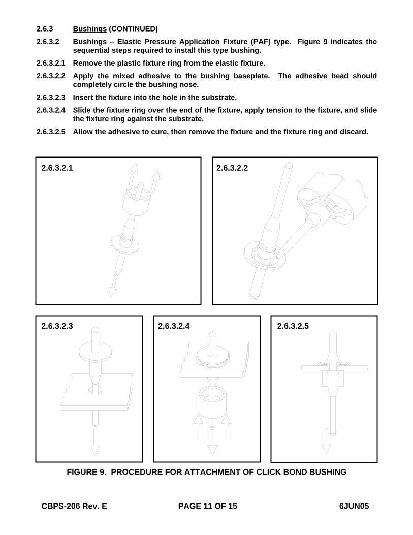
2.6.3 Bushings 2.6.3.1 Bushings – Disposable Plastic Pressure Application Fixture (PAF) type. Figure 8
indicates the sequential steps required to attach the Click Bond fixture to the substrate and to activate the fixture to put bonding pressure on the fastener baseplate.
2.6.3.1.1 Solvent wipe the fastener baseplate. Remove the peel ply from foam tape on the fixture and discard the peel ply. Apply the mixed adhesive to the fastener baseplate. The adhesive bead should completely circle the bushing nose.
2.6.3.1.2 Attach the fixture to the substrate by aligning the bushing nose with the hole in the substrate and pushing down on the outer body of the fixture to adhere the foam tape to the surface. (When installing fasteners with very short bushing noses, activate the fixture prior to attaching the fixture to the substrate to allow sufficient nose protrusion to locate the hole in the substrate.)
2.6.3.1.3 Press down on the inner body of the fixture to actuate. Overcenter action squeezes out the adhesive and holds the fastener in place while the adhesive cures.
2.6.3.1.4 After the adhesive has cured, remove the fixture by grasping with pliers and pulling it off of the substrate. Discard the fixture.
CBPS-206 Rev. E PAGE 10 OF 15 6JUN05
FIGURE 8. PROCEDURE FOR ATTACHMENT OF CLICK BOND BUSHING
2.6.3.1.1 2.6.3.1.2 2.6.3.1.4
2.6.3.1.3
2.6.3 Bushings (CONTINUED) 2.6.3.2 Bushings – Elastic Pressure Application Fixture (PAF) type. Figure 9 indicates the
sequential steps required to install this type bushing. 2.6.3.2.1 Remove the plastic fixture ring from the elastic fixture. 2.6.3.2.2 Apply the mixed adhesive to the bushing baseplate. The adhesive bead should
completely circle the bushing nose. 2.6.3.2.3 Insert the fixture into the hole in the substrate. 2.6.3.2.4 Slide the fixture ring over the end of the fixture, apply tension to the fixture, and slide
the fixture ring against the substrate. 2.6.3.2.5 Allow the adhesive to cure, then remove the fixture and the fixture ring and discard.
CBPS-206 Rev. E PAGE 11 OF 15 6JUN05
FIGURE 9. PROCEDURE FOR ATTACHMENT OF CLICK BOND BUSHING
2.6.3.2.1 2.6.3.2.2
2.6.3.2.3 2.6.3.2.4 2.6.3.2.5
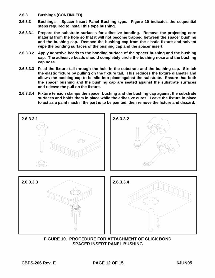
2.6.3 Bushings (CONTINUED) 2.6.3.3 Bushings – Spacer Insert Panel Bushing type. Figure 10 indicates the sequential
steps required to install this type bushing. 2.6.3.3.1 Prepare the substrate surfaces for adhesive bonding. Remove the projecting core
material from the hole so that it will not become trapped between the spacer bushing and the bushing cap. Remove the bushing cap from the elastic fixture and solvent wipe the bonding surfaces of the bushing cap and the spacer insert.
2.6.3.3.2 Apply adhesive beads to the bonding surface of the spacer bushing and the bushing cap. The adhesive beads should completely circle the bushing nose and the bushing cap nose.
2.6.3.3.3 Feed the fixture tail through the hole in the substrate and the bushing cap. Stretch the elastic fixture by pulling on the fixture tail. This reduces the fixture diameter and allows the bushing cap to be slid into place against the substrate. Ensure that both the spacer bushing and the bushing cap are seated against the substrate surfaces and release the pull on the fixture.
2.6.3.3.4 Fixture tension clamps the spacer bushing and the bushing cap against the substrate surfaces and holds them in place while the adhesive cures. Leave the fixture in place to act as a paint mask if the part is to be painted, then remove the fixture and discard.
CBPS-206 Rev. E PAGE 12 OF 15 6JUN05
FIGURE 10. PROCEDURE FOR ATTACHMENT OF CLICK BOND SPACER INSERT PANEL BUSHING
2.6.3.3.1 2.6.3.3.2
2.6.3.3.3 2.6.3.3.4
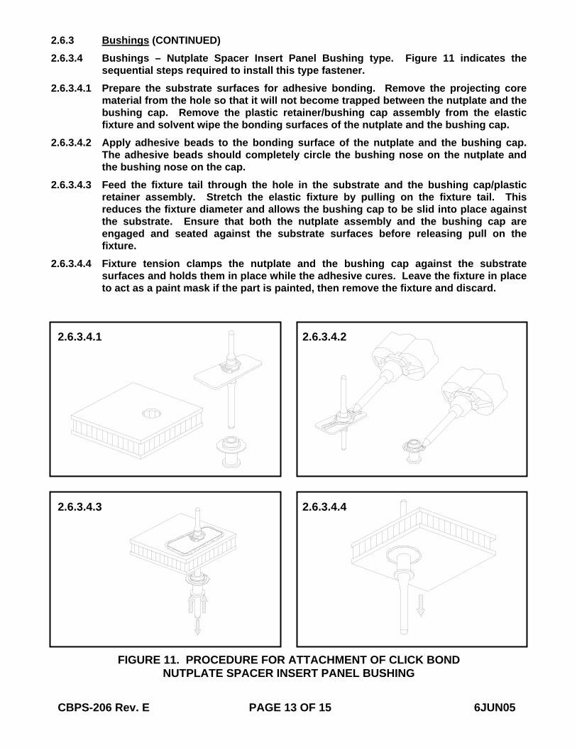
2.6.3 Bushings (CONTINUED) 2.6.3.4 Bushings – Nutplate Spacer Insert Panel Bushing type. Figure 11 indicates the
sequential steps required to install this type fastener. 2.6.3.4.1 Prepare the substrate surfaces for adhesive bonding. Remove the projecting core
material from the hole so that it will not become trapped between the nutplate and the bushing cap. Remove the plastic retainer/bushing cap assembly from the elastic fixture and solvent wipe the bonding surfaces of the nutplate and the bushing cap.
2.6.3.4.2 Apply adhesive beads to the bonding surface of the nutplate and the bushing cap. The adhesive beads should completely circle the bushing nose on the nutplate and the bushing nose on the cap.
2.6.3.4.3 Feed the fixture tail through the hole in the substrate and the bushing cap/plastic retainer assembly. Stretch the elastic fixture by pulling on the fixture tail. This reduces the fixture diameter and allows the bushing cap to be slid into place against the substrate. Ensure that both the nutplate assembly and the bushing cap are engaged and seated against the substrate surfaces before releasing pull on the fixture.
2.6.3.4.4 Fixture tension clamps the nutplate and the bushing cap against the substrate surfaces and holds them in place while the adhesive cures. Leave the fixture in place to act as a paint mask if the part is painted, then remove the fixture and discard.
CBPS-206 Rev. E PAGE 13 OF 15 6JUN05
FIGURE 11. PROCEDURE FOR ATTACHMENT OF CLICK BOND NUTPLATE SPACER INSERT PANEL BUSHING
2.6.3.4.1
2.6.3.4.3
2.6.3.4.2
2.6.3.4.4
2.7 Adhesive Cure – The approximate cure times at 75°F of the adhesives shall be as specified in Table IV. Since the curing rate of all the adhesives is very sensitive to the ambient temperature at the application site, it is recommended that the leftover adhesive in the mixing container or on the mixing sheet be monitored at the application site before removing and discarding the fastener holding fixture.
TABLE IV. ADHESIVE CURE TIME TO HANDLING STRENGTH *
MATERIAL DESIGNATION CURE TIME CLICK BOND CB91 (CB200) 2 HOURS CLICK BOND CB92 (CB200) 2 HOURS CLICK BOND CB93 (CB300) 2 HOURS CLICK BOND CB200-40 2 HOURS CLICK BOND CB250-50 2 HOURS CLICK BOND CB309-50 8-16 HOURS CLICK BOND CB316-21 24 HOURS CLICK BOND CB359-50 24 HOURS CLICK BOND CB394-43 24 HOURS CLICK BOND CB406-43 2 HOURS
* HANDLING STRENGTH – CURE EXCEEDS 75% OF ULTIMATE STRENGTH 2.8 Surface Touch Up – After completion of the cure, all surfaces not within the joint that
have had the surface treatment or organic finish removed shall have the same or equivalent treatment or finish reapplied.
2.9 In-Process Removal Procedure for Studs/Nutplates 2.9.1 Refer to CBPS-207 for the procedure to remove Click Bond fasteners. 2.9.2 After removing the fastener, clean off any remaining adhesive and reapply new
fastener in accordance with the applicable procedure. 2.10 Safety and Environmental Compliance 2.10.1 The storage, handling, use, transportation, and disposal of goods, supplies,
materials, articles, items, equipment, machines, tools, parts, components, assemblies, chemicals, and processes referenced herein shall comply with all applicable national/international, federal, state, and local health, safety, and environmental laws, ordinances, rules, regulations, and codes.
CBPS-206 Rev. E PAGE 14 OF 15 6JUN05
CBPS-206 Rev. E PAGE 15 OF 15 6JUN05
3. QUALITY ASSURANCE PROVISIONS 3.1 Visual Examination 3.1.1 Visual examination of the adhesive components in the containers shall indicate the
material has not gelled, become hard, or settled out to the point where agitation will not restore it to a homogeneous mixture.
3.1.2 Visual examination of the adhesive components as they are dispensed from the pre-proportioned adhesive kits at the point of use shall indicate that the material has not gelled, become hard, or settled out. The consistency of the material shall be tested manually as described in 2.5.1e or 2.5.2c to ensure that it is suitable for application.
3.1.3 All exposed edges of bonded parts shall show a continuous adhesive bead squeeze out along the joined surfaces.
3.1.4 Excess adhesive squeezed out of the joint shall be tested with a fingernail for cure. The adhesive shall feel tough and offer resistance to penetration and shall not be tacky.


![Mechanics of Materials(Best BOOK)[1]](https://img.pdfslide.us/doc/110x75/55cf9bf9550346d033a81427/mechanics-of-materialsbest-book1.jpg)