Embed Size (px)
Citation preview
03/11/2015
1
PMC PROCESSING
MATERIAL KOMPOSIT
PERTEMUAN KE-10
PMC Processing
1. Forming Processes for Thermosetting matrix composites:
� Hand layup and sprayup techniques.
� Filament winding.
� Pultrusion.
� Resin transfer moulding.
� Autoclave moulding.
2. Forming Processes for Thermoplastic matrix composites:
� Injection moulding.
� Film stacking.
� Diaphragm forming.
� Thermoplastic tape laying.
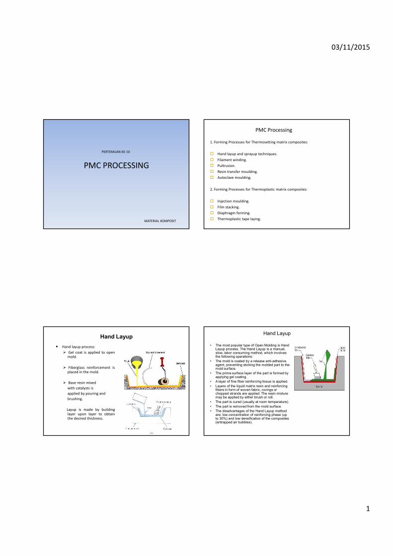
Hand Layup
• Hand layup process:
� Gel coat is applied to openmold.
� Fiberglass reinforcement isplaced in the mold.
� Base resin mixed
with catalysts is
applied by pouring and
brushing.
Layup is made by buildinglayer upon layer to obtainthe desired thickness.
Hand Layup
• The most popular type of Open Molding is Hand Layup process. The Hand Layup is a manual, slow, labor consuming method, which involves the following operations:
• The mold is coated by a release anti-adhesive agent, preventing sticking the molded part to the mold surface.
• The prime surface layer of the part is formed by applying gel coating.
• A layer of fine fiber reinforcing tissue is applied.
• Layers of the liquid matrix resin and reinforcing fibers in form of woven fabric, rovings or chopped strands are applied. The resin mixture may be applied by either brush or roll.
• The part is cured (usually at room temperature).
• The part is removed from the mold surface.
• The disadvantages of the Hand Layup method are: low concentration of reinforcing phase (up to 30%) and low densification of the composites (entrapped air bubbles).
03/11/2015
2
Hand Layup
Advantages:
� Widely used.
� Low tooling cost.
� Custom shape.
� Larger and complex items can
be produced.
Potential Problems:
� Labour intensive.
� Low-volume process.
� Styrene emission.
� Quality control is entirely
dependent on the skill of
labourers.
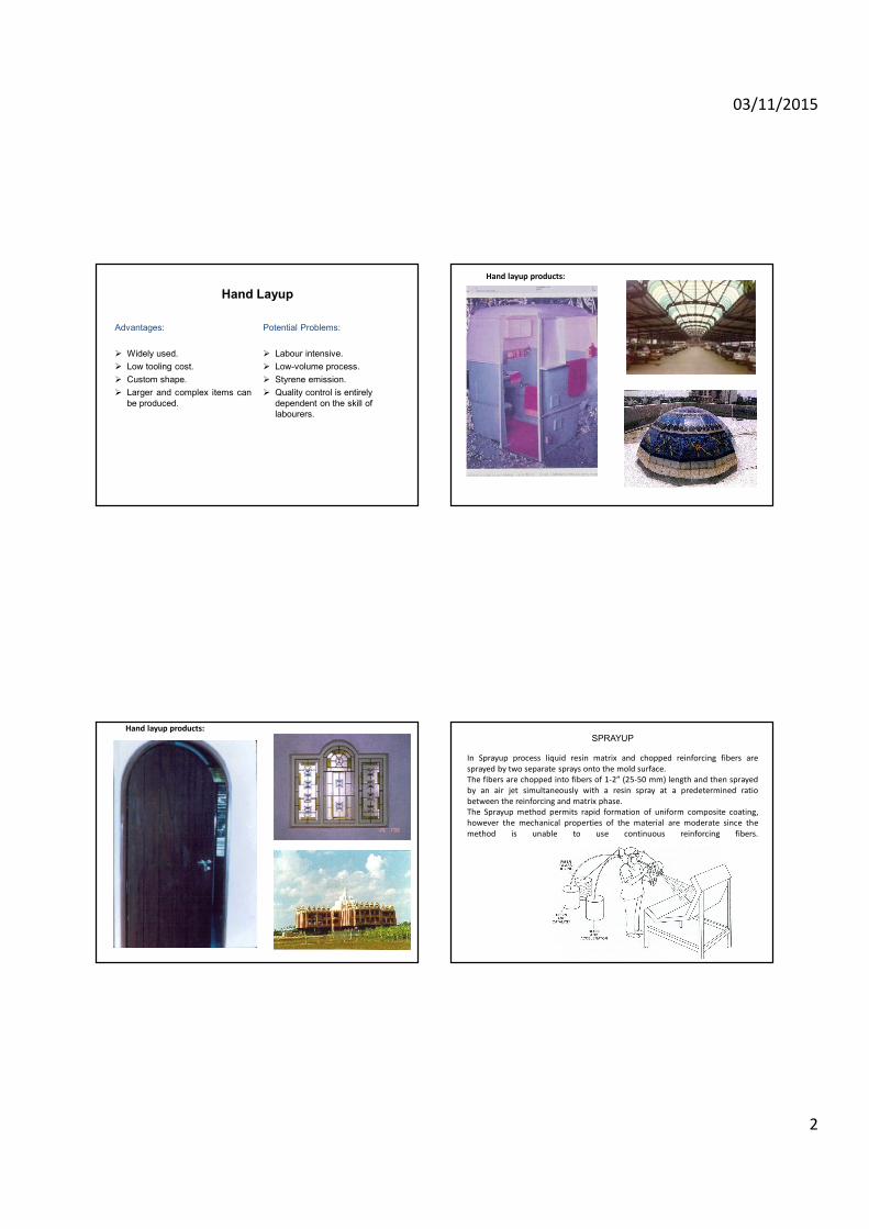
Hand layup products:
Hand layup products:
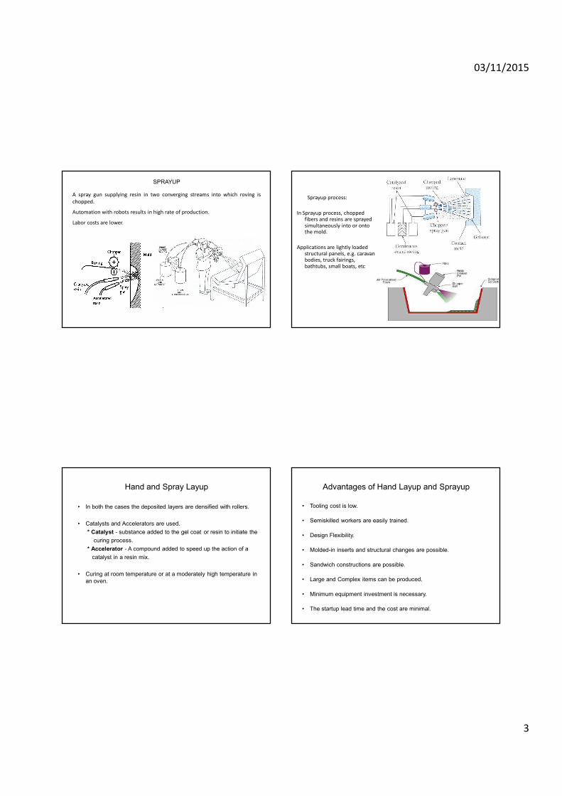
In Sprayup process liquid resin matrix and chopped reinforcing fibers are
sprayed by two separate sprays onto the mold surface.
The fibers are chopped into fibers of 1-2” (25-50 mm) length and then sprayed
by an air jet simultaneously with a resin spray at a predetermined ratio
between the reinforcing and matrix phase.
The Sprayup method permits rapid formation of uniform composite coating,
however the mechanical properties of the material are moderate since the
method is unable to use continuous reinforcing fibers.
SPRAYUP
03/11/2015
3
A spray gun supplying resin in two converging streams into which roving is
chopped.
Automation with robots results in high rate of production.
Labor costs are lower.
SPRAYUP
Sprayup process:
In Sprayup process, chopped fibers and resins are sprayed simultaneously into or onto the mold.
Applications are lightly loaded structural panels, e.g. caravan bodies, truck fairings, bathtubs, small boats, etc
Hand and Spray Layup
• In both the cases the deposited layers are densified with rollers.
• Catalysts and Accelerators are used.
* Catalyst - substance added to the gel coat or resin to initiate the
curing process.
* Accelerator - A compound added to speed up the action of a
catalyst in a resin mix.
• Curing at room temperature or at a moderately high temperature in
an oven.
Advantages of Hand Layup and Sprayup
• Tooling cost is low.
• Semiskilled workers are easily trained.
• Design Flexibility.
• Molded-in inserts and structural changes are possible.
• Sandwich constructions are possible.
• Large and Complex items can be produced.
• Minimum equipment investment is necessary.
• The startup lead time and the cost are minimal.
03/11/2015
4
Disadvantages of Hand Layup and Sprayup
• Labor Intensive.
• Low volume process.
• Longer curing times.
• Production uniformity is difficult.
• Waste factor is high.
PREPREG
٠ Prepreg is the composite
industry’s term for continuous
fiber reinforcement .Pre-
impregnated with a polymer
resin that is only partially
cured.
٠ Prepreg is delivered in tape
form to the manufacturer who
then molds and fully cures the
product without having to add
any resin.
٠ This is the composite form
most widely used for structural
applications.
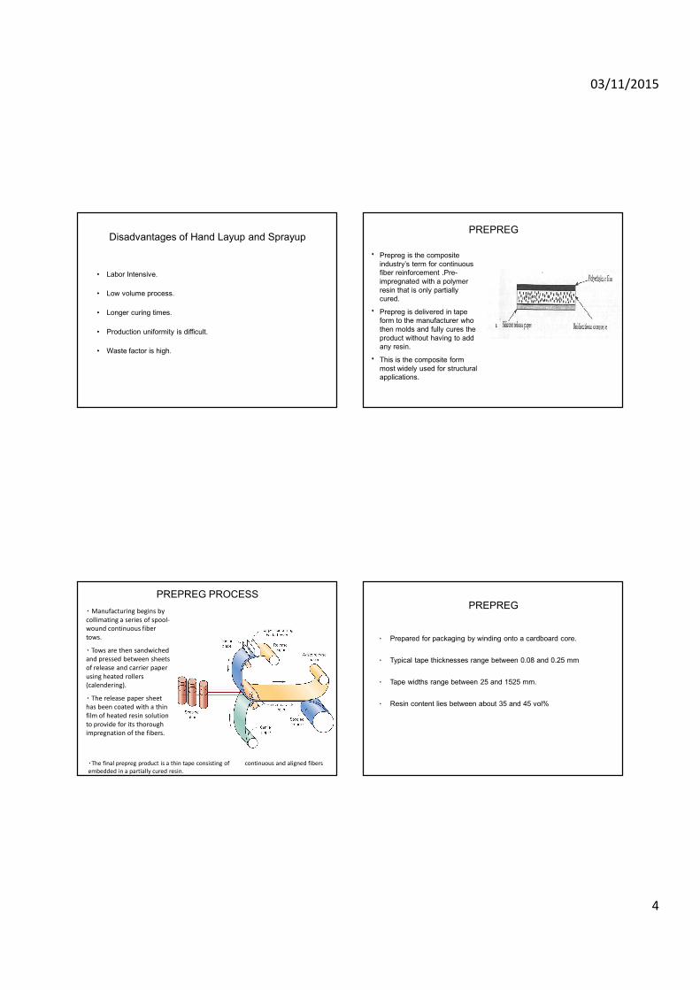
٠Manufacturing begins by
collimating a series of spool-
wound continuous fiber
tows.
٠ Tows are then sandwiched
and pressed between sheets
of release and carrier paper
using heated rollers
(calendering).
٠ The release paper sheet
has been coated with a thin
film of heated resin solution
to provide for its thorough
impregnation of the fibers.
PREPREG PROCESS
٠The final prepreg product is a thin tape consisting of continuous and aligned fibers
embedded in a partially cured resin.
PREPREG
٠ Prepared for packaging by winding onto a cardboard core.
٠ Typical tape thicknesses range between 0.08 and 0.25 mm
٠ Tape widths range between 25 and 1525 mm.
٠ Resin content lies between about 35 and 45 vol%
03/11/2015
5
PREPREG
٠ The prepreg is stored at 0°C (32 °F) or lower because matrix undergoes
curing reactions at room temperature. Also the time in use at room
temperature must be minimized. Life time is about 6 months if
properly handled.
٠ Both thermoplastic and thermosetting resins are utilized: carbon, glass,
and aramid fibers are the common reinforcements.
٠ Actual fabrication begins with the lay-up. Normally a number of plies
are laid up to provide the desired thickness.
٠ The layup can be by hand or automated.
٠
Easily obtained with epoxies.
18
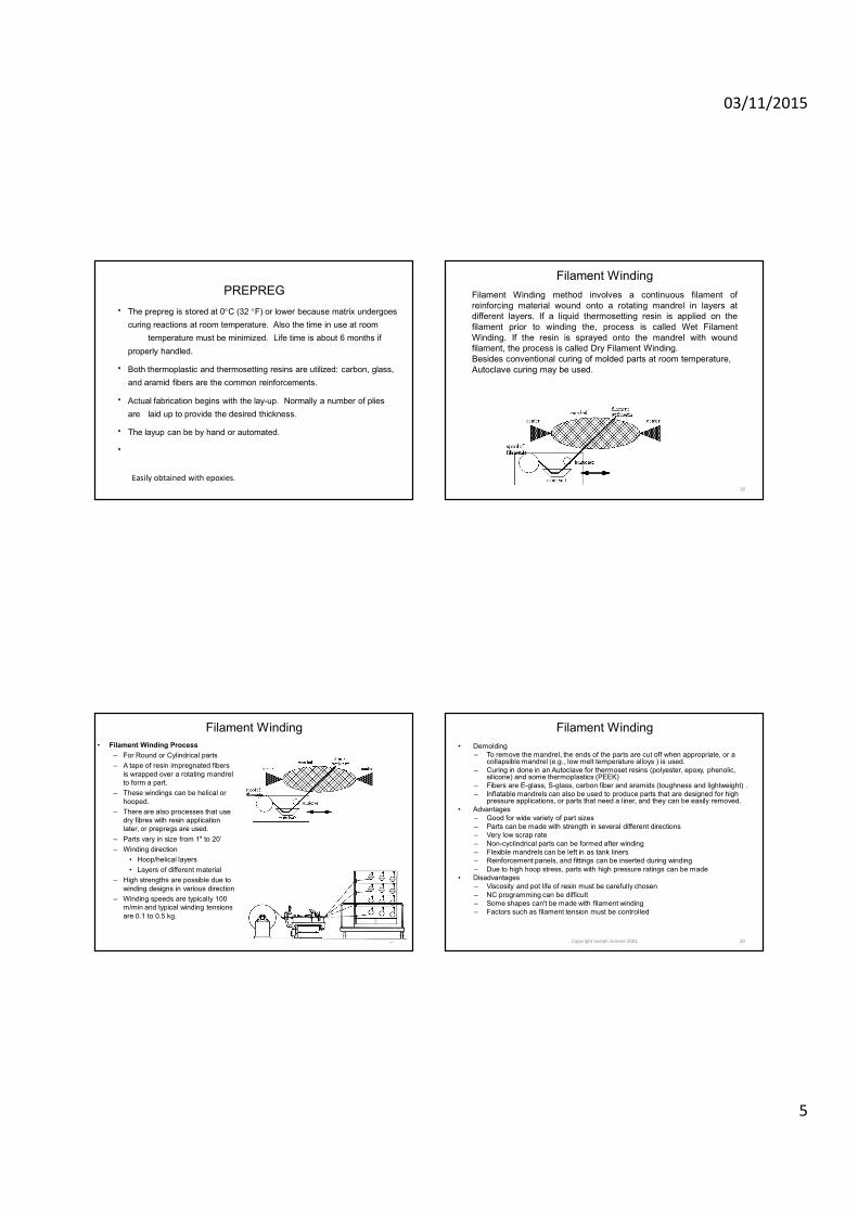
Filament Winding
Filament Winding method involves a continuous filament of
reinforcing material wound onto a rotating mandrel in layers at
different layers. If a liquid thermosetting resin is applied on the
filament prior to winding the, process is called Wet Filament
Winding. If the resin is sprayed onto the mandrel with wound
filament, the process is called Dry Filament Winding.
Besides conventional curing of molded parts at room temperature,
Autoclave curing may be used.
19
Filament Winding
• Filament Winding Process
– For Round or Cylindrical parts
– A tape of resin impregnated fibers
is wrapped over a rotating mandrel
to form a part.
– These windings can be helical or
hooped.
– There are also processes that use
dry fibres with resin application
later, or prepregs are used.
– Parts vary in size from 1" to 20’
– Winding direction
• Hoop/helical layers
• Layers of different material
– High strengths are possible due to
winding designs in various direction
– Winding speeds are typically 100
m/min and typical winding tensions
are 0.1 to 0.5 kg.
Copyright Joseph Greene 2001 20
Filament Winding
• Demolding
– To remove the mandrel, the ends of the parts are cut off when appropriate, or a collapsible mandrel (e.g., low melt temperature alloys ) is used.
– Curing in done in an Autoclave for thermoset resins (polyester, epoxy, phenolic, silicone) and some thermoplastics (PEEK)
– Fibers are E-glass, S-glass, carbon fiber and aramids (toughness and lightweight) .
– Inflatable mandrels can also be used to produce parts that are designed for high pressure applications, or parts that need a liner, and they can be easily removed.
• Advantages
– Good for wide variety of part sizes
– Parts can be made with strength in several different directions
– Very low scrap rate
– Non-cyclindrical parts can be formed after winding
– Flexible mandrels can be left in as tank liners
– Reinforcement panels, and fittings can be inserted during winding
– Due to high hoop stress, parts with high pressure ratings can be made
• Disadvantages
– Viscosity and pot life of resin must be carefully chosen
– NC programming can be difficult
– Some shapes can't be made with filament winding
– Factors such as filament tension must be controlled
03/11/2015
6
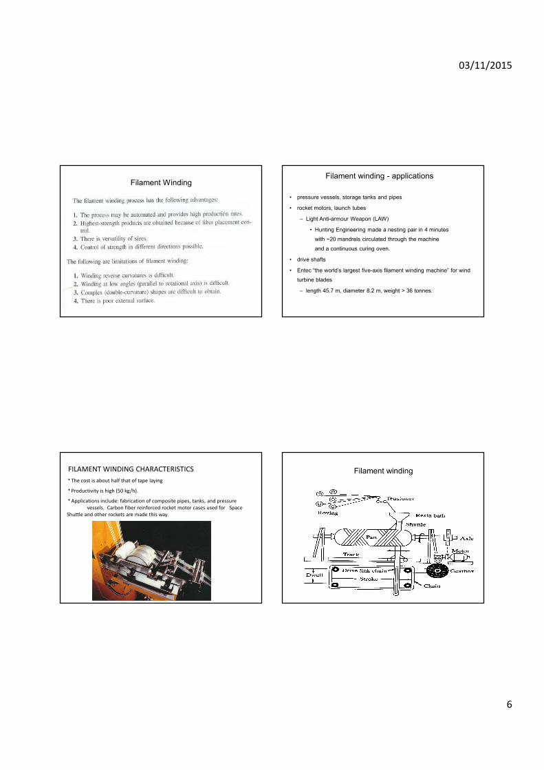
Filament WindingFilament winding - applications
• pressure vessels, storage tanks and pipes
• rocket motors, launch tubes
– Light Anti-armour Weapon (LAW)
• Hunting Engineering made a nesting pair in 4 minutes
with ~20 mandrels circulated through the machine
and a continuous curing oven.
• drive shafts
• Entec “the world’s largest five-axis filament winding machine” for wind
turbine blades
– length 45.7 m, diameter 8.2 m, weight > 36 tonnes.
FILAMENT WINDING CHARACTERISTICS
٠The cost is about half that of tape laying
٠Productivity is high (50 kg/h).
٠Applications include: fabrication of composite pipes, tanks, and pressure
vessels. Carbon fiber reinforced rocket motor cases used for Space
Shuttle and other rockets are made this way.
Filament winding
03/11/2015
7
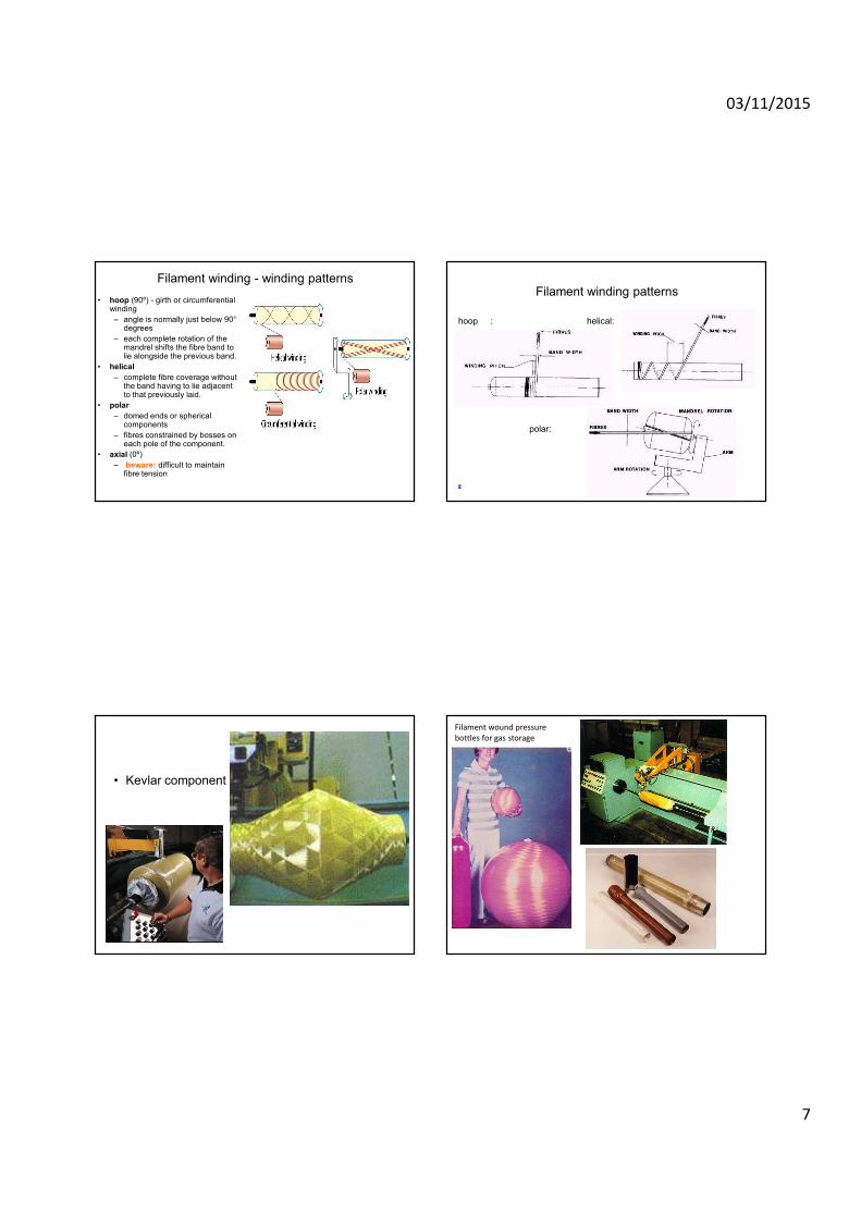
Filament winding - winding patterns
• hoop (90º) - girth or circumferential winding
– angle is normally just below 90°degrees
– each complete rotation of the mandrel shifts the fibre band to lie alongside the previous band.
• helical
– complete fibre coverage without the band having to lie adjacent to that previously laid.
• polar
– domed ends or spherical components
– fibres constrained by bosses on each pole of the component.
• axial (0º)
– beware: difficult to maintain fibre tension
Filament winding patterns
hoop : helical:
polar:
g
• Kevlar component
Filament wound pressure
bottles for gas storage
03/11/2015
8
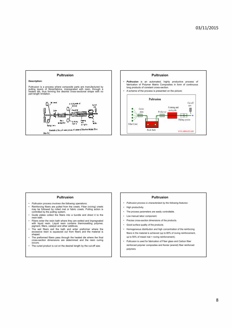
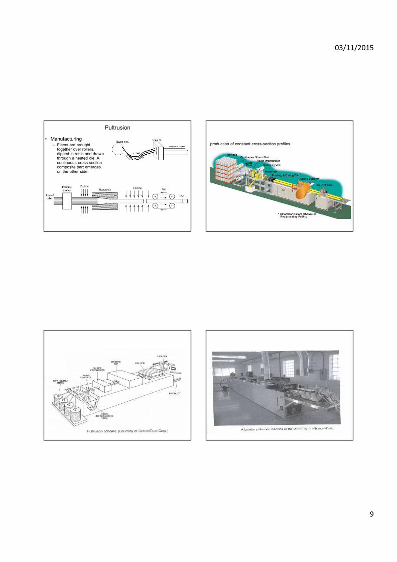
Pultrusion
Description:
Pultrusion is a process where composite parts are manufactured bypulling layers of fibres/fabrics, impregnated with resin, through aheated die, thus forming the desired cross-sectional shape with nopart length limitation.
Pultrusion
• Pultrusion is an automated, highly productive process of
fabrication of Polymer Matrix Composites in form of continuous
long products of constant cross-section.
• A scheme of the process is presented on the picture:
Pultrusion
• Pultrusion process involves the following operations:
• Reinforcing fibers are pulled from the creels. Fiber (roving) creelsmay be followed by rolled mat or fabric creels. Pulling action iscontrolled by the pulling system.
• Guide plates collect the fibers into a bundle and direct it to theresin bath.
• Fibers enter the resin bath where they are wetted and impregnatedwith liquid resin. Liquid resin contains thermosetting polymer,pigment, fillers, catalyst and other additives.
• The wet fibers exit the bath and enter preformer where theexcessive resin is squeezed out from fibers and the material isshaped.
• The preformed fibers pass through the heated die where the finalcross-section dimensions are determined and the resin curingoccurs.
• The cured product is cut on the desired length by the cut-off saw.
Pultrusion
• Pultrusion process is characterized by the following features:
• High productivity.
• The process parameters are easily controllable.
• Low manual labor component.
• Precise cross-section dimensions of the products.
• Good surface quality of the products.
• Homogeneous distribution and high concentration of the reinforcing
fibers in the material is achieved (up to 80% of roving reinforcement,
up to 50% of mixed mat + roving reinforcement).
• Pultrusion is used for fabrication of Fiber glass and Carbon fiber
reinforced polymer composites and Kevlar (aramid) fiber reinforced
polymers.
03/11/2015
9
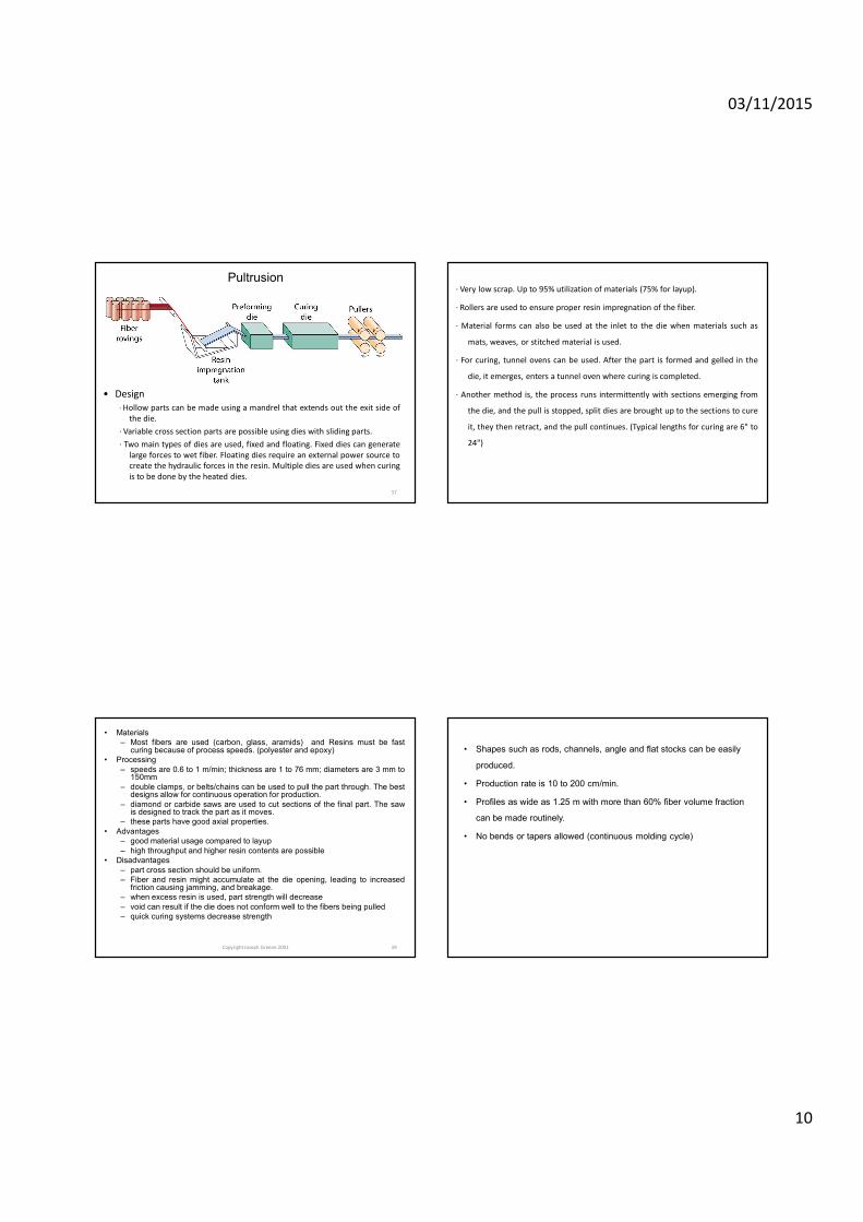
Pultrusion
• Manufacturing– Fibers are brought
together over rollers, dipped in resin and drawn through a heated die. A continuous cross section composite part emerges on the other side.
production of constant cross-section profiles
03/11/2015
10
37
Pultrusion
• Design
· Hollow parts can be made using a mandrel that extends out the exit side of
the die.
· Variable cross section parts are possible using dies with sliding parts.
· Two main types of dies are used, fixed and floating. Fixed dies can generate
large forces to wet fiber. Floating dies require an external power source to
create the hydraulic forces in the resin. Multiple dies are used when curing
is to be done by the heated dies.
· Very low scrap. Up to 95% utilization of materials (75% for layup).
· Rollers are used to ensure proper resin impregnation of the fiber.
· Material forms can also be used at the inlet to the die when materials such as
mats, weaves, or stitched material is used.
· For curing, tunnel ovens can be used. After the part is formed and gelled in the
die, it emerges, enters a tunnel oven where curing is completed.
· Another method is, the process runs intermittently with sections emerging from
the die, and the pull is stopped, split dies are brought up to the sections to cure
it, they then retract, and the pull continues. (Typical lengths for curing are 6" to
24")
Copyright Joseph Greene 2001 39
• Materials
– Most fibers are used (carbon, glass, aramids) and Resins must be fastcuring because of process speeds. (polyester and epoxy)
• Processing
– speeds are 0.6 to 1 m/min; thickness are 1 to 76 mm; diameters are 3 mm to150mm
– double clamps, or belts/chains can be used to pull the part through. The bestdesigns allow for continuous operation for production.
– diamond or carbide saws are used to cut sections of the final part. The sawis designed to track the part as it moves.
– these parts have good axial properties.
• Advantages
– good material usage compared to layup
– high throughput and higher resin contents are possible
• Disadvantages
– part cross section should be uniform.
– Fiber and resin might accumulate at the die opening, leading to increasedfriction causing jamming, and breakage.
– when excess resin is used, part strength will decrease
– void can result if the die does not conform well to the fibers being pulled
– quick curing systems decrease strength
• Shapes such as rods, channels, angle and flat stocks can be easily
produced.
• Production rate is 10 to 200 cm/min.
• Profiles as wide as 1.25 m with more than 60% fiber volume fraction
can be made routinely.
• No bends or tapers allowed (continuous molding cycle)
03/11/2015
11
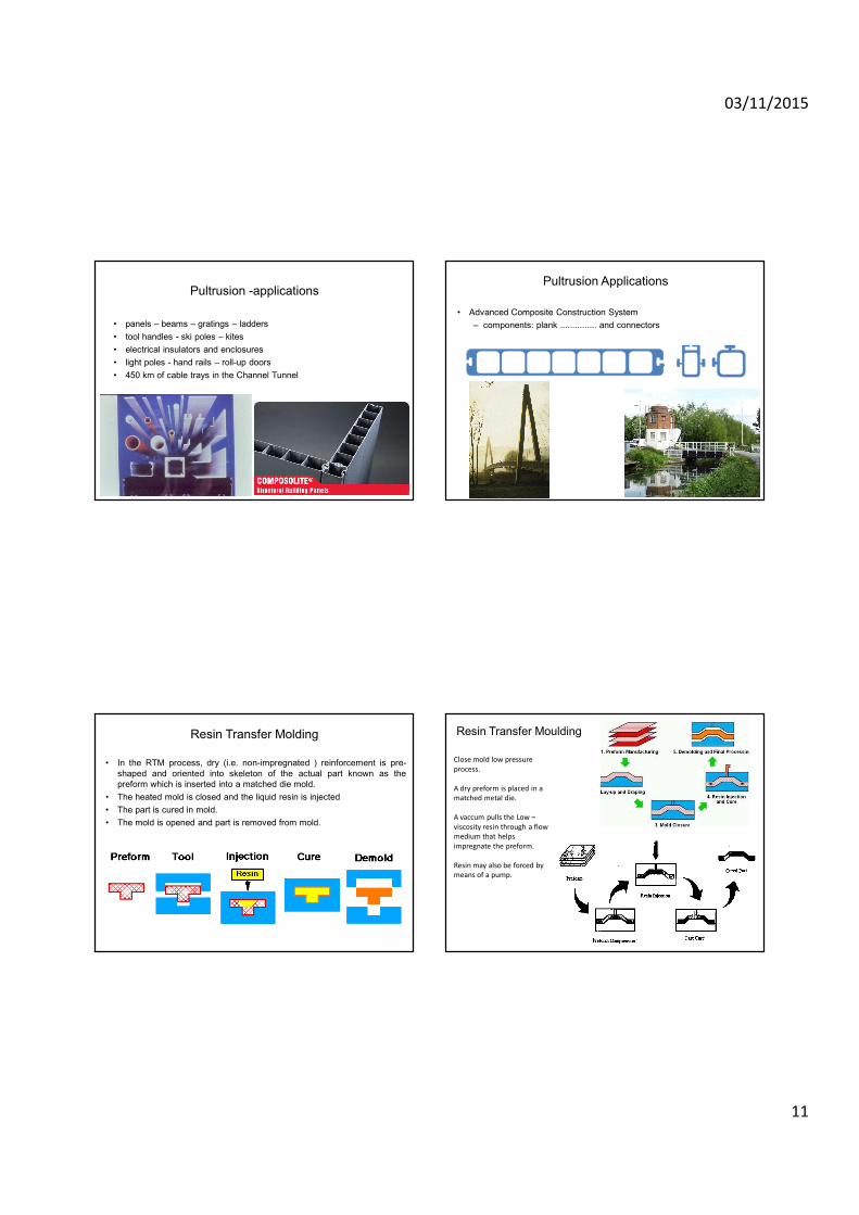
Pultrusion -applications
• panels – beams – gratings – ladders
• tool handles - ski poles – kites
• electrical insulators and enclosures
• light poles - hand rails – roll-up doors
• 450 km of cable trays in the Channel Tunnel
Pultrusion Applications
• Advanced Composite Construction System
– components: plank ............... and connectors
– used in Aberfeldy and Bonds Mill Lock bridges
– http://
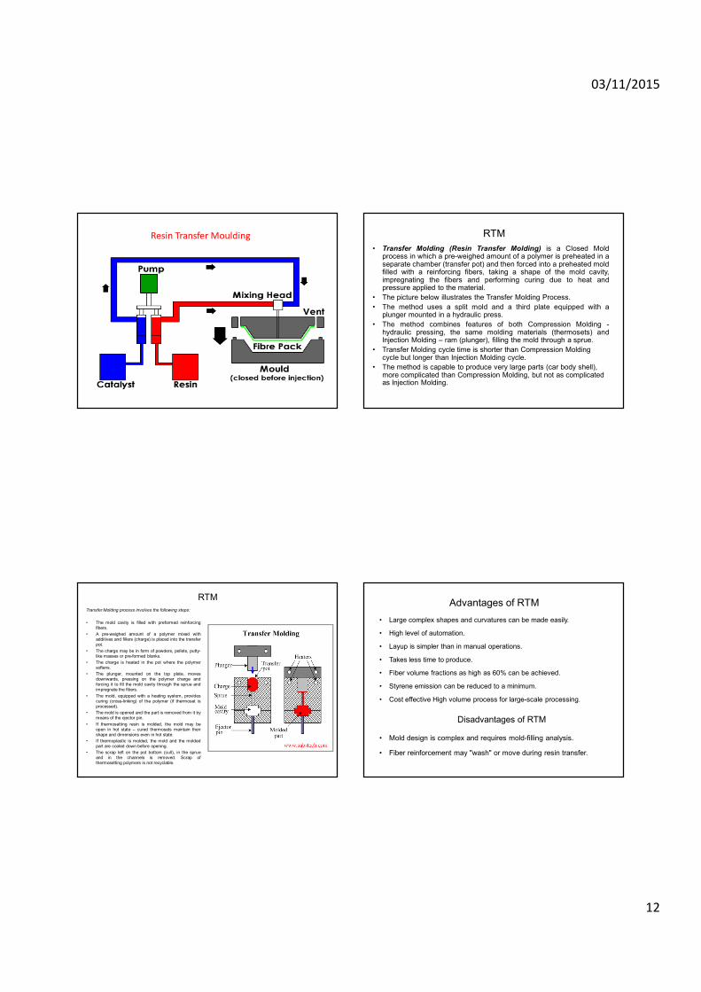
Resin Transfer Molding
• In the RTM process, dry (i.e. non-impregnated ) reinforcement is pre-
shaped and oriented into skeleton of the actual part known as the
preform which is inserted into a matched die mold.
• The heated mold is closed and the liquid resin is injected
• The part is cured in mold.
• The mold is opened and part is removed from mold.
Resin Transfer Moulding
Close mold low pressure
process.
A dry preform is placed in a
matched metal die.
A vaccum pulls the Low –
viscosity resin through a flow
medium that helps
impregnate the preform.
Resin may also be forced by
means of a pump.
03/11/2015
12
Resin Transfer Moulding RTM
• Transfer Molding (Resin Transfer Molding) is a Closed Moldprocess in which a pre-weighed amount of a polymer is preheated in aseparate chamber (transfer pot) and then forced into a preheated moldfilled with a reinforcing fibers, taking a shape of the mold cavity,impregnating the fibers and performing curing due to heat andpressure applied to the material.
• The picture below illustrates the Transfer Molding Process.
• The method uses a split mold and a third plate equipped with aplunger mounted in a hydraulic press.
• The method combines features of both Compression Molding -hydraulic pressing, the same molding materials (thermosets) andInjection Molding – ram (plunger), filling the mold through a sprue.
• Transfer Molding cycle time is shorter than Compression Molding cycle but longer than Injection Molding cycle.
• The method is capable to produce very large parts (car body shell), more complicated than Compression Molding, but not as complicated as Injection Molding.
RTM
Transfer Molding process involves the following steps:
• The mold cavity is filled with preformed reinforcing
fibers.
• A pre-weighed amount of a polymer mixed with
additives and fillers (charge) is placed into the transfer
pot.
• The charge may be in form of powders, pellets, putty-
like masses or pre-formed blanks.
• The charge is heated in the pot where the polymer
softens.
• The plunger, mounted on the top plate, moves
downwards, pressing on the polymer charge and
forcing it to fill the mold cavity through the sprue and
impregnate the fibers.
• The mold, equipped with a heating system, provides
curing (cross-linking) of the polymer (if thermoset is
processed).
• The mold is opened and the part is removed from it by
means of the ejector pin.
• If thermosetting resin is molded, the mold may be
open in hot state – cured thermosets maintain their
shape and dimensions even in hot state.
• If thermoplastic is molded, the mold and the molded
part are cooled down before opening.
• The scrap left on the pot bottom (cull), in the sprue
and in the channels is removed. Scrap of
thermosetting polymers is not recyclable.
Advantages of RTM
• Large complex shapes and curvatures can be made easily.
• High level of automation.
• Layup is simpler than in manual operations.
• Takes less time to produce.
• Fiber volume fractions as high as 60% can be achieved.
• Styrene emission can be reduced to a minimum.
• Cost effective High volume process for large-scale processing.
Disadvantages of RTM
• Mold design is complex and requires mold-filling analysis.
• Fiber reinforcement may "wash" or move during resin transfer.
03/11/2015
13
Resin Transfer Moulding
Advantages:
� Low skill labour required
� Low tooling cost
� Low volatile emission
� Required design tailorability
Potential Problems:
� Control of resin flow
� Kinking of fibres
� Criticality in mould design
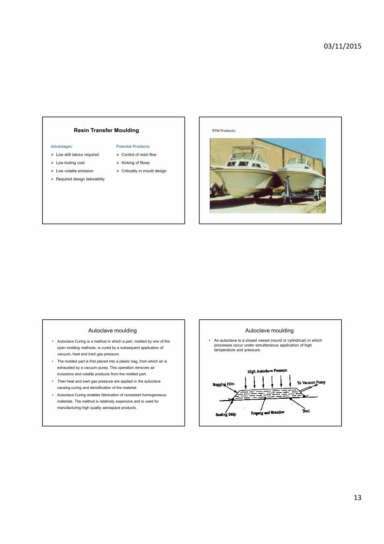
RTM Products:
Autoclave moulding
• Autoclave Curing is a method in which a part, molded by one of the
open molding methods, is cured by a subsequent application of
vacuum, heat and inert gas pressure.
• The molded part is first placed into a plastic bag, from which air is
exhausted by a vacuum pump. This operation removes air
inclusions and volatile products from the molded part.
• Then heat and inert gas pressure are applied in the autoclave
causing curing and densification of the material.
• Autoclave Curing enables fabrication of consistent homogeneous
materials. The method is relatively expensive and is used for
manufacturing high quality aerospace products.
Autoclave moulding
• An autoclave is a closed vessel (round or cylindrical) in which
processes occur under simultaneous application of high
temperature and pressure.
03/11/2015
14
Copyright Joseph Greene 2001 53
Autoclave
• An oven that allows for high pressures to be used.
• Composites cure under heat and pressure provides a superior part because the voids are reduced due to the pressure.
• Process
– The part is placed in the pressure vessel, and heated, pressure is applied simultaneously.
– Vacuum bagging can be used in an autoclave.
– Thermoset composites are crosslinked.
– Thermoplastics are melted.
• Advantages
– The pressure helps bond composite layers, and remove more voids in the matrix.
– Very large parts can be made with high fiber loadings.
– Properties are improved.
– Many different parts can be cured at
the same time.
• Disadvantages
– Autoclaves are expensive
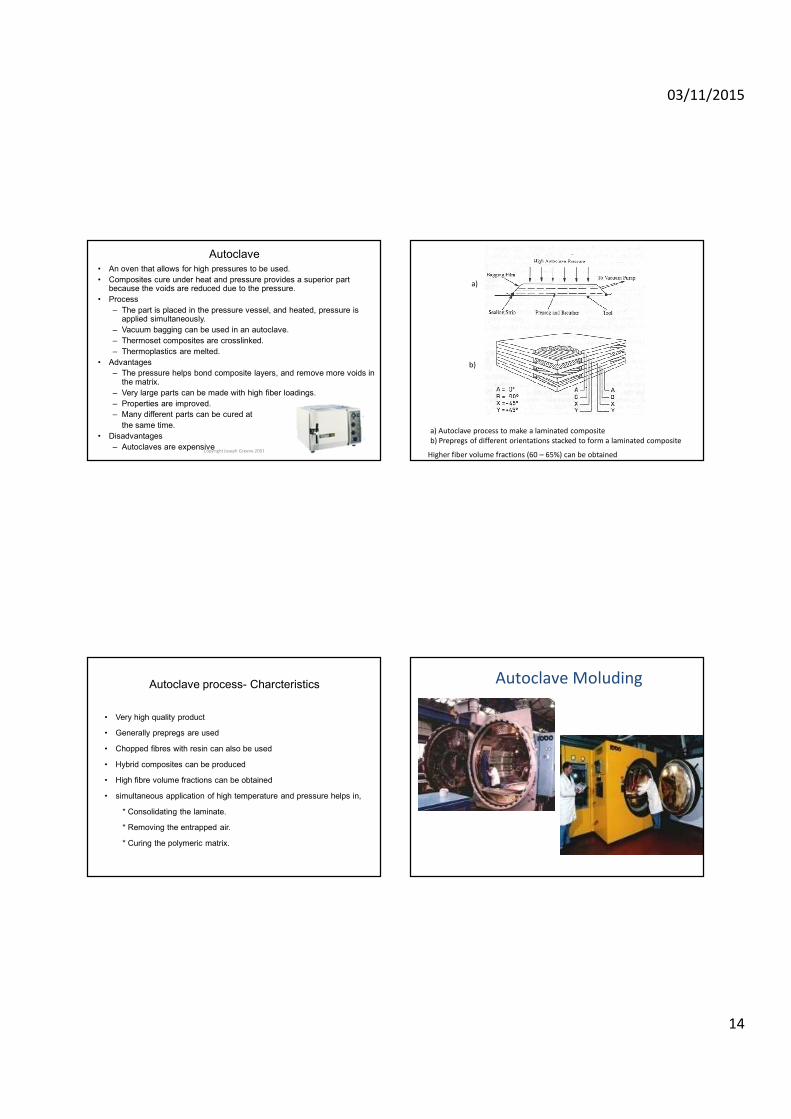
a) Autoclave process to make a laminated composite
b) Prepregs of different orientations stacked to form a laminated composite
a)
b)
Higher fiber volume fractions (60 – 65%) can be obtained
Autoclave process- Charcteristics
• Very high quality product
• Generally prepregs are used
• Chopped fibres with resin can also be used
• Hybrid composites can be produced
• High fibre volume fractions can be obtained
• simultaneous application of high temperature and pressure helps in,
* Consolidating the laminate.
* Removing the entrapped air.
* Curing the polymeric matrix.
Autoclave Moluding
03/11/2015
15
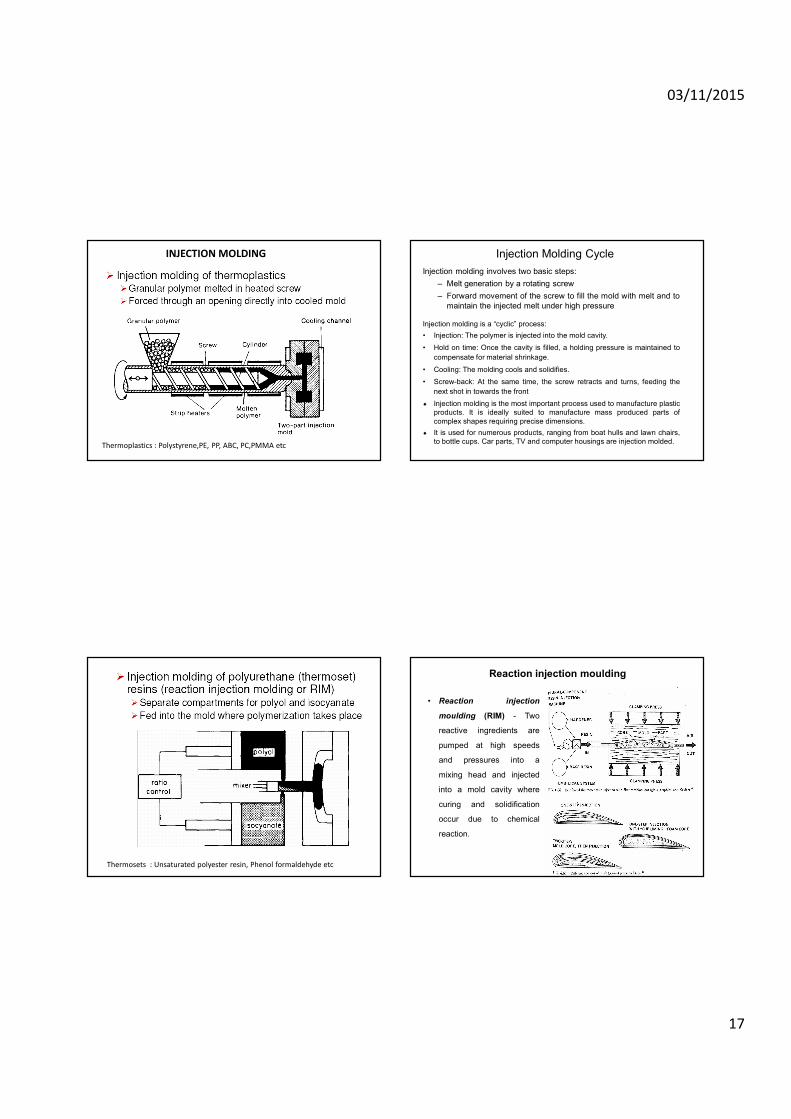
Injection moulding
• Injection Molding is a Closed Mold process in which moltenpolymer (commonly thermoplastic) mixed with very short reinforcingfibers (10-40%) is forced under high pressure into a mold cavitythrough an opening (sprue).
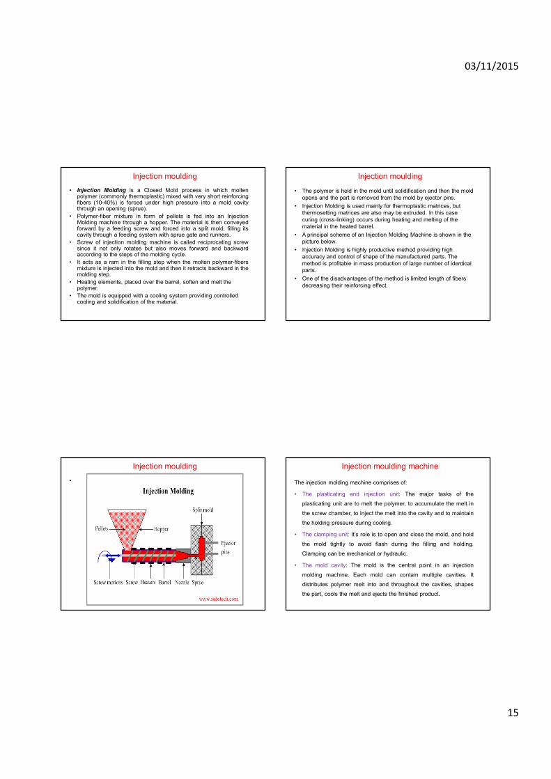
• Polymer-fiber mixture in form of pellets is fed into an InjectionMolding machine through a hopper. The material is then conveyedforward by a feeding screw and forced into a split mold, filling itscavity through a feeding system with sprue gate and runners.
• Screw of injection molding machine is called reciprocating screwsince it not only rotates but also moves forward and backwardaccording to the steps of the molding cycle.
• It acts as a ram in the filling step when the molten polymer-fibersmixture is injected into the mold and then it retracts backward in themolding step.
• Heating elements, placed over the barrel, soften and melt the polymer.
• The mold is equipped with a cooling system providing controlled cooling and solidification of the material.
Injection moulding
• The polymer is held in the mold until solidification and then the mold
opens and the part is removed from the mold by ejector pins.
• Injection Molding is used mainly for thermoplastic matrices, but
thermosetting matrices are also may be extruded. In this case
curing (cross-linking) occurs during heating and melting of the
material in the heated barrel.
• A principal scheme of an Injection Molding Machine is shown in the
picture below.
• Injection Molding is highly productive method providing high
accuracy and control of shape of the manufactured parts. The
method is profitable in mass production of large number of identical
parts.
• One of the disadvantages of the method is limited length of fibers
decreasing their reinforcing effect.
Injection moulding
•
Injection moulding machine
The injection molding machine comprises of:
• The plasticating and injection unit: The major tasks of the
plasticating unit are to melt the polymer, to accumulate the melt in
the screw chamber, to inject the melt into the cavity and to maintain
the holding pressure during cooling.
• The clamping unit: It’s role is to open and close the mold, and hold
the mold tightly to avoid flash during the filling and holding.
Clamping can be mechanical or hydraulic.
• The mold cavity: The mold is the central point in an injection
molding machine. Each mold can contain multiple cavities. It
distributes polymer melt into and throughout the cavities, shapes
the part, cools the melt and ejects the finished product.
03/11/2015
16
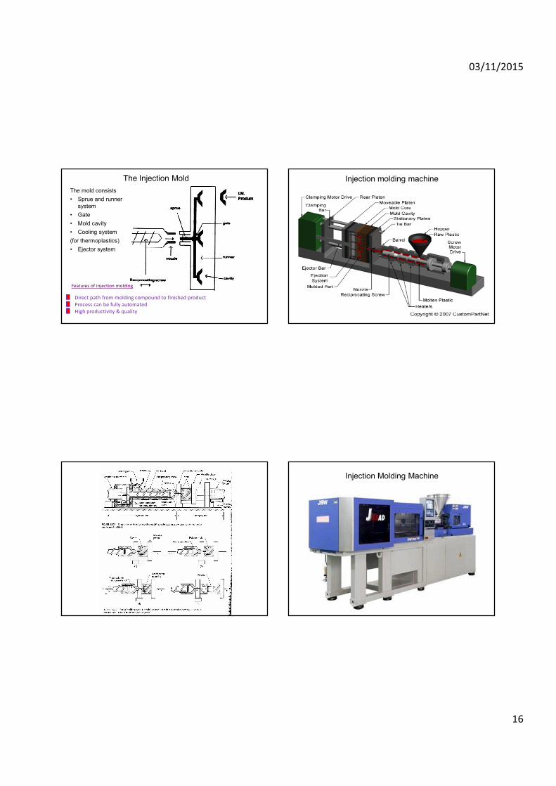
The Injection Mold
The mold consists
• Sprue and runner
system
• Gate
• Mold cavity
• Cooling system
(for thermoplastics)
• Ejector system
Features of injection molding
Direct path from molding compound to finished product
Process can be fully automated
High productivity & quality
Injection molding machine
Injection Molding Machine
03/11/2015
17
INJECTION MOLDING
Thermoplastics : Polystyrene,PE, PP, ABC, PC,PMMA etc
Injection Molding Cycle
Injection molding involves two basic steps:
– Melt generation by a rotating screw
– Forward movement of the screw to fill the mold with melt and to
maintain the injected melt under high pressure
Injection molding is a “cyclic” process:
• Injection: The polymer is injected into the mold cavity.
• Hold on time: Once the cavity is filled, a holding pressure is maintained to
compensate for material shrinkage.
• Cooling: The molding cools and solidifies.
• Screw-back: At the same time, the screw retracts and turns, feeding the
next shot in towards the front
� Injection molding is the most important process used to manufacture plastic
products. It is ideally suited to manufacture mass produced parts of
complex shapes requiring precise dimensions.
� It is used for numerous products, ranging from boat hulls and lawn chairs,
to bottle cups. Car parts, TV and computer housings are injection molded.
Thermosets : Unsaturated polyester resin, Phenol formaldehyde etc
Reaction injection moulding
• Reaction injection
moulding (RIM) - Two
reactive ingredients are
pumped at high speeds
and pressures into a
mixing head and injected
into a mold cavity where
curing and solidification
occur due to chemical
reaction.
03/11/2015
18
Reinforced reaction injection molding
Reinforced reaction injection moulding (RRIM) - similar to RIM but
includes reinforcing fibers, typically glass fibers, in the mixture .
• Advantages: similar to RIM (e.g., no heat energy required, lower
cost mold), with the added benefit of fiber reinforcement.
• Products: auto body, truck cab applications for bumpers, fenders,
and other body parts
Film stacking
• Stack of laminate consists of fibers, impregnated with insufficient
thermoplastic matrix, and polymer films of complementary weight to
give the desired fiber volume fraction in the end product. These are
then consolidated by simultaneous application of heat and pressure.
• Generally, a pressure of 6-12 MPa, a temperature between 275 and
350º C, and dwell times of up to 30 mins are appropriate for
thermoplastics such as polysulfones and polyetheretherketone
(PEEK).
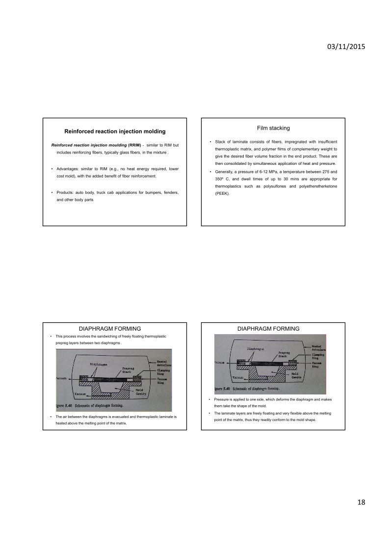
DIAPHRAGM FORMING
• This process involves the sandwiching of freely floating thermoplastic
prepreg layers between two diaphragms .
• The air between the diaphragms is evacuated and thermoplastic laminate is
heated above the melting point of the matrix.
DIAPHRAGM FORMING
• Pressure is applied to one side, which deforms the diaphragm and makes
them take the shape of the mold.
• The laminate layers are freely floating and very flexible above the melting
point of the matrix, thus they readily conform to the mold shape.
03/11/2015
19
DIAPHRAGM FORMING
• After the completion of the forming process, the mold is cooled, the
diaphragms are stripped off, and the composite is obtained.
The diaphragms are the key to the forming process, and their
stiffness is a very critical parameter.
• For very complex shapes requiring high molding pressures, stiff
diaphragm are needed. At high pressures, a significant transverse
squeezing flow can result, and this can produce undesirable
thickness variations in the final composite.
DIAPHRAGM FORMING
ADVANTAGES:
• Components with double curvatures can be formed.
• Compliant diaphragm do the job for simple components.
Thermoplastic tape laying
(Automated Layup)
• In this method layers of prepreg (reinforcing phase impregnated by
liquid resin) tape are applied on the mold surface by a tape
application robot.
• Cost is about half of hand lay-up.
• used for thermoset or thermoplastic matrix.
• limited to flat or low curvature surfaces.
• Extensively used for products such as airframe components, bodies
of boats, truck ,tanks, swimming pools and ducts.
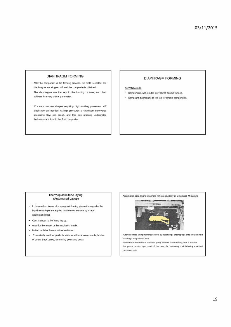
Automated tape-laying machine (photo courtesy of Cincinnati Milacron).
Automated tape-laying machines operate by dispensing a prepreg tape onto an open mold
following a programmed path .
Typical machine consists of overhead gantry to which the dispensing head is attached
The gantry permits x-y-z travel of the head, for positioning and following a defined
continuous path.