Embed Size (px)
Citation preview
TEST PROJECT TEACHER GUIDELINES
Mastercam Intro to CAD/CAM
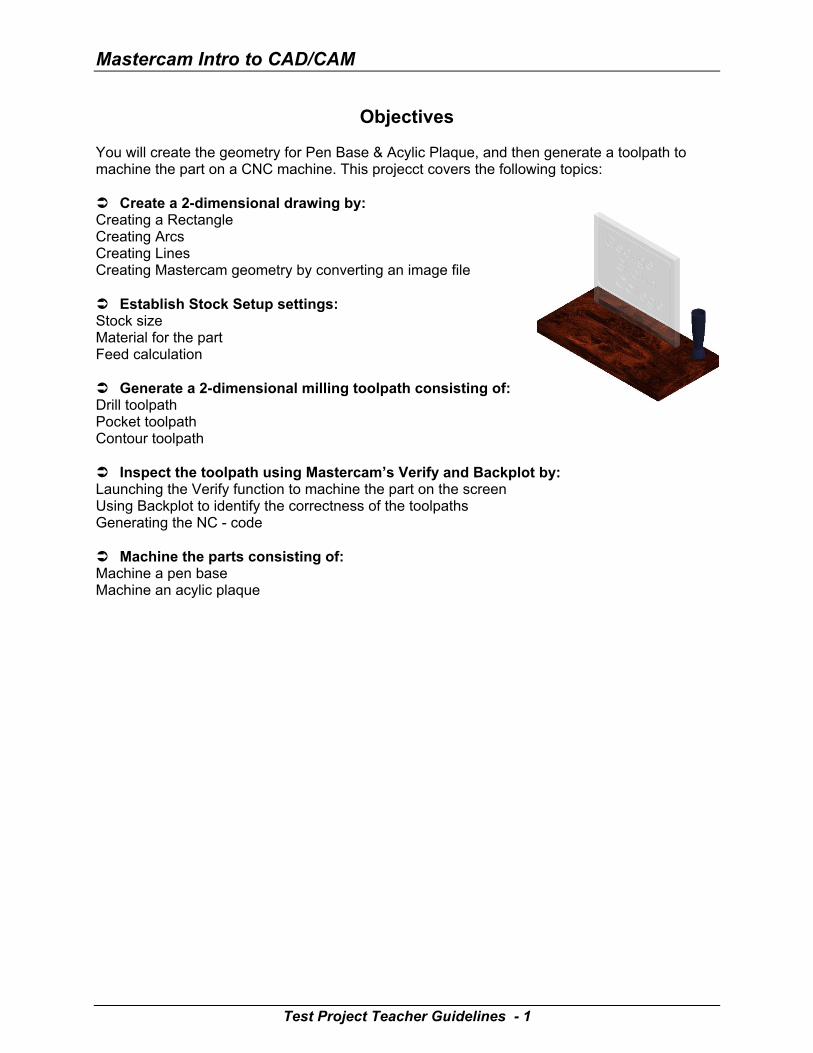
Objectives You will create the geometry for Pen Base & Acylic Plaque, and then generate a toolpath to machine the part on a CNC machine. This projecct covers the following topics: Create a 2-dimensional drawing by: Creating a Rectangle Creating Arcs Creating Lines Creating Mastercam geometry by converting an image file Establish Stock Setup settings: Stock size Material for the part Feed calculation Generate a 2-dimensional milling toolpath consisting of: Drill toolpath Pocket toolpath Contour toolpath Inspect the toolpath using Mastercam’s Verify and Backplot by: Launching the Verify function to machine the part on the screen Using Backplot to identify the correctness of the toolpaths Generating the NC - code Machine the parts consisting of: Machine a pen base Machine an acylic plaque
Test Project Teacher Guidelines - 1
Test Project
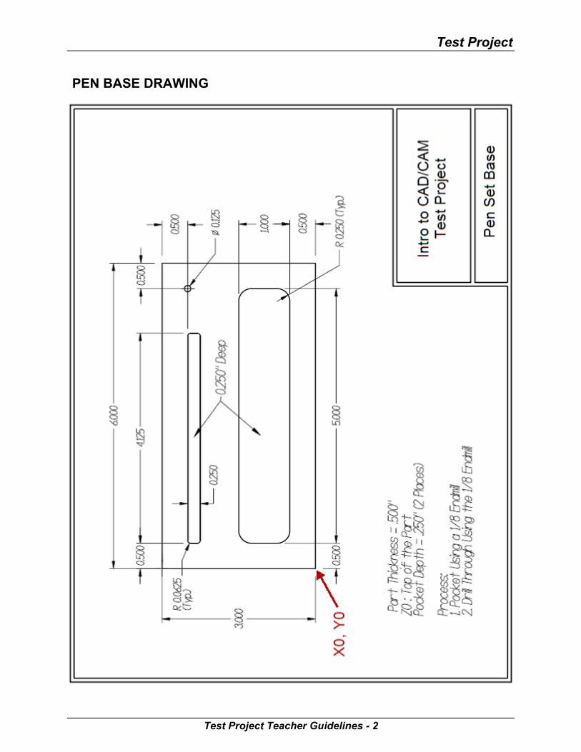
PEN BASE DRAWING
Test Project Teacher Guidelines - 2
Mastercam Intro to CAD/CAM
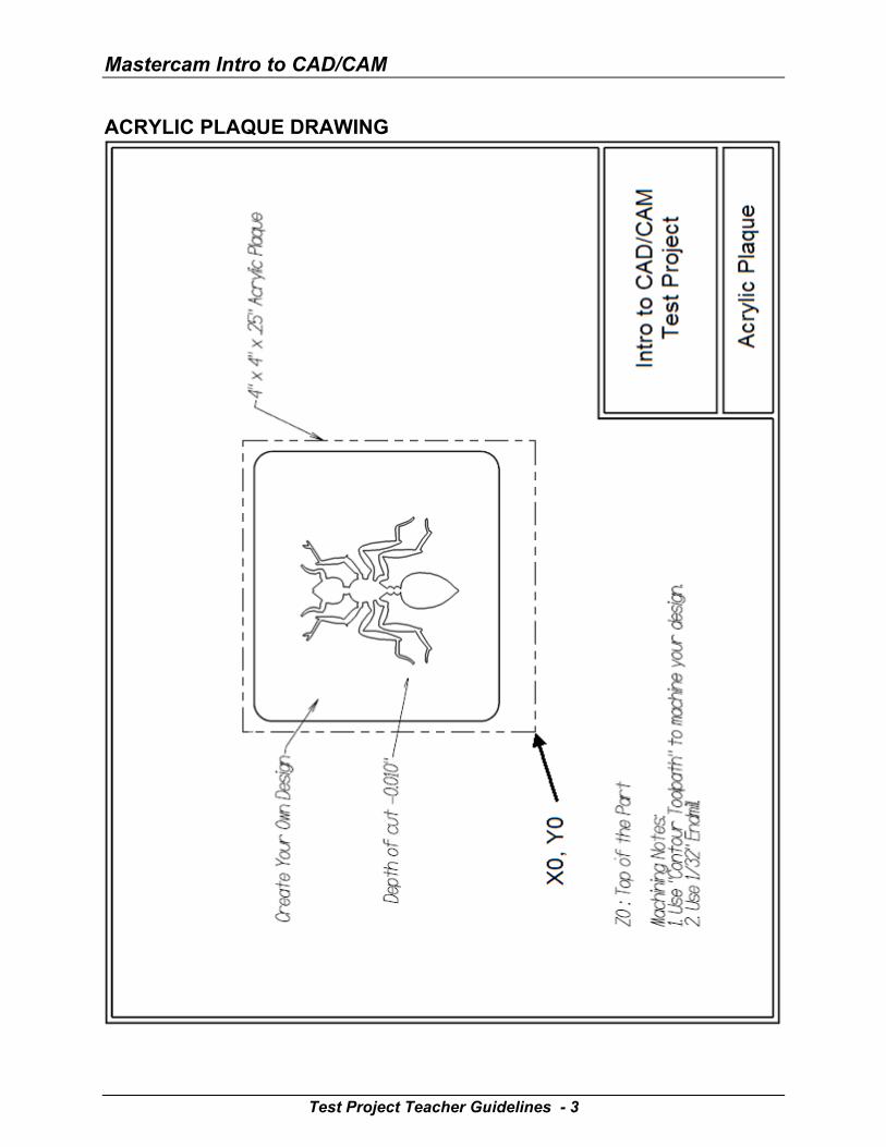
ACRYLIC PLAQUE DRAWING
Test Project Teacher Guidelines - 3
Test Project
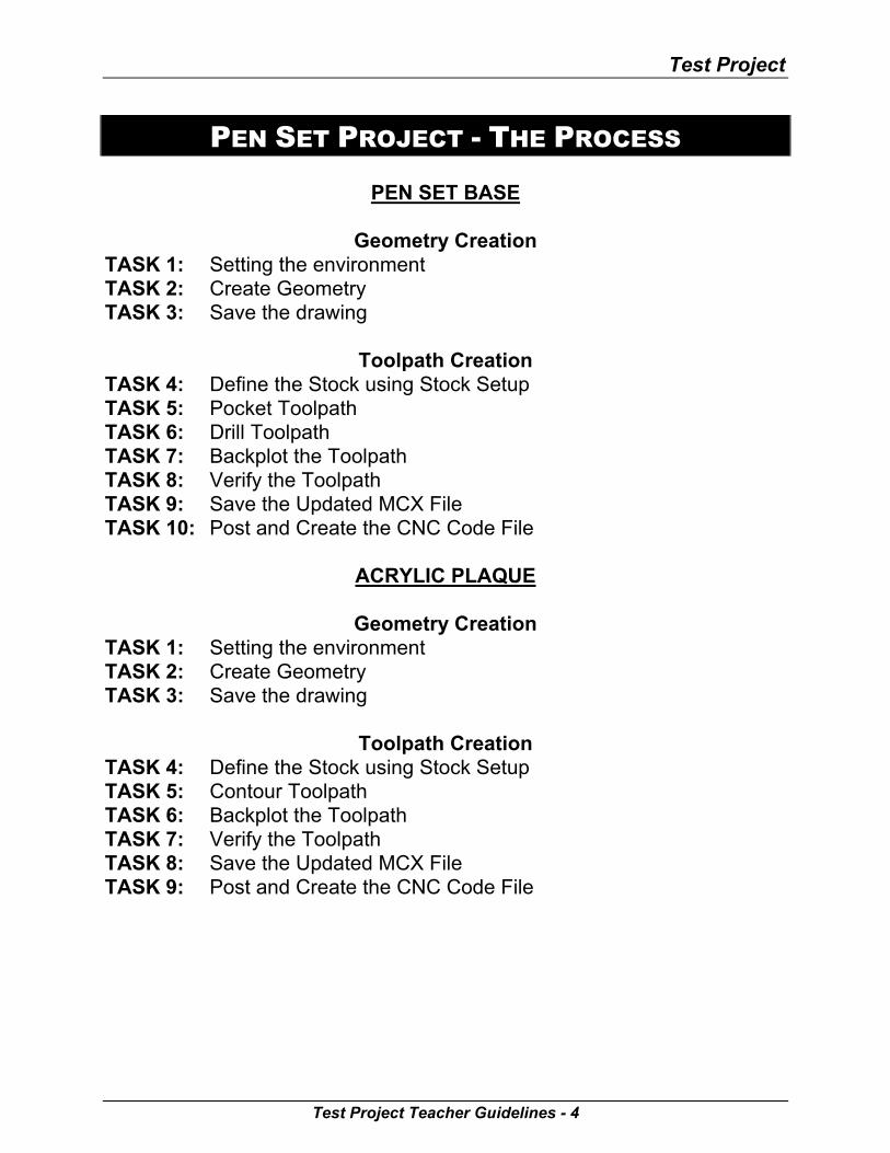
PEN SET PROJECT - THE PROCESS
PEN SET BASE
Geometry Creation TASK 1: Setting the environment TASK 2: Create Geometry TASK 3: Save the drawing
Toolpath Creation TASK 4: Define the Stock using Stock Setup TASK 5: Pocket Toolpath TASK 6: Drill Toolpath TASK 7: Backplot the Toolpath TASK 8: Verify the Toolpath TASK 9: Save the Updated MCX File TASK 10: Post and Create the CNC Code File
ACRYLIC PLAQUE
Geometry Creation TASK 1: Setting the environment TASK 2: Create Geometry TASK 3: Save the drawing
Toolpath Creation TASK 4: Define the Stock using Stock Setup TASK 5: Contour Toolpath TASK 6: Backplot the Toolpath TASK 7: Verify the Toolpath TASK 8: Save the Updated MCX File TASK 9: Post and Create the CNC Code File
Test Project Teacher Guidelines - 4
Mastercam Intro to CAD/CAM
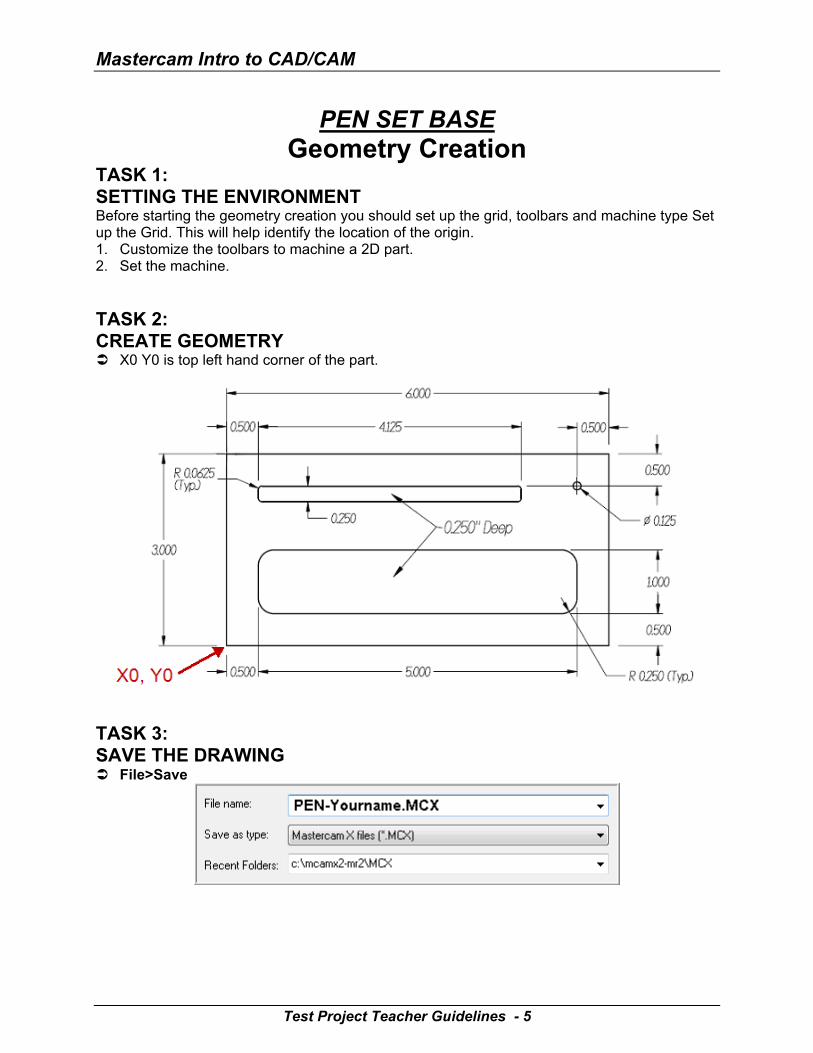
PEN SET BASE Geometry Creation
TASK 1: SETTING THE ENVIRONMENT Before starting the geometry creation you should set up the grid, toolbars and machine type Set up the Grid. This will help identify the location of the origin. 1. Customize the toolbars to machine a 2D part. 2. Set the machine.
TASK 2: CREATE GEOMETRY X0 Y0 is top left hand corner of the part.
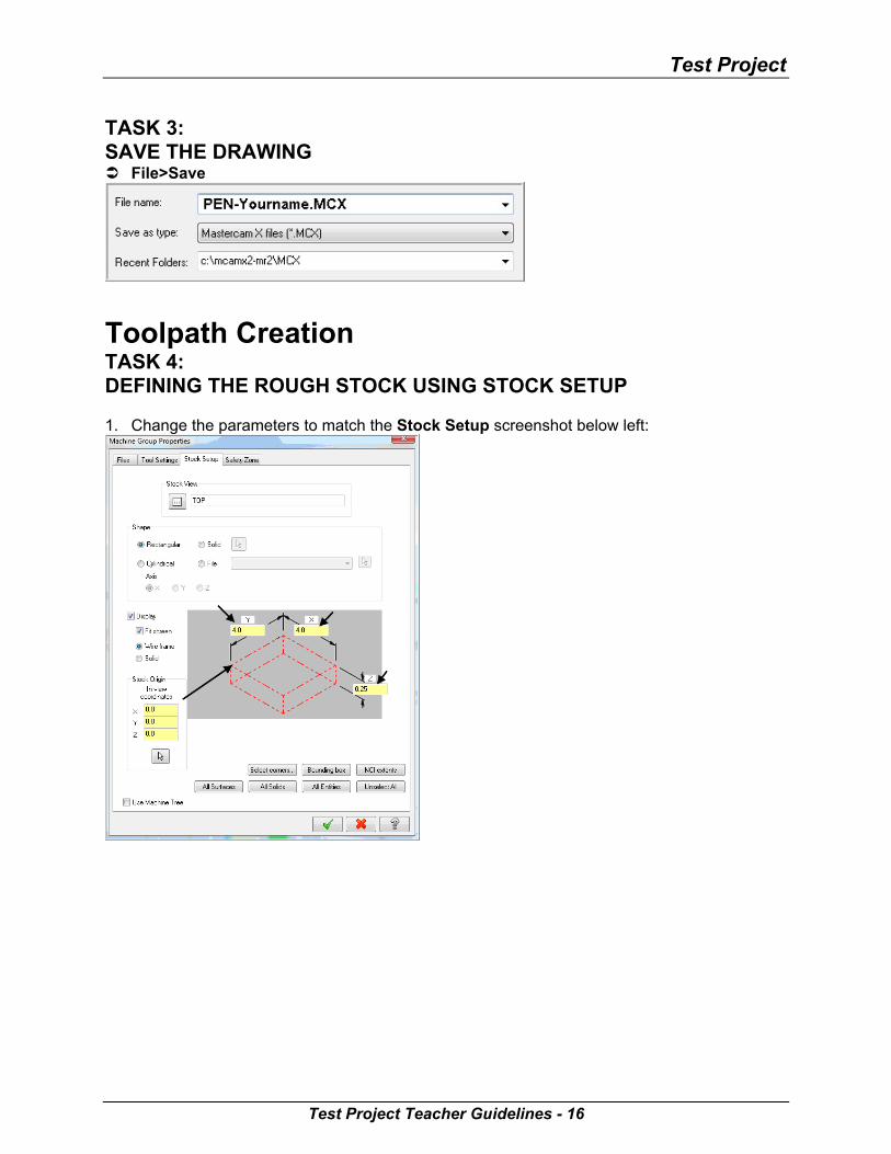
TASK 3: SAVE THE DRAWING File>Save
Test Project Teacher Guidelines - 5
Test Project
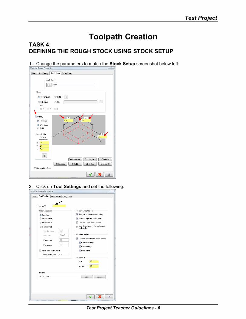
Toolpath Creation TASK 4: DEFINING THE ROUGH STOCK USING STOCK SETUP 1. Change the parameters to match the Stock Setup screenshot below left:
2. Click on Tool Settings and set the following.
Test Project Teacher Guidelines - 6
Mastercam Intro to CAD/CAM
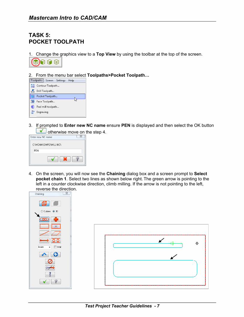
TASK 5: POCKET TOOLPATH 1. Change the graphics view to a Top View by using the toolbar at the top of the screen.
2. From the menu bar select Toolpaths>Pocket Toolpath…
3. If prompted to Enter new NC name ensure PEN is displayed and then select the OK button
otherwise move on the step 4.
4. On the screen, you will now see the Chaining dialog box and a screen prompt to Select
pocket chain 1. Select two lines as shown below right. The green arrow is pointing to the left in a counter clockwise direction, climb milling. If the arrow is not pointing to the left, reverse the direction.
Test Project Teacher Guidelines - 7
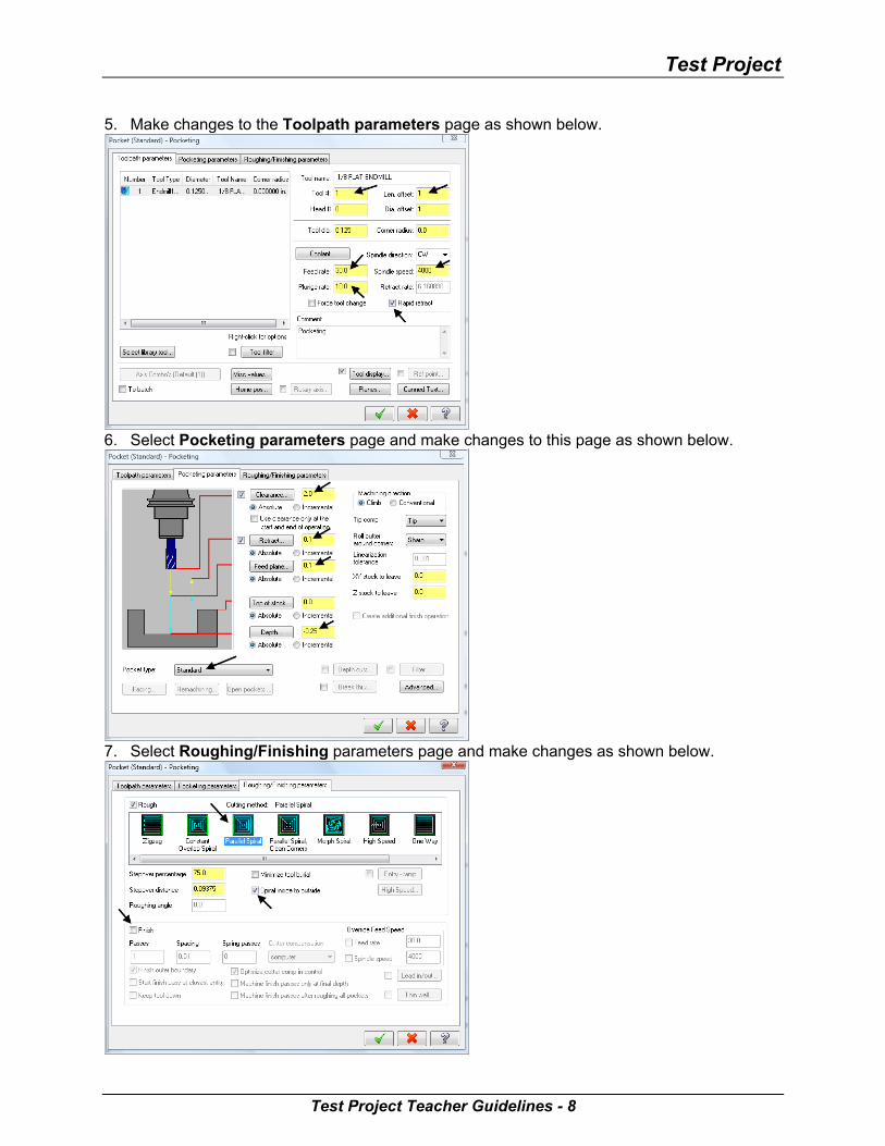
Test Project 5. Make changes to the Toolpath parameters page as shown below.
6. Select Pocketing parameters page and make changes to this page as shown below.
7. Select Roughing/Finishing parameters page and make changes as shown below.
Test Project Teacher Guidelines - 8
Mastercam Intro to CAD/CAM
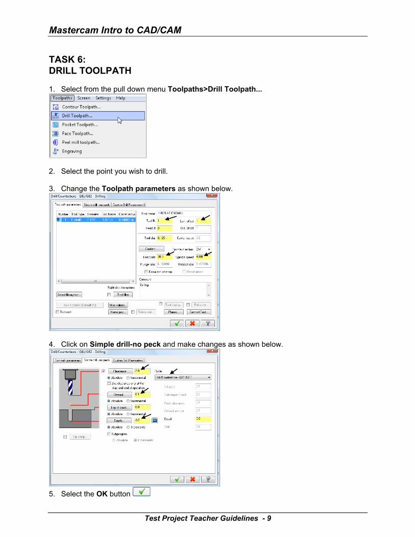
TASK 6: DRILL TOOLPATH 1. Select from the pull down menu Toolpaths>Drill Toolpath...
2. Select the point you wish to drill.
3. Change the Toolpath parameters as shown below.
4. Click on Simple drill-no peck and make changes as shown below.
5. Select the OK button
Test Project Teacher Guidelines - 9
Test Project
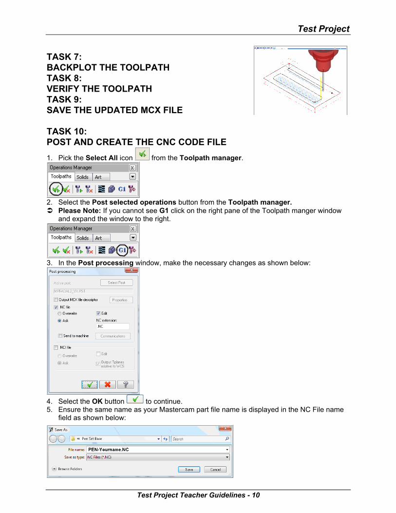
TASK 7: BACKPLOT THE TOOLPATH TASK 8: VERIFY THE TOOLPATH TASK 9: SAVE THE UPDATED MCX FILE TASK 10: POST AND CREATE THE CNC CODE FILE
1. Pick the Select All icon from the Toolpath manager.
2. Select the Post selected operations button from the Toolpath manager. Please Note: If you cannot see G1 click on the right pane of the Toolpath manger window
and expand the window to the right.
3. In the Post processing window, make the necessary changes as shown below:
4. Select the OK button to continue. 5. Ensure the same name as your Mastercam part file name is displayed in the NC File name
field as shown below:
Test Project Teacher Guidelines - 10
Mastercam Intro to CAD/CAM
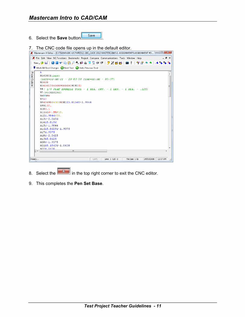
6. Select the Save button . 7. The CNC code file opens up in the default editor.
8. Select the in the top right corner to exit the CNC editor. 9. This completes the Pen Set Base.
Test Project Teacher Guidelines - 11
Test Project
ACRYLIC PLAQUE Geometry Creation
TASK 1: SETTING THE ENVIRONMENT Before starting the geometry creation you should set up the grid, toolbars and machine type Set up the Grid. This will help identify the location of the origin. 1. Customize the toolbars to machine a 2D part. 2. Set the machine type.
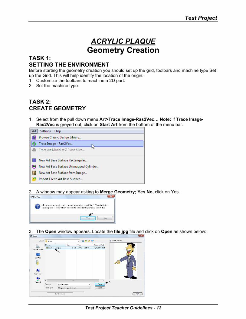
TASK 2: CREATE GEOMETRY 1. Select from the pull down menu Art>Trace Image-Ras2Vec… Note: If Trace Image-
Ras2Vec is greyed out, click on Start Art from the bottom of the menu bar.
2. A window may appear asking to Merge Geometry; Yes No, click on Yes.
3. The Open window appears. Locate the file.jpg file and click on Open as shown below:
Test Project Teacher Guidelines - 12
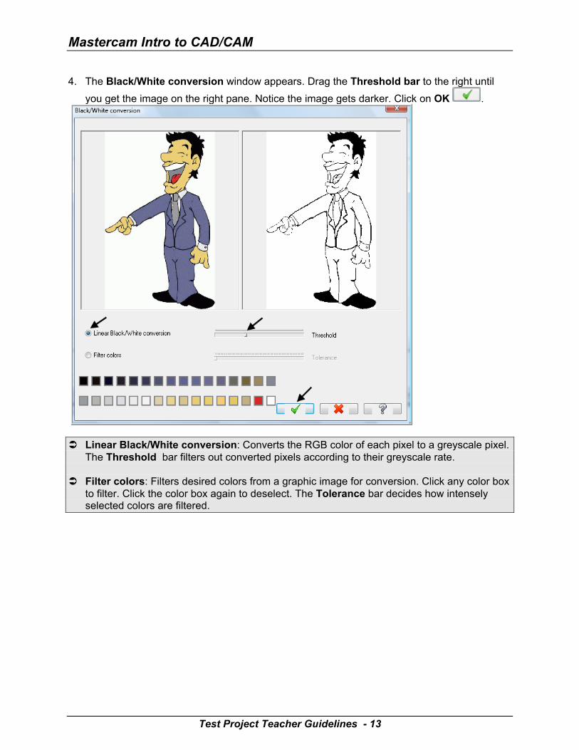
Mastercam Intro to CAD/CAM 4. The Black/White conversion window appears. Drag the Threshold bar to the right until
you get the image on the right pane. Notice the image gets darker. Click on OK .
Linear Black/White conversion: Converts the RGB color of each pixel to a greyscale pixel.
The Threshold bar filters out converted pixels according to their greyscale rate. Filter colors: Filters desired colors from a graphic image for conversion. Click any color box
to filter. Click the color box again to deselect. The Tolerance bar decides how intensely selected colors are filtered.
Test Project Teacher Guidelines - 13
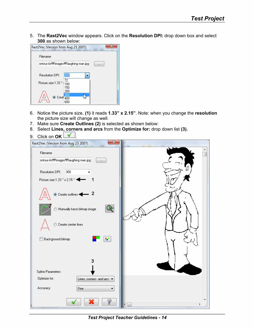
Test Project 5. The Rast2Vec window appears. Click on the Resolution DPI: drop down box and select
300 as shown below:
6. Notice the picture size, (1) it reads 1.33” x 2.15”. Note: when you change the resolution
the picture size will change as well. 7. Make sure Create Outlines (2) is selected as shown below: 8. Select Lines, corners and arcs from the Optimize for: drop down list (3).
9. Click on OK .
Test Project Teacher Guidelines - 14
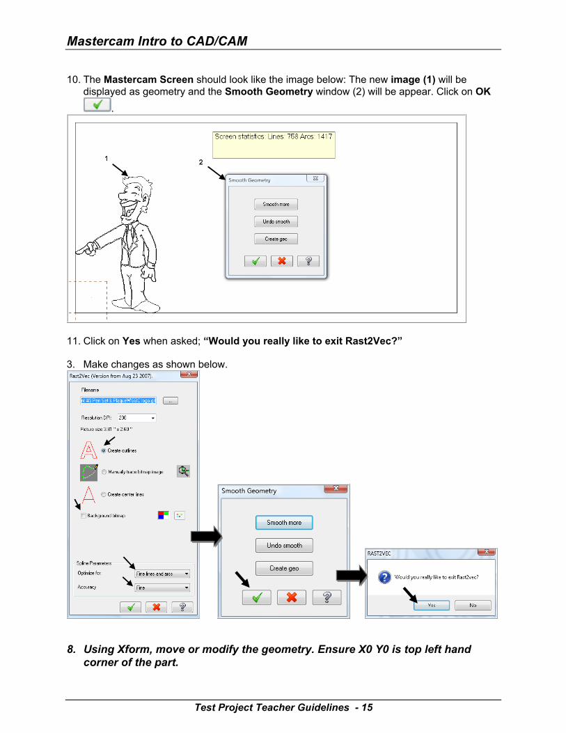
Mastercam Intro to CAD/CAM 10. The Mastercam Screen should look like the image below: The new image (1) will be
displayed as geometry and the Smooth Geometry window (2) will be appear. Click on OK
.
11. Click on Yes when asked; “Would you really like to exit Rast2Vec?” 3. Make changes as shown below.
8. Using Xform, move or modify the geometry. Ensure X0 Y0 is top left hand
corner of the part.
Test Project Teacher Guidelines - 15
Test Project
TASK 3: SAVE THE DRAWING File>Save
Toolpath Creation TASK 4: DEFINING THE ROUGH STOCK USING STOCK SETUP 1. Change the parameters to match the Stock Setup screenshot below left:
Test Project Teacher Guidelines - 16
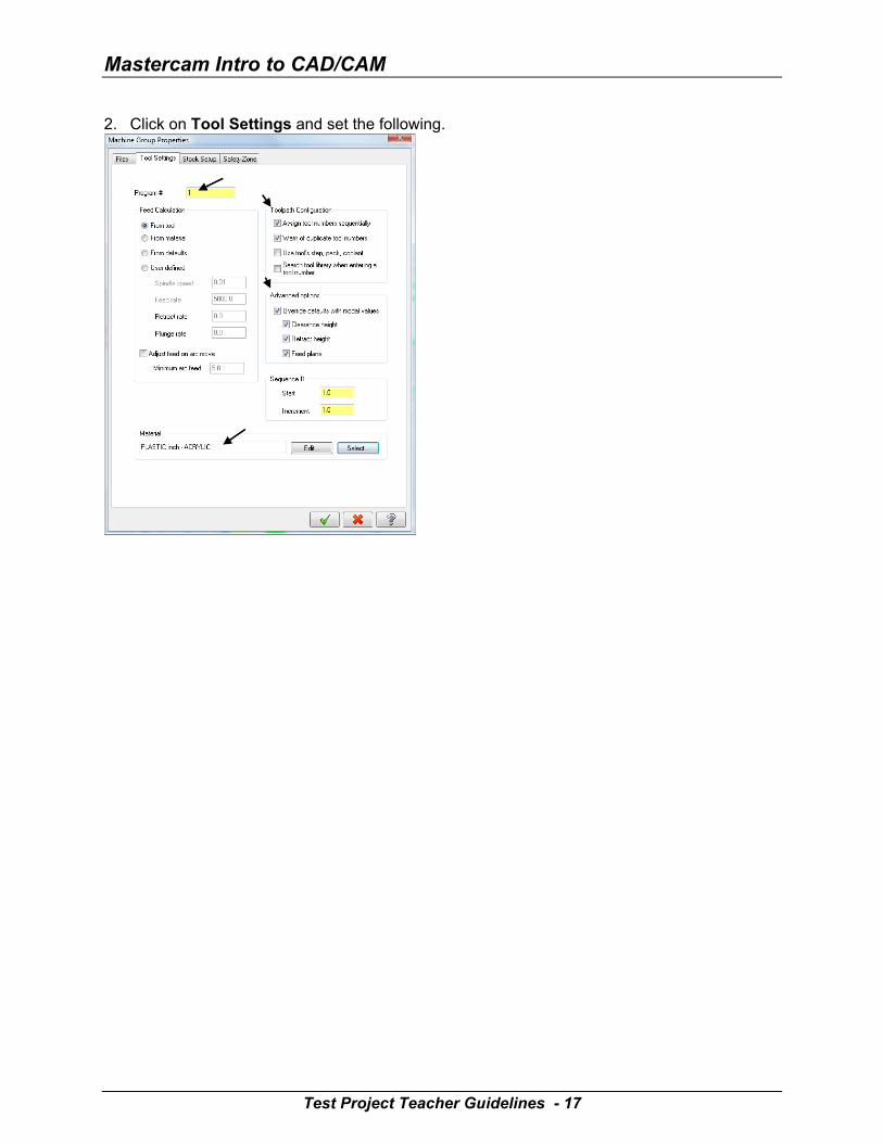
Mastercam Intro to CAD/CAM 2. Click on Tool Settings and set the following.
Test Project Teacher Guidelines - 17
Test Project
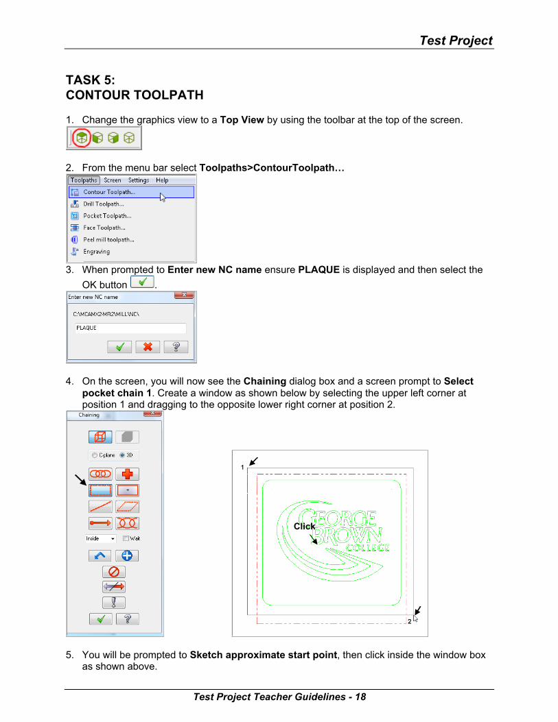
TASK 5: CONTOUR TOOLPATH 1. Change the graphics view to a Top View by using the toolbar at the top of the screen.
2. From the menu bar select Toolpaths>ContourToolpath…
3. When prompted to Enter new NC name ensure PLAQUE is displayed and then select the
OK button .
4. On the screen, you will now see the Chaining dialog box and a screen prompt to Select
pocket chain 1. Create a window as shown below by selecting the upper left corner at position 1 and dragging to the opposite lower right corner at position 2.
Click
5. You will be prompted to Sketch approximate start point, then click inside the window box
as shown above.
Test Project Teacher Guidelines - 18

Mastercam Intro to CAD/CAM 6. Make changes to the Toolpath parameters page as shown below.
7. Select Contour parameters page and make changes to this page as shown below.
8. Select the OK button
Test Project Teacher Guidelines - 19
Test Project
TASK 6: BACKPLOT THE TOOLPATH TASK 7: VERIFY THE TOOLPATH TASK 8: SAVE THE UPDATED MCX FILE TASK 9: POST AND CREATE THE CNC CODE FILE
1. Pick the Select All icon from the Toolpath manager.
2. Select the Post selected operations button from the Toolpath manager. Please Note: If you cannot see G1 click on the right pane of the Toolpath manger window
and expand the window to the right.
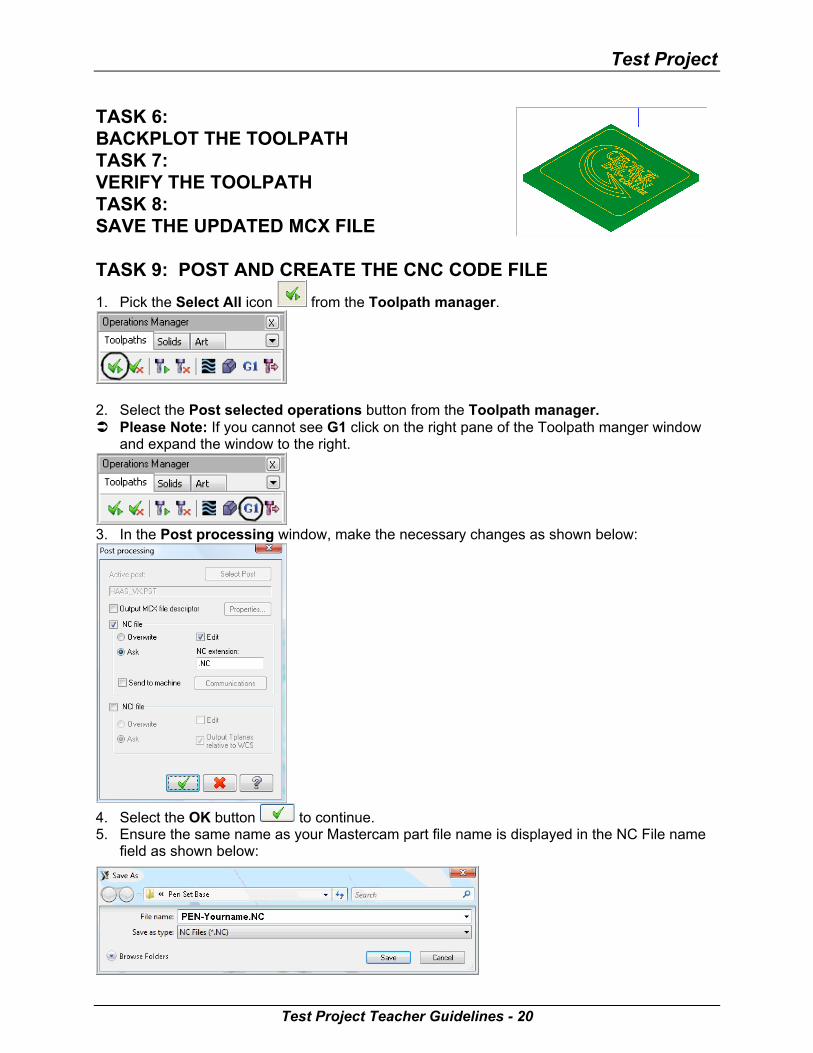
3. In the Post processing window, make the necessary changes as shown below:
4. Select the OK button to continue. 5. Ensure the same name as your Mastercam part file name is displayed in the NC File name
field as shown below:
Test Project Teacher Guidelines - 20
Mastercam Intro to CAD/CAM
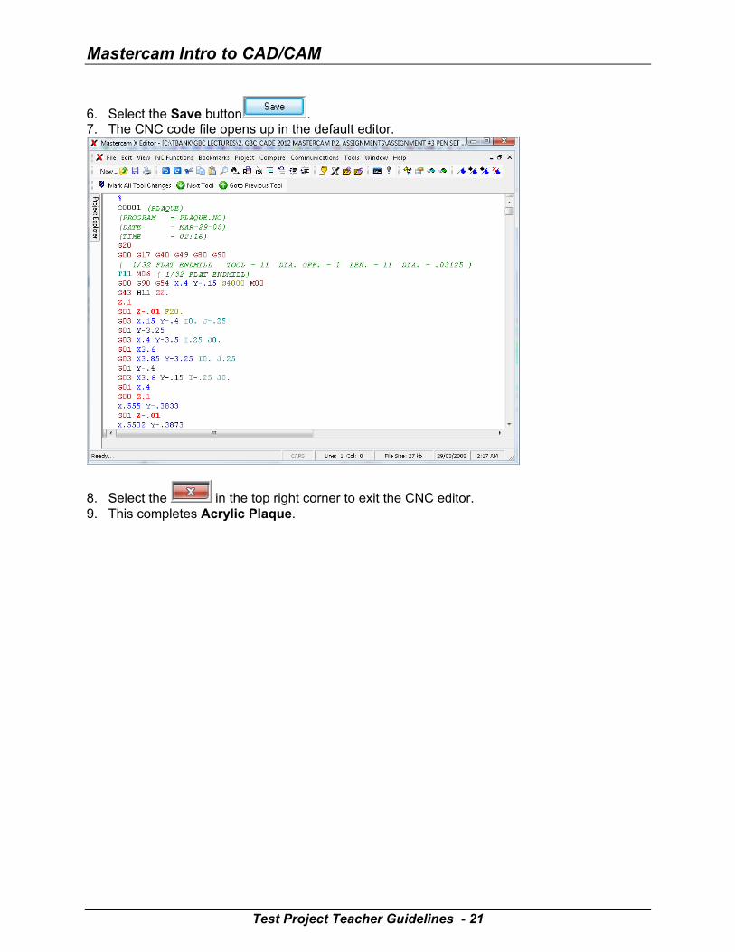
6. Select the Save button . 7. The CNC code file opens up in the default editor.
8. Select the in the top right corner to exit the CNC editor. 9. This completes Acrylic Plaque.
Test Project Teacher Guidelines - 21
Test Project
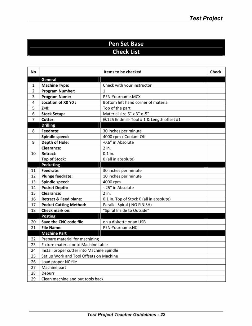
Pen Set Base
Check List
No Items to be checked Check
General 1 Machine Type: Check with your instructor 2 Program Number: 1 3 Program Name: PEN-Yourname.MCX 4 Location of X0 Y0 : Bottom left hand corner of material 5 Z=0: Top of the part 6 Stock Setup: Material size 6” x 3” x .5” 7 Cutter: Ø.125 Endmill- Tool # 1 & Length offset #1 Drilling
8 Feedrate: 30 inches per minute Spindle speed: 4000 rpm / Coolant Off
9 Depth of Hole: -0.6” in Absolute
10 Clearance: Retract: Top of Stock:
2 in. 0.1 in. 0 (all in absolute)
Pocketing 11 Feedrate: 30 inches per minute 12 Plunge feedrate: 10 inches per minute 13 Spindle speed: 4000 rpm 14 Pocket Depth: -.25” in Absolute 15 Clearance: 2 in. 16 Retract & Feed plane: 0.1 in. Top of Stock 0 (all in absolute) 17 Pocket Cutting Method: Parallel Spiral ( NO FINISH) 18 Check mark on: “Spiral Inside to Outside”
Posting 20 Save the CNC code file: on a diskette or an USB 21 File Name: PEN-Yourname.NC
Machine Part 22 Prepare material for machining 23 Fixture material onto Machine table 24 Install proper cutter into Machine Spindle 25 Set up Work and Tool Offsets on Machine 26 Load proper NC file 27 Machine part 28 Deburr 29 Clean machine and put tools back
Test Project Teacher Guidelines - 22
Mastercam Intro to CAD/CAM
Test Project Teacher Guidelines - 23
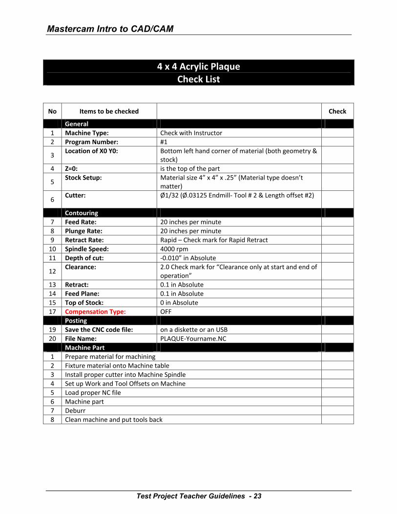
4 x 4 Acrylic Plaque Check List
No Items to be checked Check
General 1 Machine Type: Check with Instructor 2 Program Number: #1
3 Location of X0 Y0: Bottom left hand corner of material (both geometry &
stock)
4 Z=0: is the top of the part
5 Stock Setup: Material size 4” x 4” x .25” (Material type doesn’t
matter)
6 Cutter:
Ø1/32 (Ø.03125 Endmill- Tool # 2 & Length offset #2)
Contouring 7 Feed Rate: 20 inches per minute 8 Plunge Rate: 20 inches per minute 9 Retract Rate: Rapid – Check mark for Rapid Retract
10 Spindle Speed: 4000 rpm 11 Depth of cut: -0.010” in Absolute
12 Clearance: 2.0 Check mark for “Clearance only at start and end of
operation”
13 Retract: 0.1 in Absolute 14 Feed Plane: 0.1 in Absolute 15 Top of Stock: 0 in Absolute 17 Compensation Type: OFF
Posting 19 Save the CNC code file: on a diskette or an USB 20 File Name: PLAQUE-Yourname.NC
Machine Part 1 Prepare material for machining 2 Fixture material onto Machine table 3 Install proper cutter into Machine Spindle 4 Set up Work and Tool Offsets on Machine 5 Load proper NC file 6 Machine part 7 Deburr 8 Clean machine and put tools back