Embed Size (px)
Citation preview
‘Surfacing’ is a machining operation in which a 3D contoured surface is carved from a block of stock material through a series of cuts. Typically this is done in two operations, a ‘Rough’ pass and a ‘Finish’ pass. The purpose of the ‘Rough’ pass is to remove as much material in as quick of time as possible, this is typically done with a large bit and gives a rough couduroy texture to the material. Often the process is stopped after the ‘Rough’ process, and if the roughing operation is done with a small enough bit the surface smoothness may be suitable for many applications. If a smoother finished surface is desirable a second series of cuts can be made with a smaller bit at a tighter interval giving a smooth polished surface. This tutorial covers the basic opera-tions needed to do a ‘Rough’ tool path based on a generic 3D surface.
Surface Creation
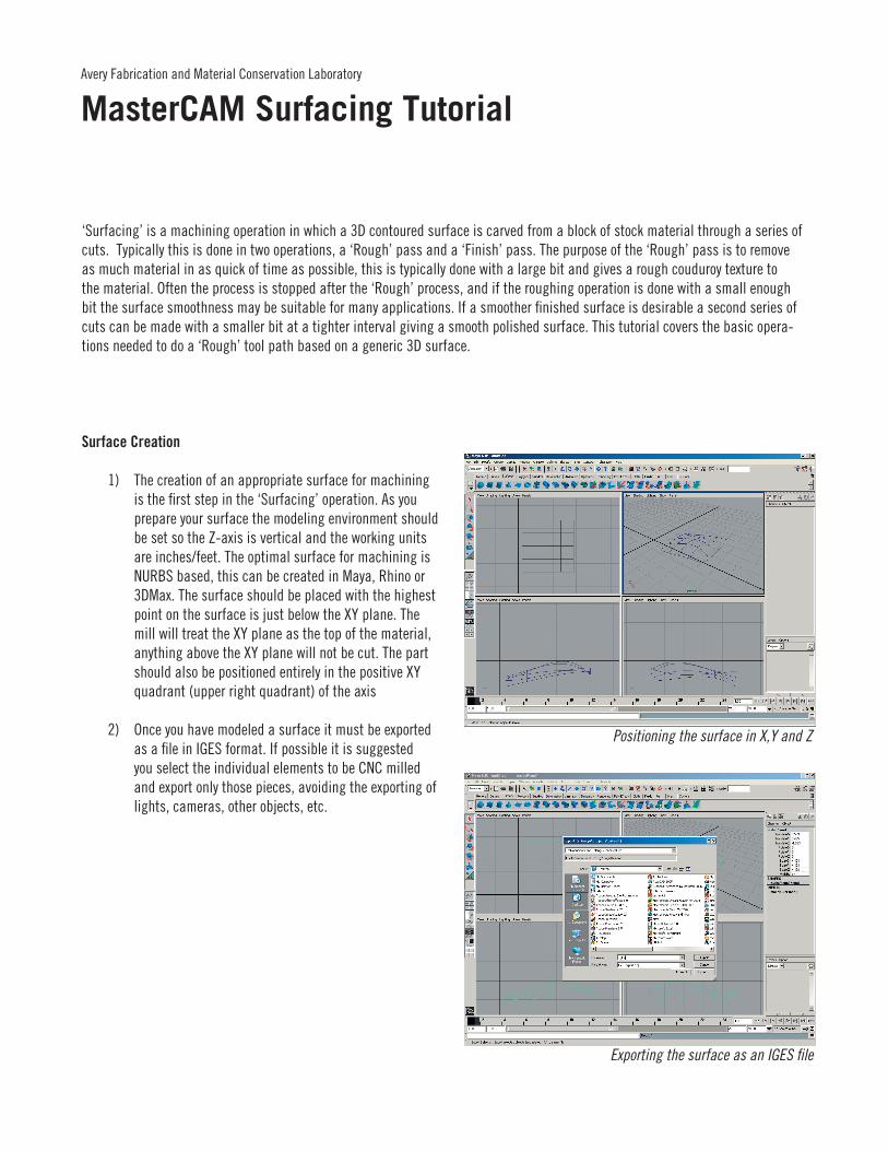
1) The creation of an appropriate surface for machining is the first step in the ‘Surfacing’ operation. As you prepare your surface the modeling environment should be set so the Z-axis is vertical and the working units are inches/feet. The optimal surface for machining is NURBS based, this can be created in Maya, Rhino or 3DMax. The surface should be placed with the highest point on the surface is just below the XY plane. The mill will treat the XY plane as the top of the material, anything above the XY plane will not be cut. The part should also be positioned entirely in the positive XY quadrant (upper right quadrant) of the axis
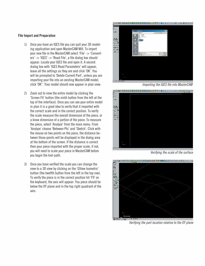
2) Once you have modeled a surface it must be exported as a file in IGES format. If possible it is suggested you select the individual elements to be CNC milled and export only those pieces, avoiding the exporting of lights, cameras, other objects, etc.
Avery Fabrication and Material Conservation Laboratory
MasterCAM Surfacing Tutorial
Positioning the surface in X,Y and Z
Exporting the surface as an IGES file
File Import and Preparation
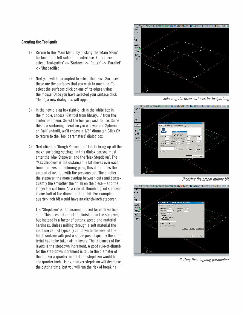
1) Once you have an IGES file you can quit your 3D model-ing application and open MasterCAM Mill. To import your new file in the MasterCAM select ‘File’ -> ‘Convert-ers’ -> ‘IGES’ -> ‘Read File’, a file dialog box should appear. Locate your IGES file and open it. A second dialog box with ‘IGES Read Parameters’ will appear, leave all the settings as they are and click ‘OK’. You will be prompted to ‘Delete Current Part’, unless you are importing your file into an existing MasterCAM model, click ‘OK”. Your model should now appear in plan view.
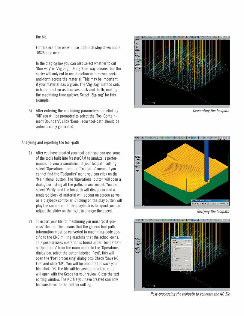
2) Zoom out to view the entire model by clicking the ‘Screen Fit’ button (the ninth button from the left at the top of the interface). Once you can see your entire model in plan it is a good idea to verify that it imported with the correct scale and in the correct position. To verify the scale measure the overall dimension of the piece, or a know dimension of a portion of the piece. To measure the piece, select ‘Analyze’ from the main menu. From ‘Analyze’ choose ‘Between Pts’ and ‘Sketch’. Click with the mouse on two points on the piece, the distance be-tween those points will be displayed in the dialog area at the bottom of the screen. If the distance is correct then your piece imported with the proper scale, if not, you will need to scale your piece in MasterCAM before you begin the tool-path.
3) Once you have verified the scale you can change the view to a 3D view by clicking on the ‘GView Isometric’ button (the twelfth button from the left in the top row). To verify the piece is in the correct position hit ‘F9’ on the keyboard, the axis will appear. You piece should be below the XY plane and in the top right quadrant of the axis.
Importing the IGES file into MasterCAM
Verifying the scale of the surface
Verifying the part location relative to the XY plane
Creating the Tool-path
1) Return to the ‘Main Menu’ by clicking the ‘Main Menu’ button on the left side of the interface. From there select ‘Tool-paths’ -> ‘Surface’ -> ‘Rough’ -> ‘Parallel’ -> ‘Unspecified’.
2) Next you will be prompted to select the ‘Drive Surfaces’, these are the surfaces that you wish to machine. To select the surfaces click on one of its edges using the mouse. Once you have selected your surface click ‘Done’, a new dialog box will appear.
3) In the new dialog box right-click in the white box in the middle, choose ‘Get tool from library…’ from the contextual menu. Select the tool you wish to use. Since this is a surfacing operation you will was an ‘Spherical’ or ‘Ball’ endmill, we’ll choose a 1/8” diameter. Click OK to return to the ‘Tool parameters’ dialog box.
4) Next click the ‘Rough Parameters’ tab to bring up all the rough surfacing settings. In this dialog box you must enter the ‘Max Stepover’ and the ‘Max Stepdown’. The ‘Max Stepover’ is the distance the bit moves over each time it makes a machining pass, this determines the amount of overlap with the previous cut. The smaller the stepover, the more overlap between cuts and conse-quently the smoother the finish on the piece – and the longer the cut time. As a rule-of-thumb a good stepover is one-half of the diameter of the bit. For example, a quarter-inch bit would have an eighth-inch stepover.
The ‘Stepdown’ is the increment used for each vertical step. This does not affect the finish as in the stepover, but instead is a factor of cutting speed and material hardness. Unless milling through a soft material the machine cannot typically cut down to the level of the finish surface with just a single pass, typically the ma-terial has to be taken off in layers. The thickness of the layers is the stepdown increment. A good rule-of-thumb for the step-down increment is to use the diameter of the bit. For a quarter-inch bit the stepdown would be one quarter inch. Using a larger stepdown will decrease the cutting time, but you will run the risk of breaking
Verifying the scale of the surface
Verifying the part location relative to the XY plane
Selecting the drive surfaces for toolpathing
Choosing the proper milling bit
Setting the roughing parameters
the bit.
For this example we will use .125 inch step down and a .0625 step over.
In the diaglog box you can also select whether to cut ‘One-way’ or ‘Zig-zag’. Using ‘One-way’ means that the cutter will only cut in one direction as it moves back-and-forth across the material. This may be important if your material has a grain. The ‘Zig-zag’ method cuts in both direction as it moves back-and-forth, making the machining time quicker. Select ‘Zig-zag’ for this example.
5) After entering the machining parameters and clicking ‘OK’ you will be prompted to select the ‘Tool Contain-ment Boundary’, click ‘Done’. Your tool-path should be automatically generated.
Analyzing and exporting the tool-path
1) After you have created your tool-path you can use some of the tools built into MasterCAM to analyze is perfor-mance. To view a simulation of your toolpath cutting select ‘Operations’ from the ‘Toolpaths’ menu. If you cannot find the ‘Toolpaths’ menu you can click on the ‘Main Menu’ button. The ‘Operations’ button will open a dialog box listing all the paths in your model. You can select ‘Verify’ and the toolpath will disappear and a rendered block of material will appear on screen as well as a playback controller. Clicking on the play button will play the simulation. If the playback is too quick you can adjust the slider on the right to change the speed.
2) To export your file for machining you must ‘post-pro-cess’ the file. This means that the generic tool-path information must be converted to machining-code spe-cific to the CNC milling machine that the school owns. This post-process operation is found under ‘Toolpaths’->’Operations’ from the main menu. In the ‘Operations’ dialog box select the button labeled ‘Post’, this will open the ‘Post processing’ dialog box. Check ‘Save NC File’ and click ‘OK’. You will be prompted to save your file, click ‘OK. The file will be saved and a text editor will open with the Gcode for your review. Close the text editing window. The NC file you have created can now be transferred to the mill for cutting.
Generating the toolpath
Verifying the toolpath
Post-processing the toolpath to generate the NC file