Embed Size (px)
Citation preview
Master thesis and internship proposals
for the Academic year 2017-2018, BruFacE, Electromechanical engineering
ULB, BEAMS dpt, Electrical energy group
Academic promoter/supervisor: J. Gyselinck ([email protected])
(last update: 02/05/2017)
1. Integration of module-level power optimizers in a photovoltaic system
2. Design of a single-phase grid-tied inverter
3. Implementation of a standalone controller for electrical machines
4. High-performance control of a flywheel energy storage system
5. Comparative study of PMSMs and PM-less motors for electrical-vehicle traction
6. Advanced prototyping for electrical vehicle components (+ internship at Siemens)
7. Electric signature diagnosis for critical production processes (+ internship at Siemens)
8. Automatic testing and parameter identification of PMSM drives (+ internship at Siemens)
9. Nonlinear controller design for PMSMs (+ internship at Siemens)
10. Examining machine/grid interaction in electrical power generation: a focus on the observability of shaft torque variations in electrical measurements (+ internship at Laborelec)
11. LabVIEW model development of an Alstom power converter for simulation purpose (+ internship at Alstom)
12. Design and control of PMSMs for automotive applications (+ internship at Brose)
13. Design and optimization of a wound rotor induction machine prototype used for combined rotating and power transfer functions (+ internship at Thales Alenia Space)
14. Modelling and characterization of magnetics used for power conversion (+ internship at Thales Alenia Space)
15. Numerical and experimental study of a wound-rotor induction machine with variable rotor eccentricity
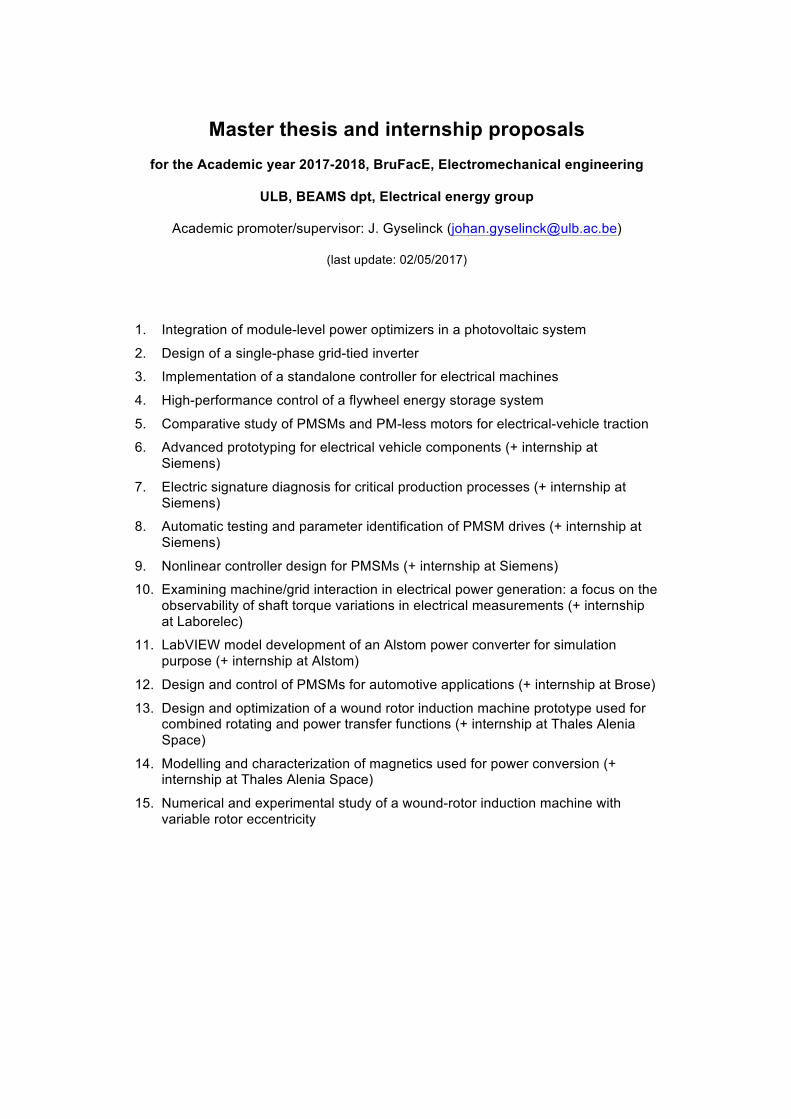
Title: Integration of module-level power optimizers in a photovoltaic system Academic Promotor: Johan GYSELINCK Supervisors: Ramón LÓPEZ ([email protected]), Ander GONZÁLEZ ([email protected]) Details: Context of the work Solar power optimizers (SPO) serve to maximize the energy harvest from each individual photovoltaic (PV) panel. These optimizers are, basically, step-up DC-DC converters that track the maximum power point (MPP) of the PV panel. The integration of these dedicated module-level converters can pleasantly improve the production of energy of a PV array. The set of converters can be connected to an inverter in order to integrate the production with the utility grid. As these SPOs can operate each of them independently from the others, the maximum level of modularity can be obtained, increasing the flexibility of the system. Even though, extracting the maximum available power in such systems is not always achievable. So as to optimize the performance of the PV system, control strategies that take into account its operating range can be implemented.
Fig. 1. Power optimizer from TIGO
Description of the work In this master thesis, the student will be asked to develop and implement a control strategy that improves the overall efficiency of the PV system. This have to deal with the different working points of the panels in the same array and the change in irradiation over the time. The goal is to study the behavior of the integration of power optimizers and carry out an appropriate control strategy. The student has to select a proper control architecture and the corresponding hardware. The converters will be installed in the PV panels of the rooftop to validate the simulation results. Requested skills Knowledge in Power Electronics and Matlab Simulink or C programming language.
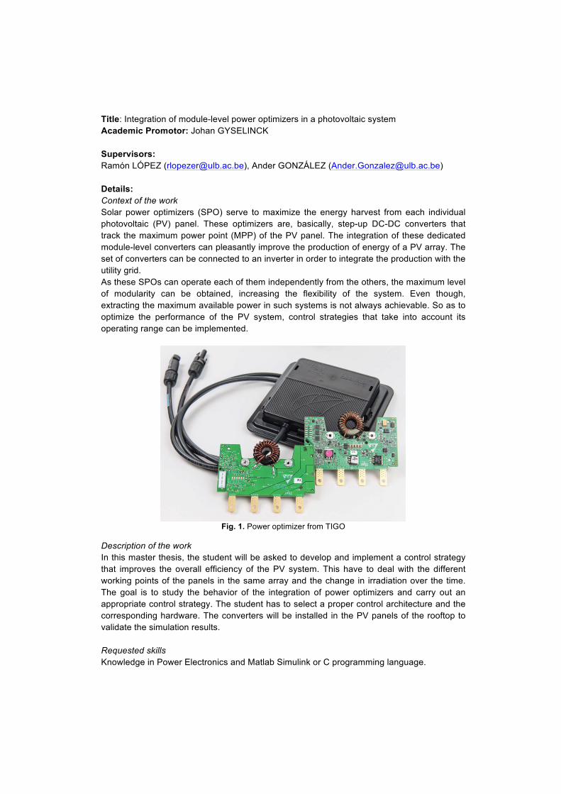
Title: Design of a single-phase grid-tied inverter. Academic Promotor: Johan GYSELINCK Supervisors: Ander GONZÁLEZ ([email protected]), Ramón LÓPEZ ([email protected]) Details: Context of the work In order to connect renewable energy sources to the loads a widespread solution is connecting them to the utility grid. For that purpose, an inverter that converts the DC power to AC has to be placed. The connection of power electronic converters into the grid requires a proper harmonic filter so as to ensure the proper and reliable operation of the utility grid.
Fig. 1. Solar micro-inverter from TI
Description of the work In this master thesis, the student will be asked to design a grid-tied inverter for renewable energy generation. The objective is to design the power electronics stage, current filter and control. The control has to be able to keep the DC-bus voltage at the required voltage that depends on the actual power generation and the grid voltage. This will be developed in a Texas Instruments’ C2000 family DSP. Requested skills Knowledge in Power Electronics, Matlab Simulink and C programming language.
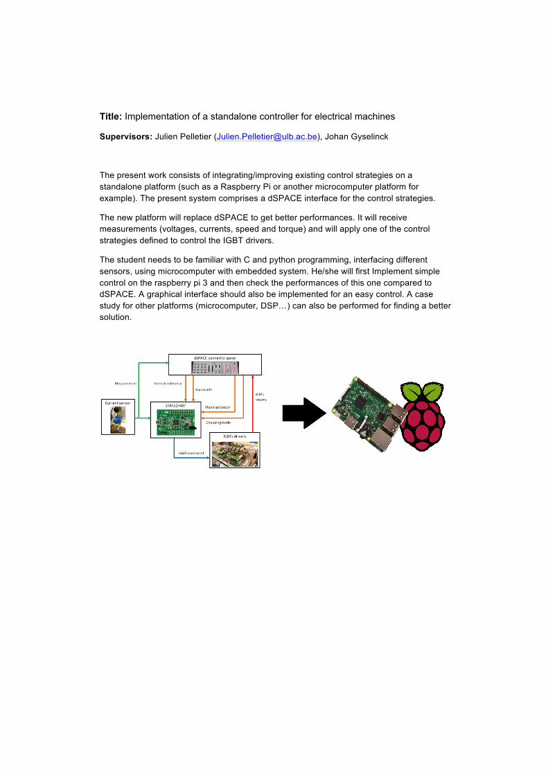
Title: Implementation of a standalone controller for electrical machines
Supervisors: Julien Pelletier ([email protected]), Johan Gyselinck
The present work consists of integrating/improving existing control strategies on a standalone platform (such as a Raspberry Pi or another microcomputer platform for example). The present system comprises a dSPACE interface for the control strategies.
The new platform will replace dSPACE to get better performances. It will receive measurements (voltages, currents, speed and torque) and will apply one of the control strategies defined to control the IGBT drivers.
The student needs to be familiar with C and python programming, interfacing different sensors, using microcomputer with embedded system. He/she will first Implement simple control on the raspberry pi 3 and then check the performances of this one compared to dSPACE. A graphical interface should also be implemented for an easy control. A case study for other platforms (microcomputer, DSP…) can also be performed for finding a better solution.
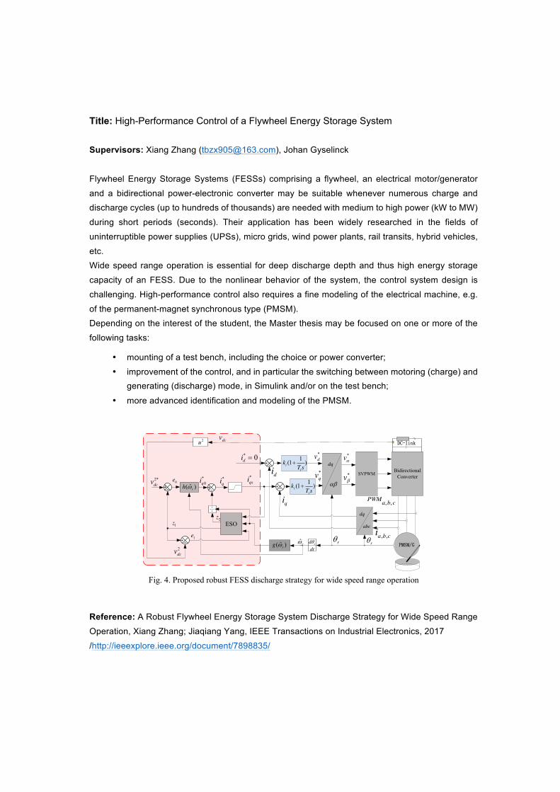
Title: High-Performance Control of a Flywheel Energy Storage System Supervisors: Xiang Zhang ([email protected]), Johan Gyselinck
Flywheel Energy Storage Systems (FESSs) comprising a flywheel, an electrical motor/generator
and a bidirectional power-electronic converter may be suitable whenever numerous charge and discharge cycles (up to hundreds of thousands) are needed with medium to high power (kW to MW)
during short periods (seconds). Their application has been widely researched in the fields of
uninterruptible power supplies (UPSs), micro grids, wind power plants, rail transits, hybrid vehicles,
etc. Wide speed range operation is essential for deep discharge depth and thus high energy storage
capacity of an FESS. Due to the nonlinear behavior of the system, the control system design is
challenging. High-performance control also requires a fine modeling of the electrical machine, e.g.
of the permanent-magnet synchronous type (PMSM). Depending on the interest of the student, the Master thesis may be focused on one or more of the
following tasks:
• mounting of a test bench, including the choice or power converter;
• improvement of the control, and in particular the switching between motoring (charge) and generating (discharge) mode, in Simulink and/or on the test bench;
• more advanced identification and modeling of the PMSM.
Reference: A Robust Flywheel Energy Storage System Discharge Strategy for Wide Speed Range
Operation, Xiang Zhang; Jiaqiang Yang, IEEE Transactions on Industrial Electronics, 2017
/http://ieeexplore.ieee.org/document/7898835/
4
2) The proposed speed adaptive control law Since the outer loop dynamic is much slower than the inner
loop, the delay of the inner current loop can be neglected when designing the DC-link voltage loop controller, that is 𝑖𝑞 = 𝑖𝑞∗ .
According to [21], the role of integral effect in eliminating steady-state error in PI strategy could be considered with the compensation of the total disturbance observed by ESO. Therefore, the ESO-based DC-link loop control law could be expressed as (25), in which y* is the reference value of y.
*
0 1
*0 0
* * 20
-
ˆ( )
q v
q qr
e y z
i k ezu i i
g Z
°
° �®°
�°¯
(25)
However, (25) is not suitable for system (22) with a time-varying speed dependent gain 𝑔(�̂�𝑟). Thus, modification has to be made.
Considering the variation of 𝑔(�̂�𝑟) is caused by the wide-range speed variation, a speed adaptive function ℎ(�̂�𝑟) needs to be designed. Replacing 𝑘𝑣 with ℎ(�̂�𝑟) in (25), the speed adaptive feedback law is expressed as (26). * 2
0ˆ )ˆq r
r
zu i h eg
ZZ
� �(( )
(26)
By substituting (26) back to the DC-link voltage loop model (22), (27) is derived. 1
2 2 0ˆ ˆr rdx x z h g edt
Z Z � � ( ) ( ) (27)
Supposing the total disturbance 𝑥2 is eliminated by the compensation of 𝑧2 , (28) is derived by substituting g(�̂�𝑟) =−3�̂�𝑟�̂�𝑚 / �̂� to (27). 1
0
ˆ3 ˆ ˆ )ˆm
r rdx h edt C
\ Z Z � ( (28)
To eliminate the effect of �̂�𝑟, ℎ(�̂�𝑟) could be defined as
1 ˆ ˆ ˆ/ (3 )r v m rk h KZ \ Z ( ) (29)
By substituting (29) into (28), (30) is derived in which the influence of �̂�𝑟 is totally decoupled. 1
0 0
ˆ3 ˆ ˆ )ˆ ˆm v
r rKdx h e e
dt C C\ Z Z � �(
(30)
Considering the current saturation in practical FESS and supposing that the saturation value of 𝑖𝑞∗ is 𝑖𝑞𝑚𝑎𝑥 , the proposed speed adaptive control law is expressed as (31).
*
0 1*
0 0
* * 20
* *
-ˆ
ˆ( )
q r
q qr
qs q
e y zi h e
zi ig
u i Sat i
Z
Z
° �°°® �°°
°̄
( )
( )
(31)
where the saturation function is defined as
*max max
* * *max max
*max max
, ( ) ,
,
q q q
q q q q q
q q q
i i iSat i i i i i
i i i
� � �° � d d®° !¯
(32)
For the convenience of the digital hardware implementation, the proposed strategy is expressed in discrete time form as (33), in which h is the sample step, and k denotes the kth sample instance.
2
2
* *
1 1
2 2 2 1 2 2
1 1 2 1 1 1 1*
0 1*
0 0*
( ) ( ) ( ) ( )
( ) ( -1) - ( )( ) ( 1) ( ( ), , )
ˆ( ) ( 1) ( ( ) ( ( ), , ) ( ( )) ( 1))( ) ( ) - ( )
ˆ( ) ( ( )) ( )( )
dc
dc
r
q r
q
y k v ky k v k
e k z k y kz k z k fal e k hz k z k z k fal e k g k u k he k y k z ki k h k e ki k
E D GE D G Z
Z
� � � � � � � � *
0 2* *
ˆ( ) ( ) / ( ( ))( ) ( ) ( ( ))
q r
qs q
i k z k g ku k i k Sat i k
Z
°°°°°°®°°°° �°
°̄
(33)
With the DC-link controller in Fig.3 replaced by the proposed speed dependent ESO and speed adaptive control law, the proposed robust FESS discharge strategy for wide speed range operation is presented in Fig.4.
dq
SVPWM
* 0di
*qv
*dv
rT
*vD
*vEdi
qi
, ,a b ci
dq
abc
rT
Bidirectional Converter
PMSM/G
DC-link
DE
, ,PWMa b c
1(1 )ii
kT s
�
1(1 )ii
kT s
�
2dcv
2*dcv *
qi
2u
ESO1z
1e
2z
*0qi0e *
qsiˆ( )rh Z
rddtTˆrZˆ( )rg Z
dcv
Fig. 4. Proposed robust FESS discharge strategy for wide speed range operation
B. Performance analysis of the proposed strategy
The performance of the proposed strategy is analyzed from two aspects in this part.
Firstly, the tracking performance of the conventional PI-based discharge strategy and the proposed ESO-based strategy are compared through Pole-Zero Maps method.
Secondly, the stability and estimate error of the ESO is concluded and the robustness of the proposed strategy is also proved.
1) Tracking performance comparison between conventional PI-based strategy and the proposed ESO-based strategy
The control law of the conventional PI-based strategy is expressed as (34) in the s-domain and the power balance equation (17) is simplified to (35) if the switch loss is neglected and id is controlled to be zero.
Because (35) is nonlinear, a rigorous transfer function cannot be obtained. A linear partial differential method based on small-signal model is used to analyze the performance of
Title: Comparative study of PMSMs and PM-less motors for electrical-vehicle traction
Supervisors: Yves Mollet ([email protected]), Johan Gyselinck Permanent-magnet synchronous motors (PMSMs) are a common choice for electrical-vehicle (EV) traction because of their efficiency and compactness. However, the latter quality implies the usage of rare-earth PM material, and in particular NdFeB, which poses significant concerns of scarcity, cost and supply security. Many car manufacturers are therefore studying alternative machine types which have no or cheap PMs. The Master thesis comprises the following tasks (for 1 or 2 students):
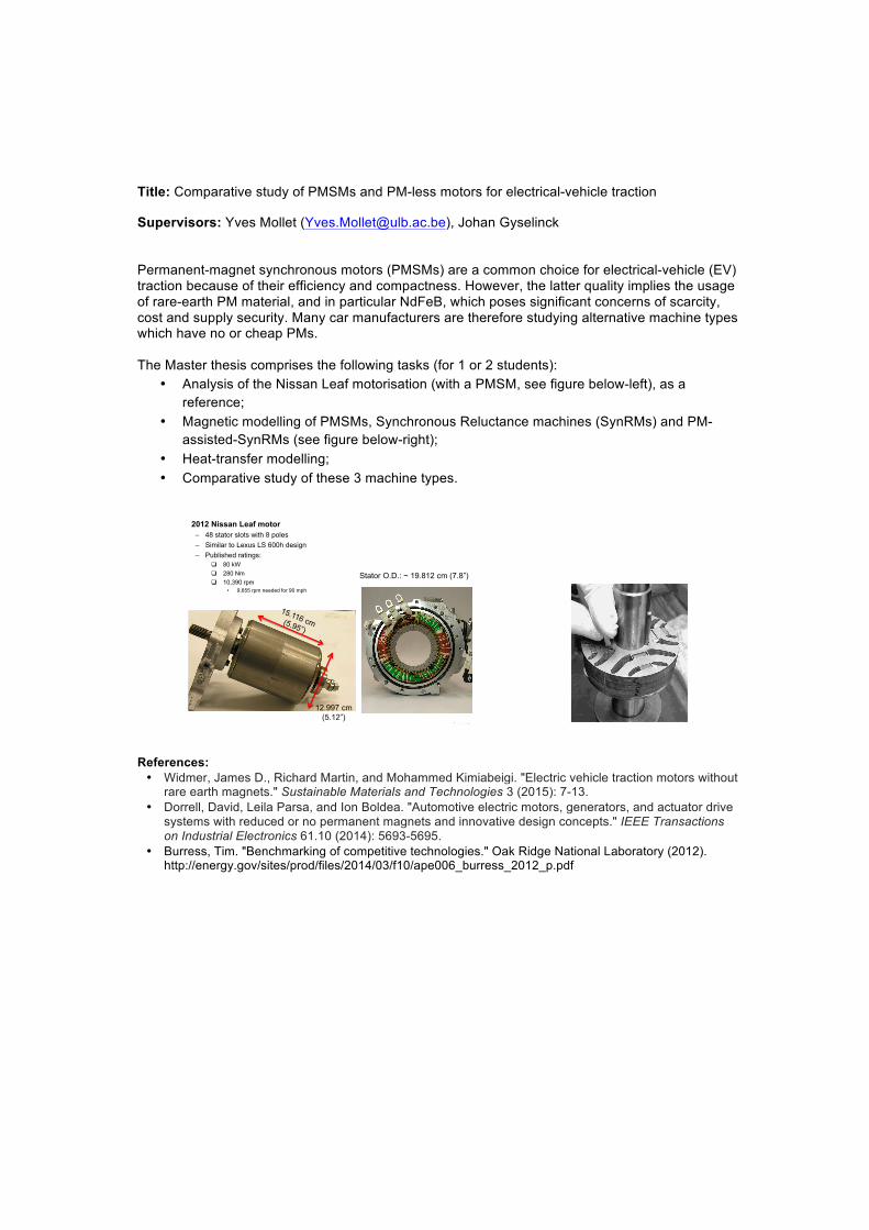
• Analysis of the Nissan Leaf motorisation (with a PMSM, see figure below-left), as a reference;
• Magnetic modelling of PMSMs, Synchronous Reluctance machines (SynRMs) and PM-assisted-SynRMs (see figure below-right);
• Heat-transfer modelling; • Comparative study of these 3 machine types.
References: • Widmer, James D., Richard Martin, and Mohammed Kimiabeigi. "Electric vehicle traction motors without
rare earth magnets." Sustainable Materials and Technologies 3 (2015): 7-13. • Dorrell, David, Leila Parsa, and Ion Boldea. "Automotive electric motors, generators, and actuator drive
systems with reduced or no permanent magnets and innovative design concepts." IEEE Transactions on Industrial Electronics 61.10 (2014): 5693-5695.
• Burress, Tim. "Benchmarking of competitive technologies." Oak Ridge National Laboratory (2012). http://energy.gov/sites/prod/files/2014/03/f10/ape006_burress_2012_p.pdf
Managed by UT-Battelle for the U.S. Department of Energy
Technical Accomplishments (16)
22
• 2012 Nissan Leaf motor – 48 stator slots with 8 poles
– Similar to Lexus LS 600h design
– Published ratings:
� 80 kW
� 280 Nm
� 10,390 rpm
• 9,655 rpm needed for 90 mph
12.997 cm
(5.12”)
Stator O.D.: ~ 19.812 cm (7.8”)
Siemens Industry Software nv Interleuvenlaan 68 Researchpark Haasrode Z1 B – 3001 Leuven [Belgium]
1
M a s t e r I n t e r n s h i p P r o p o s a l
Advanced prototyping for electrical vehicle components
Internship location: Siemens Industry Software NV, Leuven, Belgium
Supervisors: Ir. Ing. Mathieu Sarrazin ( [email protected] ); tel. : +32 16 384 484 Ing. Yves Mollet ( [email protected] ); tel.: +32 (0) 2 650 26 61
Internship duration: 4 to 6 months
Project summary:
It is clear that improved safety, faster development and better energy flow aspects become more and more critical in the different development stages of electrical vehicles (EV). At the moment, many driveline components were simply connected to each other without taken into account the real driving cycles of the E-vehicle or the interactions between the different components. Troubleshooting or even making big changes are quite difficult in a late development phase. Therefore, a closer analysis, assessment and optimization of the electrical drivetrain components need to happen already in an early development phase with Model-in-the-loop (Mil) and Hardware-in-the-loop (Hil) simulations. Hil simulations combine the real component with the virtual simulation world. In this way, available components can be tested in a realistic environment without an existing EV prototype. Multi-physical vehicle models (including thermal behaviour) are needed to support the Mil and Hil simulations. Test execution in such environment will finally support the improvement of the reliability of EV components, will give a better understanding of the system interactions before their integration on a system level and will speed up the development time. The student needs to i) become familiar with the topic and perform a literature study, ii) collect experimental data with our software/hardware platform, iii) develop accurate and robust MiL and HiL simulation models for EV components and iv) test and validate the developed models in a wide range of different operating conditions.
Project main objectives: § Gain skills on rapid prototyping and model based testing; § Gain skills on electrical machines. § Gain knowledge and practical testing skills
Candidate profile:
§ Master student in Applied Physics, Electrical and Mechanical Engineering § Skills in System, control and electrical machines § Hardware/software: Matlab/ Simulink § Be fluent in English (both oral and written) § have a problem-solving mind (take own initiative to solve a problem case)
Siemens Industry Software nv Interleuvenlaan 68 Researchpark Haasrode Z1 B – 3001 Leuven [Belgium]
1
M a s t e r I n t e r n s h i p P r o p o s a l
Electric signature diagnosis for critical production processes Internship location: Siemens Industry Software NV, Leuven, Belgium
Supervisors: Ir. Ing. Mathieu Sarrazin ( [email protected] ); tel. : +32 16 384 484 Ing. Yves Mollet ( [email protected] ); tel.: +32 (0) 2 650 26 61
Internship duration: 4 to 6 months
Project summary:
Condition monitoring plays an important role for the system reliability and safety in many manufacturing plants, especially for critical production process. A sudden failure in such a plant leads to a costly downtime, damage to neighboring equipment or even danger to humans. Smart automatic online failure detection and monitoring of drivetrains should avoid abnormal event progression and reduce productivity losses to help avoid major system breakdowns and catastrophes. Even, predicting the state of your machinery will provide better allocation of maintenance timing which provide a more efficient production. Amongst all types of electromechanical machinery, induction motors (including load parts) are often used in production plants due to their robustness and high-efficiency but they are not infallible. Because of this reason, a deeper investigation is needed during its operational regime. The objective of this thesis work is to investigate and develop algorithms which are able to detect and diagnose as early as possible electrical and mechanical faults based on stator current measurements of an inverter driven induction machine. The effect of stator winding short circuit, broken rotor bar, inverter failure, phase unbalance, rotor eccentricity, bearing fault, shaft misalignment and load faults (mechanical unbalance, gearbox fault or general failure in the load part) should be investigated. Current spectra of both faulty and healthy condition should be evaluated in time and frequency domain. A literature study of motor current signature analysis (MCSA) will help the student to build the state-of-the-art in this domain. Data under different operational load and speed conditions need to be collected for healthy and faulty motors with a data acquisition system in order to develop the right algorithms.
Project main objectives: § Gain skills on electromechanical machines § Gain skills on condition monitoring § Gain skills on signature post-processing techniques § Gain knowledge and practical testing skills.
Candidate profile:
§ Master student in Electrical or Mechatronic Engineering § Skills in System, control and electrical machines § Hardware/software: Matlab/ Simulink § Be fluent in English (both oral and written) § have a problem-solving mind (take own initiative to solve a problem case)
Unrestricted
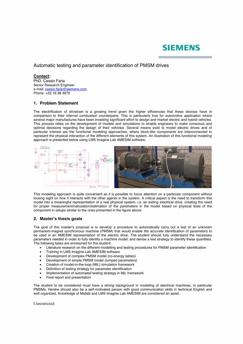
Automatic testing and parameter identification of PMSM drives Contact: PhD. Cassio Faria Senior Research Engineer e-mail: [email protected] Phone: +32 16 38 4670 1. Problem Statement The electrification of drivetrain is a growing trend given the higher efficiencies that these devices have in comparison to their internal combustion counterparts. This is particularly true for automotive application where several major manufactures have been investing significant effort to design and market electric and hybrid vehicles. This process relies on the development of models and simulations to enable engineers to make conscious and optimal decisions regarding the design of their vehicles. Several means exist to model electric drives and of particular interest are the functional modeling approaches, where block-like components are interconnected to represent the physical interaction of the different elements of this system. An illustration of this functional modeling approach is presented below using LMS Imagine.Lab AMESIM software.
This modeling approach is quite convenient as it is possible to focus attention on a particular component without loosing sight on how it interacts with the other agents in the system. A critical aspect is the need to transform this model into a meaningful representation of a real physical system, i.e. an exiting electrical drive, creating the need for proper measurement/calculation/estimation of the parameters in the model based on physical tests of the component in setups similar to the ones presented in the figure above. 2. Master’s thesis goals The goal of this master’s proposal is to develop a procedure to automatically carry out a test of an unknown permanent-magnet synchronous machine (PMSM) that would enable the accurate identification of parameters to be used in an AMESIM representation of the electric drive. The student should fully understand the necessary parameters needed in order to fully identify a machine model, and devise a test strategy to identify these quantities. The following tasks are envisioned for the student:
x Literature research on the different modelling and testing procedures for PMSM parameter identification x Training in LMS Imagine.Lab AMESIM software x Development of complex PMSM model (co-energy tables) x Development of simple PMSM model (lumped parameters) x Creation of model-in-the-loop (MiL) simulation framework x Definition of testing strategy for parameter identification x Implementation of automated testing strategy in MiL framework x Final report and presentation
The student to be considered must have a strong background in modeling of electrical machines, in particular PMSMs. He/she should also be a self-motivated person with good communication skills in technical English and well organized. Knowledge of Matlab and LMS Imagine.Lab AMESIM are considered an asset.
Unrestricted
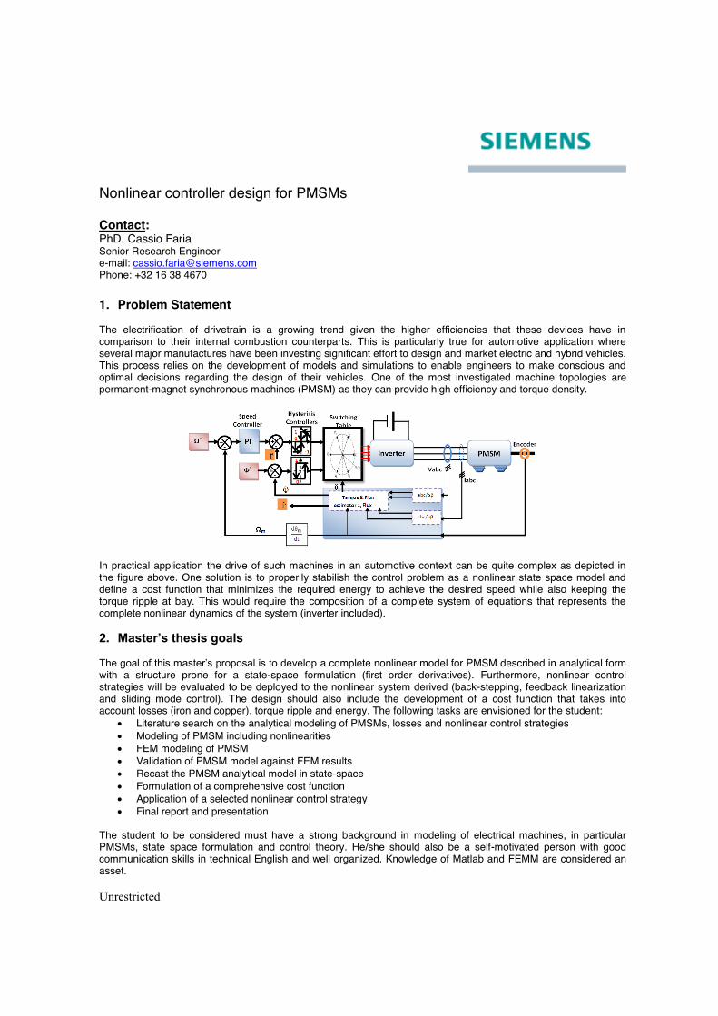
Nonlinear controller design for PMSMs Contact: PhD. Cassio Faria Senior Research Engineer e-mail: [email protected] Phone: +32 16 38 4670 1. Problem Statement The electrification of drivetrain is a growing trend given the higher efficiencies that these devices have in comparison to their internal combustion counterparts. This is particularly true for automotive application where several major manufactures have been investing significant effort to design and market electric and hybrid vehicles. This process relies on the development of models and simulations to enable engineers to make conscious and optimal decisions regarding the design of their vehicles. One of the most investigated machine topologies are permanent-magnet synchronous machines (PMSM) as they can provide high efficiency and torque density.
In practical application the drive of such machines in an automotive context can be quite complex as depicted in the figure above. One solution is to properlly stabilish the control problem as a nonlinear state space model and define a cost function that minimizes the required energy to achieve the desired speed while also keeping the torque ripple at bay. This would require the composition of a complete system of equations that represents the complete nonlinear dynamics of the system (inverter included). 2. Master’s thesis goals The goal of this master’s proposal is to develop a complete nonlinear model for PMSM described in analytical form with a structure prone for a state-space formulation (first order derivatives). Furthermore, nonlinear control strategies will be evaluated to be deployed to the nonlinear system derived (back-stepping, feedback linearization and sliding mode control). The design should also include the development of a cost function that takes into account losses (iron and copper), torque ripple and energy. The following tasks are envisioned for the student:
x Literature search on the analytical modeling of PMSMs, losses and nonlinear control strategies x Modeling of PMSM including nonlinearities x FEM modeling of PMSM x Validation of PMSM model against FEM results x Recast the PMSM analytical model in state-space x Formulation of a comprehensive cost function x Application of a selected nonlinear control strategy x Final report and presentation
The student to be considered must have a strong background in modeling of electrical machines, in particular PMSMs, state space formulation and control theory. He/she should also be a self-motivated person with good communication skills in technical English and well organized. Knowledge of Matlab and FEMM are considered an asset.
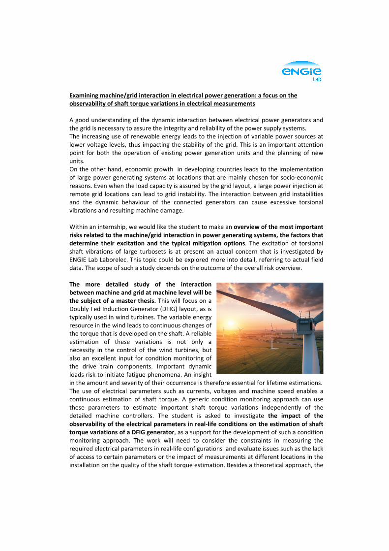
Examiningmachine/gridinteractioninelectricalpowergeneration:afocusontheobservabilityofshafttorquevariationsinelectricalmeasurementsAgoodunderstandingofthedynamicinteractionbetweenelectricalpowergeneratorsandthegridisnecessarytoassuretheintegrityandreliabilityofthepowersupplysystems.Theincreasinguseofrenewableenergyleadstotheinjectionofvariablepowersourcesatlowervoltage levels,thus impactingthestabilityofthegrid.This isan importantattentionpoint for both the operation of existing power generation units and the planning of newunits.Ontheotherhand,economicgrowthindevelopingcountriesleadstotheimplementationof largepowergenerating systemsat locations thataremainly chosen for socio-economicreasons.Evenwhentheloadcapacityisassuredbythegridlayout,alargepowerinjectionatremotegrid locationscan lead togrid instability.The interactionbetweengrid instabilitiesand the dynamic behaviour of the connected generators can cause excessive torsionalvibrationsandresultingmachinedamage.Withinaninternship,wewouldlikethestudenttomakeanoverviewofthemostimportantrisksrelatedtothemachine/gridinteractioninpowergeneratingsystems,thefactorsthatdetermine their excitation and the typicalmitigationoptions. The excitation of torsionalshaft vibrations of large turbosets is at present an actual concern that is investigated byENGIELabLaborelec.Thistopiccouldbeexploredmoreintodetail,referringtoactualfielddata.Thescopeofsuchastudydependsontheoutcomeoftheoverallriskoverview.The more detailed study of the interactionbetweenmachineandgridatmachinelevelwillbethesubjectofamasterthesis.ThiswillfocusonaDoublyFedInductionGenerator(DFIG)layout,asistypicallyusedinwindturbines.Thevariableenergyresourceinthewindleadstocontinuouschangesofthetorquethatisdevelopedontheshaft.Areliableestimation of these variations is not only anecessity in the control of the wind turbines, butalsoanexcellent input forconditionmonitoringofthe drive train components. Important dynamicloadsrisktoinitiatefatiguephenomena.Aninsightintheamountandseverityoftheiroccurrenceisthereforeessentialforlifetimeestimations.The use of electrical parameters such as currents, voltages andmachine speed enables acontinuous estimation of shaft torque. A generic condition monitoring approach can usethese parameters to estimate important shaft torque variations independently of thedetailed machine controllers. The student is asked to investigate the impact of theobservabilityoftheelectricalparametersinreal-lifeconditionsontheestimationofshafttorquevariationsofaDFIGgenerator,asasupportforthedevelopmentofsuchaconditionmonitoring approach. The work will need to consider the constraints in measuring therequiredelectricalparametersinreal-lifeconfigurationsandevaluateissuessuchasthelackofaccesstocertainparametersortheimpactofmeasurementsatdifferentlocationsintheinstallationonthequalityoftheshafttorqueestimation.Besidesatheoreticalapproach,the

workwillrelyonatestprogramonatestbenchandacomparisonwithactualfielddata.Thework will result in a sensitivity analysis of the different input parameters and set theboundaryguidelinesforaworkablefieldapproachforconditionmonitoring.AboutENGIELabLaborelec(www.laborelec.com)ENGIELabLaborelecisaleadingexpertiseandresearchcentrethatisactiveinthedomainsofgeneration,transmission,distribution,storageandfinaluseofelectricalenergy.Itsmainshareholders are ENGIE and independent gridoperators. Laborelechas a global presence,withactivitiesinmorethan60countriesandofficesinBelgium,theNetherlands,Germany,ChileandAbuDhabi.Mostofour240specialisedengineersandtechniciansworkfromourmainofficesinLinkebeek,Belgium.Contactperson:KoenDeBauw([email protected],tel.+3223820575)
INTERNSHIP + MASTER THESIS Traction Department – Control Command
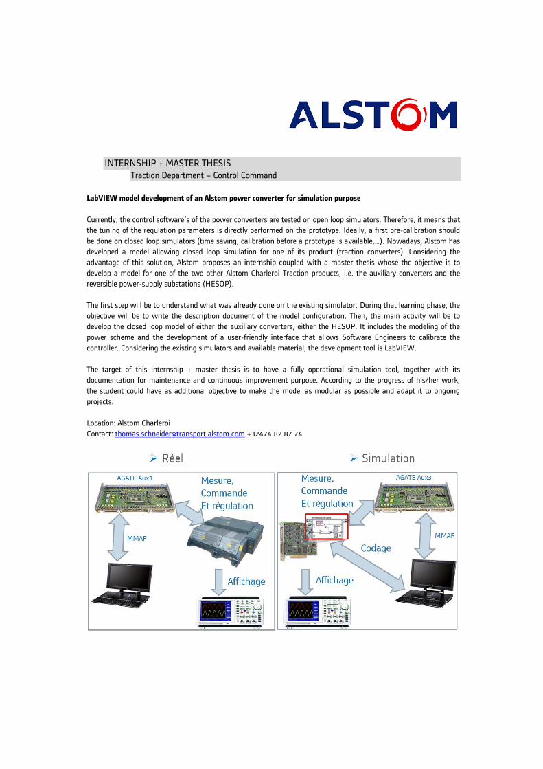
LabVIEW model development of an Alstom power converter for simulation purpose
Currently, the control software’s of the power converters are tested on open loop simulators. Therefore, it means that
the tuning of the regulation parameters is directly performed on the prototype. Ideally, a first pre-calibration should
be done on closed loop simulators (time saving, calibration before a prototype is available,…). Nowadays, Alstom has
developed a model allowing closed loop simulation for one of its product (traction converters). Considering the
advantage of this solution, Alstom proposes an internship coupled with a master thesis whose the objective is to
develop a model for one of the two other Alstom Charleroi Traction products, i.e. the auxiliary converters and the
reversible power-supply substations (HESOP).
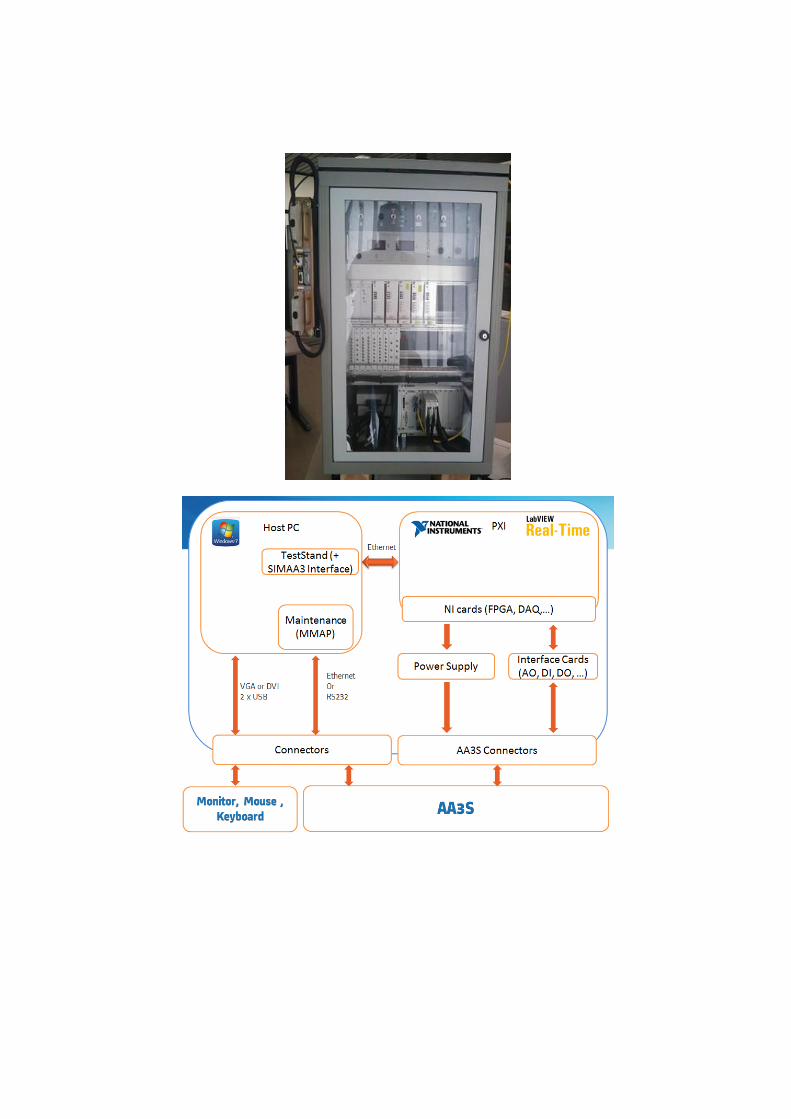
The first step will be to understand what was already done on the existing simulator. During that learning phase, the
objective will be to write the description document of the model configuration. Then, the main activity will be to
develop the closed loop model of either the auxiliary converters, either the HESOP. It includes the modeling of the
power scheme and the development of a user-friendly interface that allows Software Engineers to calibrate the
controller. Considering the existing simulators and available material, the development tool is LabVIEW.
The target of this internship + master thesis is to have a fully operational simulation tool, together with its
documentation for maintenance and continuous improvement purpose. According to the progress of his/her work,
the student could have as additional objective to make the model as modular as possible and adapt it to ongoing
projects.
Location: Alstom Charleroi
Contact: [email protected] +32474 82 87 74
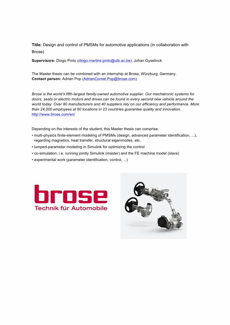
Title: Design and control of PMSMs for automotive applications (in collaboration with
Brose)
Supervisors: Diogo Pinto ([email protected]), Johan Gyselinck The Master thesis can be combined with an internship at Brose, Würzburg, Germany. Contact person: Adrian Pop ([email protected]) Brose is the world’s fifth-largest family-owned automotive supplier. Our mechatronic systems for doors, seats or electric motors and drives can be found in every second new vehicle around the world today. Over 80 manufacturers and 40 suppliers rely on our efficiency and performance. More than 24,000 employees at 60 locations in 23 countries guarantee quality and innovation. http://www.brose.com/en/ Depending on the interests of the student, this Master thesis can comprise:
• multi-physics finite-element modeling of PMSMs (design, advanced parameter identification, ...), regarding magnetics, heat transfer, structural eigenmodes, etc.
• lumped-parameter modeling in Simulink for optimizing the control
• co-simulation, i.e. running jointly Simulink (master) and the FE machine model (slave)
• experimental work (parameter identification, control, ...)
Title: Design and control of PMSMs for automotive applications (in collaboration with Brose) Supervisor: Yves MOLLET ([email protected]) Details:
ThiscanbecombinedwithaninternshipatBrose,Wurzburg,Germany.
Contactperson:AdrianPop([email protected])
Broseistheworld’sfifth-largestfamily-ownedautomotivesupplier.Ourmechatronicsystemsfordoors,seatsorelectricmotorsanddrivescanbefoundineverysecondnewvehiclearoundtheworldtoday.Over80manufacturersand40suppliersrelyonourefficiencyandperformance.Morethan24,000employeesat60locationsin23countriesguaranteequalityandinnovation.http://www.brose.com/en/
ThesemechatronicsystemsareoftenequippedwithbrushedDCmotorsorPermanent-MagnetSynchronousMotors(PMSMs).
Dependingontheinterestsofthestudent,thisMasterthesiscancomprise
• finite-elementmodelingofPMSMs(design,advancedparameteridentification,…)• lumped-parametermodelinginSimulinkforoptimizingthecontrol• co-simulation,i.e.runningjointlySimulink(master)andtheFEmachinemodel(slave)• experimentalwork(parameteridentification,control,…)
© 2017, Thales Alenia Space
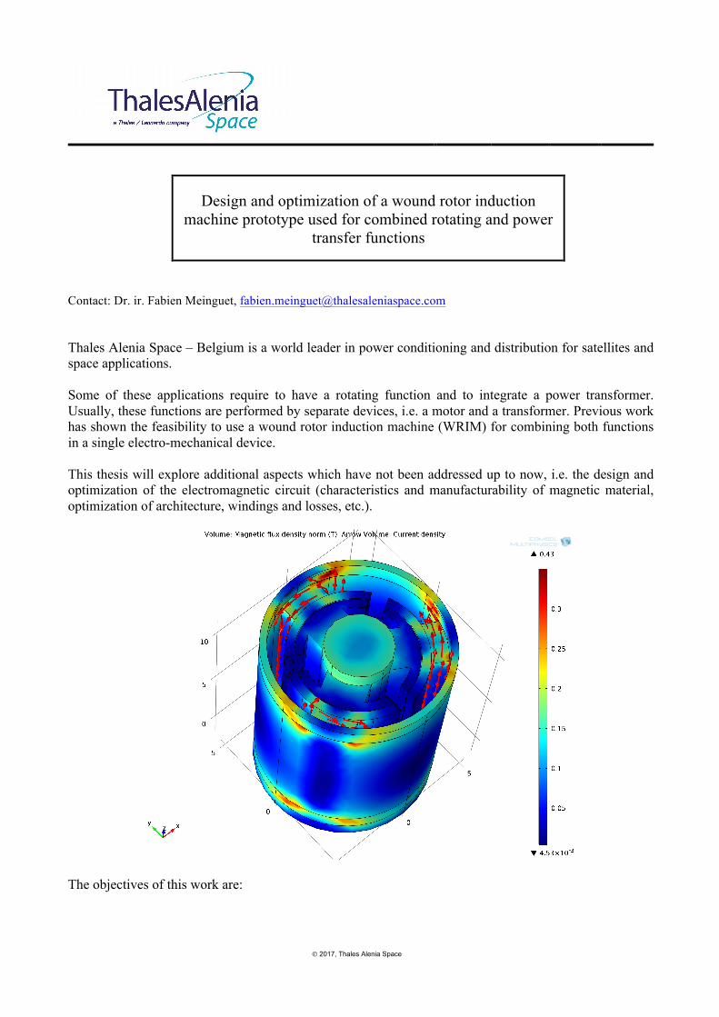
Design and optimization of a wound rotor induction
machine prototype used for combined rotating and power transfer functions
Contact: Dr. ir. Fabien Meinguet, [email protected] Thales Alenia Space – Belgium is a world leader in power conditioning and distribution for satellites and space applications. Some of these applications require to have a rotating function and to integrate a power transformer. Usually, these functions are performed by separate devices, i.e. a motor and a transformer. Previous work has shown the feasibility to use a wound rotor induction machine (WRIM) for combining both functions in a single electro-mechanical device. This thesis will explore additional aspects which have not been addressed up to now, i.e. the design and optimization of the electromagnetic circuit (characteristics and manufacturability of magnetic material, optimization of architecture, windings and losses, etc.).
The objectives of this work are:
© 2017, Thales Alenia Space
• provide a state-of-the-art of magnetic material fitting the application; • analytical and finite element modelling of the WRIM prototype; • optimization of the WRIM design for given specifications; • (manufacturing and test of a WRIM prototype) (*)
Required skills:
• good understanding of electric machines and magnetic transformers; • knowledge of finite element software (FEMM, COMSOL) is an advantage; • motivation and autonomy.
(*) Note: possibility of internship and master thesis on this topic. A prototype can only be considered in case of combined internship and master thesis

© 2017, Thales Alenia Space
Modelling and characterization of magnetics
used for power conversion
Contact: Dr. ir. Fabien Meinguet, [email protected] Thales Alenia Space – Belgium is a world leader in power conditioning and distribution for satellites and space applications. In power conversion, magnetic components such as transformers and/or inductors are mandatory. In high-frequency power conversion, the transformer/inductor modelling can be quite complex since the parasitic elements (parasitic capacitance between windings, between windings and structure, leakage inductance,…) and skin and proximity effects have a significant impact on the final power converter design (additional dissipation, reduced performances, design of surrounding EMC filters,…).
In a constant effort to reduce the mass, losses, cost of these devices and also to simplify the manufacturing of these elements, TAS-B has recently designed a transformer and inductors with 3D-printed support used for the windings (see above).
© 2017, Thales Alenia Space
In this project, a study of these elements is proposed with the following approach:
• Finite element modelling of the magnetics under study; o Electrical modelling, including parasitic elements; o Thermal modelling;
• Derivation of a Spice / µCap model of the components (electrical and equivalent thermal model); • Validation by tests on the existing prototypes (thermal and electrical);
Required skills:
• Good understanding of Maxwell laws; • knowledge of finite element software (FEMM, COMSOL) and/or electrical simulator (PSpsice, µCap) is an advantage;
• practical skills for tests; • motivation.
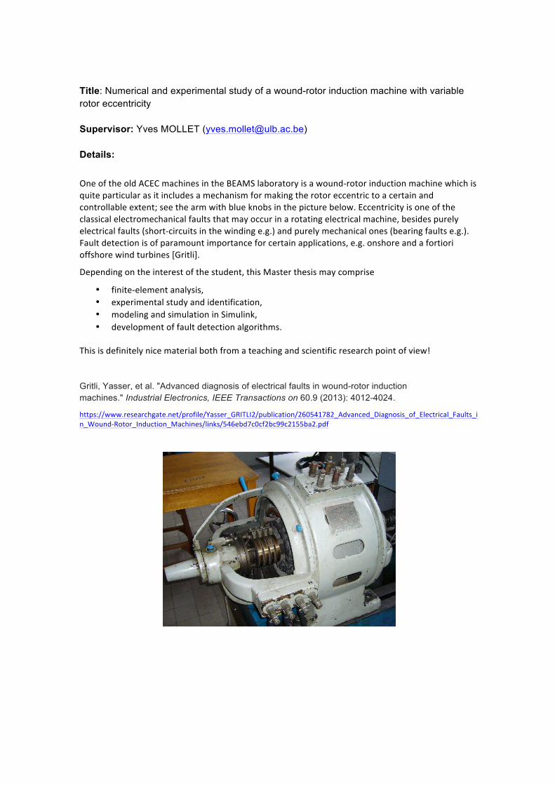
Title: Numerical and experimental study of a wound-rotor induction machine with variable rotor eccentricity Supervisor: Yves MOLLET ([email protected]) Details:
OneoftheoldACECmachinesintheBEAMSlaboratoryisawound-rotorinductionmachinewhichisquiteparticularasitincludesamechanismformakingtherotoreccentrictoacertainandcontrollableextent;seethearmwithblueknobsinthepicturebelow.Eccentricityisoneoftheclassicalelectromechanicalfaultsthatmayoccurinarotatingelectricalmachine,besidespurelyelectricalfaults(short-circuitsinthewindinge.g.)andpurelymechanicalones(bearingfaultse.g.).Faultdetectionisofparamountimportanceforcertainapplications,e.g.onshoreandafortiorioffshorewindturbines[Gritli].
Dependingontheinterestofthestudent,thisMasterthesismaycomprise
• finite-elementanalysis,• experimentalstudyandidentification,• modelingandsimulationinSimulink,• developmentoffaultdetectionalgorithms.
Thisisdefinitelynicematerialbothfromateachingandscientificresearchpointofview!
Gritli, Yasser, et al. "Advanced diagnosis of electrical faults in wound-rotor induction machines." Industrial Electronics, IEEE Transactions on 60.9 (2013): 4012-4024.
https://www.researchgate.net/profile/Yasser_GRITLI2/publication/260541782_Advanced_Diagnosis_of_Electrical_Faults_in_Wound-Rotor_Induction_Machines/links/546ebd7c0cf2bc99c2155ba2.pdf