Embed Size (px)
Citation preview

HAL Id: hal-02319930https://hal.archives-ouvertes.fr/hal-02319930
Submitted on 18 Oct 2019
HAL is a multi-disciplinary open accessarchive for the deposit and dissemination of sci-entific research documents, whether they are pub-lished or not. The documents may come fromteaching and research institutions in France orabroad, or from public or private research centers.
L’archive ouverte pluridisciplinaire HAL, estdestinée au dépôt et à la diffusion de documentsscientifiques de niveau recherche, publiés ou non,émanant des établissements d’enseignement et derecherche français ou étrangers, des laboratoirespublics ou privés.
Massively Parallel Implementation of FETI-2LMMethods for the Simulation of the Sparse ReceivingArray Evolution of the GRAVES Radar System for
Space Surveillance and TrackingAntoine Jouadé, André Barka
To cite this version:Antoine Jouadé, André Barka. Massively Parallel Implementation of FETI-2LM Methods for the Sim-ulation of the Sparse Receiving Array Evolution of the GRAVES Radar System for Space Surveillanceand Tracking. IEEE Access, IEEE, 2019, 7, pp.128968-128979. �10.1109/ACCESS.2019.2938011�.�hal-02319930�

SPECIAL SECTION ON WIDE AREA SURVEILLANCE
Received July 30, 2019, accepted August 16, 2019, date of publication August 28, 2019, date of current version September 23, 2019.
Digital Object Identifier 10.1109/ACCESS.2019.2938011
Massively Parallel Implementation of FETI-2LMMethods for the Simulation of the SparseReceiving Array Evolution of theGRAVES Radar System for SpaceSurveillance and TrackingANTOINE JOUADÉ AND ANDRÉ BARKAONERA/DEMR, Université de Toulouse, 31055 Toulouse, France
Corresponding authors: Antoine Jouadé ([email protected]) and André Barka ([email protected])
This work was supported in part by the French Defense Procurement Agency [Direction Générale de l’Armement (DGA)] through thecontract for the GRAVES refurbishment and upgrades with a partial EU SST Program, and in part by the Grand Equipement National deCalcul Intensif (GENCI) Grant c2014109083.
ABSTRACT This paper presents the massively parallel implementation of the FETI-2LM techniques (FiniteElement Tearing and Interconnecting with two Lagrange Multipliers) in the FACTOPO code to solve large-scale sparse receiving array evolutions of the GRAVES bistatic radar in the VHF band. There are four mainingredients in the proposed work and methodology: 1) the implementation of a total field weak formulationof FETI-2LM algorithms for multi-sources modeling using an efficient block Krylov recycling strategyfor the calculation of the hundreds of antenna embedded radiation patterns of the sparse array; 2) theimplementation of a meshing strategy consisting in generating the sparse array by populating a regularperiodic grid; 3) the implementation of the proposed methodology on massively parallel clusters; 4) theinvestigation of performances of the optimized GRAVES elementary antenna in the VHF band, followed bythe demonstration of the expected gain performances evenwith stronger interferences due to the densificationof the array. These simulations of the GRAVES sparse array requiring the resolution of sparse linear systemswith 10.47 billion unknowns have been made possible thanks to recent developments of the FETI-2LMdomain decomposition method and the use of 13, 692 Intel Xeon Broadwell E5-2680v4 computing cores.A total of 3.8 million cumulated hours have been invested in the interest of the augmentation of theantennas. Until now FETI-2LM methods have been successfully implemented for antenna and diffractionelectromagnetic simulations in the S-C-X-Ku and Ka bands and to the best to our knowledge this is the firsttime that they have been used in the VHF band.
INDEX TERMS Aerospace control, bi-static radar, Doppler radar, digital beamforming, low earth orbitsatellites, parallel machines, supercomputers, radar tracking, real-time systems, space surveillance andtracking, sparse array, very-high frequencies, wide area surveillance, finite element methods, finite elementtearing and interconnecting, FETI, domain decomposition methods, VHF band, FACTOPO.
I. INTRODUCTIONThe GRAVES System (Grand Réseau Adapté à la VEilleSpatiale = Large Radar Array for Space Surveillance) [1]is a Space Surveillance and Tracking (SST) system [2]–[4],
The associate editor coordinating the review of this article and approvingit for publication was Mehmet Alper Uslu.
whose main mission is to construct a space picture for mil-itary intelligence by autonomously building and maintain-ing a catalog of space objects. GRAVES is owned by theFrench Ministry for the Armed Forces, and is operated by theFrench Air and Space Force. Its performances have enabledover 300 objects in Low Earth Orbit (LEO) to be detectedand catalogued. The GRAVES system is a bistatic radar
128968 This work is licensed under a Creative Commons Attribution 4.0 License. For more information, see http://creativecommons.org/licenses/by/4.0/ VOLUME 7, 2019

A. Jouadé, R. Barka: Massively Parallel Implementation of FETI-2LM Methods
FIGURE 1. Illustration of the principle of the GRAVES bistatic radar withE: Emitter and R: Receiver.
(see Figure 1) working with a VHF continuous wave purecarrier transmission at 143.05 MHz. The transmission sitecorresponds to four linearly polarized transmitting arrays,each covering 45◦ in azimuth and 30◦ in elevation. EachField-of-View (FoV) is individually scanned by electronicdeflection forming a fence in the sky. A coverage of 180◦
in azimuth allows the detection of each satellite at leastonce every 24 hours. The reception site, shown in Figure2,400 km south of the transmission site (to ensure a gooddecoupling and to avoid saturating the reception stages), is a60 m diameter sparse array of circularly-polarized antennaelements [1] that receives the signals reflected by the Low
Earth orbiting objects crossing the FoV. Circular polarizationallows arbitrary linearly-polarized signals influenced by theionosphere due to the Faraday effect to be received.
The digital beamforming (DBF) performed at the receptionlevel enables the localization of the objects along the azimuthand the elevation, while the frequency shift caused by theDoppler effect enables the radial velocity, and hence theorbit altitude, to be determined. There are few equivalentsto the GRAVES radar strictly designed for space surveil-lance, and we can cite the following works and achievementsdescribed in References [5]–[7]. Other functional equivalentsof large surveillance radars designed for advanced alert areAmerican [8] or Russian [9]; they contribute to space surveil-lance but are not sized to this mission. There are no functionalequivalents in Europe; GRAVES is the only way system ableto do so, leading France to be among the only 4 nations withthis ability to monitor and autonomously build a catalog ofspace objects. GRAVES is a unique and original concept,which is its strength. ONERA, associated with the SMEDegréane Horizon, has been notified by the DGA, the FrenchDefense Procurement Agency, for the refurbishment contractaimed at extending the life time of the system up to 2030,while improving the overall performance in order to detectsmaller objects (cubsat satellites and space debris) over greatdistances. The lifetime extension involves updating the trans-mission and reception systems as well as the processingchain. The performance enhancements that are of interest inthis article are the receiving antenna element performanceimprovement and the densification of the receiving array by
FIGURE 2. Photography of the sparse receiving array.
VOLUME 7, 2019 128969
A. Jouadé, R. Barka: Massively Parallel Implementation of FETI-2LM Methods
investigating, through full-wave electromagnetic simulation,the coupling effects of a more populated sparse array onthe overall array performance. These investigations wouldhave a positive impact on the overall link budget, enablingnew objects to be detected and catalogued. The foreseenevolutions would make GRAVES an even more valuable keycontributor to the SST segment.
In the field of electromagnetic simulation, it is now wellestablished that the Finite Element Method (FEM) is oneof the most successful frequency domain computationalmethods [10]. The method is now intensely implementedby engineers and designers often interested in full-wavecomputation of complete systems, and of their possibleenvironments [10]–[12]. These methods are now widelyspread through commercial software such as CSTMicrowaveStudio [13] and HFSS [14]. Such simulations can be verycomplex, especially when the problems of interest involvemulti-scale geometries with very fine features. The FEMcombines, very efficiently, a geometrical adaptability andability to handle arbitrary materials for modeling complexgeometries and materials of arbitrary composition, includingmeta-materials currently intensely used in modern antennas.Finite element approximation of Maxwell’s equations leadsto a sparse linear system, usually solved by using director iterative solvers. However, modern engineering applica-tions dealing with antennas, scatterers or microwave circuits,require the solution of problems with billions of unknowns.In order to efficiently simulate complex electromagneticproblems of large size compared to the wavelength, multido-main and multimethod coupling schemes based on general-ized scatteringmatrix computations of 3-D sub-domains havebeen developed [15] and implemented for antenna siting [12],[16], [17] as well as diffraction problems [18]. The globaltarget is split into sub-domains separated by fictitious sur-faces. For each sub-domain (even the exterior 3-D volume),the Generalized Scattering Matrix (GSM) is computed withdifferent methods such as the FEM, the Electric Field Inte-gral Equation (EFIE) or the Combined Field Integral Equa-tion (CFIE) combined with a generalized field expansion onthe fictitious surfaces with spectral basis functions [17] ormodal basis functions [15]. Then, the different objects areconnected together by cascading the various matrices. Withina context of parametric investigations, the scattering matricesof the modified domains have to be re-evaluated, the othersare simply re-used in the connection step. This strategy signif-icantly reduces the computation time compared to traditionalhybrid methods for which a geometric or electromagneticmodification requires a new computation of the completetarget. Furthermore, the matrix computations are totally inde-pendent, allowing code and data protection within the contextof industrial consortium projects. This GSM-based strategyhas been enriched with asymptotic Physical Optics (PO)techniques [19] but is, however, quite difficult to implementfor the GRAVES reception array and was not retained.
We preferred to implement some recent advances inDomain Decomposition Methods (DDM), especially the
Finite Element Tearing and Interconnecting with twoLagrange multipliers (FETI-2LM) technique, to solve large-scale FEM problems with multiple right-hand sides encoun-tered in electromagnetic applications (up to several hundredsof embedded antennas in the GRAVES project). DDMswere initially developed for the efficient parallel solutionof elliptic problems and are based on consistent enforce-ment of the Dirichlet boundary conditions at the inter-face, by using the Schur complement method [20], or byusing Neumann boundary conditions at the interface, as inthe FETI method [21]. The FETI method was extended tothe solution of Helmholtz equations using Robin interfaceboundary conditions, which led to the FETI-H method [22],and which is based on the early work of [23]. For theHelmholtz equations, the FETI-Hmethod has been efficientlyimproved for multiple right-hand sides with recycling Krylovmethods [24], [25]. FETI methods have been successfullyextended to the solution of Maxwell equations (FETI-2LM)in the frequency domain for the calculation of antenna arraysand metamaterial periodic structures [26], [27] and equippedwith recycling Krylov methods [28], [29] to speed-upmulti-source applications.
The first particularity of this work is the implementation ofKrylov type iterative algorithms (recently proposed in [30]),in order to improve the FETI-2LM domain decompositionmethod to solve multi-source electromagnetic problems. Thisis very attractive in the GRAVES context, where we haveto calculate the embedded radiation patterns of hundreds ofantennas before performing the digital beamforming (DBF)at the reception level. The principle is to store all searchdirection vectors for the condensed interface problems arisingfrom the successive sources (elementary antennas) and touse them to build a projection that decreases the numberof iterations for the successive sequences of Krylov itera-tions. The first algorithm is based on a projection techniqueand the second combines the projection technique with ablock strategy consisting in simultaneously computing sev-eral blocks of search directions for several right-hand sides.It has been shown in [30], through the solution of two engi-neering applications, that both methods can greatly reducethe number of iterations for convergence by increasing thememory used for recycling the Krylov vectors. For scatter-ing applications and plane wave illuminations, it has beenobserved that the projection strategy allows a drastic reduc-tion of the number of iterations from the second incidence.The block strategy not only reduces the number of iterationsfor the successive sources, but also enhances the parallel effi-ciency of the FETI-2LM method. This feature is particularlybeneficial for the computation of the radiation efficiency of anantenna array (scattering parameters and embedded radiationpatterns). Indeed, unlike plane wave excitation, the localantenna feed with TEM ports provides very different nearfield solutions from one port to another. It has been shownin [30], on antenna arrays that the computation for few lin-early independent right-hand sides with the block strategyoffers a speed increase of 11.17. This FETI-2LM method
128970 VOLUME 7, 2019
A. Jouadé, R. Barka: Massively Parallel Implementation of FETI-2LM Methods
implemented in ONERA’s FACTOPO code has also beenrecently optimized for the simulation of non-periodic andmulti-scale transmit-arrays [31], and is therefore naturallypreferred for the simulation of the hundreds of antennaspopulating the GRAVES receiving sparse array.
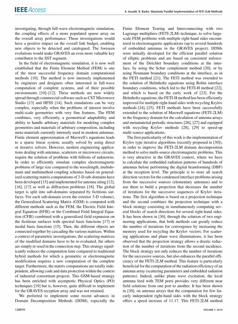
FIGURE 3. Subdomain decomposition of the densified GRAVE sparsereceiving array.
The second particularity of our implementation ofthe Finite Element Tearing and Interconnecting method isthe fact that the complete mesh is not built upstream of theresolution of the electromagnetic problem and, consequently,a specific mesh splitter tool such as METIS [32] is not neces-sary to decompose the large-scale initial mesh (60m diameterdisk) into sub-domains, as was done, for example, for arrayantennas covered by a radome in [33]. Our method is gen-eral, based on parallel-thinking, and tailored to efficientlyintroduce 3D non-periodic grids with sub-domains that arenot necessarily of the same size (VHF antenna, ground planecells and empty sub-domains described in Figure 3). Eachsub-domain in our decomposition is equipped with its ownlocal mesh, belonging to a limited set of unit-cell meshes,generated separately with an automatic procedure of the GIDpreprocessor [34]. Thus, the geometry of very complex sparsearray antennas is represented efficiently with only a few localmeshes (three for GRAVES arrays). Furthermore, since themethod is implemented on parallel machines, each computecore with at least 4 GB of memory is allocated exclusively toa sub-domain (elementary cell of the sparse array). One caneasily implement relatively fine meshes in each sub-domain,rendering the sometimes very slow adaptive mesh refinementtechniques unnecessary.
The third particularity of this work is the simulation onmassively parallel clusters using MPI programming of twoGRAVES sparse arrays: the initial configuration and thedensified configuration. This kind of resources available atONERA is not farfetched, and is required for the demon-stration of the gain efficiency of the densified configurationsdespite the coupling and shadowing effects due to the VHFantennas.
The paper is organized as follows. Section II briefly recallsthe FETI-2LM formulation, proposes further developments totake into account, through a total field formulation, a waveg-uide mode excitation feeding the antenna with block Krylovmulti-source algorithms to speed-up the GRAVES embed-ded antenna diagram simulations. In Section III a methodis proposed and its accuracy for the discretization of thesparse array with three types of sub-domains (VHF antenna,empty and ground plane) is discussed. In Section IV, a recentoptimization of the unit-cell antenna is proposed followedin Section V by the demonstration of gain performancesobtained after densification of the sparse receiving array.
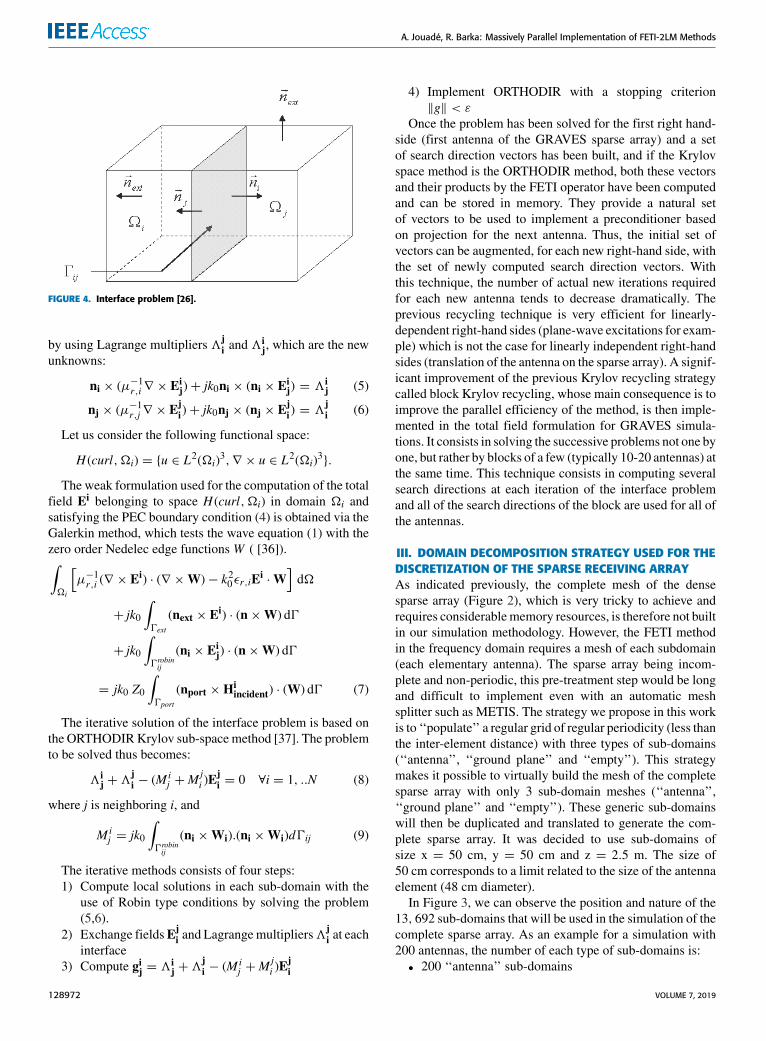
II. FETI-2LM FORMULATION (THEORICAL REMINDERS)The FETI-2LMmethod proposed to solve the Maxwell equa-tions [26], [27], [35], is based on the decomposition ofthe global computational domain in non-overlapping sub-domains (Figure 4), in which local solution fields are cal-culated by solving the finite-element system with a directmethod. Tangent field continuity is then imposed at theinterfaces by using 2 Lagrange multipliers, which leads to areduced problem at the interfaces that can be solved usingan iterative method. The solution of the interface problem isthen used as a boundary condition to evaluate the fields ineach sub-domain.
The Ampère-Maxwell Law and Faraday’s Law can becombined to yield a single-order vector wave equation.
We denote by � = �1 ∪�2 ∪ . . . ∪�N a partition of theinitial computation domain (Figure 4). In each sub-domain�i, the total electric and magnetic fields Ei, Hi satisfies:
∇ × (µ−1r,i∇ × Ei)− k20εr,iEi= 0 (1)
Vectors Eiincident andH
iincident stand for the modal incident
electric and magnetic field defined at the waveguide surface0port of a unit normal nport pointing inwards to volume �icontaining the modal source:
nport ×Hi= nport ×Hi
incident (2)
k0 = ω√ε0µ0 is the free-space wave number, εr,i is the
relative permittivity in �i and µr,i the relative permittivityin�i. 0ABC represents the boundary of the volume� and nextrepresents its exterior normal, along which the scattered fieldsatisfies absorbing boundary conditions (ABC):
next ×∇ × Eis + jk0next × (next × Ei
s) = 0 (3)
On perfectly electric conducting surfaces 0PEC , the totalelectric field verifies the usual Perfectly Electric Conduc-tor (PEC) boundary conditions:
next × Ei= 0 (4)
In the following, Eij is the electric field on the inter-
face of the sub-domain �i adjacent to the sub-domain �j(Figure 4). At interfaces 0robinij separating two sub-domains�i and �j, Robin type boundary conditions are imposed,
VOLUME 7, 2019 128971
A. Jouadé, R. Barka: Massively Parallel Implementation of FETI-2LM Methods
FIGURE 4. Interface problem [26].
by using Lagrange multipliers 3ji and 3
ij, which are the new
unknowns:
ni × (µ−1r,i∇ × Eij)+ jk0ni × (ni × Ei
j) = 3ij (5)
nj × (µ−1r,j∇ × Eji)+ jk0nj × (nj × Ej
i) = 3ji (6)
Let us consider the following functional space:
H (curl, �i) = {u ∈ L2(�i)3,∇ × u ∈ L2(�i)3}.
The weak formulation used for the computation of the totalfield Ei belonging to space H (curl, �i) in domain �i andsatisfying the PEC boundary condition (4) is obtained via theGalerkin method, which tests the wave equation (1) with thezero order Nedelec edge functionsW ( [36]).∫�i
[µ−1r,i (∇ × Ei) · (∇ ×W)− k20εr,iE
i·W
]d�
+ jk0
∫0ext
(next × Ei) · (n×W) d0
+ jk0
∫0robinij
(ni × Eij) · (n×W) d0
= jk0 Z0
∫0port
(nport ×Hiincident) · (W) d0 (7)
The iterative solution of the interface problem is based onthe ORTHODIRKrylov sub-space method [37]. The problemto be solved thus becomes:
3ij +3
ji − (M i
j +Mji )E
ji = 0 ∀i = 1, ..N (8)
where j is neighboring i, and
M ij = jk0
∫0robinij
(ni ×Wi).(ni ×Wi)d0ij (9)
The iterative methods consists of four steps:1) Compute local solutions in each sub-domain with the
use of Robin type conditions by solving the problem(5,6).
2) Exchange fieldsEji and Lagrangemultipliers3j
i at eachinterface
3) Compute gij = 3ij +3
ji − (M i
j +Mji )E
ji
4) Implement ORTHODIR with a stopping criterion‖g‖ < ε
Once the problem has been solved for the first right hand-side (first antenna of the GRAVES sparse array) and a setof search direction vectors has been built, and if the Krylovspace method is the ORTHODIR method, both these vectorsand their products by the FETI operator have been computedand can be stored in memory. They provide a natural setof vectors to be used to implement a preconditioner basedon projection for the next antenna. Thus, the initial set ofvectors can be augmented, for each new right-hand side, withthe set of newly computed search direction vectors. Withthis technique, the number of actual new iterations requiredfor each new antenna tends to decrease dramatically. Theprevious recycling technique is very efficient for linearly-dependent right-hand sides (plane-wave excitations for exam-ple) which is not the case for linearly independent right-handsides (translation of the antenna on the sparse array). A signif-icant improvement of the previous Krylov recycling strategycalled block Krylov recycling, whose main consequence is toimprove the parallel efficiency of the method, is then imple-mented in the total field formulation for GRAVES simula-tions. It consists in solving the successive problems not one byone, but rather by blocks of a few (typically 10-20 antennas) atthe same time. This technique consists in computing severalsearch directions at each iteration of the interface problemand all of the search directions of the block are used for all ofthe antennas.
III. DOMAIN DECOMPOSITION STRATEGY USED FOR THEDISCRETIZATION OF THE SPARSE RECEIVING ARRAYAs indicated previously, the complete mesh of the densesparse array (Figure 2), which is very tricky to achieve andrequires considerablememory resources, is therefore not builtin our simulation methodology. However, the FETI methodin the frequency domain requires a mesh of each subdomain(each elementary antenna). The sparse array being incom-plete and non-periodic, this pre-treatment step would be longand difficult to implement even with an automatic meshsplitter such as METIS. The strategy we propose in this workis to ‘‘populate’’ a regular grid of regular periodicity (less thanthe inter-element distance) with three types of sub-domains(‘‘antenna’’, ‘‘ground plane’’ and ‘‘empty’’). This strategymakes it possible to virtually build the mesh of the completesparse array with only 3 sub-domain meshes (‘‘antenna’’,‘‘ground plane’’ and ‘‘empty’’). These generic sub-domainswill then be duplicated and translated to generate the com-plete sparse array. It was decided to use sub-domains ofsize x = 50 cm, y = 50 cm and z = 2.5 m. The size of50 cm corresponds to a limit related to the size of the antennaelement (48 cm diameter).
In Figure 3, we can observe the position and nature of the13, 692 sub-domains that will be used in the simulation of thecomplete sparse array. As an example for a simulation with200 antennas, the number of each type of sub-domains is:• 200 ‘‘antenna’’ sub-domains
128972 VOLUME 7, 2019
A. Jouadé, R. Barka: Massively Parallel Implementation of FETI-2LM Methods
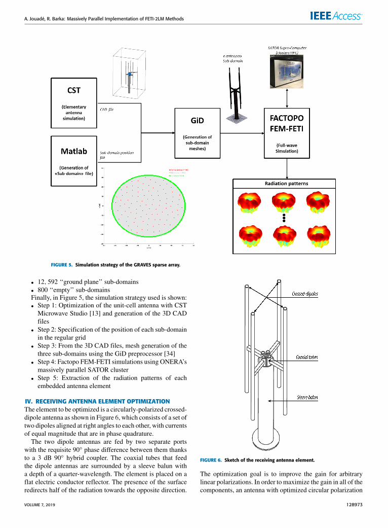
FIGURE 5. Simulation strategy of the GRAVES sparse array.
• 12, 592 ‘‘ground plane’’ sub-domains• 800 ‘‘empty’’ sub-domainsFinally, in Figure 5, the simulation strategy used is shown:• Step 1: Optimization of the unit-cell antenna with CSTMicrowave Studio [13] and generation of the 3D CADfiles
• Step 2: Specification of the position of each sub-domainin the regular grid
• Step 3: From the 3D CAD files, mesh generation of thethree sub-domains using the GiD preprocessor [34]
• Step 4: Factopo FEM-FETI simulations using ONERA’smassively parallel SATOR cluster
• Step 5: Extraction of the radiation patterns of eachembedded antenna element
IV. RECEIVING ANTENNA ELEMENT OPTIMIZATIONThe element to be optimized is a circularly-polarized crossed-dipole antenna as shown in Figure 6, which consists of a set oftwo dipoles aligned at right angles to each other, with currentsof equal magnitude that are in phase quadrature.
The two dipole antennas are fed by two separate portswith the requisite 90◦ phase difference between them thanksto a 3 dB 90◦ hybrid coupler. The coaxial tubes that feedthe dipole antennas are surrounded by a sleeve balun witha depth of a quarter-wavelength. The element is placed on aflat electric conductor reflector. The presence of the surfaceredirects half of the radiation towards the opposite direction.
FIGURE 6. Sketch of the receiving antenna element.
The optimization goal is to improve the gain for arbitrarylinear polarizations. In order to maximize the gain in all of thecomponents, an antenna with optimized circular polarization
VOLUME 7, 2019 128973
A. Jouadé, R. Barka: Massively Parallel Implementation of FETI-2LM Methods
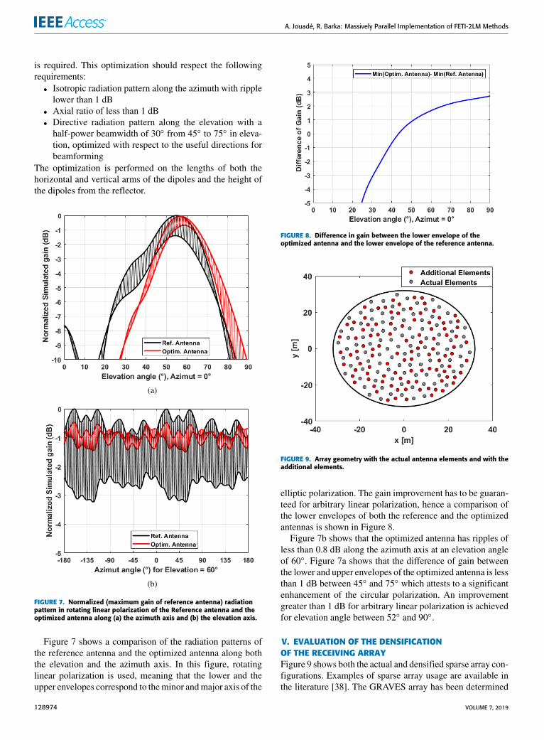
is required. This optimization should respect the followingrequirements:• Isotropic radiation pattern along the azimuth with ripplelower than 1 dB
• Axial ratio of less than 1 dB• Directive radiation pattern along the elevation with ahalf-power beamwidth of 30◦ from 45◦ to 75◦ in eleva-tion, optimized with respect to the useful directions forbeamforming
The optimization is performed on the lengths of both thehorizontal and vertical arms of the dipoles and the height ofthe dipoles from the reflector.
FIGURE 7. Normalized (maximum gain of reference antenna) radiationpattern in rotating linear polarization of the Reference antenna and theoptimized antenna along (a) the azimuth axis and (b) the elevation axis.
Figure 7 shows a comparison of the radiation patterns ofthe reference antenna and the optimized antenna along boththe elevation and the azimuth axis. In this figure, rotatinglinear polarization is used, meaning that the lower and theupper envelopes correspond to theminor andmajor axis of the
FIGURE 8. Difference in gain between the lower envelope of theoptimized antenna and the lower envelope of the reference antenna.
FIGURE 9. Array geometry with the actual antenna elements and with theadditional elements.
elliptic polarization. The gain improvement has to be guaran-teed for arbitrary linear polarization, hence a comparison ofthe lower envelopes of both the reference and the optimizedantennas is shown in Figure 8.
Figure 7b shows that the optimized antenna has ripples ofless than 0.8 dB along the azimuth axis at an elevation angleof 60◦. Figure 7a shows that the difference of gain betweenthe lower and upper envelopes of the optimized antenna is lessthan 1 dB between 45◦ and 75◦ which attests to a significantenhancement of the circular polarization. An improvementgreater than 1 dB for arbitrary linear polarization is achievedfor elevation angle between 52◦ and 90◦.
V. EVALUATION OF THE DENSIFICATIONOF THE RECEIVING ARRAYFigure 9 shows both the actual and densified sparse array con-figurations. Examples of sparse array usage are available inthe literature [38]. The GRAVES array has been determined
128974 VOLUME 7, 2019
A. Jouadé, R. Barka: Massively Parallel Implementation of FETI-2LM Methods
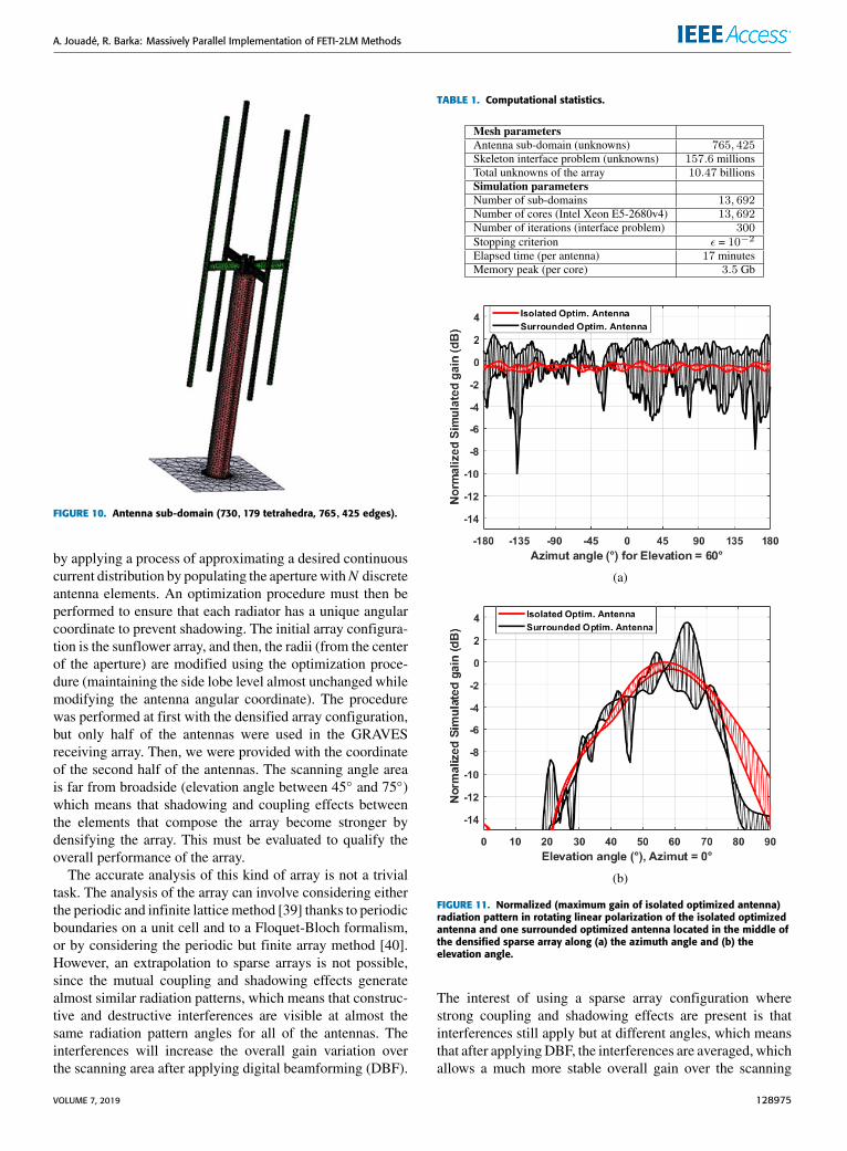
FIGURE 10. Antenna sub-domain (730,179 tetrahedra, 765,425 edges).
by applying a process of approximating a desired continuouscurrent distribution by populating the aperturewithN discreteantenna elements. An optimization procedure must then beperformed to ensure that each radiator has a unique angularcoordinate to prevent shadowing. The initial array configura-tion is the sunflower array, and then, the radii (from the centerof the aperture) are modified using the optimization proce-dure (maintaining the side lobe level almost unchanged whilemodifying the antenna angular coordinate). The procedurewas performed at first with the densified array configuration,but only half of the antennas were used in the GRAVESreceiving array. Then, we were provided with the coordinateof the second half of the antennas. The scanning angle areais far from broadside (elevation angle between 45◦ and 75◦)which means that shadowing and coupling effects betweenthe elements that compose the array become stronger bydensifying the array. This must be evaluated to qualify theoverall performance of the array.
The accurate analysis of this kind of array is not a trivialtask. The analysis of the array can involve considering eitherthe periodic and infinite lattice method [39] thanks to periodicboundaries on a unit cell and to a Floquet-Bloch formalism,or by considering the periodic but finite array method [40].However, an extrapolation to sparse arrays is not possible,since the mutual coupling and shadowing effects generatealmost similar radiation patterns, which means that construc-tive and destructive interferences are visible at almost thesame radiation pattern angles for all of the antennas. Theinterferences will increase the overall gain variation overthe scanning area after applying digital beamforming (DBF).
TABLE 1. Computational statistics.
FIGURE 11. Normalized (maximum gain of isolated optimized antenna)radiation pattern in rotating linear polarization of the isolated optimizedantenna and one surrounded optimized antenna located in the middle ofthe densified sparse array along (a) the azimuth angle and (b) theelevation angle.
The interest of using a sparse array configuration wherestrong coupling and shadowing effects are present is thatinterferences still apply but at different angles, which meansthat after applyingDBF, the interferences are averaged, whichallows a much more stable overall gain over the scanning
VOLUME 7, 2019 128975
A. Jouadé, R. Barka: Massively Parallel Implementation of FETI-2LM Methods
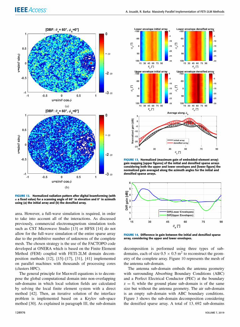
FIGURE 12. Normalized radiation pattern after digital beamforming (withα a fixed value) for a scanning angle of 60◦ in elevation and 0◦ in azimuthusing (a) the initial array and (b) the densified array.
area. However, a full-wave simulation is required, in orderto take into account all of the interactions. As discussedpreviously, commercial electromagnetism simulation toolssuch as CST Microwave Studio [13] or HFSS [14] do notallow for the full-wave simulation of the entire sparse arraydue to the prohibitive number of unknowns of the completemesh. The chosen strategy is the use of the FACTOPO codedeveloped at ONERA which is based on the Finite ElementMethod (FEM) coupled with FETI-2LM domain decom-position methods [12], [15]–[17], [31], [41] implementedon parallel machines with thousands of processing cores(clusters HPC).
The general principle for Maxwell equations is to decom-pose the global computational domain into non-overlappingsub-domains in which local solution fields are calculatedby solving the local finite element system with a directmethod [42]. Then, an iterative solution of the interfaceproblem is implemented based on a Krylov sub-spacemethod [30]. As explained in paragraph III, the sub-domain
FIGURE 13. Normalized (maximum gain of embedded-element array)gain mapping [upper figures] of the initial and densified sparse arraysconsidering both the upper and lower envelopes and [lower figure] thenormalized gain averaged along the azimuth angles for the initial anddensified sparse arrays.
FIGURE 14. Difference in gain between the initial and densified sparsearray, considering the upper and lower envelopes.
decomposition is performed using three types of sub-domains, each of size 0.5 × 0.5 m2 to reconstruct the geom-etry of the complete array. Figure 10 represents the mesh ofthe antenna sub-domain.
The antenna sub-domain embeds the antenna geometrywith surrounding Absorbing Boundary Conditions (ABC)and a Perfect Electrical Conductor (PEC) at the boundaryz = 0, while the ground plane sub-domain is of the samesize but without the antenna geometry. The air sub-domainis an empty sub-domain with ABC boundary conditions.Figure 3 shows the sub-domain decomposition consideringthe densified sparse array. A total of 13, 692 sub-domains
128976 VOLUME 7, 2019
A. Jouadé, R. Barka: Massively Parallel Implementation of FETI-2LM Methods
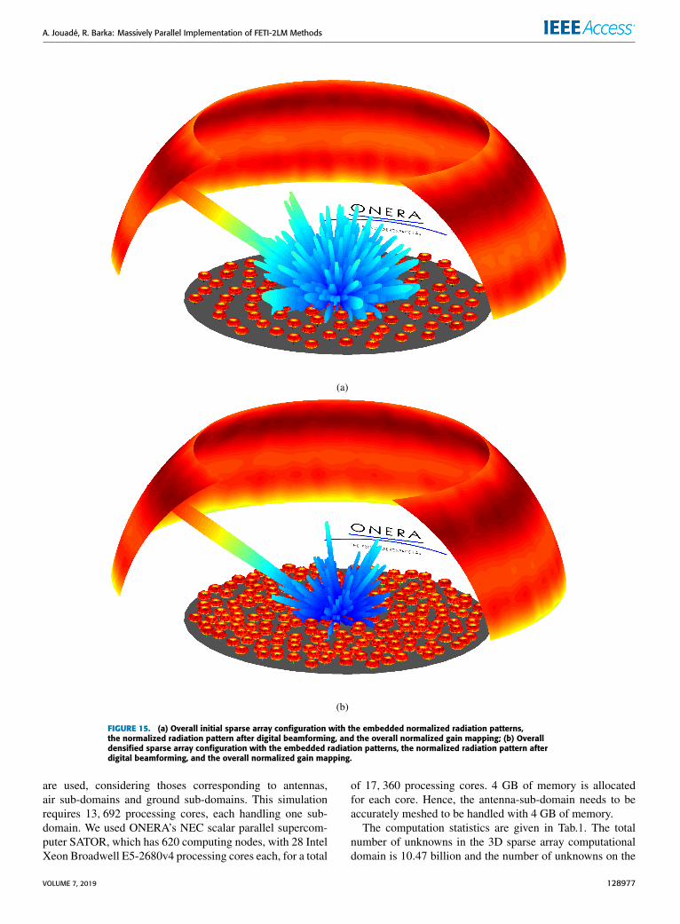
FIGURE 15. (a) Overall initial sparse array configuration with the embedded normalized radiation patterns,the normalized radiation pattern after digital beamforming, and the overall normalized gain mapping; (b) Overalldensified sparse array configuration with the embedded radiation patterns, the normalized radiation pattern afterdigital beamforming, and the overall normalized gain mapping.
are used, considering thoses corresponding to antennas,air sub-domains and ground sub-domains. This simulationrequires 13, 692 processing cores, each handling one sub-domain. We used ONERA’s NEC scalar parallel supercom-puter SATOR, which has 620 computing nodes, with 28 IntelXeon Broadwell E5-2680v4 processing cores each, for a total
of 17, 360 processing cores. 4 GB of memory is allocatedfor each core. Hence, the antenna-sub-domain needs to beaccurately meshed to be handled with 4 GB of memory.
The computation statistics are given in Tab.1. The totalnumber of unknowns in the 3D sparse array computationaldomain is 10.47 billion and the number of unknowns on the
VOLUME 7, 2019 128977
A. Jouadé, R. Barka: Massively Parallel Implementation of FETI-2LM Methods
skeleton interface is 157.6million. The interface problemwassolved through 300 iterations in 17 minutes per antenna witha stopping criteria of 10−2. During this simulation campaignof the initial and densified sparse arrays, a total of 277 hourson 13, 692 processing cores corresponding to 3.8 millionscumulated hours was necessary.
Figure 11 shows a comparison between the radiation pat-tern of the isolated optimized antenna and the radiationpattern of one surrounded optimized antenna located in themiddle of the densified sparse array. This shows that strongcoupling and shadow effects are present, with a gain variationof about 12 dB for the same elevation angle between the lowerand upper envelopes.
By using the surrounded complex radiation patterns of theinitial and densified arrays, DBF is applied for a given scan-ning angle set (elevation angle θs, azimuth angle φs) and themaximum gain of this set is extracted as shown in Figure 12.As an illustration, a stable improvement of 2.5 dB of the Nor-malized Integrated Side Lobe Ratio (NISLR) by densifyingthe sparse array by a factor of 2 is obtained byDDM full-wavesimulation. The NISLR improvement provides the ability todetect weaker targets in the neighborhood of bright targets.The DBF is performed for all sets to provide a gain mappingafter DBF over the full scanning area.
In Figure 13 the gain mapping is shown for both the initialand the densified sparse array configuration, considering thelower and upper envelopes. After averaging the gain mappingalong the azimuth axis, in the bottom plot of Figure 13 thegain variation of each configuration using the rotating linearpolarization is shown.
By comparing the upper and the lower envelopes of theconfigurations, Figure 14 makes it possible to demonstratethat, even with strong shadow and coupling effects due to adensification of the sparse array by a factor of two, we obtainan increase in gain of approximately 3 dB in the required FoVfor an elevation angle between 15◦ and 70◦. Figure 15 showsthe normalized 3D radiation patterns of all of the elements(lower envelope), the digital beamforming in one directionand the gain mapping for the initial and densified sparse arrayconfigurations respectively.
VI. CONCLUSIONA new methodology efficiently handling the simulation oflarge sparse arrays in the VHF band through FETI-2LMdomain decomposition method is proposed in this work.An efficient implementation of a meshing strategy that con-sists in generating the sparse array by populating a regu-lar periodic grid is proposed, and a block Krylov recyclingmethod is implemented to accelerate the simulation of thehundreds of embedded antenna diagrams of the GRAVESsparse array. These novelties implemented in the FETI-2LMallowed the performance of the GRAVES radar sparse receiv-ing array densification be investigated. The results wereobtained using a full-wave simulation, thanks to the capabil-ity of ONERA’s FACTOPO code combined with the use ofthe NEC scalar parallel supercomputer SATOR to simulate
such configuration with an enormous number of unknowns(10.47 billion unknowns). Those intensive simulations, whichrequired 3.8 million cumulated hours and the use of 13, 692Intel Xeon Broadwell E5-2680v4 computing cores, havemade it possible to take into account all of the phenomena,in order to ensure that this densification will not affect theoverall performances and to demonstrate the positive impacton the overall link budget while improving the ability todetect weaker targets in the neighborhood of bright targets.The foreseen evolutions will make GRAVES an even morevaluable key contributor to the SST segment.
ACKNOWLEDGMENTMulti-source FETI simulation algorithms for non periodicapplications have been optimized in part thanks to the GrandEquipement National de Calcul Scientifique through theGrant c2014109083.
REFERENCES[1] T.Michal, J. Eglizeaud, and J. Bouchard, ‘‘Graves: The new French system
for space surveillance,’’ in Proc. 4th Eur. Conf. Space Debris, vol. 587,2005, p. 61.
[2] T. Donath, T. Schildknecht, P. Brousse, J. Laycock, T. Michal, andP. Ameline, ‘‘Proposal for a European space surveillance system,’’ in Proc.4th Eur. Conf. Space Debris, vol. 587, 2005, p. 31.
[3] T. Castaings, B. Pannetier, F. Müller, andM. Rombaut, ‘‘Track initiation inlow-earth-orbit objects using statistical modeling of sparse observations,’’IEEE Trans. Aerosp. Electron. Syst., vol. 51, no. 1, pp. 258–269, Jan. 2015.
[4] T. Castaings, B. Pannetier, F. Müller, and M. Rombaut, ‘‘Sparse dataassociation for low earth orbit tracking,’’ in Proc. IEEE Aerosp. Conf.,Mar. 2012, pp. 1–7.
[5] Air Force Space Surveillance System. Accessed: Aug. 26, 2018. [Online].Available: https://en.wikipedia.org/wiki/AirForceSpaceSurveillanceSystem
[6] Eglin AFB Site C-6. Accessed: Aug. 27, 2019. [Online]. Available:https://en.wikipedia.org/wiki/EglinAFBSiteC-6
[7] Space Fence. Accessed: Jun. 15, 2019. [Online]. Available:https://en.wikipedia.org/wiki/SpaceFence
[8] BallisticMissile EarlyWarning System. Accessed: Dec. 12, 2018. [Online].Available: https://fr.wikipedia.org/wiki/BallisticMissileEarlyWarningSystem
[9] Radar Voronezh. Accessed: May 8, 2019. [Online]. Available:https://fr.wikipedia.org/wiki/BallisticMissileEarlyWarningSystem
[10] J.-M. Jin, The Finite Element Method in Electromagnetics, 2nd ed.New York, NY, USA: Wiley, 2002.
[11] J. L. Volakis, A. Chatterjee, and L. C. Kempel, Finite Element Method forElectromagnetics, Antennas, Circuits Microwaves and Scattering Appli-cations (The IEEE: OUP Series on Electromagnetic Wave Theory), D. G.Dudley, Ed. 1998.
[12] A. Barka, ‘‘Integration of antennas onboard vehicles and diffraction bylarge and complex structures with multiple-domain–multiple-methodstechniques,’’ Proc. IEEE, vol. 101, no. 2, pp. 280–297, Feb. 2013.
[13] CST Microwave Studio. Accessed: Sep. 2019. [Online]. Available:https://www.3ds.com/products-services/simulia/products/cst-studio-suite/
[14] ANSYS HFSS. Accessed: Sep. 2019. [Online]. Available:https://www.ansys.com/products/electronics/ansys-hfss
[15] A. Barka, P. Soudais, and D. Volpert, ‘‘Scattering from 3-D cavitieswith a plug and play numerical scheme combining IE, PDE, and modaltechniques,’’ IEEE Trans. Antennas Propag., vol. 48, no. 5, pp. 704–712,May 2000.
[16] A. Barka and P. Caudrillier, ‘‘Domain decomposition method based ongeneralized scattering matrix for installed performance of antennas onaircraft,’’ IEEE Trans. Antennas Propag., vol. 55, no. 6, pp. 1833–1842,Jun. 2007.
[17] A. Barka and C. Picard, ‘‘Implementation of spectral basis functionsin BEM/FEM/GSM domain decomposition methods devoted to scat-tering and radiation applications,’’ Comput. Phys. Commun., vol. 178,pp. 438–448, Mar. 2008.
128978 VOLUME 7, 2019

A. Jouadé, R. Barka: Massively Parallel Implementation of FETI-2LM Methods
[18] R. Chiniard, A. Barka, and O. Pascal, ‘‘Hybrid FEM/floquet modes/POtechnique for multi-incidence RCS prediction of array antennas,’’ IEEETrans. Antennas Propag., vol. 56, no. 6, pp. 1679–1686, Jun. 2008.
[19] A. Barka and N. Douchin, ‘‘Asymptotic simplifications for hybridBEM/GO/PO/PTD techniques based on a generalized scattering matrixapproach,’’ Comput. Phys. Commun., vol. 183, pp. 1928–1936, Sep. 2012.
[20] P. Bjørstad and O. B. Widlund, ‘‘Iterative methods for the solution of ellip-tic problems on regions partitioned into substructures,’’ SIAM J. Numer.Anal., vol. 23, no. 6, pp. 1097–1120, 1986.
[21] C. Farhat and F.-X. Roux, ‘‘A method of finite element tearing and inter-connecting and its parallel solution algorithm,’’ Int. J. Numer. MethodsEng., vol. 32, no. 6, pp. 1205–1227, Oct. 1991.
[22] A. de La Bourdonnaye, C. Farhat, A. Macedo, F. Magoulès, and F. Roux,‘‘A non-overlapping domain decomposition method for the exteriorHelmoltz problem,’’ Contemp. Math., vol. 218, pp. 42–66, Jan. 1998.
[23] G. Cohen, L. Halpern, and P. Joly, Mathematical and Numerical Aspectsof Wave Propagation Phenomena. Philadelphia, PA, USA: SIAM, 1991,pp. 44–52.
[24] C. Farhat, L. Crivelli, and F. X. Roux, ‘‘Extending substructure basediterative solvers to multiple load and repeated analyses,’’ Compt. MethodsAppl. Mech. Eng., vol. 117, pp. 195–209, Jul. 1994.
[25] R. Tezaur, A. Macedo, and C. Farhat, ‘‘Iterative solution of large-scaleacoustic scattering problems with multiple right hand-sides by a domaindecomposition method with Lagrange multipliers,’’ Int. J. Numer. MethodsEng., vol. 51, pp. 1175–1193, Aug. 2001.
[26] M. N. Vouvakis, Z. Cendes, and J.-F. Lee, ‘‘A FEM domain decompositionmethod for photonic and electromagnetic band gap structures,’’ IEEETrans. Antennas Propag., vol. 54, no. 2, pp. 721–733, Feb. 2006.
[27] K. Zhao, V. Rawat, S.-C. Lee, and J.-F. Lee, ‘‘A domain decompositionmethod with nonconformal meshes for finite periodic and semi-periodicstructures,’’ IEEE Trans. Antennas Propag., vol. 55, no. 9, pp. 2559–2570,Sep. 2007.
[28] M. L. Parks, E. de Sturler, G. Mackey, D. D. Johnson, and S. Maiti,‘‘Recycling Krylov subspaces for sequences of linear systems,’’ SIAMJ. Sci. Comput., vol. 28, no. 5, pp. 1651–1674, Oct. 2006.
[29] Z. Peng, M. B. Stephanson, and J.-F. Lee, ‘‘Fast computation of angularresponses of large-scale three-dimensional electromagnetic wave scat-tering,’’ IEEE Trans. Antennas Propag., vol. 58, no. 9, pp. 3004–3012,Sep. 2010.
[30] F.-X. Roux and A. Barka, ‘‘Block Krylov recycling algorithms for FETI-2LM applied to 3-D electromagnetic wave scattering and radiation,’’ IEEETrans. Antennas Propag., vol. 65, no. 4, pp. 1886–1895, Apr. 2017.
[31] A. Barka, S.Matos, J. R. Costa, and C. A. Fernandes, ‘‘Assessment of FETIDDM methodologies for the simulation of high gain Ka-band transmitarrays,’’ in Proc. Int. Symp. Antennas Propag. (ISAP), Oct./Nov. 2017,pp. 1–2.
[32] METIS—Serial Graph Partitioning and Fill-Reducing MatrixOrdering. Accessed: Sep. 2019. [Online]. Available: http://glaros.dtc.umn.edu/gkhome/views/metis
[33] M. F. Xue and J. M. Jin, ‘‘A hybrid conformal/nonconformal domaindecomposition method for multi-region electromagnetic modeling,’’ IEEETrans. Antennas Propag., vol. 62, no. 4, pp. 2009–2021, Apr. 2014.
[34] Gid the Personal Pre and Post Processor. [Online]. Available:https://www.gidhome.com
[35] F.-X. Roux and A. Barka, ‘‘FETI methods,’’ in Computational Electro-magnetics: Recent Advances and Engineering Applications, R. Mittra, Ed.New York, NY, USA: Springer, 2014.
[36] J. C. Nedelec, ‘‘Mixed finite elements inR3,’’ Numer. Math., vol. 35, no. 3,pp. 315–341, Sep. 1980.
[37] Y. Saad, Iterative Methods for Sparse Linear Systems. Philadelphia,PA, USA: SIAM, 2003. [Online]. Available: https://www-users.cs.umn.edu/~saad/books.html
[38] A. Ramalli and P. Tortoli, ‘‘256-element density-tapered spiral matrices forultrasound phased imaging,’’ in Proc. Ultrason. Symp. (IUS), Sep. 2014,pp. 2087–2090.
[39] R. J. Mailloux, Phased Array Antenna Handbook. Norwood,MA, USA: Artech House, 2017.
[40] B. Lesur, A. Maati, M. Thevenot, C. Menudier, E. Arnaud, T. Monediere,C.Melle, D. Chaimbault, andA. Karas, ‘‘A large antenna array for Ka-bandsatcom-on-the-move applications—Accurate modeling and experimen-tal characterization,’’ IEEE Trans. Antennas Propag., vol. 66, no. 9,pp. 4586–4595, Sep. 2018.
[41] F.-X. Roux and A. Barka, ‘‘Block krylov recycling algorithms forFETI-2LM applied to 3-D electromagnetic wave scattering and radia-tion,’’ IEEE Trans. Antennas Propag., vol. 65, no. 4, pp. 1886–1895,Apr. 2017.
[42] Intel MKL PARDISO, Developer Reference for Intel Math KernelLibrary—Fortran. Accessed: May 23, 2019. [Online]. Available:https://software.intel.com/en-us/mkl-developer-reference-fortran-intel-mkl-pardiso-parallel-direct-sparse-solver-interface
ANTOINE JOUADÉ received the M.Sc. degreein signal processing and telecommunication engi-neering from the University of Rennes 1, Rennes,France, and the Ph.D. degree in signal process-ing and telecommunications from the Institute ofElectronics and Telecommunications, Universityof Rennes 1, in 2017. He was an Intern with theAntenna and Sub-Millimeter Section, EuropeanSpace and Technology Center, European SpaceAgency, ESA ESTEC, Noordwijk, The Nether-
lands. He is currently a Research Engineer with the French Aerospace Lab-oratory (ONERA), Electromagnetism and Radar Department. His researchinterests include radar, signal processing, and associated antennas.
ANDRÉ BARKA received the M.Sc. and Ph.D.degrees in applied mathematics from the Uni-versity of Bordeaux, France, in 1986 and 1990,respectively, and the Habilitation à Diriger desRecherches (HDR) degree from the University ofToulouse, in 2008. He is currently a Ph.D. Advisorwith the GEET Doctoral School, Toulouse. Hejoined ONERA, in 1989, where he is in chargeof developing advanced multidomain and multi-method techniques combining integral equations,
finite element methods, and asymptotic techniques. He was the Work-Package Manager of advanced modeling activities in the FP6 IPAS Euro-pean Project and the H2020 EPICEA European/Canadian Project. FromSeptember 2016 to September 2017, he was an Invited Researcher withthe Telecommunications Institute, University of Lisbon, Portugal, througha research convention with ONERA, the French DoD, and the University ofLisbon. He is also a Senior Scientist with more than 20 years of researchexperience in computational electromagnetics (and especially in domaindecomposition methods), in various application fields, such as electromag-netic compatibility, radar cross section, and antennas. His current researchinterests include the design and realization of new antenna concepts basedon metamaterials, and advanced domain decomposition methods, includingfinite element tearing and interconnecting (FETI) and integral equationdomain decomposition methods (IE-DDM). He has been a member of theBoard of Computer Physics Communications journal, since 2006, and aComputational Electromagnetic Specialist Editor.
VOLUME 7, 2019 128979