Embed Size (px)
Citation preview
Page 1 of 2
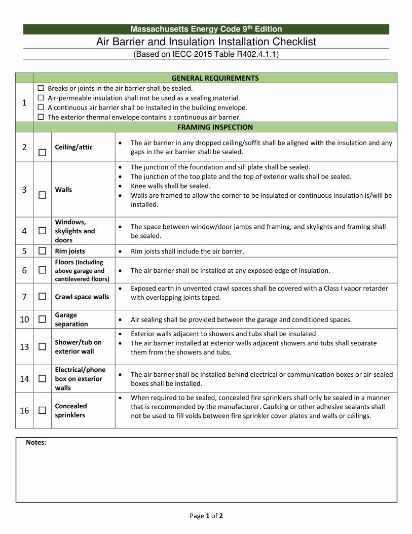
Massachusetts Energy Code 9th Edition
Air Barrier and Insulation Installation Checklist (Based on IECC 2015 Table R402.4.1.1)
GENERAL REQUIREMENTS
1
☐ Breaks or joints in the air barrier shall be sealed.
☐ Air-permeable insulation shall not be used as a sealing material.
☐ A continuous air barrier shall be installed in the building envelope.
☐ The exterior thermal envelope contains a continuous air barrier. FRAMING INSPECTION
2
☐ Ceiling/attic
• The air barrier in any dropped ceiling/soffit shall be aligned with the insulation and any
gaps in the air barrier shall be sealed.
3
☐ Walls
• The junction of the foundation and sill plate shall be sealed.
• The junction of the top plate and the top of exterior walls shall be sealed.
• Knee walls shall be sealed.
• Walls are framed to allow the corner to be insulated or continuous insulation is/will be
installed.
4 ☐ Windows,
skylights and
doors
• The space between window/door jambs and framing, and skylights and framing shall
be sealed.
5 ☐ Rim joists • Rim joists shall include the air barrier.
6 ☐ Floors (including
above garage and
cantilevered floors) • The air barrier shall be installed at any exposed edge of insulation.
7 ☐ Crawl space walls • Exposed earth in unvented crawl spaces shall be covered with a Class I vapor retarder
with overlapping joints taped.
10 ☐ Garage
separation • Air sealing shall be provided between the garage and conditioned spaces.
13 ☐ Shower/tub on
exterior wall
• Exterior walls adjacent to showers and tubs shall be insulated
• The air barrier installed at exterior walls adjacent showers and tubs shall separate
them from the showers and tubs.
14 ☐ Electrical/phone
box on exterior
walls
• The air barrier shall be installed behind electrical or communication boxes or air-sealed
boxes shall be installed.
16 ☐ Concealed
sprinklers
• When required to be sealed, concealed fire sprinklers shall only be sealed in a manner
that is recommended by the manufacturer. Caulking or other adhesive sealants shall
not be used to fill voids between fire sprinkler cover plates and walls or ceilings.
Notes:
Page 2 of 2
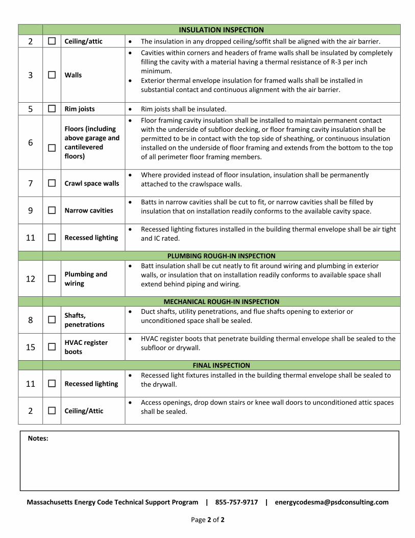
INSULATION INSPECTION
2 ☐ Ceiling/attic • The insulation in any dropped ceiling/soffit shall be aligned with the air barrier.
3 ☐ Walls
• Cavities within corners and headers of frame walls shall be insulated by completely
filling the cavity with a material having a thermal resistance of R-3 per inch
minimum.
• Exterior thermal envelope insulation for framed walls shall be installed in
substantial contact and continuous alignment with the air barrier.
5 ☐ Rim joists • Rim joists shall be insulated.
6
☐
Floors (including
above garage and
cantilevered
floors)
• Floor framing cavity insulation shall be installed to maintain permanent contact
with the underside of subfloor decking, or floor framing cavity insulation shall be
permitted to be in contact with the top side of sheathing, or continuous insulation
installed on the underside of floor framing and extends from the bottom to the top
of all perimeter floor framing members.
7 ☐ Crawl space walls
• Where provided instead of floor insulation, insulation shall be permanently
attached to the crawlspace walls.
9 ☐ Narrow cavities • Batts in narrow cavities shall be cut to fit, or narrow cavities shall be filled by
insulation that on installation readily conforms to the available cavity space.
11 ☐ Recessed lighting • Recessed lighting fixtures installed in the building thermal envelope shall be air tight
and IC rated.
PLUMBING ROUGH-IN INSPECTION
12 ☐ Plumbing and
wiring
• Batt insulation shall be cut neatly to fit around wiring and plumbing in exterior
walls, or insulation that on installation readily conforms to available space shall
extend behind piping and wiring.
MECHANICAL ROUGH-IN INSPECTION
8 ☐ Shafts,
penetrations
• Duct shafts, utility penetrations, and flue shafts opening to exterior or
unconditioned space shall be sealed.
15 ☐ HVAC register
boots
• HVAC register boots that penetrate building thermal envelope shall be sealed to the
subfloor or drywall.
FINAL INSPECTION
11 ☐ Recessed lighting
• Recessed light fixtures installed in the building thermal envelope shall be sealed to
the drywall.
2 ☐ Ceiling/Attic
• Access openings, drop down stairs or knee wall doors to unconditioned attic spaces
shall be sealed.
Notes:
Massachusetts Energy Code Technical Support Program | 855-757-9717 | [email protected]
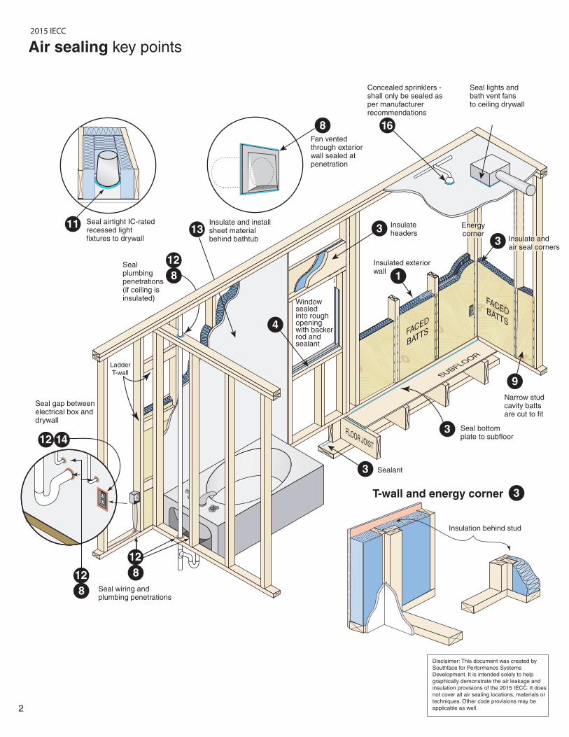
Ladder
T-wall
Insulate and install sheet material behind bathtub
FLOOR JOIST
Sealant
Seal wiring and plumbing penetrations
2
Insulated exterior wall
Seal airtight IC-rated recessed light fixtures to drywall
Air sealing key points
4
Seal lights andbath vent fansto ceiling drywall
Concealed sprinklers - shall only be sealed as per manufacturerrecommendations
16
Insulateheaders3
1
3
Seal bottom plate to subfloor
3
3
3
11 13
12
12
8
12
8
8
14
8Fan vented through exterior wall sealed at penetration
SUBFLOOR
Insulate and air seal corners
9
Narrow stud cavity batts are cut to fit
Seal plumbingpenetrations (if ceiling is insulated)
Seal gap between electrical box and drywall
Disclaimer: This document was created by
Southface for Performance Systems
Development. It is intended solely to help
graphically demonstrate the air leakage and
insulation provisions of the 2015 IECC. It does
not cover all air sealing locations, materials or
techniques. Other code provisions may be
applicable as well.
12
FACED
BATTS
FACEDBATTS
Energycorner
Window sealedinto roughopening with backer rod and sealant
Insulation behind stud
T-wall and energy corner
2015 IECC
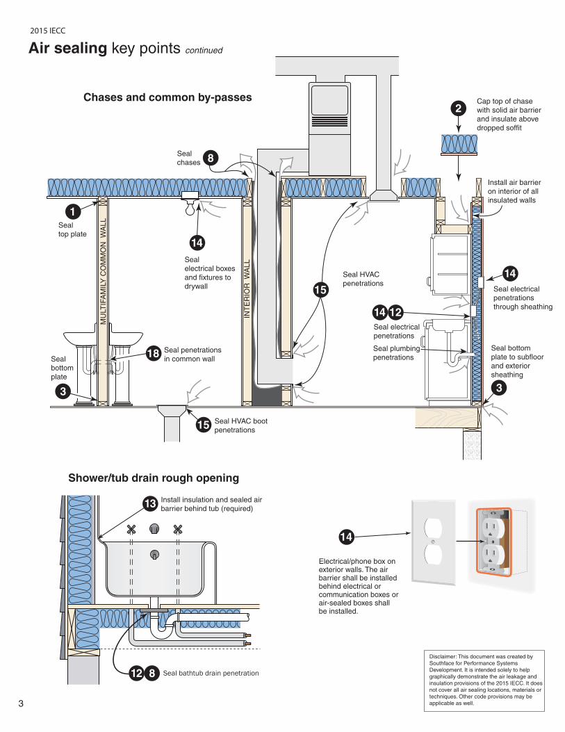
Electrical/phone box on exterior walls. The air barrier shall be installed behind electrical or communication boxes or air-sealed boxes shall be installed.
14
3
Chases and common by-passes
Seal
chases
Seal HVAC
penetrations
Seal HVAC boot
penetrations
Seal electrical
penetrations
Seal plumbing
penetrations
Seal
electrical boxes
and fixtures to
drywall 15
8
14
3
2
15
3
1214
Seal electrical
penetrations
through sheathing
14
Seal bathtub drain penetration
13
12 8
Install insulation and sealed air
barrier behind tub (required)
Shower/tub drain rough opening
Cap top of chase
with solid air barrier
and insulate above
dropped soffit
Install air barrier
on interior of all
insulated walls
Seal bottom
plate to subfloor
and exterior
sheathing
MU
LTIF
AM
ILY
CO
MM
ON
W
ALL
INT
ER
IOR
W
ALL
Seal penetrations
in common wall
Seal
top plate
Seal
bottom
plate
1
18
Disclaimer: This document was created by
Southface for Performance Systems
Development. It is intended solely to help
graphically demonstrate the air leakage and
insulation provisions of the 2015 IECC. It does
not cover all air sealing locations, materials or
techniques. Other code provisions may be
applicable as well.
Air sealing key points continued
2015 IECC
4
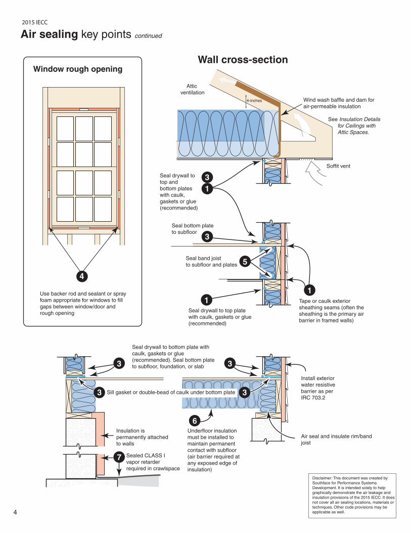
Soffit vent
Attic
ventilation
Seal band joist
to subfloor and plates
Seal bottom plate
to subfloor
Wall cross-section
1
5
3
7
6
1
3
3
Seal drywall to bottom plate with
caulk, gaskets or glue
(recommended). Seal bottom plate
to subfloor, foundation, or slab
Seal drywall to top plate
with caulk, gaskets or glue
(recommended)
4
Window rough opening
Use backer rod and sealant or spray
foam appropriate for windows to fill
gaps between window/door and
rough opening
Air sealing key points continued
Wind wash baffle and dam for
air-permeable insulation
See Insulation Details
for Ceilings with
Attic Spaces.
Install exterior
water resistive
barrier as per
IRC 703.2
Air seal and insulate rim/band
joist
Tape or caulk exterior
sheathing seams (often the
sheathing is the primary air
barrier in framed walls)
1
Sill gasket or double-bead of caulk under bottom plate
3
Sealed CLASS I
vapor retarder
required in crawlspace
Insulation is
permanently attached
to walls
Underfloor insulation
must be installed to
maintain permanent
contact with subfloor
(air barrier required at
any exposed edge of
insulation)
4-inches
3
Disclaimer: This document was created by
Southface for Performance Systems
Development. It is intended solely to help
graphically demonstrate the air leakage and
insulation provisions of the 2015 IECC. It does
not cover all air sealing locations, materials or
techniques. Other code provisions may be
applicable as well.
Seal drywall to
top and
bottom plates
with caulk,
gaskets or glue
(recommended)
3
2015 IECC
5
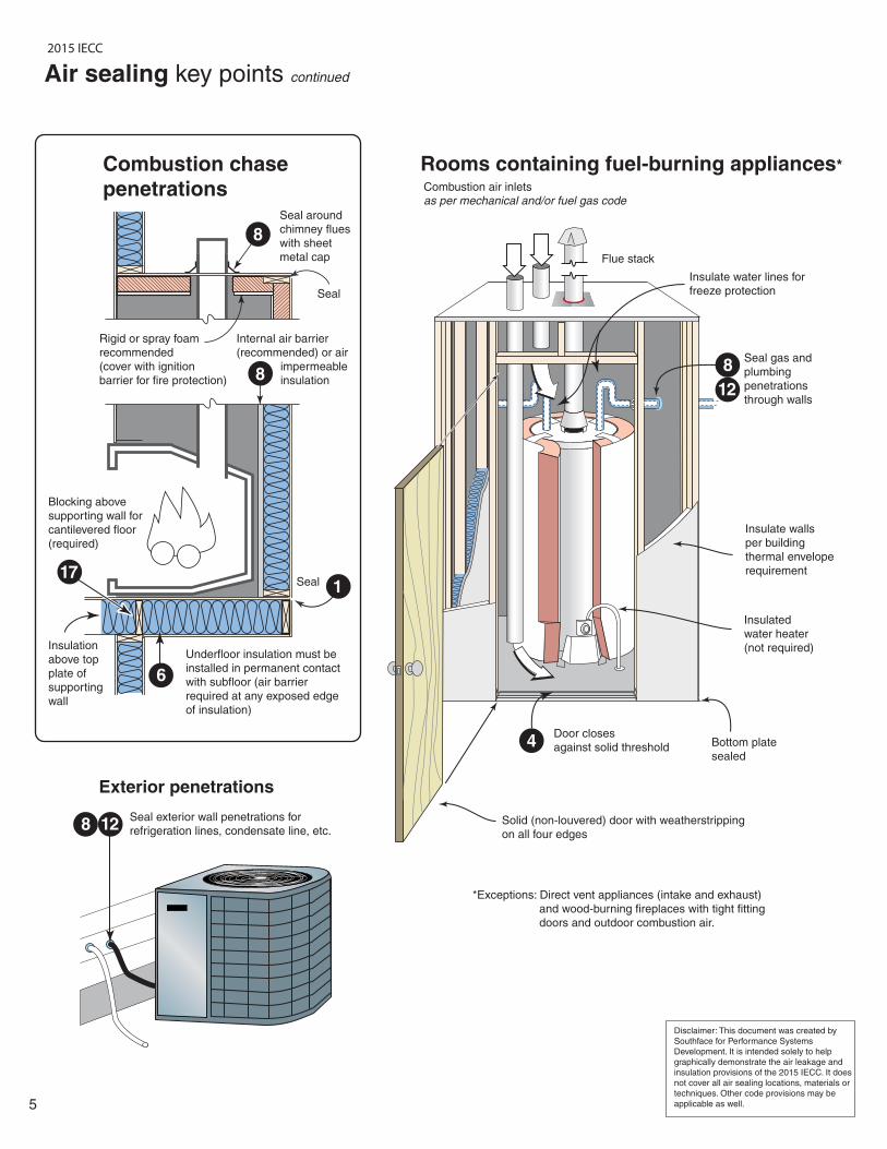
Seal around
chimney flues
with sheet
metal cap
Rooms containing fuel-burning appliances*
Exterior penetrations
Combustion chase
penetrations
Solid (non-louvered) door with weatherstripping
on all four edges
Door closes
against solid threshold Bottom plate
sealed
Seal gas and
plumbing
penetrations
through walls
Combustion air inletsas per mechanical and/or fuel gas code
Flue stack
8
8
4
12
12
8
6
Seal exterior wall penetrations for
refrigeration lines, condensate line, etc.
Air sealing key points continued
Seal
Internal air barrier
(recommended) or air
impermeable
insulation
Rigid or spray foam
recommended
(cover with ignition
barrier for fire protection)
Seal
Insulate walls
per building
thermal envelope
requirement
Insulated
water heater
(not required)
Blocking above
supporting wall for
cantilevered floor
(required)
Underfloor insulation must be
installed in permanent contact
with subfloor (air barrier
required at any exposed edge
of insulation)
Insulation
above top
plate of
supporting
wall
8
171
Disclaimer: This document was created by
Southface for Performance Systems
Development. It is intended solely to help
graphically demonstrate the air leakage and
insulation provisions of the 2015 IECC. It does
not cover all air sealing locations, materials or
techniques. Other code provisions may be
applicable as well.
Insulate water lines for
freeze protection
*Exceptions: Direct vent appliances (intake and exhaust)
and wood-burning fireplaces with tight fitting
doors and outdoor combustion air.
2015 IECC
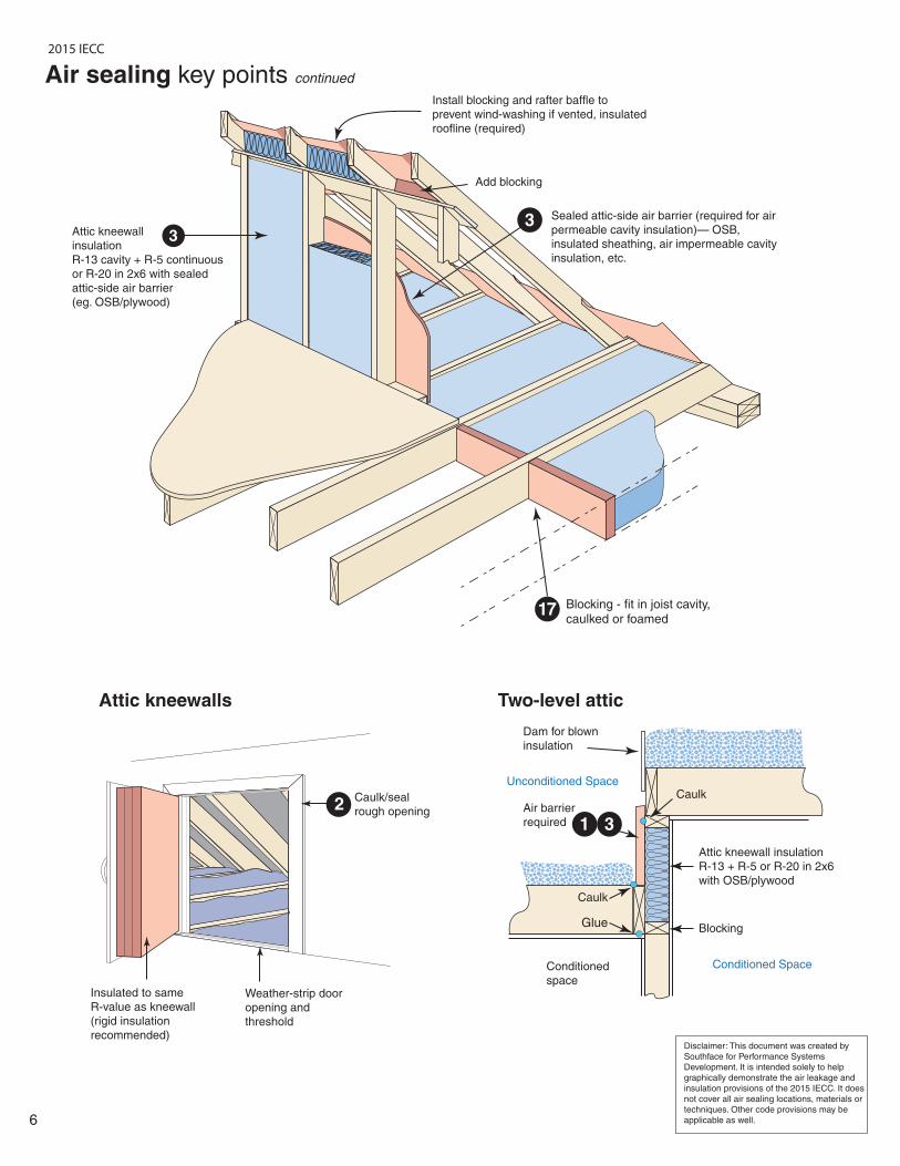
Blocking - fit in joist cavity, caulked or foamed
17
33 Sealed attic-side air barrier (required for air
permeable cavity insulation)— OSB,
insulated sheathing, air impermeable cavity
insulation, etc.
Install blocking and rafter baffle to
prevent wind-washing if vented, insulated
roofline (required)
Add blocking
6
Attic kneewalls
2Caulk/seal
rough opening
Weather-strip door
opening and
threshold
Air sealing key points continued
Insulated to same
R-value as kneewall
(rigid insulation
recommended)
Two-level attic
Conditioned Space
Unconditioned Space
Conditioned
space
Caulk
Caulk
BlockingGlue
Air barrier
required
Dam for blown
insulation
1 3
Attic kneewall
insulation
R-13 cavity + R-5 continuous
or R-20 in 2x6 with sealed
attic-side air barrier
(eg. OSB/plywood)
Attic kneewall insulation
R-13 + R-5 or R-20 in 2x6
with OSB/plywood
Disclaimer: This document was created by
Southface for Performance Systems
Development. It is intended solely to help
graphically demonstrate the air leakage and
insulation provisions of the 2015 IECC. It does
not cover all air sealing locations, materials or
techniques. Other code provisions may be
applicable as well.
2015 IECC
7
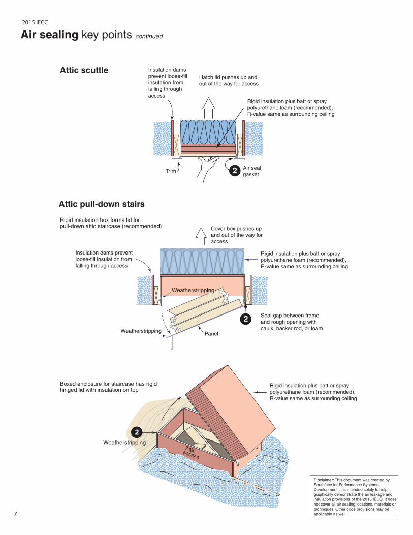
PanelWeatherstripping
Cover box pushes up
and out of the way for
access
Seal gap between frame
and rough opening with
caulk, backer rod, or foam
Rigid insulation box forms lid for pull-down attic staircase (recommended)
Boxed enclosure for staircase has rigid hinged lid with insulation on top
Insulation dams prevent
loose-fill insulation from
falling through access
Hatch lid pushes up and
out of the way for access
Rigid insulation plus batt or spray
polyurethane foam (recommended),
R-value same as surrounding ceiling
Air seal
gasketTrim
Insulation dams
prevent loose-fill
insulation from
falling through
access
Attic pull-down stairs
Attic scuttle
2
2
Air sealing key points continued
Attic access
Weatherstripping
2
Weatherstripping
Disclaimer: This document was created by
Southface for Performance Systems
Development. It is intended solely to help
graphically demonstrate the air leakage and
insulation provisions of the 2015 IECC. It does
not cover all air sealing locations, materials or
techniques. Other code provisions may be
applicable as well.
Rigid insulation plus batt or spray
polyurethane foam (recommended),
R-value same as surrounding ceiling
Rigid insulation plus batt or spray
polyurethane foam (recommended),
R-value same as surrounding ceiling
2015 IECC

8
Disclaimer: This document was created by
Southface for Performance Systems
Development. It is intended solely to help
graphically demonstrate the air leakage and
insulation provisions of the 2015 IECC. It does
not cover all air sealing locations, materials or
techniques. Other code provisions may be
applicable as well.
Garage blocking and sealing key pointsBlocking, air sealing and insulation required above garage separation wall
Garage separation
wall cavity insulation
Insulation
Blocking
Air seal at
edges of
blocking
HOUSE SIDE
GARAGE
SIDE
2015 IECC
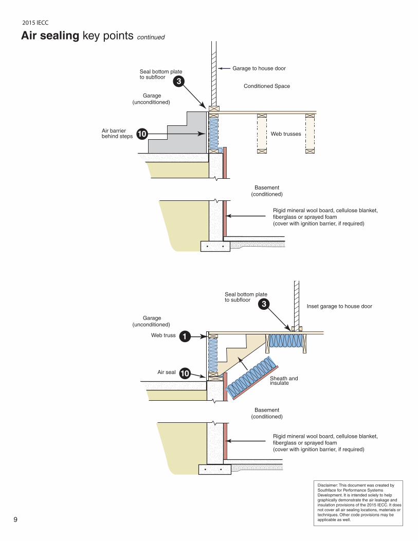
Conditioned Space
9
Air sealing key points continued
Seal bottom plate to subfloor
Air barrierbehind steps Web trusses
Basement
(conditioned)
Garage
(unconditioned)
Garage to house door
Sheath and insulate
Basement
(conditioned)
Garage
(unconditioned)
Inset garage to house door
Air seal
Rigid mineral wool board, cellulose blanket,
fiberglass or sprayed foam
(cover with ignition barrier, if required)
Rigid mineral wool board, cellulose blanket,
fiberglass or sprayed foam
(cover with ignition barrier, if required)
10
10
3
Web truss 1
Disclaimer: This document was created by
Southface for Performance Systems
Development. It is intended solely to help
graphically demonstrate the air leakage and
insulation provisions of the 2015 IECC. It does
not cover all air sealing locations, materials or
techniques. Other code provisions may be
applicable as well.
Seal bottom plate to subfloor
3
2015 IECC

10
Disclaimer: This document was created by
Southface for Performance Systems
Development. It is intended solely to help
graphically demonstrate the air leakage and
insulation provisions of the 2015 IECC. It does
not cover all air sealing locations, materials or
techniques. Other code provisions may be
applicable as well.
Seal seams then
install duct wrap
Ceiling
register
Caulk between
drywall and boot
Seal flange
with mastic
Seal elbow gores
with mastic
Mastic
Mastic
Mastic at
swivel joints
(gores)
Mastic
Supply
leakage
Supply leakage
Supply
air
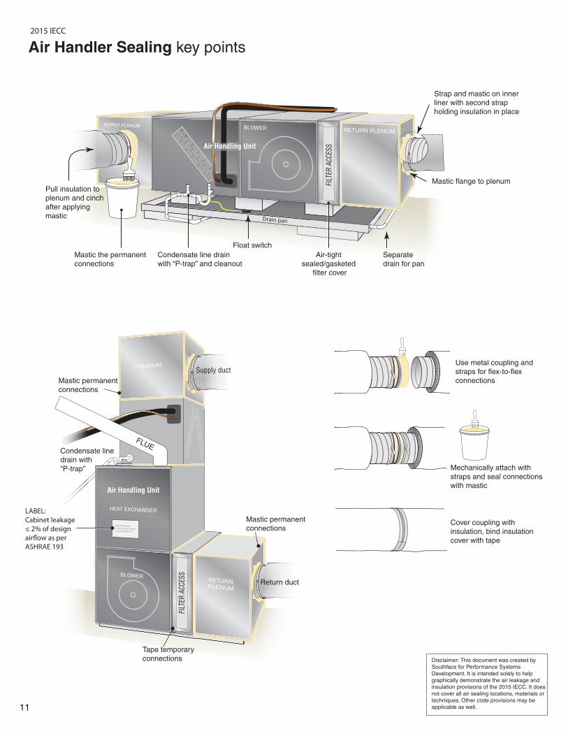
Duct Sealing key points
Seal joints and edges
of sheet metal box
with mastic
Seal box to subfloor
All closure systems shall have
mastic applied that is at least
0.08 inches (2mm) thick.
All seams in plenums, trunk lines and
boots must be sealed with mastic or
mastic tape.
Seal gaps
between boot
and drywallSeal boot
seams and
then insulate
2015 IECC
11
Disclaimer: This document was created by
Southface for Performance Systems
Development. It is intended solely to help
graphically demonstrate the air leakage and
insulation provisions of the 2015 IECC. It does
not cover all air sealing locations, materials or
techniques. Other code provisions may be
applicable as well.
FILT
ER A
CC
ESS
Mastic the permanent
connections
Condensate line drain
with “P-trap” and cleanout
Float switch
Separate
drain for pan
Air-tight
sealed/gasketed
filter cover
Pull insulation to
plenum and cinch
after applying
mastic
Return duct
Mastic permanent
connections
Tape temporary
connections
Supply duct
Air Handling Unit
Mastic permanent
connections
Condensate line
drain with
“P-trap”
Strap and mastic on inner
liner with second strap
holding insulation in place
Mastic flange to plenum
Air Handler Sealing key points
Air Handling Unit
FILT
ER A
CC
ESS
FLUE
Use metal coupling and
straps for flex-to-flex
connections
Mechanically attach with
straps and seal connections
with mastic
Cover coupling with
insulation, bind insulation
cover with tape
LABEL:
Cabinet leakage
≤ 2% of design
air�ow as per
ASHRAE 193
2015 IECC
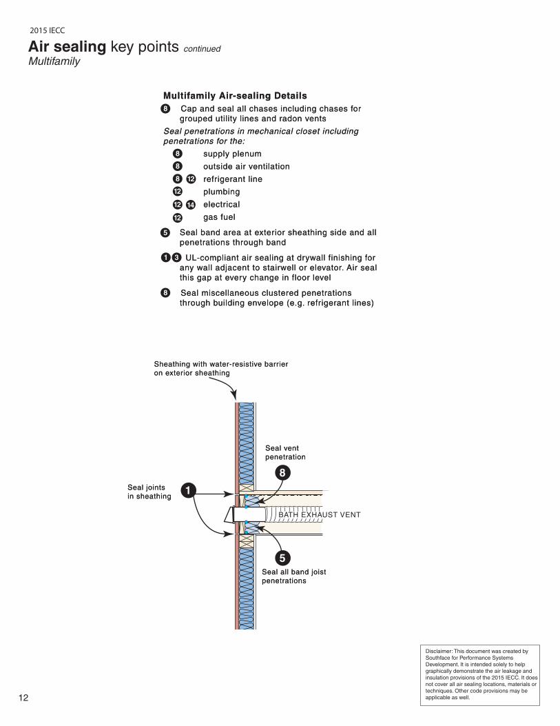
Multifamily Air-sealing Details
8 Cap and seal all chases including chases for
grouped utility lines and radon vents
Seal penetrations in mechanical closet including
penetrations for the:
supply plenum
outside air ventilation
refrigerant line
plumbing
electrical
gas fuel
Seal band area at exterior sheathing side and all
penetrations through band
UL-compliant air sealing at drywall finishing for
any wall adjacent to stairwell or elevator. Air seal
this gap at every change in floor level
Seal miscellaneous clustered penetrations
through building envelope (e.g. refrigerant lines)
Seal all band joist
penetrations
Seal all band joist
penetrations
Seal vent
penetration
Seal vent
penetration
Seal joints
in sheathing
Seal joints
in sheathing
Sheathing with water-resistive barrier
on exterior sheathing
Sheathing with water-resistive barrier
on exterior sheathing
BATH EXHAUST VENT
12
Air sealing key points continued
Multifamily
Disclaimer: This document was created by
Southface for Performance Systems
Development. It is intended solely to help
graphically demonstrate the air leakage and
insulation provisions of the 2015 IECC. It does
not cover all air sealing locations, materials or
techniques. Other code provisions may be
applicable as well.
1
8
5
12
12
12
12
14
5
1 3
8
8
8
8
8
2015 IECC
CONCRETE
MASONRY UNIT
STAIRWELL
or ELEVATOR
CHASE
CONCRETE
MASONRY UNIT
STAIRWELL
or ELEVATOR
CHASE
FRAMED
MULTI-STORY
LIVING UNITS
FRAMED
MULTI-STORY
LIVING UNITS
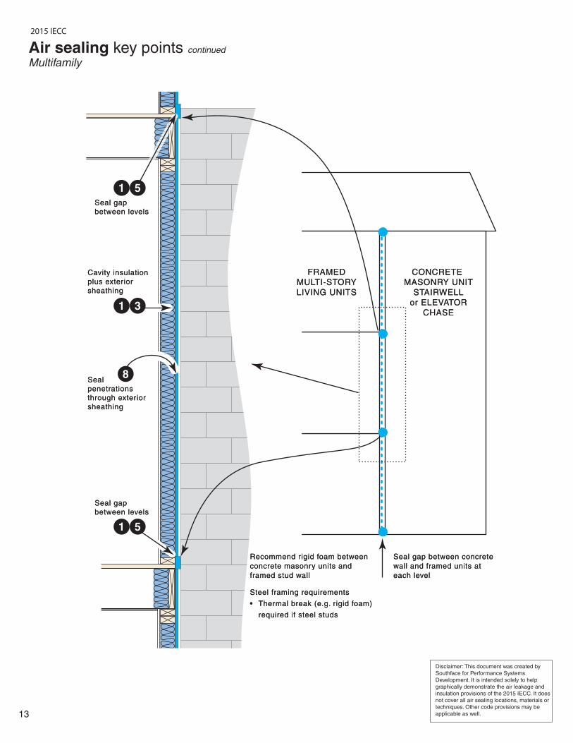
Seal gap between concrete
wall and framed units at
each level
Seal gap between concrete
wall and framed units at
each level
Recommend rigid foam between
concrete masonry units and
framed stud wall
Steel framing requirements
• Thermal break (e.g. rigid foam)
required if steel studs
Recommend rigid foam between
concrete masonry units and
framed stud wall
Steel framing requirements
• Thermal break (e.g. rigid foam)
required if steel studs
Seal gap
between levels
Seal gap
between levels
Seal gap
between levels
Seal gap
between levels
Cavity insulation
plus exterior
sheathing
Cavity insulation
plus exterior
sheathing
Seal
penetrations
through exterior
sheathing
Seal
penetrations
through exterior
sheathing
13
Air sealing key points continued Multifamily
Disclaimer: This document was created by
Southface for Performance Systems
Development. It is intended solely to help
graphically demonstrate the air leakage and
insulation provisions of the 2015 IECC. It does
not cover all air sealing locations, materials or
techniques. Other code provisions may be
applicable as well.
51
1
31
8
5
2015 IECC

LOUVERED DOORLOUVERED DOOR
AIR
HANDLER
AIR
HANDLER
PLENUMPLENUM
WATER HEATERWATER HEATER
UTILITY
CHASE
UTILITY
CHASE
Utility chase
capped and
sealed at
perimeter -
at all levels
Utility chase
capped and
sealed at
perimeter -
at all levels
Seal perimeter of
drain penetration
Seal perimeter of
drain penetration
Seal plumbing
penetration
Seal plumbing
penetration
Seal electrical
and plumbing
penetrations
Seal electrical
and plumbing
penetrations
Utility chase
capped and
sealed at
perimeter -
at all levels
Utility chase
capped and
sealed at
perimeter -
at all levels
Seal electrical and
plumbing penetrations
Seal electrical and
plumbing penetrations
Seal refrigerant
penetration
Seal refrigerant
penetration
Seal plenum
penetration
through drywall
Seal plenum
penetration
through drywall
14
Air sealing key points continued
Multifamily Mechanical Closet
8
8
8
8
128
12
128
128
Disclaimer: This document was created by
Southface for Performance Systems
Development. It is intended solely to help
graphically demonstrate the air leakage and
insulation provisions of the 2015 IECC. It does
not cover all air sealing locations, materials or
techniques. Other code provisions may be
applicable as well.
COILSCOILS
TILTED
FILTER
TILTED
FILTER
8
2015 IECC
Basement(conditioned or
indirectly-conditioned)
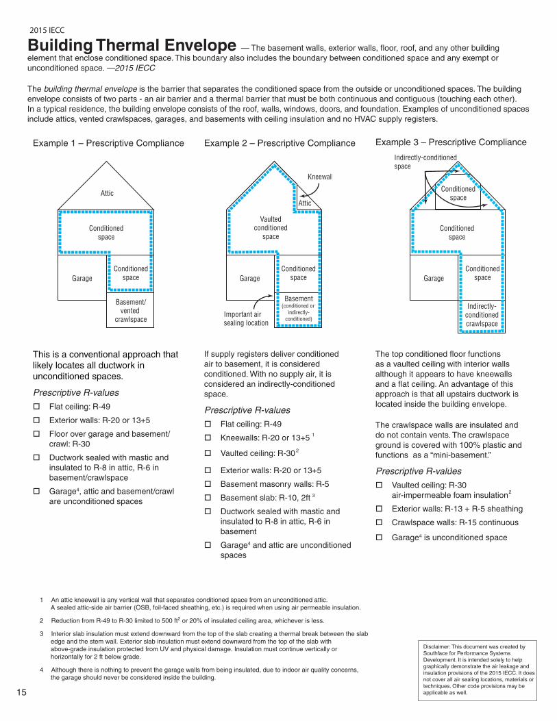
Building Thermal Envelope — The basement walls, exterior walls, floor, roof, and any other building
element that enclose conditioned space. This boundary also includes the boundary between conditioned space and any exempt or
unconditioned space. —2015 IECC
The building thermal envelope is the barrier that separates the conditioned space from the outside or unconditioned spaces. The building
envelope consists of two parts - an air barrier and a thermal barrier that must be both continuous and contiguous (touching each other).
In a typical residence, the building envelope consists of the roof, walls, windows, doors, and foundation. Examples of unconditioned spaces
include attics, vented crawlspaces, garages, and basements with ceiling insulation and no HVAC supply registers.
Example 1 – Prescriptive Compliance Example 2 – Prescriptive Compliance Example 3 – Prescriptive Compliance
This is a conventional approach that
likely locates all ductwork in
unconditioned spaces.
Prescriptive R-values
Flat ceiling: R-49
Exterior walls: R-20 or 13+5
Floor over garage and basement/
crawl: R-30
Ductwork sealed with mastic and
insulated to R-8 in attic, R-6 in
basement/crawlspace
Garage4
2
1
23
, attic and basement/crawl
are unconditioned spaces
If supply registers deliver conditioned
air to basement, it is considered
conditioned. With no supply air, it is
considered an indirectly-conditioned
space.
Prescriptive R-values
Flat ceiling: R-49
Kneewalls: R-20 or 13+5
Vaulted ceiling: R-30
Exterior walls: R-20 or 13+5
Basement masonry walls: R-5
Basement slab: R-10, 2ft
Ductwork sealed with mastic and
insulated to R-8 in attic, R-6 in
basement
Garage4 and attic are unconditioned
spaces
The top conditioned floor functions
as a vaulted ceiling with interior walls
although it appears to have kneewalls
and a flat ceiling. An advantage of this
approach is that all upstairs ductwork is
located inside the building envelope.
The crawlspace walls are insulated and
do not contain vents. The crawlspace
ground is covered with 100% plastic and
functions as a “mini-basement.”
Prescriptive R-values1
Vaulted ceiling: R-30
air-impermeable foam insulation
Exterior walls: R-13 + R-5 sheathing
Crawlspace walls: R-15 continuous
Garage4 is unconditioned space
15
Disclaimer: This document was created by
Southface for Performance Systems
Development. It is intended solely to help
graphically demonstrate the air leakage and
insulation provisions of the 2015 IECC. It does
not cover all air sealing locations, materials or
techniques. Other code provisions may be
applicable as well.
1 An attic kneewall is any vertical wall that separates conditioned space from an unconditioned attic.
A sealed attic-side air barrier (OSB, foil-faced sheathing, etc.) is required when using air permeable insulation.
2 Reduction from R-49 to R-30 limited to 500 ft2 or 20% of insulated ceiling area, whichever is less.
3 Interior slab insulation must extend downward from the top of the slab creating a thermal break between the slab
edge and the stem wall. Exterior slab insulation must extend downward from the top of the slab with
above-grade insulation protected from UV and physical damage. Insulation must continue vertically or
horizontally for 2 ft below grade.
4 Although there is nothing to prevent the garage walls from being insulated, due to indoor air quality concerns,
the garage should never be considered inside the building.
2015 IECC
Disclaimer: This document was created by
Southface for Performance Systems
Development. It is intended solely to help
graphically demonstrate the air leakage and
insulation provisions of the 2015 IECC. It does
not cover all air sealing locations, materials or
techniques. Other code provisions may be
applicable as well.16
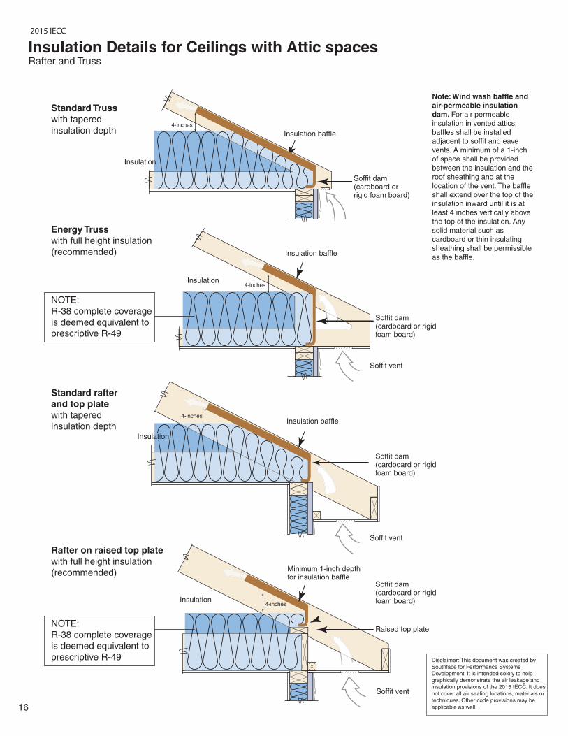
Insulation Details for Ceilings with Attic spacesRafter and Truss
Insulation baffle
Soffit vent
Soffit vent
Soffit vent
Insulation
Rafter on raised top plate
with full height insulation
(recommended)
Insulation
Insulation
Standard rafter
and top plate
with tapered
insulation depth
Energy Truss
with full height insulation
(recommended)
NOTE:
R-38 complete coverage
is deemed equivalent to
prescriptive R-49
Standard Truss
with tapered
insulation depth
Raised top plate
Soffit dam (cardboard or rigid foam board)
Soffit dam (cardboard or rigid foam board)
Soffit dam (cardboard or rigid foam board)
Soffit dam (cardboard or rigid foam board)
Insulation baffle
Insulation baffle
Note: Wind wash baffle and
air-permeable insulation
dam. For air permeable
insulation in vented attics,
baffles shall be installed
adjacent to soffit and eave
vents. A minimum of a 1-inch
of space shall be provided
between the insulation and the
roof sheathing and at the
location of the vent. The baffle
shall extend over the top of the
insulation inward until it is at
least 4 inches vertically above
the top of the insulation. Any
solid material such as
cardboard or thin insulating
sheathing shall be permissible
as the baffle.
4-inches
4-inches
4-inches
4-inches
Minimum 1-inch depth for insulation baffle
Insulation
NOTE:
R-38 complete coverage
is deemed equivalent to
prescriptive R-49
2015 IECC
17
Disclaimer: This document was created by
Southface for Performance Systems
Development. It is intended solely to help
graphically demonstrate the air leakage and
insulation provisions of the 2015 IECC. It does
not cover all air sealing locations, materials or
techniques. Other code provisions may be
applicable as well.
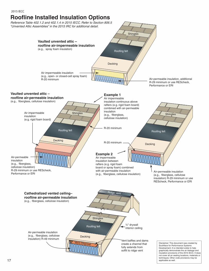
Roofline Installed Insulation OptionsReference Table 402.1.2 and 402.1.4 in 2015 IECC. Refer to Section 806.5
“Unvented Attic Assemblies” in the 2015 IRC for additional detail.
Vaulted unvented attic –
roofline air-impermeable insulation(e.g., spray foam insulation)
Vaulted unvented attic –
roofline air-permeable insulation(e.g., fiberglass, cellulose insulation)
Cathedralized vented ceiling–
roofline air-permeable insulation(e.g., fiberglass, cellulose insulation)
Air impermeable insulation
(e.g., open- or closed-cell spray foam)
R-20 minimum
Air impermeable
insulation
(e.g. rigid foam board)
Air-permeable insulation, additional
R-29 minimum or use REScheck,
Performance or ERI
Air-permeable insulation
(e.g., fiberglass, cellulose
insulation) R-29 minimum or use
REScheck, Performance or ERI
Air-permeable insulation
(e.g., fiberglass, cellulose
insulation) R-49 minimumVent baffles and dams
create a channel that
fully extends from
soffit to ridge vent
½" drywall
interior ceiling
Air-permeable
insulation
(e.g., fiberglass,
cellulose insulation)
R-29 minimum or use REScheck,
Performance or ERI
Roofing felt
Decking
Shingles
Roofing felt
Decking
Shingles
Roofing felt
Decking
Shingles
Example 1Air impermeable
insulation continuous above
rafters (e.g. rigid foam board)
combined with air-permeable
insulation
(e.g., fiberglass,
cellulose insulation)
Example 2Air impermeable
insulation between
rafters (e.g. rigid foam
board or spray foam) combined
with air-permeable insulation
(e.g., fiberglass, cellulose insulation)
R-20 minimum
R-20 minimum
Roofing felt
Decking
Shingles
Vent Channel
Ridge vent
2015 IECC
18
2015 IECC
IECC Insulation Installation Details
Wall and ceiling insulation that makes up portions of the building thermal envelope shall be installed per the manufacturer’s
instructions and IECC Table 402.4.1.1.
Two criteria affect installed insulation quality: voids/gaps (in which no insulation is present in a portion of the overall insulated surface) and compression/incomplete fill (in which the insulation does not fully fill out or extend to the desired depth).
Insulation Installation Guidelines:
Voids/Gaps o Voids or gaps in the insulation are minimized (only occasional and very small gaps)
Compression/Incomplete Fill
o Compression/Incomplete Fill for both air permeable insulation (e.g., fiberglass, cellulose) and air impermeable
insulation (e.g., spray polyurethane foam) is minimal.
Additional Wall Insulation Requirements
o All vertical air permeable insulation shall be installed in substantial contact with an air barrier on all six (6) sides. Exception: Unfinished basements and rim/band joist cavity insulation (insulation shall be restrained to stay in place). For unfinished basements, air permeable insulation and associated framing in a framed cavity wall shall be installed less than ¼” from the basement wall surface.
o Attic kneewall details – Attic kneewalls shall be insulated to a total R-value of at least R-20 cavity or 13+5 cavity and continuous. Air permeable insulation shall be installed with a fully sealed attic-side air barrier (e.g., OSB with seams caulked, rigid insulation with joints taped, etc.). Attic kneewalls with air impermeable insulation shall not require an additional attic-side air barrier.
Underfloor insulation that makes up portions of the building thermal envelope shall be installed to meet the following
guidelines.
Two criteria affect installed insulation grading: voids/ gaps (in which no insulation is present in a portion of the overall insulated surface) and compression/incomplete fill (in which the insulation does not fully fill out or extend to the desired depth).
Voids/Gaps o Voids or gaps in the insulation are minimal
Compression/Incomplete Fill
o Compression/Incomplete Fill for both air permeable insulation (e.g., fiberglass, cellulose) and air impermeable
insulation (e.g., spray polyurethane foam) is minimal.
o Air-permeable underfloor insulation shall be permanently installed against the subfloor decking. Adequate insulation supports (e.g., wire staves) for air permeable insulation shall be installed at least every 18-24”. Exception: The floor framing-cavity insulation shall be permitted to be in contact with the topside of sheathing or continuous insulation installed on the bottom side of floor framing where combined with insulation that meets or exceeds the minimum wood frame wall R-value and that extends from the bottom to the top of all perimeter floor framing members.
Disclaimer: This document was created by Southface for Performance Systems Development. It is intended solely to help graphically demonstrate the air leakage and insulation provisions of the 2015 IECC. It does not cover all air sealing locations, materials or techniques. Other code provisions may be applicable
ll
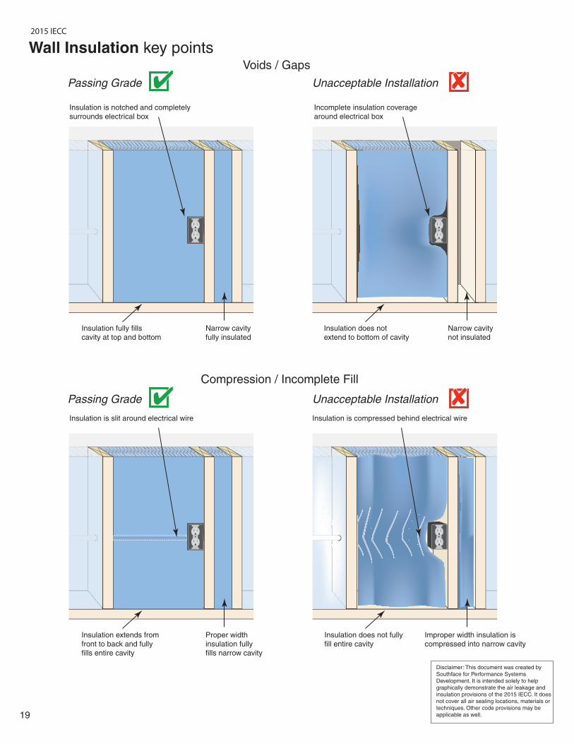
Insulation fully fills
cavity at top and bottom
Narrow cavity
fully insulated
19
Disclaimer: This document was created by
Southface for Performance Systems
Development. It is intended solely to help
graphically demonstrate the air leakage and
insulation provisions of the 2015 IECC. It does
not cover all air sealing locations, materials or
techniques. Other code provisions may be
applicable as well.
Voids / Gaps
Compression / Incomplete Fill
Insulation extends from
front to back and fully
fills entire cavity
Proper width
insulation fully
fills narrow cavity
Insulation does not fully
fill entire cavity
Improper width insulation is
compressed into narrow cavity
Insulation does not
extend to bottom of cavity
Narrow cavity
not insulated
Insulation is notched and completely
surrounds electrical box
Insulation is slit around electrical wire Insulation is compressed behind electrical wire
Incomplete insulation coverage
around electrical box
Passing Grade Unacceptable Installation
Passing Grade Unacceptable Installation
Wall Insulation key points
2015 IECC
20
Disclaimer: This document was created by
Southface for Performance Systems
Development. It is intended solely to help
graphically demonstrate the air leakage and
insulation provisions of the 2015 IECC. It does
not cover all air sealing locations, materials or
techniques. Other code provisions may be
applicable as well.
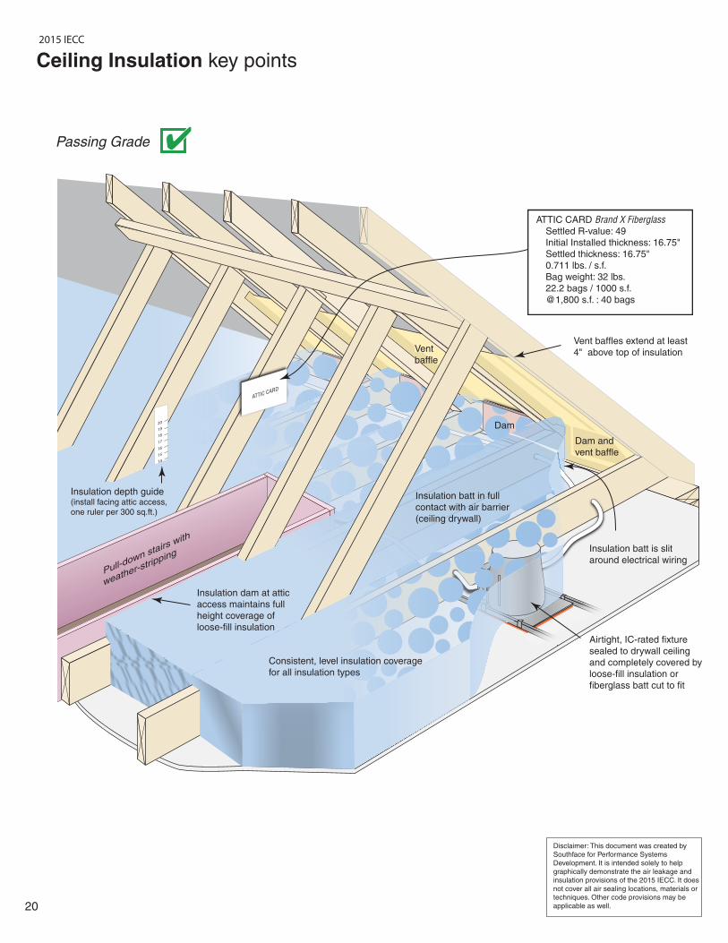
ATTIC CARD
14
15
16
17
18
19
20
Airtight, IC-rated fixture
sealed to drywall ceiling
and completely covered by
loose-fill insulation or
fiberglass batt cut to fit
Insulation batt is slit
around electrical wiring
Insulation depth guide(install facing attic access,
one ruler per 300 sq.ft.)
Pull-down stairs with
weather-strip
ping
Insulation dam at attic
access maintains full
height coverage of
loose-fill insulation
Insulation batt in full
contact with air barrier
(ceiling drywall)
Consistent, level insulation coverage
for all insulation types
Dam and
vent baffle
Dam
Vent
baffle
Vent baffles extend at least
4" above top of insulation
ATTIC CARD Brand X Fiberglass
Settled R-value: 49
Initial Installed thickness: 16.75"
Settled thickness: 16.75"
0.711 lbs. / s.f.
Bag weight: 32 lbs.
22.2 bags / 1000 s.f.
@1,800 s.f. : 40 bags
Ceiling Insulation key points
Passing Grade
2015 IECC
21
Disclaimer: This document was created by
Southface for Performance Systems
Development. It is intended solely to help
graphically demonstrate the air leakage and
insulation provisions of the 2015 IECC. It does
not cover all air sealing locations, materials or
techniques. Other code provisions may be
applicable as well.
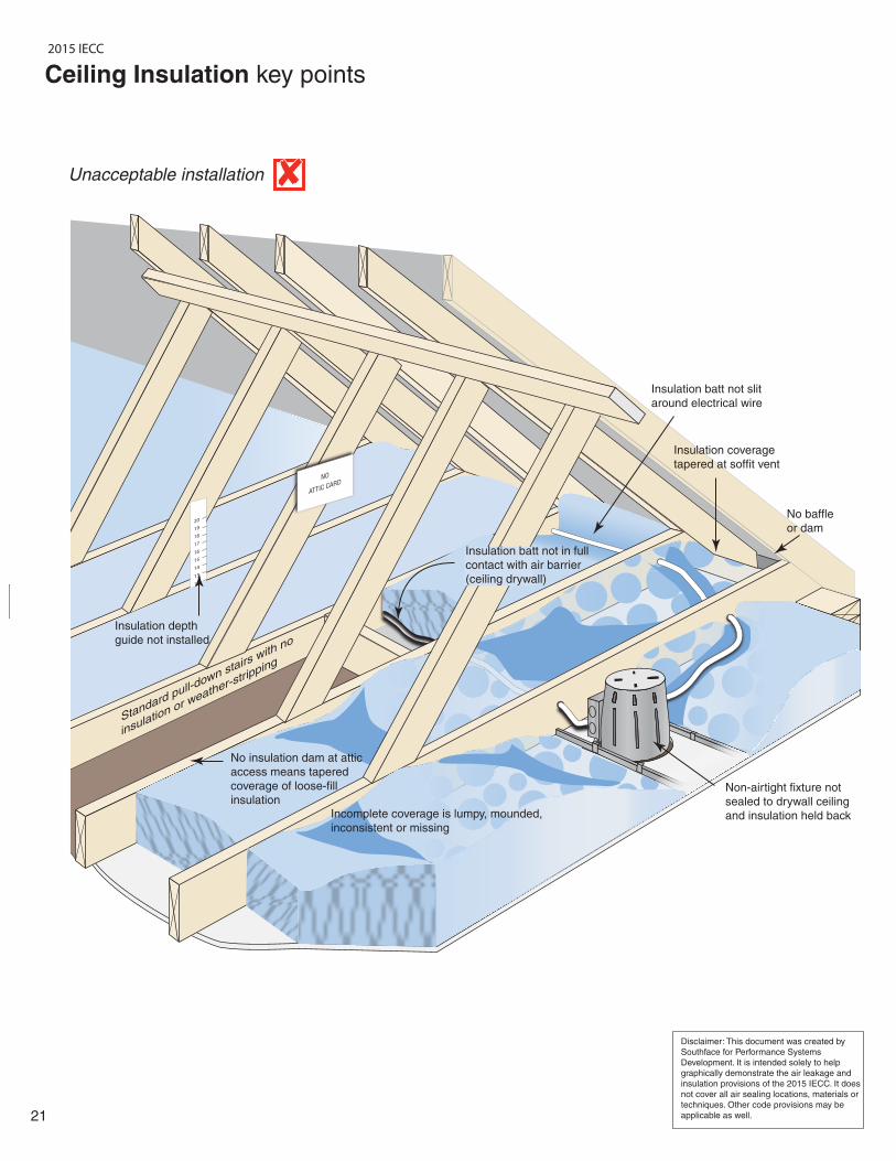
NO
ATTIC CARD
14
15
16
17
18
19
20
13
12
Non-airtight fixture not
sealed to drywall ceiling
and insulation held back
Insulation coverage
tapered at soffit vent
Insulation batt not slit
around electrical wire
Insulation depth
guide not installed
Standard pull-down stairs with no
insulation or weather-s
tripping
No insulation dam at attic
access means tapered
coverage of loose-fill
insulation
Insulation batt not in full
contact with air barrier
(ceiling drywall)
Incomplete coverage is lumpy, mounded,
inconsistent or missing
No baffle
or dam
Ceiling Insulation key points
Unacceptable installation
2015 IECC

22
Disclaimer: This document was created by
Southface for Performance Systems
Development. It is intended solely to help
graphically demonstrate the air leakage and
insulation provisions of the 2015 IECC. It does
not cover all air sealing locations, materials or
techniques. Other code provisions may be
applicable as well.
Installed insulation is in complete
contact with air barrier (subfloor)
Insulation is not installed in complete
contact with air barrier (subfloor)
Insulation coverage
is complete
Insulation is slit around plumbing
and wiring and securely fastened
with minimal compression
Insulation coverage is incomplete
due to obstructions (plumbing,
electrical, ductwork, etc.)
Insulation is compressed around
plumbing and wiring and is not
securely fastened
Wire staves
Passing Grade
Unacceptable Installation
Floor Insulation key points
2015 IECC