Embed Size (px)
Citation preview
1/18
Masonry Structural Design Competition for Civil Engineering and Architecture Students
Final Report Wednesday, May 15th, 2013
Name of University Clemson University Contact Name Sez Atamturktur, PhD Contact Title Assistant Professor Mailing Address Clemson University, Glenn Department of Civil Engineering Lowry Hall, Clemson, SC 29634-0911 Phone (864) 656-3003 Fax (864) 656-2670 E-Mail [email protected]
Masonry Design at Clemson University
In continuation of Clemson University’s longstanding history with masonry research and design,
the Glenn Department of Civil Engineering has put together a course offering students the
ability to learn about masonry design and construction. This course will help further the
awareness of masonry topics amongst students within the department, many of whom have
chosen studies in the fields of structural engineering, construction planning and materials
research. The class also offers those in related fields such as architecture and construction
science a chance to venture outside their traditional curriculum in an effort to become well-
rounded graduates more prepared for the working environment. Not only will these students
learn about the historical tradition and relevance of masonry design and construction but they
will be given chances to learn through hands-on demonstrations and activities outside the
classroom in addition to lectures given by relevant industry professionals.
The course is based on the principles laid out by the Masonry Society Joint Committee (MSJC) in
its 2011 code. The students are introduced to the historical traditions of masonry throughout
the world before being guided into modern design through coursework which involves
examples and discussion from the point of view of the practicing design engineer. Work is
assigned and students are expected to expand their knowledge of masonry throughout the
course. The topics evolve through the introduction of materials and technical notes through
simple unreinforced design to that of more advanced, reinforced shear and curtain wall design.
Through the semester the students are given examples through Allowable Strength Design
(ASD) as well as Load and Resistance Factor Design (LRFD) which together provide exposure to
both common and future design practices. Finally, the students are given a chance to research
individual topics and present a summary of their findings to the class. The final presentations
provide both a wonderful opportunity for students to practice their speaking skills as well as a
concluding discussion on more advanced topics within masonry such as acoustic considerations,
2/18
thermal design, masonry accessories and detailing, sustainability, fire resistance and impact
resiliency.
Project Purpose and Description
In an effort to supplement the topics discussed within this course, students this semester were
given the opportunity to participate in a competitive project in which they were tasked with
designing, constructing and testing masonry walls. This semester-long project pushed students
in all facets of what they learned in the course and charged them with not only the design but
also the construction of an actual masonry project. Students were given the opportunity to
compete for monetary prizes and plaques which signified the most outstanding masonry
performances.
The task called for students to design a wall of required dimensions that would be tested for
strength at the end of the semester. In addition to dimensions, students were allowed the use
of a limited quantity of reinforcing bar and grout. They were also asked to design their walls
such that 33% of the surface area was left open. Through the course of the semester students
often made progress on the project through the completion of homework assignments which
involved designing and analyzing their own masonry walls.
Class & Competition Advertising
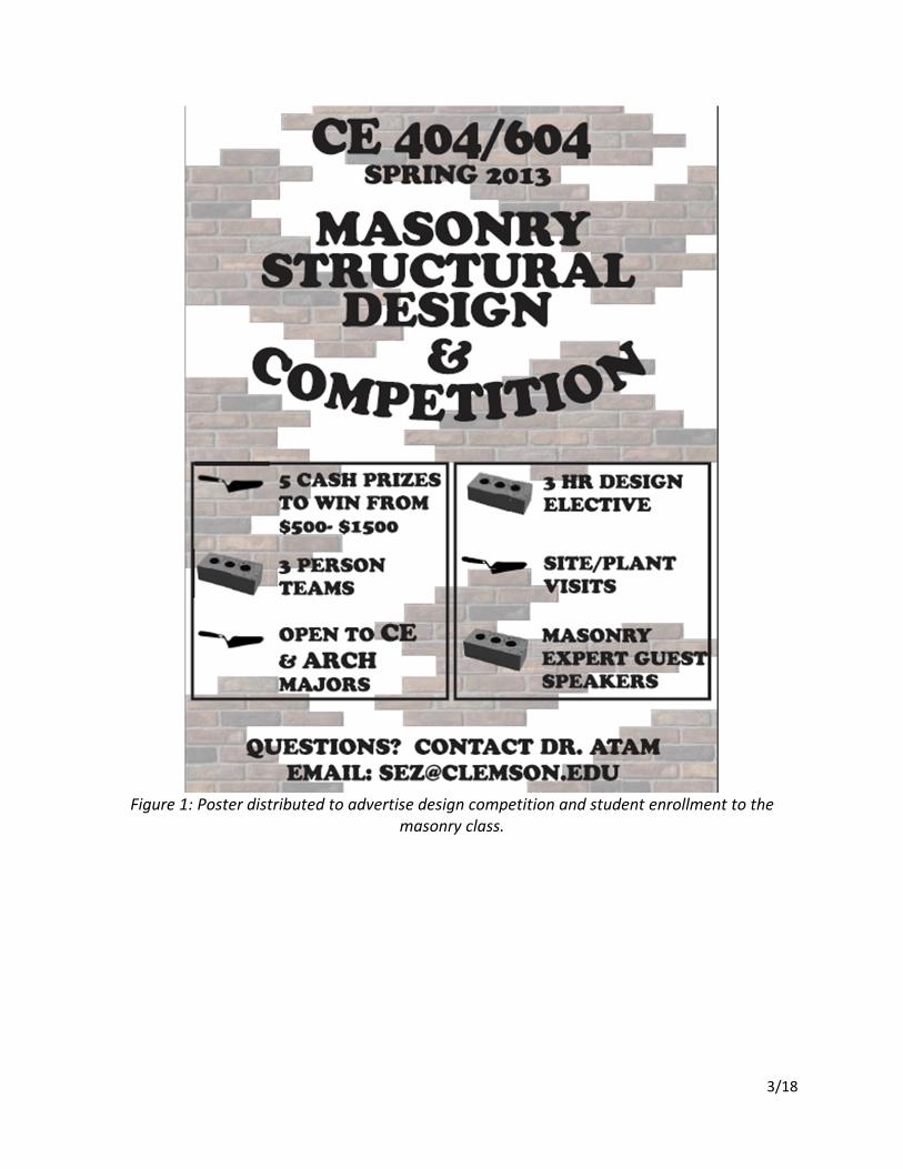
In November 2012, posters advertising the class as well as the design competition were
distributed throughout the campus – specifically in Lowry Hall (Civil Engineering department
main building) and Lee Hall (Architecture department main building). See page two for a snap-
shot of the poster (Figure 1). The spring semester began on January 9th 2013.
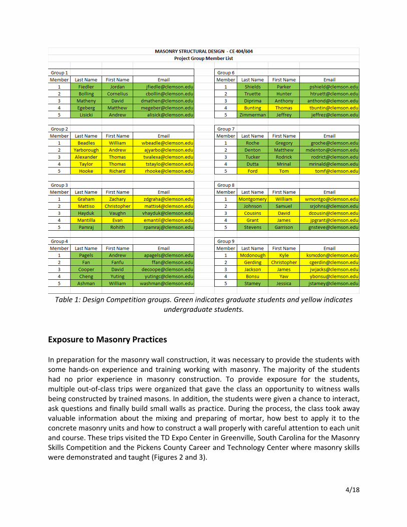
The initial classroom capacity assigned for this course was 30 students. Due to high demand,
the classroom location was modified and a total of 45 students have been accommodated.
Eighteen of these are undergraduate students enrolled in CE 404 while twenty-seven are
graduate students enrolled in CE 604. Students were asked to form groups of five to participate
in the design competition. Groups have mixed undergraduate and graduate students (Table 1).
Project groups have completed the preliminary design of their masonry wall through hand
calculations. Project teams will soon start developing numerical models of their wall in finite
element packages. Further updates regarding the progress of the design competition will be
delivered throughout the semester.
3/18
Figure 1: Poster distributed to advertise design competition and student enrollment to the
masonry class.
4/18
Table 1: Design Competition groups. Green indicates graduate students and yellow indicates
undergraduate students.
Exposure to Masonry Practices
In preparation for the masonry wall construction, it was necessary to provide the students with
some hands-on experience and training working with masonry. The majority of the students
had no prior experience in masonry construction. To provide exposure for the students,
multiple out-of-class trips were organized that gave the class an opportunity to witness walls
being constructed by trained masons. In addition, the students were given a chance to interact,
ask questions and finally build small walls as practice. During the process, the class took away
valuable information about the mixing and preparing of mortar, how best to apply it to the
concrete masonry units and how to construct a wall properly with careful attention to each unit
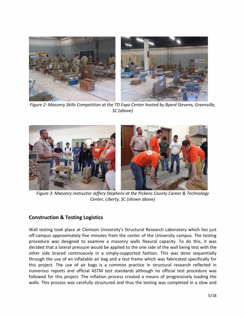
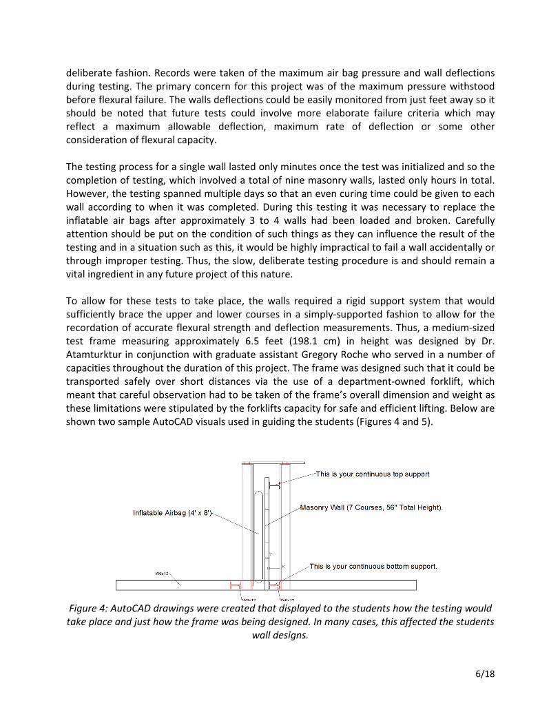
and course. These trips visited the TD Expo Center in Greenville, South Carolina for the Masonry
Skills Competition and the Pickens County Career and Technology Center where masonry skills
were demonstrated and taught (Figures 2 and 3).
5/18
Figure 2: Masonry Skills Competition at the TD Expo Center hosted by Byard Stevens, Greenville,
SC (above)
Figure 3: Masonry instructor Jeffery Stephens at the Pickens County Career & Technology
Center, Liberty, SC (shown above)
Construction & Testing Logistics
Wall testing took place at Clemson University’s Structural Research Laboratory which lies just
off-campus approximately five minutes from the center of the University campus. The testing
procedure was designed to examine a masonry walls flexural capacity. To do this, it was
decided that a lateral pressure would be applied to the one side of the wall being test with the
other side braced continuously in a simply-supported fashion. This was done sequentially
through the use of an inflatable air bag and a test frame which was fabricated specifically for
this project. The use of air bags is a common practice in structural research reflected in
numerous reports and official ASTM test standards although no official test procedure was
followed for this project. The inflation process created a means of progressively loading the
walls. This process was carefully structured and thus the testing was completed in a slow and
6/18
deliberate fashion. Records were taken of the maximum air bag pressure and wall deflections
during testing. The primary concern for this project was of the maximum pressure withstood
before flexural failure. The walls deflections could be easily monitored from just feet away so it
should be noted that future tests could involve more elaborate failure criteria which may
reflect a maximum allowable deflection, maximum rate of deflection or some other
consideration of flexural capacity.
The testing process for a single wall lasted only minutes once the test was initialized and so the
completion of testing, which involved a total of nine masonry walls, lasted only hours in total.
However, the testing spanned multiple days so that an even curing time could be given to each
wall according to when it was completed. During this testing it was necessary to replace the
inflatable air bags after approximately 3 to 4 walls had been loaded and broken. Carefully
attention should be put on the condition of such things as they can influence the result of the
testing and in a situation such as this, it would be highly impractical to fail a wall accidentally or
through improper testing. Thus, the slow, deliberate testing procedure is and should remain a
vital ingredient in any future project of this nature.
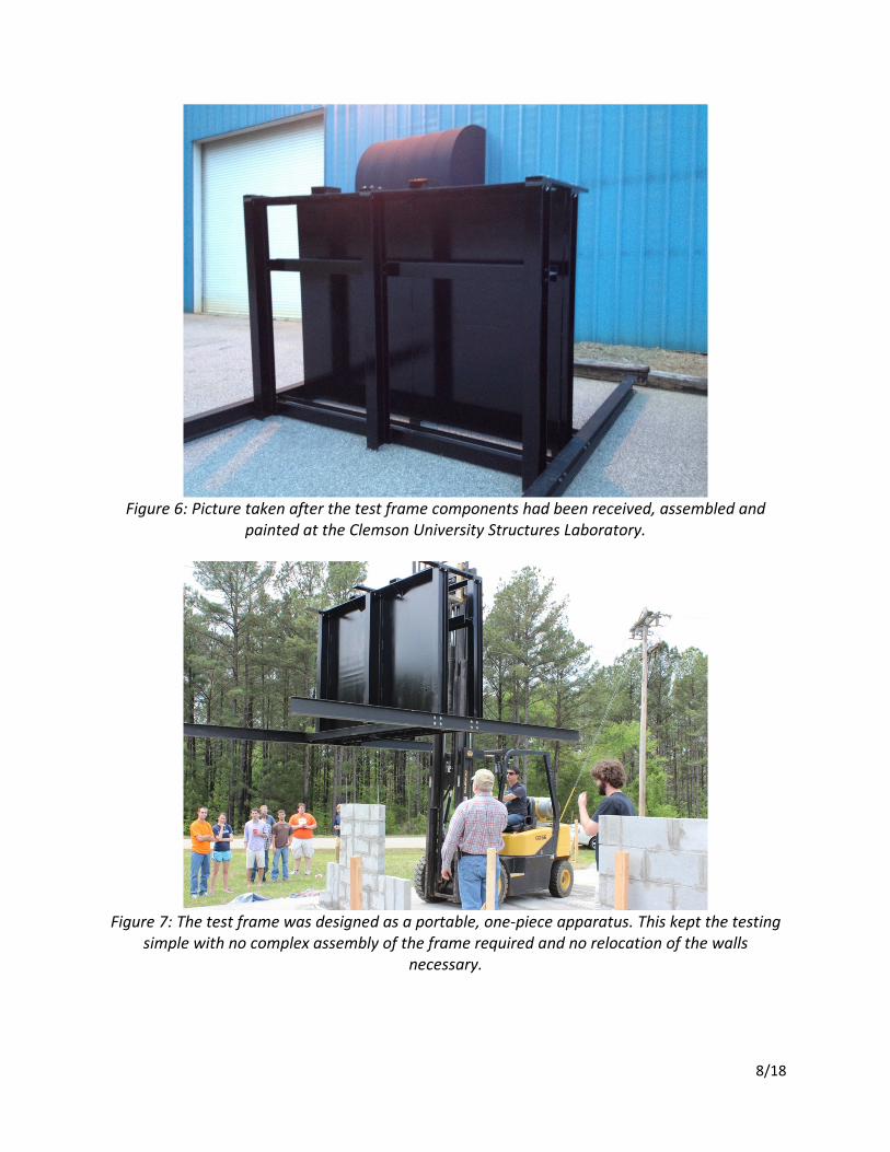
To allow for these tests to take place, the walls required a rigid support system that would
sufficiently brace the upper and lower courses in a simply-supported fashion to allow for the
recordation of accurate flexural strength and deflection measurements. Thus, a medium-sized
test frame measuring approximately 6.5 feet (198.1 cm) in height was designed by Dr.
Atamturktur in conjunction with graduate assistant Gregory Roche who served in a number of
capacities throughout the duration of this project. The frame was designed such that it could be
transported safely over short distances via the use of a department-owned forklift, which
meant that careful observation had to be taken of the frame’s overall dimension and weight as
these limitations were stipulated by the forklifts capacity for safe and efficient lifting. Below are
shown two sample AutoCAD visuals used in guiding the students (Figures 4 and 5).
Figure 4: AutoCAD drawings were created that displayed to the students how the testing would
take place and just how the frame was being designed. In many cases, this affected the students
wall designs.
7/18
Figure 5: Another figure shown to the students. It demonstrates the continuous lateral bracing
of the wall (outlined in red) and where the lateral pressure would be applied (outlined in blue).
The students were also tasked with removing 33% of the surface area without compromising the
outer 88” x 56” dimensions.
Design & Construction of Testing Frame
The creation of a portable test frame was necessary in that it ensured the walls would not have
to be moved individually which would have been a very delicate and dangerous process in
which the walls structural capacity could easily have been comprised, particularly in such a
competition where each wall’s geometry was encouraged to be unique. There are obvious
safety risks as well in this type of process so it was decided that the wall testing should take
place without any relocation demands upon the walls either during or after construction.
Conceptual input and consultation on the general design of the test frame was also provided by
the department’s technical supervisor Danny Metz and his staff. Much of their role within the
department is in the supervision and technical support of projects such as this. Careful
consideration should, and in this case was, given to the abilities and limitations of any
department’s resourcefulness in the design and fabrication of research- or project-oriented
demands. In this instance, the construction of the frame was handled by the Seneca-based
fabrication Blue Ridge Welding and Machining who accurately interpreted both hand-drawn
structural sketches as well as detailed AutoCAD drawings of the test frame. Special attention
was given within the design and outline of the frame to its future use in similar applications
both for class projects as well as masonry research. The completed frame will prove to be a
departmental asset for years to come. See Figure 6-8 below.
8/18
Figure 6: Picture taken after the test frame components had been received, assembled and
painted at the Clemson University Structures Laboratory.
Figure 7: The test frame was designed as a portable, one-piece apparatus. This kept the testing
simple with no complex assembly of the frame required and no relocation of the walls
necessary.
9/18
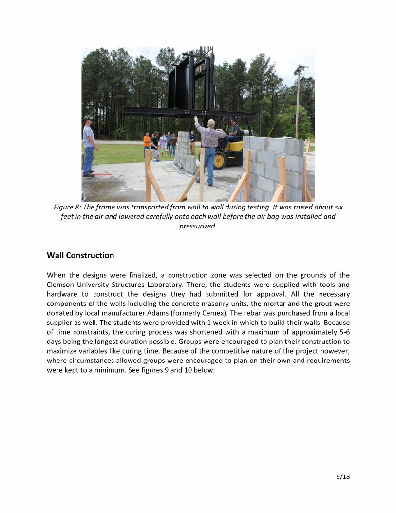
Figure 8: The frame was transported from wall to wall during testing. It was raised about six
feet in the air and lowered carefully onto each wall before the air bag was installed and
pressurized.
Wall Construction
When the designs were finalized, a construction zone was selected on the grounds of the
Clemson University Structures Laboratory. There, the students were supplied with tools and
hardware to construct the designs they had submitted for approval. All the necessary
components of the walls including the concrete masonry units, the mortar and the grout were
donated by local manufacturer Adams (formerly Cemex). The rebar was purchased from a local
supplier as well. The students were provided with 1 week in which to build their walls. Because
of time constraints, the curing process was shortened with a maximum of approximately 5-6
days being the longest duration possible. Groups were encouraged to plan their construction to
maximize variables like curing time. Because of the competitive nature of the project however,
where circumstances allowed groups were encouraged to plan on their own and requirements
were kept to a minimum. See figures 9 and 10 below.
10/18
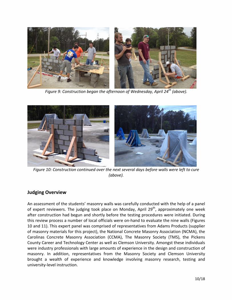
Figure 9: Construction began the afternoon of Wednesday, April 24
th (above).
Figure 10: Construction continued over the next several days before walls were left to cure
(above).
Judging Overview
An assessment of the students’ masonry walls was carefully conducted with the help of a panel
of expert reviewers. The judging took place on Monday, April 29th, approximately one week
after construction had begun and shortly before the testing procedures were initiated. During
this review process a number of local officials were on-hand to evaluate the nine walls (Figures
10 and 11). This expert panel was comprised of representatives from Adams Products (supplier
of masonry materials for this project), the National Concrete Masonry Association (NCMA), the
Carolinas Concrete Masonry Association (CCMA), The Masonry Society (TMS), the Pickens
County Career and Technology Center as well as Clemson University. Amongst these individuals
were industry professionals with large amounts of experience in the design and construction of
masonry. In addition, representatives from the Masonry Society and Clemson University
brought a wealth of experience and knowledge involving masonry research, testing and
university-level instruction.
11/18
The results from the judging were combined with the results of the testing as well as the
students predictions to tabulate and overall group score. The best three overall group scores
were recognized with certificates and congratulations as well as prize money provided through
the donations from the National Concrete Masonry Association’s Education and Research
Foundation. Monetary prizes in the amounts of $1,500, $1,000 and $500 were awarded to the
first, second and third place groups, respectively in accordance with their overall project score.
The primary goal for the student competitors in this project was in constructing a wall of
maximum performance under lateral loading and so $1,000 was also awarded to the group
whose wall had achieved the highest ratings when tested for flexural strength. This seemed a
very sensible reward as the focus of the project was directed almost entirely towards this end
from the students end. In addition, a $1000 reward was given to the group whose flexural
capacity prediction had most closely matched the actual test results of their wall. This reflected
the group’s ability to carefully consider, predict and estimate the various parameters which
influenced their walls ultimate capacity in addition to the structural techniques taught in the
course. The effects involved were largely unknown to the groups, at least in detail, and so
careful research and consideration was necessary in making accurate adjustments to the typical
structural engineering techniques involved in practical masonry design. It was considered
important to reward the diligent efforts of the most exemplary group in this category.
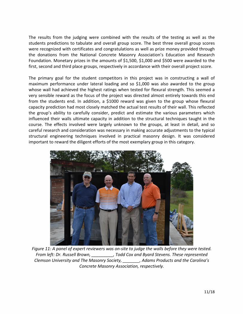
Figure 11: A panel of expert reviewers was on-site to judge the walls before they were tested.
From left: Dr. Russell Brown, _________, Todd Cox and Byard Stevens. These represented
Clemson University and The Masonry Society, _______, Adams Products and the Carolina’s
Concrete Masonry Association, respectively.
12/18
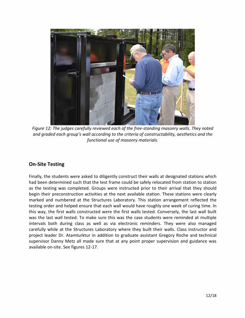
Figure 12: The judges carefully reviewed each of the free-standing masonry walls. They noted
and graded each group’s wall according to the criteria of constructability, aesthetics and the
functional use of masonry materials.
On-Site Testing
Finally, the students were asked to diligently construct their walls at designated stations which
had been determined such that the test frame could be safely relocated from station to station
as the testing was completed. Groups were instructed prior to their arrival that they should
begin their preconstruction activities at the next available station. These stations were clearly
marked and numbered at the Structures Laboratory. This station arrangement reflected the
testing order and helped ensure that each wall would have roughly one week of curing time. In
this way, the first walls constructed were the first walls tested. Conversely, the last wall built
was the last wall tested. To make sure this was the case students were reminded at multiple
intervals both during class as well as via electronic reminders. They were also managed
carefully while at the Structures Laboratory where they built their walls. Class instructor and
project leader Dr. Atamturktur in addition to graduate assistant Gregory Roche and technical
supervisor Danny Metz all made sure that at any point proper supervision and guidance was
available on-site. See figures 12-17.
13/18
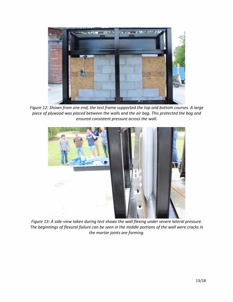
Figure 12: Shown from one end, the test frame supported the top and bottom courses. A large
piece of plywood was placed between the walls and the air bag. This protected the bag and
ensured consistent pressure across the wall.
Figure 13: A side-view taken during test shows the wall flexing under severe lateral pressure.
The beginnings of flexural failure can be seen in the middle portions of the wall were cracks in
the mortar joints are forming.
14/18
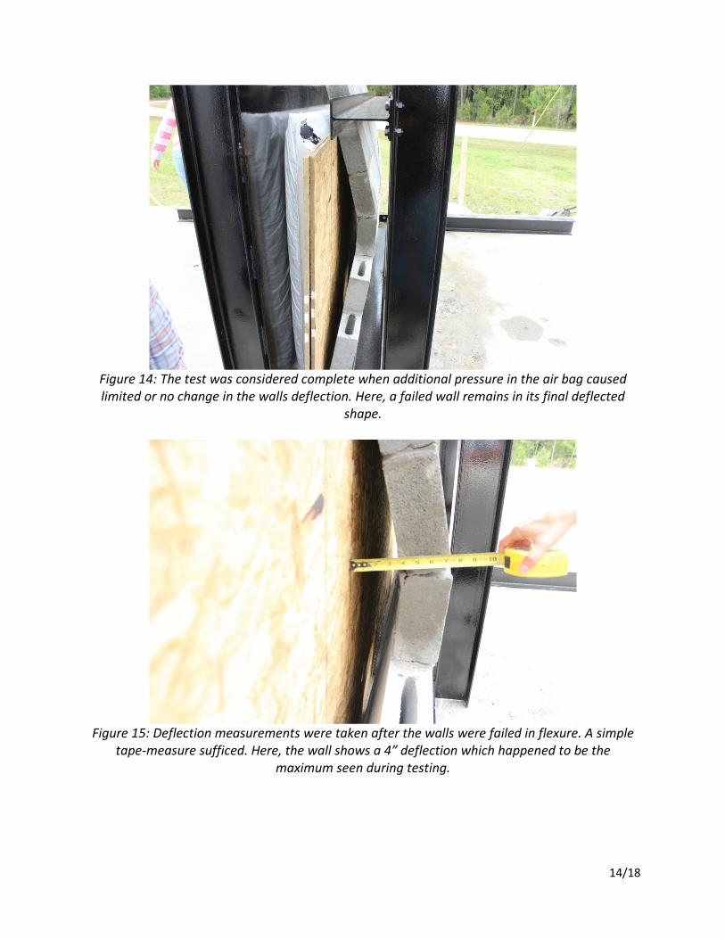
Figure 14: The test was considered complete when additional pressure in the air bag caused
limited or no change in the walls deflection. Here, a failed wall remains in its final deflected
shape.
Figure 15: Deflection measurements were taken after the walls were failed in flexure. A simple
tape-measure sufficed. Here, the wall shows a 4” deflection which happened to be the
maximum seen during testing.
15/18
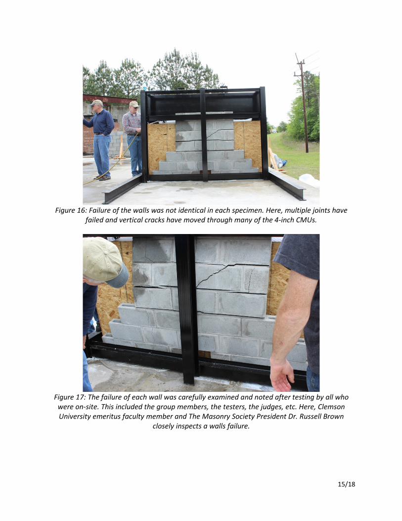
Figure 16: Failure of the walls was not identical in each specimen. Here, multiple joints have
failed and vertical cracks have moved through many of the 4-inch CMUs.
Figure 17: The failure of each wall was carefully examined and noted after testing by all who
were on-site. This included the group members, the testers, the judges, etc. Here, Clemson
University emeritus faculty member and The Masonry Society President Dr. Russell Brown
closely inspects a walls failure.
16/18
Group Scoring
The walls were evaluated according to a rubric with five primary areas of focus. Most important
in evaluating each wall was its structural performance during the out-of-plane load tests which
were conducted the week following construction. These tests were completed over 3 days to
balance curing times and to allow students some flexibility during exam week to attend the
scheduled wall tests.
The breaking strength of each wall contributed to a total of 35% of the overall group score. This
was the highest weighting given to any of the five criteria. This high weighting was given
because it reflected the structural design developed by the students, the craftsmanship of the
construction and the competitive creativity which was encouraged throughout the project.
To complement the structural performance of their walls, groups were asked to estimate what
they thought to be their walls actual breaking strength. Students began by estimating their
walls capacity according to MSJC 2011 code requirements. To reflect the nature of the project,
groups were encouraged to adjust their predicted strength based on the many variables that
would have an effect during testing. Student construction, limited curing time and conservative
code requirements all contributed to variances in the predicted strengths which students
estimated according to their own predictions. The predictions each group made were measured
against the test data. The importance of this category reflected a variety of project goals.
Students were able to measure the accuracy of their calculations, the impact of masonry
craftsmanship and the basis for many of the MSJC code requirements.
The final three judging criteria were given equal weight. Each was worth 15% of the overall
group score. These were the constructability of the walls, the aesthetics and craftsmanship
displayed as well as the functional use of masonry materials. The first of these, the
constructability, measured how efficiently the wall could be built. The complexity of the unit
layout, the void spacing in the wall and the construction time were all considered as factors in
this measurement. The second criteria, which measured the quality and aesthetics of each wall
was based on a visual inspection done following construction by the judging panel. The visual
appeal of the wall design was also considered in this category. The final criteria which involved
the functional use of materials reflected the thoughtfulness of the design and the practicality of
the construction. The placement of rebar and the groups’ use of masonry units were important
factors in this category.
Test Results
Table 1 shows the scoring associated with the first two categories. This involved the flexural
testing capacity (category 1) as well as the strength prediction accuracy of the group (category
2). Highlighted are the two groups (1 &3) which tied for the maximum wall capacity during
testing and the group (9) whose predictions most closely matched the actual strength of their
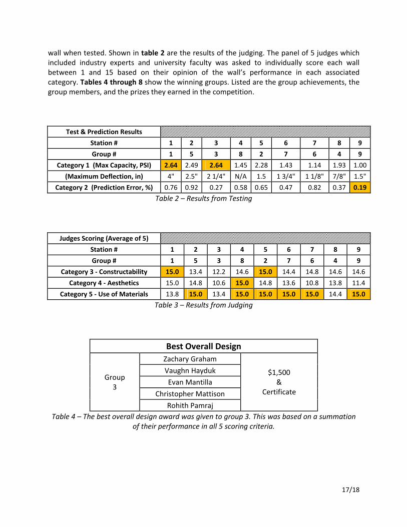
17/18
wall when tested. Shown in table 2 are the results of the judging. The panel of 5 judges which
included industry experts and university faculty was asked to individually score each wall
between 1 and 15 based on their opinion of the wall’s performance in each associated
category. Tables 4 through 8 show the winning groups. Listed are the group achievements, the
group members, and the prizes they earned in the competition.
Test & Prediction Results
Station # 1 2 3 4 5 6 7 8 9
Group # 1 5 3 8 2 7 6 4 9
Category 1 (Max Capacity, PSI) 2.64 2.49 2.64 1.45 2.28 1.43 1.14 1.93 1.00
(Maximum Deflection, in) 4" 2.5" 2 1/4" N/A 1.5 1 3/4" 1 1/8" 7/8" 1.5"
Category 2 (Prediction Error, %) 0.76 0.92 0.27 0.58 0.65 0.47 0.82 0.37 0.19
Table 2 – Results from Testing
Judges Scoring (Average of 5)
Station # 1 2 3 4 5 6 7 8 9
Group # 1 5 3 8 2 7 6 4 9
Category 3 - Constructability 15.0 13.4 12.2 14.6 15.0 14.4 14.8 14.6 14.6
Category 4 - Aesthetics 15.0 14.8 10.6 15.0 14.8 13.6 10.8 13.8 11.4
Category 5 - Use of Materials 13.8 15.0 13.4 15.0 15.0 15.0 15.0 14.4 15.0
Table 3 – Results from Judging
Best Overall Design
Group
3
Zachary Graham
$1,500
&
Certificate
Vaughn Hayduk
Evan Mantilla
Christopher Mattison
Rohith Pamraj
Table 4 – The best overall design award was given to group 3. This was based on a summation
of their performance in all 5 scoring criteria.
18/18
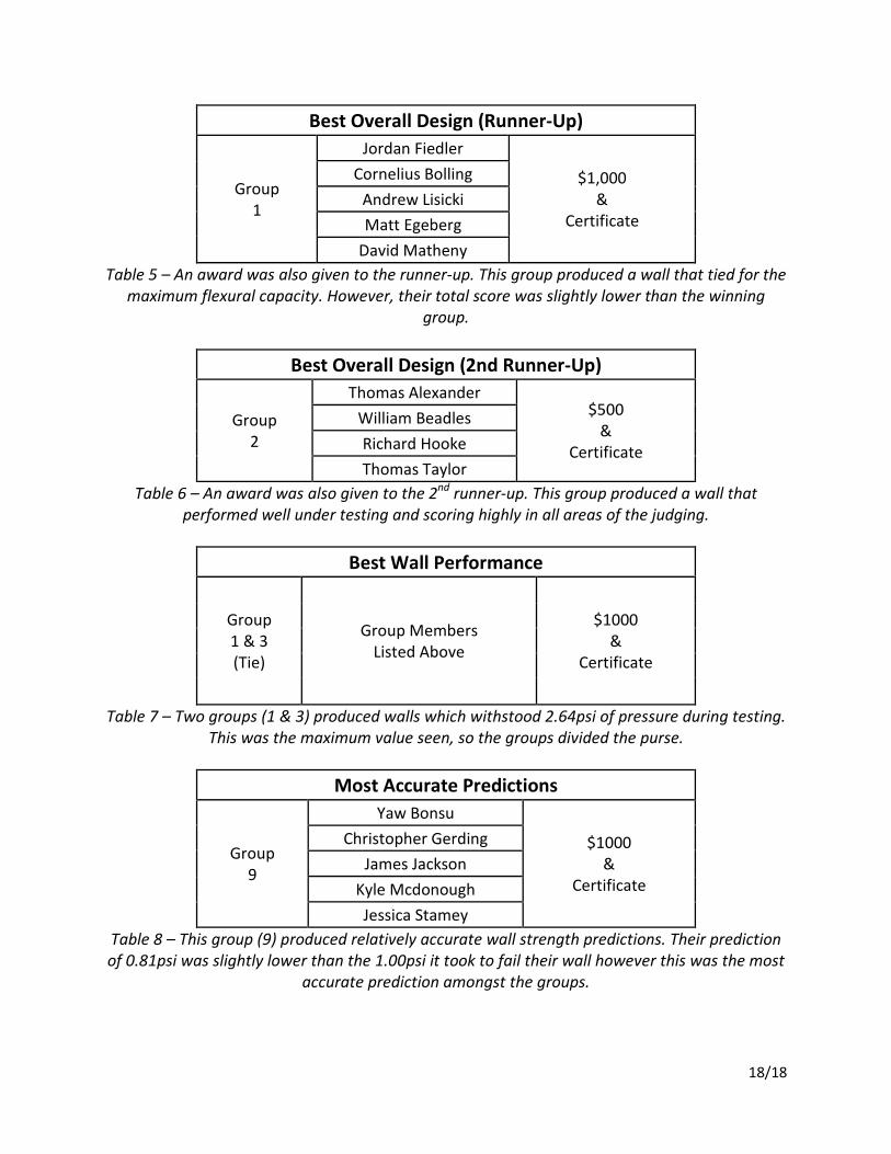
Best Overall Design (Runner-Up)
Group
1
Jordan Fiedler
$1,000
&
Certificate
Cornelius Bolling
Andrew Lisicki
Matt Egeberg
David Matheny
Table 5 – An award was also given to the runner-up. This group produced a wall that tied for the
maximum flexural capacity. However, their total score was slightly lower than the winning
group.
Best Overall Design (2nd Runner-Up)
Group
2
Thomas Alexander $500
&
Certificate
William Beadles
Richard Hooke
Thomas Taylor
Table 6 – An award was also given to the 2nd
runner-up. This group produced a wall that
performed well under testing and scoring highly in all areas of the judging.
Best Wall Performance
Group
1 & 3
(Tie)
Group Members
Listed Above
$1000
&
Certificate
Table 7 – Two groups (1 & 3) produced walls which withstood 2.64psi of pressure during testing.
This was the maximum value seen, so the groups divided the purse.
Most Accurate Predictions
Group
9
Yaw Bonsu
$1000
&
Certificate
Christopher Gerding
James Jackson
Kyle Mcdonough
Jessica Stamey
Table 8 – This group (9) produced relatively accurate wall strength predictions. Their prediction
of 0.81psi was slightly lower than the 1.00psi it took to fail their wall however this was the most
accurate prediction amongst the groups.