Embed Size (px)
Citation preview

JOMO KENYATTA UNIVERSITY
OF
AGRICULTURE AND TECHNOLOGY
DEPARTMENT OF ELECTRICAL & ELECTRONIC ENGINEERING
P.O. BOX 62000 - 00200, NAIROBI
TEL: (067) - 52181-4, 52711 FAX: (067) – 52220
Email: [email protected]
FINAL YEAR PROJECT REPORT
JEFFER MASIKA WANJALA
EN271-C007-0046/2010
SUPERVISOR: MR AMOS KIVUVA
TITLE: MICROCONTROLLER BASED MUSICAL WATER FOUNTAIN
A Final Year Project Report submitted to the Department of Electrical and Electronic
Engineering in partial fulfillment of the requirements for the award of a Bachelor of Science
Degree in Electrical and Electronic Engineering.
JAN 2016

ii
DECLARATION
I, JEFFER MASIKA WANJALA, of registration number EN272-C007-0046/2010, declare
hereby that this proposal is my original work and that it has neither been submitted nor
transferred by any other student for a degree or any other course in this institution or any other
institution of learning. However, reference was made to documents already published by other
people as shown under the reference section.
Signature…………………………… Date………………………..
JEFFER MASIKA WANJALA
EN272-C007-0046/2010
CERTIFICATION
This project has been proposed, developed, supervised and submitted for examination with my
approval as the University supervisor.
Signature……………………………. Date…………………………………..
MR. AMOS KIVUVA
PROJECT SUPERVISOR
DEPARTMENT OF ELECTRICAL AND ELECTRONICS ENGINEERING

iii
ACKNOWLEDGEMENT
I would like to thank the Almighty God for bringing me this far in my undergraduate studies. I
would also like to thank my project supervisor, Mr. Amos Kivuva for his informative support
and guidance needed to make this project a success. Special appreciation goes to my friends and
family for their motivation and support.

iv
ABSTRACT
Fountains that just make patterns with water jets have now developed into multimedia shows
with music, light, and special effects. A musical fountain with synchronized water and music
creates an atmosphere that can be exciting or romantic. The aim of this project is to create
musical-fountain shows in real time from a variety of music sources. We will develop a
prototype in which the system can analyze an audio stream in real time, and the onsets the
system detects immediately modify the fountain show. Although implementing a real-time
technique poses several difficulties, such as noise, we’re exploring more-elaborate techniques
such as real-time beat tracking. The goal is to let users perform a musical-fountain show
immediately based on the music from an onlooker’s portable MP3 player or a real musical
performance.
This project incorporates a microcontroller generally controls the water pumps, the solenoid
valves, the lights, and the equipment that moves the nozzles. The microcontroller is interfaced
with a computer, usually through a serial port with RS-232, which is a standard of serial binary
data connecting. The blocks on the timeline specify when the control units are turned on and off,
and the system converts them into control data and sends them to microcontroller channel. This
assures that the scenarios intelligent musical-fountain-authoring system (Imfas) generates can be
directly exported to real fountain hardware without converting them into specific control system
formats. We will implement a software module to control the microcontroller.

v
TABLE OF CONTENT
DECLARATION ............................................................................................................................................. ii
CERTIFICATION ........................................................................................................................................... ii
ACKNOWLEDGEMENT ................................................................................................................................ iii
ABSTRACT .................................................................................................................................................. iv
TABLE OF CONTENT .................................................................................................................................. v
LIST OF FIGURES ....................................................................................................................................... vii
LIST OF TABLES ........................................................................................................................................ viii
CHAPTER ONE ............................................................................................................................................ 9
1.0 Introduction .......................................................................................................................................... 9
1.1 Problem Statement .............................................................................................................................. 9
1.2 Justification ........................................................................................................................................ 10
1.3 Aim and Objectives ............................................................................................................................ 10
1.3.1 General Objective ........................................................................................................................... 10
1.3.2 Specific Objectives ......................................................................................................................... 10
CHAPTER TWO .......................................................................................................................................... 11
2.0 Literature Review ............................................................................................................................... 11
2.1. Alternating Fountains........................................................................................................................ 11
2.2. Air and Steam Assisted Fountains ................................................................................................... 14
2.3. Interactive Fountains ........................................................................................................................ 15
2.4. Variable Spray or Dancing Fountains ............................................................................................... 17
2.5. Fire on Fountains .............................................................................................................................. 21
2.6. Laminar Stream Fountains ............................................................................................................... 23
2.7 Musical fountain ................................................................................................................................. 25
3 CHAPTER THREE ................................................................................................................................... 26
3.0 DEISGN ANALYSIS .......................................................................................................................... 26
3.1 POWER SUPPLY .............................................................................................................................. 26

vi
Frequency ranger selector....................................................................................................................... 29
AMPLIFIER .............................................................................................................................................. 32
COMPLETE CIRCUIT DIAGRAM ........................................................................................................... 34
CIRCUIT OPERATION ............................................................................................................................ 34
CHAPTER FOUR ........................................................................................................................................ 35
4.0 RESULTS AND DISCUSSIONS ....................................................................................................... 35
4.1 General Objective .............................................................................................................................. 35
4.2 Specific Objectives ............................................................................................................................ 35
4. 3TEST RESULTS ................................................................................................................................ 36
CHAPTER FIVE .......................................................................................................................................... 37
5.0 CONCLUSION .................................................................................................................................... 37
5.1 RECOMMENDATIONS ...................................................................................................................... 37
CHAPTER 6: PROJECT TIME PLAN ......................................................................................................... 38
CHAPTER SEVEN: BUDGET ..................................................................................................................... 39
7.0 COSTING .......................................................................................................................................... 39
REFERENCES ............................................................................................................................................ 40
APPENDIX .................................................................................................................................................. 41
PROGRAM .............................................................................................................................................. 41

vii
LIST OF FIGURES
Figure 1: Hero’s singing bird fountain (1st century) .................................................................................... 12
Figure 2: Al-Jazari alternating fountain (12th century), redrawn based on a figure in reference (Hill, 1984).
.................................................................................................................................................................... 13
Figure 3:“Big-Mouth” mechanism in Hellbrunn Palace, Salzburg, Austria (17th century), scanned from
reference (Helminger). ................................................................................................................................ 14
Figure 4: Air-powered fountain, scanned from US patent (Woodward, 1913) ............................................ 15
Figure 5:Air-powered fountain, scanned from US patent # 4,852,801 ....................................................... 16
Figure 6 User-activated fountain, scanned from US patent # 4,817,312 .................................................... 17
Figure 7: Movable Nozzles, scanned from US patent # 3,907,204 ............................................................ 18
Figure 8: Variable-play fountain, scanned from US patent # 5,524,822 ..................................................... 19
Figure 9: Two-degree freedom nozzle apparatus scanned from US patent # 6,053,423. .......................... 20
Figure 10: Water and fire designed by Pejack and Eubanks, 2003. Note the separated flame in the photo
on the left. Photos by Ed Pejack. ................................................................................................................ 21
Figure 11: Colored flame fountain apparatus, scanned from US patent # 4,858,826 ................................ 22
Figure 12: Water on fire appearing water display, scanned from US patent # 5,961,042. ......................... 23
Figure 13: Laminar stream nozzle, scanned from (Fuller M., 1989). .......................................................... 24

viii
LIST OF TABLES
Table 1: PROJECT TIME PLAN ................................................................................................................. 38
Table 2: BUDGET ...................................................................................................................................... 39

9
CHAPTER ONE
1.0 Introduction
Water fountains have been used for thousands of years for climatic control, beautification,
entertainment, and as a means for relaxation. Among the most popular fountains have been those
that incorporate elements of surprise and/or special effects. These fountains elegantly combine
engineering and artistic features. Due to the inherent multidisciplinary nature of fountains and
their appeal to the general public, there exists a great potential to have our own programmed
logic musical fountain.
After watching some Kenyan fountain shows for several days, I noticed that the scenarios were
always the same. The fountain’s operators confirmed that they do not change the scenario only
because of budget constraints. Regardless of how spectacular a fountain show is, if the scenarios
remain the same, the show can lose its appeal. So, we will come up with an intelligent musical
fountain to improve this situation.
Because1 scenario generation depends on audio-signal analysis, including better or different
analysis techniques should lead to improved, or more versatile, scenario generation. For
example, the system could use voice-separation techniques—which try to isolate a singer’s voice
from an instrumental accompaniment—to detect a vocal passage’s beginning and end. This
would provide additional onsets that the system could use to synchronize fountains’ jets.
Probability-based approaches such as a Bayesian network tend not to produce scenarios with
large-scale coherence (for example, a scenario in which all the control units are turned on in
sequence). We’re now exploring additional scenario-generation methods based on patterns to
support these more structured scenarios. We believe that an intelligent musical fountain could
reduce fountain costs, which should allow more changes.
1.1 Problem Statement
As spectators we greatly appreciate water fountain because they make our environments
beautiful and exciting, but problem with them is that they give same scenario. Watching the
same thing all the time becomes boring and unappealing. Coming up with another fountain
structure to solve this problem is expensive. Skilled programmer can spend days or even weeks
creating a new performance, but this still will be expensive. So, they rarely change the routines,
and they repeat a limited program every day.
To curb this problem we are going to come up with a control system which is well programmed
to change water fountain scenario depending with the type of music is fed into the input. This
will create an atmosphere which will be more exciting and romantic to the viewers.

10
1.2 Justification
Water fountain which are used to solve the problem of beautification and to attract event
attendees in entertainment industries are non- musical and just employ a block mechanism to
allow water to ooze out and pumps has to be manually switched on and off, or if automated they
do not produce deferent scenarios thus a musical control system manned to curd this.
This system provides a microcontroller generally controls the water pumps, the solenoid valves,
the lights, and the equipment that moves the nozzles. The microcontroller is interfaced with a
computer, usually through a serial port with RS-232, which is a standard of serial binary data
connecting, or a LAN. The blocks on the timeline specify when the control units are turned on
and off, and the system converts them into control data and sends them to each microcontroller
channel. This assures that the scenarios intelligent musical fountain generates can be directly
exported to real fountain hardware without converting them into specific control system formats.
Software module will be implemented to control several kinds of microcontroller.
1.3 Aim and Objectives
1.3.1 General Objective
Design a small water fountain that will change scenario depending on the music input.
1.3.2 Specific Objectives
To let users perform a musical-fountain show immediately based on the music from an
onlooker’s portable MP3, MP4 player, CDs or a real musical performance.
To develop a prototype in which the system can analyze an audio stream in real time, and the
onsets the system detects immediately modify the fountain show.
To develop an interface between water fountain and the microcontroller control system to be
able to produce deferent scenario depending with the type of input music.
To implement the control algorithm in the model with the help of the microcontroller
system.

11
CHAPTER TWO
2.0 Literature Review
The earliest record of fountains dates back to 4000 BC in Iran. For thousands of years fountains
were gravity fed - either directly from a running source of water such as a river that was located
at a higher elevation, or from a holding tank built just behind the fountain. Simple
devices were used in ingenious setups to provide special effects such as creating sound and
motion to surprise onlookers.
Around the 20th
century the availability of electric pumps and later on the advancement
of control technology brought even more ingenuity to the design of fountains with special
effects. Today, with state-of-the-art computer controlled technology, we can witness
monumental fountain installations requiring 7.5 MW of power, this fountain can utilizes more
than 1200 nozzles that shoot out water jets to heights reaching 240 feet in the air. And 300 of
those jets (nozzles) move back and forth to dance in synch with music for the enjoyment of
visitors. We will use earliest fountain and blend in elements of engineering and art in elegant
ways to come up with sophisticated versions.
2.1. Alternating Fountains
Hero of Alexandria (1stcentury) was perhaps the first designer of fountains with special effects.
Siphons (U-shaped or concentric) served as the main part responsible for creation of
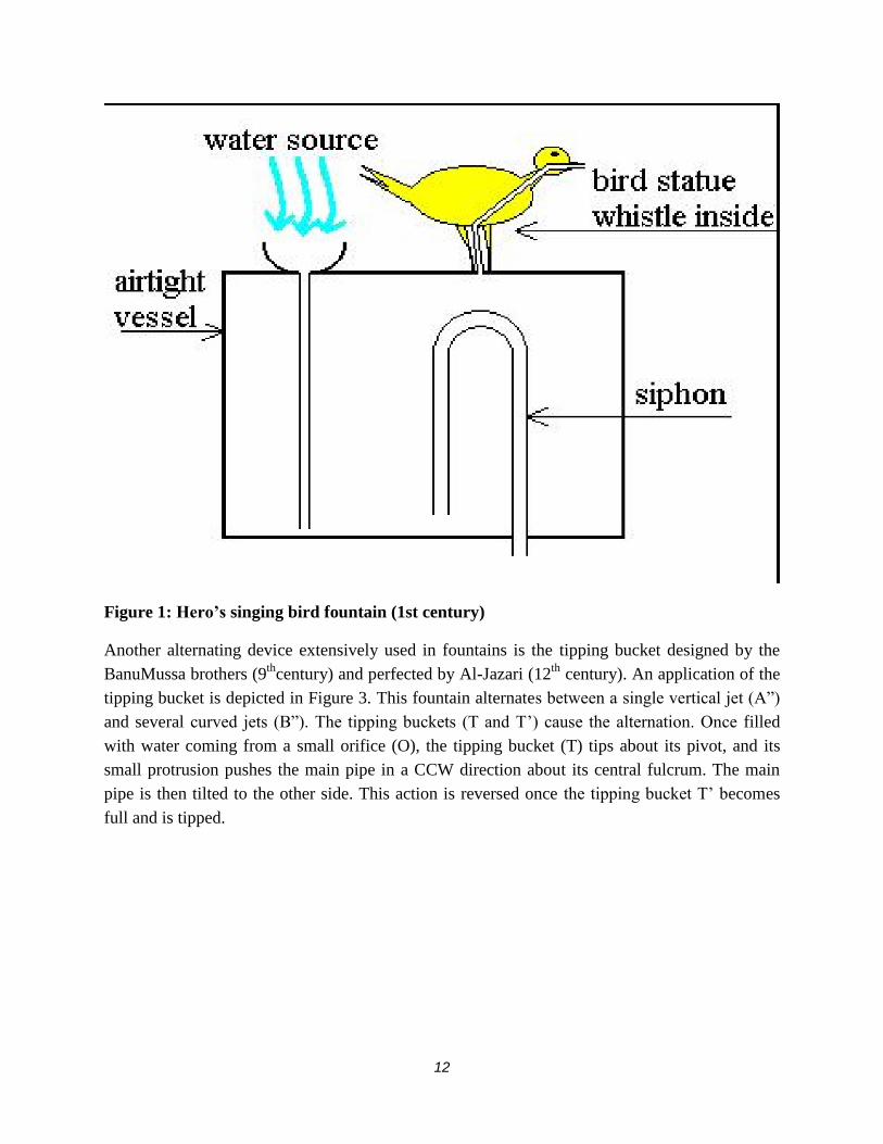
special effects in his fountains. One of Hero’s designs is schematically shown in Figure 1. In
this fountain, after the water level rises and covers the siphon inlet, its continued flow
into an otherwise airtight vessel pushes the existing air out through a whistle within a bird’s
statue. The whistling sound appears to be coming from the bird and thus surprises the onlookers.
The siphon starts discharging the water as soon as the water level in the vessel reaches the top of
the siphon. Then the bird is silenced as air is sucked into the vessel due to partial
vacuum created by discharging the water through the siphon. This continues until the
water level in the vessel reaches below the siphon. Air is let in and the siphoning is
terminated. The whistling period starts again shortly thereafter. In other words, the siphon is
responsible for the whistling-silence cycle. In more elaborate setups, Hero masterfully used
several siphons in conjunction with other mechanical devices such as floats, cables and pulleys
to create sound and motion. Siphons are still used today for the creation of special effects in
fountains; e.g., see US patent # 5,381,956, where a U-shaped siphon is used in a self-activating
falling water display. (Hero, 1971)
12
Figure 1: Hero’s singing bird fountain (1st century)
Another alternating device extensively used in fountains is the tipping bucket designed by the
BanuMussa brothers (9th
century) and perfected by Al-Jazari (12th
century). An application of the
tipping bucket is depicted in Figure 3. This fountain alternates between a single vertical jet (A‖)
and several curved jets (B‖). The tipping buckets (T and T’) cause the alternation. Once filled
with water coming from a small orifice (O), the tipping bucket (T) tips about its pivot, and its
small protrusion pushes the main pipe in a CCW direction about its central fulcrum. The main
pipe is then tilted to the other side. This action is reversed once the tipping bucket T’ becomes
full and is tipped.

13
Figure 2: Al-Jazari alternating fountain (12th century), redrawn based on a figure in
reference (Hill, 1984).
The tipping bucket idea was used in the ―Big-Mouth‖ water display in the Hellbrunn
Palace, which was designed by architect Solari (17th
century). Many other water features with
special effects are still working in Hellbrunn Palace today. The ―Big-Mouth‖ mechanism is
shown in Figure 3. Note that the lower jaw is a tipping bucket. And when full of water, it
tips over, grabbing a bent rod that actuates the tongue and the eyelids. Once emptied, the
lower jaw returns to its closed position and the above cycle is repeated as long as there is water
flow to the mechanism. The use of the tipping bucket is recurring even in modern-day patents.
An example can be seen in US patent # 5,367,805, where the action of a hidden tipping bucket
actuates the handle of an old-fashion pump, creating a motion whose cause is non-obvious to
onlookers.

14
Figure 3:“Big-Mouth” mechanism in Hellbrunn Palace, Salzburg, Austria (17th century),
scanned from reference (Helminger).
2.2. Air and Steam Assisted Fountains
Figure 4 is taken from US patent # 151,003 that describes an air-assisted fountain for
indoor use. A hand pump was used to pressurize air in the water reservoir (part A), which
allowed for a steady jet of water from the nozzle (part D). Steam has also been used to drive
water jets in small fountains for indoor use

15
Figure 4: Air-powered fountain, scanned from US patent (Woodward, 1913)
Fuller and Robinson invented a modern version of air-powered water display. As shown
in Figure 5, taken from US patent # 4,852,801, water is allowed to fill in the nozzle body (part #
50) and then a blast of compressed air (coming from part 34) shoots most of the water out of the
nozzle to great heights. This effect could be produced by pressurized water as well but it would
cost much more to pressurize water than use compressed air. Fuller and his co-inventor made
improvements to the their air-powered fountains for example, by using computer controlled
proportional valves, water jets with varying heights could be obtained.(Fuller, 1989)(Fuller, Air
Powered Water Display Nozzle Unit, 1996)
2.3. Interactive Fountains
Interactive fountains are those in which the water flow (show) is initiated by some action of a
user. The earliest interactive fountain, designed by Hero of Alexandria, was a water dispenser. A
user would drop a coin into a slot at the top of the dispenser. The coin would fall on a lever arm
actuating a valve momentarily to let out water. Another interactive fountain was the ―Organ
Fountain‖ in Villa d’Este (16th
century). A water wheel was used to operate bellows to pump air
for the organ. The organ would start playing as visitors stepped on certain pavement
stone blocks near the fountain. A mechanism was hidden below those blocks that activated the
organ keys when stepped on.

16
Figure 5:Air-powered fountain, scanned from US patent # 4,852,801
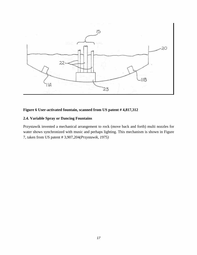
Fuller and Robinson disclosed a user-activated fountain, where sound sensors are installed on the
bottom of a fountain pool. The fountain is normally off. Figure 6, taken from patent 4, 817, 312,
shows the general layout of the nozzles (parts 22) and sensors (parts 11A & B). After a coin is
tossed into the pool, the sensors pick up the sound waves generated by the coin. By
gating (triangulation of) the sensor outputs, the area of the pool in which the coin was tossed can
be identified. The nozzle action can then be directed to that area of the pool. After a
predetermined time the fountain is turned off and then it would be ready for the next coin.
(Fuller M. a., 1989)
17
Figure 6 User-activated fountain, scanned from US patent # 4,817,312
2.4. Variable Spray or Dancing Fountains
Przystawik invented a mechanical arrangement to rock (move back and forth) multi nozzles for
water shows synchronized with music and perhaps lighting. This mechanism is shown in Figure
7, taken from US patent # 3,907,204(Przystawik, 1975)

18
Figure 7: Movable Nozzles, scanned from US patent # 3,907,204
Opposing streams were used in an invention by Simmons to produce pleasing water displays. As
shown in Figure 9, taken from US patent # 5,524,822, two separate streams(flowing through
parts 92 and 93) enter conduits (part 91) from opposite ends. The two streams (Simmons,
1966) combine and produce jets coming out from the openings as shown. According to the
inventor, one can control the jets’ direction and flow rate by varying the pressures and/or flow
rates of the streams

19
Figure 8: Variable-play fountain, scanned from US patent # 5,524,822
Jacobsen et al. invented a two-degree freedom apparatus capable of rocking nozzles along
perpendicular directions. Figure 9, taken from US patent # 6,053,423, show their invention.
There are two motors involved and the whole apparatus is placed on a platform (not shown) that
could be moved in and out of the water as desired during a water show. Dynamic shows can be
produced with computerized control of the motors in synch with accompanied music/lighting.
(Jacobsen, 2000)

20
Figure 9: Two-degree freedom nozzle apparatus scanned from US patent # 6,053,423.

21
2.5. Fire on Fountains
Integrating fire into fountains is an intriguing task. Designers of fountains have been able to
produce such integration. Both gas and liquid fuels have been used. Pejack and Eubanks
designed a small-scale decorative fountain with eight water jets surrounding a propane
(fuel) jet. Figure 10 displays two photographs of their fountain. Slight wind in the proximity of
the fountain causes interesting fluctuation and separation in the flame. Flow rates of propane and
water are adjustable via appropriate valves. (Pejack, 2003)
Figure 10: Water and fire designed by Pejack and Eubanks, 2003. Note the separated flame
in the photo on the left. Photos by Ed Pejack.
Robinson and Fuller invented a fountain system capable of illuminating water jets with
colored flames. Figure 11, taken from US patent # 4,858,826, shows the details of their
colored flame apparatus. The flame colors are produced by solutions of various metallic
salts injected (from parts 34) into the main burner (part 22). Note the water nozzles are

22
numbered 20 in the figure. Various sensors are used for safety; for example, the fuel is
shut when the flame is extinguished by whatever reason. (Robinson, 1989)
Figure 11: Colored flame fountain apparatus, scanned from US patent # 4,858,826
In U.S. Patent # 5,961,042, Doyle describes a system of water nozzles fitted with a gas line for
producing flames. The schematic of his invention is shown in Figure 12. Sensors are used for
safety. The inverted U-shaped section of the gas line (part 54) reaches sufficiently above the
surface of the pool to assure that the gas line does not fill with water when the gas is turned off.

23
Placing several of these nozzles in a row in a pool can create dramatic water shows.
Safety features include sensor (part 68). (Doyle, 1999)
Figure 12: Water on fire appearing water display, scanned from US patent # 5,961,042.
2.6. Laminar Stream Fountains
A popular fountain, the laminar stream nozzle, has been installed in theme parks and shopping
centers since the 1980s. Fuller received a patent for this nozzle. Figure 13, taken from US
patent # 4,795,092, shows a cutout view of the laminar nozzle. It is made of a cylinder with a
tangential inlet and a knife-edge orifice outlet (part 12). The screens (parts 19 and 22) and
honeycomb or drinking straws (part 21) significantly reduce the turbulence and cause the exiting
stream to be laminar.

24
Figure 13: Laminar stream nozzle, scanned from (Fuller M., 1989).
In a follow up invention, Fuller and Robinson devised a quick diversion method by which the
laminar stream could be controllably terminated to give the effect of slicing the stream
perpendicularly to its longitudinal axis. Further improvement to the original laminar nozzle
included adding a mounting assembly for the laminar nozzle 22-24. The assembly is used for
changing the angle and repositioning of the nozzle so that the laminar stream appears to emanate
from a fixed location at different angles, which allows varying the characteristics of the arch-like
laminar stream in dynamic displays. (Fuller M. a., 1989)

25
2.7 Musical fountain
In this project the fountain should have several outlets or nozzles to allow the formation of
different characters by using water jets from selected outlets. These outlets would be individually
controllable. The characters should be easily created, arranged, and sequenced to produce
pleasing water displays as per the music input. Furthermore, the fountain would be made from
readily available materials and components, although minor fabrication is permissible. And, it
would run on the ordinary line power (240VAC in the Kenya) and be safe to operate .As
indicated above, the outlets are to be individually controlled; this feature can be easily met by
utilizing a microcontroller. Today, there are a wide variety of inexpensive microcontrollers for
various applications in industry, consumer products, and hobbies. Some of the microcontrollers
are offered in kit form so that the user can quickly set the mup for the application at hand.

26
3 CHAPTER THREE
3.0 DEISGN ANALYSIS
3.1 POWER SUPPLY
This consist of a step down transformer which steps down the mains voltage from 240V to
12vac, a full wave bridge rectifier which converts the ac voltage from transformer to dc, a shunt
capacitor filter which smoothens the rectified dc voltage and a voltage regulator which regulates
the smoothened dc voltage.
12Vdc
5Vdc
D3
D2
D4
D1
240Vac
I/P
GND
T120to1
+
C1
+
C2
IN
COM
OUT
IC1
Fig 3.1 power supply circuit diagram
The circuit operates on a current of 2A. The transformer employed should be rated 500mA.
TX power = TX output voltage X TX output current
= 12 X 2A
= 24VA
TX1 is a 240 to 12V 24VA step-down transformer.
27
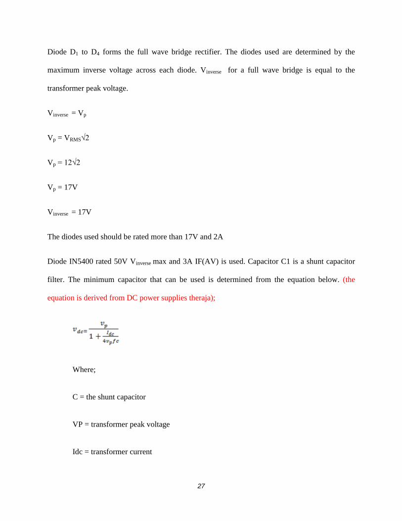
Diode D1 to D4 forms the full wave bridge rectifier. The diodes used are determined by the
maximum inverse voltage across each diode. Vinverse for a full wave bridge is equal to the
transformer peak voltage.
Vinverse = Vp
Vp = VRMS√2
Vp = 12√2
Vp = 17V
Vinverse = 17V
The diodes used should be rated more than 17V and 2A
Diode IN5400 rated 50V Vinverse max and 3A IF(AV) is used. Capacitor C1 is a shunt capacitor
filter. The minimum capacitor that can be used is determined from the equation below. (the
equation is derived from DC power supplies theraja);
Where;
C = the shunt capacitor
VP = transformer peak voltage
Idc = transformer current

28
F = supply frequency
Vdc = 12V
Vp = 17V
Idc = 2A
F = 50Hz
12 (3400C + 2) = 57800C
40800C +24= 57800C
57800C – 40800C = 24
17000C = 24
C=1412 µF
C = 2200µF standard capacitor
29
C1 = 2200µF 25V
The capacitor is rated 25V since the voltage across its terminal will increase to Vp
IC1 is the voltage regulator which regulates the voltage to attain 5V. The logic gates employed
will operate on a current of 1A.IC L7805 rated 5V and 1A is selected from the catalogue. The
regulator datasheet recommends a 10µF shunt capacitor filter be connected at the regulator
output. C2=10µF
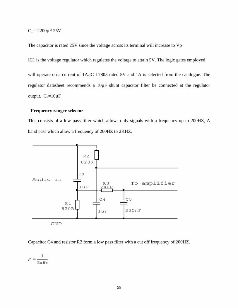
Frequency ranger selector
This consists of a low pass filter which allows only signals with a frequency up to 200HZ, A
band pass which allow a frequency of 200HZ to 2KHZ.
To amplifierAudio in
GND
C5
330nF
R1
820R
C3
1uF
C4
1uF
R2
820R
R3240R
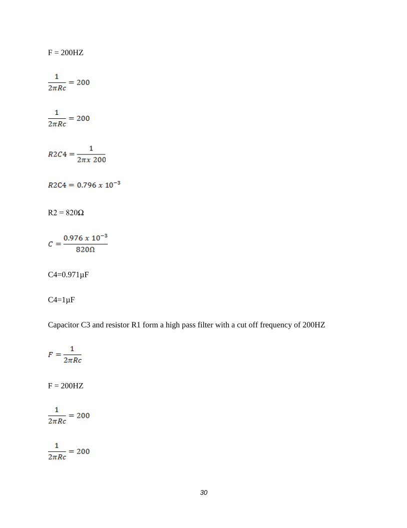
Capacitor C4 and resistor R2 form a low pass filter with a cut off frequency of 200HZ.
30
F = 200HZ
R2 = 820Ω
C4=0.971µF
C4=1µF
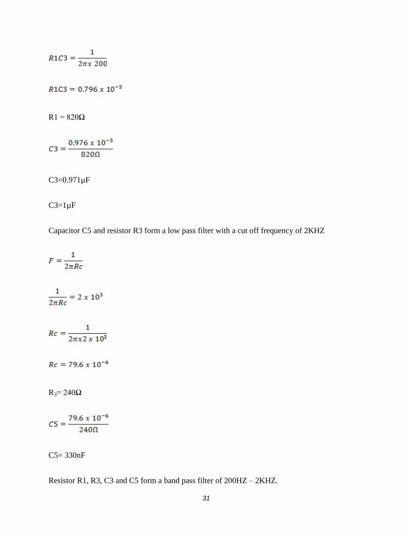
Capacitor C3 and resistor R1 form a high pass filter with a cut off frequency of 200HZ
F = 200HZ
31
R1 = 820Ω
C3=0.971µF
C3=1µF
Capacitor C5 and resistor R3 form a low pass filter with a cut off frequency of 2KHZ
R3= 240Ω
C5= 330nF
Resistor R1, R3, C3 and C5 form a band pass filter of 200HZ – 2KHZ.

32
AMPLIFIER
This consists of two audio amplifiers.
+5V
GND
To microcontrollerFrom frequency
selector
R410R
R510R
+IC2
LM386
RV110k 40%
+
IC3
LM386
RV210k 40%
+
C610uF
+
C910uF
+
C710uF
+
C810uF
C10
473
C11
473
IC2 and IC3 are audio amplifiers. The amplifier employed is LM386 which has a gain of 200

33

34
COMPLETE CIRCUIT DIAGRAM
D3
D2
D4
D1
240Vac
I/P
7
8
1
ATMEGA328
IC4
2210
9
2120
23
24
19
18
17
14
13
12
11
AVCC
PD5
PD6
PD7
PB0
A1
A0PB5
PB3
PB4
VREF
AGND
OSC
OSC
RST
GND
VCC
PIC
C5
330nF
C11
473
C10
473
Q3NDMOS
Q2NDMOS
Q1NDMOS
LED4
LED3
LED2
LED1
+
C810uF
M1
SL1
12V
D7
1N4001
SL2
12VD6
1N4001
D5
1N4001
+
C710uF
+
C910uF
+
C610uF
C13
30pF
C12
30pF
XTAL1
16MHZ
RV210k 40%
+
IC3
LM386
RV110k 40%
C4
1uF
C3
1uF
+IC2
LM386
J1
T120to1
+
C1
1000uF +
C2
10uF
IN
COM
OUT
IC178L05
R3820R
R510R
R410R
R12270R
R11270R
R10270R
R9270R
R6270R
R7270R
R8270R
R2
820R
R1
820R

Bsc in Electrical & Electronics Engineering Page 34
CIRCUIT OPERATION
The transformer steps down the mains voltage from 240V to 12V. The full wave bridge rectifier
formed by D1 to D4 convert the a.c voltage to eliminate the ripples. The voltage regulator IC1
regulates the rectified voltage to attain a fixed 5V output; to supply the microcontroller.
The crystal oscillator generates the operating frequency to the microcontroller.
The two audio amplifiers are used to amplify the audio signal from the computer. The upper
amplifier amplifies frequencies under 200HZ. The lower amplifier amplifies signals with
frequency above 200HZ. The microcontroller converts the analogue voltage from the amplifies
to digital and compares the amplitude. Then the microcontroller switches on the corresponding
valve according to the signal amplitude. When any valve is on the microcontroller switches on
the pump to unsure the water is pumped back to the storage. When all the valves are off the
microcontroller switches off the pump. This is to ensure it does not pump air.

Bsc in Electrical & Electronics Engineering Page 35
CHAPTER FOUR
4.0 RESULTS AND DISCUSSIONS
4.1 General Objective
Design a small water fountain that will change scenario depending on the input music from
variety of sources.
4.2 Specific Objectives
Users can perform a musical-fountain show immediately based on the music from an
onlooker’s portable MP3, MP4 player, CDs or a real musical performance.
Developed a prototype in which the system can analyze an audio stream in real time, and the
onsets the system detects immediately modify the fountain show.
Developed an interface between water fountain and the microcontroller control system to be
able to produce deferent scenario depending with the type of input music.
Implemented the control algorithm in the model with the help of the microcontroller
system.
The aim of this project is to create musical-fountain shows in real time from a variety of music
sources. We will develop a prototype in which the system can analyze an audio stream in real
time, and the onsets the system detects immediately modify the fountain show. Although
implementing a real-time technique poses several difficulties, such as noise, we’re exploring
more-elaborate techniques such as real-time beat tracking. The goal is to let users perform a
musical-fountain show immediately based on the music from an onlooker’s portable MP3 player
or a real musical performance.

Bsc in Electrical & Electronics Engineering Page 36
4. 3TEST RESULTS
No. Test point Expected Measure
1 Input voltage 240Vac 235Vac
2 Transformer output 12Vac 12Vac
3 Rectifier output 12Vdc 15Vdc
4 Regulator output 5Vdc 4.96Vdc
5 Microcontroller output 5Vdc
6 Output to solenoid valve when off 0Vdc 0Vdc
7 Output to solenoid valve when on 12Vdc 13Vdc
8 Output to pump 12Vdc 13Vdc

Bsc in Electrical & Electronics Engineering Page 37
CHAPTER FIVE
5.0 CONCLUSION
The project operated as expected since as the no music was fed to the circuit all the valves
remained closed. When music is played the system opened the valves according to beats and
switched on the pump to return the water. When all valves were closed the system switched off
the pump too.
5.1 RECOMMENDATIONS
To improve the system further a large pump can be connected to the system via a relay circuit
which can switch 240V.
Also the data can be filtered using a computer and the beats send to the microcontroller via the
serial port or USB port.
Bsc in Electrical & Electronics Engineering Page 38
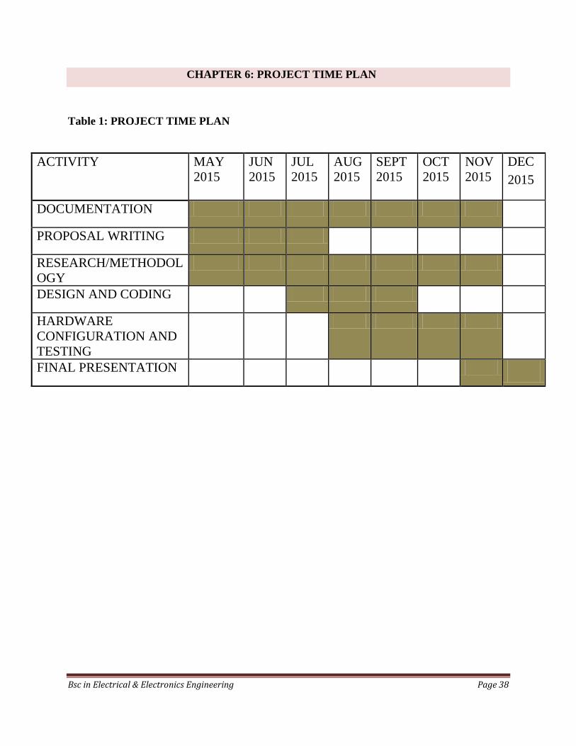
CHAPTER 6: PROJECT TIME PLAN
Table 1: PROJECT TIME PLAN
ACTIVITY MAY
2015
JUN
2015
JUL
2015
AUG
2015
SEPT
2015
OCT
2015
NOV
2015
DEC
2015
DOCUMENTATION
PROPOSAL WRITING
RESEARCH/METHODOL
OGY
DESIGN AND CODING
HARDWARE
CONFIGURATION AND
TESTING
FINAL PRESENTATION

Bsc in Electrical & Electronics Engineering Page 39
CHAPTER SEVEN: BUDGET
Table 2: BUDGET
7.0 COSTING
No. Item Quantity Cost Amount
1 Transformer 240Vac-12Vac, 24VA 1 1,000 1,000
2 Diodes 7 10 70
3 Capacitor 13 20 260
4 Resistors 12 10 120
5 Solenoid valve 2 2,500 5,000
6 Pump 1 3,000 3,000
7 Mosfets 3 100 300
8 IC socket 28 pin 1 50 50
9 ICs
L7805
LM386
ATMEGA328
1
2
1
50
300
1,500
50
600
1,500
10 Power code 1 50 50
11 Circuit board big 1 100 100
12 Casing big 1 500 500
13 Solder wire 4M 30 120
14 Connecting and looping wire 4M 20 80
15 Connectors 2 50 100
Total 12,900

Bsc in Electrical & Electronics Engineering Page 40
REFERENCES
[1] Hero, The Pneumatics of Hero of Alexandria, London, 1971.
[2] D. R. Hill, A History of Engineering in Classical and Medieval Times, Open Court
Publishing , 1984.
[3] B. a. S. S. Helminger, Hellbrunn: A Guide through the Trick Fountains, the Park and
Palace,‖.
[4] N. P. a. B. L. Woodward, Fountain for Decorative Purpose, 1913.
[5] M. a. R. Fuller, Air Powered Water Displays, U.S. Patent # 4,852,801., 1989.
[6] M. a. R. Fuller, Air Powered Water Display Nozzle Unit, us: U.S. Patent # 5,480,094, 1996.
[7] M. a. R. A. Fuller, User Activated Fountain Display, U.S: U.S. Patent # 4,817,312., 1989.
[8] G. Przystawik, Musical Display Fountain, U.S: U.S. Patent # 3,907,204, 1975.
[9] T. R. Simmons, Apparatus for ProducingVariable-Play Fountain Sprays, U.S: U.S. Patent #
5,524,822., 1966.
[10] S. C. S. F. K. D. F. M. M. Jacobsen, Fountain with Variable Spray Patterns, U.S: U.S.
Patent # 3,907,204., 2000.
[11] E. Pejack, private communication., U.S, 2003.
[12] A. S. a. F. M. W. Robinson, Colored Flame Water fountain Illumination System, U.S:
U.S.Patent # 4,858,826., 1989.
[13] J. Doyle, Water on Fire Appearing Water Displays, U.S: U.S. Patent # 5,961,042 , 1999.
[14] M. Fuller, Laminar Flow Nozzle, U.S: US patent # 4,795,092, 1989.
[15] M. a. R. A. S. Fuller, Apparatus and Method for Stream Diverter, U.S: US Patent #
4,889,283, 1989.

Bsc in Electrical & Electronics Engineering Page 41
APPENDIX
PROGRAM
const int sensorPin = A0;
const int sensorPin1 = A1; // the number of the pushbutton pin
const int motor = 3; // the number of the LED pin
const int ledPin1 = 4;
const int ledPin2 = 5;
const int ledPin = 13;
// variables will change:
int sensorState = 0; // variable for reading the pushbutton status
int sensorValue = 1;
int sensorValue1 =2;
void setup()
// initialize the LED pin as an output:
pinMode(ledPin, OUTPUT);
pinMode(motor, OUTPUT);
pinMode(ledPin1, OUTPUT);

Bsc in Electrical & Electronics Engineering Page 42
pinMode(ledPin2, OUTPUT);
// initialize the pushbutton pin as an input:
void loop()
sensorValue1 = analogRead(sensorPin1);
if(sensorValue>200)
digitalWrite(motor, LOW); digitalWrite(ledPin, HIGH);
sensorValue = analogRead(sensorPin);
if (sensorValue > 200)

Bsc in Electrical & Electronics Engineering Page 43
// turn LED on:
digitalWrite(ledPin2, HIGH);
delay(1000); digitalWrite(motor, HIGH);
delay(10000);
digitalWrite(ledPin2, LOW); digitalWrite(motor, LOW);
else
// turn LED off:
digitalWrite(motor, LOW); digitalWrite(ledPin2, LOW);
digitalWrite(ledPin1, LOW);