Embed Size (px)
Citation preview
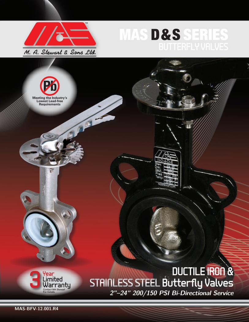
A N D V A L V E S F I T T I N G S
MAS-BFV-12.001.R4
DUCTILE IRON & STAINLESS STEEL Butterfly Valves
2”–24” 200/150 PSI Bi-Directional Service
MAS D & S SERIES BUTTERFLY VALVES
3 YearLimitedWarrantyContact MA Stewart For Details
2
2" Valve
bodies available
with 11/2" Class 1
50
wafer-style fla
nge
D Series
sizes available
wafer 11/2" — 48"*
LUg 2" — 48"*
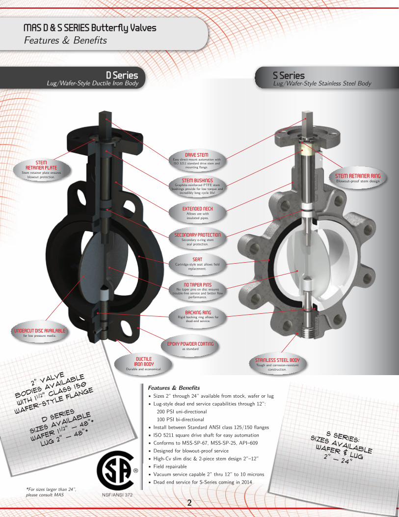
Features & Benefits• Sizes 2” through 24” available from stock, wafer or lug• Lug-style dead end service capabilities through 12”:
200 PSI uni-directional 100 PSI bi-directional
• Install between Standard ANSI class 125/150 flanges• ISO 5211 square drive shaft for easy automation• Conforms to MSS-SP-67, MSS-SP-25, API–609• Designed for blowout-proof service• High-Cv slim disc & 2-piece stem design 2”–12”• Field repairable• Vacuum service capable 2” thru 12” to 10 microns• Dead end service for S-Series coming in 2014
SEATCartridge-style seat allows field
replacement.
NO TAPER PINSNo taper pins on disc ensures
trouble-free service and better flow performance.
BACKING RINGRigid backing ring allows for
dead-end service.
STEM BUSHINGSGraphite-reinforced PTFE stem
bushings provide for low torque and incredibly long cycle life!
EXTENDED NECKAllows use with insulated pipes.
SECONDARY PROTECTIONSecondary o-ring stem
seal protection.
DRIVE STEMEasy direct-mount automation with ISO 5211 standard drive stem and
mounting flange.
STEM RETAINER RINGBlowout-proof stem design
STEM RETAINER PLATE
Stem retainer plate ensures blowout protection.
STAINLESS STEEL BODYTough and corrosion-resistant
construction.
UNDERCUT DISC AVAILABLEfor low pressure media.
DUCTILE IRON BODY
Durable and economical.
MAS D & S SERIES Butterfly ValvesFeatures & Benefits
D SeriesLug/Wafer-Style Ductile Iron Body
S SeriesLug/Wafer-Style Stainless Steel Body
S SERIES:SIZES AVAILABLEWafer & Lug 2" — 24"
*For sizes larger than 24”, please consult MAS
EPOXY POWDER COATINGas standard
3 A N D V A L V E S F I T T I N G S
www.mastewart.com
S SeriesLug/Wafer-Style Stainless Steel Body
oPTIONS• Standard handle with 10-position throttle plate• optional handle with INFINITE Lever PLATE (ILP)• mANUAL GEAR OPERATOR• aCTUAted: Pneumatic or Electric
Contact MAS for
actuation details
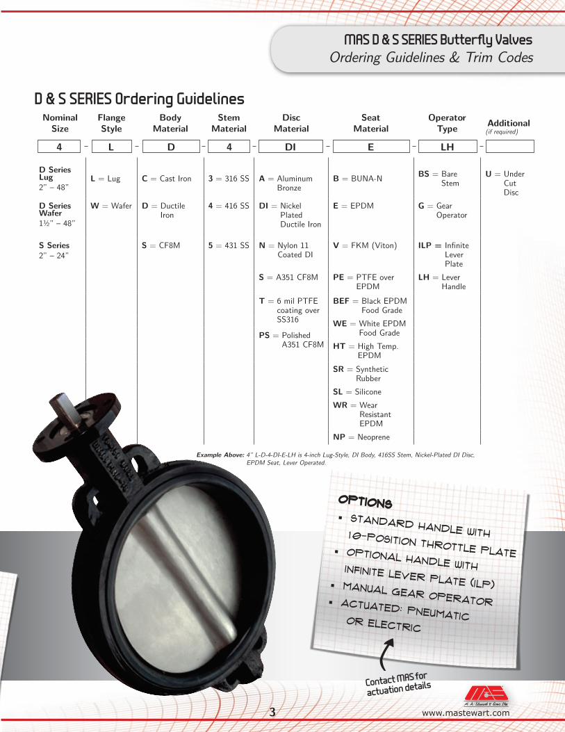
D & S SERIES Ordering Guidelines
MAS D & S SERIES Butterfly ValvesOrdering Guidelines & Trim Codes
NominalSize
FlangeStyle
Body Material
Stem Material
Disc Material
Seat Material
OperatorType Additional
D Series Lug 2” – 48”
L = Lug C = Cast Iron 3 = 316 SS A = Aluminum Bronze
B = BUNA-N BS = Bare Stem
U = Under Cut Disc
D Series Wafer 1½” – 48”
W = Wafer D = Ductile Iron
4 = 416 SS DI = Nickel Plated Ductile Iron
E = EPDM G = Gear Operator
S Series 2” – 24”
S = CF8M 5 = 431 SS N = Nylon 11 Coated DI
V = FKM (Viton) ILP = Infinite Lever Plate
S = A351 CF8M PE = PTFE over EPDM
LH = Lever Handle
T = 6 mil PTFE coating over SS316
BEF = Black EPDM Food Grade
WE = White EPDM Food GradePS = Polished
A351 CF8M HT = High Temp. EPDM
SR = Synthetic Rubber
SL = SiliconeWR = Wear
Resistant EPDM
NP = Neoprene
(if required)
4 L D 4 DI E LH
Example Above: 4” L-D-4-DI-E-LH is 4-inch Lug-Style, DI Body, 416SS Stem, Nickel-Plated DI Disc, EPDM Seat, Lever Operated.

4
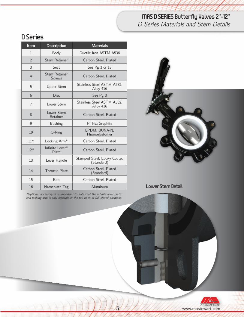
MAS D SERIES Butterfly Valves 2”-12”D Series Exploded View
8
16
1
14
15
2
12
4
5
13
11
9
9
6
7
9
10
9
10
3
5 A N D V A L V E S F I T T I N G S
www.mastewart.com
MAS D SERIES Butterfly Valves 2”-12”D Series Materials and Stem Details
Lower Stem Detail
Item Description Materials
1 Body Ductile Iron ASTM A536
2 Stem Retainer Carbon Steel, Plated
3 Seat See Pg 3 or 18
4 Stem Retainer Screws Carbon Steel, Plated
5 Upper Stem Stainless Steel ASTM A582, Alloy 416
6 Disc See Pg 3
7 Lower Stem Stainless Steel ASTM A582, Alloy 416
8 Lower Stem Retainer Carbon Steel, Plated
9 Bushing PTFE/Graphite
10 O-Ring EPDM, BUNA-N, Fluoroelastomer
11* Locking Arm* Carbon Steel, Plated
12* Infinite Lever* Plate Carbon Steel, Plated
13 Lever Handle Stamped Steel, Epoxy Coated (Standard)
14 Throttle Plate Carbon Steel, Plated(Standard)
15 Bolt Carbon Steel, Plated
16 Nameplate Tag Aluminum
D Series
*Optional accessory. It is important to note that the infinite lever plate and locking arm is only lockable in the full open or full closed positions.
6www.mastewart.com A N D V A L V E S F I T T I N G S
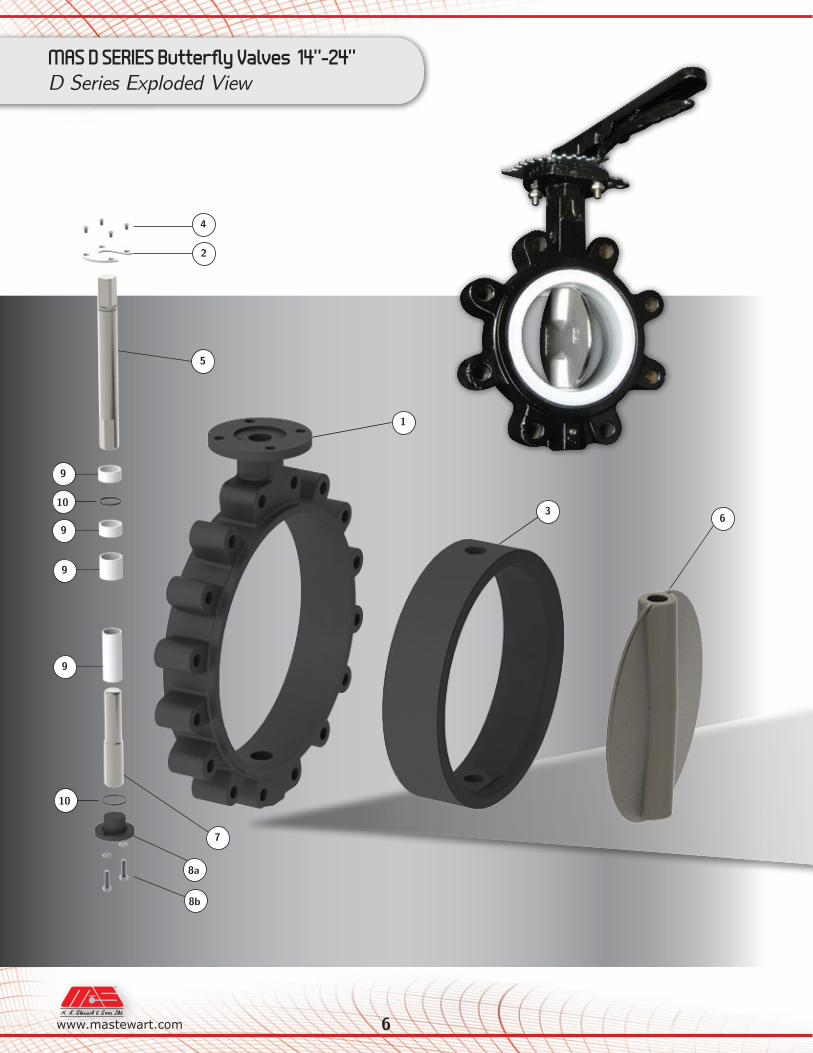
MAS D SERIES Butterfly Valves 14”-24”D Series Exploded View
2
1
3
4
5
6
7
8a
8b
9
9
9
9
10
10
7 A N D V A L V E S F I T T I N G S
www.mastewart.com
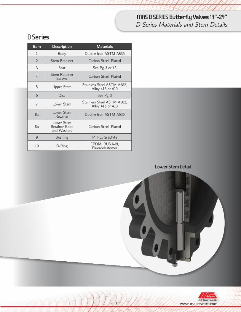
MAS D SERIES Butterfly Valves 14”-24”D Series Materials and Stem Details
Lower Stem Detail
Item Description Materials
1 Body Ductile Iron ASTM A536
2 Stem Retainer Carbon Steel, Plated
3 Seat See Pg 3 or 18
4 Stem Retainer Screws Carbon Steel, Plated
5 Upper Stem Stainless Steel ASTM A582, Alloy 416 or 410
6 Disc See Pg 3
7 Lower Stem Stainless Steel ASTM A582, Alloy 416 or 410
8a Lower Stem Retainer Ductile Iron ASTM A536
8bLower Stem
Retainer Bolts and Washers
Carbon Steel, Plated
9 Bushing PTFE/Graphite
10 O-Ring EPDM, BUNA-N, Fluoroelastomer
D Series
8
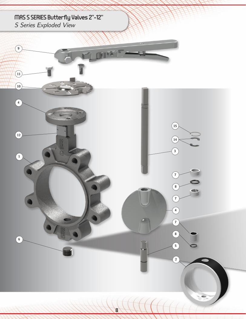
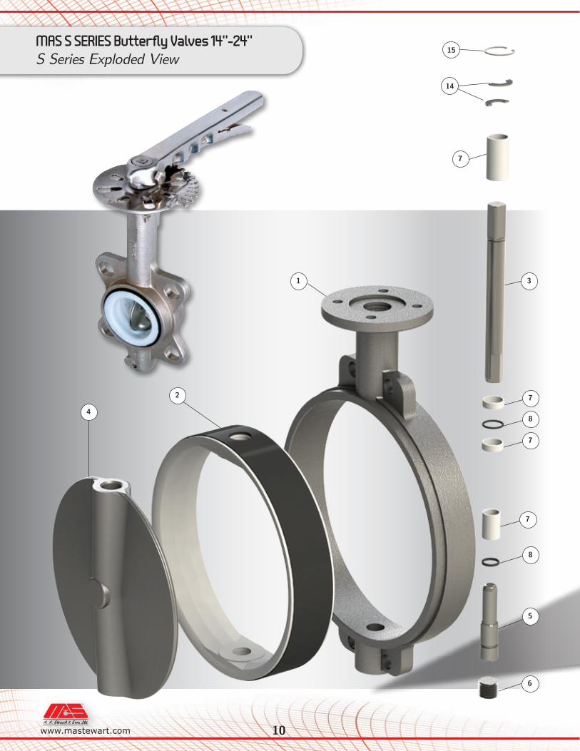
MAS S SERIES Butterfly Valves 2”-12”S Series Exploded View
2
7
7
6
8
3
10
11
12
1
9
4
8
5
7
15
14
4
9 A N D V A L V E S F I T T I N G S
www.mastewart.com
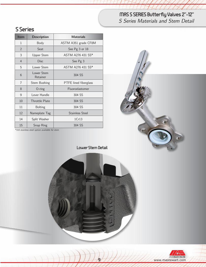
Item Description Materials
1 Body ASTM A351 grade CF8M
2 Seat See Pg 3 or 18
3 Upper Stem ASTM A276 431 SS*
4 Disc See Pg 3
5 Lower Stem ASTM A276 431 SS*
6 Lower Stem Retainer 304 SS
7 Stem Bushing PTFE lined fiberglass
8 O-ring Fluoroelastomer
9 Lever Handle 304 SS
10 Throttle Plate 304 SS
11 Bolting 304 SS
12 Nameplate Tag Stainless Steel
14 Split Washer 1Cr13
15 Snap Ring 304 SS*316 stainless steel option available for stem
S Series
MAS S SERIES Butterfly Valves 2”-12”S Series Materials and Stem Detail
Lower Stem Detail
10www.mastewart.com A N D V A L V E S F I T T I N G S
MAS S SERIES Butterfly Valves 14”-24”S Series Exploded View
1
2
3
4
5
6
7
7
7
7
8
8
14
15
11 A N D V A L V E S F I T T I N G S
www.mastewart.com
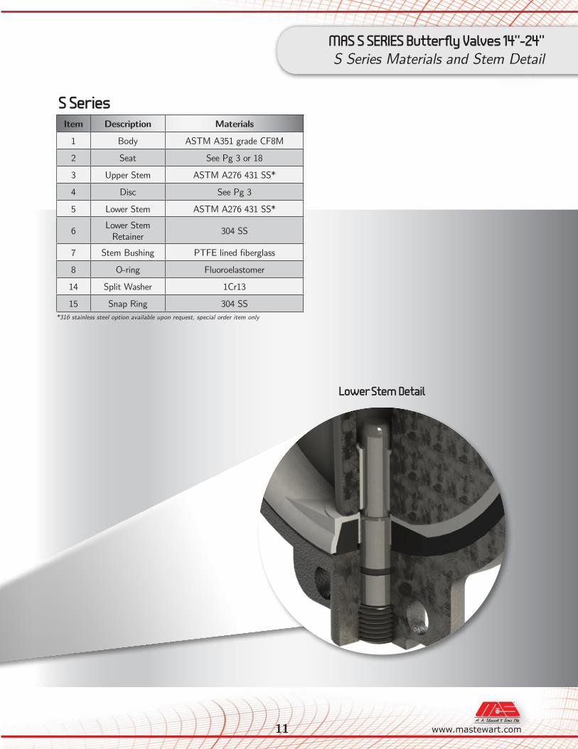
MAS S SERIES Butterfly Valves 14”-24”S Series Materials and Stem Detail
Lower Stem Detail
Item Description Materials
1 Body ASTM A351 grade CF8M
2 Seat See Pg 3 or 18
3 Upper Stem ASTM A276 431 SS*
4 Disc See Pg 3
5 Lower Stem ASTM A276 431 SS*
6 Lower Stem Retainer 304 SS
7 Stem Bushing PTFE lined fiberglass
8 O-ring Fluoroelastomer
14 Split Washer 1Cr13
15 Snap Ring 304 SS*316 stainless steel option available upon request, special order item only
S Series
12
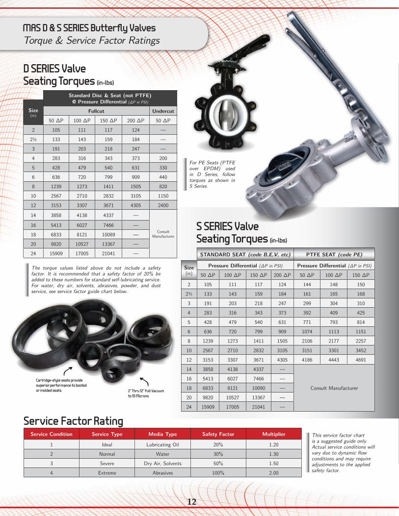
Service Condition Service Type Media Type Safety Factor Multiplier
1 Ideal Lubricating Oil 20% 1.20
2 Normal Water 30% 1.30
3 Severe Dry Air, Solvents 50% 1.50
4 Extreme Abrasives 100% 2.00
Service Factor Rating
Standard Disc & Seat (not PTFE)@ Pressure Differential (∆P in PSI)
Size (in)
Fullcut Undercut
50 ∆P 100 ∆P 150 ∆P 200 ∆P 50 ∆P
2 105 111 117 124 —
2½ 133 143 159 184 —
3 191 203 218 247 —
4 283 316 343 373 200
5 428 479 540 631 330
6 636 720 799 909 440
8 1239 1273 1411 1505 820
10 2567 2710 2832 3105 1150
12 3153 3307 3671 4305 2400
14 3858 4138 4337 —
ConsultManufacturer
16 5413 6027 7466 —
18 6833 8121 10089 —
20 9820 10527 13367 —
24 15909 17005 21041 —
D SERIES Valve Seating Torques (in-lbs)
The torque values listed above do not include a safety factor. It is recommended that a safety factor of 20% be added to these numbers for standard self-lubricating service. For water, dry air, solvents, abrasives, powder, and dust service, see service factor guide chart below.
Cartridge-style seats provide superior performance to booted or molded seats. 2” Thru 12” Full Vacuum
to 10 Microns
STANDARD SEAT (code B,E,V, etc) PTFE SEAT (code PE)
Size (in)
Pressure Differential (∆P in PSI) Pressure Differential (∆P in PSI)
50 ∆P 100 ∆P 150 ∆P 200 ∆P 50 ∆P 100 ∆P 150 ∆P
2 105 111 117 124 144 148 150
2½ 133 143 159 184 161 165 168
3 191 203 218 247 299 304 310
4 283 316 343 373 392 409 425
5 428 479 540 631 771 793 814
6 636 720 799 909 1074 1113 1151
8 1239 1273 1411 1505 2106 2177 2257
10 2567 2710 2832 3105 3151 3301 3452
12 3153 3307 3671 4305 4186 4443 4691
14 3858 4138 4337 —
Consult Manufacturer
16 5413 6027 7466 —
18 6833 8121 10090 —
20 9820 10527 13367 —
24 15909 17005 21041 —
S SERIES Valve Seating Torques (in-lbs)
This service factor chart is a suggested guide only. Actual service conditions will vary due to dynamic flow conditions and may require adjustments to the applied safety factor.
MAS D & S SERIES Butterfly ValvesTorque & Service Factor Ratings
For PE Seats (PTFE over EPDM) used in D Series, follow torques as shown in S Series.
13 A N D V A L V E S F I T T I N G S
www.mastewart.com
MAS D & S SERIES Butterfly ValvesCV Values & Testing Specs
Size (in)
Disc Position
90° 80° 70° 60° 50° 40° 30° 20° 10°
1½ 99 76 59 41 32 16 7 1.8 0.1
2 132 120 86 58 42 22 11 2 0.1
2½ 256 202 142 98 65 37 20 4 0.2
3 505 392 198 125 86 38 21 8 0.3
4 936 702 401 232 140 77 35 14 0.4
5 1109 922 625 392 232 132 62 29 0.9
6 2531 2009 1105 611 372 203 96 42 2.1
8 4812 3555 1901 1211 726 401 191 65 3.2
10 7498 6183 3740 2065 1232 695 321 151 3.9
12 9928 8805 5905 3178 1909 1065 495 234 5
14 12915 10854 7220 4560 2771 1554 712 338 5.8
16 16626 14961 9909 6289 3780 2133 980 460 8
18 23705 19743 13178 8325 5029 2822 1301 613 10
20 27915 25396 16928 10698 6468 3623 1678 790 12
24 43212 39206 26128 16550 9807 5567 2521 860 21
D SERIES & S SERIES Cv Values Valve Sizing Coefficients (US-GPM/∆P)
The valve sizing coefficient is referred to as "Cv" and is the rate of water flow in gallons per minute (GPM) through a given opening at a pressure drop (∆P) of 1 PSI at standard room temperature. The recommended angle of opening for valve sizing is between 50° and 70° open.
Standard 10-Position
Throttle Plate Shown
D SERIES & S SERIES Testing Specifications
D & S SERIES
Nominal Size 2”–12”(EPDM)
14”–24”(EPDM)
2"–12" (PTFE)
Nominal Pressure 200 PSI* 150 PSI 150 PSI
Body Test Pressure 300 PSI 225 PSI 225 PSI
Sealing Test Pressure 220 PSI 165 PSI 165 PSI
*PTFE seats are rated to 150 PSI
14
ØD1
n-Øh
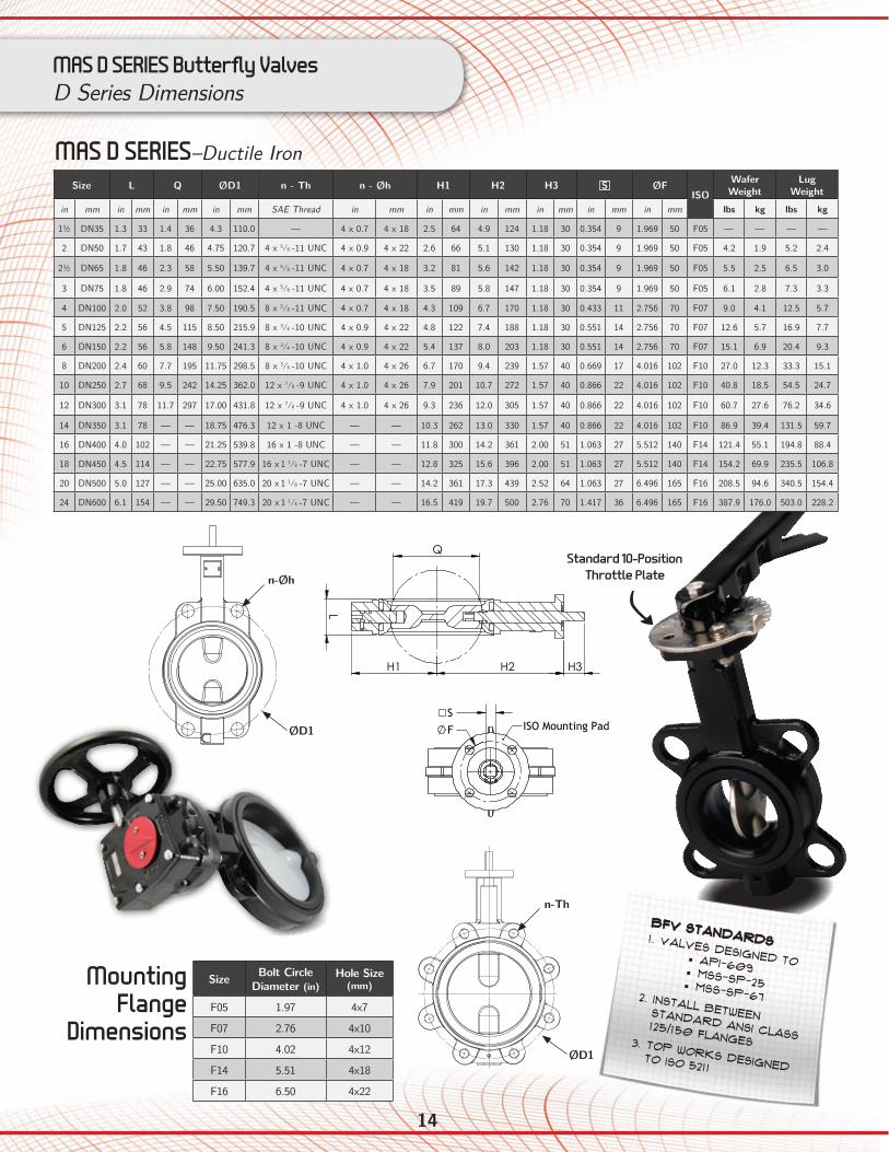
MAS D SERIES Butterfly ValvesD Series Dimensions
Size Bolt Circle Diameter (in)
Hole Size (mm)
F05 1.97 4x7
F07 2.76 4x10
F10 4.02 4x12
F14 5.51 4x18
F16 6.50 4x22
Mounting Flange
Dimensions
AA
Top flangeas per ISO
5211
n-h
H3 H2 H1
L Q
S
F
SECTIO
N A
-A
Standard
s: -V
alves designed
to API-609, M
SS-SP-67, SM-SP-25
-Install between stand
ard A
NSI C
lass 125/150 Flanges
050 Series Wafer
Butterfly Valves
050 Series BFV
2/21/2011
WEIG
HT:
8.5x11"
SHEET 1 OF 1
SCA
LE:1:4
DW
G N
O.
TITLE:
REVISION
: 2D
O N
OT SC
ALE D
RAW
ING
MA
TERIAL:
DA
TESIG
NA
TUREN
AM
E
DEBUR A
ND
BREA
K SHARP
EDG
ES
FINISH:
UNLESS O
THERWISE SPEC
IFIED:
DIM
ENSIO
NS A
RE IN IN
CHES
SURFAC
E FINISH:
TOLERA
NC
ES: LIN
EAR:
AN
GULA
R:
Q.A
MFG
APPV
'D
CHK'D
DRA
WN
REV1
DESC
RIPTION
DA
TE
BW8/17/2011
CO
RRECTED
SHAFT W
IDTH
1½" L D
IMEN
SION
9/13/20122
Standard 10-Position Throttle Plate
MAS D SERIES–Ductile Iron
BFV Standards1. Valves designed to • API-609 • MSS-SP-25 • MSS-SP-672. Install between standard ANSI Class
125/150 flanges3. Top works designed to ISO 5211
D SERIES Handle
Dimensions
n-M
D
L
H1
H2
H3
Q
S F
H2
H1
H3
n-M
D
A
A
S
F
L
Q
SECTION A-A
H3
h
H2
H1
D
A
A
F
S ISO Mounting Pad
SECTION A-A
Standards: -Valves designed to API-609, MSS-SP-67, MSS-SP-25 -Install between standard ANSI Class 125/150 Flanges -Top works designed to ISO 5211
650 Series LugButterfly Valves
650_WAFER_2_THRU_12
11/7/2012
WEIGHT:
8.5x11"
SHEET 1 OF 1SCALE:1:3
DWG NO.
TITLE:
REVISION: 1 DO NOT SCALE DRAWING
MATERIAL:
DATESIGNATURENAME
DEBUR AND BREAK SHARP EDGES
FINISH:UNLESS OTHERWISE SPECIFIED:DIMENSIONS ARE IN INCHESSURFACE FINISH:TOLERANCES: LINEAR: ANGULAR:
Q.A
MFG
APPV'D
CHK'D
DRAWN
REV
DESCRIPTIONDATE
BW
ØD1
n-Th
Size L Q ØD1 n - Th n - Øh H1 H2 H3 S ØFISO
Wafer Weight
Lug Weight
in mm in mm in mm in mm SAE Thread in mm in mm in mm in mm in mm in mm lbs kg lbs kg
1½ DN35 1.3 33 1.4 36 4.3 110.0 –– 4 x 0.7 4 x 18 2.5 64 4.9 124 1.18 30 0.354 9 1.969 50 F05 — — — —
2 DN50 1.7 43 1.8 46 4.75 120.7 4 x 5⁄8 -11 UNC 4 x 0.9 4 x 22 2.6 66 5.1 130 1.18 30 0.354 9 1.969 50 F05 4.2 1.9 5.2 2.4
2½ DN65 1.8 46 2.3 58 5.50 139.7 4 x 5⁄8 -11 UNC 4 x 0.7 4 x 18 3.2 81 5.6 142 1.18 30 0.354 9 1.969 50 F05 5.5 2.5 6.5 3.0
3 DN75 1.8 46 2.9 74 6.00 152.4 4 x 5⁄8 -11 UNC 4 x 0.7 4 x 18 3.5 89 5.8 147 1.18 30 0.354 9 1.969 50 F05 6.1 2.8 7.3 3.3
4 DN100 2.0 52 3.8 98 7.50 190.5 8 x 5⁄8 -11 UNC 4 x 0.7 4 x 18 4.3 109 6.7 170 1.18 30 0.433 11 2.756 70 F07 9.0 4.1 12.5 5.7
5 DN125 2.2 56 4.5 115 8.50 215.9 8 x 3⁄4 -10 UNC 4 x 0.9 4 x 22 4.8 122 7.4 188 1.18 30 0.551 14 2.756 70 F07 12.6 5.7 16.9 7.7
6 DN150 2.2 56 5.8 148 9.50 241.3 8 x 3⁄4 -10 UNC 4 x 0.9 4 x 22 5.4 137 8.0 203 1.18 30 0.551 14 2.756 70 F07 15.1 6.9 20.4 9.3
8 DN200 2.4 60 7.7 195 11.75 298.5 8 x 3⁄4 -10 UNC 4 x 1.0 4 x 26 6.7 170 9.4 239 1.57 40 0.669 17 4.016 102 F10 27.0 12.3 33.3 15.1
10 DN250 2.7 68 9.5 242 14.25 362.0 12 x 7⁄8 -9 UNC 4 x 1.0 4 x 26 7.9 201 10.7 272 1.57 40 0.866 22 4.016 102 F10 40.8 18.5 54.5 24.7
12 DN300 3.1 78 11.7 297 17.00 431.8 12 x 7⁄8 -9 UNC 4 x 1.0 4 x 26 9.3 236 12.0 305 1.57 40 0.866 22 4.016 102 F10 60.7 27.6 76.2 34.6
14 DN350 3.1 78 — — 18.75 476.3 12 x 1 -8 UNC — — 10.3 262 13.0 330 1.57 40 0.866 22 4.016 102 F10 86.9 39.4 131.5 59.7
16 DN400 4.0 102 — — 21.25 539.8 16 x 1 -8 UNC — — 11.8 300 14.2 361 2.00 51 1.063 27 5.512 140 F14 121.4 55.1 194.8 88.4
18 DN450 4.5 114 — — 22.75 577.9 16 x 1 1⁄8 -7 UNC — — 12.8 325 15.6 396 2.00 51 1.063 27 5.512 140 F14 154.2 69.9 235.5 106.8
20 DN500 5.0 127 — — 25.00 635.0 20 x 1 1⁄8 -7 UNC — — 14.2 361 17.3 439 2.52 64 1.063 27 6.496 165 F16 208.5 94.6 340.5 154.4
24 DN600 6.1 154 — — 29.50 749.3 20 x 1 1⁄4 -7 UNC — — 16.5 419 19.7 500 2.76 70 1.417 36 6.496 165 F16 387.9 176.0 503.0 228.2
15 A N D V A L V E S F I T T I N G S
www.mastewart.com
MAS D SERIES Butterfly ValvesGear and Handle Options
E
A
B F
D
C
DO NOT SCALE DRAWING4in BFV Handle
SHEET 1 OF 1
BW
UNLESS OTHERWISE SPECIFIED:
SCALE: 1:2 WEIGHT:
DWG. NO.
ASIZE
TITLE:
NAME DATE
REVISIONS:
CHECKED
DRAWN
FINISH
MATERIAL
INTERPRET GEOMETRICTOLERANCING PER:
DIMENSIONS ARE IN INCHESTOLERANCES:FRACTIONAL 1/32ANGULAR: MACH BEND TWO PLACE DECIMAL 0.015THREE PLACE DECIMAL .005
PROPRIETARY AND CONFIDENTIAL
THE INFORMATION CONTAINED IN THISDRAWING IS THE SOLE PROPERTY OFMAX-AIR TECHNOLOGY, INC. ANY REPRODUCTION IN PART OR AS A WHOLEWITHOUT THE WRITTEN PERMISSION OFMAX-AIR TECHNOLOGY, INC. IS PROHIBITED.
5 4 3 2 1
751 Hoff RoadO'Fallon, MO 63366
Phone: 888-842-9998Fax: 636-272-4937
max-airtechnology.com
REV
COMMENTS:
C
M
Y
CM
MY
CY
CMY
K
4in BFV Handle.PDF 1 7/30/12 11:44 AM
Handle CodeValve Handle Assembly A B C D E F Weight
in mm in mm in mm in mm in mm in mm lbs kgin mm
HANDLE 220-01 2"–3" DN50–75 0.88 22.4 0.354 9.0 1.25 31.8 8.7 220 9 229 1.0 25.4 1.0 0.5
HANDLE 260-01 4" DN100 1.00 25.4 0.433 11.0 1.38 35.1 10.2 260 12 305 1.1 27.9 2.0 0.9
HANDLE 260-02 5"–6" DN125–150 1.00 25.4 0.433 14.0 1.38 35.1 10.2 260 12 305 1.1 27.9 2.0 0.9
HANDLE 360-01 8"* DN200* 1.25 31.8 0.669 17.0 1.75 44.5 14.2 360 14 356 1.4 35.6 3.0 1.4
HANDLE 360-02 10"–12"* DN250–300* 1.25 31.8 0.669 22.0 1.75 44.5 14.2 360 14 356 1.4 35.6 3.0 1.4
D SERIES Handle
Dimensions
A
H
B
C
M
Y
CM
MY
CY
CMY
K
051 4in BFV_GO-01-ISO.PDF 1 7/19/12 4:13 PM
The standard 10-position throttle plate has grooves that allow the handle to snap in place for repeatability and to prevent unintentional movement of the disc.
For even more control, Infinite Lever Plates (ILP) and arms are available, which allow the valve to be fixed in place with a bolt at any position. It is important to note that the ILP plates and locking arms can be padlocked in the full open and full closed positions only, to prevent tampering or accidental operation.
Infinite Lever PlateLocking arm
Over-Travel on Infinite 2-Position Lock Option Allows Disc to Wipe Seat
Gear OperatorPadlocked Closed
ILP Shown
Padlocked in
the Fully
Closed Position
Valve Size Gear Operator
A B ØH Weight Output Torquein mm in mm in mm in mm lbs kg in-lbs Nm
1.5–3 DN50–75 MA-GO-01A-ISO 1.7 43 3.2 81 6 152 2.8 1.3 1330 1504 DN100 MA-GO-01B-ISO 1.7 43 3.2 81 6 152 2.8 1.3 1330 150
5–6 DN125–150 MAS-GO-02-ISO 2.5 64 3.6 91 6 152 5.6 2.5 2200 2508 DN200 MAS-GO-03A-ISO 2.4 61 4.7 119 10 254 11.5 5.2 4425 50010 DN250 MAS-GO-03B-ISO 2.4 61 4.7 119 10 254 11.5 5.2 4425 500
12–14 DN300–350 MAS-GO-04-ISO 2.6 66 6.5 165 12 305 22.2 10.1 8850 100016–18 DN400–450 MAS-GO-05-ISO 3.5 89 7.9 201 16 406 40.8 18.5 15900 1800
20 DN500 MAS-GO-06-ISO 5.0 127 10.1 257 16 406 78.1 35.4 30090 340024 DN600 MAS-GO-07-ISO 6.1 155 12.4 315 16 406 101 45.8 39825 4500
Gear Operator Dimensions
*Recommended operation with a gear operator or an actuator for sizes 8”–12”
ILP Shown
Bolted in an
Intermediate
Position
Valve Size Infinite Lever Plate
Infinite Lever Armin mm
2–2½ DN50–65 01 01
3 DN75 01 02
4 DN100 02 03
5–6 DN125–150 02 04
8* DN200* 03 05
10–12* DN250–300* 03 06
Infinite Lever Details
A
H
B
C
M
Y
CM
MY
CY
CMY
K
051 4in BFV_GO-01-ISO.PDF 1 7/19/12 4:13 PM
16
Size L Q ØD1 n - Th n - Øh H1 H2 H3 S ØFISO
Wafer Weight
Lug Weight
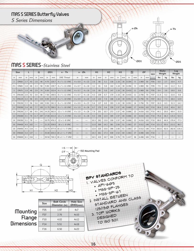
in mm in mm in mm in mm SAE Thread in mm in mm in mm in mm in mm in mm lbs kg lbs kg
2 DN50 1.7 43 1.8 46 4.75 120.7 4 x 5⁄8 -11 UNC 4 x 0.9 4 x 22 2.6 66 5.1 130 1.18 30 0.354 9 1.969 50 F05 6.0 2.7 10.4 4.7
2½ DN65 1.8 46 2.3 58 5.50 139.7 4 x 5⁄8 -11 UNC 4 x 0.7 4 x 18 3.2 81 5.6 142 1.18 30 0.354 9 1.969 50 F05 7.5 3.4 11.2 5.1
3 DN75 1.8 46 2.9 74 6.00 152.4 4 x 5⁄8 -11 UNC 4 x 0.7 4 x 18 3.5 89 5.8 147 1.18 30 0.433 11 1.969 50 F05 8.4 3.8 19.0 8.6
4 DN100 2.0 52 3.8 98 7.50 190.5 8 x 5⁄8 -11 UNC 4 x 0.7 4 x 18 4.3 109 6.7 170 1.18 30 0.433 11 2.756 70 F07 11.5 5.2 21.6 9.8
5 DN125 2.2 56 4.5 115 8.50 215.9 8 x 3⁄4 -10 UNC 4 x 0.9 4 x 22 4.8 122 7.4 188 1.18 30 0.551 14 2.756 70 F07 16.1 7.3 28.4 12.9
6 DN150 2.2 56 5.8 148 9.50 241.3 8 x 3⁄4 -10 UNC 4 x 0.9 4 x 22 5.4 137 8.0 203 1.18 30 0.551 14 2.756 70 F07 18.3 8.3 31.3 14.2
8 DN200 2.4 60 7.7 195 11.75 298.5 8 x 3⁄4 -10 UNC 4 x 1.0 4 x 26 6.7 170 9.4 239 1.57 40 0.669 17 4.016 102 F10 30.4 13.8 45.6 20.7
10 DN250 2.7 68 9.5 242 14.25 362.0 12 x 7⁄8 -9 UNC 4 x 1.0 4 x 26 7.9 201 10.7 272 1.57 40 0.866 22 4.016 102 F10 44.1 20.0 69.4 31.5
12 DN300 3.1 78 11.7 297 17.00 431.8 12 x 7⁄8 -9 UNC 4 x 1.0 4 x 26 9.3 236 12.0 305 1.57 40 0.866 22 4.016 102 F10 75.4 34.2 115.3 52.3
14 DN350 3.1 78 — — 18.75 476.3 12 x 1 -8 UNC — — 10.3 262 13.0 330 1.57 40 0.866 22 4.016 102 F10 99.0 44.9 170.4 77.3
16 DN400 4.0 102 — — 21.25 539.8 16 x 1 -8 UNC — — 11.8 300 14.2 361 2.00 51 1.063 27 5.512 140 F14 121.3 55.0 213.2 96.7
18 DN450 4.5 114 — — 22.75 577.9 16 x 1 1⁄8 -7 UNC — — 12.8 325 15.6 396 2.00 51 1.063 27 5.512 140 F14 202.8 92.0 262.8 119.2
20 DN500 5.0 127 — — 25.00 635.0 20 x 1 1⁄8 -7 UNC — — 14.2 361 17.3 439 2.52 64 1.063 27 6.496 165 F16 — — — —
24 DN600 6.1 154 — — 29.50 749.3 20 x 1 1⁄4 -7 UNC — — 16.5 419 19.7 500 2.76 70 1.417 36 6.496 165 F16 — — — —
MAS S SERIES Butterfly ValvesS Series Dimensions
BFV Standards
1. Valves conform to
• API-609
• MSS-SP-25
• MSS-SP-67
2. Install between
standard ANSI Class
125/150 flanges
3. Top works
designed
to ISO 5211
Size Bolt Circle Diameter (in)
Hole Size ØHD(mm)
F05 1.97 4x7
F07 2.76 4x10
F10 4.02 4x12
F14 5.51 4x18
F16 6.50 4x22
Mounting Flange
Dimensions
MAS S SERIES–Stainless SteelØD1
n-Øh
ØD1
n-Th
AA
Top flangeas per ISO
5211
n-h
H3 H2 H1
L
Q
S
F
SECTIO
N A
-A
Standard
s: -V
alves designed
to API-609, M
SS-SP-67, SM-SP-25
-Install between stand
ard A
NSI C
lass 125/150 Flanges
050 Series Wafer
Butterfly Valves
050 Series BFV
2/21/2011
WEIG
HT:
8.5x11"
SHEET 1 OF 1
SCA
LE:1:4
DW
G N
O.
TITLE:
REVISION
: 2D
O N
OT SC
ALE D
RAW
ING
MA
TERIAL:
DA
TESIG
NA
TUREN
AM
E
DEBUR A
ND
BREA
K SHARP
EDG
ES
FINISH:
UNLESS O
THERWISE SPEC
IFIED:
DIM
ENSIO
NS A
RE IN IN
CHES
SURFAC
E FINISH:
TOLERA
NC
ES: LIN
EAR:
AN
GULA
R:
Q.A
MFG
APPV
'D
CHK'D
DRA
WN
REV1
DESC
RIPTION
DA
TE
BW8/17/2011
CO
RRECTED
SHAFT W
IDTH
1½" L D
IMEN
SION
9/13/20122
n-M
D
L
H1
H2
H3
Q
S F
H2
H1
H3
n-M
D
A
A
S
F
L
Q
SECTION A-A
H3
h
H2
H1
D
A
A
F
S ISO Mounting Pad
SECTION A-A
Standards: -Valves designed to API-609, MSS-SP-67, MSS-SP-25 -Install between standard ANSI Class 125/150 Flanges -Top works designed to ISO 5211
650 Series LugButterfly Valves
650_WAFER_2_THRU_12
11/7/2012
WEIGHT:
8.5x11"
SHEET 1 OF 1SCALE:1:3
DWG NO.
TITLE:
REVISION: 1 DO NOT SCALE DRAWING
MATERIAL:
DATESIGNATURENAME
DEBUR AND BREAK SHARP EDGES
FINISH:UNLESS OTHERWISE SPECIFIED:DIMENSIONS ARE IN INCHESSURFACE FINISH:TOLERANCES: LINEAR: ANGULAR:
Q.A
MFG
APPV'D
CHK'D
DRAWN
REV
DESCRIPTIONDATE
BW
17 A N D V A L V E S F I T T I N G S
www.mastewart.com
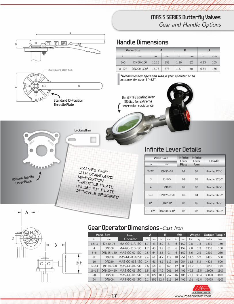
MAS S SERIES Butterfly ValvesGear and Handle Options
Valve Size Gear Operator
A B ØH Weight Output Torquein mm in mm in mm in mm lbs kg in-lbs Nm
1.5–3 DN50–75 MA-GO-01A-ISO 1.7 43 3.2 81 6 152 2.8 1.3 1330 1504 DN100 MA-GO-01B-ISO 1.7 43 3.2 81 6 152 2.8 1.3 1330 150
5–6 DN125–150 MAS-GO-02-ISO 2.5 64 3.6 91 6 152 5.6 2.5 2200 2508 DN200 MAS-GO-03A-ISO 2.4 61 4.7 119 10 254 11.5 5.2 4425 50010 DN250 MAS-GO-03B-ISO 2.4 61 4.7 119 10 254 11.5 5.2 4425 500
12–14 DN300–350 MAS-GO-04-ISO 2.6 66 6.5 165 12 305 22.2 10.1 8850 100016–18 DN400–450 MAS-GO-05-ISO 3.5 89 7.9 201 16 406 40.8 18.5 15900 1800
20 DN500 MAS-GO-06-ISO 5.0 127 10.1 257 16 406 78.1 35.4 30090 340024 DN600 MAS-GO-07-ISO 6.1 155 12.4 315 16 406 101 45.8 39825 4500
Gear Operator Dimensions–Cast Iron
Valves ship with standard 10-position throttle plate unless ILP Plate option is specified.
Valve Size A B D
in mm in mm in mm in mm
2–6 DN50–150 10.16 258 1.26 32 4.13 105
8–12* DN200–300* 14.76 373 1.57 40 6.54 166
Handle Dimensions
*Recommended operation with a gear operator or an actuator for sizes 8”–12”
Valve Size Infinite Lever Plate
Infinite Lever Arm
Handlein mm
2–2½ DN50–65 01 01 Handle 220-1
3 DN75 01 02 Handle 220-2
4 DN100 02 03 Handle 260-1
5–6 DN125–150 02 04 Handle 260-2
8* DN200* 03 05 Handle 360-1
10–12* DN250–300* 03 06 Handle 360-2
Infinite Lever Details
A
H
B
C
M
Y
CM
MY
CY
CMY
K
051 4in BFV_GO-01-ISO.PDF 1 7/19/12 4:13 PM
A
H
B
C
M
Y
CM
MY
CY
CMY
K
051 4in BFV_GO-01-ISO.PDF 1 7/19/12 4:13 PM
6 mil PTFE coating over SS disc for extreme
corrosion resistance Standard 10-Position Throttle Plate
Optional Infinite
Lever Plate
Locking Arm
18
MAS D & S SERIES Butterfly ValvesSeat Material Guide
Seat Material(Backing Material) Code General Application Temperature Range
at Full Rated Pressure Not Recommended For
NitrileBuna-N (NBR)
(Phenolic Backing)
Black BUNA (Code B)
Hydrocarbons with less than 40% of aromatics, Natural Gas, Air, H2O, Sea Water, Brine, Alcohols, Glycols
10°F to 180°F
Solvents, Benzene, Xylene
-12°C to 82°C
EPDM(Phenolic Backing)
Black EPDM (Code E)
H2O, Saturated Steam*, Air, Brine, Abrasives,
Phosphates, Esters, Ketones, Alkali, Food Compounds, Liquids and Solids, Dilute Inorganic Acids, Caustic
Soda
(*low pressure saturated steam only. Please consult MAS for
details.)
-4°F to 275°F
Hydrocarbons, Oils,Fats, Dry Air
White EPDMFood Grade (Code WEF)
-20°C to 135°CBlack EPDM Food Grade (Code BEF)
High Temperature EPDM
(Phenolic Backing)
High Temp EPDM
(Code HT)
-4°F to 302°F
-20°C to 150°C
Chlorosulfonated Synthetic Rubber
(CSM)(Phenolic Backing)
(Code SR)
Oxidizing Acids, Chromic Acid, Hydrofluoric Acid, Sulphur Based Acids,
Sodium Hypochlorite, Ozone
0°F to 275°FSteam, Ketones,
Hot Air, Nitric Acid-18°C to 135°C
Silicone(Phenolic Backing) (Code SL) Beverages, Food
-22°F to 400°FHydrocarbons,
Solvents, Steam-30°C to 204°C
Fluoroelastomer (FKM-VITON)
(Aluminum Backing)(Code V)
Hydrocarbons with high concentration of aromatics, Mineral and Halogenated Acids, Phosphoric Acid, Aliphatic and Aromatic
Ethers
0°F to 392°FSteam, Ketones, Amines,
Esters, Alkali-18°C to 200°C
Neoprene (CR)(Phenolic Backing) (Code NP) Oils, Dilute Mineral Acids,
Alkali, Fats
20°F to 200°FKetones, Concentrated Acids,
Solvents for Paint-7°C to 93°C
Wear ResistantEPDM
(Phenolic Backing)(Code WR) Abrasive Products
14°F to 250°F
Steam, Hydrocarbons, Oils
-10°C to 120°C
PTFE Over EPDM(Phenolic Backing)Rated to 150 PSI
(Code PE) Corrosive Products, Solvents
-4°F to 250°FAbrasive Products, Fluorine
Gases, Alkaline Metals-20°C to 120°C
19 A N D V A L V E S F I T T I N G S
www.mastewart.com
MAS D & S SERIES Butterfly ValvesCrossover Guide
Body Ductile Iron
Valve TypeDisc Ductile Iron-Nickel Plated Aluminum-Bronze 316 Stainless Steel
Seat EPDM BUNA EPDM BUNA EPDM BUNA
W-D-4-DI-E W-D-4-DI-B W-D-4-A-E W-D-4-A-B W-D-4-S-E W-D-4-S-B Wafer
L-D-4-DI-E L-D-4-DI-B L-D-4-A-E L-D-4-A-B L-D-4-S-E L-D-4-S-B Lug
Bray30-11010-119 30-11010-713 30-11010-120 30-11010-684 30-11010-124 30-11010-125 Wafer
31-11010-119 31-11010-713 31-11010-120 31-11010-684 31-11010-124 31-11010-125 Lug
CenterlineA2-021-05 A2-021-01 A2-061-05 A2-061-01 A2-044-05 A2-044-01 Wafer
B2-021-05 B2-021-01 B2-061-05 B2-061-01 B2-044-05 B2-044-01 Lug
DemcoNE-C111535_ NE-C111531_ NE-C111435_ NE-C111431_ NE-C112235_ NE-C112231_ Wafer
NE-C511535_ NE-C511531_ NE-C511435_ NE-C511431_ NE-C512235_ NE-C512231_ Lug
GrinnellWD-820_-3 WD-810_-3 WD-828_-3 WD-818_-3 WD-827_-4 WD-817_-4 Wafer
LD-820_-3 LD-810_-3 LD-828_-3 LD-818_-3 LD-827_-4 LD-817_-4 Lug
Jenkins_223E_J _223B_J _222E_J _222B_J _221E_J _221B_J Wafer
_233E_J _233B_J _232E_J _232B_J _231E_J _231B_J Lug
KeystoneAR1-323 AR1-285 AR1-061 AR1-064 AR1-805 AR1-723 Wafer
AR2-323 AR2-285 AR2-061 AR2-064 AR2-805 AR2-723 Lug
Kitz5112E 5112B 5122E 5122B 5141E 5141B Wafer
6112E 6112B 6122E 6122B 6141E 6141B Lug
MilwaukeeMW-232-E MW-232-B MW-233-E MW-233-B MW-234-E MW-234-B Wafer
ML-232-E ML-232-B ML-233-E ML-233-B ML-234-E ML-234-B Lug
Mueller Steam
SERIES 51 SERIES 51 87-INB6 87-INB3 87-INH6 87-INH3 Wafer
SERIES 52 SERIES 52 88-INB6 88-INB3 88-INH6 88-INH3 Lug
NIBCOWD-2010 WD-2110 WD-2000 WD-2100 WD-3022 WD-3122 Wafer
LD-2010 LD-2110 LD-2000 LD-2100 LD-3022 LD-3122 Lug
CROSSOVER GUIDE
A N D V A L V E S F I T T I N G S
ww
w.m
aste
war
t.co
m
The technical data contained herein regarding operating torque, flow capacity, pressure and temperature range, etc. have been compiled from factory testing, field service, engineering calculations, and generally available technical specifications. This information is intended to serve as general parameters for specifying and sizing the valves in this brochure for standard service. For non-standard applications, or where there is any confusion or uncertainty about the technical data provided in this document, please contact your local distributor for advice pertaining to the specific application and/or perform application-specific testing to assess/confirm the suitability of these valves. The data and specifications in this brochure are correct to the best of our knowledge; however, we take no liability for inaccuracy thereof or for any damage or injury as a result of such errors or of using these valves outside of the recommended specifications, and all information herein may be subject to change without notification as deemed necessary by the factory.
R12092013
H e a d O ff i c e 12900-87th Avenue
Surrey, Brit ish Columbia
Canada V3W 3H9
mail to: P.O. 258, Surrey, BC, V3T 4W8
Phone: (604) 594-8431
Tol l Free North America: 1-800-594-8431
Fax: (604) 594-4335
O n t a r i o B r a n c h 40 Pugsley Court
Ajax, Ontario L1Z 0L8
Phone: (905) 683-7303
Fax: (905) 683-9108
A l b e r t a B r a n c h 3006 - 51 Avenue, Unit #4
Edmonton, Alberta T6P 0E1
Phone: (780) 436-9051
Fax: (780) 435-0463
Tol l Free in Alberta 1-800-232-7376
Q u e b e c B r a n c h 79H Brunswick Blvd.
Dollard-des-Ormeaux, Que. H9B 2J5
Phone: (514) 421-6311
Fax: (514) 421-6323
S a l e s O ff i c e s Calgary, Alberta
Phone: (403) 252-7262
Fax: (403) 253-8455
Winnipeg, Manitoba
Phone: (204) 837-5604
Fax: (204) 896-1992
Dartmouth, Nova Scotia
Phone: (905) 683-7303
Fax: (905) 683-9108
CAUTION
Long Beach Branch1811 E. 28th StreetSignal Hi l l , CA 90755Phone: (562) 595-1811Tol l Free: 1-888-337-7598Fax: (562) 426-6016
Bakersfield Branch5225 Gi lmore Ave.Bakersf ie ld, CA 93308-6302Phone: (661) 322-1935Tol l Free: 1-877-258-6166Fax: (661) 322-6719
Charlotte Branch803 Press ley Road, Sui te 107Char lot te, North Carol ina, 28217Phone: (704) 527-0722Tol l Free: 1-866-582-5837Fax: (704) 527-0791Tol l Free: 1-866-810-9287