Embed Size (px)
Citation preview

National Aeronautics and Space Administration Marshall Space Flight Center Digital Manufacturing
Marshall Space Flight Center Digital ManufacturingDigital ManufacturingDigital Manufacturing
Ed AEd AEd ArayaJacobs ESTSEM40 Digital Manufacturing
Ed ArayaJacobs ESTSEM40 Digital Manufacturingwww.nasa.gov
EM40 Digital Manufacturing10/7/08EM40 Digital Manufacturing10/7/08
https://ntrs.nasa.gov/search.jsp?R=20090008673 2018-09-07T03:31:16+00:00Z

Marshall Space Flight Center
♦ Established in 1960♦ Employees: 7,000
(2,600 Civil Service; 4,400 contractor)( , ; , )♦ Location: 1,841 acres on Redstone Arsenal
in Huntsville, AL♦ Buildings: 237 with 4 5M sq ft of space♦ Buildings: 237 with 4.5M sq ft of space♦ One-of-a-kind facilities: 50♦ Nearby resources:
• National Space Science & Technology Center ♦ $2 7B budget (FY07)• National Space Science & Technology Center• Cummings Research Park• Alabama A & M University • University of Alabama in Huntsville• U S Space & Rocket Center
♦ $2.7B budget (FY07)♦ Part of NASA’s nearly $1B annual
Alabama impact♦ Payroll since 1960: $6 1B• U.S. Space & Rocket Center ♦ Payroll since 1960: $6.1B♦ Engages 20,800 people in
47 states♦ Manages Michoud Assembly
2National Aeronautics and Space Administration
g yFacility near New Orleans

Marshall Space Flight Center
♦ Development of the Saturn V rocket that transported the first humans to the moon
♦ Development of the space shuttle p ppropulsion system
♦ Managing the development of Skylab, Spacelab, and International Space Station nodes.
♦ Managing projects such as the Hubble Space Telescope, the Chandra X-ray O fObservatory, and other scientific projects.
♦ Managing Ares I and Ares V of the Constellation program.
3National Aeronautics and Space Administration

Outline
1. DELMIA History at MSFC2. Constellation Program Overview3. Ares I Upper Stage4. Digital Manufacturing Implementation for Ares I US5. Problems/Challenges We’ve Faced6. Producibility/Simulation Analysis Examples
4National Aeronautics and Space Administration

DELMIA D5 Legacy
♦ DELMIA has been in use at MSFC since 1986.
Th f b ti i d♦ The use of robotics, ergonomics, and assembly has been vital for the center in project studies as well as investigations.g
♦ EM40 (Process Development)• ET – SOFI Process Development• SSME- MCC Weld Repair
SLI C t k P d ibilit• SLI- Cryotank Producibility• SRB – Mobile Robotic System for
KSC• RSRM – Waterblast Refurbishments
♦ EV10 (System Analysis)• SpaceHab RMS Reach Analysis• Nuclear Vehicle Proximity Operations• gLIMIT Snubber Interference Analysis
5National Aeronautics and Space Administration
gLIMIT Snubber Interference Analysis• Quench Module Insert Operations• ISS Proximity Operations (APMAT)

STS-107 Columbia Investigation
♦ TD53 - Video, film, trajectory data, and camera locations
♦ Task• Use existing film and video images to quantify position and velocity of the foam impact• Use existing film and video images to quantify position and velocity of the foam impact
on the Columbia wing @ T+81 seconds.
♦ Goal• Generate a trajectory which does not violate the video.
D t i i t l d d f i t• Determine point, angle, and speed of impact.
Camera 208
Camera 204
6National Aeronautics and Space Administration
Camera 212

Trajectory and Perspective Simulation
♦ Generation of 3-D virtual flight of Columbia during the first 82 seconds of the mission using imbedded trajectory data.
♦ Position virtual cameras♦ Position virtual cameras in this environment to match the coordinates of physical camera positions and viewpositions and view angle with matched focal point.
7National Aeronautics and Space Administration
Camera 212 Camera 208

Line-of-Sight Vector Generation
♦ Match DELMIA model to video image.
♦ Move virtual foam ball until it aligns with red pixels highlighted by TD53.
♦ Draw a line from camera position to foam ball to generate line-of-sight vector.
Original E212 File Video E212 Fil Vid M d ith DELMIA IOriginal E212 File Video E212 File Video Merged with DELMIA Image
DELMIA Generated Image
8National Aeronautics and Space Administration
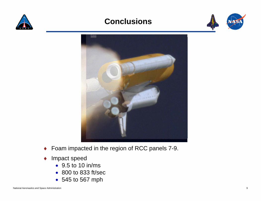
Conclusions
♦ Foam impacted in the region of RCC panels 7-9.
♦ Impact speed9 5 t 10 i /
9National Aeronautics and Space Administration
• 9.5 to 10 in/ms• 800 to 833 ft/sec• 545 to 567 mph

Outline
1. DELMIA History at MSFC2. Constellation Program Overview3. Ares I Upper Stage4. Digital Manufacturing Implementation for Ares I US5. Problems/Challenges We’ve Faced6. Producibility/Simulation Analysis Examples
10National Aeronautics and Space Administration

Vision for Space Exploration
♦The Vision for Space Exploration Program• Was announced by President Bush on January 14, 2004• It basically called for the following:y g
− Complete the ISS in 2010− Retire the Space Shuttle in 2010 after ISS completion− Replace the Space Shuttle with a new vehicle and fly it by 2014− Return man to the moon by 2020
Set the stage for a manned trip to Mars and Beyond− Set the stage for a manned trip to Mars and Beyond
♦The Vision is now referred to as the Constellation Program• Funding was not approved until 2005• It was late 2005 / early 2006 before work started to ramp upy p p
♦Ares I• The purpose of this vehicle is to lift astronauts to the ISS or to rendezvous
with the Earth Departure Stage (EDS)W i i ll f d t th C L h V hi l• Was originally referred to as the Crew Launch Vehicle
♦Ares V• This is the heavy lift vehicle which can lift satellites or other cargo to space• Will also deliver the EDS to orbit for rendezvous with the Orion capsule
11National Aeronautics and Space Administration
• Will also deliver the EDS to orbit for rendezvous with the Orion capsule• Was originally referred to as the Cargo Lift Vehicle

Vision for Space Exploration
12National Aeronautics and Space Administration

Evolutionary Space TransportationLaunch Vehicle Comparisons
Orion Crew
Altair Lunar Lander
Earth DepartureStage (EDS) (1 J-2X)
Lander
CrewLaunch Abort System
Capsule
Upper Stage(1 J-2X)
Stage (EDS) (1 J 2X)493k lb LOx/LH2
S-IVB(1 J-2 engine)240k lb LOx/LH2
305k lb LOx/LH2
5-Segment
Core Stage(5 RS-68 Engines)3.1M lb LOx/LH2
S-II(5 J-2 engines)1M lb LOx/LH2
gReusable Solid Rocket Booster (RSRB)
Two 5-SegmentRSRBs
S-IC(5 F-1 engines)3.9M lb LOx/RP
Height: 184.2 ftGross Liftoff Mass: 4.5M lb
Space Shuttle Ares IHeight: 328 ft
Gross Liftoff Mass: 2.0M lb
Ares VHeight: 362 ft
Gross Liftoff Mass: 7.3M lb
Saturn VHeight: 364 ft
Gross Liftoff Mass: 6 5M lb
13National Aeronautics and Space Administration*Note: Depending on length of on-orbit LEO loiter time
55k lbm to LEO 52k lbm to LEO(effective)
119k lbm to TLI133-144k lbm* to TLI in Dual-
Launch Mode with Ares I284k lbm to LEO
Gross Liftoff Mass: 6.5M lb
99k lbm to TLI262k lbm to LEO
Outline
1. DELMIA History at MSFC 2. Constellation Program Overview3. Ares I Upper Stage4. Digital Manufacturing Implementation for Ares I US5. Problems/Challenges We’ve Faced6. Producibility/Simulation Analysis Examples
14National Aeronautics and Space Administration

Ares I Upper Stage
15National Aeronautics and Space Administration

Ares I Upper Stage
16National Aeronautics and Space Administration

Ares I Upper Stage Project
♦Ares I Production Contractors• 1st Stage – ATK/Thiokol• Upper Stage – Boeingpp g g• Orion – Lockheed Martin
♦Ares I Upper Stage• MSFC is responsible for the design and providing the M&A plan
Th d l t ill t MSFC• The development program will occur at MSFC• Production will occur at the Michoud Assembly Facility (MAF) just outside
New Orleans, LA− This is the current facility used to build the External Tank for the Space Shuttle
ProgramProgram.
17National Aeronautics and Space Administration

Summary of Responsibilities
Development
MSFCMSFC
Boeing
Production
MSFC
Boeing
PDR + 90 DaysContractAward
CY2006
18National Aeronautics and Space Administration
LeadingSupporting

Manufacturing Demonstration Articles (MDAs)
Manufacturing Demonstration Article
(MDA)
Common BulkheadMDA
19National Aeronautics and Space Administration
Demonstration Articles
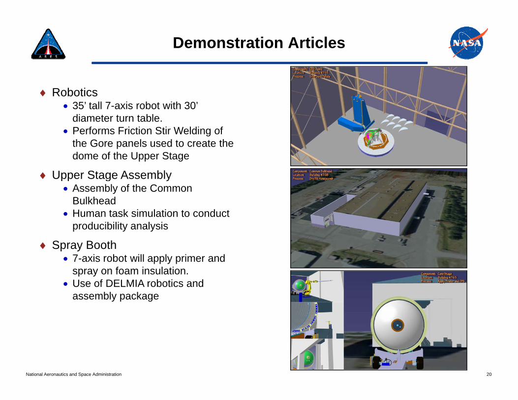
♦ Robotics• 35’ tall 7-axis robot with 30’
diameter turn table.• Performs Friction Stir Welding of
the Gore panels used to create the dome of the Upper Stage
♦ Upper Stage Assembly♦ Upper Stage Assembly• Assembly of the Common
Bulkhead• Human task simulation to conduct
producibility analysisproducibility analysis
♦ Spray Booth• 7-axis robot will apply primer and
spray on foam insulation.p y• Use of DELMIA robotics and
assembly package
20National Aeronautics and Space Administration

Outline
1. DELMIA History at MSFC 2. Constellation Program Overview3. Ares I Upper Stage4. Digital Manufacturing Implementation for Ares I US5. Problems/Challenges We’ve Faced6. Producibility/Simulation Analysis Examples
21National Aeronautics and Space Administration

Digital Manufacturing Implementation
♦First step was to migrate from D5 to V5• Developed a list of functions used in D5 which were required to exist in V5• DELMIA came in and we worked through this list• DELMIA came in and we worked through this list• Not all items existed in V5, but we made the decision to migrate to V5 and
retain some D5 licenses
♦ Industry Benchmarking♦ Industry Benchmarking• November 7-8, 2006
− Tank and Automotive Research Development and Engineering Center (TARDEC) and General Motor Product Development Center, Detroit, Michigan
• November 15 2006• November 15, 2006− Boeing Integrated Defense Systems, San Antonio, TX
• December 6-7, 2006− Boeing Commercial Group, Dreamliner Program (787), Seattle, WA
J 10 200• January 10, 2007− Boeing F-18 Program, St. Louis, MO
• January 24, 2007− Flexial Corporation, Cookeville, TN
22National Aeronautics and Space Administration

State of DM 18 Months Ago
MSFC IES09Fil B d D t StDDMS
Source of Design Data
File Based Data Storage
Stand AloneWorkstations
23National Aeronautics and Space Administration
Producibility AnalysesLegend•Manual•Automated

Current State
M d l B d I iDDMSSource of Design Data
Model-Based Instructions
Manufacturing HubS fSource of
Manufacturing DataStand AloneWorkstations
24National Aeronautics and Space Administration
Legend•Manual•Automated
Producibility Analysis

The Future State
Model-Based InstructionsDDMS
Source of Design Data
Manufacturing Hubg
Manufacturing E ti S tStand Alone
WorkstationsExecution System
25National Aeronautics and Space Administration
Legend•Manual•Automated
ProducibilityAnalysis

Outline
1. Constellation Program Overview2. Ares I Upper Stage3. DELMIA History at MSFC4. Digital Manufacturing Implementation for Ares I US5. Problems/Challenges We’ve Faced6. Producibility/Simulation Analysis Examples
26National Aeronautics and Space Administration

Problems/Challenges
♦Getting our Foot in the Door• We had to do a lot of selling• Had to get the buy-in from our Project Officeg y j• Also had to let the design teams realize the value we could bring to the table• Time spent : ~ 12-14 months
♦We’re NOT CARTOONISTS!O i l ti h b ll d i ti t ill t ti t• Our simulations have been called animations, cartoons, illustrations, etc.
• Constantly asked to provide “cartoons” for different presentations• Must play up your successes and tout the tool’s real capabilities
♦Non-homogeneous Environment♦Non homogeneous Environment• The design is created with Pro/E and housed inside Windchill database• The design changes without us knowing.• We’ve generated simulations, shown the results, and then been asked why
we were using outdated modelswe were using outdated models.
♦Design data in various locations• All of the US design is in DDMS• Designs for fixtures, tooling, etc. are stored in various other locations.
27National Aeronautics and Space Administration
g g• Impossible to keep up with it all

Problems/Challenges
♦ CAD Translation Problems• This is one of our biggest problems• Can take 4-7 days to translate an assembly with 20,000 parts
W ’ t i d th f ll i• We’ve tried the following:− 3DEvolution from Core Technologies− CADFix from ITI TranscenData− Theorem− Elysium (The new DELMIA translator as of R18)
MPP (Th ld DELMIA t l t R18)− MPP (The old DELMIA translator, pre-R18)• The best to date have been the DELMIA provided translators
♦ Not Working in a Fully Model-based Environment• Since NASA’s inception, the 2D drawing has been the standard.
M i f th t h b diffi lt• Moving from that has been difficult• For Ares I US, the decision has been made to move to a hybrid environment• Models will be provided; metal can be cut to those models• However, all notes and annotations will be on the drawings, NOT the model
L k f E t i M f t i E ti S t♦ Lack of a Enterprise Manufacturing Execution System• Visual Manufacturing used by our machine shop• Very antiquated interface and functionality• Does not capture electronic signatures• Does not offer an interface with DELMIA
28National Aeronautics and Space Administration
• Does not offer an interface with DELMIA

Problems/Challenges
♦Development of Model-Based Instructions and Standards• Many of the functions in V5 used to create Model-Based Instructions lack
desired functionalitydesired functionality.− 2D Annotated Views – Do not work in R17 or R18− Standard Libraries for Work Instruction Text – Can be created in V5, but not
modified− Shop Floor Interface – Window sizes have apparently been hard-coded; Hampers− Shop Floor Interface – Window sizes have apparently been hard-coded; Hampers
customization.• Using Panasonic Toughbooks on the Shop Floor. Delays from our IT group
in developing a standard software load which meets NASA IT Security i trequirements.
29National Aeronautics and Space Administration

Outline
1. DELMIA History at MSFC 2. Constellation Program Overview3. Ares I Upper Stage4. Digital Manufacturing Implementation for Ares I US5. Problems/Challenges We’ve Faced6. Producibility/Simulation Analysis Examples
30National Aeronautics and Space Administration

MSFC Simulations
31National Aeronautics and Space Administration

Ares I Upper Stage M&A
32National Aeronautics and Space Administration

33National Aeronautics and Space Administration
Thank You