Embed Size (px)
Citation preview

8/18/2019 Marine Propulsion for Small Crafts
http://slidepdf.com/reader/full/marine-propulsion-for-small-crafts 1/71
:;?
..5' - 2-
7Dpp
. .?
Marine
ropulsion
•
n
Small raft
TECHNICAL
PAPER FOR:
THE
SOCIETY
OF NAVAL
ARCHITECTS
AND MARINE ENGINEERS
SOUTHEAST SECTION
A POWERBOAT SYMPOSIUM
AND
SECTION MEETING
Miami Beach
February 19 and 20 1985
By :
DAVID F. BUTLER
BUTLER MARINE TECHNOLOGY
INC.
600 SOUTHEAST FIFTH COURT
POMPANO
BEACH FLORIDA
33060
305-781-7458
8/18/2019 Marine Propulsion for Small Crafts
http://slidepdf.com/reader/full/marine-propulsion-for-small-crafts 2/71
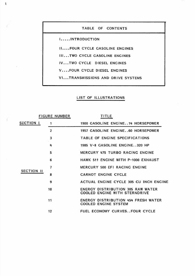
SECTION
TABLE
OF CONTENTS
I ••••• INTRODUCTION
II
FOUR CYCLE
GASOLINE
ENGINES
I l l TWO CYCLE
GASOLINE
ENGINES
IV TWO
CYCLE DIESEL ENGINES
V FOUR
CYCLE DIESEL
ENGINES
VI
TRANSMISSIONS AND
DRIVE
SYSTEMS
LIST
OF
ILLUSTRATIONS
FIGURE NUMBER
1
TITLE
1900 GASOLINE ENGINE ••
14
HORSEPOWER
2
4
5
6
7
1957 GASOLINE ENGINE •• 6 HORSEPOWER
TABLE
OF ENGINE SPECIFICATIONS
SECTION
II
1985
V 8
GASOLINE ENGINE •• 32 HP
MERCURY
475
TURBO
RACING
ENGINE
HAWK 511 ENGINE WITH P 1000
EXHAUST
MERCURY
5
EFI
RACING
ENGINE
CARNOT
ENGINE
CYCLE
9
1
11
12
ACTUAL
ENGINE CYCLE 3 5 CU INCH ENGINE
ENERGY DISTRIBUTION 3 5 RAW WATER
COOLED ENGINE WITH STERNDRIVE
ENERGY DISTRIBUTION 454 FRESH WATER
COOLED ENGINE SYSTEM
FUEL ECONOMY CURVES FOUR CYCLE

8/18/2019 Marine Propulsion for Small Crafts
http://slidepdf.com/reader/full/marine-propulsion-for-small-crafts 3/71
LIST OF ILLUSTRATIONS
CONTINUED)
fiGURE NUMBER
If
ITLE
13
TABLE OF TWO CYCLE ENGINE SPECIFICATION
SECTION
l l
14 TWO
CYCLE ENGINE DESIGN
15
ENGINE CYCLE
FOR TWO
CYCLE DESIGN
16
TABLE
OF
TWO
CYCLE DIESEL ENGINES
SECTION
IV
17
TWO
CYCLE SYTEM
OF
OPERATION
18
TURBOCHARGED
TWO
CYCLE DIESEL ENGINE
19
MARINE FOUR CYCLE DIESEL ENGINES
2
VOLVO TMD
4
DIESEL ENGINE
SECTION V
21 DETROIT DIESEL 8 2 LITER ENGINE
22
PERFORMANCE CURVES
8 2
LITER 28
BERTRAM)
23
CATERPILLAR
32 8 TA
CONSTRUCTION
24
MTU 6V-396 FOUR CYCLE DIESEL
25
MARINE TRANSMISSION -
GAS
26
VOLVO STERNDRIVE CONSTRUCTION
SECTION VI
27
ELEMENTS OF A MARINE DIESEL
28
ARNESON DRIVE

8/18/2019 Marine Propulsion for Small Crafts
http://slidepdf.com/reader/full/marine-propulsion-for-small-crafts 4/71
INTRODUCTION
At the turn of the 20th century, sail
and
steam were the only
motive power of significance on
the
yachting
scene and of these, sail
was
the overwhelming
choice. While powerful, fast steam yachts were
in
existance,
their numbers
were extremely
small. There were some
steam launches
with
small single-cylinder engines and simple upright
boilers, and
a
very
few
fast curisers
with tandem or
triple expansion
steam power
plants.
New types of propulsion were appearing in small
runabouts
- the
Naptha powerplants
an
offshoot
of steam
engine designs)
and
the infant gasoline engines.
There
was no
question
that sail dom
inated
the
yachting scene, far overshadowing
all
other means
of
propul
sion.
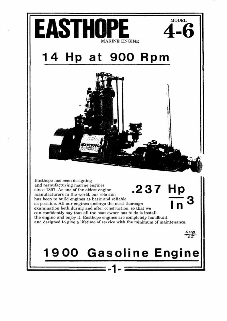
At the turn of the century
gasoline engines
for small launches
were typified by
the
Easthope
one
and two cylinder gasoline engines.
A
single-cylinder
model
is
shown in FIGURE ONE. The inlet
and
exhaust valves are driven by external push rods driving off the cam
shaft.
The
distributor is driven by exposed bevel
gears,
and
the
direct drive transmission is the ultimate in simplicity.
The
engines of
the
period were
typified
by long strokes, and
this
tended
to limit maximum RPM. This
engine
had a 3. 875
bore and
a 5-inch stroke. Displacement was 59 cubic inches, and maximum
power was
14 horsepower at
9
RPM.
The engine could also
idle
at
100 RPM which is incredibly slow. Specific power output was
1/4
horsepower per cubic
inch.
Some of the new racing
engines
discussed
later turn out 1. 4 horsepower per cubic inch while
screaming
away at
5 400 RPM.
World War I provided a tremendous push to engine technology •
By the
end
of
the
war,
water-cooled military aircraft
engines
had
become amazingly modern in concept and construction. Mercedes
with a straight
six and Hispano-Suiza
with a
V-8 both
had
reliable

8/18/2019 Marine Propulsion for Small Crafts
http://slidepdf.com/reader/full/marine-propulsion-for-small-crafts 5/71
engines over 3 horsepower. The Liberty aircraft engines in the
United
States
found
their way
into
racing boats, and the new
speed
records
and publicity did much to
popularize speedboats
in the
1920 s.
During
the
1930s
intense research
in
diesel
technology
took
place with the
development of powerful locomotives to replace
the
steam engines. Since steam locomotives
are
non-condensing,
the
overall
system efficiency was less than five
percent,
and the
potential
cost
savings
with diesel locomotives was enormous. By the beginning
of World War
II,
two and four cycle diesel engines in the sizes needed
for
landing craft
and submarines had
been developed
and were in low
volume production. World War
II gave
a
tremendous
push in all areas
of diesel technology,
and
many improvisations
were
required. General
Motors had
an
outstanding diesel in
the six
cylinder 71 series engine,
but many applications
required
more power.
Arrangements
were created
with
two and even four 6-71 engines driving a single transmission, and
by 1947
the
twin installations were able
to provide 4
HP
at
2000
RPM
for
yachting
applications.
In the post World War II
period
the
gasoline
engines specifically
designed for
marine applications were
gradually
dropped in favor of
the
new
overhead valve
automotive
engines
available
for
marine
con
versions.
These
engines were built in new, highly automated
plants
in
large production
volumes,
and
provided much higher power outputs
at reasonable cost
than
the older designs.
Diesel technology for yachts was pretty well dominated by
naturally aspirated designs in
both
two and four
cycle until
the early
1970s. The Detroit Diesel SV-71-TI and the Cummins
VT-370
became
popular engines for yachts in the
4
to 55 foot size, and pointed the
direction of
future development.
During
the past
decade, intense
research has lead to a flood of turbocharged diesel engines in many
configurations, ranging from turbocharged six-cylinder designs attached
to
sterndrives
up
to the
complex
turbocharged
and aftercooled V-12
and
V-16
diesels
available in the
9
to 2630 Horsepower range.
8/18/2019 Marine Propulsion for Small Crafts
http://slidepdf.com/reader/full/marine-propulsion-for-small-crafts 6/71
MODEL
4 6
MARINE ENGINE
14
Hp
at
900
Rpm
Easthope
has
been
designing
and manufacturing marine engines
since
1897. As one
of the
oldest engine
manufacturers in
the world our sole
aim
.237
Hp
has been
to build
engines as
basic
and
reliable
as
possible. All our
engines
undergo
the most
thorough
examination both during and
after
construction so
that
we
can
confidently
say that all the boat
owner has to do is
install
the
engine
and
enjoy it. Easthope engines
are
completely
handbuilt
n
and
designed to give a lifetime
of
service
with
the
minimum of maintenance
19
Gasoline Engine
1 ::::=====-1-

8/18/2019 Marine Propulsion for Small Crafts
http://slidepdf.com/reader/full/marine-propulsion-for-small-crafts 7/71
FOUR CYCLE GASOLINE ENGINES
The
small
gasoline
engine
shown
in
the
introduction
is
still
manufactured today with one important area of
change.
The ignition
systems at the
turn
of the century were a major source of unreliability,
and the little
Easthope
has a modern ignition system
and
alternator.
The
dampness
of the
marine
environment caused many serious
problems.
Rolls
Royce
in the famous Silver Ghost
series
went
to
two totally
independant ignition
systems
with two spark plugs per
cylinder.
Marine
engines were
also
available
with
this system, and the Easthope
Model 8-14
twin cylinder can
still be ordered with
both magneto
and
distributor
ignition
with two spark plugs per
cylinder.
Careful
maintenance
and good
ventilation
were
the
best
recommendations for
reliable
service
on
these
early
engines. The
Easthope
single-cylinder
developing
14
horsepower at 900 RPM is typical of the period.
This
little engine
could idle
at 100 RPM and the specific
power output,
at .237
HP
per cubic inch,
was
very modest. If
more
power was
required, a two cylinder model was available, providing
38
horsepower
at
1200 RPM. This was a later design which enclosed the valve
push
rods
inside
the
basic
engine
castings. The
engine
was
still
designed
with a common cast iron
sump which
provided the
line
of
strength
from the engine through the transmission, and the flywheel was huge
to
allow
idling
at 150 RPM. The
specific power
output
was
considerably
higher
at
.
32 HP
per
cubic
inch. These small economical engines
powered
thousands of launches
and
small runabouts early in
the
century.
They
were
far lighter and more fuel efficient than the steam powered
plants of the period and
eliminated
the
need for
a licensed steam engineer
and the need for shoveling
coal
to
stoke
the boiler on
a
hot summer's day.
A typical
marine engine used
from the mid-1930s
up into the
1960s is
shown
in FIGURE TWO. This is a Chris-Craft Model B of
1957 providing 6 horsepower at 3200 RPM. This type of engine
was

8/18/2019 Marine Propulsion for Small Crafts
http://slidepdf.com/reader/full/marine-propulsion-for-small-crafts 8/71
Chris Craft 6 0 h p marine
Here's a nother power-packed Chris-Craft 60-hp engine.
You'll find the Model B
w ll
deliver the power and econ
omy that you expect in ll Chris-Craft marine engines.
Satisfied users
of
Chris-Craft marine engines can tell
you about the remarkable performance they've been
getting. One boat designer says, "Several years ago I
designed a fast fishing boat that was powered with a
Chris-Craft marine engine. After serving 14 years, this
engine was removed
and
installed in another
boat-
60 Hp at
3200
133 u In
.45
and s still going strong
And,
he says, "the economy of upkeep and oper
ation of Chris-Craft marine engines has been truly
remarkable. For many years now,
at
my own boat yard,
I have installed Chris-Craft marine engines in new boats
and as replacements. None has ever given any trouble."
For
smooth, dependable power, low upkeep, long
life, boat owners all over the world have chosen this
Model B marine engine.
1957
Gasoline
Engine
2 ~
8/18/2019 Marine Propulsion for Small Crafts
http://slidepdf.com/reader/full/marine-propulsion-for-small-crafts 9/71
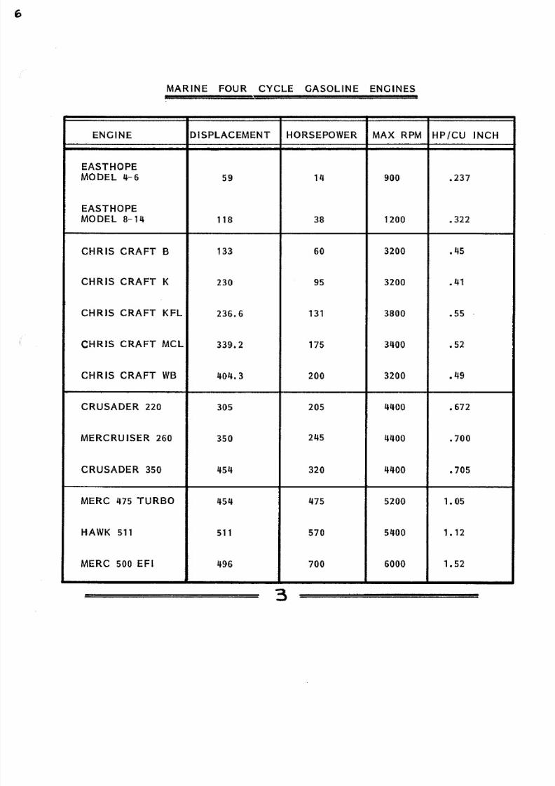
MARINE FOUR CYCLE GASOLINE ENGINES
ENGINE
DISPLACEMENT
HORSEPOWER
MAX
RPM
HP/CU INCH
EASTHOPE
MODEL
11 6
59 9
237
EASTHOPE
MODEL 8 111
118 38
12 322
CHRIS CRAFT
B
133
6 32 •
45
CHRIS
CRAFT
K
23
95
32 • 41
CHRIS
CRAFT
KFL
236 6
131 38
55
CHRIS CRAFT MCL
339 2 175
34 52
CHRIS
CRAFT WB
404 3
2 32 • 49
CRUSADER 22
3 5 2 5 44
• 67
MERCRU ISER 26
35
245
44 700
CRUSADER
35
454
32
44 705
MERC 475 TURBO
454
1175 52 1 05
HAWK
511 511
57 54
1
12
MERC 500 EFI
1196
7 6
1 52
3

8/18/2019 Marine Propulsion for Small Crafts
http://slidepdf.com/reader/full/marine-propulsion-for-small-crafts 10/71
FOUR CYCLE GASOLINE ENGINES
very
widely
used
In
the
small
Mahogany
Runabouts.
For
larger yachts
60
horsepower
was simply not
sufficient even
with the modest demands
of forty years
ago.
The
line
of engines
included a
six-cylinder
companion the Model K at 95
horsepower
with a very similar output
at
111 HP per cubic inch.
Cabin
cruisers
and high speed
runabouts
required still
more
power
and
this
need was met
by 1 increasing
maximum
RPM above
the
3200 limit
2
increasing displacement up to the maximum practical
limits in
six cylinders
The
model
WB
had
11011 cubic inches
or
67
.II
cubic
inches
per cylinder. 3
Use
of
multiple carburetors on the
engines. These fifty year
old
designs used Updraft
carburetors
with
a
vertical plate-type
flame
arrestor as
shown in FIGURE TWO,
and
a
pair
could
be mounted side by side feeding into a split intake manifold.
There was a V-8 monster available at about 7 liters capacity
but it was such a specialized engine it was too
expensive
for
normal
applications.
Most
large
yachts used
two
of the
175
or
200
horsepower
six
cylinder
engines and for the larger yachts over
fifty
feet three
engines were often installed.

8/18/2019 Marine Propulsion for Small Crafts
http://slidepdf.com/reader/full/marine-propulsion-for-small-crafts 11/71
VEE
EIGHT MARINE ENGINES
During the 1960s and 1970s the marine gasoline engines
changed from the In-line blocks designed as marine engines to
the conversion of the new powerful
overhead
valve
vee-eight
engines developed for automotive uses. Most of the current marine
engines
are based
on the
General Motors
series of
blocks
of
305
cubic inches
up to 454
cubic
inches. For race boat
applications,
heavy-duty
454 blocks with
the
four bolt main
bearing
design allow
horsepower outputs up into the astronomical
range.
Often these
engines
are
re-worked
with
oversize bores and
special
crankshafts
to
further
increase the
displacement to
the 500
cubic inch
range.
A comparison
of
the standard and high-performance vee-eight engines
is given below in the lower half
of
FIGURE THREE.
The
power outputs on the chart show the current
state of
the
art
with the large, strong automotive
blocks.
The Crusader 220
the Mercruiser 260 and the Crusader 350 are the standard models
used
in
90
percent of
the
inboard
cruisers
built today, and these
same
basic
engines are
used
in most of
the
stern
drive·
models. Typically,
the
305 and
350 blocks are used in
yachts under
30 feet,
and the
big
454 block is the workhorse for cruisers over 30 feet and in
performance
racing boats in
stern drive
configuration. All
of
the standard
engine
designs
give a
specific power output of about
•
70
horsepower per
cubic inch
of
displacement.
This is three times as
high
as the typical
engine
of
1900 and
55 higher than
the 1957 engine shown in FIGURE TWO.

8/18/2019 Marine Propulsion for Small Crafts
http://slidepdf.com/reader/full/marine-propulsion-for-small-crafts 12/71

8/18/2019 Marine Propulsion for Small Crafts
http://slidepdf.com/reader/full/marine-propulsion-for-small-crafts 13/71
TURBO-CHARGED GASOLINE ENGINES
The design
of a
turbo-charged gasoline engine based
on
the
454
cubic
Inch block Is shown In FIGURE FIVE. This model is
built
by the HI Performance
Division of
Mercruiser and provides
a power
output
of
just over one horsepower
per
cubic
inch of
displacement.
This is accomplished
by
mounting a turobcharger at
the end
of
each exhaust
manifold
and using the
two turbines
to power air
compressors, boosting the
incoming
air
in
the intake
manifold.
Turbocharging is
highly
successful
in
aircraft gasoline engines
and
in
marine diesels, but has really not been competitive
in
marine
gasoline engines. Aircraft
engines are designed
from
scratch to
meet
the stresses
of turbocharging,
and the 325 horsepower Continental
opposed
six,
for
example
can
stand
39 inches
of
mercury boost on
take
off
which
puts the pressure
in
the intake
manifold
at
almost
34
pounds per
square inch psia).
Such pressures
would blow a
con
ventional marine gasoline engine to
bits,
fracturing pistons, bending
rods and causing cracked heads and bearing failures.
The turbocharged
Mere
475
must
compromise
on
Intake boost
for
these
reasons, and the turbos cause restrictions
in
the exhaust
gas path.
TUNED EXHAUST
Another approach
is
to concentrate
on
getting
the
maximum
amount of
air
through
the
engine.
This
is
illustrated by the HAWK
511
engine in FIGURE
SIX.
·To
achieve the
54
brake horsepower,
all
the
passages in
the
cylinder
heads are carefully polished
with
rotary
grinders
to smooth
the
air flow oversize
intake
and
exhaust

8/18/2019 Marine Propulsion for Small Crafts
http://slidepdf.com/reader/full/marine-propulsion-for-small-crafts 14/71
475T
75
Hp
at
5200
5 Cu
Inches
1 05 Hp/Cu In
HI :·:PERFORMANCE PRODUCTS
2521 Bowen Street •
Oshkosh
WI 54901
Telephone (414) 231-9180. Extension 331. or 353
Tu rboc ha rged
SPECIFICATIONS
Horsepower
475
Cylinders V-8
Displacement
454
Cu. ln.
Bore Stroke 4.2Sx4.00
Compression Rallo
7:1
Induction Single 4 Barrel
Fu
II
Throllle Range 5200
Drive Unit TRS
MC II SSM
or MC Ill
SSM
A BRUNSWICK
COMPANY
783
Gas Engine
~ 5 ~

8/18/2019 Marine Propulsion for Small Crafts
http://slidepdf.com/reader/full/marine-propulsion-for-small-crafts 15/71
TUNED EXHAUST (CONTINUED)
valves
are fitted
and
special matched
sets
of
pistons
and
machined-
-over connecting rods are assembled
to
special crankshafts.
This
power output
can be
further
raised to 570
brake
horsepower by the
use of
Stelling
exhaust headers. An
engine
and transmission
set up
in full racing dress
costs about
27,500 due to the tremendous
input
of skilled
hand labor and
the very expensive materials used In
con
struction.
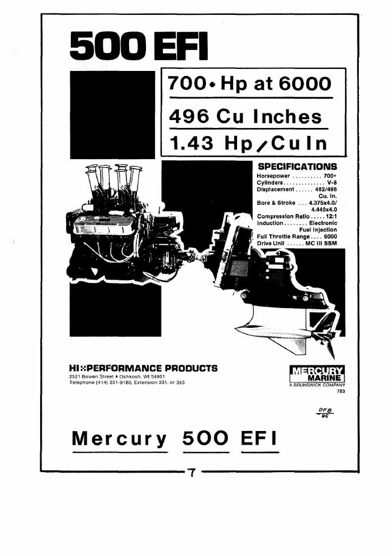
TUNED INTAKE SYSTEM
About the highest power
output
per cubic inch of displacement
in marine gasoline engines is achieved using the approach shown in
FIGURE SEVEN. Four tall stacks bring the air smoothly into
each
of
two huge
Holley
carburetors.
The exhaust would
be
similarly
treated
with
huge
cast aluminum exhaust manifolds capable of handling the
exhaust gas with the absolute minimum pressure
drop.
This is done
with
large
polished
passages and
a
short
large-diameter path
for
the exhaust gas
directly
aft
and
through the
transom.
In this
illustration
the exhaust
headers
have
been removed to show the double
carburetor
and
intake air
configuration.
The exhaust
headers
would
be similar
to
FIGURE
SIX.
In the racing
classes
of engines each
engine
has a huge input of skilled mechanical
effort
and this includes
Individual
dynamometer
testing of each engine. The
700
horsepower
rating
means a guarantee of
over
700 brake horsepower
centrified
with
each engine. This
amounts
to
over
1. 5 horsepower
per
cubic inch
or
in the
current
technology
nearly 90
horsepower per liter of dis
placement.

8/18/2019 Marine Propulsion for Small Crafts
http://slidepdf.com/reader/full/marine-propulsion-for-small-crafts 16/71
DOUBLE ENDED HOLLEY CARBURETOR
WATER CONNECTION TO PORT
EXHAUST S Y S T E M ~
PORT EXHAUST MANIFOLD ..;
ENGINE LUBRICATING OIL
f i tTER
TO
STARTER 12 VOLT)
COOLING LINES
HIGH VOLTAGE WIRES TO SPARKPLUCS
TYPE HIGH VOLTAGE COIL
TYPE SPECIALLY BALANCED DISTRIBUTOR
ARRESTOR
~ F ~
PUMP VENT LINE
DISTRIBUTION MANIFOLD
COOLING WATER HOSE TO EXHAUST MANIF
LINES ·TO BOTH ENDS OF
THE
CAR
ALUMINUM
VALVE
ROCKER COVER
S
CAST ALUMINUM WATER COOLED
EXHAUST MANIFOLD
FUEL SUPPLY FROM PRESSURE CO
SEA WATER PUMP DRIVING COOLIN
WATER INTO ENGINE
WATER LINE TO
OIL
COOLER
H WK
NGIN S
TYPE
FUEL
PUMP
HIGH CAPACITY OIL PAN
WITH INTERNAL BAFFLES
ST RBO RD
SIDE
Jo
8/18/2019 Marine Propulsion for Small Crafts
http://slidepdf.com/reader/full/marine-propulsion-for-small-crafts 17/71
EFI
700•
Hp
at
6000
496 Cu Inches
1 43 Hp/CU In
HI
: :PERFORMANCE PRODUCTS
2521 Bowen Street • Oshkosh WI 54901
Telephone {414) 231-9180. Extension 331.
or
353
SPECIFICATIONS
Horsepower 700
Cylinders
V·8
Displacement 482/496
Cu. ln.
Bore Stroke 4.375x4.0/
4.440x4.0
Compression Ratio
12:1
lnducllon Eleclronic
Fuel Injection
Full Throtl le Range 6000
Drive Unll MC
Ill
SSM
i i
:tiH :9
MARINE
A BRUNSWICK COMPANY
78
Mercury 5 EFI
~ 7

8/18/2019 Marine Propulsion for Small Crafts
http://slidepdf.com/reader/full/marine-propulsion-for-small-crafts 18/71

8/18/2019 Marine Propulsion for Small Crafts
http://slidepdf.com/reader/full/marine-propulsion-for-small-crafts 19/71
CHANCEABLE CYLINDER
HEAD WHICH IS {
1)
HOT
2) INSULATING 3) OLD
q) INSULATING
PISTON,
WHICH
IS A
FIT IN THE CYLINDER
•
si
COMPRESSION STROKE
DI B TIC COMPRESSION
WITH NO HEAT TRANSFER
arnot
EXPANSION STROKE
lNG MEDIUM HEATED
BY HOT CYLINDER HEAD
CONSTANT TEMPERATURE )
EXPANSION STROKE
NO
TRANSFER
WORKING MEDIUM COOLED
BY COLD CYLINDER HEAD )
Volume •
Engine ycle
s
PERFECTLY SMOOT
CYLINDER WALLS W
ARE LSO PERFECT
INSULATORS { NO

8/18/2019 Marine Propulsion for Small Crafts
http://slidepdf.com/reader/full/marine-propulsion-for-small-crafts 20/71
THERMODYNAMIC EFFICIENCY (CONTINUED}
efficiency of 24 does not seem too good and leads to the need for
a
fundamental
look at
the
operating
principles of the
4-cycle gasoline
engine.
The
most
efficient possible cycle for
a
piston engine
was
postulated by
a
Frenchman,
Nicholas
Carnot,
in 1820.
The
Carnot
Cycle is shown in FIGURE EIGHT and is described
as
follows:
A
cylinder
contains
a
working
mixture .
Starting at
point
a in
the cycle,
the
gas
is at
pressure
P1 and temperature T 1
•
The cylinder head
is a hot
surface at temperature T1,
and
the
heat
transfer
is so instantaneous and so
perfect
that T 1 is
maintained
as
the piston
moves from
point a
to
point
b doing mechanical
work
on
the
piston.
At
point
b
the hot cylinder head
is
suddenly replaced by
a perfectly insulated head, and
the
cylinder walls
and piston are
also
perfectly insulated. While the process
a-b
is ISOTHERMAL
(constant temperature} the process b-e
is ADIABATIC.
The gas
has
continued
to
do
useful work on
the piston
and
the
mechanical
energy
is
represented
by a drop in
the
internal energy of the gas
in
the cylinder.
At
point
c
a cold cylinder head
at
a
temperature
T 2 is
suddenly placed
on
the engine, and as the piston compresses the
gas,
the
cold
head
absorbs energy
so
that
the
work
of
compression
is far less
than that of
expansion.
This
is
another
ISOTHERMAL
process.
At
point d an insulating head
is
put
on
the
cylinder
and the gas
is
compressed
adiabatically
back
to
point a .

8/18/2019 Marine Propulsion for Small Crafts
http://slidepdf.com/reader/full/marine-propulsion-for-small-crafts 21/71
ACTUAL OPERATING CYCLES
The operating
cycle
of
a
typical
3 5
cubic
inch V-8
marine
engine is
shown
in FIGURE NINE The
curve
shown is built on
the best
available check
point
from
laboratory dynamometer
data,
but the shape of the
curves
have been
simplified
to
make math
ematical analysis
easier.
COMPRESSION STROKE
The
compression
stroke
swoops smoothly
upward to peak
pressure
and
temperature
in
the
Carnot cycle. In
real
life
the
performance is very different
due
to
massive
heat
transfer
from
the compressed charge
to
the cold
cylinder
walls.
Theoretically,
a
compression
ratio of B 5 to 1 would achieve a
pressure
of 250
PSI, and a
thermature of
750
degrees.
With a real engine,
there
is
massive
heat
transfer
as 43 cubic inch
charge
is crammed
into
a
1
/2-inch
high
space
at
the
top
of the
cylinder,
and
actual
pressures
of
about
175
PSI
and temperatures of
5
degrees are
achieved
in
an
engine in
good
mechanical
condition.
POWER STROKE
About
2 degrees before
the
piston
reaches top
dead
center
TDC).
the spark plug fires.
The
combustion process burns the
charge
to a pressure of
about
850 PSI, and the central flame tem
perature is at about 2500 degrees. Both the temperature and
pressure
are much less than theoretical calculations
due
to
massive
heat
transfer.
Thermodynamically, the
flame is
burning
in a large
diameter
chamber
only 1
/2-inch
high with ice cold
walls. The
heat
transfer possibilities
are
enormous.
The cylinder
and
heat
must
be

8/18/2019 Marine Propulsion for Small Crafts
http://slidepdf.com/reader/full/marine-propulsion-for-small-crafts 22/71
VOLVO TMD
4 TURBOCHARGED DIESEL
ENGINE
PRE COMBUSTION CHAMBER DETAIL
FIGURE
2

8/18/2019 Marine Propulsion for Small Crafts
http://slidepdf.com/reader/full/marine-propulsion-for-small-crafts 23/71
soo
·
• 6 0 0 \
I
....
UOT
Pressure \1
v ~ ~ ~ ~
4
00
1 \.. -1----
p
s I
I ' - , ~ . ' 0
.... ~ X P A
NSION . .
~ . . . , .I ·e.-
'
,..
. t o ' r ~ t -
'I FSI
e s h ~ _
= r
~ - ~ - = - - ' . J - ~ ~ ' f . . . . C ' • •=-·::.-.,.
--....;;
F l ' f e ~ l •
_ _ •
THO• •
- - L - - - 1
P
1
' -
1-_Z - ~ --' j-e .I= I ·
s
1
-
J:N.TA
0
5
10
IS
Volume
20
25 SO
'35 ..co
4S
Cubic Inches •
O·F·IS
"'as
Pressure-
Volume
Curves
4 Cycle
' - ---- ----

8/18/2019 Marine Propulsion for Small Crafts
http://slidepdf.com/reader/full/marine-propulsion-for-small-crafts 24/71
POWER STROKE CONTINUED)
kept
so
cold
since
a raw
water
cooled
engine cannot
allow
the
salt
water
to
get over
150
degrees or the
salt starts to
precipitate out
of
solution.
The
20
degrees of travel
between spark plug firing
and top
dead
center
occurs in less than a millisecond at 400 RPM. With
typical
flame
speeds
of 150 feet
per
second, the burning occurs
basically
with
the piston near top dead center, and FIGURE NINE
shows
a
straight
pressure
rise
to simplify
calculations.
If
the
fuel
is
not
of high enough octane, there will be detonation which is
easy
to
hear
in a car
and far more
difficult to
detect
in a marine
engine.
Fortunately, knock will rarely cause mechanical damage
to an engine and
is easily solved
by
1
proper
grade
of leaded
fuel; 2 retarding
the spark ignition
closer
to
top dead
center.
Pre-ignition is an entirely different story. If hot spots
develop
in a chamber, the
compressed
charge may light
off
before
the
plug
fires.
Flame
speeds of
1000
feet
per
second
give
no
audible
warning, but
can
cause severe engine destruction. The
flame
fronts
and pressures are building
at
sonic velocity
as
the
piston
is still
coming
up
and peak
pressures go so
high that damage is inevitable.
Good
engine
cooling
and avoidance
of long maximum RPM operation
are
the best
preventatives.
EXHAUST STROKE
On a normal marine
engine
the exhaust valve opens about
50 degrees before bottom
dead center BDC). On
racing engines this
is moved
back
toward
80 degrees
before BDC.
The
remaining pressure

8/18/2019 Marine Propulsion for Small Crafts
http://slidepdf.com/reader/full/marine-propulsion-for-small-crafts 25/71
6
EXHAUST STROKE CONTINUED)
drives the gas through the exhaust
valve opening
at
sonic velocity
and with the exhaust typically at 1500 degrees, the opportunity for
heating
the
exhaust valve is tremendous.
The pressure
remains well
above atmospheric during
the
entire exhaust stroke, and pumping the hot exhaust
gas
through
the
slot around the
exhaust
valve represents negative work
and
another
loss
in the
operating
cycle. The exhaust valve closes
about
15 degrees
after
top
dead
center.
INTAKE STROKE
About 15 degrees
before top dead
center
the
intake valves
open, resulting
in about a 30° period when both intake and exhaust
valves are
open.
With
tuned intake and exhaust
systems,
the
moving exhaust
gas
and intake air columns continue to move properly,
even
with
both valves open.
The
entire induction system of the gasoline engine operates
below
atmospheric
pressure. A vacuum
gauge
in
the intake
manifold
would show up
to
15 inches of mercury
under
low
demand
operation
2000 RPM
but
only 2 - 4 inches of
mercury
when
the engine
is
running
wide
open at
4400 RPM. The critical operation it
at
wide
open throttle where
only
a small pressure differential
must
provide
huge
air flows through the carburetor. With a Rochester
Quadrijet
4-barrel carburetor, 387 cubic feet
per
minute
will flow
even
at
low
differentials. The large
Holley models can move 1050 CFM
of
air
through four barrels in a
racing engine.
At the end of the intake
stroke, there is a
cylinder
full
of
air at
ambient temperature and
at
a pressure of 12.7
pounds
per
square
inch
absolute.
8/18/2019 Marine Propulsion for Small Crafts
http://slidepdf.com/reader/full/marine-propulsion-for-small-crafts 26/71
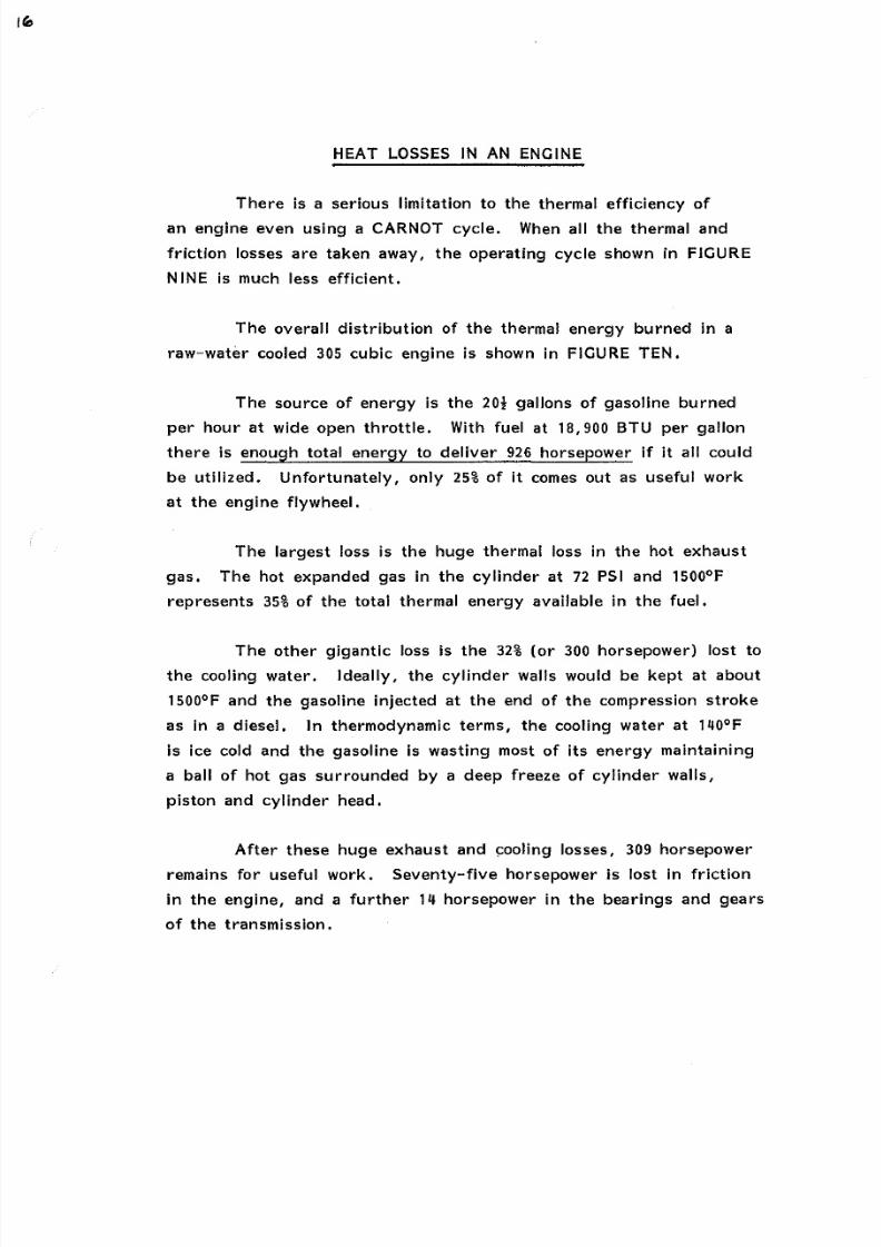
HEAT LOSSES
IN AN
ENGINE
There
is
a
serious
limitation
to
the
thermal
efficiency
of
an engine even using a CARNOT cycle. When all the
thermal
and
friction losses are taken away,
the
operating cycle
shown
in FIGURE
NINE is much
less
efficient.
The overall
distribution
of
the thermal
energy
burned
in a
raw-water cooled
305 cubic engine
is shown in FIGURE TEN.
The
source
of energy
is
the 201 gallons of
gasoline
burned
per
hour at wide
open throttle.
With fuel at 18 900 BTU
per gallon
there is
enough total
energy
to
deliver 926 horsepower
if
it all
could
be
utilized. Unfortunately, only 25 of it comes out
as
useful work
at the
engine
flywheel.
The largest
loss
is the huge
thermal loss
in
the
hot
exhaust
gas.
The
hot
expanded gas in the cylinder at
72
PSI and 1500°F
represents 35
of
the total thermal energy
available in
the
fuel.
The
other
gigantic loss is the 32 or 300
horsepower)
lost to
the
cooling
water. Ideally,
the cylinder walls would be
kept at about
1500°F and the gasoline injected
at the
end of the compression
stroke
as
in a diesel. In thermodynamic terms,
the
cooling water at 140°F
is ice cold and the gasoline is
wasting
most of its energy maintaining
a ball of hot gas
surrounded
by a deep
freeze
of cylinder
walls,
piston and cylinder
head.
After these huge exhaust and cooling losses, 309 horsepower
remains
for
useful
work.
Seventy-five horsepower is lost in friction
in the
engine, and a
further
14 horsepower in
the
bearings and
gears
of
the transmission.

8/18/2019 Marine Propulsion for Small Crafts
http://slidepdf.com/reader/full/marine-propulsion-for-small-crafts 27/71
'
900
800
~ ~ o o i
W
i
I I
6-soo;
o l
~ ~ 4
ol
HE T
LOST
TO
EXH
AtiST
GRS 35
'3'21 HP
HEAT
LOST
- ENE:R GV
L O S S E S
.
RAW
WATER
.
COOLED
G S
E N G I N E W I T H
OUTD < : \Ve
TO C.OO
LING
WATei'C. '3'2
300 HP
o:
H E ~ T
I ~ 3 Q CONTENT
T ~ A N S M I S S I O N
LOSS
14
HP
I
o 9 3 6 ~ p
I
200
I
\00
THRUST T o MoVE
6oAT
154
HP
=
I Ocro
Burt er?..
.... 8
Losses-
Raw
Water
ooled
as
11 10
l
8/18/2019 Marine Propulsion for Small Crafts
http://slidepdf.com/reader/full/marine-propulsion-for-small-crafts 28/71
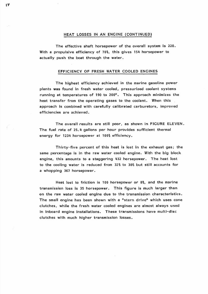
HEAT LOSSES IN AN ENGINE CONTINUED)
The
effective shaft horsepower of the overall system is 220.
With a propulsive efficiency of 70 ,
this
gives
5 horsepower
to
actually push the
boat
through the water.
EFFICIENCY OF FRESH
WATER
COOLED ENGINES
The
highest
efficiency achieved in the
marine
gasoline power
plants was found
in
fresh water cooled, pressurized
coolant
systems
running
at temperatures of 190 to 200°. This approach minimizes
the
heat
transfer
from
the operating gases
to the coolant. When
this
approach
is
combined
with
carefully calibrated
carburetors, improved
efficiencies are achieved.
The overall results
are still
poor, as
shown in FIGURE ELEVEN.
The fuel rate
of
25.11 gallons per hour provides sufficient thermal
energy
for
12311 horsepower
at 100
efficiency.
Thirty-five percent
of
this
heat
is
lost
in
the exhaust gas; the
same percentage
is in
the
raw
water
cooled
engine.
With the big
block
engine, this amounts to a
staggering
32
horsepower. The heat
lost
to the cooling water is reduced from 32 to
30
but still accounts for
a whopping
367
horsepower.
Heat
lost
to friction is 100
horsepower
or
8 , and the marine
transmission
loss is
35
horsepower.
This figure
is much larger than
on the raw
water
cooled engine due to the transmission characteristics.
The small
engine has
been shown with a stern drive which
uses
cone
clutches,
while the
fresh
water cooled engines are almost always used
in
inboard engine installations. These transmissions have multi-disc
clutches with much
higher
transmission losses.

8/18/2019 Marine Propulsion for Small Crafts
http://slidepdf.com/reader/full/marine-propulsion-for-small-crafts 29/71
HE'AT
CoNTI N T
O FUEL
1200
1000
l
800
U
3
0 OO
Q
U
Ill
l
400
0
: t
200
1'2
HP
HEAT
LOST TO
EXHAUST
GAS
35 -=432HP
I I E ~ T
.
LOST
To
CoOLING-
WATeR.
= :,aoHP
P o P o L . SIVE LoSS aSHP
(33 OF SHP
T H ~ ~ S T TO H o V e
YACHT
190
HP =
t5%
E N E ~ G (
LOSSES
F ~ e S H
W T E ~
Cocn
.
ED
G S O L I N E
I N 8 o A ~ D
b.F.B
8'i -8S'

8/18/2019 Marine Propulsion for Small Crafts
http://slidepdf.com/reader/full/marine-propulsion-for-small-crafts 30/71
EFFICIENCY OF FRESH WATER COOLED ENGINES CONTINUED)
The shaft
horsepower
available
is 300,
or 24
oy
the
thermal
energy of the fuel. with a 70 propulsive efficiency we
have
17
of
the energy
content of
the
fuel
available to
thrust
the boat
through
the water.
FUEL CONSUMPTION CURVES
Fuel
consumption curves
for a typical 305 cubic inch marine
engine
is
shown
in FIGURE TWELVE.
The
gallons
per
hour
are
shown
in the
lower
solid
line.
At
idle
the engine
burns
about
gallons
per hour and consumption rises to 201 gallons per
hour
delivering
220
brake
horsepower at 4400 RPM.
A curve of
fuel economy
is shown
in
the upper curve on
the left-hand side. Fuel economy Is measured in pounds of fuel
required
per
brake horsepower-hour.
Thus
at 1000 RPM it requires
2.27 pounds of fuel for each
brake
horsepower for an hour. In the
most
efficient
range from 2500 to 3500 RPM, the engine requires only
6/10 pound
of fuel per brake horsepower-hour.
At wide-open throttle
the fuel consumption
rises
to about . 65 lb. per horsepower hour to
deliver
about 200 shaft horsepower
at
4400 RPM.

8/18/2019 Marine Propulsion for Small Crafts
http://slidepdf.com/reader/full/marine-propulsion-for-small-crafts 31/71
Fuel
20
Gal
5
Hour
•
5
0
0
FUEL
ECONOMY- MAIZ.INE V-S
305
1N3
8 45:
I c R ENGINe:
Z:l T
•
-
,69
2oo
Shaf
ISO
H P
100
50
----
·
0
5
1 0 0 0 1500
zooo
2500 ~ 0 0 0 3500 ~ 4 5 0 0
Engine R.P.M. •
Fuel
Economy Curves
o e
1 2

8/18/2019 Marine Propulsion for Small Crafts
http://slidepdf.com/reader/full/marine-propulsion-for-small-crafts 32/71
FUTURE TRENDS
Future trends in four-cycle gasoline engine technology are
visible today
in
the
automotive
developments
in
the
United
States,
Japan and
Europe.
FOUR VALVE DESIGNS
Extremely high power outputs are being achieved
by
designing
with four valves per cylinder. As heads manufactured this way become
available in automotive
engines, they
will move
over
into marine
very quickly. If effect, the four valve design opens up
the
intake
and
exhaust flow allowing specific outputs to exceed
horsepower per
cubic inch in
standard engines.
TURBOCHARGING
Turbos are being added to small displacement
automotive
engines
today. When larger
displacement engines
are
designed to handle
the
higher maximum
pressures
developed by turbochargers, they will be
adapted
for
marine
use.
LIGHT WEIGHT ENGINES
Considerably higher
power
outputs will be available in the
future
with
the
same
external engine size. The
new
lost
foam
casting process
gives
very
accurate
block
castings
with typical
cylinder
wall
thicknesses of
• 230 inches.
Larger bores,
more
efficient
water passages and higher weight are
coming from
this
casting technique, particularly when
used
with OSTEO-STENETIC
heat
treatment
procedures
for machined
castings,
such
as connecting
rods
and crankshafts.
8/18/2019 Marine Propulsion for Small Crafts
http://slidepdf.com/reader/full/marine-propulsion-for-small-crafts 33/71
FUTURE TRENDS · CONTINUED)
FUEL INJECTION
Another area
is
to increase the burning
efficiency
by reducing
the fuel-air
ratio. Intense
research in this area is yielding excellent
results. Electronic sensors
are being
mounted
in
the engines to
monitor
operating conditions. The use of
fuel injection
systems
monitoring
individual cylinders performance are in the works in
automotive
applications
and
when
this
is
combined
with
knock sensors
which
adjust
the timing of the spark plugs
for individual
cylinders
we
are
pretty close
to optimum efficiency.

8/18/2019 Marine Propulsion for Small Crafts
http://slidepdf.com/reader/full/marine-propulsion-for-small-crafts 34/71
TWO
CYCLE
MARINE
GASOLINE
POWER
.ENGINES
The two cycle marine gasoline engine was first applied
as
a
small,
low-powered
outboard
motor to propel
rowboats
at
low speed.
The intent
was
to
replace
hours
of
hard
work
rowing
with
a small
portable
engine which would accomplish the same purpose. Many
inventors participated around the turn of the
century,
but the
Evinrude
system turned
out
the
best, and these
heavy,
low-powered,
single-cylinder
motors became widely used. In the 1920s, the emphasis
shifted to more
powerful
opposed piston
twin-cylinder
models.
By
mounting the cylinders opposite
each
other, the vibration was consid
erably
reduced
and
higher power
with lighter
weight was achieved.
Eighty years
of development has resulted in huge improvements
in compression
ratios,
fuel economy, reliability, smoothness and power
to
weight ratios.
A
table of
current
engines
is shown in FIGURE
THIRTEEN. The OMC SAIL DRIVE is a specialized small
engine
designed
to drive heavy
loads
at low speed. t is included in the
chart since it
shows
that when current two-cycle
technology
is
applied to a workboat -type design problem, the maximum RPM
and
power
output per
cubic
inch
are cut
way back in
the
interest
of dur
ability
and
reliability
in
handling heavy loads.
The
maximum
engine
RPM
and
the specific power output are
typical
of engines of
forty
years ago.
Normally,
outboard
engines as a class are utilized on the
lightest and
smallest classes of
recreational boats.
The basic
designs
have
been
adjusted for this
with extremely high
power
to weight ratios
and high
specific
power outputs. The Johnson 75 horsepower engine,
for example, weighs 540 pounds, where a s imilar _power level in a
four
cycle
stern drive or inboard engine configuration weighs
almost
exactly
double this weight. The price is paid in durability. In commercial
service
fishing
outboard motors
are
often
replaced
yearly.
In fresh
water,
outboard
engines
last for
many years and in the modest hourly
usage of
many salt
water boats careful flushing of the engines after
use
results in
adequate service
life.

8/18/2019 Marine Propulsion for Small Crafts
http://slidepdf.com/reader/full/marine-propulsion-for-small-crafts 35/71
DISPLACEMENT
ENGINE
CUBIC
INCHES HORSEPOWER
MAX
RPM HP/CU
IN
OMC SAIL
DRIVE
31.8 15 3300
• 47
MERCURY 60 49.8 60
5800
1.20
JOHNSON 120 110 120 6000 1. 09
JOHNSON 275 220 275 6000
1. 25
EVINRUDE V 8
FORMULA ONE 214
400 10
000
1. 92
MARINE TWO CYCLE GASOLINE ENGINES
~ 1 3

8/18/2019 Marine Propulsion for Small Crafts
http://slidepdf.com/reader/full/marine-propulsion-for-small-crafts 36/71
TWO
CYCLE MARINE GASOLINE
POWER
ENGINES (CONTINUED)
The highest
power
output in outboard engines is
achieved
in
the
newest Formula One
engines typified by
the Evinrude model
shown
last
on FIGURE THIRTEEN. The heart of
the
engine is a
214 cubic
inch
V-8 block specially manufactured and hand
assembled.
Racing
pistons in
matched
and balanced
sets
are assembled to racing
rods
and the assembly topped off
with a
two-barrel
carburetor for
each
cylinder.
When mounted on a Formula One hydroplane, typically
one built of wood and
weighing
under 400 pounds, these engines can
drive the boat to
15
miles per hour. The engines alone
run about
22,000 a
copy
and
must
be
torn
down
and rebuilt
after
about seven
hours of running
at
full
racing
speed.
TWO CYCLE ENGINE DESIGN
The
basic
assembly of
a two
cycle
outboard is shown in
FIGURE FOURTEEN. The
fresh
charge is
drawn
into the crankcase
through a one-way reed valve during the movement of the piston
upward. There are
free-flowing
carburetors,
often one
per cylinder,
on
the high output engines and the crankcase serves as a receiver
for
the fresh charge.
As
the
piston
drives down
on the
power
stroke, the reed valves close and pressure builds up under the
piston. This
positive
pressure is used to scavenge the old combustion
gases
from the
cylinder as
the
piston
approaches bottom
dead
center.
This
configuration, with a vertical
crankshaft,
has been developed
over the years
into
a
very
specialized form of engine design.
The
gas dynamics become very critical to success. The time
for
the
exhaust gases
to
be
swept out and
replaced by
a
fresh
charge
are
VERY short, and
the
pressure differentials available to accomplish
the flows
are quite
low. At full
speed,
the
racing engine
is turning
at
10,000 RPM, or
167
times a SECOND.
This
means that from the time
the
exhaust port is uncovered until bottom
dead
center is one millisecond
( 1/1000
second).
Even a
regular outboard,
such
as
the 275
horsepower
model, at 6000 RPM has only 1/350 second for the entire exhaust and

8/18/2019 Marine Propulsion for Small Crafts
http://slidepdf.com/reader/full/marine-propulsion-for-small-crafts 37/71
RIDGE O TOP OF PISTON
TO
HELP CYLINDER
SP RK PLUG
EXHAUST C S
EXHAUST M N I FOLD
FRESH MIXTURE FLOWING
CYLINDER
CRANKCASE
FILLED
WITH
COMPRESSED GASOLINE AIR
MIXTURE
VENTURI
REED
TYPE
CHECK
VALVES
CONNECTING ROD
r Two
Cycle Engine Design
4
AIR
INTAKE
FOR
ENGINE

8/18/2019 Marine Propulsion for Small Crafts
http://slidepdf.com/reader/full/marine-propulsion-for-small-crafts 38/71
2 4
TWO
CYCLE MARINE GASOLINE POWER ENGINES CONTINUED)
recharging of
the cylinder. In a
camera
this
is
considered a fast
shutter speed, but in these engines it is the
total
time allowed
for
complete
purging
of
the cylinder.
It is small
wonder
that
about
1/4 of
the
incoming charge
mixes
with
the
exhaust and is
lost
during
this
very rapid transfer.
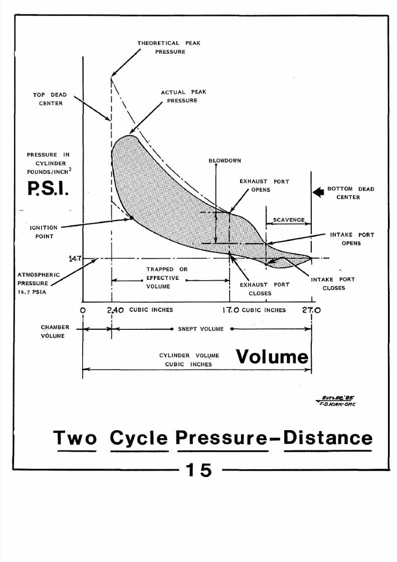
PRESSURE-DISTANCE CURVES
The pressure-distance relationships in a
modern
two-cycle
outboard are shown in FIGURE FIFTEEN. The
cylinder
volume is
27
cubic inches
with
the
piston
at
bottom
dead
center.
During
the
compression
stroke,
fresh
fuel-air
mixture flows
into
the cylinder
from the compressed charge in the crankcase. At a volume of about
22 cubic inches the intake port is cut off. The
piston
continues
upward and some of the
fresh
charge inevitably moves out the exhaust
port until it
is closed
off
when
17 cubic
inches
of cylinder volume
remains. The
trapped or
effective
volume is
the swept
volume
between 17 cubic inches and the 2.4 cubic inches
remaining at
top
dead
center.
During this
compression
period, the charge compresses
toward a theoretical 270
PSI; however,
the
spark plug
fires before
top dead
center
is reaches and
the
pressure
rises
quite rapidly as the
piston gets near TDC.
POWER
STROKE
Theoretically the
charge
would
burn to
a pressure
close to
900
PSI,
but this
theoretical
peak is
chopped
way down by the
burning rate of the
fuel
and heat
transfer
in
tiny space above
the
piston. It is amazing that the engines work at all, since the
game
is
to build
a 2500
degree fire
in a
chamber
1/4-inch
high with
a cold
cylinder
head above and a cold piston below.
Whether
the
piston
is
at
150
or
300 degrees
makes little
difference when the
fire
is
2200
degrees hotter.
The
losses to
heat
transfer have to
be
enormous.
8/18/2019 Marine Propulsion for Small Crafts
http://slidepdf.com/reader/full/marine-propulsion-for-small-crafts 39/71
TOP
DEAD
CENTER
PRESSURE IN
CYLINDER
POUNDS/INCH
2
P S I
THEORETICAL PEAK
/
I
I
PRESSURE
ACTUAL
PEAK
PRESSURE
BLOV1DO>WN
EXHAUST PORT
t11
BOTTOM
DEAD
CENTER
IGNITION
;.. -
SCAVENGE
POINT
PRESSURE
l i j 7
PSIA
CHAMBER
v LUME
0
Two
I
TRAPPED OR
1
EFFECTIVE
-----...,
VOLUME
EXHAUST PORT
CLOSES
INTAKE PORT
OPENS
PORT
CLOSES
<? 40
I
CUBIC
INCHES 17.0
CUBIC
INCHES
27 0
I
J
I
SWEPT VOLUME
CYLINDER VOLl JME
CUBIC INCHES
olume
6on tg:
Btr
T . O . f < I ~ I · O H C
Cycle
Pressure Distance
15

8/18/2019 Marine Propulsion for Small Crafts
http://slidepdf.com/reader/full/marine-propulsion-for-small-crafts 40/71
TWO
CYCLE MARINE GASOLINE
POWER
ENGINES CONTINUED)
During
the
power
stroke, the
useful work
is
done
by
the gas
shoving
the piston downward.
At
the
beginning of the
stroke,
the
force exceeds two tons, and
by
the end of the stroke
just
before the exhaust port opens,
the force is typically
about
1/2
ton.
EXHAUST STOKE
When the
piston reaches
a swept volume
of 7 cubic inches
the
exhaust
port
opens, and the
remaining
gas pressure
blows
down
into
the
exhaust manifold. With careful gas dynamics tuning the
remaining
pressure is slightly over atmospheric when
the
intake port
is uncovered.
Obviously,
if the remaining pressure is too
high,
the
exhaust gas
will blow
into the intake system and the
column
of gas
will develop a
dynamic
motion in the wrong direction.
The trick
is
to have the exhaust system
pressure
down just about even with the
compressed
intake
charge when
the port opens.
As
the exhaust
pressure
continues
to
decline,
the
compressed
incoming
charge
starts
to flow
into
the cylinder, sweeping up one
cylinder
wall and driving
the remaining
exhaust
gas ahead
into the exhaust
manifold.
The fresh
charge continues to flow in past bottom
dead
center and until the
intake port is
cut
off by the rising
piston,
The cycle then continues,
cutting
off
the exhaust port
and
compressing the charge until the
spark plug fires.
Modern two cycle
engines
represent some of the most
sophisticated
gas dynamics in
any
engine technology
today.
The
entire intake and exhaust systems are
tuned
to take advantage
of the
kinetic
energy of the
moving
gas
column
and achieve gas
flow
rates which are incredible in the time spans available.
These
modern
two
cycle designs provide extremely high power outputs
for
the engine
weight, and also
very high power
outputs
for
the engine displacement.

8/18/2019 Marine Propulsion for Small Crafts
http://slidepdf.com/reader/full/marine-propulsion-for-small-crafts 41/71
TWO
CYCLE DIESEL ENGINES
The main booster
of
the two cycle diesel principle for small
craft has been the General Motors
Corporation
with the
Detroit
Diesel
line
of
marine engines
and
the Electromotive
Division which
manufactures mid-sized
diesels
for
locomotives
and
commercial vessels
over
8 feet in length.
During World War II
thousands
of the Detroit Diesel
six-cylinder
71-series engines were installed in small landing craft. For larger
ships dual
engine
installations
driving a single shaft were developed
and when
even
more power was needed
an arrangement consisting
of
four
six-cylinder
engines
driving
a common
transmission
was
developed. By 1959 this concept had been refined so
that
the dual
engines
could
provide
47
horsepower and
special
Quad units using
HV 8 injectors could supply 1008 Brake Horsepower for yachting
use.
Transmission losses
were
fairly
high with this complex
arrange
ment and the weight was also
high at six
tons.
In
the
1960s
the
basic line-up of
two-cycle Detroit
Diesels
was
built
on
the
71
series engines
ranging
from
two-cylinder
to
sixteen-cylinder
models.
The
basic
workhorse 6-71 engine
was
available in a turbocharged
version
with a
power
output of 310
horsepower at 2300 RPM. This represented a 25 percent increase
in
power
and
this engine
in
both naturally
aspirated and turbocharged
versions
became popular in
cruisers
of forty feet and up.
In
the early
1970s
the power outputs had risen slightly
and a new series of
smaller
53 cubic
inch
per
cylinder
engines had
been
added
to the
line. The
8V-53-N
became
a
very
popular engine
for yachts in the
thirty-five
to forty-five foot range. A
powerful
turbocharged engine had been
added
in the 8V-71-T providing
425
HP and this became a widely used engine in yachts of the forty to
fifty-five
foot range.
8/18/2019 Marine Propulsion for Small Crafts
http://slidepdf.com/reader/full/marine-propulsion-for-small-crafts 42/71
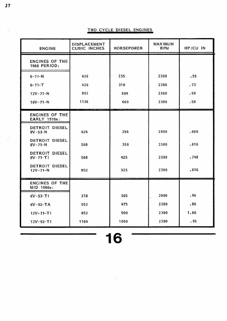
TWO
CYCLE DIESEL
ENGINES
DISPLACEMENT
MAXIMUM
ENGINE
CUBIC INCHES
HORSEPOWER RPM
HP/CU
IN
ENGINES OF
THE
196
PERIOD:
6 71 N 426
235
23
.55
6 71 T
426 31
23 .73
12V 71 N
852
5 4
23 .59
16V 71 N
1136
66
23
.58
ENGINES OF
THE
EARLY 1970s:
DETROIT
DIESEL
BV 53 N
424
256
28 • 6 4
DETROIT DIESEL
BV 71 N
568
35
23 • 616
DETROIT DIESEL
BV 71 TI 568
425
23 • 748
DETROIT DIESEL
12V 71 N
852
525
23 • 616
ENGINES OF
THE
MID
198 s:
6V 53 T I 318
3 5
28
.96
6V 92 TA
552
475
23
.86
12V 71 TI
852
9
23
1 6
12V 92 TI
11 4
1 5
23
.95
16

8/18/2019 Marine Propulsion for Small Crafts
http://slidepdf.com/reader/full/marine-propulsion-for-small-crafts 43/71
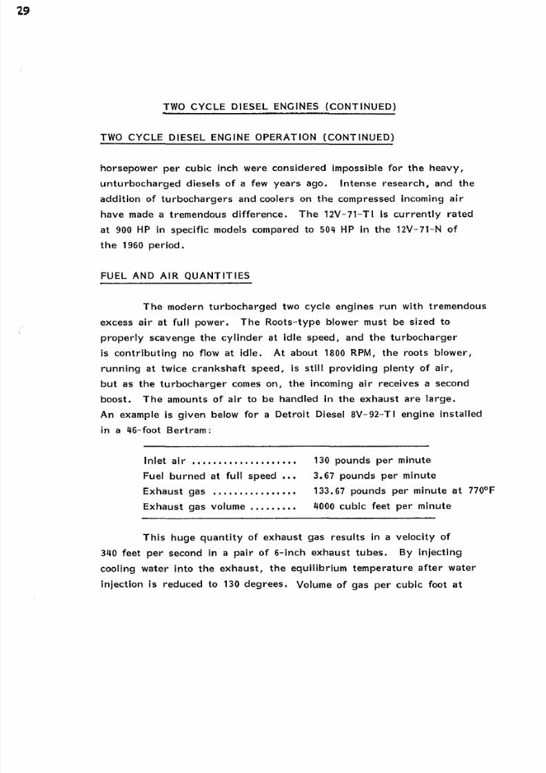
TWO CYCLE DIESEL ENGINES CONTINUED)
TWO CYCLE DIESEL ENGINE OPERATION
A two
cycle diesel works on
a slightly different
method
than
the
outboard
engines. The
basic principles are shown in
FIGURE SEVENTEEN. Four
exhaust valves are installed
in
the
cylinder head, with a fuel injector mounted in the center. The
left-hand
illustration shows the intake and exhaust phase. A
powerful
roots
blower
is
gear-driven
from the camshaft
and
provides
a
positive
pressure
in
the
intake
manifold. When
the
piston gets
close
to bottom dead center
(BDC),
the exhaust valves
open and
the remaining pressure
in
the
cylinder
blows down into
the exhaust manifold.
The
incoming air enters
through
a ring of
ports around the bottom of the cylinder, and the positive pressure
in the intake manifold is used to give a
torrent
of air
rising
vertically
to
clear
the
cylinder. The time
for
clearing
the
cylinder
is
about 5
milliseconds
at
2300 RPM, far longer than
the
time
for
change in an
outboard engine 1-1/2 milliseconds). The cylinder in a
Detroit
Diesel is
also
far
larger than the outboard designs. Since
this is
a diesel, the incoming
air
has no fuel
and excess
air simply blows
and causes no
losses.
The middle illustration shows the piston rising on
the
com-
pression
stroke, and
at 17
to 1 compression, this
results
in a pressure
of
about 600 PSI at top dead
center. About
2 degrees before top
dead
center, the
fuel
injector
starts blasting in a fine mist of fuel
oil
at
about
1150
PSI.
The
injection
stroke
typically
continues
for
3
degrees
at
full load and would be
cut
off early
under part
load
operation. With
the
two
cycle
diesel,
each
downward
stroke of the
piston is a power stroke, and this has allowed the very high power
outputs developed in recent
years. Power
outputs of •86 to 1. 6

8/18/2019 Marine Propulsion for Small Crafts
http://slidepdf.com/reader/full/marine-propulsion-for-small-crafts 44/71
Exhaust
and Intake
Stroke
Compression
Stroke 2
Power
TWO CYCLE DIESEL OPER TION
1 7
8/18/2019 Marine Propulsion for Small Crafts
http://slidepdf.com/reader/full/marine-propulsion-for-small-crafts 45/71

8/18/2019 Marine Propulsion for Small Crafts
http://slidepdf.com/reader/full/marine-propulsion-for-small-crafts 46/71
CAMSHAFT WITH ACCESSORY
DRIVES ON BOTH ENOS
PUMP CIRCUL TING FRESH WATER
THROUGH BLOCK AND HEADS
ACCESSORY DRIVE
BELTS OFF
urbocharged
wo
Cycle
IR
COMPRESSOR
DRIVEN BY
TURBOCHARGER
ENGINE DRIV EN COMPRESSOR
WITH
COUNTERWEIGHTS
HEAD WITH
EXHAUST VALVES
UN
IT
INJECTORS
6
PSI
INPUT
115 PSI INJECTION TO CYLINDER
PISTON IN REPLACEABLE
C ST
IRON
CYLINDER
ASSEMBLY
Diesel
Construction
8

8/18/2019 Marine Propulsion for Small Crafts
http://slidepdf.com/reader/full/marine-propulsion-for-small-crafts 47/71
TWO CYCLE DIESEL ENGINES CONTINUED)
FUEL AND AIR QUANTITIES CONTINUED)
130 degrees is cut in half to 5 cubic
feet
per pound
and the
velocity
of gas in
single 8-inch
tubes is
down to 98 feet per
second.
EXHAUST GAS TEMPERATURES
Diesel
engines
are
very
efficient compared
to gasoline
particularly at
part
loads.
While
the
gas engine
must have
a fuel
air mixture within specific
limits
at
all speeds
the diesel can run
extremely lean at low speeds providing just enough energy to
over
come
internal
friction.
This can be
seen in some
tests
run
with
a
Detroit
Diesel
8V-92-TI engine.
TEMPERATURE OF
EXHAUST GAS COOLING WATER JUST
ENGINE RPM TEMPERATURE BEFORE DUMPING
IN
EXHAUST
OF
OF
520 250 130
800
420 128
1000 520
124
1400
625
122
1800
670 120
2300 710
109

8/18/2019 Marine Propulsion for Small Crafts
http://slidepdf.com/reader/full/marine-propulsion-for-small-crafts 48/71
FOUR-CYCLE DIESEL ENGINES
In contrast
to
the two-cycle
diesels,
there are many
manufacturers
offering four-cycle
engines.
A few of the most
popular engines are shown in FIGURE NINETEEN.
VOLVO TMD 4
AND
TAMD
4
In the 1970s, Volvo introduced a series of six-cylinder
diesels suitable for
small
boats,
all
based
on
an in-line
block
of
219 cubic inches. The Volvo engines were available either with
conventional
transmissions
or
sterndrives, and
are
used
in many
small
yachts
in the 2 to 35-foot
range. The
design
of
the
engine
is
shown
in FIGURE TWENTY, together
with
the pre-combustion
chamber . The
engine
is shown with a turbocharger
and
intake
air compressor mounted at the aft end of the block,
and
the illus
tration
also
shows
a
clever transmission approach.
The
inboard
transmission is built from the basic gear
and
clutch assemblies from
the Volvo
sterndrive,
thus
giving
a
high
commonality
of parts
between
inboard
and
sterndrive installations. The
engines were offered in
naturally aspirated versions at 85
SHP,
turbocharged at 13
HP,
and turbocharged/aftercooled
at
165
HP.
The turbocharged versions
have become very popular in small boats in the 2 to 30-foot lengths.
PRE-COMBUSTION CHAMBER
The pre-combustion chamber, shown in the small insert, is
a system
used
on many small diesels,
such as
the
Mercedes automotive
engines.
It
provides
quieter operation
and ease
of starting
at
a small
trade-off
in efficiency. Basically, the piston
rams
the compressed
air
into the small
anti-chamber,
which is
fitted
with
both
a fuel injector
and
a glow plug .
To
start the engine, a heavy, 12-volt electrical
current
is applied to the glow plug which becomes red
hot.
As
the
engine is

8/18/2019 Marine Propulsion for Small Crafts
http://slidepdf.com/reader/full/marine-propulsion-for-small-crafts 49/71
MARINE
FOUR CYCLE
DIESEL ENGINES
DISPLACEMENT MAX
HORSEPOWER
ENGINE
CUBIC INCHES
HORSEPOWER RPM PER CU IN
VOLVO TAMD 4
219
165 3600 .75
CUMMINS VT 370
785
37 3 .47
CUMMINS VT 555M 555
32 3000 .576
DETROIT DIESEL
8.2
LITER
5 8
24
3200
• 47
PERKINS
T 6. 3544 M)
354
24
2800 .68
CATERPILLAR
3208 TA
636
375
2800
.59
MTU VEE TWELVE 2892
1960
2100 .68
12V
396
TB 93
========= 9===========

8/18/2019 Marine Propulsion for Small Crafts
http://slidepdf.com/reader/full/marine-propulsion-for-small-crafts 50/71
PRE-COMBUSTION CHAMBER CONTINUED)
cranked, the compressed
air flows
over the plug and is
heated,
and
the
injector blasts the fine mist of
fuel
directly on
the
plug.
The compact chamber gives
a small
volume for the
combustion
to
take place
efficiently,
and
as
the pressure rises, the
gas flows
out of the cavity and drives the piston
downward.
There is a
small loss of
efficiency
due
to gas
friction
and heat transfer
as
the charge
flows in and out of
the chamber
at
very high
speed.
DIESEL INJECTOR TECHNOLOGY
The
technology
of fuel injection, particularly on small
diesel
engines
is
just short of incredible.
An 8 Kilowatt
Onan generator,
for example
is powered by a small 14 horsepower four
cycle
diesel.
Turning
at a steady 1800 RPM
hour after hour
it burns
.90 gallons
of
fuel per hour. This must be
divided up
into 162,000 separate
injections
of 1/1800 Ounce
apiece.To
measure such
microscopic quan-
tities, pressurize the
fuel
to
2000
PSI,
and
inject
in a
period
of
less
than 3
milliseconds .
0028
seconds)
takes
incredible precision.
The
typical four cycle
fuel
injector works
with
far larger
quantities. A
Caterpillar
3208 TA at wide open
throttle burns just
under 2 gallons per hour to develop
375
horsepower. This
works
out to 2 pounds per
minute,
which must be split up
into
11,200
separate injections
at
2800 RPM. Each full throttle
injection meters
1/338
ounce .
003
ounce), pressurizes it,
and
injects into
the
cylinder
in
about
a
15
degree
rotation
of the crankshaft. The
time
for
this
cycle
is shown
in
typical
figures in
the Illustration below.
The overall
injection
starts about 18 degrees before top dead center TDC), but since the

8/18/2019 Marine Propulsion for Small Crafts
http://slidepdf.com/reader/full/marine-propulsion-for-small-crafts 51/71
DIESEL INJECTOR TECHNOLOGY CONTINUED)
TYPICAL FUEL INJECTOR PRESSURE TIME CURVE
PRESSURE RISE
FULL THROTTLE
PRESSURE RISE
PART LOAD
10°
TYPICAL
IGNITION .__.w-
DELAY
18
DEGREES BTDC
PEAK
PRESSURE 1150 PSI TO
4500 PSI DEPENDING
ON
DESIGN
3000 TO 3500° TRANSIENT
TEMPERATURES
COMBUSTION
45 DEGREES AFTER TDC
Injector
plunger
Is
cam driven there
Is
a pressure buildup In the
system during the
cam
rise. The bulk of the
fuel Is
Injected
between
1
degrees
before
TDC, and shortly
after
TDC. On part throttle
operation the
metering system Is designed to
cut
off early,
truncating
the
Injection cycle. Peak pressure
vary
widely. Detroit Diesel, with
the
unit
Injector
system has a cam driven rocker arm driving on top
of
the
plunger, and
with
such
a
short
system
pressures
as
low
as
1150
PSI
are used.
Four cyCle designs
usually
have long fuel
injection lines
from the pump
to
the injector,
and
pressures
of 25 PSI to 4500 PSI
are
typically
used
to
give fast injection, and compensate for the
slight
expansion of the steel lines
under
impact
pressure.

8/18/2019 Marine Propulsion for Small Crafts
http://slidepdf.com/reader/full/marine-propulsion-for-small-crafts 52/71
CUMMINS VT-370 FOUR CYCLE DIESEL ENGINE
In
the
early 1970s there
were very
few turbocharged diesel
engines available. One outstanding
engine
was the Cummins
VT-370
which provided 370 horsepower at
3000 RPM. Installed in large
yachts
such as the
Chris-Craft
47-foot Commanders, these engines provided
high power output
with
relatively quiet operation. Sound level
tests
in
the Salon
above
the engine
room
showed decibel readings
8 dBA
quieter
than competitive engines and
on
a long
cruise, this
made a
tremendous difference. Fuel economy in turbocharged
four-cycle
diesels
is
good, and
many
of
these
47-foot
yachts
are
still in
steady
operation,
prized
by their
owners
for
an
excellent balance
of
power,
quiet
operation,
relative economy and durability. One advantage of
the turbocharged
diesels was the ability
to
run
comfortably
all day
on
a cruise
RPM
about 200 below maximum, giving a cruise
speed
in the
25 MPH range.
CUMMINS VT-555M SERIES ENGINE
In
the
1970s Cummins
brought
out a series
of
555
cubic inch
engines
for yachts in the
30
to 40 foot range. Over the past
decade,
these
engines
have grown
from
the original
205 horsepower naturally
aspirated
version
to the Big
Cam
turbocharged current
models
providing 320
HP
at 3000 RPM, for a specific power output of
.576
HP/cubic inch.
This
represents
a
growth
of over
55
in
power output
over the .37 HP/cubic inch available on the original engines.
DETROIT DIESEL
8.2
LITER ENGINES
The 8.
2 liter engine
represents
the
first
small four-cycle
Detroit
Diesel engine in
many years. Originally
offered in
the
early
1980s as a naturally aspirated engine
at
just over 200
HP, it is
in the
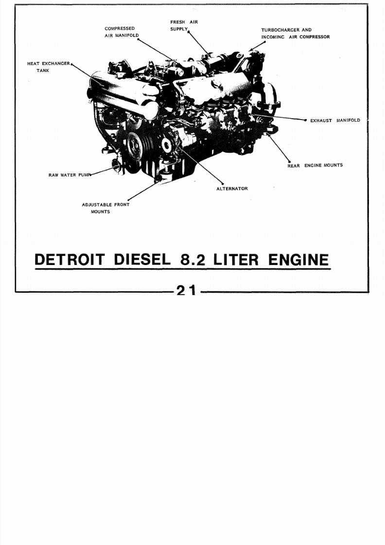
8/18/2019 Marine Propulsion for Small Crafts
http://slidepdf.com/reader/full/marine-propulsion-for-small-crafts 53/71
HE T EXCH NGER
T NK
COMPRESSED
DJUST BLE
FRONT
MOUNTS
FRESH IR
SUPPLY
LTERN TOR
TURBOCH RGER ND
IR COMPRESSOR
EXH UST M NIFOLD
RE R ENGINE MOUNTS
ETROIT IESEL
8 2
LITER ENGINE
2

8/18/2019 Marine Propulsion for Small Crafts
http://slidepdf.com/reader/full/marine-propulsion-for-small-crafts 54/71
DETROIT DIESEL 8.2 LITER ENGINES CONTINUED)
growth stage with
several
turbocharged marine conversions by
distributors
offered in 1982. The current
engine
factory built
with a single
centrally mounted
turbocharger is
shown
in FIGURE
TWENTY ONE.
The
performance of
a
pair
of
prototype
B. 2
liter
engines in
a Bertram
28
is
shown
in FIGURE TWENTY TWO. A set of curves in
this
format should
be
developed for every new engine installation
in
a
yacht. The
plot
of
MPH
vs
RPM
covers the cruising range
when
the
yacht
is fully up on
plane and
gives the
owner valuable range
vs
speed
information. Since hull friction varies as the square of the
speed
it is
not
too surprising to
see
that
the best
fuel economy
will be
achieved at
the lowest planing speed. In this case it is
1. 9 MPG in the 1600 to 1900 range. In an interesting parallel test
with
this
same model yacht
the diesel
fuel economy was 50
better
than
the
performance
with a
pair
of the 235 HP two
cycle gasoline
engines. In both cases I ran each boat over a 60-mile course
similarly
loaded over a
weekend. The outboard engines gave
a
higher
top speed
but the
diesels
really
shine
in
the
field of fuel economy.
PERKINS T 6,3544 (M) SIX CYLINDER DIESEL
An
example
of the results of a
long
development
and refinement
process
is the
Perkins
line of six
cylinder diesels.
A
rugged
354
cubic
inch
block is the
heart
of
the
engine and
the
basic version with a
Brog-Warner transmission
provides
135
horsepower at
2800 RPM.
After
a
decade of development and refinement the
latest
versions can
pour
out 77 more horsepower through turbocharging the
integration
of
large
capacity coolers and careful design of
the
induction and exhaust
air
flow. From a
specific
output of •38 HP
/cubic
inch the power has
grown
to
.68
HP/cubic inch
In
the
T 6.3544
(M}
model

8/18/2019 Marine Propulsion for Small Crafts
http://slidepdf.com/reader/full/marine-propulsion-for-small-crafts 55/71
E
o
CD
m
~
CD
,)
c:::
o
E
0
Q
a

8/18/2019 Marine Propulsion for Small Crafts
http://slidepdf.com/reader/full/marine-propulsion-for-small-crafts 56/71
TURBOCHARGER
COMPRESSOR INLET
V LVE
TR IN ; ; :o
EXHAUST V LVE
EXHAUST MANIFOLD
PISTON WITH
CHAMBER IN TOP
CONNECTING
RO
aterpillar
Four
ycle
HIGH PRESSURE FUEL
INJECTtON PUMP
FILTERS
INJECTOR
i •HEAT
EXCHANGER
LUBRIC TING OIL PUMP
Diesel Design
3

8/18/2019 Marine Propulsion for Small Crafts
http://slidepdf.com/reader/full/marine-propulsion-for-small-crafts 57/71
CATERPILLAR 3208 TA FOUR-CYCLE DIESELS
Caterpillar has
followed a similar development program with
the 636 cubic Inch V-8 line of
engines.
Originally introduced in
the mid-1970s at 210 HP, the
power output
had grown through
turbocharging
and
design refinement to 25 HP by 1980. This
grew
to 300 HP,
and
the addition
of aftercooling
the induction
air and the
use
of larger oil coolers allowed the power output to
rise
to 375 at 2800 RPM. This represents a growth from 210 HP
•
33
H P
/cubic inch)
to
375 HP
in the same
636 cubic inches. The
path
is
not
always
smooth.
The
maximum
pressures
developed by
turbocharging
could not
be
handled
by the
original
636
cubic
inch
block,
and
a very time
consuming and expensive
redesign was
required to
strengthen
all of the key elements sufficiently to allow
a 7 percent growth in power output to .575
HP/cubic inch.
MTU 396 SERIES ENGINES
The
highest
powered
diesels engines
currently in
general
use on
American yachts are the
MTU
line
of six
to
sixteen cylinder four cycle
diesels.
MTU represents a combine
of
old line German diesel
manufacturers
including
M.A.N.,
Maybach,
and
Mercedes Benz. M.A.N. has traditiona lly
been
strong In the
huge
three
story direct connected marine diesels.
The largest, a 12 cylinder, develops 56,160 horsepower, or 4680 HP
per cylinder turning
at less than
100 RPM.
The MTU six-cylinder engine is
shown
in FIGURE TWENTY
FOUR.
The
V-12 is
basically
two
six cylinder blocks bolted end
to
end, so the construction details are similar. Two
intake
and
two
exhaust
valves
per cylinder
are
fitted
with a fuel
injector
mounted
in the
center,·oHhe cylinder head
between the
four valves.
The design
is so compact
that recesses must be
machined
into
the
top
of
each
piston to
allow
the
valves to
open
with the
piston
at
top
dead
center. A Bosch in-line fuel
injection pump
is mounted in the center
between the
banks
of cylinders,
and
is gear driven from the camshaft.
High strength steel distribution lines carry the 2500 PSI
injection
fuel
from the pump to the individual
injectors.

8/18/2019 Marine Propulsion for Small Crafts
http://slidepdf.com/reader/full/marine-propulsion-for-small-crafts 58/71
EXHAUST OUTLET
HIGH PRESSURE FUEL
AIR INTAKE
MANIFOLD
COOLANT TANK WITH
HEAT EXCHANGER
GEAR TRAIN TO DRIVE
FUEL INJECTION PUMP
FRONT ENG
MOUNT
CAMSHAFT DRIVING VALVE
TRAIN
THROUGH ROLLER
FOLLOWERS ON PUSHRODS
GEAR DRIVEN
OIL PUMP
Four Cycle
MTU
OIL
P N
WITH
BAFFLES
Model
4
CRANKSHAFT WITH
COUNTERWEIGHTS
396
EXHAUST OUTLET
INTAKE
AND
EXHAUST VALVES
CYLINDER
INJECTION VALVE IN
CENTER
OF
CYLINDER
EXHAUST VALVE
WATER COOLED
EXHAUST M N I FOLD
REAR ENGINE
MOUNT
11T UIDF8
s
Engine
8/18/2019 Marine Propulsion for Small Crafts
http://slidepdf.com/reader/full/marine-propulsion-for-small-crafts 59/71
MTU
396
SERIES ENGINES CONTINUED)
At
the
end of each
cylinder
bank a turbocharger is installed
in a water cooled housing. The gas exhausts from the turbocharger
upward and
the compressed incoming air flows in toward the
engine
centerline through a cooler
and
then forward into a
pair of
intake
distribution
manifolds.
The MTU twelve cylinder
engine can provide
1930
horsepower
at 2100 RPM,
for
a
specific
power
output of
•
67
horsepower per
cubic inch. These engines
or the Detroit Diesel
12V-92-TA models
are
becoming poular in
yachts
in
the
55
to 9
foot
size. Higher
power
levels are available but the
cost
escalates rapidly.
The MTY 16V-396-TB63 can provide 2610 horsepower at 2100 RPM, and
this is accomplished in
an
engine just
over
five
tons
in weight. High
powered American diesels such
as
the Detroit Diesel 16V-149-TI have
primarily
been
designed
for commercial
service and turn
out 1600 BHP
at
1900 RPM in commercial trim
and
up to 2000 BHP modified for
yachting
use. Weight without marine gear
for
these
engines
is
just
under
six
tons.
The
difference is the
MTU focus
on military
appli-
cations
with a
high value
on
minimum
size and weight compared to
the American commercial objectives
of
moderate cost with extended
service life and minimum maintenance expense.

8/18/2019 Marine Propulsion for Small Crafts
http://slidepdf.com/reader/full/marine-propulsion-for-small-crafts 60/71
MARINE DRIVE SYSTEMS
Most
early
marine gasoline
engines were
built
using
a common
base for the
engine and
transmission. This type of
design is shown
in the Easthope
engine
in FIGURE ONE. A short drive shaft bridges
the space between the
two
units.
A manual
lever
was used to engage
the
forward
or reverse gear set, and generally these small
slow-turning
engines
required
no
reduction. The
huge flywheel,
required
to
allow
idling
at
100 RPM dominates the front of the engine
and
weighs more
than the entire transmission
assembly.
As engines became more
powerful
and
manufacturing
more
specialized,
the
use
of a separate transmission assembly bolted to
the engine flywheel housing became the accepted method of construction.
A modern in-line transmission manufactured by Borg-Warner is shown
in FIGURE TWENTY FIVE. Since engine flywheels differ in diameter,
an adapter
plate
is
bolted to
the flywheel housing and
the
transmission
input shaft is splined to
the crankshaft.
At
the
front of
the assembly
a gear-type oil
pump
is
mounted.
Since
this
is
always
rotating with
the
.engine,
it
provides
a
constant
supply
of
high
pressure
lubricating
oil
to
operate,
lubricate
and cool
the transmission.
CLUTCHES
There
is a large diameter clutch assembly
located
behind
the
oil pump.
There
are
only
a few elements in the ·clutch pack since
the
large diameter
give
excellent torque transmission
characteristics.
The clutch pack
is
engaged by
bringing
high-pressure oil into a
large diameter piston
area. The
piston is just forward of
the
clutch
pack
in the illustration, and
when
150 to 200 PSI oil operates
on
the
ring-shaped piston
surface, the
forward
gear
clutch locks up
very
tightly.
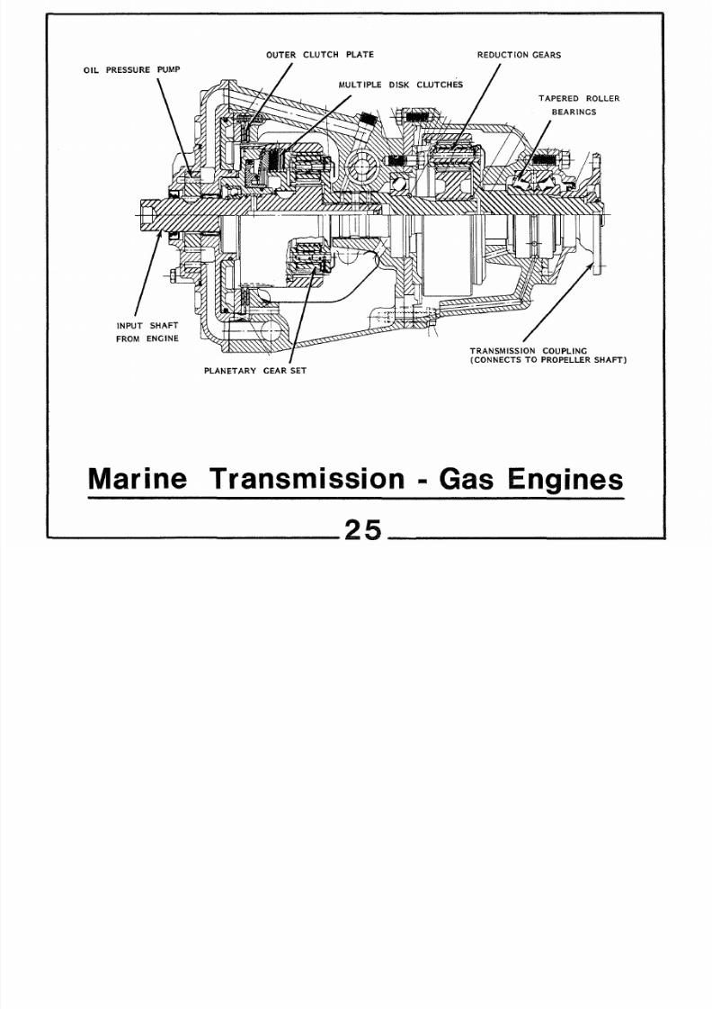
8/18/2019 Marine Propulsion for Small Crafts
http://slidepdf.com/reader/full/marine-propulsion-for-small-crafts 61/71
OIL
PRESSURE PUMP
INPUT SHAFT
FROM ENGINE
Marine
OUTER CLUTCH PLATE
MULTIPLE
DISK
CLUTCHES
PLANETARY
GE R SET
REDUCTION GE RS
T PERED ROLLER
BEARINGS
TR NSMISSION COUPLING
{CONNECTS TO PROPELLER SHAFT
Transmission Gas Engines
25
___

8/18/2019 Marine Propulsion for Small Crafts
http://slidepdf.com/reader/full/marine-propulsion-for-small-crafts 62/71
0
MARINE DRIVE SYSTEMS CONTINUED)
CLUTCHES CONTINUED)
A
multiple
disk clutch
pack is shown
behind the
large
clutch assembly. While smaller in diameter, it has more elements
to provide the torque transmission required. This
pack is
built
into
a planetary
gear set.
FORWARD AND REVERSE
Examination
of FIGURE TWENTY FIVE will show
that
there
are actually three distinct shafts between input and
output.
The
input
shaft is
locked to the engine
and the forward planetary gear
set
spins
at engine
speed.
It is a characteristic of planetary sets
to spin freely, with the small gears
walking
around the internal
gear and the external gear with
no
power output. To go into
FORWARD, the large diameter clutch is used to lock all the elements
of the planetary together. The middle shaft then turns at engine
speed,
and
the
yacht
is in
forward
gear.
When
reverse
is
desired,
the
outer clutch is released, and the small clutch pack engaged.
Under these circumstances,
the
small planetary gears reverse the
motion of
their carrier so that the center
of
the
shaft rotates in
the
reverse
direction.
REDUCTION GEARS
Bolted on
to the aft end of the transmission is a set of
reduction gears. In
small,
light yachts this
can
be eliminated,
but
normally
1. 5 to 1
or
2 to 1 reduction gears
are
fitted to yachts above
24
feet
in length.
As
yachts get
to 4 feet,
a reduction of 2. 5
to
1
needs to
be
considered in the propeller calculations to give the best

8/18/2019 Marine Propulsion for Small Crafts
http://slidepdf.com/reader/full/marine-propulsion-for-small-crafts 63/71

8/18/2019 Marine Propulsion for Small Crafts
http://slidepdf.com/reader/full/marine-propulsion-for-small-crafts 64/71
UPPER B LL BE RINGS
CONE CLUTCHES FOR
FORW RD ND REVERSE
EXH UST P TH
C VIT TION
TRIM T B
PROPELLER ON
SPLINED SH FT
TILLER RM WHICH
TURNS ENTIRE
LOWER
STERN DRIVE SSEMBLY
TR NSOM
OF
Y CHT
BEVEL GE RS ND BE RINGS
SUBMERGED IN LIGHT OIL
VO VO
UNIVERS L
JOINTS TO
LLOW STERN DRIVE
TO TURN ND
LIFT
HORIZONT L
SH F
FROM ENGINE
EXH UST P TH THROUGH
FLEXIBLE
BELLOWS
VERTIC L SH FT
COOLING W TER
INT KE
STERNDRIVE ONSTRU TION

8/18/2019 Marine Propulsion for Small Crafts
http://slidepdf.com/reader/full/marine-propulsion-for-small-crafts 65/71
MARINE DRIVE
SYSTEMS
CONTINUED)
STERN
DRIVE
SYSTEM
CONTINUED)
transmission of
power
as
the
unit is
turned
from side to side for
steering and also allows a limited vertical angular motion. By this
means, the
unit
is
trimmed out
to give the
maximum thrust
efficiency.
In the
hands
of a skilled operator on high-speed
boats
running in
the 60
mile per hour range, careful trimming out
can
add
three
or four miles per hour
to the
top speed.
BEVEL
GE RS
AND CLUTCHES
After
the universal joints the shaft passes through a
pair
of
high-capacity ball bearings and
terminates
in a
bevel
gear. The
gear drives both an upper and lower
bevel
gear mounted
on
the
vertical
shaft. There are
cone clutches mounted
between the hor
izontal
gears,
and if
one
clutch is engaged,
the
transmission is in
forward and the other clutch
is
used
to
provide reverse.
Power
passes down
the
vertical shaft which terminates in
another bevel gear driving the propeller shaft. Large bearings to
absorb
propeller side
loads are installed,
as
in an oil pump. The
entire gear
train
is
submerged in low viscosity
oil, so
the transmission
losses are low,
and
heat is easily i:lissipated through direct heat
trans
fer from the oil
to
the surrounding water.
ADVANTAGES
OF
STERNDRIVES
The
sterndrive has proven to be the most efficient method
of
marine
propulsion in wide
use
today. In racing applications, the
combination
of a high power output
four-cycle
gasoline
engine
with

8/18/2019 Marine Propulsion for Small Crafts
http://slidepdf.com/reader/full/marine-propulsion-for-small-crafts 66/71
MARINE DRIVE SYSTEMS CONTINUED)
ADVANTAGES OF STERNDRIVES CONTINUED)
a specially constructed sterndrive, such as that shown in FIGURE
SEVEN, leads to tremendous speeds. In deep-vee hulls,
such
as
the Cigarette 38, speeds over 8 miles
per
hour are possible, and
some of the new 30-foot catermeran
designs
have
operated at
over
100 miles
per
hour in
relatively
calm waters. The
cats
partially
ride
on an air cushion between the two
hulls,
leading to
higher
speeds, but
when
waters get rough,
nothing
will
perform
or
stand
up
as well as a racing deep-vee hull.
For
highest efficiency the sterndrive
should:
1. Have a fuel
efficient
four-cycle engine.
2. Run
with
a stainless
steel
propeller of optimum design.
At high
speed,
a Cleaver
design
as shown in
FIG.
7
has
proven
to most efficient.
3. Have a clean, smooth lower unit
on the
sterndrive.
4. Operate
on
a clean, smooth hull.
The
high
efficiency of the sterndrives is due to a reduction
of appendage resistance . In a
standard
inboard engine configuration,
the
propeller
shaft
and
main
strut
cause considerable turbulance in
the
water
before it gets
to
the
propeller. In addition, the rudder
has
surface
area resistance and
adds considerably more drag when it is
at
an angle
to
the
water
flow. In
the
sterndrive,
steering
is
by
turning
the thrust line and
the
lower unit
is
carefully
streamlined to
reduce
drag to minimize levels.

8/18/2019 Marine Propulsion for Small Crafts
http://slidepdf.com/reader/full/marine-propulsion-for-small-crafts 67/71
MARINE DRIVE SYSTEMS CONTINUED)
DIESEL TRANSMISSIONS
Diesel engines for marine use are all
designed
for commercial
applications and the transmissions match the heavy-duty design
philosophy. A typical
marine
transmission
is
shown in FIGURE TWENTY
·sEVEN. The
torque is
generally much higher
on
diesels and almost all
have a reduction built In
so
the general approach is to have offset
shafts
with
the forward and
reverse gears
both splined
to the
input
shaft. Normally there is a small clearance between the input and
output
gear
in
reverse
and the change in direction
is accomplished
through
an
idler gear
mounted
to one
side of
the
shaft
line.
In the Caterpillar Model 7241, transmission
shown there
are
concentric shafts on the
input and the sintered
bronze
clutch packs
are locked
up
by hydraulic pressure to drive through either the
forward or
the reverse
gear. The oil
pump is
mounted at
the
extreme
aft end of the upper shaft so It is always rotating and draws oil
from
the
huge
sump
in
the
transmission
housing.
Some
reduction
is
accomplished in the
gearing
between the
input and
output shafts but
the
overall
reduction
ratio
is determined by the planetary gear set
located on
the
output shaft. A
pair
of heavy tapered roller bearings
are Installed just forward of the output flange to absorb the forward
and
aft thrust of the
propeller
and
also
any
side
loads
due to
propeller
shaft misalignment.
Marine diesel transmissions are made in many variations and
by differing techniques. Z has a process where
the gears are driven
onto tapered seats and have no splines. Many accomplish the reduction
through
spur gears
instead of planetary
but
all of the
basic
elements
will be
present.
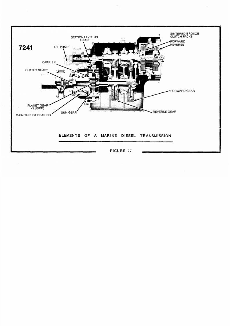
8/18/2019 Marine Propulsion for Small Crafts
http://slidepdf.com/reader/full/marine-propulsion-for-small-crafts 68/71
724
OUTPUT
PLANET GEAR
3 USED)
MAIN THRUST BEARING
STATIONARY RING
SUN
SINTERED BRONZE
CLUTCH PACKS
FORWARD
EVERSE
FORWARD GEAR
REVERSE GEAR
ELEMENTS OF A M RINE
DIESEL
TR NSMISSION
FIGURE 7

8/18/2019 Marine Propulsion for Small Crafts
http://slidepdf.com/reader/full/marine-propulsion-for-small-crafts 69/71
MARINE DRIVE SYSTEMS CONTINUED)
ARNESON DRIVE
A
relative newcomer to
the
marine
propulsion
scene
is
the
Arneson
Drive which combines
a steerable surface
propeller
with a
small rudder
for
low speed operation.
The
configuration of a drive
with
offset
shafts
is
shown in FIGURE TWENTY EIGHT. The
penetration
through the transom is very similar to the sterndrive,
and
the
housing
includes a pair of gears with a strong drive belt,
which
provides a
lower
shaft
speed on the output,
and
also lowers
the
output
shaft
line. A pair of universal joints held within the transom
housing
allow
the shaft assembly to move
up
and down for
trim
and
from
side
to
side for
steering.
The
steering
is
controlled
by a
powerful
hydraulic
cylinder
mounted to the port side, and the elevation is controlled
by
a cylinder mounted above and bolted through the reinforced transom.
Steering is
accomplished
by both the
skeg and
the thrust line
of the propeller. The skeg
provides
a
measure
of
protection
for
the
prop
and
the
upper
blade includes a
spray
shield to cut down
on
the
vertical
spray
thrown off
the prop.
A
highly polished
stainless steel
or
N1-bral prop is used,
and
the best
operation
is normally found with
only the lower half of
the
prop in
the
water. This
is
a surface prop,
and until the Arneson system was
invented,
the
exact
trim to achieve
optimum propulsion was
very
difficult to
achieve.
The propeller
diameter on sterndrives is limited to about
6 inches,
but the
design
of the larger Arneson or KAAMA units permit much larger shaft
diameters, and
the application
of
the system to
large diesels in
the
1000 HP range.

8/18/2019 Marine Propulsion for Small Crafts
http://slidepdf.com/reader/full/marine-propulsion-for-small-crafts 70/71
HYDR ULIC CYLINDER TO
R ISE ND
SPR Y DEFLECTOR
PROPELLER
SKEG FOR PROPELLER PROTECTION
ND
OW
SPEED STEERING
RNESON DRIVE
8

8/18/2019 Marine Propulsion for Small Crafts
http://slidepdf.com/reader/full/marine-propulsion-for-small-crafts 71/71
HYDR ULIC CYLINDER TO
R ISE ND
STEERING CYLINDER
SPR Y DEFLECTOR
SKEG
FOR
PROPELLER PROTECTION
ND
LOW
SPEE STEERING