Embed Size (px)
Citation preview
Mar
ine_
AG
T60
00_1
2-72
V_e
ng.R
0116
.1.0
9
Marine GeneratorPanda PMS AGT 6000
12-72V - 210A / 5,5kW
Fischer Panda
ManualDescription, Installation, Maintenance and Trouble shooting

ii
Current Revision Status
Document
Actual: Marine_AGT6000_12-72V_eng.R01_16.1.09
Replace:
Revision Page
Copyright
Duplication and change of the Datasheet is permitte d only in consultation with the manufacturer!
Fischer Panda GmbH, 33104 Paderborn, reserves all rights regarding text and graphics. Details are given to the bestof our knowledge. No liability is accepted for correctness. Technical modifications for improving the product withoutprevious notice may be undertaken without notice. Before installation, it must be ensured that the pictures, diagramsand related material are applicable to the genset supplied. Enquiries must be made in case of doubt.

Marine_AGT6000_12-72V_eng - Contents - Page 1
ContentsCurrent Revision Status............................ ............................................................................. ii
Safety first ....................................... ........................................................................................ 6
Tools .............................................. .......................................................................................... 7
Safety Precautions ................................. .............................................................................. 10
5 Safety steps to follow if someone is the victim o f electrical shock ............................. 13
WHEN AN ADULT STOPS BREATHING...................... ........................................................ 14
A The Panda Generator............................... .................................................................... 15
A.1 Type plate at the Generator .................... ....................................................................... 15
A.2.1 Right Side View ................................................................................................................. 16
A.2 Description of the Generator ................... ...................................................................... 16
A.2.2 Left Side View ................................................................................................................... 17A.2.3 Front View ......................................................................................................................... 18A.2.4 Back View .......................................................................................................................... 19A.2.5 View from Above ............................................................................................................... 20
A.3 Details of functional units .................... ......................................................................... 21
A.3.1 Components of Cooling System (Raw water) ................................................................... 21A.3.2 Components of Cooling System (Freshwater) .................................................................. 24A.3.3 Components of the Fuel System ....................................................................................... 27A.3.4 Components of Combustion Air ........................................................................................ 30A.3.5 Components of the Electrical System ............................................................................... 33A.3.6 Sensors and Switches for Operating Surveillance ............................................................ 37A.3.7 Components of the Oil Circuit ........................................................................................... 40A.3.8 External Components ........................................................................................................ 41
A.4 Remote Control Panel - see separate Control Pane l Manual ..................................... 41
A.4.1 Starting the Generator - see separate Control Panel Manual ........................................... 41A.4.2 Stopping the Generator - see separate Control Panel Manual ......................................... 41
A Mode of Operation of the Generator ................ .......................................................... 43
A.1 Mode of Operation of Operating Surveillance .... ......................................................... 43
A.1.1 Regulation of the generator voltage by the VCS ............................................................... 46A.1.2 Overloading of engine during longer operation ................................................................. 46A.1.3 Use the failure bypass switch for the fuel delivery ............................................................ 47
A.2 Operation of the generator with HTG generator .. ........................................................ 47
A.2.1 General references ............................................................................................................ 47
A.3 Operation of the generator with automatic start ......................................................... 47
A.4 Operation of the generator with installation und er the waterline .............................. 48
A.5 Operation of the generator with installation ove r the waterline ................................ 49
B Installation Instructions ......................... ..................................................................... 51
B.1 Placement ...................................... ................................................................................. 51
B.1.2 Notice for optimal sound insulation ................................................................................... 51
B.2 Generator Connections - Scheme ................. ............................................................... 52
B.3 Cooling System Installation - Raw water ........ ............................................................. 53

B.3.1 General References .......................................................................................................... 53B.3.2 Installation of the thru-vessel fitting in Yachts ................................................................... 53B.3.3 Quality of the raw water sucking in line ............................................................................. 53B.3.4 Installation above waterline ............................................................................................... 54B.3.5 Installation below waterline ................................................................................................ 55
B.4 The Freshwater - Coolant Circuit ............... ................................................................... 58
B.4.1 Position of the external Cooling Water Expansion Tank ................................................... 58B.4.2 Ventilating at the first filling of the internal cooling water circuit ........................................ 58B.5.1 Installation des Standard-Abgassystems .......................................................................... 62
B.7 Generator 12 V DC System-Installation .......... .............................................................. 69
B.8 Generator DC System-Installation ............... ................................................................. 71
B.10 Insulation test ............................... .................................................................................. 75
B.11 Voltage controller ............................ ............................................................................... 76
B.11.3 Time lag of the switching points ........................................................................................ 76
C Maintenance Instructions .......................... ..................................................................79
C.1 General maintenance instructions ............... ................................................................. 79
C.1.1 Checks before starting ....................................................................................................... 79C.1.2 Hose elements and rubber formed component in the sound cover ................................... 79
C.4 Checking the water separator in the fuel supply ......................................................... 82
C.4.1 Ventilating the fuel system ................................................................................................. 83C.4.2 Exchange of the fuel filter .................................................................................................. 84C.4.3 Exchange the air filter ........................................................................................................ 85C.5.1 Draining the coolant ........................................................................................................... 88
C.6 Exchange of the v-belt for the internal cooling water pump ...................................... 88
C.7 The Raw Water Circuit .......................... ......................................................................... 90
C.7.1 Clean Raw Water Filter ..................................................................................................... 90
C.8 Causes with frequent impeller waste ............ ............................................................... 90
C.8.1 Exchange of the impeller ................................................................................................... 91C.9.1 Measures on preparation of the winter storage ................................................................. 94C.9.2 Initiation at spring .............................................................................................................. 95
D Generator Failure................................. .........................................................................97
D.2 Überlastung des Generators ..................... .................................................................... 97
D.3 Adjusting the Nominal Charge Current ........... ............................................................. 98
D.3.2 Effects of a overload to the actuator .................................................................................. 99
D.5 Prüfen der Generator Stator Wicklungen ......... .......................................................... 102
D.5.1 Testing Generator Stator Winding for "Shorts" to Ground ............................................... 102D.5.2 Coil Resistance Measurements in Stator Windings ......................................................... 103D.5.3 Messung des induktiven Widerstandes ........................................................................... 104
D.6 Starting Problems .............................. ........................................................................... 105
D.6.1 VCS does not work .......................................................................................................... 105D.6.2 Fuel Solenoid Valve and Stop Solenoid .......................................................................... 107
D.7 Troubleshooting Table .......................... ....................................................................... 109
F Tables ............................................ ..............................................................................111
A VCS-AGT-U/I....................................... .........................................................................121
A.1 VCS-AGT-U/I Versions ........................... ...................................................................... 121
A.2 Voltage control system ......................... ....................................................................... 121
A.2.1 Gerneral working of the VCS ........................................................................................... 123

A.2.2 Safety instructions for the voltage control ....................................................................... 123
Generator Control Panel P6+ Manual ................. .............................................................. 125
Current revision status ............................ .......................................................................... 126
A General operation ................................. ..................................................................... 127
A.1 Panel Generator Control ........................ ...................................................................... 127
A.2 Rear view 12V-version .......................... ....................................................................... 128
A.3 Rear view 24V-version .......................... ....................................................................... 129
A.3.1 Terminal connections ...................................................................................................... 130A.3.2 Function of the jumpers ................................................................................................... 131A.3.3 Configuration and adjustment ......................................................................................... 132
A.4 Starting preparation / Checks (daily) .......... ................................................................ 137
A.4.1 Marine version ................................................................................................................. 137A.4.2 Vehicle version ................................................................................................................ 138
A.5 Starting and stopping the generators ........... ............................................................. 138
A.5.1 Starting the generator ...................................................................................................... 138A.5.2 Stopping the generator .................................................................................................... 140
A.6 Automatic adapter - option ..................... ..................................................................... 141
A.6.1 Terminal connections ...................................................................................................... 143
A.7 Master-Slave adapter - option .................. ................................................................... 144
A.7.1 Terminal connections ...................................................................................................... 145A.7.2 Configuration and adjustment ......................................................................................... 146
B Measurements...................................... ...................................................................... 151
B.1 Hole pattern ................................... ............................................................................... 151


5
Fischer Panda
FISCHER GENERATORS have been manufactured since 1978 and are a well-known brand for first class diesel gene-rators with especially effective sound-insulation.
Fischer has been one of the leading manufacturers in respect of quality and know-how during this period.
FISCHER, as the worldwide manufacturer of modern marine diesel generators, developed the Sailor-Silent series forexample and produced a GFK sound-insulated capsule as early as 1979 and the basis for new generator technology.
The companies Fischer and Icemaster amalgamated under the direction of Icemaster in 1988, in order to concentrateon the development of new products. Production was moved to Paderborn.
The amalgamation of the two qualified companies led to the development of a complete new programme within a shortspace of time. The aggregates developed at that time set new technological standards worldwide.
The aggregates became more efficient and powerful than other aggregates in the same nominal performance range,because of the improved cooling. Panda generator demonstrated its superiority in several tests by renowned institutesand magazines during the past years. The patented VCS (voltage Control System) means it can meet all demandsincluding motor speed. The start-booster (ASB) means Panda generators meet the highest demands in respect ofvoltage stability and starting values A Panda generator, with the same drive motor, produces 15% more effective outputthan the majority of conventional generators. This superiority in efficiency also ensures a fuel saving to the same extent.
The 100% water-cooled Panda Aggregate are currently manufactured in the performance range from 2 to 100 kW invarious versions. Fast running motors are preferred for performances up to approx 30 kW (Nominal speed 3000 rpm).The heavier slow runners are preferred for the higher range. The fast running aggregates have proved themselvesmany times for many uses, that they meet the demands in quality of yachts and vehicles, and offer space and weightsaving of 50% compared to slow running generators.
In addition to the Panda series, Fischer Panda also supply the super compact high-tech sound-insulated battery char-ging aggregate from the DC/AC Panda AGT series, which is a very interesting solution for the production of mobilepower.
The new HTG-alternators ensure that a charging rate of 285 amps is achieved that was scarcely thought possible forthis compact construction. This alternator replaces a separate shipboard generators (constant 230 volts AC with up to3500 kW from the main machine)
Fischer Panda GmbH, 33104 Paderborn, reserves all rights regarding text and graphics. Details are given to the best of our knowledge. No liability is accepted for correct-ness. Technical modifications for improving the product without previous notice may be undertaken without notice. Before installation, it must be ensured that the Pictures,diagrams and related material are applicable to the aggregate supplied. Enquiries must be made in case o doubt.
Icemaster GmbH Fischer MarineGenerators
Conclusion Fischer - Icemaster GmbH
100 % water cooled Pan-da generators
Panda Vehicle Genera-tors
since 1977
since 1978
since 1988
since 1988
since 1988

6
Safety first
These symbols are used throughout this manual and on labels on the maschine itself to warn of the possibility of per-sonal injutry. Read these instructions carefully. It is essential that you read the instructions and safety regulationsbefore you attempt to assemble or use unit.
This danger symbol refers to toxic danger and draws attention to special warnings,instructions or procedures which, if not strictly observed, may result in severe per-sonal injury or loss of life.
This danger symbol refers to electric danger and draws attention to specialwarnings, instructions or procedures which, if not strictly observed, may result inelectrical shock which will result in severe personal injury or loss of life.
This danger symbol refers to electric danger and draws attention to specialwarnings, instructions or procedures which, if not strictly observed, may result inelectrical shock which will result in severe personal injury or loss of life.
This warning symbol draws attention to special warnings, instructions or procedureswhich, if not strictly observed, may result in damage or destruction of equipment,severe personal injury or loss of life.
This warning symbol draws attention to special warnings, instructions or procedureswhich, if not strictly observed, may result in damage or destruction of equipment

7
Tools
This symbols are used throughout this manual to show which tool must be used at maintenance or installation.
Spanners
X = number of spanner
Hook wrench for oil filter
Screw driver, for slotted head screws and for recessed head screws
Multimeter, multimeter with capacitor measuring
Infrared temperature mesuring pistol
Current clamp (DC for synchron generators; AC for asynchron generators)
X

8
Socket wrench set
Hexagon wrench keys

9
CALIFORNIA
Proposition 65 Warning
Diesel engine exhaust and some of its constituents are known to the State of California to cause cance r,
birth defects, and other reproductive harm.
Attention, Important Directions regarding Operation !
1. The installation certificate must be completed when taken into use, and certified by a signature.
2. The installation certificate must be despatched within two weeks of use to Fischer Panda.
3. The official guaranty confirmation will be completed by Fischer Panda after receipt and sent to the customer.
4. A guaranty must be shown to make any claims.
Claims against the guaranty will not be accepted of the above said instructions are not, or only partially, carried out.
Manufacturer declaration in terms of the machine gu ideline 98/37/EG .
The generator is in such a way developed that all assembly groups correspond to the CE guidelines. If machine gui-deline 98/37/EG is applicable, then it is forbidden to bring the generator into operation until it has been determinedthat the system into which the generator is to be installed in also corresponds to the regulations of the machine gui-deline 98/37/EG. This concerns among other things the exhaust system, cooling system and the electrical installa-tion.
The evaluation of the "protection against contact" can only be accomplished in connection with the respectivesystem. Likewise among other things responsibility for correct electrical connections, a safe ground wire connection,foreign body and humidity protection, protection against humidity due to excessive condensation as well as the over-heating through appropriate and inappropriate use in its installed state on the respective machine lies within theresponsibility of those who undertake installation of the generator in the system.
Use the advantages of the customer registration:
• Thus you receive to extended product informations, which are sometimes safety-relevant
• you receive, if necessarily free Upgrades
Far advantages:
By your full information Fischer Panda technicians can give you fast assistance, since 90% of the disturbances resultfrom errors in the periphery.
Problems due to errors in the installation can be recognized in the apron.
Technical Support per Internet: [email protected]

10
Safety Precautions
The electrical Installations may only be carried ou t be trained and
tested personnel!
The generator may not be taken into use with the co ver removed.
The rotating parts (belt-pulley, belts, etc) must be so covered and protected do that there is no danger to life andbody!If a sound insulation covering must be produced at the place of installation, then well-placed signs must show thatthe generator can only be switched on with a closed capsule.All servicing-, maintenance or repair work may only carried out, when the motor is not running.
Electrical voltages above 48 volts ( battery chargers greater than 36 volts) are always dangerous to life). The rules ofthe respective regional authority must be adhered to. Only an electrician may carry out installation of the electricalconnections for safety reasons.
General safety references for the enterprise of a A GT generator.
With all energized systems, with which the current is more than 50 Ampère, special safety precautions must bemade, in order to protect the environment of the components against fire.
It is to be ensured absolutely that at the battery a main switch in well accessible place is accommodated, so that withdanger of the main switches can be separated immediately. The main switch must be however also directly at thebattery installed. If this place is not well accessible, a power relay must be used instead of the main switch which canbe served manually, which can be served then if necessary from different places. The switches for the power relayare to mark accordingly as main switches DC battery "with danger switch off!".
Cooling of the rectifier block at the marine versio ns
The retifier block is cooled with fresh water. A normal cooling of the rectifier block is therefore only possible, as longas the cooling water supply of the generator functions duly. The cooling water supply of the generator must be so fur-nished therefore that by a wide dirt deflector it is guaranteed that from outside no dirt can be sucked in into the linesystem. If this is not attainable, the supply must be secured by a flow switch or a negative pressure switch. The gene-rator must be switched off, if the cooling water supply is impair.
The temperature safety device on the rectifier block can be regarded only as additional safety device. The tempera-ture rise at the diods is so fast that the rectifiers can be damaged during a unique interruption of the cooling watersupply. A safe protection from damage of the rectifiers is not possible by the temperature monitoring on the rectifierradiator box. Thus this can take place only by means of an appropriate external monitoring of the cooling system.
ATTENTION!
Do not connect the minus pole of the starter batter y to the ground of the boat because of galvanic rea son.
Warning!
Never start the generator with the battery disconne cted, the rectifiers will be damaged!
CAUTION!
Contact of the electrical contacts may be DANGER TO LIVE!

11
CAUTION!
The AGT-generator is not allowed to be connected to an inverter (without batteries)!
The Inverter generates voltage peaks, which can des troy the rectifier rectifiers of the generator!
A battery must always be connected to the inverter as a capacity!
Recommended capacity at 12V ≥ 240Ah at 24V ≥ 120Ah
The screws at the electric rectifier may be pulled tight only with a torque wrench. Torque 6 Nm.
The battery cable must be secured at the generator and at the batteries with appropriate safety device s.
The generator is also include into the CO 2 - fire-extinguishing system.

12
Measures to the fire protection.
All construction units in the environment of energized parts, which carry more than 50 Amp., must be fire protection-moderately secured.
All junction points at the energized parts must be examined regularly on heating up (infrared thermometers).
Safety Instrictions for the Handling with Batteries
These instructions must be noticed additionally to the instructions of the battery manufacturer:
• If the batteries are working, someone should be in your near area to help you in a case of emergency.
• Water and soap must be hold ready if battery acid corrode your skin.
• Wear eye protection and protective clothing. During working with the batteries don´t touch the eyes.
• If you got a acid splash on your skin or clothing grow it with much water and soap out.
• If you got acid in your eyes rinse them immediately with clear water until no cauterization is noticeable. Visit imme-diate a doctor.
• Don´t smoke in the near of the batteries. Avoid naked flames or open fires. In the area of batteries exists danger of explosions.
• Pay attention that no tools fall on the battery poles, if necessary cover them.
• During the installation don´t wear a wrist watch or arm jewels, you can create under these circumstances a battery short-circuit. Burning of the skin could be the result.
• Protect every battery contact against unintentional touch.
• Use only cyclical profoundly dischargeable batteries. Starter batteries are not appropriate. Lead-gel batteries are commended. They are maintenance-free, profoundly dischargeable and not produce gas.
• Do not charge a frozen battery.
• Avoid a batterie short-curcuit.
• Take care of a good ventilation of the battery to drain off developing gas.
• The battery connection terminals must be checked of a tight contact at least before operating.
• The battery connection cable must be carefully mounted and checked about incorrect heating at operation with load. The vibrating devices must be regulary checked about scour points and flaw in the isolation.
13
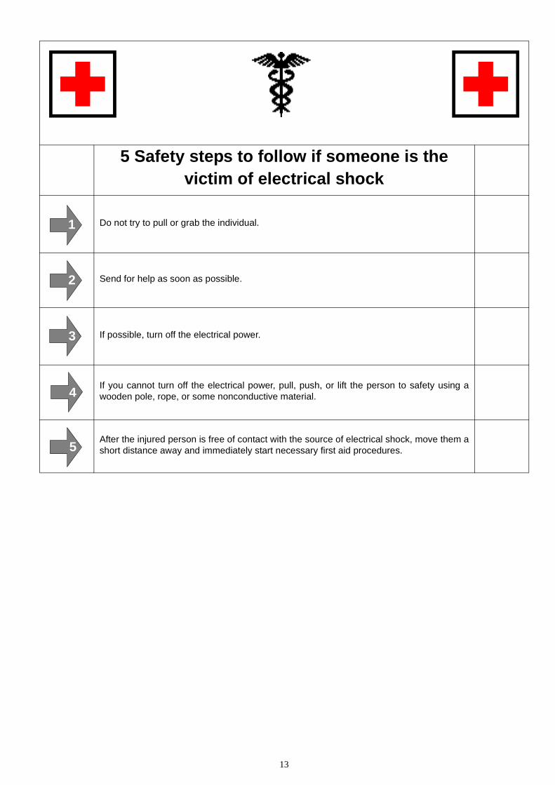
5 Safety steps to follow if someone is the victim of electrical shock
Do not try to pull or grab the individual.
Send for help as soon as possible.
If possible, turn off the electrical power.
If you cannot turn off the electrical power, pull, push, or lift the person to safety using awooden pole, rope, or some nonconductive material.
After the injured person is free of contact with the source of electrical shock, move them ashort distance away and immediately start necessary first aid procedures.
1
1
1
2
1
3
1
4
1
5

14
WHEN AN ADULT STOPS BREATHING
WARNING
DO NOT attempt to perform the rescue breathing tech niques provided on this page, unlesscertified. Performance of these techniques by uncer tified personnel could result in furtherinjury or death to the victim.
1 Does the Person Respond? 2 Shout, "Help!"
Tap or gently shake victim.
Shout, "Are you OK?"
Call people who can phone for help.
3 Roll Person onto Back.
Roll victim toward you by pulling slowly.
4 Open Airway. 5 Check for Breathing.
Tilt head back, and lift chin.
Shout, "Are you OK?"
Look, listen, and feel for breathingfor 3 to 5 seconds.
6 Give 2 Full Breaths.
Keep head tilted back.
Pinch nose shut.
Seal your lips tight around victim'smouth.
Give 2 full breaths for 1 to 1½ secondseach.
7 Check for Pulse at side of Neck. 8 Phone EMS for Help.
Feel for pulse for 5 to 10 seconds. Send someone to call an ambu-lance.
9 Begin Rescue Breathing. 10 Recheck Pulse Every Minute.
Keep head tilted back.
Lift chin.
Pinch nose shut.
Give 1 full breath every 5 seconds.
Look, listen, and feel for breathing bet-ween breaths.
Keep head tilted back.
Feel for pulse for 5 to 10 seconds.
If victim has pulse, not breathing,continue rescue breathing. If nopulse, begin CPR.
The Panda Generator
16.1.09 Marine_AGT6000_12-72V_eng - Kapitel A: The Panda Generator Seite 15
A.The Panda Generator
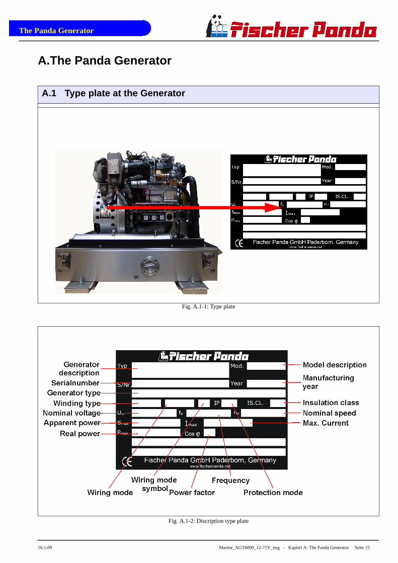
A.1 Type plate at the Generator
Fig. A.1-1: Type plate
Fig. A.1-2: Discription type plate

The Panda Generator
Seite 16 Marine_AGT6000_12-72V_eng - Kapitel A: The Panda Generator 16.1.09
A.2 Description of the Generator
A.2.1 Right Side View
Fig. A.2.1-1: Right Side View
08
01
02
03
05
06
04 09
13
17
18
07 19
11 12
20
10 14 15 16
01) DC-alternator 12V02) V-belt für DC-alternator and cooling water pump03) Oil pressure switch04) Oil filter05) Diode block under protection cover06) Sound cover base part07) Water-cooled exhaust elbow08) Solenoid for starter motor09) Starter motor
10) Cooling water return pipe11) Thermo-switch exhaust12) Exhaust connection port13) Exhaust output14) Stop-cock (optional)15) Connection external ventilation valve16) In-flow from external cooling water expansion tank17) Return external cooling water expansion tank18) Injection port raw water

The Panda Generator
16.1.09 Marine_AGT6000_12-72V_eng - Kapitel A: The Panda Generator Seite 17
A.2.2 Left Side View
Fig. A.2.2-1: Left Side View
01
05
24
23
22
21
20
19
18
11
12 13 14 17
02
03
04
06 07 08 15 16
09
10
01) Air suction housing with air filter02) Charge control for DC-alternator03) Air suction port for coil cooling (GFK sound cover only)04) Time relay for stop solenoid05) Connection for external ventilation valve06) Sound cover base part07) Generator housing with coil08) Heat exchanger09) Electric starter control unit10) Suction hose, air suction housing - induction elbow11) Actuator for rpm-regulation12) Electrical fuses (blue=15A, white=25A)
13) Starter-relay Ks14) Pre-glow relay (glow plugs) K215) Fuel pump start relay K316) Failure bypass switch17) Raw water intake18) Oil dipstick19) Raw water intake hose20) Fuel filter21) Fuel solenoid valve22) Stop solenoid23) Ventilation screw cooling water pump24) Ventilation screw thermostat housing

The Panda Generator
Seite 18 Marine_AGT6000_12-72V_eng - Kapitel A: The Panda Generator 16.1.09
A.2.3 Front View
Fig. A.2.3-1: Front View
01
26
23
08 17 1809 10 11 12 13 1614 15
0203
05
24
2206
07
04
20
19
25
21
01) Ventilation screw internal cooling water pump02) Stop solenoid03) Pulley for internal cooling water pump04) Fuel filter05) Raw water pump06) Raw water intake hose07) Sound cover base part08) Raw water intake09) Connection fuel in10) Connection fuel out11) Cable fuel pump (2x1,5mm²)12) Oil drain hose13) Cable remote control panel (12x1mm²)
14) Cable voltage control VCS (5x1mm²)15) Voltage sense 24 V16) Shunt measurement17) Starter battery minus (-)18) Starter battery plus (+)19) Passage for service battery cable20) Passage for service battery cable21) Diode block22) Oil filter23) V-belt24) DC-alternator 12 V25) Clamp device for DC-alternator26) Ventilation screw thermotast housing

The Panda Generator
16.1.09 Marine_AGT6000_12-72V_eng - Kapitel A: The Panda Generator Seite 19
A.2.4 Back View
Fig. A.2.4-1: Back View
01
03 04
10 1109
02
07
08
06
05
12
13
14
15
01) Cooling water filler neck02) Water-cooled exhaust elbow02) Thermo-switch exhaust elbow04) Air suction housing with air filter05) Bypass for generator housing cooling 06) Injection port raw water07) Stop-cock (optional)08) Generator front cover
09) In-flow from external cooling water expansion tank10) Return to external cooling water expansion tank11) Connection external ventilation valve12) Heat exchanger13) Suction port for coil cooling (GFK sound cover only)14) Electric starter control unit15) Charge control for DC-alternator

The Panda Generator
Seite 20 Marine_AGT6000_12-72V_eng.R01 - Kapitel A: The Panda Generator 16.1.09
A.2.5 View from Above
Fig. A.2.5-1: View from Above
18
03
14
15
13
12
06 07 08
17
01
16
02
04
05
09 10 11
01) Thermo-switch exhaust elbow02) Ventilation hose to external expansion tank03) Air suction housing with air filter04) Suction port for coil cooling05) Charge control for DC-alternator06) Eletctric starter control unit07) Thermo-switch cylinder head08) Suction hose, air suction housing - induction elbow09) Fuel solenoid valve
10) Thermostat housing with thermostat11) Stop solenoid12) Ventilation screw internal cooling water pump13) Oil filler neck14) Ventilation screw thermostat housing15) Thermostat housing16) DC-alternator17) Water-cooled exhaust elbow18) Cooling water filler neck

The Panda Generator
16.1.09 Marine_AGT6000_12-72V_eng.R01 - Kapitel A: The Panda Generator Seite 21
A.3 Details of functional units
A.3.1 Components of Cooling System (Raw water)
Raw water intake
The diagram shows the supply pipes for thegenerator. The connection neck for the seawa-ter connection is shown on the left hand side.The cross-section of the intake pipe should benominally larger than the generator connec-tion.
Fig. A.3.1-1: Raw Water Intake
Raw Water Impeller Pump
The raw water pump is fitted with a rubberimpeller. This pump is self-inductive. If,for example, you forget to open the seavalve, then you must expect the impellerto be destroyed after a short period oftime. It is recommended to store severalimpellers on board as spare parts.
Fig. A.3.1-2: Raw Water Impeller Pump

The Panda Generator
Seite 22 Marine_AGT6000_12-72V_eng.R01 - Kapitel A: The Panda Generator 16.1.09
Heat Exchanger
Separates the raw water system from thefresh water system, so that the generatorcomponents do not have contact with theraw water circulation system. The rawwater is fed direct to the exhaust connec-tion piece at the heat exchanger outlet.
Fig. A.3.1-3: Heat Exchanger
Ventilation valve
A siphon must be installed if the genera-tor sinks below the water line because ofthe rocking of the boat, even if it is onlyfor a short period of time. A hose pipe onthe generator casing has been producedfor this. Both connecting pieces arebridged by a formed piece of hose.
Fig. A.3.1-4: Connection for Ventilation Valve
Stop-cock
The raw water is injected into the exhaust con-nection (A). Also raw water is leading to thediode block (B).
Adjust with the stop-cock an inpression thatraw water is lead to the diode block.
ATTENTION: The stop-cock may neverbe completely opened or closed, sinceotherwise the diode block or exhaustconnection can become too hot.
Fig. A.3.1-5: Stop-Cock
A
B

The Panda Generator
16.1.09 Marine_AGT6000_12-72V_eng.R01 - Kapitel A: The Panda Generator Seite 23
Raw water hose
After the raw water has passed the diodeblock it is lead to the generator housing
Fig. A.3.1-6: Raw Water Hose
IN/OUT generator housing
The raw water cooles the coil in the generator housing.
Fig. A.3.1-7: In/Out Generator Housing
Cooling water injector nozzle
The injection point for the marine generatorwater-cooled exhaust system is located at theexhaust connection pieces. The exhaust con-nections must be regularly checked for signs ofcorrosion.
Fig. A.3.1-8: Injetion Nozzles for Cooling Water

The Panda Generator
Seite 24 Marine_AGT6000_12-72V_eng.R01 - Kapitel A: The Panda Generator 16.1.09
A.3.2 Components of Cooling System (Freshwater)
Filler neck
The cooling water filler necks situated at thewater-cooled manifold are only used, when thegenerator is initially started. Since the genera-tor is normally already filled with cooling water,these components are only by the user, ifrepairs are to be carried out. Topping up withcooling water may only carried out at the exter-nal cooling water compensation tank. Note thatthe water level in the cooling water compensa-tion tank is only 20 % of the volume in a coldstate.
Fig. A.3.2-1: Cooling Water Filler Neck
Freshwater backflow
The cooling water leads from the water-cooledmanifold to the heat exchanger by means ofthe pipe shown in the diagram.
Fig. A.3.2-2: Freshwater Backflow
Ventilation pipe
The ventilation pipe at the water-cooledexhaust manifold leads to the external expan-sion tank. This pipe only serves as a ventilationpipe, if both pipes are to be connected to theexternal expansion tank (ventilation pipe andintake pipe).
Fig. A.3.2-3: Ventilation Pipe

The Panda Generator
16.1.09 Marine_AGT6000_12-72V_eng.R01 - Kapitel A: The Panda Generator Seite 25
Hose connection pieces for the external expansion tank
The external expansion tank is connected bytwo hose connections. The connecting piecesshowed here serves as constant ventilation forthe water-cooling system.
In case the external expansion tank is connec-ted with two hoses, the system will ventilateitself. In this case, additional ventilation is onlynecessary when the generator is initially filled,or if the cooling water is not circulating.
Fig. A.3.2-4: External Expansion Tank
Heat exchanger
The internal freshwater circulation system isseparated from the Raw water circulationsystem by the heat exchanger. This means theRaw water circulation system does not comeinto contact with the generator components.The Raw water is fed directly to the exhaustconnection at the heat exchanger outlet.
Fig. A.3.2-5: Heat Exchanger
Cooling water intake
A.) To the thermostat housing
B.) From the external expansion tank
The intake pipe from the external cooling waterexpansion tank is connected to the pointshown with „B“.
Fig. A.3.2-6: Cooling Water Intake
A
B

The Panda Generator
Seite 26 Marine_AGT6000_12-72V_eng.R01 - Kapitel A: The Panda Generator 16.1.09
Internal cooling water pump
The diesel motor cooling water pump (seearrow) aids the circulation of the internal fres-hwater system.
Fig. A.3.2-7: Internal Cooling Water Pump
Internal cooling water pump
The diesel motor cooling water pump (seearrow) aids the circulation of the internal fres-hwater system.
Fig. A.3.2-8: Internal Cooling Water Pump
Ventilation screw thermostat housing
The ventilation screw on the thermostat hou-sing should occasionally be opened for controlpurposes. Standing machinery should princi-pally carry out ventilating.
Fig. A.3.2-9: Ventilation Screw Thermostat Housing

The Panda Generator
16.1.09 Marine_AGT6000_12-72V_eng.R01 - Kapitel A: The Panda Generator Seite 27
Water-cooled exhaust manifold
The manifold is cooled by means of the internalcooling system (freshwater). The cooling waterfiller necks on the casing of the manifold maynot be opened. These cooling water necks areonly required to fill the motor with cooling waterin cases of repair. The normal cooling watercontrols may only be carried out at the externalexpansion tank.
Fig. A.3.2-10: Water-Cooled Exhaust Manifold
A.3.3 Components of the Fuel System
External fuel pump
The Panda generator is always supplied with anexternal, electrical (12 V DC) fuel pump. Thefuel pump must be always installed in the proxi-mity of the tank. The electrical connections withthe lead planned for it are before installed at thegenerator. Since the suction height and the sup-ply pressure are limited, it can be sometimespossible that for reinforcement a second pumpmust be installed.
Fig. A.3.3-1: External Fuel Pump
Connecting Pieces for the Fuel Pipe
1. Fuel intake
2. Fuel backflow
Fig. A.3.3-2: Connection Pieces for the Fuel Pipe
1 2

The Panda Generator
Seite 28 Marine_AGT6000_12-72V_eng.R01 - Kapitel A: The Panda Generator 16.1.09
Fuel Filter
A consequential filtering of fuel is especi-ally important for all marine systems. A finefilter, which is firmly attached to the insideof the sound insulation capsule for themarine version, is supplied on delivery, andloose for other makes. In all cases a furtherpre-filter with water separator must beinstalled. See directions for fuel filter instal-lation.
Fig. A.3.3-3: Fuel Filter
Fuel Solenoid Valve
The fuel solenoid valve opens automatically if "START" is pressed on the remote control panel". The solenoid closes, if the generator is switched to "OFF"position. It takes a few seconds before the generator stops. If the generator does not start or does not run smoothly (i.e. stutters), or does not attain full speed, then the cause is fore-mostly the solenoid.
Fig. A.3.3-4: Fuel Solenoid Valve
Injection Nozzle
If the engine does not start after the venti-lation, the fuel injection lines must be ven-tilated individually.
Fig. A.3.3-5: Injection Nozzles

The Panda Generator
16.1.09 Marine_AGT6000_12-72V_eng.R01 - Kapitel A: The Panda Generator Seite 29
Glow Plugs
The glow plugs serve the pre-chamber for theheating with cold start. The glow device mustbe operated, if the temperature of the genera-tor is below 16 ° C. This is practically the casewith each start. The glow device and starterbutton are set so that neither may be used atthe same time.
Fig. A.3.3-6: Glow Plugs
Stop Solenoid for Engine Stop
Some models are additional equipped with astop solenoid. The generator is stopped by theco-operation of the stop solenoid immediatelyafter switching off. The adjustment of the stopsolenoid must always be checked, in order tobe sure that the stop lever operate freely and isnot placed under pre-stress.
Fig. A.3.3-7: Stop Solenoid for Engine Stop

The Panda Generator
Seite 30 Marine_AGT6000_12-72V_eng.R01 - Kapitel A: The Panda Generator 16.1.09
A.3.4 Components of Combustion Air
Air suction openings at the sound cover
The sound cover is provided at the upper sur-face with drillings, through which the combu-stion air can influx.
It must be consistently paid attention that thegenerator is installed in such a way that fromno water can arrive into the proximity of theseair openings. (minimum distance 150 mm)
Fig. A.3.4-1: Combustion Air Intake
Cooling air for coil cooling
The sound cover upper surface is provided atback side with drillings, through which the coo-ling air can influx.
It must be consistently paid attention that thegenerator is installed in such a way that fromno water can arrive into the proximity of theseair openings.
Fig. A.3.4-2: Freshwater Intake
Air suction housing
Remove the cover to look indes the hou-sing. There is a filter element. This mustbe checked from timt to time.
Fig. A.3.4-3: Air Suction Housing

The Panda Generator
16.1.09 Marine_AGT6000_12-72V_eng.R01 - Kapitel A: The Panda Generator Seite 31
Air suction housing with air filter set
If the capsule is removed, the inside of the airsuction housing becomes visible. In these airsuction housings is a filter element. At themarine version the filter is normally not chan-ged. It should be chekked once in a while.
Fig. A.3.4-4: Air Filter Set
Combustion chamber intake elbow
The figure shows the induction elbow at thecombustion engine. At the front of this induc-tion elbow you can see the hose connectionbetween air suction housings and inductionelbow. The air filter must be checked, if thishose contracts during operation.
Fig. A.3.4-5: Combustion Chamber Intake Elbow
Exhaust elbow
At the back side of the engine is the water-coo-led exhaust elbow.
Underneath the exhaust elbow, the raw wateris injected into the exhaust
On the top side, the pipe union for the internalraw water circuit is to be seen and the fillerneck for the cooling water.
Fig. A.3.4-6: Exhaust Elbow

The Panda Generator
Seite 32 Marine_AGT6000_12-72V_eng.R01 - Kapitel A: The Panda Generator 16.1.09
Exhaust connection at the exhaust elbow
Raw water from the external cooling circle is fed here.
Fig. A.3.4-7: Exhaust Connection
Exhaust outlet
Connect the exhaust pipe with the water lock.
Fig. A.3.4-8: Exhaust Outlet

The Panda Generator
16.1.09 Marine_AGT6000_12-72V_eng.R01 - Kapitel A: The Panda Generator Seite 33
A.3.5 Components of the Electrical System
Connection starter battery
1. Cable for starter battery (plus)
2. Cable for starter battery (minus)
During connection to the starter battery, it must be always ensured that the contact is guaran-teed.
Fig. A.3.5-1: Connection Starter Battery
Main power
At the front of the sound insulation cover isalso the outlet for the main power cable. Hereare also the cables for external condensersconnections, depending upon type of genera-tor (see Connection Diagram for the AC-Con-trol box!)
Fig. A.3.5-2: Main Power
Electrical connections for control
All remaining cables are located at the frontend of the generator for electrical connections,depending upon type. The connections aretaken from the AC-Control Box Plan. Seehere:
1. Fuel pump
2. Remote control panel
3. VCS
4. AC-Control-Box
Fig. A.3.5-3: Electrical Connections
12
431 2 5

The Panda Generator
Seite 34 Marine_AGT6000_12-72V_eng.R01 - Kapitel A: The Panda Generator 16.1.09
Starter motor
1. Starter motor and
2. Solenoid switch
The diesel engine is started electrically. Theelectrical starter with the solenoid switch islocated at the rear of the engine.
Fig. A.3.5-4: Starter Motor
Actuator for speed regulation
The generator voltage is determined by pro-gressive speed control through "VCS" in con-junction with the speed actuator. Speedincreases with increasing load.
Fig. A.3.5-5: Actuator
Plug for speed sensor
All Panda generators can be equipped with anexternal automatic start. For the operation ofthis automatic starting system a separatespeed sensor is necessary. At some modelsthe speed sensor is standard installed.
Fig. A.3.5-6: Plug for Speed Sensor
1
2

The Panda Generator
16.1.09 Marine_AGT6000_12-72V_eng.R01 - Kapitel A: The Panda Generator Seite 35
DC-alternator
All Panda generators from Panda 6.000are provided with its own charge systemfor the 12V DC mains. This DC-alternatoris powered over a v-belt together with theinternal cooling water pump.
The 12 V charge system may be used only forthe generator-own starter battery.
Fig. A.3.5-7: Lichtmaschine
Charge control for DC-alternator
The voltage regulator for the 12 V DC-alterna-tor is located at the back of the air suction hou-sing. The housing is streamlined for coolingpurposes. The voltage regulator may not beexternally covered. The surface must beaccessible for cooling.
Fig. A.3.5-8: Charge Control
Restart Protection
If there is an automatic starting require-ment and the remote control panel is swit-ched off, then this automatic startingrequirement will be ignored. Automaticstarting is only possible after switching onthe remote control panel.
Fig. A.1: Restart Protection

The Panda Generator
Seite 36 Marine_AGT6000_12-72V_eng.R01 - Kapitel A: The Panda Generator 16.1.09
Time relay for stop solenoid
Fig. A.3.5-9: Time Relay for Stop Solenoid
Diode plate
Fig. A.3.5-10: Diode plate
Fuse for measurement voltage
Fig. A.3.5-11: Fuse for Measurement Voltage

The Panda Generator
16.1.09 Marine_AGT6000_12-72V_eng.R01 - Kapitel A: The Panda Generator Seite 37
Terminal block for remote control cable with fuses and power relais
F1 fuse 15 A for DC wiring
F2 fuse 25 A for starter relay
Ks power relais for Starter
K2 power relais for Glow plugs
K3 power relais for Fuel pump
Fig. A.3.5-12: Terminal block
A.3.6 Sensors and Switches for Operating Surveillanc e
Thermo-switch at cylinder head
The thermo-switch at the cylinder head servesto monitor the generator temperature. Allthermo-switches for the generators fromPanda 6.000 upward are two-pole (earthed),so called "openers". This means the contactsare open in normal cases and close only whenthe limits have been exceeded.
Fig. A.3.6-1: Thermo-switch at Cylinder Head
Thermo-switch at watercooled exhaust elbow
This thermo switch is located at the water-cooled exhaust elbow and serves to moni-tor the freshwater circulation system. Ittakes a measurement at the warmestspot, since the combustion gases are gui-ded from the cylinder head to the exhaustelbow.
Fig. A.3.6-2: Thermo-switch at Watercooled Exhaust Elbow
K2Ks K3
F1 F2

The Panda Generator
Seite 38 Marine_AGT6000_12-72V_eng.R01 - Kapitel A: The Panda Generator 16.1.09
Thermo-switch at exhaust connection
If the impeller pump stops and delivers no more seawater, the exhaust connection beco-mes extremely hot. The thermo-switch controls the raw water circuit.
Fig. A.3.6-3: Thermo-switch at Exhaust Connection
Thermo-switch in the Generator Winding
1. Generator winding
2. Thermo-switch
3. Housing
Two thermo-switches inside the windings to protect the generator winding, which for safety reasons are installed independently in parallel.
Fig. A.3.6-4: Thermo-switch in the Generator Winding
Thermo-switch on the (-)-bar
(-)-bar at the diode block
Fig. A.3.6-5: Thermo-switch on the (-)-bar
1
3
2

The Panda Generator
16.1.09 Marine_AGT6000_12-72V_eng.R01 - Kapitel A: The Panda Generator Seite 39
Thermo-switch on the (+)-bar
(+)-bar at the diode block
Fig. A.3.6-6: Themo-switch at the (+)-bar
Oil pressure switch at the diesel engine
In order to be able to monitor the lubrica-ting oil system, an oil pressure switch isbuilt into the system. The oil pressureswitch is at the rear of the engine (In frontof the electrical starter).
Fig. A.3.6-7: Oil pressure switch
Failure Bypass Switch
The failure bypass switch offers the possi-bility of starting the generator if the electri-cal control switches off due to overheatingof the cooling system.
Fig. A.3.6-8: Failure Bypass Switch

The Panda Generator
Seite 40 Marine_AGT6000_12-72V_eng.R01 - Kapitel A: The Panda Generator 16.1.09
A.3.7 Components of the Oil Circuit
Oil filler neck with cap
Normally the filler neck for the engine oilis on the top side of the valve cover. Asecond filler neck is additionally attachedat the operating side for numerous gene-rator types. Please ensure the filler necksare always well secured after filling withengine oil.
Consider also the references to the engine oil specification.
Fig. A.3.7-1: Oil Filler Neck with Cap
Oil dipstick
At the dipstick the permissible level is indicatedby the markings "maximum" and "minimum".The engine oil should be never filled beyondthe maximum.
Fig. A.3.7-2: Oil Dipstick
Oil filter
The oil filter should also be replaced, when anoil change is carried out.
Fig. A.3.7-3: Oil Filter

The Panda Generator
16.1.09 Marine_AGT6000_12-72V_eng.R01 - Kapitel A: The Panda Generator Seite 41
Oil drain hose
The Panda generator is equipped so thatthe engine oil can be drained by means ofa hose. The generator should be installedin such a way, that a collecting basin canbe placed deeply enough. If this is notpossible, an electrical oil drain pump mustbe installed.
Note : Lubricating oil should be drained warm!
Fig. A.3.7-4: Oil Drain Hose
A.3.8 External Components
Voltage control VCS
The diagram shows the control circuit board forthe VCS. The control signals are passed to theactuator for speed regulation by means of thiscircuit control board. The VCS board allows forvoltage adjustment.
Fig. A.3.8-1: VCS
Battey Monitor
Fig. A.3.8-2: Battery Monitor

The Panda Generator
Seite 42 Marine_AGT6000_12-72V_eng - Kapitel A: The Panda Generator 16.1.09

Mode of Operation of the Generator
16.1.09 Marine_AGT6000_12-72V_eng.R01 - Kapitel A: Mode of Operation of the Generator Seite 43
A. Mode of Operation of the Generator
A.1 Mode of Operation of Operating Surveillance
Internal monitoring switches
The generator is equipped about failure switches, which are indicated on the remote controlpanel, and also about failure switch, which switch-off the generator automatically without indica-ting a failure in the remote control panel:
The remote control panel supervised the following values. In the case of a disturbance the gene-rator is switched off, in order to avoid damage to the genset:
1. Cooling water temperature at cylinder head, at exhaust manifold and exhaust connection
2. Coil temperature
3. Diode block temperature
4. Oil pressure
The fault is transmitted, if one of these switches measures a value that exceeds the requiredvalue (all switches are openers). The current is switched off by the main relay. (Fuel magnet valvecloses, the fuel suction pump is switched off, VCS is switched off).
The combustion engine possesses an oil pressure control switch, which switches the engine off ifthe oil pressure drops under a certain value.
The additional failure switch in the generator coil, it is not indicated at the remote control panel,interrupts directly the current supply to the main power relay. By this constellation it is guaranteedthat the generator switches off in each case when an error is present.
This measure is, if possibly, a circuit at the remote control panel failed.
Thermo-switch at cylinder head
The thermo-switch at the cylinder headserves the monitoring of the generatortemperature. All thermo-switches for thegenerators from Panda 6.000 upward aretwo-pole and laidout as "openers".
Fig. A.1-1: Thermo-switch at cylinder head

Mode of Operation of the Generator
Seite 44 Marine_AGT6000_12-72V_eng.R01 - Kapitel A: Mode of Operation of the Generator 16.1.09
Thermo-switch at watercooled exhaust elbow
This thermo-swich is located at the water-cooled exhaust elbow and monitors thetemperature of the fresh water circuit. Theswitch measures at the hottest place,because the flue gases lead from thecylinder head into the exhaust elbow.
Fig. A.1-2: Thermo-switch at exhaust elbow
Thermo-switch at exhaust connection
If the impeller pump drop out and delive-res no more raw water, the exhaust con-nection becomes extremely hot.
Fig. A.1-3: Thermo-switch at exhaust connection
Thermo-switch in the generator coil
1. Generator coil
2. Thermo-switch
3. Housing
For the protection of the generator coilthere are two thermo-switches inside thecoil, which are for inserted parallel andsafety's sake independently from eachother.
Fig. A.1-4: Thermo-switch coil
1
3
2
Mode of Operation of the Generator
16.1.09 Marine_AGT6000_12-72V_eng.R01 - Kapitel A: Mode of Operation of the Generator Seite 45
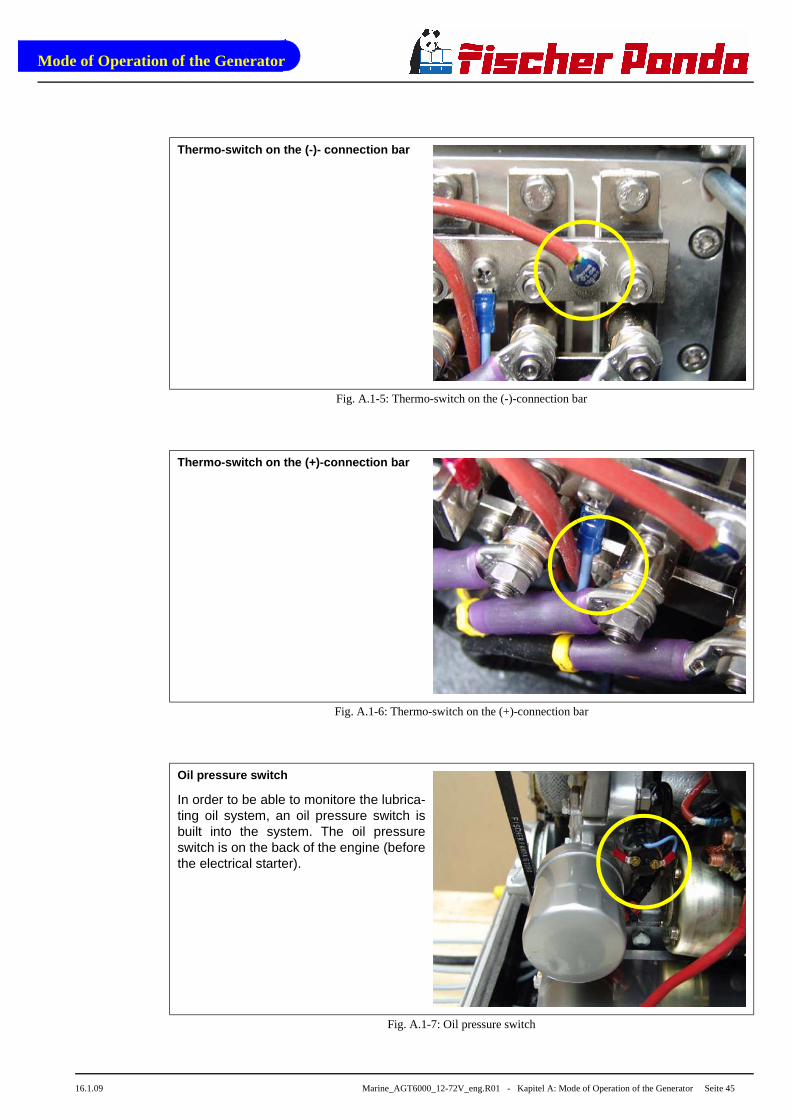
Thermo-switch on the (-)- connection bar
Fig. A.1-5: Thermo-switch on the (-)-connection bar
Thermo-switch on the (+)-connection bar
Fig. A.1-6: Thermo-switch on the (+)-connection bar
Oil pressure switch
In order to be able to monitore the lubrica-ting oil system, an oil pressure switch isbuilt into the system. The oil pressureswitch is on the back of the engine (beforethe electrical starter).
Fig. A.1-7: Oil pressure switch

Mode of Operation of the Generator
Seite 46 Marine_AGT6000_12-72V_eng.R01 - Kapitel A: Mode of Operation of the Generator 16.1.09
A.1.1 Regulation of the generator voltage by the VCS
The output voltage of the generator is permanently measured by the VCS (approx. 20 times persecond!). As soon as by a load the voltage is affected, the speed regulation provides to adapt tothe changed power demand by appropriate change of the engine speed.
Not only by the excitation of the generator it is worked against to the initiating voltage drop, butalso by the raising of the number of revolutions whereby the drive potential improves.
A.1.2 Overloading of engine during longer operation
Please ensure that the genset is not overloaded. Overloading occurs when the electrical load(demand) induces a load torque in the generator which is higher than that which the diesel drivemotor can provide. Overloading causes the engine to run rough, burn oil, creates excessiveexhaust (environmentally unfriendly) and even to stall. Extra caution should be practised withmulti-power units (single and 3-phase current generation) to avoid overloading the diesel driveengine.
The generator should only be loaded at the peakrated power for short periods only! A high peakcurrent is required to start many electricaldevices, especially electric motors and compres-sors (from a still stand state).
The height of the rated output (P) can taken fromthe identification plate attached on the housing.
In order to guarantee a long life span, the conti-nuous load should not exceed 80% of the nominalload. By continuous output we understand thecontinuous operation of the generator over manyhours. It is harmless for the engine to supply for2-3 hours the full rated output.
The total conception of the Panda generator guarantees that the continuous load operation doesnot release superelevated temperatures of the engine also with extreme conditions. It is to beconsidered that the exhaust gas values in the full load operation become more unfavorable (sootformation).
Mode of Operation of the Generator
16.1.09 Marine_AGT6000_12-72V_eng.R01 - Kapitel A: Mode of Operation of the Generator Seite 47
A.1.3 Use the failure bypass switch for the fuel del ivery
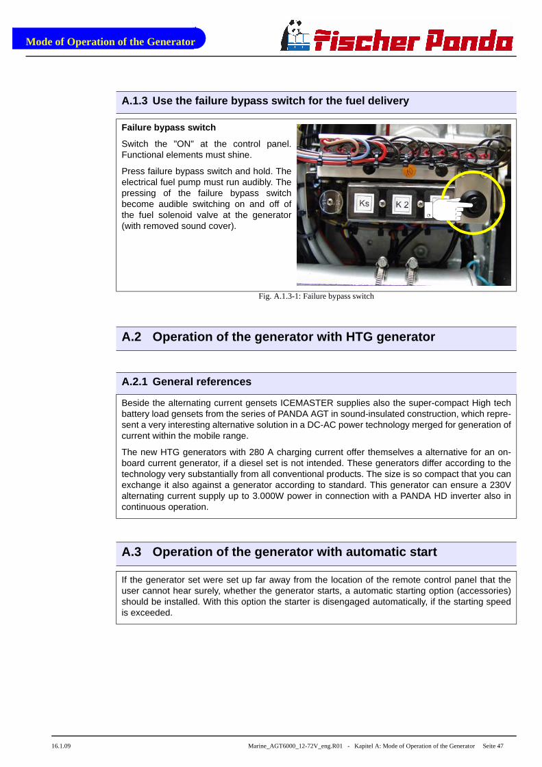
Failure bypass switch
Switch the "ON" at the control panel.Functional elements must shine.
Press failure bypass switch and hold. Theelectrical fuel pump must run audibly. Thepressing of the failure bypass switchbecome audible switching on and off ofthe fuel solenoid valve at the generator(with removed sound cover).
Fig. A.1.3-1: Failure bypass switch
A.2 Operation of the generator with HTG generator
A.2.1 General references
Beside the alternating current gensets ICEMASTER supplies also the super-compact High techbattery load gensets from the series of PANDA AGT in sound-insulated construction, which repre-sent a very interesting alternative solution in a DC-AC power technology merged for generation ofcurrent within the mobile range.
The new HTG generators with 280 A charging current offer themselves a alternative for an on-board current generator, if a diesel set is not intended. These generators differ according to thetechnology very substantially from all conventional products. The size is so compact that you canexchange it also against a generator according to standard. This generator can ensure a 230Valternating current supply up to 3.000W power in connection with a PANDA HD inverter also incontinuous operation.
A.3 Operation of the generator with automatic start
If the generator set were set up far away from the location of the remote control panel that theuser cannot hear surely, whether the generator starts, a automatic starting option (accessories)should be installed. With this option the starter is disengaged automatically, if the starting speedis exceeded.

Mode of Operation of the Generator
Seite 48 Marine_AGT6000_12-72V_eng.R01 - Kapitel A: Mode of Operation of the Generator 16.1.09
A.4 Operation of the generator with installation und er the waterline
If the generator cannot be installed clearly at least 600mm over the waterline, a vent valve mustbe installed into the raw water line. At installation beside the "midship´s line" a possible heelingmust be considered!
The water hose in the sound cover is split on the pressure side of the pump and extended in eachcase in the sound cover at both ends with a connecting nipple by a hose end. Both hose endsmust led out from the sound cover to a point, which is at least for 600mm over the waterline (ifpossible in the midship´s line). The valve is inserted at the highest place, at least 600mm over thewaterline.
Cut the hose rubber for the external valve vent.....
...and bent it upwards.
Both hose ends must be led out outside ofthe sound cover to one point, if possible600mm over the waterline in the midshipline. The valve is connected at the highestplace with the two hose ends.
Fig. A.4-1: Ventilation valve connection
A.4.1 Control of the vent valve
If the valve is blocked, the cooling water pipe cannot be ventilated after the stop of the generator,the water column is not interrupted and the water can penetrate into the combustion chamber ofthe engine.
This lead to destruction of the engine!

Mode of Operation of the Generator
16.1.09 Marine_AGT6000_12-72V_eng.R01 - Kapitel A: Mode of Operation of the Generator Seite 49
A.5 Operation of the generator with installation ove r the water-line
Generator over the waterline:
If the generator is installed over the waterline, a stronger impeller wear is possible, the pump canrun after the start some seconds dry.
It is very important that the impeller is exchanged every few months. When starting the generatorattention should be always paid and heard to it, when raw water withdraws from the exhaustneck. If this takes longer than 5 seconds the impeller must exchanged, he sucks in air before rawwater reaches the impeller (see picture below) and the impeller then wears strongly. In this casethe impeller loses his effect and raw water can penetrate into the engine as well as substantiallydestroy it. If the impeller is not exchanged early enough, the entire pump must be replaced.Otherwise the impeller wings breaks in pieces and it stresses some time to remove these again.Replacement impeller should always be on board.
With the installation of the generator it must be paid attention that the impeller pump is wellaccessible, since the impeller is a wearing part. If this place at the location can be reached notwell, an external pump with electric drive can be used instead of the pump built firmly in the soundcover, which should be installed in a well accessible place.
1. Raw water filter
2. Water cock
3. Hull inlet
Make certain that the raw waterfilter lies above the water level,otherwise with cleaning watercan penetrate by the hull inlet.
An external pre-pump canrelieve the impeller.
1
3
2

Mode of Operation of the Generator
Seite 50 Marine_AGT6000_12-72V_eng - Kapitel A: Mode of Operation of the Generator 16.1.09

Installation Instructions
16.1.09 Marine_AGT6000_12-72V_eng.R01 - Kapitel B: Installation Instructions Seite 51
B. Installation Instructions
B.1 Placement
B.1.1 Placement and Basemount
Since Panda generators have extremely compact dimensions they can be installed in tight locati-ons, attempts are sometimes made to install them in almost inaccessible places. Please considerthat even almost maintenance-free machinery must still remain accessible at least at the front(drive belt, water pump) and the service-side (actuator, dipstick). Please also note that in spite ofthe automatic oil-pressure sensor it is still essential that the oil level has to be checked regularly.
The generator should not be installed in the proximity of light walls, which can get into resonantvibrations by airborne sound. If this is not possible, these surfaces should line with 1mm lead foil,so the mass and the swinging behavior are changed.
Avoid to install the generator on a smooth surface with small mass (e.g. plywood plate). Thisaffects in the unfavorable case like an amplifier the airborne sound waves. An improvementobtains by compound these surfaces by ribs. Also break-throughs should be sawed, which inter-rupt the surface. Disguising the surrounding walls with a heavy layer (e.g. lead) plus foam mate-rial improves the conditions additionally.
The engine draws its inlet combustion air through several holes in the capsule base. Thereforethe capsule must be fitted with sufficient clearance between the capsule underside and the baseplate (min. 12mm (½")).
The generator sucks its air from the surrounding engine room. Therefore it must be ensured thatsufficient ventilation openings are present, so that the genset cannot overheat.
High temperature of the intake air decline the power of the genset and increases the coolant tem-perature. Air temperatures of more than 40°C reduce the power by 2% per temperature rise of5°C. In order to keep these effects as small as pos sible, the temperature in the engine roomshould not be higher than 15°C in relation to the o utside temperature.
B.1.2 Notice for optimal sound insulation
The convenient base consists of a stable fra-mework, on which the generator is fastened bymeans of shock-mounts.
Since the genset is "free" downward, the com-bustion air can be sucked in unhindered.
In addition are void the vibrations, which wouldarise with a closed soil.
Fig. B.1.2-1: Base

Installation Instructions
Seite 52 Marine_AGT6000_12-72V_eng.R01 - Kapitel B: Installation Instructions 16.1.09
B.2 Generator Connections - Scheme
The generator comes supplied with all supply lines (i.e. electric cables, fuel lines etc.) alreadyconnected to the motor and generator. The supply lines are fed through the capsule's front basepanel and are shielded at the capsule inlets with water-proof grommets.
All electrical connections, cable types and sizes m ust comply to the appropriate regulati-ons. The supplied cables are rated for ambient temp eratures up to 70°C (160°F). If thecables are required to meet higher temperature requ irements, they must be run throughconduits.
ATTENTION! Before working (installation) on the Sys tem read the section see “SafetyInstructions” on page iv in this Manual.
Fig. B.2-1: Generator Connections
Fig. B.2-2: Gemerator Connections
12
2 3 4 5 6 7 8 9 10 111
1. Raw water inlet2. Fuel supply (in)3. Fuel return line (out)4. Electrical cable for external fuel pump5. Oil drain hose6. Electrical cable to remote control panel
7. Cable to VCS-control8. Cable for voltage sense 24V9. Cable for shunt measurement10. Generator starter-battery negative (-) 11. Generator starter-battery positive (+) 12. Passage for service battery cable
1
3
2
1. In-flow from external cooling water expansion tank2. Return to external cooling water expansion tank
3. External ventilation valve
Installation Instructions
16.1.09 Marine_AGT6000_12-72V_eng.R01 - Kapitel B: Installation Instructions Seite 53
B.3 Cooling System Installation - Raw water
B.3.1 General References
The genset should have its own raw water (coolant water) inlet and should not be connected toany other engine systems. Ensure that the following installation instructions are complied with:
For the avoidance of galvanic corrosion the chapter "Service instruction for marine gensets (cor-rosion protection)“ is to be considered.
B.3.2 Installation of the thru-vessel fitting in Yac hts
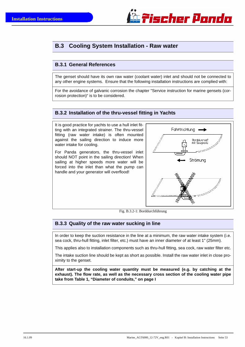
It is good practice for yachts to use a hull inlet fit-ting with an integrated strainer. The thru-vesselfitting (raw water intake) is often mountedagainst the sailing direction to induce morewater intake for cooling.
For Panda generators, the thru-vessel inletshould NOT point in the sailing direction! Whensailing at higher speeds more water will beforced into the inlet than what the pump canhandle and your generator will overflood!
Fig. B.3.2-1: Borddurchführung
B.3.3 Quality of the raw water sucking in line
In order to keep the suction resistance in the line at a minimum, the raw water intake system (i.e.sea cock, thru-hull fitting, inlet filter, etc.) must have an inner diameter of at least 1" (25mm).
This applies also to installation components such as thru-hull fitting, sea cock, raw water filter etc.
The intake suction line should be kept as short as possible. Install the raw water inlet in close pro-ximity to the genset.
After start-up the cooling water quantity must be m easured (e.g. by catching at theexhaust). The flow rate, as well as the necessary c ross section of the cooling water pipetake from Table 1, “Diameter of conduits,” on page I

Installation Instructions
Seite 54 Marine_AGT6000_12-72V_eng.R01 - Kapitel B: Installation Instructions 16.1.09
B.3.4 Installation above waterline
The Panda is equipped with a direct drive water intake pump mounted directly on the motor.Since the intake pump is an impeller pump there are wearing parts which will likely require repla-cement after some time. Ensure that the genset is installed such that the intake pump can beeasily accessed. If this is not possible, an external intake pump could be installed in an easilyaccessed location.
If the generator is installed above the waterline it is possible that the impeller wearout will bestronger. After the start the pump runs dry some seconds.
The raw water hose should describe a loop as near as possible to the raw water inlet of the gene-rator (see picture below). With it the pump only sucks in air for a short time. The impeller will belubricated by the raw water and its life time will rise.
By the installation of a check valve in the raw water inlet line, which is under the waterline, thisproblem can be limited a little .
It is very important to change the impeller every few month. When starting the generator youshould pay attention and listen when raw water comes out from the exhaust. If this lasts longerthan 5 seconds the impeller has to be changed, because he sucks to much air before raw waterreaches the impeller and the impeller wears out strongly. In this case the impeller looses itsfunction, which leads to an overheating of the engine.
If the impeller isn’t exchanged early enough, the impeller wings can break into pieces and clogthe cooling circuit. Therefore it is very important to change the impeller every few month.
NOTE:
Never change the impeller for many years, without exchanging the old pump. If the sealing ring isdefective within the pump, raw water runs into the sound cover of the genset. A repair is then veryexpensive.
Replacement impeller and also a spare pump should always be on board. The old pump can besent back to Fischer Panda, where it is then economically overhauled completely.

Installation Instructions
16.1.09 Marine_AGT6000_12-72V_eng.R01 - Kapitel B: Installation Instructions Seite 55
Fig. B.3.4-1: Installation Scheme
B.3.5 Installation below waterline
f the generator can not be attached at least 600mm over thewaterline, a vent valve must be installed into the raw waterline. With location beside the "midship line" a possible hee-ling must be considered! The water hose for the externalvent valve at the back of the sound cover splits on the pres-sure side of the pump and at both ends in each case exten-ded with a connecting nipple by a hose end. Both hose endsmust be led out outside of the sound cover to one point, ifpossible 600mm over the waterlinee in the midship line. Thevalve is connected at the highest place with the two hoseends. If the valve is blocked, the cooling water pipe cannotbe ventilated after the stop of the generator, the watercolumn is not interrupted and the water can penetrate into the combustion chamber of the engine.This leads to the destruction of the engine!
Fig. B.3.5-1: Vent Valve
1) Thru-hull fitting2) Hose nozzle3) Seavalve4) Raw Water Strainer5) Raw Water Pump
6) Heat Exchanger7) Fresh Water Pump8) Watercooled Exhaust Elbow9) Watercooled Diode Block10) Cooling Water Box

Installation Instructions
Seite 56 Marine_AGT6000_12-72V_eng.R01 - Kapitel B: Installation Instructions 16.1.09
Cut the hose for the external vent valve...
Fig. B.3.5-2: Hose for External Vent Valve
...and bent it upwards.
Both hose ends must be led out outside ofthe sound cover to one point, if possible600mm over the waterline in the midshipline. The valve is connected at the highestplace with the two hose ends.
Fig. B.3.5-3: Cut Hose for Connection External Vent Valve

Installation Instructions
16.1.09 Marine_AGT6000_12-72V_eng.R01 - Kapitel B: Installation Instructions Seite 57
Fig. B.3.5-4: Installation Scheme
1. Thru-Hull Fitting2. Hose Nozzle3. Seawalve4. Raw Water Filter5. Raw Water Impeller Pump6. Heat Exchanger
7. Fresh Water Pump8. Water Cooled Exhaust Elbow 9. Vent Valve10. Water Cooled Diode Block11. Expansion Tankl

Installation Instructions
Seite 58 Marine_AGT6000_12-72V_eng.R01 - Kapitel B: Installation Instructions 16.1.09
B.4 The Freshwater - Coolant Circuit
B.4.1 Position of the external Cooling Water Expansi on Tank
The Panda generator is normally sup-plied with an additional, external cool-ing water expansion tank. This tankmust be installed in such a way that itslower edge is at least 500mm morehighly arranged than the upper edge ofthe sound cover.
If this 500mm should be fallen below,i.e. the cooling water expansion tank islower installed, very large problemscan occur with filling and ventilating.Extend and displace the hose lines tothe outside or possibly even up to thedeck.
ATTENTION! The external cooling water expansion tan k may be filled onlyup to the lower edge of the lower tension tape (see note "max") in themaximum filling level in cold condition.
Fig. B.4.1-1: Position external Cooling Water Expansion Tank
B.4.2 Ventilating at the first filling of the intern al cooling water circuit
1. For the preparation of filling the following ste ps are to be undertaken:
a. Open the cooling water cap on thehousing of the water-cooled exhaustelbow union,
Fig. B.4.2-1: Cooling Water Cap

Installation Instructions
16.1.09 Marine_AGT6000_12-72V_eng.R01 - Kapitel B: Installation Instructions Seite 59
b. Vent screw on the thermostat housing,
Fig. B.4.2-2: Vent Screw at Themostate Housing
c. Vent screw on the pipe socket of theinternal cooling water pump.
Fig. B.4.2-3: Vent Screw at Pipe Socket
2. Filling the cooling water circle
a. Fill in the prepared mixture (coolingwater with anti-freeze protection accordingto the intended mixture) at the filler neck atthe housing of the water-cooled exhaustelbow union slowly so long, until coolingwater leaks at the de-aerating screw of thethermostat housing.
b. Afterwards the cooling water cap mustbe screwed on firmly. Further both de-aer-ating screws at the thermostat housingand at the internal cooling water pumpmust be closed.
Fig. B.4.2-4: Filling the Cooling Water Circuit
10
10

Installation Instructions
Seite 60 Marine_AGT6000_12-72V_eng.R01 - Kapitel B: Installation Instructions 16.1.09
Anti-freeze
In the interest of safety, the freezing point of the closed circuit coolant should be checked on aregular basis . Be sure that the coolant/antifreeze mixture is good for at least -15°C (5°F) and if itis possible that your genset experiences lower temperatures, for example during storage or trans-portation, then the entire cooling system should be drained and purged. To purge the coolingsystem, compressed air at about 0.5 bar (7.5 psi) is sufficient.
c. Fill up the external cooling water expansion tankwith coolant.
ATTENTION: „maximum fill level = „max.“-mark.
The cover of the external expansion tank tem-porary must be opened (all other closures are nowclosed!).
Fig. B.4.2-5: Cooling Water Expansion Tank
d. Start the generator
After filling the generator this must be started. During this first phase of start-up, the generator may not be loaded. Switch the generator off after max. 2 minutes of operation!
3. First de-aerating
The cooling water circuit of the generator must be de-aerated now by multiple repeating of thede-aerating procedure. During the entire procedure the external cooling water expansion tankremains opened (i.e. the cap must be removed).
After the first stopping of the the generator wait about one minute until the air in the cooling watercan be drop off and raise to the highest point (ventilation point).
Now open all three ventilation points one after another as long as cooling water exit. Then the clo-sure screw must be closed immediately. (Turn on only lightly to treat the thread.)
Pay attention that the external cooling water expansion tank is filled with enough cooling waterduring the de-aerating. (If necessary refill over and over.)
One de-aerating step will be last as a rule max. 2 minutes and following steps contained:
1. The generator runs approx. 1 minute.
2. Stop the generator.
3. Hold on one minute for drop of air.
4. The collected air is led out over the two de-aeration points.
The ahead described de-aerating process must be repeated as long as after the stopping and drop off air none air exit out of the de-aerating ports, only cooling water.

Installation Instructions
16.1.09 Marine_AGT6000_12-72V_eng.R01 - Kapitel B: Installation Instructions Seite 61
4. Again de-aerating process in the few days after the first startup
Also after the first implementing a small amount of air can be reside in the cooling circuit. Toensure an imaculate und actual operating of the cooling system the de-aerating process must berepeated casual in the next few days (if necessary weaks). Small amount of air will be still exit outof the de-aerating openings especially if the generator stood still for a long time.
ATTENTION! During the de-aerating process it must b e checked again andagain if the cooling water is indeed circulating. I f air bubbles establishedin the internal cooling water pump, it could be, th at the cooling water cir-cuit is not circulate. Then the generator would be warming very fast andswitched off by overheating.
B.4.3 Pressure test for control of cooling water cir cuit
Check with the hand if a temperature difference exists whether between cooling water in-flow andcooling water return.
Feel the cooling water in-flow line at the internal cooling water pump.
Feel the cooling water return pipe either at the outlet of the water-cooled exhaust elbow union orat the side, where this pipe entry at the heat exchanger.
The temperature difference between in-flow and return is approx 10 degrees.
B.4.4 Scheme for freshwater circuit at two circuit c ooling system
Fig. B.4.4-1: Scheme for freshwater circuit at two circuit cooling system
1) Thru-Hull Fitting2) Hose Nozzles3) Sea Valve4) Raw Water Filter5) Sea Water Pump
6) Heat Exchanger7) Fresh Water Pump8) Water Cooled Exhaust Elbow9) Water Cooled Diode Block10) Cooling Water Block

Installation Instructions
Seite 62 Marine_AGT6000_12-72V_eng.R01 - Kapitel B: Installation Instructions 16.1.09
B.5 Watercooled Exhaust System
By injecting the outlet raw water into the exhaust manifold, the exhaust gases are cooled and thenoise emissions from the exhaust system are reduced.
B.5.1 Installation des Standard-Abgassystems
The generator exhaust system must remain completely independent and separate from theexhaust system of any other unit(s) on board. The exhaust hose has an inner diameter of 40mm(1.6") (Panda 14000 and above approx. 50mm). The water lock must be installed at the lowestpoint of the exhaust system. An optional noise insulated water lock can also be installed. Theexhaust hose descends from the capsule to the water lock. Then the hose rises via the "gooseneck" to the silencer (see drawing). The goose neck must be vertical and sit preferably along theship's keel centre line. The exhaust system must be installed so that the back pressure inside theexhaust does not exceed 0.4 bar (6 psi) and total length does not exceed 6m (20 ft.).
Exhaust diameter see Table 1, “Diameter of conduits,” on page I.
Fig. B.5.1-1: Installation of the Standard Exhaust System
1. Generator2. Water lock3. Goose neck
4. Silencer5. Hull inlet

Installation Instructions
16.1.09 Marine_AGT6000_12-72V_eng.R01 - Kapitel B: Installation Instructions Seite 63
B.5.2 Exhaust / Water separator
The exhaust/water separator
In order to reduce the noise level of the generator unit to a minimum, an optional exhaust outletmuffler mounted next to the thru-hull fitting can be installed. Additionally there is component atFischer Panda, which exercise both functions of a "exhaust goose neck", and the water separa-tion. With this "exhaust/water separator" the cooling water is derived over a separate pipe. The-reby the exhaust noises at the exterior of the yacht are strongly decreased. Particularly the "waterplash" allocate.
The water flow on the exhaust/water separatorunit has an inner diameter (ID) of 30mm. If thepath from the water separator to the raw wateroutlet is very short, the hose can be further redu-ced to 1" (25mm) ID.
Fig. B.5.2-1: Exhaust / Water Separator
1. Raw water outlet ø 30mm
2. Hose connector ø 30mm
3. Reducer 30/20mm (if required)
4. Hose
5. Hose connector
6. Sea cock
7. Hull outlet
1. 8. Hose clips
Fig. B.5.2-2: Exhaust / Water Separator

Installation Instructions
Seite 64 Marine_AGT6000_12-72V_eng.R01 - Kapitel B: Installation Instructions 16.1.09
B.5.3 Installation exhaust/water separator
If the exhaust/water separator was sufficiently highly installed, a goose neck is no longer neces-sary. The exhaust/water separator fulfills the same function. If the "Supersilent" exhaust systemwere installed correctly, the generator will not disturb your boat neighbour. The exhaust noiseshould be nearly inaudible. The best result is reached, if the hose line, which derive the coolingwater, is relocate on a short way "falling" directly to the outlet and this outlet is under the water-line.
Fig. B.5.3-1: Installation Exhaust / Water Separator
If the thru-hull exhaust outlet has to be mounted far from the generator, an exhaust-water separa-tor must definitely be installed. The raw water from the separator must then run along the shortestpossible path is the thru-hull outlet. For such long exhaust routes, the exhaust hose diametershould also be increased from NW40mm to NW50mm in order to reduce the back-pressure. Theexhaust may have a length of over 10m (32 ft.) if the exhaust hose diameter is increased to50mm. An additional outlet exhaust muffler close to the hull outlet will help further to reduce noiseemissions.
1
5
6
2 3 4
1. Generator2. Silencer / Waterlock3. Wxhaust/water separator
4. Silencer5. Sea valve6. Hull outlet

Installation Instructions
16.1.09 Marine_AGT6000_12-72V_eng.R01 - Kapitel B: Installation Instructions Seite 65
Fig. B.5.3-2: Example for an unfavorable installation
Example of an unfavorable installation:
- water lock not deeply enough under the hights level of the generator
- distance water lock to exhaust/water separator too largely

Installation Instructions
Seite 66 Marine_AGT6000_12-72V_eng.R01 - Kapitel B: Installation Instructions 16.1.09
B.6 Fuel System Installation
B.6.1 General References
Inside the generator capsule itself, there is the fuel filter installed (Exception Panda 4500). Addi-tional fuel filters (with water seperator) must be mounted outside the capsule in easily accessibleplaces in the fuel lines between the tank intake fuel pump and the diesel motor's fuel pump.
Generally forward and return fuel flow pipes must be mounted to the diesel tanks. Do not connectthe generator fuel supply lines with any other fuel lines of other diesel systems.
The following items need to be installed:
- Fuel supply pump (12V-DC)
- Pre-filter with water separator (not part of the delivery)
- Fine particle fuel filter
- Return fuel line to fuel tank (unpressurized)
The fuel supply pump should be mounted as close to the fuel tank as possible. The electric cablefor the fuel pump is already installed on the generator (length 5m).
Fig. B.6.1-1: Anschluss an das Kraftstoffsystem
1 2 3 4 5
8
7
6
1. Generator2. Fuel stopcock3. Fuel filter4. Fuel return
5. Condensation water suction pump (optional)6. Fuel tank7. Fuel supply8. Electrical fuel pump (12V-DC)

Installation Instructions
16.1.09 Marine_AGT6000_12-72V_eng.R01 - Kapitel B: Installation Instructions Seite 67
B.6.2 The electrical fuel pump
Electrical fuel pump
With the Panda generator is usually supp-lied an external, electrical fuel pump (12VDC). The fuel pump must be installedclose at the fuel tank. The electrical con-nections are preloaded at the generatorwith the lead planned.
Fig. B.6.2-1: Electrical Fuel Pump
• Suction hight of the pump: max. 1,2m at 02, bar
• Diameter of fuel lines: Table 1, “Diameter of conduits,” on page I
B.6.3 Connection of the fuel lines at the tank
Lead the return fuel pipe connected to the day tank to the floor
The return pipe connected to the tank must be dropped to the same depth as the suction pipe, ifthe generfator is mounted higher than the tank, in order to prevent fuel running back into the tankafter the motor has been switched off, which can lead to enormous problems if the generator isswitched off for a long period.
Non-return Valve in the Suction Pipe
A non-return valve must be fitted to the suction pipe, which prevents the fuel flowing back afterthe generator has been switched off, if it is not possible to use the return flow pipe as a submergepipe be placing it in the tank. The instructions "Bleeding Air from the Fuel System" must be readafter initial operation or after it has stood still for a long period, in order to preserve the starter bat-tery.
ATTENTION! Non-return valve for the fuel return pip e
If the fuel tank should be installed over the level of the generator (e.g. dailytank), then a non-return valve must be installed in to the fuel return pipe toguaranteed that through the return pipe no fuel is led into the injectionpump.

Installation Instructions
Seite 68 Marine_AGT6000_12-72V_eng.R01 - Kapitel B: Installation Instructions 16.1.09
B.6.4 Position of the pre-filter with water separato r
Additionally to the standard fine filter a pre-filter with water separator must be installedoutside of the sound cover in the fuel sys-tem line. (is not included in delivery.)
Fig. B.6.4-1: Fuel Pre-Filter with Water Separator
B.6.5 Ventilating air from the fuel system
Normally, the fuel system is designed to vent out air itself i.e. as soon as the electric starter motorstarts operation the fuel pump starts working and the fuel system will be air-vent after some timeautomatically. It is nevertheless essential to vent the system as follows prior to the first operation(as all hoses are empty):
Switch main power switch on control panel "ON".
Push failure bypass switch and hold tight. The electric fuel pump has to be running audibly. Bymoving the failure bypass switch you can hear the solenoid valve of the generator starting andstopping (when the sound cover is taken off). After the fuel pump has been running 3 to 4 minutesbecause the failure bypass switch has been pushed down the vent screw of the solenoid valvehas to be unscrewed. When opening the screw one has to carry on pushing the switch. To avoidfuel getting in the sound cover a piece of cloth or absorbent paper should be put under the con-nection. As soon as fuel is running out without bubbles the air vent screw can be screwed inagain. Only now one can stop pushing the failure bypass switch.
Now the unit can be started by pushing the "START"-button. The unit should start after a shortwhile. Should the unit not start one of the pipe union nuts of a injection hose has to be unscrewedand one has to try again to start the unit. After the unit has started the pipe union nut has to betightened again.
Main power switch "OFF".
Fuel solenoid valve
Fig. B.1: Vent Screw at the Fuel Solenoid Valve

Installation Instructions
16.1.09 Marine_AGT6000_12-72V_eng.R01 - Kapitel B: Installation Instructions Seite 69
B.7 Generator 12 V DC System-Installation
The Panda Generators from Panda 8000 upwards have its own dynamo to charge a 12 V starterbattery.
It is recommended to install an additional starter battery for the generator.
The generator is then independent from the remaining battery set. This enables you to start thegenset at any time with its own starter battery even if the other batteries are discharged. A furtheradvantage of a separate starter battery is that it isolates the generator’s electric systemfrom thethe rest of the boat's DC system, i.e. minus pole (-) is not conected electrically to Earth/Ground.
The generator is then Earth/Ground free with regard to the rest of the boat.
B.7.1 Connection of the 12 V starter battery
The positive (+) battery cable is connecteddirecly to the solenoid switch of the starter.
Fig. B.7.1-1: Connection Starter Battery
The negative (-) battery cable is connec-ted to the engine foot.
Fig. B.7.1-2: Connection Starter Battery

Installation Instructions
Seite 70 Marine_AGT6000_12-72V_eng.R01 - Kapitel B: Installation Instructions 16.1.09
The Panda generators 8000 to 30 areequipped with various DC-relays, whichcan be found under the terminal strip. Thevarious relays have the following tasks(also see the DC circuit diagram)
1. Start-Relaiy
2. Pre-heat Relay (glow plugs)
3. Fuel Pump Start Relay
Fig. B.7.1-3: Terminal Strip
Alle Panda Generatoren sind mit einemeigenständigem 12 V-DC Anlasser ausge-stattet. Die Verbindungsleitungen von derBatterie zum DC-System sollten einen Lei-tungsquerschnitt von 25 mm² besitzen
1. Magnetschalter für Anlasser
2. Anlasser
Fig. B.7.1-4: Starter Motor
B.7.2 Installation of the remote control panel - see remote control panel manual
1 2 3
1
2

Installation Instructions
16.1.09 Marine_AGT6000_12-72V_eng.R01 - Kapitel B: Installation Instructions Seite 71
B.8 Generator DC System-Installation
ATTENTION! Before the electrical system is installe d, READ the SAFETYINSTRUCTIONS of this manual FIRST! Be sure that all electrical installati-ons (including all safety systems) comply with all required regulations ofthe regional authorities. This includes lightnening conductor, personalprotection switch etc.

Installation Instructions
Seite 72 Marine_AGT6000_12-72V_eng.R01 - Kapitel B: Installation Instructions 16.1.09
B.8.1 Installation Panda AGT 12-72V-system
Fig. B.8.1-1: Installation Panda AGT 24 V Sysetm
All electrical safety installations have to be made on board.
2
1. Generator2. Battery block 12-72V depending on system3. Battery monitor4. Fuel pump5. Remote control panel
6. Voltage control VCS7. Starter battery 12/24V depending on system8. Fuse9. Battery switch

Installation Instructions
16.1.09 Marine_AGT6000_12-72V_eng.R01 - Kapitel B: Installation Instructions Seite 73
Electrical fuses
It is absolutely essential that the electrical system installation is inspected by a qualified electricaltechnician. The generator should have its own AC input electrical fuses . The fuses should besized such that the rated current of the generator on each of the individual phases is not excee-ded by more than 25%.
Data for gensets with power output greater than 30kW on request!
The fuses must be of the slow type. A 3-way motor protection switch must be installed to protect the electrical motor.
Required cable cross-sections
The following recommended electrical cable dimensions (cross sections) are the minimum requi-red sizes for a safe installation. (see Table 3, “Cable cross section,” on page I)

Installation Instructions
Seite 74 Marine_AGT6000_12-72V_eng.R01 - Kapitel B: Installation Instructions 16.1.09
B.9 Voltage Control System
The VCS control is used for the adjustment of the number of revolutions of the engine and thusthe voltage of the generator. It belongs to the accessories and is externally attached.
VCS
Fig. B.9-1: Electronic Voltage Control VCS
ATTENTION!
The cable for the measuring voltage must be attach ed directly at the bat-tery, and may not attached to the output of the ele ctric rectifier.
By the voltage drop between generator and battery the accurate voltage canonly recieved direct at the battery. A false link can lead to damage the battery!
06
03
04
01
05
0709
02
08
01. Measuring voltage (+) (24V)02. Measuring voltage (-) (24V) 03. Actuator (+) 04. Actuator (-)05. Battery voltage supply (+)
06. Battery voltage supply (-)07. Stop-line (regulates the actuator back at shut-off
device)08. Terminal shunt-measurement 60mV DC (-)09. Terminal shunt-measurement 60mV DC (+)

Installation Instructions
16.1.09 Marine_AGT6000_12-72V_eng.R01 - Kapitel B: Installation Instructions Seite 75
B.10 Insulation test
ATTENTION: Once the electrical system installation is complete, a groundinsulation test must be performed as follows:
1.) Switch off all on-board electrical devices.
2.) Start the generator..
3.) Measure the AC-voltage with a voltmeter (adjust to Volt/AC) between:
a) generator housing and AC-Control box
b) generator housing and ground.
The measured voltage must not exeed 50mV (millivolts).
4.) Once the safety systems have been installed, they must be checked. If a leakage current relayhas been installed, it also has to be tested. In order to ensure that the leakage voltage relayfunctions properly, the individual generated phases from the generator must be checked betweeneach other, between phase and ground, (the single phase or 4th phase also needs to be checkedin this fashion).
5.) If the generator is protected by a ground connection, then ALL electrical devices, must also beconnected to this "common" ground (usu. ground contacts are attached to the devices' metallichousings).
The electrical system installation must also comply to the hook-up requirements of the shore cur-rent grid. Generally a leakage current relay is sufficient for safe electrical operation, however, thismust be confirmed by the electrical safety standard in the region where the system is attached toa main land power grid. The relay has to be meet the required safety standard regulations.
In addition to a proper circuit diagrams, terminal points, connections, electrical devices, etc. should also be labelled with stickers or signs
There is always the possibility that circuits have been rerouted/changed or individual componentshave not been not been correctly laid out on the circuit diagrams.
The installation electrician should therefore check and label all electrical connections to ensure that they correspond to the main circuit diagram. The inspection and correct labelling is especially critical for terminals L1/ L2/L3/L1'/N (for the 230V-50Hz model) and for terminals L1/L2/L3/N &1/2/ 4 for the 60Hz (120V) models. The electrician is therefore obliged, before installation to check whether the generator is earth-free. As long as this test has not been carried out all other components for electrical installation must be removed. Once the system has been installed and inspected, this test should also be performed with all electrical devices (i.e. voltage check bet-ween common and metallic housings) while the generator is running.

Installation Instructions
Seite 76 Marine_AGT6000_12-72V_eng.R01 - Kapitel B: Installation Instructions 16.1.09
B.11 Voltage controller
With a engine-operated generator set count always on the fact that through disturbances at thecontrolling of the diesel engine the control of the number of revolutions monitoring is lost. In thiscase the diesel engine could wind up without limitation and produce a voltage, which becomessubstantially larger than the electrical load can process. This can destroy very expensive items ofequipment. It must be take for granted that for the protection of the electrical load a voltage con-troller with isolating relays is used for a solid installation. The appropriate accessory componentsare available at Icemaster.
If it is about a duo combination generator, the voltage control for both output parts (single phaseAC and three-phase AC) should be planned.
At different PANDA generators a voltage control is integrated. This voltage control affects only thediesel engine. If the rated voltage exceed approx. 15%, this voltage control is activated, as thediesel engine is turned off. This is only possible with the delay of some seconds, load could bedamaged in the meantime. The only safe method for the protection of the electrical devices is theinstallation of an external voltage controller with separation contactor.
We recommend this measure with all reproduction and point out also that the generator manufac-turer is not responsible for damage, which are caused by overvoltage at external devices.
Protect your valuable devices by an external voltage controller!
Position of the external voltage controller
Reasonable the external voltage controller is mounted in such a way it works not only for thegenerator but for all AC voltage supplies in the electrical system, also for shore power and inver-ter. In these cases usually a selector switch is intended, which can be determined, which voltagesupply is switched to the electrical system. The voltage conteroller must be installed at the exit ofthe selector switch, thus in the electrical system.
B.11.1 Adjustment of the rated voltage
The voltage controller must be ordered for the appropriate rated voltage (12, 24, 32, 48, 42 VDC). Other voltage on request.
Changing between these voltages is not possible.
B.11.2 Functional decription of the voltage controll er
The voltage controller has 3 different adjustment possibilities:
upper switching point, lower switching point and time lag of the generator.
B.11.3Time lag of the switching points
For the upper as well as for the lower switching point a time delay is adjusted. That is, the voltagemust have overstep or fall short of the switching point on the time lag.

Installation Instructions
16.1.09 Marine_AGT6000_12-72V_eng.R01 - Kapitel B: Installation Instructions Seite 77
Additional notes to the recommendation "External, e lectrical voltage controller"
At Diesel engines count always on the fact that a diesel engine "revs up" due to special circum-stances uncontrolled. This is the case if by damage to the system engine oil arrives into the suck-ing in way. This is possible at many engines by the crank case exhaust. A crank damage couldcause for example that by overpressure too much oil is pressed into the crank case, so that thisoil arrives into the sucking in way. The engine cannot switch off itself any longer. Usually then adamage to the engine is the result. It would be fatal, even if this damage to the engine were thecause of the destruction of all switched on electrical load, because uncontrolled revving up of theDiesel engine leads also to an extreme increase of the voltage. Only by an external voltage con-troller with separation contactor can be prevented such damage.

Installation Instructions
Seite 78 Marine_AGT6000_12-72V_eng.R01 - Kapitel B: Installation Instructions 16.1.09

Maintenance Instructions
16.1.09 Marine_AGT6000_12-72V_eng - Kapitel C: Maintenance Instructions Seite 79
C. Maintenance Instructions
C.1 General maintenance instructions
C.1.1 Checks before starting
• Oil Level
• Cooling system leaks
• Visual check for any changes, leaks oil drain system, v-belt, cable connections, hose clips, air filter, fuel lines
Once a month
• Lubrication of actuator-trapezoid thread spindle
For Maintenance Intervalls see Table F.4, “Inspectio n checklist for services,” on Page VIII
C.1.2 Hose elements and rubber formed component in t he sound cover
Check all hoses and hose connections for good condition. The rubber hoses are very sensitive toenviromental influences. They can season fast with dry air, in which environment of muted oil andfuel steams and increased temperature. The hoses must be checked regularly for elasticity.There are operating situations, at which the hoses must be renewed once in the year.
Additionally to usual tasks of maintenance (oil level check, oil filter control etc.) further mainte-nance activities are to be accomplished for marine gensets. It belongs control of the sacrificialanode (cooling water connection block) and the front seal cover at the generator.
C.2 Oil circuit maintenance
The first oil change is to be accomplished after a period of operation from 35 to 50 hours. After-wards the oil is to be changed after 100 hours. For this the oil SAE30 for temperatures over 20°Cand SAE20 for temperatures between 5°C and 20°C is to be used. At temperatures under 5°C oilof the viscosity SAE10W or 10W-30 is prescribed.
Type and amount of required oil see:
See Table F.5, “Engine oil,” on Page IX and Table F.2, “Technical Data Engine,” on Page VI.

Maintenance Instructions
Seite 80 Marine_AGT6000_12-72V_eng.R01 - Kapitel C: Maintenance Instructions 16.1.09
C.3 Execution of an oil change
Oil drain hose
For the oil change an oil drain hose is leadthrough the sound cover.
Fig. C.3-1: Oil Drain Hose
Oil drain screw
The oil can be discharged by opening the oil drain screw. For countering use a second wrench.
Fig. C.3-2: Oil Drain Screw
13

Maintenance Instructions
16.1.09 Marine_AGT6000_12-72V_eng - Kapitel C: Maintenance Instructions Seite 81
Oil drain pump
If discharging of the oil is not possible, werecommend the employment of a handpump, which can be attached to the oildrain hose.
Afterwards the oil drain screw is closedagain.
Fig. C.3-3: Oil Drain Pump
Oil filter change
The oil filter can be loosen with an oil filterstrap.
Fig. C.3-4: Oil Filter Change
Oil filter gasket
Before the insertation of the new oil filterthe gasket should be coated with some-thing oil.
Tighten the oil filter only by hand.
Fig. C.3-5: Oil Filter Gasket

Maintenance Instructions
Seite 82 Marine_AGT6000_12-72V_eng.R01 - Kapitel C: Maintenance Instructions 16.1.09
Open the oil filler neck
After opening the cap of the oil filler neckthe new oil is refilled.
Please wait instant, before measure the oillevel, the oil must set off in the sump.
Fig. C.3-6: Open the Oil Filter Neck
Oil dipstick
With the help of the engine oil dipstick theoil level is to examined. The prescribed fil-ling level may not exceed the „Max“ mar-king.
We recommend 2/3 oil level.
Fig. C.3-7: Oil Dipstick
C.4 Checking the water separator in the fuel supply
The pre-filter with water separator has acock at its lower surface, with this cock thedownward sunk water can be discharged.
This is simply possible, water is heavierdue to its density than the Diesel.
Fig. C.4-1: Pre-Filter with Water Separator

Maintenance Instructions
16.1.09 Marine_AGT6000_12-72V_eng - Kapitel C: Maintenance Instructions Seite 83
C.4.1 Ventilating the fuel system
Normally, the fuel system is designed to bleed out air itself i.e. as soon as the electric startermotor starts operation the fuel pump starts working and the fuel system will be de-aerated aftersome time automatically. It is nevertheless essential to bleed the system as follows prior to thefirst operation (as all hoses are empty):
1. Switch the main power switch on control panel to „ON“. Functional components must illumi-nate.
2. Push failure bypass switch and holdtight. The electric fuel pump has to berunning audibly. By moving the failurebypass switch you can hear the sole-noid valve of the generator starting andstopping (when the sound cover istaken off).
Fig. C.4.1-1: Failure Bypass Switch
3. After the fuel pump has been running 3to 4 minutes because the failurebypass switch has been pushed downthe bleeding screw of the solenoidvalve has to be unscrewed. When ope-ning the screw one has to carry onpushing the switch. To avoid fuel get-ting in the sound cover a piece of clothor absorbent paper should be putunder the connection. As soon as fuelis running out without bubbles the airbleeding screw can be screwed inagain. Now stop pushing the failurebypass switch.
Fig. C.4.1-2: Fuel Solenoid Valve
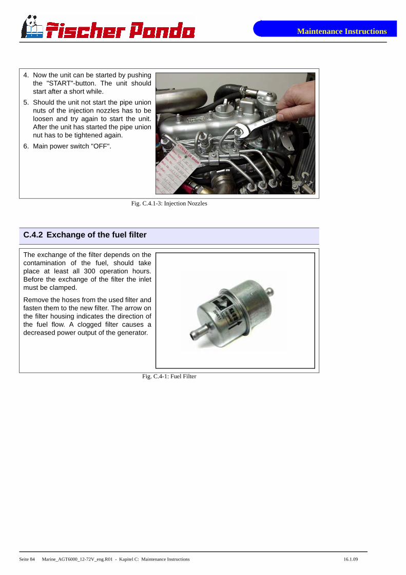
Maintenance Instructions
Seite 84 Marine_AGT6000_12-72V_eng.R01 - Kapitel C: Maintenance Instructions 16.1.09
4. Now the unit can be started by pushingthe "START"-button. The unit shouldstart after a short while.
5. Should the unit not start the pipe unionnuts of the injection nozzles has to beloosen and try again to start the unit.After the unit has started the pipe unionnut has to be tightened again.
6. Main power switch "OFF".
Fig. C.4.1-3: Injection Nozzles
C.4.2 Exchange of the fuel filter
The exchange of the filter depends on thecontamination of the fuel, should takeplace at least all 300 operation hours.Before the exchange of the filter the inletmust be clamped.
Remove the hoses from the used filter andfasten them to the new filter. The arrow onthe filter housing indicates the direction ofthe fuel flow. A clogged filter causes adecreased power output of the generator.
Fig. C.4-1: Fuel Filter

Maintenance Instructions
16.1.09 Marine_AGT6000_12-72V_eng - Kapitel C: Maintenance Instructions Seite 85
C.4.3 Exchange the air filter
Open the air suction housing by loosen thesix hexagon head screws on the housingcover.
Fig. C.4.3-1: Air Suction Housing
Change the air filter mat.
Fig. C.4.3-2: Opened Air Suction Housing
C.5 Ventilation of the coolant circuit / freshwater
Special notes for the ventilation of the cooling sy stem
If the cooling water is drained or if other air should have arrived into the cooling system, it isnecessary to de-aerate the cooling system. This de-aerate procedure must be repeated severaltimes:

Maintenance Instructions
Seite 86 Marine_AGT6000_12-72V_eng.R01 - Kapitel C: Maintenance Instructions 16.1.09
ATTENTION! Before opening the ventilatingpoints the generator must be stagnant!!
Pay attention that the external coolant expansiontank is connected with the generator by the twointended connection points.
Further it should be guatanteed that the expan-sion tank is attached in sufficient height (600mm9over the level of the generator exhaust elbowunion.
Fig. C.5-1: Expansion Tank
Open vent screw at the cooling waterpump.
Fig. C.5-2: Vent Screw at the Cooling Water Pump
Open vent screw at the thermostat hous-ing.
Fig. C.5-3: Vent Screw at the Thermostat Housing
10
10

Maintenance Instructions
16.1.09 Marine_AGT6000_12-72V_eng - Kapitel C: Maintenance Instructions Seite 87
Fill in cooling water into the cooling waterfiller neck. If it is to be recognized that thecooling water level does not fall anymore(with cold cooling water the cooling waterlevelmust cover the sheet metal in theexhaust elbow), close the filler-cap andthe cooling water screws and start thegenerator.
Run the generator for max. 60 seconds.
Stop the generator.
Fig. C.5-4: Cooling Water Filler Neck
Now the cooling water is only filled over the external expansion tank. This is connected by 2hoses with the genset.
The external expansion tank should be filled in the cold condition only up to maximally20%. It is very important that a large extension sp ace over the cooling water level remains.
Repeat this procedure several times.
If no change of the cooling water level can be determined, the generator is started for 5 minutes.Afterwards repeat the de-aeration two - three times.
It is meaningful to repeat the de-aeration procedure also after some days again to guarantee thatin the system remained bubbles are removed.
The vent screw over thehousing of the coolingwater pump may beopened under no circum-stances, while the gener-ator runs. If this happens
inadvertently, through the opening air issucked in. A very complex ventilation ofthe entire system is necessary thereafter.
Fig. C.5-5: Vent Screw over the Housing of the Cooling Water Pump

Maintenance Instructions
Seite 88 Marine_AGT6000_12-72V_eng.R01 - Kapitel C: Maintenance Instructions 16.1.09
C.5.1 Draining the coolant
In principle only describes here, how the cooling water of the raw water cycle can be drained. Themixture of the fresh water circuit should not be drained in principle. See measures for the prepa-ration of the winter storage.
The simplest and cleanest method consists of the fact to bring the external vent valve below thegenerator level and hold over a collecting basin. Open the valve now, the water from the rawwater circuit flows downward into the container..
C.6 Exchange of the v-belt for the internal cooling water pump
The relative high ambient temperature in the closed sound insulated capsule (about 85°C) can bea reason for a reduced lifespan of the v-belts. It is possible that the "softener" in the rubber com-pound lose their effect after a short operating time because the air in the sound insulated capsulecan be relative warm and dry.
The v-belt must be controlled in a very short time interval. It can be happen to change the v-beltafter some weeks because of unfavorably conditions. Therefore the control is needed in an inter-val of 100 operating hours. The v-belt ia a wearing part. It should be enough spare v-belts onboard. We suggest to stand by the according service-packet.
Loosen the fixing screw above the alterna-tor.
Fig. C.6-1: Fixing Screw above the Alternator

Maintenance Instructions
16.1.09 Marine_AGT6000_12-72V_eng - Kapitel C: Maintenance Instructions Seite 89
Loosen the fixing screw below the alterna-tor only a little bit.
Fig. C.6-2: Fixing Screw below the Alternator
Press the alternator to the direction of thethermostat housing.
Now the v-belt can be changed (type: XPZ850).
Fig. C.6-3: V-Belt
Stretch the v-belt by pulling the alternatorback. The v-belt should be able to be pres-sing approx. 1cm with the thumb.
Tighten the fixing srews above and belowthe alternator.
Fig. C.6-4: Drawing V-Belt

Maintenance Instructions
Seite 90 Marine_AGT6000_12-72V_eng.R01 - Kapitel C: Maintenance Instructions 16.1.09
C.7 The Raw Water Circuit
C.7.1 Clean Raw Water Filter
The raw water filter should be released regularlyfrom arrears. In each case the water cock mustbe closed before. It is mostly sufficient to beatthe filter punnet.
If water should seep through the cover of the rawwater filter, this may be sealed in no case withadhesive or sealant. Rather must be searchedfor the cause for the leakage. In the simplestcase the sealing ring between caps and filter hol-ders must be exchanged.
Fig. C.7.1-1: Raw Water Filter
C.8 Causes with frequent impeller waste
The impeller of the cooling water pump must be regarded as wearing part. The life span of theimpeller can be extremely different and exclusively depends on the operating conditions. Thecooling water pumps of the PANDA generators are laid out in such a way that the number ofrevolutions of the pump lies low compared with other gensets. This is for the life span of the pumpa positive effect.
Unfavorably affects the life span of the impeller, if the cooling water sucking in way is relativelylong or the supply is handicapped, so that the cooling water sucking in range develops a negativepressure. This can reduce first of all the power of the cooling water pump extremely that thewings of the impeller are exposed to very strong loads. This can shorten the life span extremely.
Further the operation of the impeller pump loaded in waters with a high portion of suspended mat-ters. The use of the impeller pump is particularly critical in coral waterbodies. Cases are well-known, which a impeller pump had so strongly run after 100 hours already that the lip seal on thewave was ground in. In these cases sharp crystal parts of the coral sand assess in the rubberseal and affect like an abrasive the high-grade steel shank of the impeller pump.
If the generator were mounted over the water level it is particularly unfavorable for the impellerpump. After the first start some seconds will pass by, until the impeller can suck in cooling water.This short unlubricated operation time damages the impeller. The increased wear can lead aftershort time to the loss. (see special notes: "Effects on the impeller pump, if the generator is moun-ted over the waterline")

Maintenance Instructions
16.1.09 Marine_AGT6000_12-72V_eng - Kapitel C: Maintenance Instructions Seite 91
C.8.1 Exchange of the impeller
Close the raw water stop cock.
Fig. C.8.1-1: Raw Water Stop Cock
Raw water pump on the front side of thegenerator.
Fig. C.8.1-2: Raw Water Pump

Maintenance Instructions
Seite 92 Marine_AGT6000_12-72V_eng.R01 - Kapitel C: Maintenance Instructions 16.1.09
Remove the cover of the raw water pumpby loosen the screws from the housing..
Fig. C.8.1-3: Raw Water Pump
Pull to the impeller with a multigrip pliers ofthe wave.
Mark the impeller, to make sure that theseis used in the correct position at re-installa-tion.
Fig. C.8.1-4: Seewasserpumpe geöffnet
Check to the impeller for damage andreplace it if necessary.
Before the reinsertion into the housing theimpeller should have been lubricated withglycerin or with a non-mineral oil basedlubricant e.g. silicone spray.
Fig. C.8.1-5: Impeller

Maintenance Instructions
16.1.09 Marine_AGT6000_12-72V_eng - Kapitel C: Maintenance Instructions Seite 93
The impeller is attached to the pump wave(if the old impeller is used, pay attention tothe before attached marking).
Fastening the cover and use a new seal.
Fig. C.8.1-6: Impeller

Maintenance Instructions
Seite 94 Marine_AGT6000_12-72V_eng.R01 - Kapitel C: Maintenance Instructions 16.1.09
C.9 Conservation at longer operation interruption
C.9.1 Measures on preparation of the winter storage
1. Rinse raw water circuit with an anti-freeze solution, even if this contains a corrosion protectionmeans. The raw water inlet must be removed at the water cock. Over a hose connector theanti-freeze protection mixture is to be sucked in from a container. The leaked cooling waterwith the exhaust is to be led back into the sucking in container. The circuit must be kept uprightsome minutes to guaranteed that the anti-freeze protection mixture reaches all ranges of thecooling system.
2. The concentration of the anti-freeze mixture in the internal cooling circuit must be checkedwith a suitable measuring instrument. The concentration must be furnished according to thelowest temperatures which can be expected.
3. Clean raw water filter and check seal.
4. Check water cock for practicability. And spray with a corrosion protection oil from the inside orlubricate with acidless grease.
5. Check all hoses and hose connectors for good condition. The rubber hoses are very sensitiveto enviromental influences. They can age fast with dry air, in environment of light oil and fuelsteams and increased temperature. The hoses must be checked regularly for elasticity. Thereare operating situations, which the hoses must be renewed once in the year.
6. Check the hose connectors at all raw water valves doubly and if possible protect them withdouble hose clamps.
7. Dismount the impeller of the cooling water pump and check for wear. The impeller may notremain in the pump. It must be greased with vaseline and be kept at a dark place. It can bereintragrated in the spring again into the pump, if it is in good condition. The impeller is a wea-ring part, it is recommended to renew it always in the spring, independently how many opera-ting hours the genset ran.
8. Control of the vent valve at the raw water inlet. If the generator is installed below the waterline,always a vent valve is necessary. The vent valve must be checked also during the seasonregularly. In the winter storage the vent valve should always be disassembled, checked andgreased. Hardens or got parts dirty are to be replaced.
9. Check water lock: If the generator were rinsed with an anti-freeze mixture, the antifreeze mix-ture can leave in the water lock. If the generator were rinsed with fresh water, the water in thewater lock must be drained. Otherwise the danger exists that the collector is blown up anddestroyed by ice.
10.Check the exhaust/water separator on leakage and if the hose connectors at the lower surfaceof the separation unit are in normal condition. (with extremely sulfureous fuels it is possiblethat also high-grade steel tube ends are attacked.)
11.Check all construction units at the generator inside the sound cover for leakages. If there aretraces of humidity in the sound cover, the cover must be dried. Further the cause for the wet-ness must be surched and eliminated.

Maintenance Instructions
16.1.09 Marine_AGT6000_12-72V_eng - Kapitel C: Maintenance Instructions Seite 95
12.During the winter storage the upper section of the sound cover must be taken off, in order toavoid condensed moisture formation, if traces of humidity remain in the sound cover insidecasing by leakages in the raw water circuit.
13.The generator housing and the housing of the engine should be sprayed with a corrosion pro-tection oil before the winter storage. This procedure is recommended also in the season. Thisprocedure can avoid that arising and humidity marks on the surface of the aluminum construc-tion units be noticed too late.
14.Disconnect the starter battery (positive and negative pole).
15.Lubricate the spindle for the number of revolutions adjustment device with a special lubricant(Antiseize grease).
16.Check cooling water connection block at the generator housing on traces of corrosion and ifnecessary renew. (only such traces are to be considered, which refer to clear "blossoming" ofthe material. If the surface is only grey coated, this is only an indication for the fact that alumi-num came into contact with condensed moisture.)
17.Use of a air dehumidifier. The best way to protect a yacht in the winter storage againstdamage by humidity is, to places a air dehumidifier inside the ship and locks all hatches. Thedevices have a hygrometer, which switches the device off, if the humidity is under the adjustedvalue. There is no better method, in order to protect pads, cable, electronics, wood, enginesetc. optimally against any rotting by humidity.
C.9.2 Initiation at spring
• Before the first start turn the engine once with the hand, in order to eliminate necessary existing corrosion beginnings in the bushing. If necessarily carry out normal engine inspection.
• Change engine oil and engine oil filters.
• Reintegrate the impeller of the cooling water pump and check pump for leakage.
• Charge starter battery of the generator, connect cables and check battery voltage.
• Start generator and check the basic adjustments of the generator such as voltage, speed regu-lation etc..
• Check all switching off devices for function by operational procedures.
Fischer Panda does not take over adhesion for possi ble damages!
C.9.1 Measures on preparation of the winter storage (Forts.) (Forts.)

Maintenance Instructions
Seite 96 Marine_AGT6000_12-72V_eng.R01 - Kapitel C: Maintenance Instructions 16.1.09

Generator Failure
16.1.09 Marine_AGT6000_12-72V_eng.R01 - Kapitel D: Generator Failure Seite 97
D. Generator Failure
D.1 Tools and Measuring Instruments
In order to be able to manage disturbances while dr iving, following tools and measuringinstruments should belong to the equipment on board :
• Multimeter for voltage (AC), frequency and resistance
• Measuring instrument for inductance
• Measuring instrument for capacity
• Current absorbing clamps
• Thermometer (ideal is a infrared thermometer)
• Pressure device (pincer) für coolant circuit
D.2 Überlastung des Generators
Please ensure that the genset is not overloaded. Overloading occurs when the electrical load(demand) induces a load torque in the generator which is higher than that which the diesel drivemotor can provide. Overloading causes the engine to run rough, burn oil, creates excessiveexhaust (environmentally unfriendly) and even to stall. Extra caution should be practised withmulti-power units (single and 3-phase current generation) to avoid overloading the diesel driveengine.
The generator should only be loaded at the peak rated power for short periods only! A high peakcurrent is required to start many electrical devices, especially electric motors and compressors(from a still stand state).
In order to prolong the genset´s life expectancy, t he nominal electrical demand on thesystem should not be more than 70% of the rated gen set peak load.
Keep PEAK LOADING demand in mind when switching on electrical devices (esp. fridge com-pressors, electric motors, battery chargers, kettles, etc.) which are fed by the generator. Careful"powering up" (gradual loading) of the electrical demand on the generator will help prolong the lifeof your genset! The genset can be run for several hours at partial load (i.e. 2/3 of rated power),however it is not advised that it is run for more than 2-3 hours at full load. The Panda is designedso as not to overheat even under extreme conditions. Note: The exhaust gas will become sootyduring peak-load operation.
Effects of Short Circuiting and Overloading on the Generator
The generator cannot be damaged by short circuiting or overloading. Short circuiting and over-loading suppress the magnetic excitation of the generator, thus, no current is generated and thevoltage will collapse. This condition is immediately offset once the short-circuit has been elimina-ted and/or the electrical overload removed.
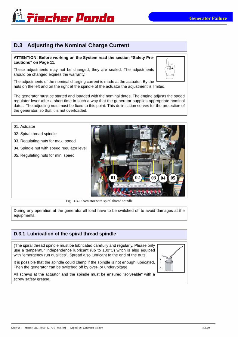
Generator Failure
Seite 98 Marine_AGT6000_12-72V_eng.R01 - Kapitel D: Generator Failure 16.1.09
D.3 Adjusting the Nominal Charge Current
ATTENTION! Before working on the System read the se ction “Safety Pre-cautions” on Page 11.
These adjustments may not be changed, they are sealed. The adjustmentsshould be changed expires the warranty.
The adjustments of the nominal charging current is made at the actuator. By thenuts on the left and on the right at the spindle of the actuator the adjustment is limited.
The generator must be started and loaaded with the nominal dates. The engine adjusts the speedregulator lever after a short time in such a way that the generator supplies appropriate nominaldates. The adjusting nuts must be fixed to this point. This delimitation serves for the protection ofthe generator, so that it is not overloaded.
01. Actuator
02. Spiral thread spindle
03. Regulating nuts for max. speed
04. Spindle nut with speed regulator level
05. Regulating nuts for min. speed
Fig. D.3-1: Actuator with spiral thread spindle
During any operation at the generator all load have to be switched off to avoid damages at theequipments.
D.3.1 Lubrication of the spiral thread spindle
(The spiral thread spindle must be lubricated carefully and regularly. Please onlyuse a temperatur independence lubricant (up to 100°C) witch is also equipedwith "emergency run qualities". Spread also lubricant to the end of the nuts.
It is possible that the spindle could clamp if the spindle is not enough lubricated.Then the generator can be switched off by over- or undervoltage.
All screws at the actuator and the spindle must be ensured "solveable" with ascrew safety grease.
01 02 03 04 05

Generator Failure
16.1.09 Marine_AGT6000_12-72V_eng.R01 - Kapitel D: Generator Failure Seite 99
01. Speed actuator
02. Spiral thread spindle
Fig. D.3.1-1: Drehzahl-Stellmotor
D.3.2 Effects of a overload to the actuator
If the generator is overloaded the voltage falls on account of a not adequate motor power underthe nominal value. The actuator stays at the upper keystroke and tries to rev up the diesel engine.An internal regulation limits the current to the actuator, nevertheless a longer overload candamage the winding of the actuator. (short of the winding). The motor gets not strictly inoperativebut it can happen that the cranking torque of the actuator is getting weak. This has the consecu-ence that the rev spindle can not be turned to all positions faultless. Therefore the voltage of thegenerator is regulated not good or sometimes not at all.
If you notice that the spindle of the actuator doesn´t run faultless, first check if the genset wasoverloaded for a short time and if thereby the winding of the actuator was damaged. Then theactuator has to be changed.
Check the electrical fuse (miniature slow-to-blow f use 1,6A) on the control printed circuitboard if the actuator will not turn at all.
Change this fuse
(1,6A slow to blow)
Fig. D.1: Fuse on the control plate
The generator can’t be damaged by an overload because the winding is overload- and short-cir-cuit safety. But damages are possible in the periphery. Especially connected load are endangeredbecause a lower voltage can damage them by order.
01 02

Generator Failure
Seite 100 Marine_AGT6000_12-72V_eng.R01 - Kapitel D: Generator Failure 16.1.09
Possible disturbances in the area of the rev regula tion "VCS"
Failure Cause
The spindle of the actuator jams • not regularly lubricated.
• surface is mechanical damaged.
• actuator is defect.
• defect of the VCS control (short of winding).
• signal DC missing.
• limiting nut jams the spindle.
Fuse on the printed circuit board of theVCS control is melted.
• constant overload of the generator.
Steps to check the voltage control by a disturbance :
1. Switch off all electrical load.
2. Disconnect the plug of the actuator.
3. Turn the actuator manually to check if the adjusting nut is jamed to the limit stop points.
4. Turn the actuator manually to check if the adjusting nut on the spindel runs faultless.
If there is no result by these steps the actuator is working mechanically correct. After this the elec-trical components must be checked:
1. Connect the plug of the actuator.
2. Start the generator.
3. Turn the actuator by hand and check if the spindle turns back by the motor.
4. If the motor react on the turn by manual strongly (the motor can normally hold with the fingers)the drive will be working faultless. If there are nevertheless faults in the voltage control there isa fault in the control VCS.
If the actuator is not moving the following points are necessary:
1. The motor turns not strongly rather weak:
• The actuator has shorts in the winding and must be changed. (pay attention that the generator is not overloaded anymore.)
2. The actuator does not move but the spindle can be turned manually. Disconnect the plug ofthe actuator. Connect provisional an external voltage source 12V-DC to the motor.
• The actuator don’t turns with the external voltage source. The actuator is defect and have to be changed.
Actuator does not move The actuator is defect and must be changed.
Actuator does move andworks mechanically correct
1. Check the fuse on the VCS printed circuit board.
2. Check if the sense voltage is wired to the VCS printed circuitboard.
3. Check if the VCS supply voltage is wired to the VCS.
4. Check if the VCS outlet signal for the actuator is wired.
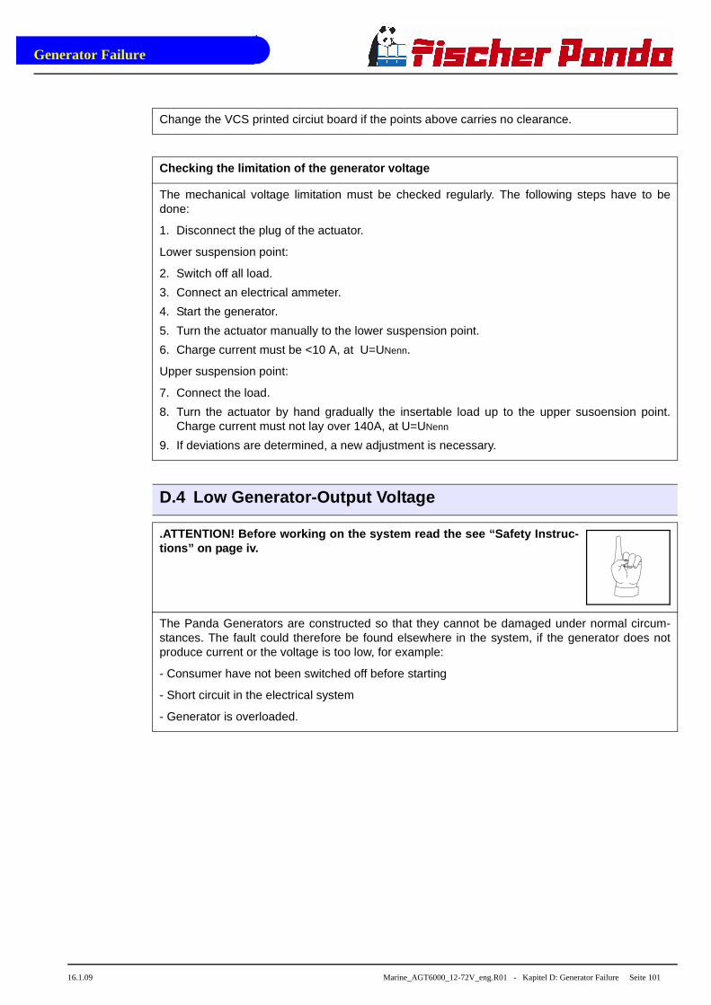
Generator Failure
16.1.09 Marine_AGT6000_12-72V_eng.R01 - Kapitel D: Generator Failure Seite 101
Change the VCS printed circiut board if the points above carries no clearance.
Checking the limitation of the generator voltage
The mechanical voltage limitation must be checked regularly. The following steps have to bedone:
1. Disconnect the plug of the actuator.
Lower suspension point:
2. Switch off all load.
3. Connect an electrical ammeter.
4. Start the generator.
5. Turn the actuator manually to the lower suspension point.
6. Charge current must be <10 A, at U=UNenn.
Upper suspension point:
7. Connect the load.
8. Turn the actuator by hand gradually the insertable load up to the upper susoension point.Charge current must not lay over 140A, at U=UNenn
9. If deviations are determined, a new adjustment is necessary.
D.4 Low Generator-Output Voltage
.ATTENTION! Before working on the system read the s ee “Safety Instruc-tions” on page iv.
The Panda Generators are constructed so that they cannot be damaged under normal circum-stances. The fault could therefore be found elsewhere in the system, if the generator does notproduce current or the voltage is too low, for example:
- Consumer have not been switched off before starting
- Short circuit in the electrical system
- Generator is overloaded.

Generator Failure
Seite 102 Marine_AGT6000_12-72V_eng.R01 - Kapitel D: Generator Failure 16.1.09
D.5 Prüfen der Generator Stator Wicklungen
ATTENTION! Before working on the system read the se e “Safety Instruc-tions” on page iv.
D.5.1 Testing Generator Stator Winding for "Shorts" to Ground
The generator stator windings can be tested as follows:
1. Ensure that the generator is "OFF" and cannot be accidentally started. Disconnect the battery.
2. Remove the cover of the power treminal box.
3. All terminal box connections are to be removed. (See appropriate circuit diagram.)
4. Remove all cables.
5. A check of the power terminal box is made by means of a multimeter to determine whetherthere is continuity between the individual windings connections.
If continuity is detected for any of the combinations, the generator must be sent to the factory forinspection and repair. If this is not possible, the stator can be rewound by a qualified tradesper-son/technician. Winding diagrams can be obtained from ICEMASTER GmbH, Germany.
This test, unfortunately, is carried out at very low voltage (9V) when a normal multimeter is used.Therefore only positive short circuits will be displayed. There is the possibility that a short circuitwill occur in spite of a negative test result (i.e. moisture). A reliable check can only be carried byusing an essentially higher voltage (approx 500V). This type of measuring instrument is normallyonly used by experts.
If in doubt an electrician must check the winding for a short circuit with an isolation meter.
Doide plate at the Panda generator
Fig. D.5.1-1: Diode Plate

Generator Failure
16.1.09 Marine_AGT6000_12-72V_eng.R01 - Kapitel D: Generator Failure Seite 103
Wiring Diagram
Fig. D.5.1-2: Wiring Diagram
D.5.2 Coil Resistance Measurements in Stator Winding s
If the testing set determined no earthing, the coil windings of the generator must be controlledwith a resistance measuring instrument (ohm meter). To measure coil resistance a meter capableof measuring low resistances (Milli-Ohm resolution if possible) accurately. The measured resi-stance values should be close to the same between the following terminals:
U1-U2, V1-V2, W1-W2
Checking windings.
• Disconnect all connections from the power terminal box. Loose the nuts and deduct the cables.
• Remove all winding connections from the power terminal box.
• Switch your meter in resistance range. When you put the probes of you meter together, you should get a reading of 0.00Ohm. When you isolate the probes, the reading will be Overflow. Please do this tests to check your meter.
• Measure of the resistance within the individual windings. The values should be very small. It mainly depends on the relation between the values. Some measuring instruments operate very inaccurately, if the measured values are very small.
• Resistance measure between different windings. If the value is in the Giga ohm area, the coil is correct.
If you find any anormality, when doing this test, please ask your Fischer Panda dealer.
If strong deviations are measured in the individual coil windings, there is a coil short-cut in onecoil. No voltage is induced.
The actual values between the coil windings are not determined so exactly. It depends on the factthat the values of all three measurements are as alike as possible. Deviations among themselvesrefer to a coil short-cut. In this case the generator must be newly wound by a specialist.

Generator Failure
Seite 104 Marine_AGT6000_12-72V_eng.R01 - Kapitel D: Generator Failure 16.1.09
D.5.3 Messung des induktiven Widerstandes
Unfortunately the checking of the ohmic resistance permits still no reliable statement about thecondition of the coil. If the ohmic resistance values arise inequalities between the coils, that is asafe indication for the fact that the coil is defective. To be exactly sure the inductive resistance ofthe coil have to be measured. For this a special measuring instrument is necessary, which mea-sures the inductance of a coil.
Inductance is measured in the same way as the ohmic resistance, i.e. the coils are compared.The value is indicated in mH (milli Henry).
Note: These values depends strongly from the measuring method (kind of the measuring instru-ment)
An alternative test method to check the stator wind ings can be performed as follows:
1. Ensure that the connection to the circuit system is disconnected.
2. All electrical wires in the power terminal box must be disconnected.
3. Reconnect the battery connections.
4. Start the generator.
5. Measure the voltages between the following terminals and compare for symmetry:
U1-U2, V1-V2, W1-W2

Generator Failure
16.1.09 Marine_AGT6000_12-72V_eng.R01 - Kapitel D: Generator Failure Seite 105
D.6 Starting Problems
D.6.1 VCS does not work
For start problems one chief cause is that the VCS doen not work. Check:
IIs the voltage sense connecttion ok?Check polatrity!
Fig. D.6.1-1: Checking VCS
Is the shunt connection ok? Check pola-trity!
Fig. D.6.1-2: Checking VCS

Generator Failure
Seite 106 Marine_AGT6000_12-72V_eng.R01 - Kapitel D: Generator Failure 16.1.09
Is the main supply connection ok? Checkpolatrity!
Does DP+ (VCS ON) lie on clamp 6 of theplug with 6 pins?
Fig. D.6.1-3: Checking VCS
Checking the fuse on the VCS printed cir-cuit board.
Fig. D.6.1-4: Checking VCS

Generator Failure
16.1.09 Marine_AGT6000_12-72V_eng.R01 - Kapitel D: Generator Failure Seite 107
D.6.2 Fuel Solenoid Valve and Stop Solenoid
For start problems the possibility of an error exists with the solenoid for engine stop or fuel sole-noid valve, which both effect affect simultaneous on the fuel system.
1. Fuel solenoid valve
The fuel solenoid valve is located in front of the injection pump. It opens automatically, if the"START"-button is pressed on the remote control panel. The solenoid valve is CLOSED when thegenerator main power is switched "OFF". For this reason, it requires a few seconds before themotor comes to a full halt
If the generator fails to start, runs rough, does not reach the proper RPM, or does not stop pro-perly, the first item to suspect in most cases is the fuel solenoid valve and should be inspectedfirst.
A check of the fuel solenoid valve by removing the plug from the fuel solenoid valve for a shortperiod whilst in operation (first remove the small retention screw) and replace it immediately. Themotor should "react immediately" by revving high.If the motor does not react sharply to the recon-nection of the solenoid wire, it is a sign that the solenoid valve could be faulty.
2. Solenoid for engine stop
The solenoid for engine stop is located at the injection pump.
1. Energized to stop
By pressing the "OFF"-button on the remote control panel, the solenoid is supplied with voltageand attracts, whereby the fuel injection pump resets to the zero position and the generator stops.
2. Energized to run
This version is equipped with two solenoids an actuating and a stop solenoid. After being fed withcurrent, the actuating solenoid attracts the adjusting lever of the fuel injection pump, throughwhich the fuel can flow. The actuating solenoid is switched parallel to the starter motor, the stopsolenoid is switched parallel to the fuel pump. The position is held by the stop solenoid as long asthe generator is running.
01. Fuel solenoid valve
02. Fuel injector nozzles
03. Ventilation screw
Fig. D.6.2-1: Kraftstoffmagnetventil
01
02
03
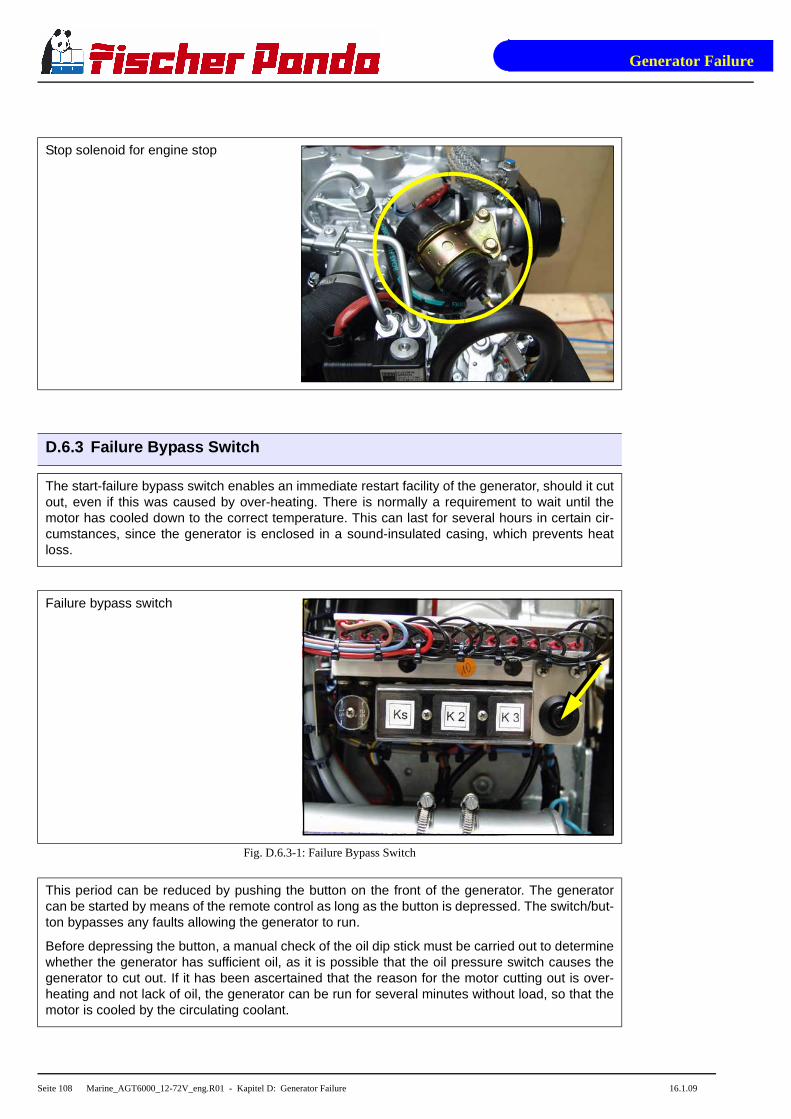
Generator Failure
Seite 108 Marine_AGT6000_12-72V_eng.R01 - Kapitel D: Generator Failure 16.1.09
Stop solenoid for engine stop
D.6.3 Failure Bypass Switch
The start-failure bypass switch enables an immediate restart facility of the generator, should it cutout, even if this was caused by over-heating. There is normally a requirement to wait until themotor has cooled down to the correct temperature. This can last for several hours in certain cir-cumstances, since the generator is enclosed in a sound-insulated casing, which prevents heatloss.
Failure bypass switch
Fig. D.6.3-1: Failure Bypass Switch
This period can be reduced by pushing the button on the front of the generator. The generatorcan be started by means of the remote control as long as the button is depressed. The switch/but-ton bypasses any faults allowing the generator to run.
Before depressing the button, a manual check of the oil dip stick must be carried out to determinewhether the generator has sufficient oil, as it is possible that the oil pressure switch causes thegenerator to cut out. If it has been ascertained that the reason for the motor cutting out is over-heating and not lack of oil, the generator can be run for several minutes without load, so that themotor is cooled by the circulating coolant.

Generator Failure
Seite 109 Marine_AGT6000_12-72V_eng.R01 - Kapitel D: Generator Failure 16.1.09
BEWARE:
If the temperature is the reason for the generator cutting out when it is running under load, thenan immediate check must be made to determine the cause. It could be a fault with the coolingsystem, one of the fans, the air-intake or a fault with the external cooling system.
Continual use of the starter-failure bypass switch should be avoided, while the generator cuts outduring operation.
The generator must always run without load for several minutes before being switched off, so thata temperature compensation occurs. Heat accumulation can cause the generator to overheat,even after ist has been switched off.
Should the overheating alarm be set off, caused by heat accumulation, after the generator hasbeen switched off, then this can also be bypassed using the switch.
D.7 Troubleshooting Table
For Troubleshooting see Table F.1, “Trouble shooting,” on Page II

Generator Failure
Seite 110 Marine_AGT6000_12-72V_eng.R01 - Kapitel D: Generator Failure 16.1.09

Tables
Marine_AGT6000_12-72V_eng - Chapter F: Tables Page 111
F. Tables
Table 1: Diameter of conduits
Generatortype
Ø Cooling water conduit Ø Exhaust con-duit
[mm]
Ø Fuel conduit
Fresh water
[mm]
Raw water
[mm]
Supply
[mm]
Return
[mm]
Panda PMS AGT 6000 20 20 40 8 8
Table 2: Technical Data
Type Nominal power [kW]
Continuous power [kW]
Nominal voltage [VDC]
Dauer-charging
current[A]
Nominal charging
current [A]
AGT 2500-12 2,5 2,5 12 180 180
AGT 2500-24 2,5 2,5 24 90 90
AGT 4000-12 4 3,2 12 220 280
AGT 4000-24 4 3,2 24 110 140
AGT 6000-12 5,5 4,8 12 290 360
AGT 6000-24 5,5 4,8 24 170 210
AGT10.000-24 10 8 24 290 360
AGT15.000-48 15 12 48 208 260
AGT20.000-48 20 16 48 290 360
AGT25.000-72 25 20 72 240 300
AGT30.000-96 30 24 96 208 260
AGT40.000-96 40 30 96 290 360
Table 3: Cable cross section
Length 1 - 3 m 4 - 6 m 7 - 10 m 11 - 15 m 16 - 20 m
16 mm² 70 A 63 A 55 A 48 A 42 A
25mm² 112 A 100 A 88 A 75 A 63 A
35mm² 155 A 140 A 125 A 110 A 95 A
50mm² 225 A 200 A 175 A 150 A 125 A
70mm² 315 A 285 A 250 A 220 A 190 A
95mm² 425 A 380 A 340 A 300 A 260 A
120mm² 540 A 490 A 440 A 400 A 360 A

Tables
Page 112 Marine_AGT6000_12-72V_eng - Chapter F: Tables
F.1 Trouble shooting
GENERATOR OUTPUT VOLTAGE TOO LOW
If the generator delivers less than 24V current ("undervoltage"), there can be various reasons for this:
Cause Solution
Generator is overloaded. Reduce the electrical load. (Switch off load)
Motor is not reaching the rated rpm. Refer to "motor faults" section.
Actuator is not in maximum position. Check actuator resp. renew.
VCS-voltage controler defective or wrong adjusted. Check resp. renew.
GENERATOR VOLTAGE TOO HIGH (MORE THAN 24V)
The following reasons may be the cause, if the generator delivers more than 24V ("overvoltage"):
Cause Solution
The engine is running at the wrong speed. Check the speed of the motor with a rev or frequencycounter, set the correct speed.
VCS-voltage controler defective or wrong adjusted. Check resp. renew.
Actuator defective. Check resp. renew.
GENERATOR VOLTAGE FLUCTUATES
Cause Solution
1. Fault or defect on the load side.
2. A motor fault.
1. Check if the power requirement of the load fluctua-tes.
2. See "Motor running irregularly".
MOTOR DOES NOT TURN OVER WHEN STARTING
Cause Solution
Battery main switch is switched off. Check the position of the battery main switch, if neces-sary switch on..
Battery voltage not sufficient. Check that connection is firm and whether corrosionhas occurred..
Starting current fault. The voltage of full batteries fall to a maximum of 11V.The wiring is severed if the voltage does not drop. Thebattery is discharged if the voltage drops further.

Tables
Marine_AGT6000_12-72V_eng - Chapter F: Tables Page 113
MOTOR TURNS OVER BUT DOES NOT START
Cause Solution
Stop solenoid valve not opening. Check wire connections and circuitry to solenoid valve.(ref. DC wiring diagram: Relay K2, Fuse)
Fuel pump does not operate. Check fuel-filter and pump: clean if necessary.
Lack of fuel. Check fuel supply.
Glow-plugs not working correctly. Check glow plugs and heating time.
Too much air in fuel lines. Test fuel system for leakage. Bleed air from fuelsystem (refer to section "Air-bleeding of the FuelSystem").
Fuel filter blocked. Replace fuel filter.
Low compression pressure. See Kubota motor-manual.
MOTOR DOES NOT TURN OVER AT THE NORMAL SPEED DURING THE STARTING PROCESS
Cause Solution
Starter battery voltage insufficient. Check battery.
Damaged bearing(s) piston (seized). Repairs need to be carried out by Kubota-Service.(refer to Kubota motor-manual)
Cooling water in combustion chamber. 1. Turn generator "OFF" at control panel.
2. Remove the glow plug (see Kubota-manual).
3. Rotate the motor by hand carefully.
4. Check if there is water in the oil and change both oiland filter if necessary.
5. Determine cause for excess water in the combustionchamber. The excess water can be caused by a defec-tive air vent in the cooling water system, which shouldbe checked and cleaned, or replaced if faulty.
MOTOR RUNS IRREGULARLY
Cause Solution
Faulty centrifugal injector governor. Have the centrifugal governor inspected by a Kubota-Service technician.
Too much air in fuel lines. Bleed air from fuel system.

Tables
Page 114 Marine_AGT6000_12-72V_eng - Chapter F: Tables
DROP IN THE SPEED OF THE MOTOR
Cause Solution
Too much oil. Drain oil.
Lack of fuel. Check fuel supply system:
- fuel filter, renew if necessary
- check fuel pump
- check fuel lines (bleed if necessary)
Lack of intake air. Check air intake paths.
Check and clean air filter (and intake muffler if instal-led).
Generator overloaded by too many load. Reduce the electrical load (switch off load).
Generator overloaded by over-energizing. Check that the proper capacitor type is installed andthat they are connected correctly.
Defective generator (windings, bearings, or other). Generator must be sent to manufacturer for repair ofdamaged bearings or winding.
Damaged engine. Repair of bearing damage, etc., by Kubota-Service.
MOTOR SWITCHES ITSELF OFF
Cause Solution
Fuel solenoid valve or throttle shut solenoid is not swit-ching off.
Check wire connections to solenoid. Check valvefunctions as in the "Inlet Fuel Solenoid Valve" or in thetrottle shut off solenoid sections. Replace if necessary.
MOTOR STOPS BY ITSELF
Cause Solution
Lack of fuel. Check fuel supply system.
Excess heat in cooling system (thermo switch tripped)-lack of cooling water. Is indicated on the remote controlpanel.
Check cooling water system flow: water pump, inletwater filter, extra heat exchanger coolant flow.
Lack of oil (oil pressure sensor tripped). Check oil-level and if necessary top up.
Check motor's oil-pressure and have repaired byKubota-Service if necessary.

Tables
Marine_AGT6000_12-72V_eng - Chapter F: Tables Page 115
SOOTY, BLACK EXHAUST
Cause Solution
Generator is overloaded. Check electrical load and switch off unnecessary load.
Insufficient intake air. Check intake air filter; clean if necessary.
Fuel injector nozzles faulty. Replace injector nozzles.
Valve clearance incorrect. Readjust valve clearance to correct value (refer toKubota-manual).
Poor fuel quality. Use better quality diesel (recommended: 2-D Diesel).
Poor combustion. Incorrect AFR (air/fuel ratio) due to motor timing adjust-ment. Have motor serviced by Kubota.
Low compression pressure. See Kubota motor manual.
GENERATOR MUST BE SHUT OFF IMMEDIATELY IF:
Cause Solution
- motor rpm suddenly rises or drops
- unusual noise comes from genset
- exhaust colour suddenly becomes dark
- motor overheats
- oil pressure drops, oil light suddenly flashes
Refer to respective section of manual and if necessary,have repaired by Kubota-Service, or Panda represen-tative.
TROUBLESHOOTING VCS SYSTEM
Cause Solution
Actuator does not move. Check voltage supply and wire connections to actuator.
Motor connected?
Check connection to VCS.
Actuator sets throttle too high or too low. Check that the wires to the actuator are connected pro-perly (±).
Check connection to VCS.
If the VCS electronics are faulty, the generator can still run by over-riding the system. To override the VCS, dis-connect the plug and jumper the contacts.
Loosen the connecting rods motor from the injection pump regulator and turn screw to a max. voltage of 33V.

Tables
Page 116 Marine_AGT6000_12-72V_eng - Chapter F: Tables
F.2 Technical Data Engine
Panda AGT 6000 PMS
Type Z482
Govenour VCS
Cylinder 2
Bore 67mm
Stroke 68mm
Stroke volume 479cm3
max- power (DIN 6271-NB) at 3000 rpm 9,32kW
Rated speed 50Hz 3000rpm
Idle running speed a
a. progressive speed by VCS
2900rpm
Valve clearance (engine cold) 0,2mm
Cylinder head torque 42Nm
Compression ratio 23:1
Lubrication oil capacity 2,5l
Fuel consumption b
b. 0,35l/kW electrical power, the randomized values between 30% and 80% of the nominal power
ca. 0,58 - 1,54 l
Oil consumption max. 1% of fuel consumption
Cooling water requirement for raw water circuit 16-28l/min
Permissible max. permanent tilt of engine a) 25° acr oss the longitudinal axis
b) 20° in the longitudinal direction

Tables
Marine_AGT6000_12-72V_eng - Chapter F: Tables Page 117
F.3 Types of Winding
HP3 delta-connection
HP3 star-connection

Tables
Page 118 Marine_AGT6000_12-72V_eng - Chapter F: Tables
F.4 Engine oil
Engine oil classification
Operating range:
The operating range of an engine oil is determined by SAE class. "SAE" is for the union of American engineers(Society of Automotives Engineers). The SAE class of an engine oil only informs over the viscosity of the oil (lar-ger number = more viscous, lower number = more highly liquidly) e.g. to 0W, 10W, 15W, 20, 30, 40. The firstnumber shows the liquid of cold weather, the second number refers to the fluidity with heat. Complete yearly oilshave usually SAE 10W-40, SAE 15W-40 etc.
Quality of oil:
The quality of an engine oil is specified by the API standard ("American Petroleum Institutes"). The API designa-tion is to be found on each engine oil bundle. The first letter is always a C.
API C for diesel engines
The second letter is for the quality of the oil. The more highly the letter in the alphabet, the better the C für Diesel-motoren.
Examples for diesel engine oil:
API CG Engine oil for highest demands, turbo-tested
Engine oil types
above 25°C SAE30 or SAE10W-30
SAE10W-40
0°C to 25°C SAE20 or SAE10W-30
SAE10W-40
below 0°C SAE10W or SAE10W-30
SAE10W-40

Tables
Marine_AGT6000_12-72V_eng - Chapter F: Tables Page 119
F.5 Coolant specifications
Use a mixture of water and antifreeze. The antifreeze needs to be suitable for aluminium. The antifreeze concen-tration must be regularly checked in the interests of safety.
ICEMASTER recommend to use the product: GLYSANTIN PROTECT PLUS/G 48
Engine coolant automotive industry Product descript ion
Product name GLYSANTIN ® PROTECT PLUS / G48
Chemical nature Monoethylenglycol with inhibitors
Physical form Liquid
Chemical and physical properties
Reserve alkalinity of 10ml ASTM D 1121 13 – 15 ml HCl 01 mol/l
Density, 20°C DIN 51 757 procedure 4 1,121 – 1,123 g/cm3
Water content DIN 51 777 part 1 max. 3,5 %
pH-value undiluted 7,1 – 7,3
Coolant mixture ratio
Water/antifreeze Temperature
70:30 -20°C
65:35 -25°C
60:40 -30°C
55:45 -35°C
50:50 -40°C

Tables
Page 120 Marine_AGT6000_12-72V_eng - Chapter F: Tables

VCS-AGT-U/I
Page 121 - Chapter A: VCS-AGT-U/I VCS-AGT-UI_eng.fm
Fischer Panda DatasheetA. VCS-AGT-U/I
A.1 VCS-AGT-U/I Versions
Art. Nr.: Set point Art. Name
F1RORE9627-012-212 12V VCS-AGT-U/I 12V= @60mV
F1RORE9627-024-212 24V VCS-AGT-U/I 24V= @60mV
F1RORE9627-036 36V VCS-AGT-U/I 36V= @60mV
F1RORE9627-048 48V VCS-AGT-U/I 48V= @60mV
F1RORE9627-072-212 72V VCS-AGT-U/I 72V= @60mV
F1RORE9627-080-212 80V VCS-AGT-U/I 80V= @60mV
auf Anfrage / on request 96V VCS-AGT-U/I 96V= @60mV
auf Anfrage / on request 115V VCS-AGT-U/I 115V= @60mV
F1RORE9627-120 120V VCS-AGT-U/I 120V= @60mV
F1RORE9627-144 144V VCS-AGT-U/I 144V= @60mV
F1RORE9627-180 180V VCS-AGT-U/I 180V= @60mV
auf Anfrage / on request 300V VCS-AGT-U/I 300V= @60mV
auf Anfrage / on request 320V VCS-AGT-U/I 320V= @60mV
auf Anfrage / on request 336V VCS-AGT-U/I 336V= @60mV
A.2 Voltage control system
Fig. A.2-1: VCS view
1
3
42
1. Terminals 7+82. Potentiometer for the charging voltage
3. Terminals 1-64. Programming

VCS-AGT-U/I
Page 122 - Chapter A: VCS-AGT-U/I VCS-AGT-UI_eng.fm
Fischer Panda Datasheet
Fig. A.2-2: VCS view
The VCS control is used for the adjustment of the number of revolutions of the engine and thus the voltage of thegenerator. It belongs to the accessories and is externally attached.
No. Short mane IN/OUT Function
1 + Actuaror O Out (+) for actuator
2 - Actuator O Out (-) for actuator
3 +12V I Operation voltage(+); 12V-Automotive
4 0V I Operation voltage(-); 12V-Automotive
5 AC Controllamp O to 0V - Optional
6 VCS on I 12V: VCS is on / open : VCS is off
7 Mesurement voltage + I Mesurement voltage (+) from the generator
8 Mesurement voltage - I Mesurement voltage (-) from the generator
9 Mesurement current + I Mesurement current (+) from the generator
10 Mesurement current - I Mesurement voltage (-) from the generator
Fig. A.2-3: Terminals of the VCS
The potentiometer next to clamp 7/8 is needed for adustment of the measurement voltage and should be done byan service technican only.
The potentiometer next to clamp 9/10 is needed for adustment of the measurement current and should be doneby an service technican only.
1
2
1. Terminals 9+10 2. Potentiometer for the charging current

VCS-AGT-U/I
VCS-AGT-UI_eng.fm Chapter A: VCS-AGT-U/I - Page 123
Fischer Panda Datasheet
A.2.1 Gerneral working of the VCS
When the VCS is active (+12V on clamp 6) the VCS controls the actuator to reach the exact voltage.
The mesurement voltage is taken from the generator by an shunt which has 60mV nominal.
A.2.2 Safety instructions for the voltage control
• A broken cable in the mesurement line will be notice by the VCS and the generator will slow down and stop.
• A short circiut in the mesurement line or a wrong pol connection is not noticed by the VCS (its like that there is no voltage). The voltage control in this vase ist out of funktion. It is necessary at the installation to check the right working of the VCS and a second overvoltage protection must be installed.
• For the mesurement voltage a shieldet cable is needet, it must be less than 3 mtr long. The shield should be connected to ground at one side.
Note the safety instruction in the generator manual !
Please Note!
• Run the generator with closed sound cover only
• Recommend: install a smoke connection.
• Ask for regular service

VCS-AGT-U/I
Page 124 - Chapter A: VCS-AGT-U/I VCS-AGT-UI_eng.fm
Fischer Panda Datasheet
Intentionally Blank

Pan
el G
ener
ator
Con
trol
P6+
RE
0703
_Kun
de_e
ng.R
0416
.1.0
9
Generator Control Panel P6+ Manual
12V version - 21.02.02.009H 24V special version - 21.02.02.012H
Option automatic adapter - 21.02.02.016HOption master-slave adapter - 21.02.02.015H
Fischer Panda GmbH

126
Current revision status
Document
Actual: Panel Generator Control P6+ RE0703_Kunde_eng.R04_16.1.09
Replace: Panel Generator Control P6+ RE0703_Kunde_eng.R03
Revision Page
Upgrade the whole manual
Safety instruktion See valve added
Hole pattern changed
ATTENTION!: Please read the safety instructionsin your generator manual!

General operation
16.1.09 Panel Generator Control P6+ RE0703_Kunde_eng.R04 - Chapter A: General operation Page 127
A. General operation
A.1 Panel Generator Control
Fischer Panda Art. No. 21.02.02.009H
1 LED green: normal operation mode, LED red: fault, LED yellow: warning, LED orange: active
Fig. A.1-1: Panel front
01 02 03 04
11 12 14 1513
05 06 07
08 09 10
01. LED for coolant temperature red1
02. LED for waterleak red/yellow1 (sensor optional)
03. LED for AC-voltage fault red/yellow1
04. LED for AC-voltage ok green1
05. LED for winding temperature red1
06. LED for oil pressure red1
07. LED for battery charge voltage fault green/red1
08. LED for pre-glow „heat“ orange1
09. LED for Generator „start“ green1
10. LED for Generator „stand-by“ green1
11. Push button for pre-glow „heat“12. Push botton for Generator „start“13. Operating hours counter14. Push button panel „off“15. Push button panel „on“

General operation
Page 128 Panel Generator Control P6+ RE0703_Kunde_eng.R04 - Chapter A: General operation 16.1.09
A.2 Rear view 12V-version
Fischer Panda Art. No. 21.02.02.009H
Fig. A.2-1: Panel rear view 12V-version
0201
03 04
01. Control board02. Terminal block (master-slave adapter: left row; automatic adapter: right row)03. Terminals 1-12 (see section A.3.1, “Terminal connections,” on page 130)04. Fuse 630mA slow-blow

General operation
16.1.09 Panel Generator Control P6+ RE0703_Kunde_eng .R04 - Chapter A: General operation Page 129
A.3 Rear view 24V-version
Fischer Panda Art. No. 21.02.02.012H
Fig. A.3-1: Panel rear view 24V-version
0201
04 05 06
03
01. Control board02. Terminal block (master-slave adapter: left row; automatic adapter: right row)03. Fuse 630mA slow-blow04. Terminals 1-12 (see section A.3.1, “Terminal connections,” on page 130)05. Linear controller 24V06. Linear controller 24V

General operation
Page 130 Panel Generator Control P6+ RE0703_Kunde_eng.R04 - Chapter A: General operation 16.1.09
A.3.1 Terminal connections
Standard for NC temperature switch configured i.e. in case of failure „open“.
Clamp no.
Clamp name
IN / OUT
Description
1 Vbat IN Current supply + 12V (or optional 24V, must be adjusted by jumper)
2 GND IN Current supply -
3 T-Engine IN
Error “coolant temperature”. Input for thermo-switch to GND. The input is adjustable for NC/NO(N = no error) (must be adjusted by solder Jumper). The input loads the switch with ≥22mA to+12V (with 24V-operated internally generated). The occurrence of an error is delayed, for ana-lysis and displayed, around 100ms. Omission not. The in/out status is indicated with red LED.
4 Water leak(Replace air fil-ter)
IN
Error “water leak”. Input for sensor switch to GND. The input is adjustable for NC/NO (N = noerror) (must be adjusted by solder Jumper). The input loads the switch with ≥10mA to +12V(with 24V-operated internally generated). The occurrence of an error is delayed, for analysisand displayed, around 100ms. Omission not. The input status is indicated with red LED.
The input can be used alternatively for the signal “Replace air filter” (must be adjusted by sol-der Jumper). Then the signal does not lead to switching off and is indicated with yellow LED.
5 Oil-Press IN
Error “oil pressure“. Input for oil pressure switches to GND. The input is adjustable for NC/NO(N = no error) (must be adjusted by solder Jumper). The input loads the switch with ≥22mA to+12V (with 24V-operated internally generated). The occurrence of an error is delayed, for ana-lysis and displayed, around 1s. Omission not. The input status is indicated with red LED.
6 DC-Control IN /OUT
Load control display. Input for signal of the dynamo. The input is adjustable for GND = OK or12V/24V = OK (must be adjusted by solder Jumper). The input loads the signal with 5mA at12V and 10mA at 24V. The input status is indicated with red and green LED.
The connection can supply an energizing current for the dynamo over a fixed resistor with 68R.Either with the control panel switched on or with “Fuel pump” switched on (must be adjusted bysolder Jumper). This function is available only in 12V-operation.
7 AC-Control IN AC control display. Input for NC-open-collector-sensor-switch to GND (N = OK). The inputloads the switch with ≥2,5mA to +12V (with 24V-operated internally generated). The input sta-tus is indicated with red and green LED´s.
8 Heat OUT Output for pre-glow relays. The output is so long active, as the button “Heat” is pressed. Theoutput supplies, if active, the voltage of clamp 1. Additionally the output can be operated via thebutton “start” (must be adjusted by solder Jumper). Consider (notes 1-4).
9 Fuel-Pump OUT
Output for fuel pump relay. The output is active, if no error is present (inputs 3, 4, 5, 11 and 12,if configured accordingly). The button “start” suppresses the error analysis and the output isthen also active in the case of error, if the button “start” is pressed. The output supplies, ifactive, the voltage of clamp 1. Consider (notes 1-4).
10 Start OUT Output for starting relay. The output is active, as long as the button “start” is pressed. The out-put supplies, if active, the voltage of clamp 1. Consider (notes 1-4).
11 AC-Fault (FuelLevel) [former T-Oil]
IN
Error generator AC input for NC-open-collector-sensor-switch to GND (N = no error). The inputloads the switch with ≥2,5mA to +12V. (with 24V-operated internally generated). The occur-rence of an error is delayed, for analysis and displayed, around 100ms. Omission not. Theinput status is indicated with red LED.
The input can be used alternatively for the signal “Fuel level” (must be adjusted by solder Jum-per). The signal does not lead to switching off and is indicated with yellow LED.
The input can be used alternatively for the signal “error oil-temperature”. The input is adjustablefor NC/NO (N = no error) (must be adjusted by solder Jumper). The load of the sensor switch isadjustable to ≥10mA by +12V (must be adjusted by solder Jumper).
12 T-Winding IN
Error “winding temperature”. Input for thermo-switch to GND. The input is adjustable for NC/NO(N = no error) (must be adjusted by solder Jumper). The input loads the switch with ≥22mA to+12V (with 24V-operated internally generated). The occurrence of an error is delayed, for ana-lysis and displayed, around 100ms. Omission not. The input status is indicated with red LED.
Fig. A.3.1-1: Terminal connections

General operation
16.1.09 Panel Generator Control P6+ RE0703_Kunde_eng .R04 - Chapter A: General operation Page 131
Notes:
1. Power rating of the output: max. 0,5A in continuous operation and briefly 1,0A.
2. The supply of all output currents may not exceed (less 0,2A power consumption) the rated current of the safetydevice of the control panel.
3. The output has a free wheeling diode, which short circuits negative voltages (related to GND).
4. The output has a Z-diode, which prevents a supply of positive voltage (related to GND) into the output.
A.3.2 Function of the jumpers
Jumper Status Description
J1closed during operation of the start button heat is along-operated
open Function deactivated
J3
1-2 Dynamo excitation resistor 68R is switched on with Fuel-Pump (1)
2-3 Dynamo excitation resistor 68R is switched on with Panel-ON (1)
open Dynamo excitation resistor is deactivated
J101closed 12V - operation
open 24V - operation (optional)
J2011-2 T-Engine-input, for contact, which opens in case of error (2)
2-3 T-Engine-input, for contact, which closes in case of error (2)
J202 1-2 Water leak-input / Replace air filter, for contact, which opens in case of error (2)
2-3 Water leak-input / Replace air filter, for contact, which closes in case of error (2)
J203 1-2 Oil-Press-input, for contact, which opens in case of error (2)
2-3 Oil-Press-input, for contact, which closes in case of error (2)
J204 1-2 AC-Fault-input / Fuel level, for contact, which opens in case of error (2)
2-3 AC-Fault-input / Fuel level, for contact, which closes in case of error (2)
J205 1-2 T-Winding-input, for contact, which opens in case of error (2)
2-3 T-Winding-input, for contact, which closes in case of error (2)
J206 1-2 Input Water leak has red LED and switches off
2-3 Input Water leak has yellow LED and does not switch off
J207 1-2 Input AC-Fault has red LED and switches off
2-3 Input AC-Fault has yellow LED and does not switch off
J208 1-2 DC-Control-Signal (-) = OK dynamo 12V at Kubota Z 482 / D 722 engines
2-3 DC-Control-Signal (+) = OK three-phase DC-alternator
J2091-2 DC-Control-Signal (-) = OK dynamo 12V at Kubota Z 482 / D 722 engines
2-3 DC-Control-Signal (+) = OK three-phase DC-alternator
J210 closed Input AC-Fault has Pull-Up-current ≥10mA
open Input AC-Fault has Pull-Up-current ≥2,5mA
Fig. A.3.2-1: Function of the solder jumper

General operation
Page 132 Panel Generator Control P6+ RE0703_Kunde_eng.R04 - Chapter A: General operation 16.1.09
The solder jumpers are marked on the printed circuit board (with jumper no. and at three-part solder jumper withsoldering surface no.)
(1): Equivalent resistance for load control lamp e.g. for use with three-phase alternator also integrated automaticcontroller of Bosch. The resistance value is 68Ω 3W, i.e. only for 12V.
(2): A closed contact switches the appropriate input to GND.
A.3.3 Configuration and adjustment
Configuration and setting sheet KE01
Standard jumpering for generators with three-phase DC-alternator (Kubota Super 5 series).
Panel only for 12V-operation.
The safety device is installed with the value 0,63AT.
The circuit parts for 24V-operation are not equipped.
Jumper Status Conf. Description
J1closed during operation of the start button heat is along-operated
open X Function deactivated
J3
1-2 Dynamo excitation resistor 68R is switched on with Fuel-Pump (1)
2-3 Dynamo excitation resistor 68R is switched on with Panel-ON (1)
open X Dynamo excitation resistor is deactivated
J101closed X 12V - operation
open 24V - operation (not possible)
J2011-2 X T-Engine-input, for contact, which opens in case of error (2)
2-3 T-Engine-input, for contact, which closes in case of error (2)
J2021-2 Water leak-input / Replace air filter, for contact, which opens in case of error (2)
2-3 X Water leak-input / Replace air filter, for contact, which closes in case of error (2)
J2031-2 X Oil-Press-input, for contact, which opens in case of error (2)
2-3 Oil-Press-input, for contact, which closes in case of error (2)
J2041-2 X AC-Fault-input / Fuel level, for contact, which opens in case of error (2)
2-3 AC-Fault-input / Fuel level, for contact, which closes in case of error (2)
J2051-2 X T-Winding-input, for contact, which opens in case of error (2)
2-3 T-Winding-input, for contact, which closes in case of error (2)
J2061-2 X Input Water leak has red LED and switches off
2-3 Input Water leak has yellow LED and does not switch off
J2071-2 X Input AC-Fault has red LED and switches off
2-3 Input AC-Fault has yellow LED and does not switch off
Fig. A.3.3-1: Settings of soldered jumper for this configuration (column Conf.)

General operation
16.1.09 Panel Generator Control P6+ RE0703_Kunde_eng .R04 - Chapter A: General operation Page 133
J2081-2 DC-Control-Signal (-) = OK dynamo 12V at Kubota Z 482 / D 722 engines
2-3 X DC-Control-Signal (+) = OK three-phase DC-alternator
J2091-2 DC-Control-Signal (-) = OK dynamo 12V at Kubota Z 482 / D 722 engines
2-3 X DC-Control-Signal (+) = OK three-phase DC-alternator
J210closed Input AC-Fault has Pull-Up-current ≥10mA
open X Input AC-Fault has Pull-Up-current ≥2,5mA
The solder jumpers are marked on the printed circuit board (with jumper no. and at three-part solder jumper withsoldering surface no.)
(1): Equivalent resistance for load control lamp e.g. for use with three-phase alternator also integrated automaticcontroller of Bosch. The resistance value is 68Ω 3W, i.e. only for 12V.
(2): A closed contact switches the appropriate input to GND.
Configuration and setting sheet KE02
Standard jumpering for generators with three-phase DC-alternator.
Panel for 24V-operation (over attitude of solder jumper J101 alternatively 12V-operation is possible).
The safety device is installed with the value 0,63AT.
The circuit parts for 24V-operation are not equipped.
Jumper Status Conf. Description
J1closed during operation of the start button heat is along-operated
open X Function deactivated
J3
1-2 Dynamo excitation resistor 68R is switched on with Fuel-Pump (1)
2-3 Dynamo excitation resistor 68R is switched on with Panel-ON (1)
open X Dynamo excitation resistor is deactivated
J101closed 12V - operation
open X 24V - operation
J2011-2 X T-Engine-input, for contact, which opens in case of error (2)
2-3 T-Engine-input, for contact, which closes in case of error (2)
J2021-2 Water leak-input / Replace air filter, for contact, which opens in case of error (2)
2-3 X Water leak-input / Replace air filter, for contact, which closes in case of error (2)
J2031-2 X Oil-Press-input, for contact, which opens in case of error (2)
2-3 Oil-Press-input, for contact, which closes in case of error (2)
J2041-2 X AC-Fault-input / Fuel level, for contact, which opens in case of error (2)
2-3 AC-Fault-input / Fuel level, for contact, which closes in case of error (2)
J2051-2 X T-Winding-input, for contact, which opens in case of error (2)
2-3 T-Winding-input, for contact, which closes in case of error (2)
Fig. A.3.3-2: Einstellung der Lötjumper für diese Konfiguration (Spalte Konf.)
Fig. A.3.3-1: Settings of soldered jumper for this configuration (column Conf.)

General operation
Page 134 Panel Generator Control P6+ RE0703_Kunde_eng.R04 - Chapter A: General operation 16.1.09
J2061-2 X Input Water leak has red LED and switches off
2-3 Input Water leak has yellow LED and does not switch off
J2071-2 X Input AC-Fault has red LED and switches off
2-3 Input AC-Fault has yellow LED and does not switch off
J2081-2 DC-Control-Signal (-) = OK dynamo 12V at Kubota Z 482 / D 722 engines
2-3 X DC-Control-Signal (+) = OK three-phase DC-alternator
J2091-2 DC-Control-Signal (-) = OK dynamo 12V at Kubota Z 482 / D 722 engines
2-3 X DC-Control-Signal (+) = OK three-phase DC-alternator
J210closed Input AC-Fault has Pull-Up-current ≥10mA
open X Input AC-Fault has Pull-Up-current ≥2,5mA
The solder jumpers are marked on the printed circuit board (with jumper no. and at three-part solder jumper withsoldering surface no.)
(1): Equivalent resistance for load control lamp e.g. for use with three-phase alternator also integrated automaticcontroller of Bosch. The resistance value is 68Ω 3W, i.e. only for 12V.
(2): A closed contact switches the appropriate input to GND.
Configuration and setting sheet KE03
Standard jumpering for generators with DC-alternator.
Panel only for 12V-operation.
The safety device is installed with the value 0,63AT.
The circuit parts for 24V-operation are not equipped.
Jumper Status Konf. Description
J1closed during operation of the start button heat is along-operated
open X Function deactivated
J3
1-2 Dynamo excitation resistor 68R is switched on with Fuel-Pump (1)
2-3 Dynamo excitation resistor 68R is switched on with Panel-ON (1)
open X Dynamo excitation resistor is deactivated
J101closed X 12V - operation
open 24V - operation (not possible)
J2011-2 X T-Engine-input, for contact, which opens in case of error (2)
2-3 T-Engine-input, for contact, which closes in case of error (2)
J2021-2 Water leak-input / Replace air filter, for contact, which opens in case of error (2)
2-3 X Water leak-input / Replace air filter, for contact, which closes in case of error (2)
J2031-2 X Oil-Press-input, for contact, which opens in case of error (2)
2-3 Oil-Press-input, for contact, which closes in case of error (2)
Fig. A.3.3-3: Einstellung der Lötjumper für diese Konfiguration (Spalte Konf.)
Fig. A.3.3-2: Einstellung der Lötjumper für diese Konfiguration (Spalte Konf.)

General operation
16.1.09 Panel Generator Control P6+ RE0703_Kunde_eng .R04 - Chapter A: General operation Page 135
J2041-2 X AC-Fault-input / Fuel level, for contact, which opens in case of error (2)
2-3 AC-Fault-input / Fuel level, for contact, which closes in case of error (2)
J2051-2 X T-Winding-input, for contact, which opens in case of error (2)
2-3 T-Winding-input, for contact, which closes in case of error (2)
J2061-2 X Input Water leak has red LED and switches off
2-3 Input Water leak has yellow LED and does not switch off
J2071-2 X Input AC-Fault has red LED and switches off
2-3 Input AC-Fault has yellow LED and does not switch off
J2081-2 X DC-Control-Signal (-) = OK dynamo 12V at Kubota Z 482 / D 722 engines
2-3 DC-Control-Signal (+) = OK three-phase DC-alternator
J2091-2 X DC-Control-Signal (-) = OK dynamo 12V at Kubota Z 482 / D 722 engines
2-3 DC-Control-Signal (+) = OK three-phase DC-alternator
J210closed Input AC-Fault has Pull-Up-current ≥10mA
open X Input AC-Fault has Pull-Up-current ≥2,5mA
The solder jumpers are marked on the printed circuit board (with jumper no. and at three-part solder jumper withsoldering surface no.)
(1): Equivalent resistance for load control lamp e.g. for use with three-phase alternator also integrated automaticcontroller of Bosch. The resistance value is 68Ω 3W, i.e. only for 12V.
(2): A closed contact switches the appropriate input to GND.
Configuration and setting sheet KE04
Standard jumpering for generators with DC-alternator.
Panel for 24V-operation (over attitude of solder jumper J101 alternatively 12V-operation is possible).
The safety device is installed with the value 0,63AT.
The circuit parts for 24V-operation are not equipped.
Jumper Status Konf. Description
J1closed during operation of the start button heat is along-operated
closed X Function deactivated
J3
1-2 Dynamo excitation resistor 68R is switched on with Fuel-Pump (1)
2-3 Dynamo excitation resistor 68R is switched on with Panel-ON (1)
closed X Dynamo excitation resistor is deactivated
J101closed 12V - operation
closed X 24V - operation
J2011-2 X T-Engine-input, for contact, which opens in case of error (2)
2-3 T-Engine-input, for contact, which closes in case of error (2)
Fig. A.3.3-4: Einstellung der Lötjumper für diese Konfiguration (Spalte Konf.)
Fig. A.3.3-3: Einstellung der Lötjumper für diese Konfiguration (Spalte Konf.)

General operation
Page 136 Panel Generator Control P6+ RE0703_Kunde_eng.R04 - Chapter A: General operation 16.1.09
J2021-2 Water leak-input / Replace air filter, for contact, which opens in case of error (2)
2-3 X Water leak-input / Replace air filter, for contact, which closes in case of error (2)
J2031-2 X Oil-Press-input, for contact, which opens in case of error (2)
2-3 Oil-Press-input, for contact, which closes in case of error (2)
J2041-2 X AC-Fault-input / Fuel level, for contact, which opens in case of error (2)
2-3 AC-Fault-input / Fuel level, for contact, which closes in case of error (2)
J2051-2 X T-Winding-input, for contact, which opens in case of error (2)
2-3 T-Winding-input, for contact, which closes in case of error (2)
J2061-2 X Input Water leak has red LED and switches off
2-3 Input Water leak has yellow LED and does not switch off
J2071-2 X Input AC-Fault has red LED and switches off
2-3 Input AC-Fault has yellow LED and does not switch off
J2081-2 X DC-Control-Signal (-) = OK dynamo 12V at Kubota Z 482 / D 722 engines
2-3 DC-Control-Signal (+) = OK three-phase DC-alternator
J2091-2 X DC-Control-Signal (-) = OK dynamo 12V at Kubota Z 482 / D 722 engines
2-3 DC-Control-Signal (+) = OK three-phase DC-alternator
J210closed Input AC-Fault has Pull-Up-current ≥10mA
open X Input AC-Fault has Pull-Up-current ≥2,5mA
The solder jumpers are marked on the printed circuit board (with jumper no. and at three-part solder jumper withsoldering surface no.)
(1): Equivalent resistance for load control lamp e.g. for use with three-phase alternator also integrated automaticcontroller of Bosch. The resistance value is 68Ω 3W, i.e. only for 12V.
(2): A closed contact switches the appropriate input to GND.
Fig. A.3.3-4: Einstellung der Lötjumper für diese Konfiguration (Spalte Konf.)

General operation
16.1.09 Panel Generator Control P6+ RE0703_Kunde_eng .R04 - Chapter A: General operation Page 137
A.4 Starting preparation / Checks (daily)
A.4.1 Marine version
1. Oil level control (ideal level: 2/3 MAX).
The level should be about 2/3 of the maximum level of a cold engine.
Further, if installed, the oil level of the oil-cooled bearing must be controlled before each start - see sediment bowl at generator front
cover!.
2. State of cooling water.
The external expansion tank should be filled up to 1/3 of the maximum in a cold state. It is very important that a large expansion area
remains above the cooling water level.
3. Check if sea cock for cooling water intake is open.
For safety reasons, the sea cock must be closed after the generator has been switched off. It should be re-opened before starting the
generator.
4. Check raw water filter.
The raw water filter must be regularly checked and cleaned. The impeller fatigue increases, if residual affects the raw water intake.
5. Visual inspection.
Control fixing bolts, check hose connectors for leakages, control electrical connections.
6. Switch off the load.
The generator should only be started without load.
7. Open fuel valve, if installed.
8. Close battery main switch (switch on).

General operation
Page 138 Panel Generator Control P6+ RE0703_Kunde_eng.R04 - Chapter A: General operation 16.1.09
A.4.2 Vehicle version
1. Oil level control (ideal level: 2/3 MAX).
The level should be about 2/3 of the maximum level of a cold engine.
Further, if installed, the oil level of the oil-cooled bearing must be controlled before each start - see sediment bowl at generator front
cover!.
2. State of cooling water.
The external expansion tank should be filled up to 1/3 of the maximum in a cold state. It is very important that a large expansion area
remains above the cooling water level.
3. Visual inspection.
Control fixing bolts, check hose connectors for leakages, control electrical connections.
4. Switch off the load.
The generator should only be started without load.
5. Open fuel valve, if installed.
6. Close battery main switch (switch on).
A.5 Starting and stopping the generators
A.5.1 Starting the generator
1. Press button „on“ (switch on).
LED for "on“ = green.
2. Press button „heat“ (preglow engine).
LED for "heat“ = orange.
Depending upon engine type and execution pre-heating can be
necessary. Pre-heat is necessary at an operating temperature
<20°C.
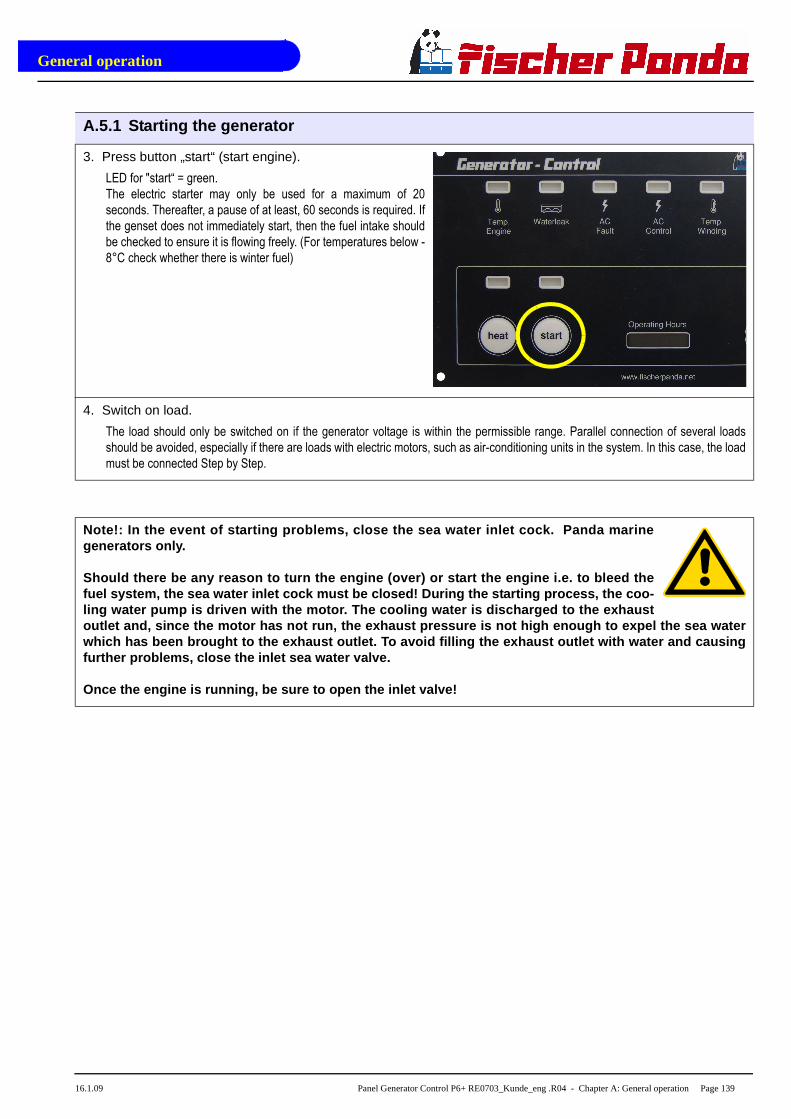
General operation
16.1.09 Panel Generator Control P6+ RE0703_Kunde_eng .R04 - Chapter A: General operation Page 139
3. Press button „start“ (start engine).
LED for "start“ = green.
The electric starter may only be used for a maximum of 20
seconds. Thereafter, a pause of at least, 60 seconds is required. If
the genset does not immediately start, then the fuel intake should
be checked to ensure it is flowing freely. (For temperatures below -
8°C check whether there is winter fuel)
4. Switch on load.
The load should only be switched on if the generator voltage is within the permissible range. Parallel connection of several loads
should be avoided, especially if there are loads with electric motors, such as air-conditioning units in the system. In this case, the load
must be connected Step by Step.
Note!: In the event of starting problems, close the sea water inlet cock. Panda marinegenerators only.
Should there be any reason to turn the engine (over ) or start the engine i.e. to bleed thefuel system, the sea water inlet cock must be close d! During the starting process, the coo-ling water pump is driven with the motor. The cooli ng water is discharged to the exhaustoutlet and, since the motor has not run, the exhaus t pressure is not high enough to expel the sea wate rwhich has been brought to the exhaust outlet. To av oid filling the exhaust outlet with water and causi ngfurther problems, close the inlet sea water valve.
Once the engine is running, be sure to open the inl et valve!
A.5.1 Starting the generator
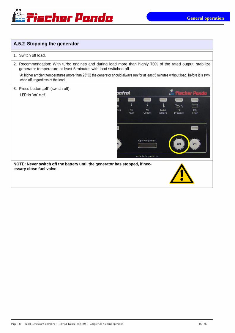
General operation
Page 140 Panel Generator Control P6+ RE0703_Kunde_eng.R04 - Chapter A: General operation 16.1.09
A.5.2 Stopping the generator
1. Switch off load.
2. Recommendation: With turbo engines and during load more than highly 70% of the rated output, stabilizegenerator temperature at least 5 minutes with load switched off.
At higher ambient temperatures (more than 25°C) the generator should always run for at least 5 minutes without load, before it is swit-
ched off, regardless of the load.
3. Press button „off“ (switch off).
LED for "on“ = off.
NOTE: Never switch off the battery until the genera tor has stopped, if nec-essary close fuel valve!

General operation
16.1.09 Panel Generator Control P6+ RE0703_Kunde_eng .R04 - Chapter A: General operation Page 141
A.6 Automatic adapter - option
Fischer Panda Art. No. 21.02.02.016H
Fig. A.6-1: Panel 21.02.02.009H with Automatic adapter 21.02.02.016H
Function:
The automatic adapter RE0704 extends the generator control panel P6+ with an automatic input. A potential-freecontact can be attached to this input. If this contact is closed, then the generator, which is attached to the genera-tor control panel P6+, is started automatically. If the contact is opened, then the generator is stopped automati-cally.
The automatic starting procedure consists of pre-heating (heat) and operating the starter (start). It can be againaborted at any time by opening the contact at the automatic input.
For automatic stopping (stop) the output “Fuel pump” (clamp 9 generator control panel) is switched off. The timefor the automatic stop procedure can be terminated only by switching off generator control panel prematurely.
The times for “heat”, “start” and “stop” are separately adjustable (see below).
The additional automatic adapter switched on and off using the generator control panel with its push buttons “on”and “off”.
If the contact at the automatic input is connected, while the generator control panel is switched on, then the auto-matic starting procedure is carried out.
If the current supply is attached or switched on using the generator control panel, while the contact of the automa-tic input is closed, then the automatic starting procedure won´t be carried out, because the generator controlpanel is always switched off after attaching the current supply (generator the control panel must have been sepa-rate from the current supply for at least 60s).
01
02
03
01. Main terminals02. Automatic adapter 21.02.02.016H03. 8-pole DIP-switch

General operation
Page 142 Panel Generator Control P6+ RE0703_Kunde_eng.R04 - Chapter A: General operation 16.1.09
The mechanism entrance:
With (-) characterized connection is connected to GND.
With (+) characterized connection is the input.
The input is connected through a resistance to 12V (with 24V-operated internally generated). If the two connec-tions are short circuited over a potential-free contact, then the input current flows.
To be considered for an electronic contact the low input current and the polarity is to be selected.
The high input current is to be selected for an electromechanical contact.
The input is debounced (delay time approx.1s).
On the input an external voltages must not be set.
Data:
Parameter Information
Operation voltage The automatic adapter power is supplied via the generator control panel P6+. Thesame absolute maximum ratings obtain as with the generator control panel P6+.
Operation temperature The same absolute maximum ratings obtain as with the generator control panelP6+.
Proper power consumption 10mA - 20mA
Tolerance of times ± 10%
8-pole DIP-switch S1 settings (S1.1 to S1.8):
standard S1.1 S1.2 S1.3 S1.4 S1.5 S1.6 S1.7 S1.8
Heat-time
2,5s OFF OFF
5s ON OFF
10s X OFF ON
20s ON ON
Start-time8s X OFF
16s ON
Stop-time
16s OFF OFF
32s X ON OFF
64s OFF ON
128s ON ON
Operation-modeNormal X OFF
Test (all times over 16) ON
Input current 1,25mA OFF
7mA X ON
Fig. A.6-2: Settings
Attention:
The automatic adapter must only be used together wi th a device. The star-ter should only be switched on when the generator s tationary (shut-down)!

General operation
16.1.09 Panel Generator Control P6+ RE0703_Kunde_eng .R04 - Chapter A: General operation Page 143
A.6.1 Terminal connections
Connection for the automatic adapter X2 (row with odd pin numbers // I/O viwe from operating panel)
Pin-no. Pin-name I / O Description
1 VBF O Current supply + (operation voltage behind fuse)
3 GND O Current supply - (ground)
5 VBFS O Current supply + switched (voltage Pin 1, with panel switched on)
7 12V O Current supply + switched, at 12V-operation over closed soldered jumper J101 connected withVBFS (at optional 24V-operation: VBFS over internal voltage regulator at 12,9V regulated)
9 GND O Current supply - (ground)
11 GND O Current supply - (ground)
13 /Heat-signal I Heat is active, if the input is switched to GND
15 /Start-signal I Start is active, if the input is switched to GND
17 GND O Current supply - (ground)
19 GND O Current supply - (ground)
21 GND O Current supply - (ground)
23 GND O Current supply - (ground)
25 GND O Current supply - (ground)
27 /Stop-signal I The Fuel pump signal is switched off, as long as the input is switched to GND, (also when star-ting)
29 FP-Int O Fuel pump signal internally, decoupled over diode from external signal
31 /Fault-signal O Output is switched to GND, if an error is present (inputs 3, 4, 5, 11 and 12, if configured andgenerally for 2s, after switching on the panel)
33 GND O Current supply - (ground)
Fig. A.6.1-1: Terminal connections automatic adapter

General operation
Page 144 Panel Generator Control P6+ RE0703_Kunde_eng.R04 - Chapter A: General operation 16.1.09
A.7 Master-Slave adapter - option
Fischer Panda Art. No. 21.02.02.015H 12V-version
Fig. A.7-1: Panel 21.02.02.009H with master-slave adapter 21.02.02.015H
Fischer Panda Art. No. 21.02.02.01H 24V-version
Fig. A.7-2: Panel 21.02.02.012H with master-slave adapter 21.02.02.015H
01
02
01. Main terminals02. Master-slave adapter 21.02.02.015H
01
02
01. Main terminals02. Master-slave adapter 21.02.02.015H

General operation
16.1.09 Panel Generator Control P6+ RE0703_Kunde_eng .R04 - Chapter A: General operation Page 145
With the Master-Slave-Adapter RE0706 two Generator Control Panels P6+ RE0703 can be connected to aMaster-Slave-Combination. In addition on each Generator Control Panel P6+ an Master-Slave-Adapter RE0706is installed. The Generator Control Panel P6+ is interconnected by the 14pole connecting terminals on theMaster-Slave-Adapters 1:1. The Master-Panel is hereby defined when the generator is connected to the mainconnector. Thus, the main connector of the Slave-Panel should not be occupied (unconnected).
The solder jumpers on the Master-Panel have to be coded in the same manner as for a Master-Panel without aSlave-Panel as in normal operation. The solder jumpers on the Slave-Panel are coded as for slave operation(please see the appropriate adjustment pages for the Generator Control Panel P6+ RE0703).
The Master-Panel and Slave-Panel are identical, and only differs as a result of the coding. Both Master-Slave-Panels are also identical.
Terminal Connections:
X2: (14polig, 21 - 34) master Slave connection (1:1 wire)
X3: (2polig, 35 - 36) 35: Panel on signal of the Generator Control Panel P6+ RE0703
36: Error signal of the Generator Control Panel P6+ RE0703
The Panel-ON-Signal is active when the panel is switched on.
The error signal is so long active, as the panel recognizes an error, which must lead to switching the generator off.
The output voltage corresponds to the operating voltage of the Generator Control Panel P6+ less 0,7V - 1,4V.Each output has a free wheeling diode which short circuits externals voltage supplies under 0V and a decouplingdiode which decouples the circuitry from external power feeding.
Fuse:
A 0,8AT fuse must be installed on the Master-Panel.
A.7.1 Terminal connections
Terminal X2 ( IN/OUT from view Master-Opearating-Panel)
Pin-No. Pin-name IN / OUT Description
21 VBF O Current supply + (operation voltage behind fuse 12Vdc or 24Vdc depending on system)
22 GND O Current supply - (ground)
23 ON-Signal I / O Panels are switched on, if the connection is switched using a push button (on master or slave)to VBF
24 OFF-Signal I / O Panels are switched off, if the connection is switched using a push button (on master or slave)to VBF
25 /Heat-Signal I / O Heat is active, if the connection is switched over a push button (on master or Slave) to GND
26 /Start-Signal I / O Start is active, if the connection is switched over a push button (on master or Slave) to GND
27 LED-T-Engine O Output for LED T-Engine on the Slave panel, is switched to GND, if the LED is illuminated
28LED-Water-leak (ReplaceAirfilter)
O Output for LED Waterleak on the Slave panel, is switched to GND, if the LED is illuminated
29 LED-Oil-Press O Output for LED Oil-Press on the Slave panel, is switched to GND, if the LED is illuminated
30 LED-AC-Fault(Fuel Level) O Output for LED AC-Fault on the Slave panel, is switched to GND, if the LED is illuminated
Fig. A.7.1-1: Terminal connections terminal X2 (IN/OUT from the view of the master-control-panel)

General operation
Page 146 Panel Generator Control P6+ RE0703_Kunde_eng.R04 - Chapter A: General operation 16.1.09
31 LED-T-Win-ding O Output for LED T-Winding on the Slave panel, is switched to GND, if the LED is illuminated
32 DC-Control O Output for LED DC-Control-display on the Slave panel. The DC control signal is ground through1:1.
33 AC-Control Output for LED AC-Control-display on the Slave panel. The AC control signal is ground through1:1.
34 VBFS O Current supply + switched (otherwise like 21, VBF)
The use of these connections for other purposes, other than the master-slave connection of two generator controlpanels, is generally forbidden. In individual cases, after consultation and clarifying the technical details, a releasefor another use can, if technically possible, be allowed.
Terminal X3
Pin-No. Pin-name IN / OUT Description
35 Panel ON O With panel (ON/OFF) switched voltage of clamp X2.1 (VBF). (Consider notes 1-4)
36 Error O Output is switched on, if a ceitical error is present. (Consider notes 1-4)
Fig. A.7.1-2: Terminal connections terminal X3
Notes:
1. Power rating of the output: max. 0,5A in continuous operation and briefly 1,0A.
2. The supply of all output currents may not exceed (less 0,2A power consumption) the rated current of the safetydevice of the control panel.
3. The output has a free wheeling diode, which short circuit negative voltages (related to GND).
4. The output has a Z-diode, which prevents an overvoltage (related to GND) into the output.
A.7.2 Configuration and adjustment
Configuration and setting sheet KE05
Standard Jumperung for use as Slave-Panel in connection with two Master-Slave-Adapters RE0706 and aGenerator Control Panel P6+ RE0703 as Master-Panel. Panel only for 12V-Betrieb.
The safety device is installed with the value 0,63AT.
The circuit parts for 24V-operation are not equipped.
Fig. A.7.1-1: Terminal connections terminal X2 (IN/OUT from the view of the master-control-panel)

General operation
16.1.09 Panel Generator Control P6+ RE0703_Kunde_eng .R04 - Chapter A: General operation Page 147
Jumper Status Conf. Description
J1 closed during operation of the start button heat is along-operated
open XM Function deactivated
J3
1-2 Dynamo excitation resistor 68R is switched on with Fuel-Pump (1)
2-3 Dynamo excitation resistor 68R is switched on with Panel-ON (1)
open XM Dynamo excitation resistor is deactivated
J101 closed M 12V - operation
open M 24V - operation (not possible)
J201 1-2 T-Engine-input, for contact, which opens in case of error (2)
2-3 XM T-Engine-input, for contact, which closes in case of error (2)
J202 1-2 Water leak-input / Replace air filter, for contact, which opens in case of error (2)
2-3 XM Water leak-input / Replace air filter, for contact, which closes in case of error (2)
J203 1-2 Oil-Press-input, for contact, which opens in case of error (2)
2-3 XM Oil-Press-input, for contact, which closes in case of error (2)
J204 1-2 AC-Fault-input / Fuel level, for contact, which opens in case of error (2)
2-3 XM AC-Fault-input / Fuel level, for contact, which closes in case of error (2)
J205 1-2 T-Winding-input, for contact, which opens in case of error (2)
2-3 XM T-Winding-input, for contact, which closes in case of error (2)
J206 1-2 M Input Water leak has red LED and switches off
2-3 M Input Water leak has yellow LED and does not switch off
J207 1-2 M Input AC-Fault has red LED and switches off
2-3 M Input AC-Fault has yellow LED and does not switch off
J208 1-2 M DC-Control-Signal (-) = OK dynamo 12V at Kubota Z 482 / D 722 engines
2-3 M DC-Control-Signal (+) = OK three-phase DC-alternator
J2091-2 M DC-Control-Signal (-) = OK dynamo 12V at Kubota Z 482 / D 722 engines
2-3 M DC-Control-Signal (+) = OK three-phase DC-alternator
J210 closed Input AC-Fault has Pull-Up-current ≥10mA
open XM Input AC-Fault has Pull-Up-current ≥2,5mA
Fig. A.7-1: Settings of soldered jumper for this configuration (column Conf.)
The solder jumpers are marked on the printed circuit board (with jumper no. and at three-part solder jumper withsoldering surface no.)
X = Jumper must be so set
XM = Jumper, function must be so set on the master panel is selected
M = Jumper must be set exactly the same, as on the master panel,
(1): Equivalent resistance for load control lamp e.g. for use with three-phase alternator also integrated automaticcontroller of Bosch. The resistance value is 68Ω 3W, i.e. only for 12V.
(2): A closed contact switches the appropriate input to GND.

General operation
Page 148 Panel Generator Control P6+ RE0703_Kunde_eng.R04 - Chapter A: General operation 16.1.09
Configuration and setting sheet KE06
Standard jumpering for use as Slave-Panel in connection with two Maste-Slave-Adapters RE0706 and a Genera-tor Control Panel P6+ RE0703 as Master-Panel. Panel for 24V-operation. (over attitude of solder jumper J101alternatively 12V-operation is possible)
The safety device is installed with the value 0,63AT.
The circuit parts for 24V-operation are not equipped.
Jumper Status Conf. Description
J1closed during operation of the start button heat is along-operated
open XM Function deactivated
J3
1-2 Dynamo excitation resistor 68R is switched on with Fuel-Pump (1)
2-3 Dynamo excitation resistor 68R is switched on with Panel-ON (1)
open XM Dynamo excitation resistor is deactivated
J101closed M 12V - operation
open M 24V - operation
J2011-2 T-Engine-input, for contact, which opens in case of error (2)
2-3 XM T-Engine-input, for contact, which closes in case of error (2)
J2021-2 Water leak-input / Replace air filter, for contact, which opens in case of error (2)
2-3 XM Water leak-input / Replace air filter, for contact, which closes in case of error (2)
J2031-2 Oil-Press-input, for contact, which opens in case of error (2)
2-3 XM Oil-Press-input, for contact, which closes in case of error (2)
J2041-2 AC-Fault-input / Fuel level, for contact, which opens in case of error (2)
2-3 XM AC-Fault-input / Fuel level, for contact, which closes in case of error (2)
J2051-2 T-Winding-input, for contact, which opens in case of error (2)
2-3 XM T-Winding-input, for contact, which closes in case of error (2)
J2061-2 M Input Water leak has red LED and switches off
2-3 M Input Water leak has yellow LED and does not switch off
J2071-2 M Input AC-Fault has red LED and switches off
2-3 M Input AC-Fault has yellow LED and does not switch off
J2081-2 M DC-Control-Signal (-) = OK dynamo 12V at Kubota Z 482 / D 722 engines
2-3 M DC-Control-Signal (+) = OK three-phase DC-alternator
J2091-2 M DC-Control-Signal (-) = OK dynamo 12V at Kubota Z 482 / D 722 engines
2-3 M DC-Control-Signal (+) = OK three-phase DC-alternator
J210closed Input AC-Fault has Pull-Up-current ≥10mA
open XM Input AC-Fault has Pull-Up-current ≥2,5mA
Fig. A.7-2: Settings of soldered jumper for this configuration (column Conf.)

General operation
16.1.09 Panel Generator Control P6+ RE0703_Kunde_eng .R04 - Chapter A: General operation Page 149
The solder jumpers are marked on the printed circuit board (with jumper no. and at three-part solder jumper withsoldering surface no.)
X = Jumper must be so set
XM = Jumper, function must be so set on the master panel is selected
M = Jumper must be set exactly the same, as on the master panel,
(1): Equivalent resistance for load control lamp e.g. for use with three-phase alternator also integrated automaticcontroller of Bosch. The resistance value is 68Ω 3W, i.e. only for 12V.
(2): A closed contact switches the appropriate input to GND.

General operation
Page 150 Panel Generator Control P6+ RE0703_Kunde_eng.R04 - Chapter A: General operation 16.1.09

Measurements
16.1.09 Panel Generator Control P6+ RE0703_Kunde_eng .R04 - Chapter B: Measurements Page 151
B. Measurements
B.1 Hole pattern
Fig. B.1-1: Hole pattern
1 1
2 2
3 3
4 4
5 5
6 6
AA
BB
CC
DD
Zu
st.
Än
de
run
ge
nD
atu
mN
am
e
Da
tum
Na
me
Be
arb
.
Ge
pr.
No
rm.
Ma
ßst
ab
:
Ma
teri
al:
Art
ike
l Nr.
:
Ge
wic
ht:
Ers
atz
für
Ers
etz
t d
urc
h
Bla
tt
Pa
ne
l Gen
era
tor
Co
ntr
ol
06
.03
.20
07
jsch
ae
fers
1 A3
Ott
o-H
ahn
-Str
. 3
2-3
4
D-3
31
04
Pad
erb
orn
T
el.:
(0
52
54
) 9
20
2-0
Fa
x (0
52
54)
85
72
4
info
@fis
cherp
and
a.d
e
ww
w.f
isch
erp
an
da.d
e
Allg
em
ein
tole
ran
zen n
ach
D
IN I
SO
27
68
-mK
Ha
lbze
ug
:
Sch
utz
verm
erk
na
ch
DIN
34
be
ach
ten
!
2D
Ze
ich
nun
gs
Nr.
70
67
e0
1
Q:\
Ze
ichn
ung
en\7
06
7e0
1.id
w
Alle
nic
ht
be
ma
ßte
n F
ase
na
=0
,5 m
m25
10519
595
18
53,5
4x
185
95
88
17
7
Ski
zze f
ür
Lo
chbild
layo
ut fo
r hole
patt
ern
87
17
5
21
.02
.02
.00
9H

Measurements
Page 152 Panel Generator Control P6+ RE0703_Kunde_eng.R04 - Chapter B: Measurements 16.1.09
Intentionally Blank