Embed Size (px)
Citation preview
1
EXHIBIT “A”
Maricopa Community College District
Energy Management System
Technical Guideline
Revision B
February 16, 2017
EMS TECHNICAL GUIDELINE Maricopa Community College District, February 16, 2017
2
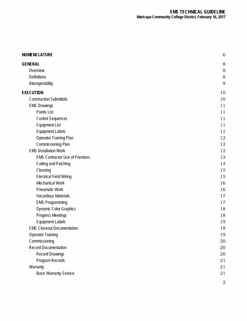
NOMENCLATURE 6
GENERAL 8 Overview 8 Definitions 8 Interoperability 9
EXECUTION 10 Construction Submittals 10 EMS Drawings 11
Points List 11 Control Sequences 11 Equipment List 11 Equipment Labels 11 Operator Training Plan 12 Commissioning Plan 12
EMS Installation Work 12 EMS Contractor Use of Premises 13 Cutting and Patching 14 Cleaning 15 Electrical Field Wiring 15 Mechanical Work 16 Pneumatic Work 16 Hazardous Materials 17 EMS Programming 17 Dynamic Color Graphics 18 Progress Meetings 18 Equipment Labels 19
EMS Closeout Documentation 19 Operator Training 19 Commissioning 20 Record Documentation 20
Record Drawings 20 Program Records 21
Warranty 21 Basic Warranty Service 21
EMS TECHNICAL GUIDELINE Maricopa Community College District, February 16, 2017
3
Service Contract 21 Base Services 21 Additional Time and Material (T&M) Services 22
HARDWARE 24 Hardware Functional Requirements 24
Local Host Station (LHS) 24 BACnet Building Controller (B-BC) 24 BACnet Advanced Application Controllers (B-AAC) 24 BACnet Application Specific Controllers (B-ASC) 25 Input/Output Point Capabilities 26
Analog Inputs (AI) 26 Analog Outputs (AO) 26 Digital Inputs (DI) 27 Digital Outputs (DO) 27 Totalizer Inputs (TI) 27
Instrumentation and Actuator Requirements 27 Temperature Sensors 28 Relative Humidity Sensors 29 Flow Sensors 29 Pressure Sensors 30 Electric to Pneumatic Transducers 30 Pneumatic to Electric Transducers 30 Valves and Actuators 30 Damper Actuators/Motors 31 Electrical Power and Current Transducers 31 Current Transducers 31 Current Switches 31 Ambient Light Sensors 32
Local Area Network (LAN) 32 Inter-Campus Connectivity 32
SOFTWARE 32 Software Functional Requirements 32
Operating System 33 Operator Interface 33
Password Access Control 33 Host Station Software 33
EMS TECHNICAL GUIDELINE Maricopa Community College District, February 16, 2017
4
System Access and Control 33 System Configuration 34 Standard Reports 34 Trend Logging 35 Report Generator 36 Graphical Report Generator 36 Dynamic Color Graphics 37 Maintenance Management 38 Remote B-AAC and B-ASC Configuration 38 Host Bootstrap Program 39
Custom Programming 39 Programming Language 39 Mathematical and Logical Functions 39
Direct Digital Control 40 DDC Control Loops 40 DDC Functions 40 PID Control Loop Tuning 40 Automated PID Control Tuning 41
Application Programs 41 Scheduled Start/Stop 41 Optimum Start/Stop 42 Temperature Override (Night Setback) 42 Supply Air Temperature Reset 42 Variable Air Volume Control 42 Terminal Box Control 43 Temperature Economizer and CO2 Control 43 Electric Heat Demand Limiting 44 Chiller Plant Optimization 44 Chiller System Control 44 Cooling Tower Control 46 Chilled Water Temperature Reset 47 Secondary CHW Pump Control 47 Primary CHW Pump Control 48 Hydronic Economizer Control 48 Power Loss Recovery 49 Heating and Domestic Hot Water System Control 49 Lighting Control 49
EMS TECHNICAL GUIDELINE Maricopa Community College District, February 16, 2017
5
Duty Cycling 50 Auxiliary Fire Alarm Monitoring and Annunciation 50
EMS Failure Modes 50 Last Command (C) 50 High Value (H) and Low Value (L) 51 On/Open (O) and Off/Closed (F) 51 Local Loop (N) 51
EMS Alarm States 51 Safety Alarm 51 Equipment Alarm 52 Maintenance Alarm 52 High and Low Limit Alarms 52 Run Time Alarm 52
System Response 53 Controller 53 Local Area Network 53 Local Host Access 53
ALARMING 53 Alarm Annunciation 53
Notification System 53
EMS TECHNICAL GUIDELINE Maricopa Community College District, February 16, 2017
6
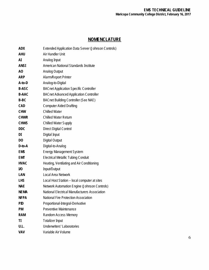
NOMENCLATURE
ADX Extended Application Data Server (Johnson Controls) AHU Air Handler Unit AI Analog Input ANSI American National Standards Institute AO Analog Output ARP Alarm/Report Printer A-to-D Analog-to-Digital B-ASC BACnet Application Specific Controller B-AAC BACnet Advanced Application Controller B-BC BACnet Building Controller (See NAE) CAD Computer Aided Drafting CHW Chilled Water CHWR Chilled Water Return CHWS Chilled Water Supply DDC Direct Digital Control DI Digital Input DO Digital Output D-to-A Digital-to-Analog EMS Energy Management System EMT Electrical Metallic Tubing Conduit HVAC Heating, Ventilating and Air Conditioning I/O Input/Output LAN Local Area Network LHS Local Host Station – local computer at sites NAE Network Automation Engine (Johnson Controls) NEMA National Electrical Manufacturers Association NFPA National Fire Protection Association PID Proportional-Integral-Derivative PM Preventive Maintenance RAM Random Access Memory TI Totalizer Input U.L. Underwriters' Laboratories VAV Variable Air Volume

EMS TECHNICAL GUIDELINE Maricopa Community College District, February 16, 2017
7

EMS TECHNICAL GUIDELINE Maricopa Community College District, February 16, 2017
8
1. GENERAL
1.1. OVERVIEW This Guideline defines the minimum hardware, software and functional performance requirements of an integrated computer-based Energy Management System (EMS) to be installed and/or expanded at the campuses of the Maricopa Community College District (District), Maricopa County, Arizona. Presently, there are multiple EMS Vendors that have been accepted by the District. This Guideline does not differentiate between the vendors or their products, nor does it differentiate between what type of project the vendors may be contracted for. Vendors may be selected and utilized based upon their proposal and ability to perform the specific project requirements. Whether the project is new construction, renovation, or expansion, each vendor shall remain responsible for providing a fully functional system, complete with interoperability, programming and graphics as described herein. The EMS shall provide for local and remote access, monitoring and control of HVAC, central plants, air handlers, and other equipment for specific campuses, buildings, systems, and equipment within the district. This EMS Technical Guideline, Engineering Style Guide and specific Project Specifications are complementary descriptions of the current scope of work and are referred to as the Project Documentation. Inclusion of a work requirement in any one portion of the Project Documentation shall be a sufficient definition of the work required. In areas where a conflict may exist in work description of these documents, the more extensive requirement shall apply, at the District’s discretion. Any and all conflicts shall be clearly noted and a request for clarification should be sent to the District Office. Here and throughout the Guideline, the terms "local", "building" and "campus" refer to those aspects of the EMS pertaining to, and/or residing at, individual buildings or group of buildings at a campus. The terms "Field" or "Remote" refers to those aspects of the EMS involving the field installation and/or the hardware associated to specific input/output monitoring and control capabilities. The terms "Central" or "Master" refers to those aspects of the EMS involving multi-campus monitoring and control capabilities. The term "District" refers to Maricopa Community College District and/or it’s specifically assigned representative. The term “Consultant” refers to Maricopa Community College District’s representative of record. The terms "EMS Contractor" or "Contractor" refers to the EMS Contractor/Vendor and any and all subcontractor(s) hired by the EMS Contractor to satisfy the requirements of the Project Documentation. The term "Project Documentation” refers to the EMS Technical Guideline, Engineering Style Guide and specific Project Specifications, along with any associated contract requirements.
1.2. DEFINITIONS Within the Guideline, the following terms and definitions shall apply:
Furnish: To supply and deliver to project site, ready for unloading, unpacking, assembly, installation, etc. Install: Used to describe operations at the project site including unloading, unpacking, assembly, erection, placing, anchoring, applying, working to dimension, finishing, curing, protecting, cleaning and similar operations, as applicable in each instance.

EMS TECHNICAL GUIDELINE Maricopa Community College District, February 16, 2017
9
Provide: To furnish and install, complete and ready for intended use, as applicable in each instance. Section Reference Number: A reference scheme for identification of each requirement of this EMS Guideline. The Section Reference Number is to be used by the EMS Contractor in completing the Guideline Compliance Document due at time of Proposal.
Controller: Any microprocessor based EMS component capable of executing EMS control functions inclusive of BACnet Advanced Application Controllers (B-AAC), BACnet Application Specific Controllers (B-ASC), and/or any other similar EMS component. Campus: A building or group of buildings associated with a particular community college, district office or other facility as may be described herein. Pricing Agreement: The latest pricing agreement, including terms and conditions, submitted by the contractors and accepted by the District shall remain in effect for any work performed under this Guideline. District and/or District, FP&D: Refers to the Maricopa Community College District, office of Facilities Planning and Development.
1.3. INTEROPERABILITY The District realizes that EMS products and integration technologies now offer the opportunity to mix and/or combine disparate systems within the District, within a single campus or even within a single building. As such, and in order to maintain the existing EMS investment, each Vendor’s product, installation and programming must adhere to specific interoperable requirements. The District will maintain the current Johnson Controls (JCI) Extended Application and Data Server (ADX) and Local Host Stations (LHS). Any and all expansion and renovation project work will interface and interoperate with the ADX through the BACnet connection of a JCI Network Application Engine (NAE), which is the only District accepted BACnet Building Controller (B-BC). No third party, proprietary devices will be accepted. Where NAEs are not currently installed, or where NAE distance or loads are a constraint, the EMS Contractor shall provide, install and program the NAE, and ensure that all functionality of that NAE is accessible through the ADX. All BACnet Advanced Application Controllers (B-AAC), BACnet Application Specific Controllers (B-ASC), and any other devices connected to the JCI NAE (B-BC) will adhere to ASHRAE’s BACnet Data Communication Protocol for Building Automation and Control Networks Standard. The NAE will be programmed by the EMS Contractor such that all discoverable data points within each controller will be visible and manipulable as indicated within each equipments’ specific Protocol Implementation Conformance Statement (PICS). In the event BACnet Advanced Application Controllers (B-AAC), BACnet Application Specific Controllers (B-ASC) or any other equipment connected to the NAE (B-BC) requires proprietary equipment and/or software to gain full access and programming capabilities within the controller, the EMS Contractor shall provide all hardware and software required to do so. The District may be in possession of the required equipment and/or software. However, it is the EMS Contractor’s responsibility to ensure that any specific project does or does not require this equipment, and verify with the District that they do or do not require it. If any specific training is required to utilize the equipment and/or software, the EMS Contractor shall provide adequate training similar to that which is outlined within the training sections below.

EMS TECHNICAL GUIDELINE Maricopa Community College District, February 16, 2017
10
2. EXECUTION a. The EMS Contractor shall provide for all EMS hardware and software, operator input/output devices, relays,
actuators, BACnet Advanced Application Controllers (B-AAC), BACnet Application Specific Controllers (B-ASC), sensors, modems, data transmission media, wiring, electrical power interface/connections, installation labor, installation supervision, calibration, testing, documentation, operator training and warranty service required to provide for a complete, fully functional, and operational EMS.
b. The EMS Contractor shall provide and install an EMS which fulfills the requirements of the Project Documentation for all proposed scopes of work. The Input/Output point requirements and associated control schematics for the scopes of work are summarized within the Input/Output (I/O) Point Summary Tables of the Project Specification and will be developed for each project.
c. The scopes of work shall include all requirements addressed in this Guideline unless specifically noted otherwise. d. Existing points are any EMS equipment, sensors or related wiring which may exist at a particular building which are
directly and solely associated with the present scope of work. This equipment is referenced in the Input/Output Point Summary Tables and denoted by the letter designation associated with the manufacturer and/or model of the equipment. Equipment designated as existing may or may not be wired or pneumatically piped to a controller. Such equipment, wiring or raceway may be utilized by the EMS Contractor in meeting the Project Specification.
e. It shall be the responsibility of the EMS Contractor to verify the installation of such equipment and to assess the operational compatibility of any existing equipment with the Contractor's EMS product line and the requirements of this Guideline. If such existing equipment is not compatible with the Contractor's EMS product line or does not meet the requirements of this Guideline, it shall be the Contractor's responsibility to provide all new equipment, modifications and labor required to meet the requirements of the Project Specification.
f. It is the District's desire that the EMS Contractor utilize existing EMS components, wiring, raceways and pneumatic signal lines to the greatest extent possible in order to provide a cost-effective and specification compliant EMS installation. However, the District desires that all EMS work results in an EMS installation comprised of “current generation” B-AAC’s and/or B-ASC’s. Interface to, and/or upgrade of, existing B-AAC’s and/or B-ASC’s that are not current generation products of their respective manufacturers, shall not be acceptable.
g. At the time of proposal, the EMS Contractor may provide, in writing, specific exceptions to the Guideline which are offered in the interest of fostering the District's desire to re-use existing equipment. Existing input sensors may be considered compliant with the instrumentation requirements defined within Section 3.0 of the Guideline unless otherwise noted.
h. The EMS Contractor shall be responsible to warrant and service any such existing points subsequent to interface or termination to the EMS equipment installed as per the current scope of work unless specific exceptions are noted at the time of proposal. The EMS Contractor shall be responsible for the warranty and service in terms of routine maintenance, interface to the EMS, and required calibration of the existing equipment (except valves and actuators) as defined in Section 2.7. The District shall be responsible for any failures, repairs and/or replacements of existing valves and actuators except in the case of negligence or equipment misuse by the EMS Contractor.
2.1. CONSTRUCTION SUBMITTALS a. The EMS Contractor shall deliver four (4) copies of all submittals described within this Section. The submittals
EMS TECHNICAL GUIDELINE Maricopa Community College District, February 16, 2017
11
shall be delivered to Maricopa Community College District, Facilities Planning and Development Department, 2411 W. 14th Street, Tempe, Arizona 85281-6941 (Telephone (480) 731-8230). Each submittal package shall be clearly marked to indicate the MCCD provided project name/and or description also, the MCCD purchase order number, if applicable, and project number shall be clearly indicated on title page. Also to be included with submittals are the scope of work proposal in accordance with the contractor’s approved pricing agreement. Installation work shall not proceed without written submittal approval from the District, regardless if contract is owner-direct or through a general contractor.
b. Partial submittals of any individual project shall not be accepted. Control software implementation, that does not follow currently established District standards and associated improvements, shall not proceed without written submittal approval from District, FP&D.
2.2. EMS DRAWINGS A complete set of system drawings and schematics that define the architecture and installation of the EMS shall be provided. Schematic drawings shall include "one-line" representations of all EMS monitored and/or controlled systems, associated I/O's and complete termination/relay ladder diagrams for all equipment interconnections, including terminal/circuit numbers of existing equipment being interfaced. Additionally, drawings shall clearly indicate all labeling requirements as specified herein. Complete floor plans shall be provided, indicating locations of all installed equipment.
2.2.1. Points List a. A complete list of all points associated with the EMS shall be provided by the EMS Contractor. The Points
List shall be presented in a format that identifies each B-AAC and B-ASC, the points to which it is connected and the input/output device and/or equipment associated with each point. The points list shall also identify the name(s)/description(s), display units and alarm limit(s)/definition for each I/O point. I/O point names shall follow a consistent format for differentiating between building and systems to the greatest extent possible. Point naming conventions shall follow District established standards, with exceptions approved by the District, FP&D.
2.2.2. Control Sequences a. A complete set of control sequences shall be provided by the EMS Contractor, which detail the algorithms to
be implemented by all control and application programs. The Software Descriptions shall be furnished in an English language format that demonstrates the Contractor's understanding and interpretation of the control requirements contained within the Project Documentation. Program inputs and outputs shall be clearly referenced within each Software Description including both physical (hardware) and operator assignable/adjustable (software) setpoints and parameters.
2.2.3. Equipment List a. The EMS Contractor shall provide a complete list and technical specification data (cut-sheets) for all
equipment to be provided. This Equipment List shall include all system components including sensors, actuators, relays, controllers, B-AAC's, B-ASC’s, enclosures, host hardware and associated power supply and communications surge and overvoltage protection equipment. The Equipment List shall include quantities of all equipment to be supplied and shall be segregated by systems.
2.2.4. Equipment Labels a. Equipment labeling descriptions shall follow District established standards, with all exceptions coordinated
EMS TECHNICAL GUIDELINE Maricopa Community College District, February 16, 2017
12
with the District. All labels shall be self-adhering, blue background with black lettering, ½” in width, 30pt in size, Arial font or as otherwise specified. If low tack, thermal print, adhesive-backed labels are used, the labels must be covered with 1 inch wide, clear tape to prevent lifting. All labels to be installed in a neat, professional manner. Each B-ASC device, intermediate device and sensor used above ceiling shall have a label directly below B-ASC device, intermediate device and sensors, affixed to drop-in-ceiling T-bar so as to be legible from a standing position. At a minimum, labeling shall be included on the following: ● All Controller enclosures ● All Controller modules/B-ASC devices and Network Controllers ● Junction box ● Gauges ● Controlled/monitored equipment
2.2.5. Operator Training Plan a. The Operator Training Plan shall detail the procedure the EMS Contractor shall follow to satisfy the operator
training requirements of Section 2.5. The Operator Training Plan shall include an outline of the lesson plans for each of the various classes proposed and the schedule, location, and duration of the classes.
2.2.6. Commissioning Plan a. The EMS Contractor shall submit a Commissioning Plan for District approval. The Commissioning Plan
shall detail the procedures in which each component and application will be tested for compliance to the Project Documentation. Provide a sample of the documentation that will be utilized in the field during the actual commissioning activities.
2.3. EMS INSTALLATION WORK a. The EMS Contractor shall perform all EMS Installation Work in accordance with all local and state ordinances
and codes relevant to the scope of services provided. The EMS to be provided shall be engineered, manufactured, tested, and installed in a manner to satisfy or exceed the requirements of the current editions of NEMA, ANSI, U.L., and NFPA standards including:
● National Electric Code - NFPA 70 ● U.L. Listing 916 - Energy Management Systems ● Uniform Building Code ● Uniform Mechanical Code
b. The EMS Contractor shall be responsible for obtaining any and all permits and/or inspections required for the scope of work provided. The District shall be provided copies of all permits, inspection certificates, or related documents obtained by the EMS Contractor as required for ordinance and/or code compliance and reimbursement for any fees will be made to the Contractor by the District.
c. All work and equipment provided either outside any building structure, penetrating any building structure or otherwise exposed to ambient conditions shall be performed and constructed to provide a weather-tight installation. In addition, all B-AAC's, related EMS components, pneumatic devices and related components shall be contained in fully hinged and latched cabinets which meet or exceed the NEMA Type 1 Standard (for interior applications) NEMA Type 3R Standard (for exterior applications), be of ample size to facilitate installation and service, be clearly labeled to indicate function and service and be located to avoid exposure to rain and/or condensation. Labels shall be black anodized aluminum, or equivalent, and appropriately engraved where
EMS TECHNICAL GUIDELINE Maricopa Community College District, February 16, 2017
13
exposed to weather. d. The EMS Contractor may be permitted to offer EMS product and/or equipment substitutions or alternates from
approved submittals throughout the contract period upon written approval of the District. The EMS Contractor may request the use of such substitutions or alternates to accommodate new products and or improvements of previously approved products that offer comparable benefits or improvement to the EMS design without compromise to the Project Documentation accepted at time of contract award.
e. The EMS Contractor shall be responsible for assessing the operational function and integrity of all existing sensors, damper sets, actuators and other related valves and actuators that may be interfaced to the EMS for the monitoring and/or control functions specified. The EMS Contractor shall notify the District of any inoperable, damaged or malfunctioning valves, damper sets, or actuators at least fourteen (14) calendar days prior to EMS interface to the device. The District shall be responsible for the repair or replacement of such existing valves, damper sets and actuators only. Fire rated penetrations – all penetrations thru fire rated walls, floor or other assemblies shall be properly fire proofed as required by the applicable building codes.
f. The EMS Contractor shall coordinate and verify with HVAC equipment manufacturers any and all internal control circuit modifications and/or connections to be performed to satisfy the Project Documentation and shall clearly indicate such modifications and/or connections on EMS drawings. The EMS Contractor shall not perform any such modifications, connections and/or termination of EMS equipment to any HVAC equipment without receiving written approval from the equipment manufacturer and the District
g. When specified, the EMS Contractor shall be responsible for the complete removal of all existing temperature control equipment (pneumatic and electric), EMS hardware, sensors, associated time-clocks, wiring, field cabinets and conduit not utilized per the current scope of work that have been rendered inoperative or redundant per the current scope of work. Any removal of equipment shall be coordinated with, and may be supervised by, the District. The removed materials and equipment shall remain the property of the District. Removal shall be performed in a neat and professional manner. All resulting openings in ductwork, piping insulation damage, surface finish damage or other equipment damage affected by the removal shall be properly sealed, repaired and/or re-insulated. Removed materials shall be stored on-site and/or disposed of as directed by the District.
h. The requirements for removal of existing temperature control equipment shall be inclusive of all existing conduit, wiring and/or pneumatic tubing only to the degree that the materials are contained in mechanical rooms, central plants, or other similar equipment rooms. Material in plenum areas that have been rendered inoperative and/or redundant per the current scope of work shall be removed. The extent of removal, by contractor, shall be predetermined by District. Further removal of same shall be at the District’s discretion and cost.
i. Floor or ground penetrations shall be left in a re-usable, code compliant manner such that any penetrations can be re-used for future work either by the EMS Contractor or the District.
j. Fourteen (14) days prior to the Contractor’s scheduled work, the Contractor shall report to the District any and all observed malfunctions, safety hazards and/or electrical/mechanical code violations of existing EMS associated equipment and systems. If any hazards and/or violations affect the Contractor’s work schedule, the District shall have those hazards and/or violations repaired and/or remedied within fourteen (14) days. Upon the Contractor’s use of existing EMS, electrical and mechanical equipment and wiring systems, the Contractor shall take full code-compliance responsibility of all equipment or systems to the extent in which the Contractor has affected work as specified herein.
2.3.1. EMS Contractor Use of Premises a. The EMS Contractor shall limit the storage of materials and equipment on-site to specific areas approved by
the District. At no time during the work under the contract shall the EMS Contractor place, or cause to be placed, any material or equipment at any location that would impede or impair access to or from the facilities. Contractor is responsible for cleanliness of work area and notification to M&O department of
EMS TECHNICAL GUIDELINE Maricopa Community College District, February 16, 2017
14
obstructions or adverse conditions prior to start of work. b. The EMS Contractor shall send proper notices, make all necessary arrangements, and perform all services
required in the care and maintenance of building utilities to the extent that these utilities may be affected and/or interrupted by the EMS installation work. The EMS Contractor shall, during the construction period and until final acceptance of the work by the District, assume all responsibility concerning the same for which the District may be liable. Building utilities shall include telephone/telecommunications, electrical service, natural gas, central heating and cooling water and any other utilities necessary for building operation and occupant comfort.
c. It is of paramount importance that the work of the EMS Contractor provide no or limited interference with the normal operation of existing building/campus operations, utility and/or maintenance services. All work affecting building operations, utilities and/or maintenance services shall be coordinated with the District. The EMS Contractor shall perform EMS installation work requiring building operations, utility and/or maintenance service interruption during evenings and/or weekends as may be reasonably requested by the District without additional cost to the District. The Contractor shall coordinate and schedule any shutdowns or interruptions with the District by notification of at least seven (7) calendar days prior to any interruption during the District’s operating hours. Anytime that contractor is performing owner-direct contracted work, daily check-in/out with campus Maintenance and Operations (or security during off hours or holidays) department is mandatory.
2.3.2. Cutting and Patching a. The EMS Contractor shall be responsible for all cutting, fitting and patching that may be required to
complete the current scope of work and to neatly and professionally integrate the repair into the existing structure and finishes. Any cutting that can result in excessive noise, as to the disruption of classes, shall be done during an unoccupied time of that class or area.
b. The EMS Contractor shall not damage or endanger any portion of existing building operations or any separate contractor’s work by cutting, patching or otherwise altering any work. The EMS Contractor shall not cut or otherwise alter the work or property of the District or any separate Contractor except with the written consent of the District and of such separate Contractor. The EMS Contractor shall not unreasonably withhold from the District or any separate Contractor his/her consent to alter the work required of this contract.
c. The EMS Contractor shall hold any cutting, fitting or patching of new work to the absolute minimum. Should cutting, fitting or patching become necessary, it shall be performed to the minimum requirements as herein stated. Structural elements shall not be cut without the written consent of the District.
d. In all cases, the EMS Contractor shall exercise extreme care in cutting operations, and perform such operations under adequate supervision by competent mechanics skilled in the applicable trades. Openings shall be neatly cut and shall be kept as small as possible to avoid unnecessary damage. Careless and/or avoidable cutting or damaging shall not be tolerated, and the EMS Contractor shall be held responsible for such avoidable or willful damage.
e. All replacing, patching and repairing of all materials and surfaces cut or damaged in the execution of the work shall be performed by experienced mechanics of the several trades involved. Such replacing,
EMS TECHNICAL GUIDELINE Maricopa Community College District, February 16, 2017
15
repairing and/or patching shall be done with the applicable materials, in such a manner that all surfaces so replaced or repaired shall, upon completion of the work, match the surrounding similar surfaces. Additionally, penetrations through any fire rated assembly shall be repaired and/or sealed in such a manner as to meet or exceed the assembly’s original requirements. Fire rated penetrations – all penetrations thru fire rated walls, floor or other assemblies shall be properly fire proofed as required by the applicable building codes.
2.3.3. Cleaning a. During the construction period, the material to be used in the current scope of work shall be kept in an
orderly manner, neatly stacked or piled. The EMS Contractor shall clean-up daily all refuse, rubbish, scrap materials, and debris caused by operations, such that at all times the site of the work shall present a neat, orderly, and professional appearance.
b. The EMS Contractor shall provide for the disposal of all waste products, trash and debris and make necessary arrangements for legal disposal of same off the site. Materials shall never be thrown from windows or other parts of buildings. Waste materials shall be lowered in a controlled manner with as few handlings as possible.
c. The EMS Contractor shall use only cleaning materials, equipment or tools recommended by the manufacturer of the surfaces to be cleaned and on surfaces recommended by the cleaning material manufacturer.
2.3.4. Electrical Field Wiring a. All field wiring within mechanical rooms, central plant buildings, and air handler rooms shall be provided
within EMT conduit or approved equivalent. Furthermore, all field wiring in other than these areas that is exposed or vulnerable to damage shall be provided in EMT conduit or approved equivalent. This requirement applies to all input/output sensors, communications and electrical power supply wiring and cabling. Outdoor field wiring shall be secured in EMT conduit (unless specified otherwise), utilizing appropriate weather tight fittings and installation techniques.
b. All final equipment, panel and device terminations shall be accomplished by EMS factory trained individuals. c. The use of plenum cable within enclosed plenum spaces other than equipment rooms shall be acceptable.
Concealed cabling shall be well supported (no more than six (6) foot spans) and attached to ceiling supports or to the building structure. Cabling shall not be laid directly upon, or remain unsupported on ceiling system support grids or attached to ceiling grid hanger wiring, plumbing, mechanical or electrical pipes or conduits. Plenum cable shall be labeled to indicate service at intervals of not more than twenty-five (25) feet. Cable to be labeled as “Johnson controls” or “EMS Controls” or as approved by District.
d. All field wiring shall be neatly and professionally installed with conduit runs square to room and/or building lines. Wiring/conduit at field devices shall be properly terminated and neatly arranged with minimum 6 inch excess loop provided to allow for future servicing and/or replacement of devices. Junction boxes used by EMS contractor shall be labeled “EMS” in accordance with 2.1.5a.
e. All field wiring shall be properly labeled at each end for easy reference to the identification schematic. All power wiring shall be neatly labeled, at source and load(s), to indicate panel number, voltage and breaker number. Junction boxes used by EMS contractor shall be labeled “EMS” in accordance with 2.1.5a.
EMS TECHNICAL GUIDELINE Maricopa Community College District, February 16, 2017
16
f. The EMS Contractor shall perform all field wiring and circuit connections between the EMS and equipment to be controlled in a manner which provides manual local override operation of the equipment (i.e.: On/Off, Start/Stop, etc.) independent of the EMS. The Contractor shall interface the EMS to the controlled equipment through existing switch devices (i.e.: starters, controllers, relays, switches, etc.) and/or provide new switch devices as required to provide manual local override operation.
g. Electrical service to each B-AAC or B-ASC and/or group of controllers shall be provided by a dedicated circuit clearly marked at its source and at the controller(s) with no other loads attached to the circuit. The location of the breaker shall be clearly identified in each controller serviced by it. If a spare circuit is not available within the electrical breaker panel, the District shall reimburse the EMS Contractor for providing equipment and labor necessary to supply a dedicated controls circuit. B-AAC's or B-ASC’s controlling only packaged air conditioning equipment and VAV boxes with reheat may be powered directly from the packaged unit or VAV reheat control circuits. A typed description of all loads served is required at the source breaker and at each load termination to indicate service (panel), voltage and breaker source.
h. The EMS Contractor shall perform all field wiring and circuit connections between the EMS and HVAC equipment in a manner which neither limits nor circumvents the proper and independent operation and/or function of any and all existing fire and/or smoke control systems, over/under pressurization alarming systems and/or related safety devices.
i. The EMS Contractor shall provide communications required between buildings, utilizing campus fiber optic cables, unless otherwise directed by MCCD district office. Co-ordination with each campus Information Technologies department, for fiber connections, is the responsibility of the EMS contractor.
j. Electrical grounding shall comply with all applicable code requirements. All electrical equipment shall utilize a single point of grounding method that insures a uniform potential on all grounded components.
2.3.5. Mechanical Work a. The EMS Contractor shall be responsible for performing all Mechanical Work required by the Project
Specification. Mechanical Work shall include the installation of valves, automatic valve-motors and actuators. All valve-motors and actuators furnished shall be either electrically or pneumatically actuated as specified and be compatible with the application defined.
b. The EMS Contractor shall furnish and install automatic damper, valve-motors and actuators as specified. The EMS Contractor shall perform Mechanical Work, adjustments and modifications as required to accommodate the motor-damper installations and provide mechanical linkages and other auxiliary components as required to insure a proper and serviceable installation. All mechanical work shall be performed in a neat and professional manner and in compliance with applicable NFPA and U.M.C. requirements and standards.
2.3.6. Pneumatic Work a. All instrument air tubing shall be virgin, non-combustible polyethylene (containing no plasticizer). All tubing
shall be of adequate size and schedule for the intended usage, installed in a neat, professional manner, and be adequately supported.
b. All exposed tubing in mechanical equipment rooms and all other exposed areas shall be installed within metallic conduit or approved alternate. Final terminations to controlled devices may be completed with
EMS TECHNICAL GUIDELINE Maricopa Community College District, February 16, 2017
17
exposed tubing runs no longer than six (6) inches within buildings. Any polyethylene tubing installed outdoors shall not be exposed and where copper tubing is used, proper vibration limiting precautions shall be made. Steps shall be taken as necessary to prevent electrolysis.
c. All tubing shall be number coded on each end and at each junction for easy identification. Additionally, number codes shall be identical to those as shown on the Record Documents (As-builts). Concealed tubing shall be well supported (no more than six (6) foot spans) and attached to ceiling supports or to the building structure. Tubing shall not be laid directly upon ceiling system support grids.
d. Pressure gauges shall be provided on each pneumatic input and output signal of the EMS. The gauges shall read in PSI from 0 - 150 percent of the maximum pressure range of the application and be mounted in metal cabinets with other related pneumatic equipment/devices at each system controlled and/or monitored. Each gauge shall be at least one and one-half (1.5) inches in face diameter, provide a minimum accuracy of + 5 percent at full scale and be neatly labeled to identify its function and the system it serves. Additionally, a port shall be installed adjacent to the gauge for purposes of checking pressures with a calibrated instrument.
e. The EMS Contractor shall be responsible for maintaining high and/or low pressure alarm annunciation and/or safe-guard (cut-off) control of air handlers as provided via existing pneumatic and/or electronic control devices. The EMS Contractor shall either maintain the installation and operation of the existing pressure safe-guard control devices or provide replacements as may be required to maintain existing pressure safe-guard functions while providing currently specified functions.
f. The EMS Contractor shall be responsible for inspecting any and all compressed air systems used in conjunction with the EMS. Any deficiencies shall be reported to the District and upon repair of the system by the District and subsequent re-inspection by the Contractor, the Contractor shall assume full responsibility of the operation and integrity of the system throughout the EMS construction period. Additionally, the Contractor shall report to the District any necessity to upgrade capacities of existing compressed air systems (including air dryers) to accommodate the installation of additional pneumatic devices per the Project Specification.
2.3.7. Hazardous Materials a. The EMS Contractor shall comply with all applicable laws relating to hazardous or toxic materials, including
(without limitation to) asbestos and PCB's. If the EMS Contractor discovers or suspects any such materials on the property, the Contractor shall promptly notify the District and shall cease all work in the area of discovery. The District shall be responsible to identify, remove, monitor, and/or contain any hazardous or toxic materials that would be affected by, and/or exposed to, the current work.
2.3.8. EMS Programming a. The EMS Contractor shall be responsible for all programming and database development required to satisfy
the requirements of the Project Specification. This includes implementation of all control sequences, scaling of analog sensors, entering of point descriptors, generation of dynamic color graphics, setting alarm limits and all other EMS software related functions as specified. All programming for all campuses shall be performed by the same individual as appointed by the Contractor and approved by the District.
b. Reviews of control software development shall be conducted at scheduled progress meetings as required. The reviews shall involve the Contractor's primary programmer for the project, the District and the
EMS TECHNICAL GUIDELINE Maricopa Community College District, February 16, 2017
18
Consultant, as appropriate. The reviews shall serve to address any Contractor questions pertaining to control requirements and/or implementation as well as demonstrating the Contractor's software development status and understanding of all specified control requirements.
c. The EMS Contractor shall perform all database work required to configure the EMS and to display all I/O points in a meaningful and complete manner including English-language descriptors, appropriate engineering units and actual control function. Unless stated otherwise, all values shall be displayed in standard English-Engineering units as appropriate to EMS/HVAC applications (e.g., oF, gpm, psi, % RH, etc.). In addition, all outputs controlling valves and/or dampers shall be configured to display their state as open, closed and/or their percentage open.
d. Database application software shall be compatible with multiple networking software
options (e.g.: Novell Netware™ , DECnet™, LAN Manager™) thereby allowing access to
information and other campus databases. Additionally, the database software shall be
compatible with a Structured Query Language (SQL) and Open Database Connectivity
(ODBC) interfaces for information sharing of campus scheduling, maintenance, and
other database programs.
2.3.9. Dynamic Color Graphics a. When specified, the EMS Contractor shall furnish and install, pre-defined, color graphic displays for all
equipment under EMS monitoring and/or control. At a minimum, individual displays shall be provided to present clear, concise, and complete descriptions of the EMS configuration within each campus, building layout, each air handler system, all central plant equipment and all other equipment/systems included in the EMS installation. Each graphic shall include all associated system input/output points, program parameters and alarms, and permit direct operator control via the color graphic display. All color graphics shall be organized and presented in a tiered penetration format as described herein. Additionally, each graphic shall contain a means of gaining direct access to all other tiers without having to page backward or forward through each individual tier.
b. The graphics shall be in the following tiered method: The first tier shall consist of a campus-wide graphic; The second tier shall consist of the individual building as selected in the prior campus graphic; The third tier shall consist of the individual floor or area as selected in the prior building graphic; The fourth tier shall consist of the individual system of the floor or area as selected in the prior floor or area graphic; The fifth tier shall consist of the previous system graphics’ control parameters and written control sequences in their entirety. Graphics shall illustrate, to-scale, actual campus and building layouts, and clearly identify system configurations and sensor locations
2.3.10. Progress Meetings a. The EMS Contractor shall participate in regularly scheduled progress meetings throughout the construction
period of each project, at intervals determined by District, and at additional meetings as required, unless waived by agreement with the District. The meetings shall be held at the District’s or Consultant’s offices or
EMS TECHNICAL GUIDELINE Maricopa Community College District, February 16, 2017
19
a specific college or campus as directed by the District and be attended by representatives of the District and the primary project coordinator of the EMS Contractor. At each meeting, the EMS Contractor representative shall be prepared to summarize the current installation status and discuss any technical problems encountered.
b. Progress Reports for each project shall be issued in a monthly meeting by the Contractor which shall include an updated schedule which reflects all submittal, programming, installation, start-up, testing, commissioning, training, and acceptance events. The Progress Report shall also describe any technical problems encountered, suggestions for resolution, and prior technical problems resolved. Each Progress Report shall be submitted to the District two (2) days prior to the scheduled meeting.
2.3.11. Equipment Labels a. The Contractor shall provide and mechanically affix all new labels for controlled/monitored equipment and
associated electrical equipment. Labels shall reflect the exact name given to that piece of equipment by the current EMS scope of work using District standard naming conventions. Where exposed to weather, labels shall be black anodized aluminum and appropriately engraved. Labels shall be of identical size, color and material District-wide as is appropriate for ease of equipment identification.
2.4. EMS CLOSEOUT DOCUMENTATION a. For each campus, the EMS Contractor shall provide all manuals containing technical specifications, operating
instructions, installation and removal instructions, programming instructions, maintenance and calibration procedures, and troubleshooting guides for all EMS components provided as per the current scope of work. At a minimum, the EMS components addressed shall include B-AAC's, B-ASC’s, workstation hardware and software, I/O sensors, transducers, transmitters and other associated devices.
b. Provide reports that detail the results of the commissioning performed by the EMS Contractor as per the Commissioning requirements of Section 2.6. At a minimum, the Report shall include all field documents utilized during the commissioning process, and a brief summary report of general findings.
c. Four (4) complete sets of the required documentation shall be provided to the District. Each manual shall be provided in hard cover, loose-leaf type binders and be clearly and professionally titled on both its side and front cover. Each manual shall have a table of contents, index, and tab sheets to divide sections. All manuals shall be delivered to the District prior to commencement of any on-site installation work.
2.5. OPERATOR TRAINING a. When specified, the EMS Contractor shall be responsible to schedule and provide on-site training regarding all
aspects of EMS system operations. On-site training shall be scheduled for no longer than four (4) hours per session, and no more than two (2) sessions per week. Training vouchers for use at corporate training centers may be considered in lieu of on-site training. Amount of hours to be included for training or acceptance of training vouchers shall be determined on a project-by-project basis by District. Off-site training shall be conducted on identical equipment as is installed within the District.
b. At a minimum, the on-site training shall include an overview of the EMS installation provided as per the current scope of work, explanation of all EMS components and functions, explanation of EMS control strategies, instruction on Local Host Station use, data backup procedures, explanation of the set-up and generation of all EMS reports and graphics, description of alarm conditions and acknowledgment procedures, and instruction on system operation..
c. On-site training shall also detail preventive maintenance and operational performance verification procedures for host components, gateways, B-AAC's, B-ASC’s, sensors, transducers and all other equipment provided under
EMS TECHNICAL GUIDELINE Maricopa Community College District, February 16, 2017
20
the current scope of work. At a minimum, maintenance procedure instruction shall include B-AAC and B-ASC troubleshooting and repair, input/output point addition and deletion, verification and calibration of sensors, transducers, output devices, and network communications.
d. The EMS Contractor shall be responsible to provide, at no additional cost to the District (except for travel related expenses) an established educational program that includes professional course(s) as defined herein. Successful completion of the course(s) shall result in the District's attendees being certified as factory trained EMS specialists as well as the award of Continuing Education Units (CEUs). All associated materials, manuals and texts shall be included as part of these courses.
e. Professional courses are to be conducted off-site at a corporate training center (preferably within the metro-Phoenix area). Subject matter shall include, but is not limited to, established class programs offered in at least the following two (2) advanced instruction levels:
f. Level 1: Advanced operator/supervisor courses shall offer instruction regarding campus management of energy, advanced color graphic and report generation, and all additional related subject matter regarding campus energy and EMS management for the full scope of EMS attributes and capabilities provided.
g. Level 2: Complete coverage of advanced EMS programming and configuration instruction including program creation, editing and the highest level of system control management and hardware service.
h. Level 1 instruction shall include a minimum of forty (40) hours of classroom/lab participation for a minimum of four (4) District assigned personnel. Level 2 instruction shall include a minimum of forty (40) hours of classroom/lab participation for a minimum of four (4) District assigned personnel.
2.6. COMMISSIONING a. The EMS Contractor shall commission and document compliance to the Project Documentation of all installed
components, input/output (I/O) points and calibration, EMS control functions, application programs (control sequences), reporting functions, and LHS functionality. Commissioning, or a portion thereof may be witnessed by the District and/or Consultant. The EMS Contractor shall notify the District or Consultant of all upcoming commissioning activities two weeks in advance of any scheduled activities.
b. Commissioning shall include issuance of commands through the Local Host Station (LHS) which shall force all installed controllers to exercise all monitoring and control functions including, but not limited to:
● Monitoring of input/output points ● Execution of application programs ● Generation, issuance, and acknowledgment of alarms
c. Where applicable, LHS testing shall demonstrate all functional capabilities including, but not limited to: ● Operator interface, access and password restrictions ● System access and configuration ● Database management ● Standard reports ● Trend logging ● Custom programming capability ● Color Graphics
2.7. RECORD DOCUMENTATION a. Prior to EMS system acceptance by the District (and release of final retainage by the District), the EMS
Contractor shall provide four (4) complete sets of Record Documentation per campus as described herein.
2.7.1. Record Drawings a. All submittal requirements defined in Section 2.1 shall be inclusive of the requirements of this Section. All
EMS TECHNICAL GUIDELINE Maricopa Community College District, February 16, 2017
21
submittals noted shall be updated and provided as part of the Record Documentation defined herein. b. The EMS Contractor shall provide Record Drawings and Schematics (As-Builts) of the complete EMS
installation for all campuses. The Schematic Drawings shall illustrate the final EMS configuration and input/output point installation for all systems monitored and/or controlled via the EMS. The drawings shall detail the installed locations and routing of all communications (N1 & N2) and sensor wiring/cabling, sensor locations and all other EMS components installed. The Record Drawings shall indicate the location of all field devices (remote to primary HVAC equipment) on "to-scale" floor plans.
c. The EMS Contractor shall provide a single CD-ROM, formatted for IBM compatible computers, containing all As-Built drawings using either Visio® or AutoCad® formats for each project.
2.7.2. Program Records a. The EMS Contractor shall provide complete program descriptions of all control and application software
provided as per the EMS installation. The program descriptions shall include complete source code listings, flow charts and English language explanations of all control/application programs that are associated with equipment control as specified herein.
b. The EMS Contractor shall ensure that all applicable software for all devices is loaded into main operator workstation, for each location, and in the appropriate directory prior to final turnover. Additionally, all software shall be recorded and submitted on a single CD-ROM, formatted for IBM compatible computers.
2.8. WARRANTY a. The EMS installed as part of this project, including all hardware, software, equipment, sensors and wiring shall
be warranted for a period as defined herein. Any EMS defect, deficiency or failure that is identified during this warranty period shall be corrected without cost to the District for either materials or labor, as specified. Additionally, the Contractor shall issue a report to the District as to what work was performed. Warranty (except for existing valves and actuators) shall extend to all existing equipment that has been selected for re-use as determined by District.
2.8.1. Basic Warranty Service a. For a period, as specified, from the date of system acceptance and as may be extended beyond, per MCCD
approval, and per Section 2.0 execution period requirements, the EMS Contractor shall provide Basic Warranty Services without additional cost to the District. Basic Warranty Services shall be provided as defined in Section 2.8.1.
2.9. SERVICE CONTRACT a. A one (1) year Service Contract commencing upon the end of the warranty period shall be submitted to the
District at the time of proposal. The Service Contract shall be either accepted or rejected by the District at the conclusion of the warranty period. The Service Contract shall be renewable on an annual basis at the discretion of the District. The Service Contract shall include cost breakouts for labor and materials for all areas of service proposed.
b. The cost associated with the Service Contract for each year after the first year shall be subject to the same cost provisions of the EMS Price Guarantees.
2.9.1. Base Services a. For no additional cost within the warranty period, the EMS Contractor shall provide the following services to

EMS TECHNICAL GUIDELINE Maricopa Community College District, February 16, 2017
22
the District: ● Maintain current Record (As-Built) Drawings, schematics and program records of the District’s
complete EMS and update as required to reflect all modifications made to the EMS. Four (4) complete up-to-date sets of Record Documentation shall be maintained by the Contractor at the District’s main office and one (1) complete set at each of the campuses of that particular campus. Revised drawings, schematics and Program Records shall be furnished periodically throughout the year as needed to maintain the records and to document all hardware and software modifications implemented by the Contractor.
● Provide specified hours of on-site training, at the manufacturer’s corporate office, or locally at the Contractor’s facility as requested by the District. Travel expenses for District personnel (if any) including transportation, meals and lodging shall be paid by the District. In lieu of on-site training, contractor may provide voucher(s) for training that may be redeemed at Contractor’s training institutions for classes offered in published class catalogs. Training vouchers must be provided directly to MCCD, FP&D.
● Respond to EMS repair and/or service requests within four (4) hours of notification by the District during the District’s normal operational hours.
● Replace and/or repair defective, in-warranty, system components within twenty-four (24) hours of notification. The EMS Contractor shall maintain an appropriate inventory of spare parts at its local office to facilitate this capability.
● Provide EMS support via a virtual connection from the Contractor’s local office. ● Service shall be provided by factory trained personnel directly employed by the local EMS Contractor
and/or representatives of related equipment manufacturers. ● Maintain and support all EMS software provided per the Project Documentation. This support shall
include all host, operating system, application/control, and third party software. ● The Contractor shall furnish a detailed Preventive Maintenance (PM) schedule that itemizes the
specific maintenance requirement of all EMS components. b. In the event any service problem can not be repaired in the time frames described above, it is the
responsibility of the Contractor to implement necessary by-passes, overrides and/or manual control in order to temporarily restore any system to an operating condition. Any such temporary implementation shall be coordinated with the District.
2.9.2. Additional Time and Material (T&M) Services a. The Contractor shall be reimbursed on a time and material basis for the additional, non-warranty related
services identified herein. The costs for these additional services shall be based upon the EMS Price Guarantees defined herein. Payment shall be made for T&M work requested by the District only to the degree that the work is not otherwise required of the Contractor as per the Warranty or Base Service requirements of this Guideline.
● Provide emergency maintenance service within four (4) hours from notification that an EMS fault has occurred. The response time shall be maintained twenty-four (24) hours per day, seven (7) days per week, every day of the year.
EMS TECHNICAL GUIDELINE Maricopa Community College District, February 16, 2017
23
● Replace and/or repair defective out-of-warranty system components within twenty-four (24) hours of notification. The contractor shall maintain an appropriate inventory of spare parts at its local office to facilitate this capability.
b. Following any requested T&M work, the Contractor shall submit a report to the District which indicates all equipment inspected and serviced, the condition of the equipment and associated components, the location of the equipment, the type of service performed, the individuals who performed the repair, which District personnel initiated the requested work, and which District personnel witnessed, checked or verified the completion of the work.
EMS TECHNICAL GUIDELINE Maricopa Community College District, February 16, 2017
24
3. HARDWARE 3.1. HARDWARE FUNCTIONAL REQUIREMENTS The EMS to be installed shall provide automation, control, monitoring and energy management functions as described within the Project Documentation. The EMS installation shall be provided in a configuration and with the necessary equipment and programming to be "stand-alone", distributed control, which does not require communications (other than operator and alarm functions) with the EMS Local Host Station (LHS).
3.1.1. Local Host Station (LHS) a. The Local Host Station (LHS) shall provide for full EMS host functional capability and operator access to its
associated campus as well as the ability to communicate to and from any other campus EMS installations within the District. The LHS shall be based upon an architecture, software and hardware design that shall permit operator access to a final, fully automated, campus and District-wide system.
3.1.2. BACnet Building Controller (B-BC) a. The BACnet Building Controller (B-BC) is the main interface for the building control system. b. The JCI Network Application Engine (NAE) is the only District’s accepted B-BC.
3.1.3. BACnet Advanced Application Controllers (B-AAC) a. The EMS shall utilize intelligent, microprocessor-based, real-time, BACnet Advanced Application
Controllers (B-AAC's). The B-AAC's shall interface monitored sensors and controlled devices to the EMS. An B-AAC shall consist of a single microprocessor-based controller or a master microprocessor controller connected to a sub-network of microprocessor controllers and/or field input/output devices. An B-AAC is further defined as a microprocessor-based interface or gateway between the EMS and any third-party equipment.
b. All controllers and software shall communicate via BACnet using standard BACnet objects and services. All controllers will be certified by the BTL (BACnet Testing Laboratories) as B-ASC (BACnet Application Specific Controllers) or B-AAC (BACnet Advanced Application Controllers).
c. The B-AAC's shall exist on peer-to-peer network. The B-AAC's shall provide fully distributed control independent of the operational status of the ADX. Each B-AAC shall be properly equipped, programmed and installed to provide the following functions:
d. Acquire, process and transmit data through the network to other B-AAC's, BACnet Application Specific Controllers (B-ASC’s), and any host access device.
e. Accept, evaluate and execute commands received via another B-AAC and host access device. f. Record and report the changes of state and/or values of input/output points or pseudo points that are
physically, or through software, identified to any other B-AAC. g. Execute all application programs, calculations and commands via the B-AAC's resident microprocessor
necessary to satisfy the monitoring and control requirements presented within this Guideline and within the Input/Output Point Summaries. All necessary calculations required to achieve this control shall be executed within the B-AAC independent of the LHS. All control strategies performed by the B-AAC shall be both operator definable and modifiable through the LHS.
EMS TECHNICAL GUIDELINE Maricopa Community College District, February 16, 2017
25
h. Perform self-test diagnostics automatically and report malfunctions to the ADX. At a minimum, a report shall be made at:
● failure of any sensor within an B-AAC's data environment ● loss or corruption of the B-AAC's database and/or configuration ● power supply or communications disruption
i. B-AAC’s shall include all point inputs and outputs necessary to perform the specified control sequences. Analog outputs shall be industry standard signals (electric and pneumatic) allowing for interface to a variety of modulating actuators. Controllers utilizing proprietary control signals and actuators shall not be acceptable.
j. If an input point physically associated with a particular B-AAC fails, control dependent upon that input shall continue based upon the most recent data received, established default value, or an operator definable programmed state.
k. B-AAC volatile memory shall be provided with battery backup to sustain that memory, in the event of a power outage, for a minimum of seventy-two (72) hours.
l. Each B-AAC shall be contained within a cabinet that meets or exceeds the NEMA Type 1 Standard. Each cabinet shall be uniquely identified as part of the EMS and appropriately labeled and be master-key locked. Labels shall be plastic or black anodized aluminum and appropriately engraved.
m. The EMS Contractor shall provide a 20 amp duplex receptacle within each B-AAC or immediately adjacent to the B-AAC.
n. Each B-AAC shall be properly equipped to protect itself, other B-AAC’s and the networks to which they are connected from induced voltage and/or current transients and voltage and/or current spikes or under-voltages which may occur at the B-AAC power supply, input/output point connections or communications wiring.
o. All B-AAC's shall be Underwriters' Laboratory (UL) listed against fire and shock hazard as part of an Energy Management System with UL listing number 916. Each B-AAC shall be able to operate in an ambient environment of 32ºF to 135ºF and 10% to 90% Relative Humidity.
3.1.4. BACnet Application Specific Controllers (B-ASC) a. B-ASC’s shall exist on a sub-network or networks of an B-AAC. Each B-ASC shall operate as a stand-
alone controller, performing specified control responsibilities independent of other B-ASC’s or B-AAC’s. All system setpoints, proportional bands, control algorithms, and any other programmable parameters shall be stored such that a power failure of any duration does not necessitate reprogramming. Additionally, the B-ASC shall be programmed by the operator by means of pre-defined and/or pre-structured, “fill-in-the-blank” or graphical interface type software.
b. All controllers and software shall communicate via BACnet using standard BACnet objects and services. All controllers will be certified by the BTL (BACnet Testing Laboratories) as B-ASC (BACnet Application Specific Controllers) or B-AAC (Advanced Application Controllers).
c. Each B-ASC shall be a microprocessor-based, multi-tasking, digital control processor utilizing its own processor, memory, input/output, analog to digital conversion, clock and voltage transient protection devices. The B-ASC shall perform its own limit and status monitoring and analysis to maximize network
EMS TECHNICAL GUIDELINE Maricopa Community College District, February 16, 2017
26
performance by reducing unnecessary communications. d. B-ASC’s shall include all point inputs and outputs necessary to perform the specified control sequences.
Analog outputs shall be industry standard signals (electric and pneumatic) allowing for interface to a variety of modulating actuators. Controllers utilizing proprietary control signals and actuators shall not be acceptable.
e. Each B-ASC shall be properly equipped to protect itself, other B-ASC’s and the networks to which they are connected from induced voltage and/or current transients and voltage and/or current spikes or under-voltages which may occur at the B-ASC power supply, input/output point connections or communications wiring.
f. All B-ASC's shall be Underwriters' Laboratory (UL) listed against fire and shock hazard as part of an Energy Management System with UL listing number 916. Each B-ASC shall be able to operate in an ambient environment of 32ºF to 135ºF and 10% to 90% Relative Humidity.
g. Room sensors associated with B-ASC’s shall, where specified, include a manual setpoint adjustment available to the room occupant. Adjustment range shall be operator definable. Sensor shall also have an override switch built into the sensor face, usable by the room occupant to initiate a schedule override mode where specified.
3.1.5. Input/Output Point Capabilities a. Each B-AAC and B-ASC shall provide the hardware and software required to support an I/O point
configuration of Analog Inputs (AI), Analog Outputs (AO), Digital Inputs (DI), Digital Outputs (DO), and/or Totalizer Inputs (TI). The B-AAC's and B-ASC’s furnished shall provide for all points identified within the Input/Output Point Summary Tables as required to meet the Project Specification. In order to satisfy the point type density requirements, universal input / output capabilities may be utilized.
3.1.5.0. Analog Inputs (AI) a. The B-AAC and B-ASC shall monitor each AI point and perform Analog-to-Digital (A-to-D)
conversion. A-to-D conversion shall be executed with a minimum 12-bit resolution. The ranges of analog inputs shall include at least 4-20 mA, 0-10 Vdc, and assignable functions for use with standard resistance temperature detectors (RTD's) and/or standard thermistors for any AI address.
b. AI capability shall provide common mode noise rejection of 60 dB from 0 to 120 Hz and normal mode noise rejection of 20 dB at 60 Hz from a source impedance of 10,000 ohms. All AI connections shall be provided with surge protection to withstand up to 180 Vac peak input without controller damage.
3.1.5.1. Analog Outputs (AO) a. The B-AAC and B-ASC, based upon digital data received or information processed, shall perform
Digital-to-Analog (D-to-A) conversion and output a true analog signal including 4-20 mA or 0-10 Vdc and other industry standards as required per application. D-to-A conversion shall be performed with a minimum 10-bit resolution. All AO's shall be of a proportional current or voltage type with a minimum incremental resolution of 0.5 percent of the full operating range of the
EMS TECHNICAL GUIDELINE Maricopa Community College District, February 16, 2017
27
actuator or controller to which the AO is interfaced. b. Where required, electronic to pneumatic transducers shall be installed in conjunction with the AO
to provide a pneumatic output compatible with the pneumatic actuator or controller being interfaced to the EMS (e.g.: 0-15psi). Such transducers shall respond to an B-AAC or B-ASC failure or power loss as noted by the Failure Mode on each Input/Output Point Summary Table.
c. Each AO point specified shall be unique to the specific function and/or device identified and shall not be used to provide an analog output to any other device unless specifically noted within the Project Specification or Input/Output Point Summary Tables. All B-AAC and B-ASC AO's shall be able to be interrogated by the LHS to examine their present commanded value or state and configuration.
d. The EMS Contractor shall be responsible to install any protection necessary to prevent damage from compressed air contaminates to installed pneumatic controllers, transducers or devices.
3.1.5.2. Digital Inputs (DI) a. The B-AAC and B-ASC shall accept discrete data indications at any DI point. Such data shall be
interpretable as on/off, open/closed or any other binary condition. Each DI point shall be furnished with surge protection to withstand up to 180 Vac peak input without device failure. DI contacts shall sustain a constant load of 2 amps at 24 Vac without failure.
3.1.5.3. Digital Outputs (DO) a. The B-AAC and B-ASC shall provide discrete outputs capable of both maintained and momentary
contact. Each DO contact shall be capable of either being opened, closed and pulsed closed. Each DO point shall be furnished with surge protection to withstand up to 180 Vac peak without device failure. DO contacts shall be capable of sustaining a constant load of 2 amps at 24 Vac without failure.
b. Each DO shall be capable of either a failed open or closed connection. A failure shall consist of either an B-AAC or B-ASC loss of configuration/database memory or power.
3.1.5.4. Totalizer Inputs (TI) a. The B-AAC and B-ASC shall provide for discrete inputs configurable as pulse accumulator points
at which the controllers shall totalize rates of pulsed inputs up to 20 pulses per second of a minimum pulse-width of 10 milliseconds. TI contacts shall be capable of sustaining a constant load of 2 amps at 24 Vac without failure.
3.2. INSTRUMENTATION AND ACTUATOR REQUIREMENTS a. The EMS Contractor shall furnish and install all instrumentation, actuators, transducers, and sensors as required by
this Guideline and the Input/Output Point Summary Tables. The accuracy and range of sensors vary by application, and are detailed in the following sections. For applications where a specific range has not been specified, the EMS Contractor shall be responsible for proper selection. All applications listed may not be included within the current scope of work. Deviations from specified materials shall be submitted, in writing, to MCCD/FP&D for approval prior to ordering/procuring material.
b. The term "accuracy" as used herein refers to net measurement accuracy from sensor to the B-AAC or B-ASC
EMS TECHNICAL GUIDELINE Maricopa Community College District, February 16, 2017
28
received and/or displayed value. Demonstration of the specified accuracy shall be the EMS Contractor's responsibility as per the acceptance testing requirements of Section 2.6 and the calibration requirements defined herein. The Contractor shall be responsible for incorporating calibration correction equations, offsets and/or slopes into the B-AAC or B-ASC configuration as needed.
c. The Input/Output Point tables and schematic information provided in the project description indicate the points to be monitored and controlled. Actual EMS field installation methods and procedures are the EMS Contractor's responsibility. The Contractor shall also comply with all installation procedures and recommendations of the instrumentation manufacturer(s).
d. For all pipe temperature, flow rate and pressure instrumentation, the EMS Contractor shall be responsible for the repair, seal and refinish of any and all existing pipe insulation and vapor barrier disturbed by the work. Insulation and vapor barrier repair shall be performed in a neat and professional manner. The sensor point of connection/termination shall extend beyond the insulation height. All pipe instrumentation (components and installations) shall withstand at least 125 psi service pressure.
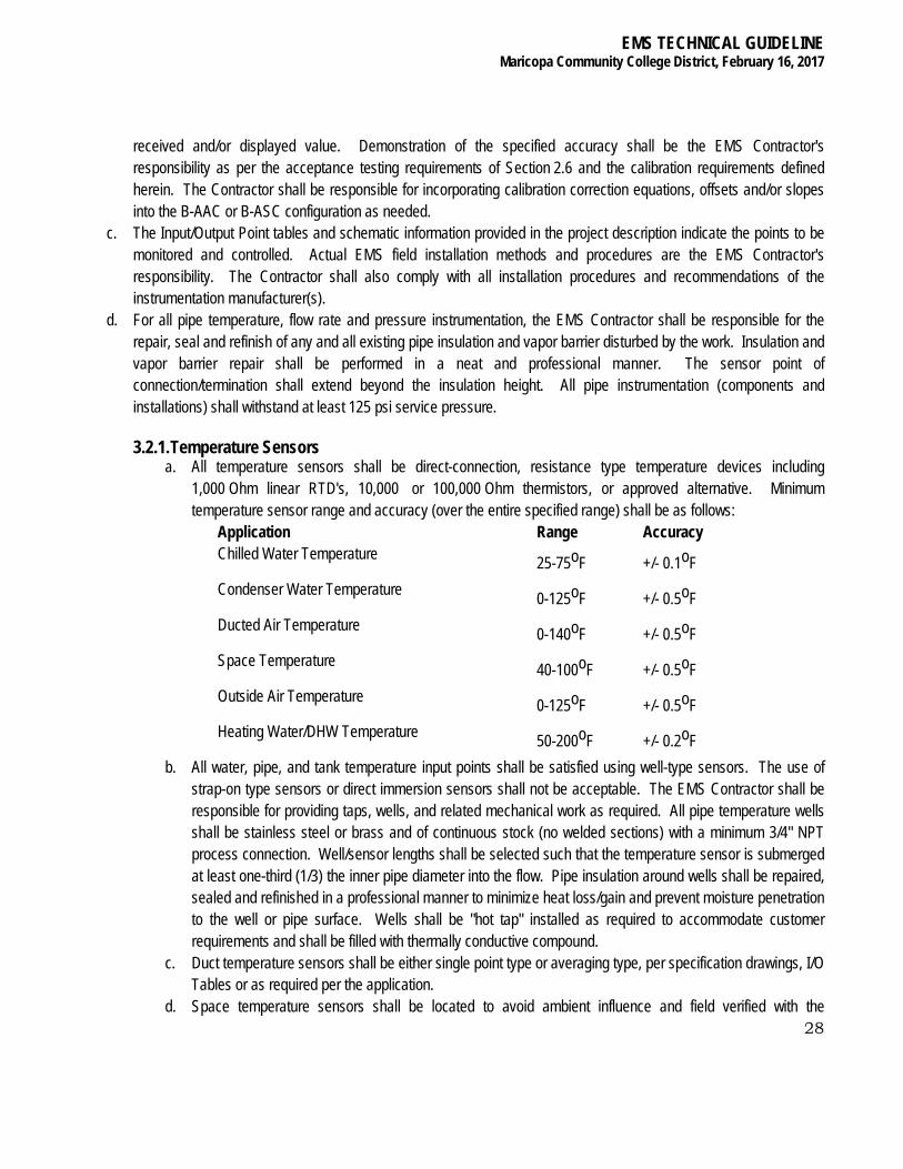
3.2.1. Temperature Sensors a. All temperature sensors shall be direct-connection, resistance type temperature devices including
1,000 Ohm linear RTD's, 10,000 or 100,000 Ohm thermistors, or approved alternative. Minimum temperature sensor range and accuracy (over the entire specified range) shall be as follows:
Application Range Accuracy Chilled Water Temperature 25-75oF +/- 0.1oF Condenser Water Temperature 0-125oF +/- 0.5oF Ducted Air Temperature 0-140oF +/- 0.5oF Space Temperature 40-100oF +/- 0.5oF Outside Air Temperature 0-125oF +/- 0.5oF Heating Water/DHW Temperature 50-200oF +/- 0.2oF
b. All water, pipe, and tank temperature input points shall be satisfied using well-type sensors. The use of strap-on type sensors or direct immersion sensors shall not be acceptable. The EMS Contractor shall be responsible for providing taps, wells, and related mechanical work as required. All pipe temperature wells shall be stainless steel or brass and of continuous stock (no welded sections) with a minimum 3/4" NPT process connection. Well/sensor lengths shall be selected such that the temperature sensor is submerged at least one-third (1/3) the inner pipe diameter into the flow. Pipe insulation around wells shall be repaired, sealed and refinished in a professional manner to minimize heat loss/gain and prevent moisture penetration to the well or pipe surface. Wells shall be "hot tap" installed as required to accommodate customer requirements and shall be filled with thermally conductive compound.
c. Duct temperature sensors shall be either single point type or averaging type, per specification drawings, I/O Tables or as required per the application.
d. Space temperature sensors shall be located to avoid ambient influence and field verified with the
EMS TECHNICAL GUIDELINE Maricopa Community College District, February 16, 2017
29
Consultant prior to installation. The sensor shall be installed in a manner to guard against any external effects that would prevent accurate monitoring of space temperature. Sensor cover colors shall be coordinated with the District prior to installation.
e. Outside air temperature sensor(s) shall be installed in a location with suitable airflow across the sensor and in a continuously shaded location, or mounted with a sun shield. The sensor shall be installed in a manner to guard against any external effects that would prevent accurate monitoring of ambient conditions. The proposed sensor location shall be approved by the Consultant or District prior to installation.
f. All temperature sensors shall be supplied with a manufacturer's and/or supplier's documentation/certification of factory calibration with appropriate results reported. In addition, the EMS Contractor shall perform a calibration validation test for all temperature sensors provided. All temperature sensors shall be calibrated at its average or expected normal operating temperature range.
g. For non-linear, temperature sensors, the sensor shall be submersed in an insulated water bath of nominally the same temperature as to be experienced in the monitored application. The water temperature shall be recorded via the B-AAC/B-ASC and simultaneously via a calibrated reference thermometer of no less than 0.1F resolution and accuracy. A three (3) point calibration shall be performed, with readings recorded at plus/minus fifty (50) percent of the nominal value and appropriate correction offset(s) and/or equations calculated for sensor correction.
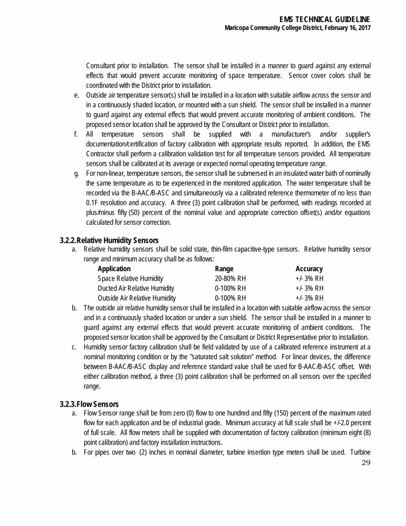
3.2.2. Relative Humidity Sensors a. Relative humidity sensors shall be solid state, thin-film capacitive-type sensors. Relative humidity sensor
range and minimum accuracy shall be as follows: Application Range Accuracy Space Relative Humidity 20-80% RH +/- 3% RH Ducted Air Relative Humidity 0-100% RH +/- 3% RH Outside Air Relative Humidity 0-100% RH +/- 3% RH
b. The outside air relative humidity sensor shall be installed in a location with suitable airflow across the sensor and in a continuously shaded location or under a sun shield. The sensor shall be installed in a manner to guard against any external effects that would prevent accurate monitoring of ambient conditions. The proposed sensor location shall be approved by the Consultant or District Representative prior to installation.
c. Humidity sensor factory calibration shall be field validated by use of a calibrated reference instrument at a nominal monitoring condition or by the "saturated salt solution" method. For linear devices, the difference between B-AAC/B-ASC display and reference standard value shall be used for B-AAC/B-ASC offset. With either calibration method, a three (3) point calibration shall be performed on all sensors over the specified range.
3.2.3. Flow Sensors a. Flow Sensor range shall be from zero (0) flow to one hundred and fifty (150) percent of the maximum rated
flow for each application and be of industrial grade. Minimum accuracy at full scale shall be +/-2.0 percent of full scale. All flow meters shall be supplied with documentation of factory calibration (minimum eight (8) point calibration) and factory installation instructions.
b. For pipes over two (2) inches in nominal diameter, turbine insertion type meters shall be used. Turbine
EMS TECHNICAL GUIDELINE Maricopa Community College District, February 16, 2017
30
insertion meters shall be equivalent to the ONICON F-1200 (dual turbine probe) and installed in accordance with manufacturer's specifications. Meters shall permit isolation, retraction and replacement of the sensor for service without interrupting or affecting the monitored medium.
c. For pipes of two (2) inches in diameter or less, line size positive displacement meters shall be used. Meter shall provide a pulse signal equivalent to no less than one (1) pulse per gallon.
d. Turbine insertion meters shall be installed per factory instructions and field validated by use of a calibrated reference ultra-sonic flow meter of one (1) percent certified accuracy. Deviations in the readings between the two meters that are less than ten (10) percent shall be corrected by applying offset correction factors to the turbine meter readings. Deviations greater than ten (10) percent shall not be acceptable and shall require installation and/or factory calibration correction.
3.2.4. Pressure Sensors a. Pressure Sensor range and accuracy shall vary by application. All analog pressure sensors/transducers
and differential pressure switches shall withstand a minimum of one hundred and fifty (150) percent of the maximum rated pressure of each application. Factory calibration shall provide pressure sensor accuracy of +/- 1.0 percent of full scale.
b. Factory calibration shall be field validated by use of a calibrated reference instrument and appropriate B-AAC/B-ASC configuration offset and slope established. In addition, pressure dampening "snubbers" shall be installed to stabilize pressure readings and chemical seals shall be provided and installed to isolate sensor media.
3.2.5. Electric to Pneumatic Transducers a. Electric to Pneumatic Transducers shall be provided in conjunction with I/O's as required and provide a
proportional signal compatible with new or existing pneumatic control actuators. The transducer shall withstand one hundred and fifty (150) percent of rated pressure and be provided pressure calibration adjustment. The pneumatic output signal shall be in proportion to the electric input signal and provide output to within +/- 1.0% of the provided input signal.
3.2.6. Pneumatic to Electric Transducers a. Pneumatic to Electric Transducers shall be provided in conjunction with I/O's as required and provide a
proportional signal compatible with existing pneumatic signals. The transducer shall withstand one hundred and fifty (150) percent of rated pressure and be provided pressure calibration adjustment. The electric input signal shall be in proportion to the pneumatic input signal.
3.2.7. Valves and Actuators a. Isolation and modulation valves shall be motorized for binary and/or analog output control via the EMS as
specified. Valve actuators shall be either electrically or pneumatically powered as appropriate for each specified application and valve type. The EMS Contractor shall be responsible for proper actuator selection and functional compliance with each specified failure mode.
b. In addition, all EMS actuated isolation and diverting valves shall be provided switches for manual operation independent of the EMS and any B-AAC or B-ASC. Each valve shall be provided with an OPEN-EMS-
EMS TECHNICAL GUIDELINE Maricopa Community College District, February 16, 2017
31
CLOSE (i.e., open-auto-closed) switching function and appropriately labeled. Switches shall be field located with the Consultant, and provided in separate cabinet(s) in view of the controlled equipment.
3.2.8. Damper Actuators/Motors a. Zone and air handler dampers shall be motorized for binary and/or analog output control via the EMS as
specified. Damper actuators/motors shall be electrically or pneumatically powered as appropriate for each specified application and damper type. The EMS Contractor shall be responsible for proper actuator/motor selection and functional compliance with each specified application. New damper motors shall be furnished and installed per the Control Schematics and Input/Output Point Summaries where modulation is required on dampers where motors do not exist.
3.2.9. Electrical Power and Current Transducers a. Power and Current transducers shall be of proper range and accuracy for each application specified to
provide +/-0.5 percent of full scale accuracy. The accuracy specified shall include the effects of current transducers for power measurements. The transducers shall be capable of monitoring both balanced and unbalanced loads without loss of accuracy and shall withstand one hundred and fifty (150) percent of maximum rated power/current. The transducer range shall be selected such that the maximum value shall be one hundred and fifty (150) percent of the nominal value being monitored.
b. Power transducers shall be able to accurately determine the phase relationship between the voltage and current (power factor) and provide "true" power (watts) as the output signal. The transducers shall be capable of measuring true root-mean-square (RMS) values for single and three-phase (3-wire and/or 4-wire) load to provide accurate readings for a non-sinusoidal waveform.
c. Power and current transducers shall be installed per factory instructions and field validated by use of a calibrated reference wattmeter and/or ammeter of one (1) percent certified accuracy or better. Deviations in the readings between the reference meter and installed equipment that are greater than five (5) percent shall not be acceptable and shall require installation and/or factory calibration correction.
3.2.10. Current Transducers a. Current Sensors shall be used, where specified, to provide an B-AAC and B-ASC compatible analog signal
in proportion to current consumption of selected load. The sensors internal circuitry shall be powered by induction from the conductor being monitored. The current sensor shall be of the "split" type, so that installation can be made without disturbing existing wiring connections.
3.2.11. Current Switches a. All fan and pump status points shall be satisfied by current switches. Each current switch shall have at least
one solid state adjustable output contact. Internal circuitry shall be powered by induction from the conductor being monitored.
b. The current switch shall be of the "split" type, so that installation can be made without disturbing existing wiring connections. The current switch shall be provided in a resolution sized to proper range for intended purpose.
EMS TECHNICAL GUIDELINE Maricopa Community College District, February 16, 2017
32
3.2.12. Ambient Light Sensors a. Ambient light sensors shall be self-contained and develop a variable output voltage that corresponds to the
amount of actual ambient light. Sensors shall contain a precision photo-diode type cell that provides an exact, proportional output over the range of zero (0) foot-candles to seven hundred and (750) foot-candles, or as specified.
3.3. LOCAL AREA NETWORK (LAN) a. The Local Area Network (LAN) is the digital data transmission communication system(s) to which the ADX server, B-
BC devices and LHS devices are connected peer-to-peer.
3.3.1 Peer to Peer Network The peer to peer Network serves as the inter-B-AAC to B-ASC communications path and B-BC to B-AAC/B-ASC communications path. Each peer to peer Network shall be continuous, hard-wired media between B-AAC and B-ASC devices. Power-line and/or radio frequency carrier communication shall not be acceptable for B-AAC to B-ASC network communications. The Network or Networks of the EMS shall include all wiring, connections and hardware required to achieve all EMS communications capabilities of the Project Specification.
a. Each Network shall be based upon a wiring configuration which permits the inclusion of additional and/or removal of controllers with minimal disruption to monitoring, control or communications throughout the Network. The wiring configuration of the Network shall provide for a minimum of EMS disruption in the event of a Network, B-AAC, B-ASC or B-BC failure.
b. Peer to peer Network communications shall utilize data verification and error detection routines(s) which insure accurate data transmission with minimal "traffic". In addition, the Network architecture shall be free of any topological constraints.
c. Inter-building communications shall be done utilizing campus fiber network, no hardwire Network between buildings.
3.4. INTER-CAMPUS CONNECTIVITY A centrally located Extended Application and Data Server (ADX) manages user password access. Campus to campus connectivity is obtained through the District’s HVAC VLAN only. Each campus can be individually accessed from any other campus via Internet Explorer through the campus’ individual IP address as follows: 10.zz.xx.yy, where zz is assigned by use via network administration, xx is the unique campus IP address, and yy is that campus’ NAE addressing.
4. SOFTWARE
4.1. SOFTWARE FUNCTIONAL REQUIREMENTS The EMS Contractor shall provide all software to satisfy the intent and requirements of the Project Specification. All software functions shall be developed and incorporated into the EMS in a modular form that permits ease of functional capability, expansion, and revision.

EMS TECHNICAL GUIDELINE Maricopa Community College District, February 16, 2017
33
4.1.1. Operating System a. The operating system of the B-AAC's and B-ASC’s shall be a multi-tasking, real-time based system. The
LHS shall be based upon the Microsoft Windows operating systems.
4.1.2. Operator Interface a. The Operator Interface at the LHS shall provide a combined color-graphical, textual (navigational tree) and
menu-driven syntax. On-line help functions shall be available throughout the Operator Interface to explain options and/or errors. The interface shall display or highlight only those menu items and/or commands appropriate to the access level of the current operator.
b. The Operator Interface provided at the LHS shall be identical in format and syntax and provide for a consistent operator access to all campuses.
4.2. PASSWORD ACCESS CONTROL a. EMS operator access via the LHS shall be restricted by password control. Password protected access levels
shall include a minimum of twenty (20) unique operator passwords of which each shall be assignable to one (1) of at least five (5) unique access levels. The lowest access level shall permit only EMS monitoring. The next level shall permit both monitoring and setpoint/output control. The highest level shall permit full operator monitoring and control as well as EMS configuration and programming functions. LHS access to another campus shall also be password restricted.
b. Unauthorized access shall be guarded against by assigning a user time-out interval. Work station access shall end if the period of inactivity (keyboard or mouse entries) exceeds the time-out interval (initially defined at fifteen (15) minutes (adjustable).
c. Individual user access shall be defined and limited to assigned building or campus areas and/or groups of responsibility. At a minimum, sixteen (16) groups or areas may be defined (e.g.: HVAC, fire, security, etc.).
4.3. HOST STATION SOFTWARE The LHS shall be provided the software required to achieve the functional capabilities described herein and to make these capabilities available to operators of appropriate access level. Except for the level of system access permitted, the capabilities described shall be applicable to the, LHS unless otherwise noted.
4.3.1. System Access and Control a. At a minimum, system operators with appropriate passwords shall be provided the means for exercising the
following functions through graphical and textual format: b. Request, display and print the values or states of specific points, groups of points and all points within the
EMS configuration. c. Directly operate any equipment or device associated with the EMS at any B-AAC or B-ASC. d. Modify system parameters including event schedules, setpoints, alarm limits, AI scaling, input/output point
descriptors and alarm messages. e. Override any output point in the EMS and assign that point an operator-definable value or state. f. Generate, debug execute, and download custom application programs that are B-AAC/B-ASC resident. g. Suspend and reactivate any application program resident in an B-AAC or B-ASC.
EMS TECHNICAL GUIDELINE Maricopa Community College District, February 16, 2017
34
4.3.2. System Configuration a. Software shall be provided that permits system operators of the highest access level the functional
capability to add, delete and modify the operation and configuration of the EMS. This software will be provided in a form which permits such capabilities to be exercised independently of the EMS Contractor. The operator shall be provided the ability to perform at least the following functions:
b. Add, delete or modify any EMS component including but not limited to, B-AAC’s, B-ASC’s, I/O points and host devices.
c. Modify any attribute or parameter associated with any point. d. Add, delete and modify points associated with any application program, control program, trend logs,
reports, graphics or alarms. e. Fully define all aspects of both analog and binary alarms including conditions for alarm, alarm limits and
alarm message. f. Define for any point, an English language descriptor and appropriate engineering units for display. All
output points shall be definable to display their status in relation to their actual control function (e.g.: open, closed, percent open, percent closed).
g. Generate, debug and execute custom application programs that shall be resident at any B-AAC or B-ASC.
4.3.3. Standard Reports a. An operator of appropriate access level shall be able to request standard reports through the LHS. Each
standard report shall be presented in a logical, English-language format which conveys information in a concise and clear manner. Each report shall be capable of being directed to a host station monitor, a printer, or a disk file. The following standard reports shall be provided as part of the EMS for the LHS:
● All Points Summary: Tabular report of all physical and/or software calculated points associated with each B-AAC and B-ASC of a building including point type, English-language point description, current state or value, and functional status. The report shall be presented with points logically grouped by equipment, function and/or type.
● Active Alarms Report: Tabular report of all alarms currently active... ● Setpoint Summary: Summary of all commandable setpoints in the EMS including current setting,
English-language point description, the equipment and the B-AAC's/B-ASC’s to which they are associated. The report shall be presented with points logically grouped by equipment, function and/or type.
● System Schedules Summary: Summary of the schedule of operation of any equipment within a building EMS associated with a scheduled start/stop control. Report shall include schedule for each day of the week plus holidays.
● Backup Report: Report shall be generated as a result of performing an EMS back-up at the LHS. The report will list the files backed-up, their sizes, and the time and date of the back-up.
● Run Time Totalization Report: Report of all campus points which are used for equipment run-time totalization. Report shall include the point used, the equipment associated, the hours of run time and start date and time of totalization. Any DO, DI or pseudo point shall be assignable to the Run Time Totalization Report. It shall be possible to re-initialize each point
EMS TECHNICAL GUIDELINE Maricopa Community College District, February 16, 2017
35
individually. ● Electrical/Gas Utility Report: Report of electrical and gas energy consumption (kWh's and MBtu’s)
and peak (kW) for any utility monitoring point(s) included in the EMS. It shall be possible to examine electrical and gas consumption and peak use history for each point separately and combined and to generate information on an hourly, daily, monthly and annual basis.
● System Parameter Change Report: Report of all system parameter changes (e.g.: setpoints, time schedules, overrides, reset schedules, etc.). The report is accessible only by the highest password user and shall contain the time, date, operator, and item(s) changed since the last time and date the report was generated. Upon report printout, the operator shall be prompted to delete or save the previous report data. This report shall be accessible through the LHS.
● Central Plant Cooling Energy Production Report: Report of total (cumulative) cooling (Btu’s) and peak cooling (Btu/hr) generated based upon monitored chilled water flow rates and the difference in chilled water supply and return temperatures for all building loops. Total cooling energy production data on an hourly, daily, weekly, monthly, and annual basis with the corresponding peak capacity shall be reported with time and date occurrence indicated. Peak history shall be based on a fifteen (15) minute average.
● Chiller Performance Report: Report of individual chiller efficiencies and net auxiliary loads. Chiller analysis shall provide a kW/Ton number for any one or combination of chillers operating. The net electrical power (kW) shall be based upon the measured power consumption of all operating electric chillers.
b. The net auxiliary load electrical consumption (kW) shall be based upon the measured power consumption of all operating cooling towers, condenser pumps and chilled water pumps. For constant speed equipment where no power measurement has been specified, power shall be based upon monitored status of the equipment and a “spot” measurement of power consumption (kW).
c. KW/Ton shall be based on a fifteen (15) minute average. Power values that fluctuate or cycle (such as cooling towers and variable speed drives) shall be based on time averaged values over each interval reported.
4.3.4. Trend Logging a. An operator of the LHS shall be provided software that permits the assignment of any real or pseudo point
or group of points from any one or combination of campus EMS to a historical trend log. b. The LHS shall have a minimum trend log capacity that permits the storing of data and generation of trend
reports for a minimum of ten (10) data groupings. Each group shall be capable of logging a minimum of ten (10) points each and support a data sampling interval from 1 minute or less to at least 1440 minutes. Each group shall be able to store at least one hundred (100) samples of the points identified in that group.
c. An operator shall also be able to define trend logs that are maintained (stored) at individual B-AAC's or B-ASC’s. A minimum B-AAC or B-ASC trend log capacity shall permit the storing of data and generation of trend reports for at least one (1) data grouping of at least ten (10) points and support a data sampling interval from at least 1 to 1440 minutes. The trend group shall store at least the last twenty-four (24)

EMS TECHNICAL GUIDELINE Maricopa Community College District, February 16, 2017
36
samples for each point identified in that group. d. The trend log software shall permit an operator to define the following characteristics for any trend log from
the LHS: ● Points within a trend group. ● The sampling interval. ● Cancel a trend log with or without deleting the trend’s parameters. ● Review current or completed trend group data without interruption of any ongoing trending.
Such review shall be able to be directed to either a terminal monitor, printer or disk file. e. At a minimum, from the LHS, an operator shall be readily able to generate files of trend data. These data
files shall be generated in MS-Excel or approved alternate format(s). f. The Trend Logging feature shall include an archiving function by which any trend data defined may be
directed to the LHS hard disk for long-term storage. g. Trend data shall be stored in a manner that facilitates interactive data generation through MS Windows
Dynamic Data Exchange (DDE) interface/protocol. Trend storage data shall be directly accessible by any Windows software application that supports the DDE interface/protocol.
4.3.5. Report Generator a. Software shall be provided at the LHS that permits an operator to create, format, modify and schedule
custom reports. The number of custom reports shall be limited only by the amount of free hard disk capacity available. Reports generated through the report generator shall provide at least the following capabilities:
● Report Scheduling: Any report shall be capable of automatic periodic generation based on time of day and day of week or date of month.
● System Interrogation: All data required for a particular report shall be automatically retrieved from the EMS at the time of report generation. A custom report shall be definable based upon any logical grouping of data.
● Data Storage: Reports that require a history of data shall be definable. Such data shall be obtained through the EMS and stored at the B-AAC or B-ASC and/or the LHS for use in a particular report.
● Data Manipulation: Any data used in a report, whether current or historical, shall be operable upon using mathematical and logical function computations for data analysis.
b. The ability to retrieve a point's English-language description, state or value as well as utilizing the current time, date, day of week, day of year, month of year and year shall be provided by the report generator.
c. All reports associated with the Report Generator shall be capable of definition, request and display based upon any logical grouping of points (e.g.: all points of a particular system, all points of a particular type, building, group of systems, group of buildings, entire campus, etc.).
d. The operator shall be capable of directing the reports to the terminal or the report printer.
4.3.6. Graphical Report Generator a. Through the LHS, software shall be provided that permits an operator to create dynamic graphical reports.
The generation of these graphical reports shall occur without interruption to the EMS. Graphical reports
EMS TECHNICAL GUIDELINE Maricopa Community College District, February 16, 2017
37
generated through the graphical report generator shall provide at least the following capabilities: b. Define an X-Y plot with the capability of specifying time as the X-axis. c. Data plotted may be actual (dynamic, real time) system data, historical data or the result of any data
manipulation. d. Define graphical report X-axis and Y-axis titles. e. Display up to four sets of data on a single graph utilizing logical data groupings with a minimum of 365
samples per set. f. Define X-axis and Y-axis scaling and limits. g. Define a graph legend that identifies each variable plotted. Each plot on the graph shall be color coded
when displayed on a color monitor. h. Data plotted on the non-color report printer shall be defined by shape, shade or style. i. Any graph generated shall be capable of display on an operator station monitor and/or be printed on the
report printer.
4.3.7. Dynamic Color Graphics a. The LHS shall provide an operator the ability to generate, display and modify color graphic images for
display on the color graphic monitor. The color monitor display shall be presented in two distinct fields; a fixed field and an operator interface field. The fixed field of all color graphic displays shall include at least the current time and date and existing alarm status display. The operator interface field shall provide for display of operator EMS command interaction, graphical report display and color graphic displays.
b. The color graphics software provided shall permit an operator the following capabilities: ● Create, modify, save, delete, display and terminate a color graphic display. ● Include alphanumeric text anywhere on a graphics display. ● Provide dynamic graphic capabilities such as animation, color changing, and flashing of
complex shapes. c. Include current EMS point data values on a color graphic display with real-time updating of information
such as; ● System object attributes ● System trend studies ● Other graphics ● Spreadsheets ● URLs ● Video files ● Bitmap files ● Text documents such as PDFs
d. Utilize all defined descriptions of a point on the color graphic display. e. Automatically identify data presented on a screen which is in error due to an B-AAC, B-ASC, sensor or
communications failure by appropriately labeling or marking. f. Display numerical data based upon both real or software-generated points to at least three (3) significant
digits and indicate sign if negative.
EMS TECHNICAL GUIDELINE Maricopa Community College District, February 16, 2017
38
g. Utilize a library of graphic symbols in the creation of color graphic displays. The graphic symbol library shall be expandable to at least twenty-five (25) unique operator-definable symbols in addition to the following pre-defined symbols:
● Pump (right, left) ● Two and three-way valves (horizontal and vertical) ● Flow sensor ● Temperature sensor ● Pressure sensor ● Pressure switch ● Humidity sensor ● Air filter ● Heating coil ● Cooling coil ● Heat exchanger ● Boiler ● Chiller ● Cooling Tower ● Fume Hood ● Heat Pump ● Air Handling Unit ● Variable Air Volume box ● Exhaust Fan ● Define the color, foreground and background, of displays and symbols. ● Define a unique color, attribute and message to the state of any alarm points included in a
display. h. Graphics shall be consistent throughout District, i. The color graphics software provided, in conjunction with the data storage medium, shall provide for the
generation and storage of at least two hundred (200) color graphic displays. j. Software shall be provided that will automatically link alarm conditions to specific color graphic screens. An
operator at a color graphics terminal shall be provided a function key that causes the color graphics display associated with the last alarm received to be displayed upon command. Systems not capable of providing this function must include as part of the alarm message displayed, a reference to the appropriate color graphics display.
4.3.8. Maintenance Management a. The EMS shall support third-party Maintenance Management software (e.g.: QBIC III or approved
equivalent) in such a manner as to allow the generation of work orders to be based on calendar scheduling or equipment run hours automatically.
4.3.9.Remote B-AAC and B-ASC Configuration a. An operator with appropriate access shall be able to remotely edit, modify, test, download and commission
EMS TECHNICAL GUIDELINE Maricopa Community College District, February 16, 2017
39
remotely any B-AAC or B-AAC. If, due to a power failure or other occurrence, any or all controllers of a campus EMS lose their RAM-resident database or programming, the LHS shall have the ability to retrieve each failed controller’s database and programming from the ADX data storage system and re-download this data to each controller affected upon re-establishment of power or network connection.
4.3.10.Host Bootstrap Program a. The ADX shall be provided a bootstrap program, or similar method, which automatically initializes and
loads software from the hard disk operating system into memory upon powering-up the ADX and enabling host capabilities. Subsequent to a power disruption at the ADX, the bootstrap program shall insure the continued reporting of EMS alarm conditions without the need for operator re-initialization or intervention.
4.4. CUSTOM PROGRAMMING Software shall be provided that permits an operator of highest access level to create, compile, edit, debug and execute custom programs which are controller resident. The capabilities of the custom programming language shall be as defined herein.
4.4.1. Programming Language a. A trained operator shall be capable of generating custom software routines that directly utilize EMS
information and can implement EMS control. The methodology used to generate these programs shall be based upon a structured source type modular programming language (basic) and the EMS manufacturer's predefined modular (graphical) program development format.
4.4.2. Mathematical and Logical Functions a. The programming language shall provide an operator the ability to define custom operational sequences
and control algorithms that utilize complex mathematical relationships and calculations involving real and pseudo points and/or parameters associated with the EMS.
b. At a minimum, the programming language shall provide the following mathematical and logical capabilities: Logical operators: ● and ● or ● greater than ● less than ● equal to
Mathematical operators: ● addition ● subtraction ● multiplication ● division
Mathematical functions: ● trigonometric functions ● square root ● exponential
EMS TECHNICAL GUIDELINE Maricopa Community College District, February 16, 2017
40
● logarithmic c. The ability for a custom program to read and utilize the current time, date, day of week, day of year, month
of year and year shall be supported by the programming language.
4.5. DIRECT DIGITAL CONTROL The EMS installation shall provide for Direct Digital Control (DDC) as defined by the Project Specification and as required to satisfy the Input/Output Point Summaries. Each controller shall be provided the hardware and software required to implement full DDC control based on any appropriate points associated with that controller. At a minimum, DDC control capabilities shall be provided as specified in the following sections.
4.5.1. DDC Control Loops a. Software that permits the development of customized DDC control shall be provided. These control loops
shall be definable to perform at least the following control modes: ● Binary control (2 Position Control) ● Proportional Control (P) ● Proportional Integrated Control (PI) ● Proportional Integrated Derivative Control (PID)
b. The provided software shall permit the interlocking of control loops, the defining of control loops based on both physical and software points, and the defining of control loops based on both inputs and outputs related to multiple controllers. Loop definition capabilities shall include:
● Selecting the control mode desired. ● Defining setpoint (constant, scheduled, and/or calculated). ● Defining input low and high limits. ● Defining output low and high limits. ● Defining the control loop interval. ● Defining P, I and D gain terms independently. ● Defining loop as forward or reversing action.
c. The input and output points(s) associated with each DDC control loop shall be installed and configured such that the points are part of the direct (physical) I/O environment of the controller executing the DDC control loop.
4.5.2. DDC Functions a. The following DDC functions shall be provided which can be incorporated in DDC control algorithms
resident in each controller: ● Normally open, time delay ON. ● Normally open, time delay OFF. ● Normally closed, time delay ON. ● Normally closed, time delay OFF.
4.5.3. PID Control Loop Tuning a. Software shall be provided by which an operator at the LHS can graphically examine the time response of
a PID control loop. The operator shall be able to observe and/or change control loop response to both

EMS TECHNICAL GUIDELINE Maricopa Community College District, February 16, 2017
41
system and setpoint changes in a graphical format. The minimum time increment between observations shall be at most fifteen (15) seconds.
4.5.4. Automated PID Control Tuning a. Automated Control algorithms shall be used for tuning of P, PI and PID control loops. The adaptive control
algorithm shall monitor the loop response to output corrections and adjust the loop response characteristics in accordance with the changes imposed by the system and its environment. The algorithm shall continually determine the optimum PID control loop parameters based on the EMS system dynamics monitored.
4.6. APPLICATION PROGRAMS a. The EMS Contractor shall provide all application and control programs required to satisfy the Project Specification,
the Input/Output Point Summaries, and specific conditions at the individual campuses as identified by District personnel and Contractor field investigations. All application programs described are to be resident and executed within the individual controllers. As much as possible, reuse District established software routines/modules to maintain consistency between units, buildings and campuses.
b. All program parameters defined within the application program descriptions contained herein shall be provided as software points readily available for inspection and modification (adjustment) by an operator via the,LHS. Review, manipulation and/or modification of application program source code or requiring direct (field) access to individual controllers for the purpose of parameter inspection/adjustment shall not be acceptable. Program parameters shall include at least all setpoints, DDC control loop parameters, control limits and time periods referenced within each application program description.
c. The sequences defined herein reflect the general control intent and performance requirement. The Contractor shall fully investigate field conditions before implementing any sequences.
4.6.1. Scheduled Start/Stop a. Provide software to start and stop equipment based upon the time of day and day of the week. At least
one holiday schedule (comprised of a minimum of seven (7) operator definable holiday dates) and one additional special override schedule shall be provided for each scheduled start/stop function. The scheduled start/stop program shall also be able to establish 24-hour operation and be able to be programmed three hundred and sixty-five (365) days in advance.
b. All controlled EMS equipment shall be able to be assigned to a temporary schedule for unique, one-time occasions. Temporary schedules shall be automatically discarded the next day and any equipment assigned to that schedule shall revert to the schedule previously assigned.
c. Each controller shall be able to define at least one (1) unique scheduled start/stop function for each DO addressed at the controller. Each start/stop function shall provide at least eight (8) different daily schedules. Each schedule shall be assignable to a specific day of the week or day of the year. Each start/stop schedule defined shall have a minimum of four (4) start/stop sequences per day. Each start/stop sequence shall be definable as a single set of ON and OFF times.
d. Each equipment start/stop shall be coordinated to prevent multiple concurrent equipment start-ups either during routine scheduled control or upon EMS or equipment start-up subsequent to an electrical power
EMS TECHNICAL GUIDELINE Maricopa Community College District, February 16, 2017
42
outage.
4.6.2. Optimum Start/Stop a. Provide software that shall evaluate the start and stop times that shall result in minimum equipment
operation while maintaining desired space temperature conditions during scheduled occupied periods. Separate sets of operational parameters shall be definable for both heating and cooling operation.
b. The program shall evaluate the latest start time and earliest stop time possible for a given piece of equipment based upon the thermal capacitance of the associated structure and space, the capacity of the HVAC system, interior and ambient environmental conditions and building occupancy requirements. The programs shall be adaptive in that the characteristics of the structure, space and equipment being controlled are periodically and automatically re-evaluated and the associated parameters updated.
c. The optimum start/stop software shall work in conjunction with the scheduled start/stop software. Operator definable parameters shall be provided for each optimum start/stop function to limit the maximum amount of off-set from the scheduled start/stop time possible.
4.6.3. Temperature Override (Night Setback) a. Temperature Override control shall be provided to enable or activate HVAC operation during non-
scheduled hours of operation to prevent space temperatures from either falling below or rising above operator definable override setpoints.
b. The program shall monitor space temperature(s) during non-operating (non-scheduled) hours of each system specified. In the event that any space temperature falls below a defined setpoint, or above a second defined setpoint, the system shall be activated and the required heating and/or cooling control shall be enabled, respectively.
c. The program shall permit an operator to define either or both a heating and cooling setpoint for each override control specified, it’s associated temperature differential to prevent equipment cycling, a minimum on time limit for override operation, a minimum off time limit following an override operation and the ability to enable/disable space temperature information for override control from specific spaces of systems with multiple space temperature points.
4.6.4. Supply Air Temperature Reset a. The Supply Air Temperature Reset program shall be based upon separate PID control loops for calculation
of supply air setpoints and for modulation of chilled water valves. b. Variable Air Volume (VAV) air handlers shall be nominally controlled to maintain fixed (operator adjustable)
supply air temperatures. However, the supply air setpoint shall be reset lower as VAV control approaches one hundred (100) percent and higher as VAV control approaches zero (0) percent of capacity. Percent capacity shall be based on the difference between the individual terminal box zone temperatures and zone setpoints.
4.6.5. Variable Air Volume Control a. The Variable Air Volume (VAV) Control program shall function to maintain the end-run duct static pressure
EMS TECHNICAL GUIDELINE Maricopa Community College District, February 16, 2017
43
as well as the building pressure of each VAV air handler system at an operator specified (and adjustable) setpoint. The program shall be based upon a PID control algorithm and modulate each air handler's air volume control mechanism in response to the monitored end-run duct static pressure and building pressure. The (VAV) program shall reset the discharge air static pressure setpoint to achieve a terminal box damper position of 95%, thus providing the minimal amount of duct static to satisfy the zone terminal.
b. The program shall report duct and building static pressure alarm conditions whenever the monitored pressure exceeds or drops below operator assignable high and low limits (whenever the air handler is operating), respectively. The duct and building static pressure shall be time averaged for reporting of alarm conditions in order to avoid excessive/unstable VAV control and nuisance alarm reporting.
c. The air handler's air volume control mechanism may involve inlet dampers/vanes, discharge dampers, variable pitch blades, variable speed motor drives or other devices used to control air volume. Whenever the air handler is commanded off or otherwise not operating, the program shall function to return the air handler's air volume control mechanisms to their minimum volume state. Upon re-start of the air handler, duct and building static pressure shall be gradually increased to their current setpoint.
4.6.6. Terminal Box Control a. Cooling and heating/cooling, pressure independent VAV terminal units shall be controlled within user
defined maximum and minimum supply air volume settings. The terminal box controller (B-ASC) monitors the room temperature sensor, air velocity sensor and supply air temperature sensor. Through PID algorithms, the controller modulates the supply air damper and heating stage(s) where applicable to maintain the desired room temperature.
b. Where utilized, cooling/heating changeover takes place when the supply air temperature drops below 65 deg F (controller controls to the cooling setpoint) and 80 deg F (controller controls to the heating setpoint). For classrooms and conference rooms, occupancy sensors shall be used to reset the zone temperature setpoints based on occupied/unoccupied status or any other function specified.
c. Where a single terminal box controls several zones and when multiple zone sensors are installed, the zone temperatures shall be high selected and the temperature controlled based on the highest temperature reading. Software shall be provided that allows any zone sensor(s) to be removed from the calculation.
4.6.7. Temperature Economizer and CO2 Control a. Temperature based economizer control of air handler outside air supplies shall be provided where
specified. The Temperature Economizer program shall function in sequence with the Supply Air Temperature Reset program to control the mixture of outside and return air in order to minimize energy consumption.
b. For systems in cooling mode, the economizer program shall operate to introduce from one hundred (100) percent to an operator definable minimum percentage of outside air whenever the OSA temperature is below the return air temperature, plus differential, in order to satisfy the system cooling load with minimum cooling energy consumption. For systems in heating mode, the economizer program shall operate to introduce the operator defined minimum percentage of outside air to minimize heating energy consumption.
c. Where specified, a CO2 sensor shall reset the minimum outside air damper setting to control CO2 levels measured in the return air plenum, or controlled space(s) of the air handling unit.

EMS TECHNICAL GUIDELINE Maricopa Community College District, February 16, 2017
44
4.6.8. Electric Heat Demand Limiting a. An Electric Heat Demand Limiting program shall be provided to reduce the electrical demand associated
with electric heat (and electric reheat) systems by limiting the number of electric heat (reheat) systems enabled over a specified time interval. Implementation of this program shall apply to all specified Electric Heat (Reheat) Enable points identified within the Input/Output Point Summaries and/or system drawings.
b. The Electric Heat Demand Limiting program shall function by enabling only an operator definable subset of the total number of Electric Heat (Reheat) Enable points at a particular campus once per operator definable time period. The points being enabled shall be rotated as each time period passes. The specific electric heating points enabled each time period shall also be operator definable and capable of operator defined override (either Enabled or Disabled).
c. A demand limiting override shall be definable based upon space temperature level. If space temperature is below an operator definable minimum temperature for a specific electric heating point or group of points, the demand-limiting program shall not disable that particular point or group of points.
4.6.9. Chiller Plant Optimization a. Chiller Plant Optimization shall provide for the automated and efficient operation of all chiller plant systems
and equipment related to the production and distribution of chilled water (CHW). Chiller Plant Optimization is specified herein as composed of up to six (6) primary control requirements: (1) Chiller System Control, (2) Cooling Tower Control, (3) Chilled Water Temperature Reset Control, (4) Secondary CHW Pump Control (including VFD pumping optimization), (5) Primary CHW Pump Control and (6) Hydronic Economizer Control.
b. The EMS Contractor shall be responsible for the implementation and coordination of each of the specified control requirements in a manner that provides stable and reliable chiller plant control and results in efficient chiller plant operation while maintaining the campus chilled water requirements.
c. The EMS Contractor shall coordinate and verify with the chiller manufacturer all control circuit modifications and/or connections to be performed to satisfy the Project Specification. The EMS Contractor shall not perform any such modifications, connections and/or termination of EMS equipment to chillers and/or chiller control systems without receiving written approval from the manufacturer or the District.
4.6.10. Chiller System Control a. The Chiller System Control program shall function to automatically sequence chiller systems on and off
based on chiller demand, which is a function of chiller plant CHW load and chiller power consumption. The chiller plant CHW load shall be evaluated by the program based upon CHWR temperature, CHWS temperature and CHW flow rate. The Chiller System Control program shall provide flexible chiller system sequencing to satisfy the chilled water requirements of the campus.
b. Chiller, pump, hydronic economizer and cooling tower automatic changes of commanded states and all parameters associated with the commands shall be detailed on the report printer such that a record is maintained of all chiller program decision parameters and resultant equipment commands. Additionally, the record shall be archived as defined by the District and the highest-level operator only shall gain access.
c. The chiller control program shall provide for automatic lead/lag chiller selection and rotation based on total run hours of each chiller system. The program shall rotate lead/lag assignments automatically of all chillers

EMS TECHNICAL GUIDELINE Maricopa Community College District, February 16, 2017
45
not overridden by an operator. This lead/lag rotation feature shall be capable of override by an operator. Whenever overridden, the operator defined lead/lag assignments shall be acted upon by the program. Unless overridden by an operator or system schedules, the lead chiller system shall operate continuously.
d. Operator lead/lag override assignment capabilities shall include defining a lead chiller, first lag chiller, second lag chiller, third lag chiller, etc.
e. The program shall start a chiller by first opening the corresponding chilled water and condenser water isolation valves and verification of the valve positions, where applicable, and then starting a chilled water pump and a condenser water pump and verification of a minimum and maximum chilled and condenser water temperature, followed by enabling of the chiller control circuit. The associated Cooling Tower Control program shall be enabled any time a condenser pump is operating. Appropriate flow proof switches and/or analog flow measurements shall be verified by the program prior to chiller enabling.
f. In order to stop a chiller system, the program shall disable the chiller control circuit. Following an operator defined time delay; the associated condenser water pump(s) and cooling tower fan(s) shall be stopped. The chilled water pump shall then be stopped, and then the chilled water and condenser water isolation valves shall be closed and verified.
g. A chiller shall always be activated in an unloaded state by adjusting that chiller's supply temperature setpoint to an operator definable value (initially 5 deg F) that is greater than the current common CHW supply temperature. Once operating, the chiller shall gradually be loaded, by incrementally lowering its CHWS setpoint to match the current CHWS setpoint as determined by the Chilled Water Temperature Reset Control program.
h. The program shall sequence on the first lag chiller system whenever the monitored power consumption of the operating lead chiller system exceeds an operator defined maximum percentage of full power (initially 95 percent) for an operator definable time period per chiller or when the secondary chilled water supply temperature is greater than the secondary chilled water supply setpoint plus an operator adjustable lag chiller offset.
i. The program shall sequence on the second lag chiller system whenever the monitored power consumption of the lead and first lag chiller exceeds an operator defined maximum percentage of full power (initially 95 percent) at each chiller for an operator definable time period or when the secondary chilled water supply temperature is greater than the secondary chilled water supply setpoint plus an operator adjustable second lag chiller offset.
j. The program shall sequence on the third lag chiller system whenever the monitored power consumption of the lead, lag, and second lag chiller exceeds an operator defined maximum percentage of full power (initially 95 percent) at each chiller for an operator definable time period or when the secondary chilled water supply temperature is greater than the secondary chilled water supply setpoint plus an operator adjustable third lag chiller offset.
k. Upon initial plant start-up, the program shall limit the number of chillers and associated equipment being started by utilizing an operator adjustable and unique time interval between chiller stages. Upon system stability (chilled water return minus chilled water supply is less than 12°F and temperatures are becoming convergent as opposed to divergent and an adjustable time period has lapsed), the program shall automatically adjust the operator adjustable time intervals between stages for normal daytime operation.
EMS TECHNICAL GUIDELINE Maricopa Community College District, February 16, 2017
46
l. The program shall sequence off the lag chiller system as chilled water requirements decrease. The program shall determine the potential for lag chiller system shut-down by evaluating if sufficient chiller plant capacity will exist among the remaining operating chillers after the lag chiller is shut down and if field chilled water requirements will be satisfied. The lag chiller shall be shut down by performing an evaluation and testing if all three (3) of the following conditions are true:
1. The program shall continually evaluate the total chiller power (TCP) consumption of all operating chillers. The program shall determine which lag chiller is the next to be shut down (i.e.: either which chiller has been operating the longest or, if in operator defined sequence mode, the last chiller started) and identify its current power consumption. The program shall then subtract this lag chiller power (LCP) value from the total maximum power available (TMP) for the remaining operating (on-line) chillers. Finally, the program shall evaluate if TCP is less than (TMP - LCP) by at least an operator adjustable margin (e.g.: is TCP < [TMP - (LCP x 1.10)]).
2. If condition one (1) is true, the program shall then check to ensure that the difference between current primary and secondary flow rates is greater than the flow rate associated with the lag chiller to be shut down.
3. An operator definable time period (initially twenty (20) minutes) has lapsed after both condition one (1) and condition two (2) are met.
m. Operator adjustable time limits shall be provided for the minimum time a chiller must remain on once
activated and the minimum time a chiller must remain off once deactivated. In addition, separate operator adjustable time delays between start-up and shut-down events shall be provided between isolation valve positioning and pump start/stop, and between pump start/stop and chiller enable/disable. All time delays shall be initially defined by the District.
n. If a chiller, CHW pump, condenser pump and/or Cooling Tower fails to operate or is manually overridden to "off", the program shall start the next available lag chiller, CHW pump, condenser pump and/or Cooling Tower as required and if available. The program shall then issue an appropriate alarm and place the failed equipment out-of-sequence and removed from the lead/lag sequence until reset by an operator. Upon restoration, the equipment shall become the last equipment in the lead/lag sequence until an operator redefines the order.
o. Redefinition of the lead/lag order of starting and stopping equipment shall not cause equipment to make immediate adjustments. Only upon initial or morning plant start-up or as initiated by an operator will the equipment take their new lead/lag order.
4.6.11. Cooling Tower Control a. The Cooling Tower Control program shall function to regulate the condenser water supply temperature to
each operating chiller from the cooling towers. The condenser water supply temperature shall be reset based upon ambient wet bulb temperature and chiller load to minimize the net chiller system power consumption. Ambient wet bulb temperature shall be calculated based upon the ambient dry bulb temperature and relative humidity.
b. The program shall function to avoid excessive fan energy consumption at times when cooler condenser
EMS TECHNICAL GUIDELINE Maricopa Community College District, February 16, 2017
47
supply temperatures are not attainable due to prevailing ambient conditions. The program shall calculate a minimum possible condenser supply temperature based upon ambient wet bulb and an operator adjustable wet bulb approach (initially 10 deg F). The ambient wet bulb temperatures shall be averaged and the setpoint updated over an operator adjustable time interval (initially 15 minutes). The program shall modulate fan speed and/or sequence fan operation to provide the calculated condenser water supply temperature. An initial low limit setpoint of 65oF and an initial high limit setpoint of 75oF shall be provided.
c. The program shall report condenser water temperature alarm occurrences only for operating chiller systems and provide an operator adjustable time delay to avoid reporting of "false" alarms. The initial condenser water high and low alarm limits shall be 5 deg F above and below the condenser water supply high and low limit setpoints, respectively.
4.6.12. Chilled Water Temperature Reset a. Initially, the chiller system shall maintain a constant secondary supply water temperature setpoint until the
secondary variable chilled water pump speed is below an operator definable setpoint (initially 50%) at which point the reset program shall be enabled. In chiller systems where constant volume secondary pumps are utilized exclusively, the reset program shall be enabled when any secondary pumps are enabled.
b. The Chilled Water Temperature Reset Control program shall function to minimize total cooling plant power consumption by functioning to reset the CHWS temperature to as warm a value as is possible that continues to satisfy space cooling requirements.
c. Campus chilled water demand shall be evaluated by monitoring the analog output signal to each air handler's chilled water control valve. The chilled water supply temperature setpoint shall maintain the position of the chilled water valve of the air handler indicating the highest cooling demand at no greater than an operator assignable percentage of full demand (i.e.: a percentage of fully open) initially set at eighty (80) percent. The program shall provide operator assignable high and low CHWS temperature limits to restrict the amount of reset permitted by the algorithm. The initial limits provided shall be 45 deg F to 55 deg F.
d. For chiller systems with no or few air handlers under EMS cooling valve control, chilled water reset shall be based on OSA temperature. Initial reset limits shall be 45 deg F at an OSA temperature of 110 deg F and 52 deg F at an OSA temperature of 55 deg F (operator adjustable).
e. The Chilled Water Temperature Reset Control program shall function to reset all operating chiller systems of a given chiller plant to the same CHWS setpoint (except at time of chiller start-up as specified in Section 4.6.10).
4.6.13. Secondary CHW Pump Control a. Where specified, VFD control shall be implemented for individual (secondary) chilled water loops. The
program shall function to maintain an operator defined differential pressure setpoint(s) as sensed by the higher demand of two differential pressure sensors located within the campus. VFD control shall be based upon a PID control loop.
b. Combination of variable and constant volume pumps are utilized, the variable volume pump(s) shall be designated as the lead pump(s) and the constant volume pump(s) as the lag pump(s). On campuses
EMS TECHNICAL GUIDELINE Maricopa Community College District, February 16, 2017
48
where constant volume pumps are utilized exclusively, staging shall be accomplished by enabling the pumps in the order of their single and/or combined capacity that, as closely as possible, matches and maintains the demand as sensed by the differential pressure sensors.
c. The Contractor shall perform flow measurements with a calibrated reference ultra-sonic flow meter of one (1) percent certified accuracy or better on all pumps and combination of pumps to determine the most efficient pump or combination of pumps to utilize at any given time. Measurements shall be witnessed by the District and/or Consultant.
4.6.14. Primary CHW Pump Control a. Where primary pumps are associated with a single chiller, the pumps shall be enabled and flow shall be
proven prior to enabling the associated chiller. Where multiple primary pumps are utilized and not directly associated with any specific chiller, those pumps shall be staged on automatically, as required by the chillers in a lead/lag, operator selectable order.
4.6.15. Hydronic Economizer Control a. The Hydronic Economizer Control program shall function to minimize energy requirements for chilled water
production. The program shall provide for automatic actuation, when enabled by an operator. b. The program shall determine from ambient conditions and heat exchanger performance data if chilled
water can be produced at the current chilled water supply setpoint plus an operator adjustable offset. c. The program shall determine if the heat exchanger can be used efficiently during initial plant start-up for
purposes of cooling the chilled water loop prior to chiller start-up. d. The program shall determine if the heat exchanger can be used efficiently in conjunction with “on-line”
chillers. e. Prior to economizer operation, the program shall ensure that the incremental reduction in chiller electrical
load (due to economizer operation) is greater than the combined load of the economizer pump, anticipated cooling tower fan operation and anticipated change in loop chilled water pump VFD consumption. This condition shall be met for a continuous operator definable minimum time (initially 30 minutes) prior to changeover to the Hydronic Economizer.
f. When initiated, the program shall change the position of the valves so that the valve lineup is prepared and verified for economizer operation. The program shall start the Hydronic Economizer's condenser water pump, and change the cooling tower supply water setpoint to an operator defined temperature for operation with the economizer (initially set at 50 deg F). Additionally, the program shall insure that the heat exchanger minimum chilled water flow requirement is met.
g. The program shall remove the economizer from operation when the combined operating energy for the building CHW loop (pump, tower fan and VFD CHW pump) exceeds the calculated incremental savings in chiller load, or can no longer maintain the desired CHW setpoint plus an operator adjustable offset. Once this criteria has been met and maintained for an operator definable period (initially 20 minutes), the changeover shall be initiated.
h. To return chilled water load to the chiller system, the economizer pump(s) shall be deenergized, the CHW loop redirection valves shall be returned to normal position and verified, and the cooling tower setpoints returned to normal chiller operation.
EMS TECHNICAL GUIDELINE Maricopa Community College District, February 16, 2017
49
4.6.16. Power Loss Recovery a. Upon a loss of Campus or building power, loads shall be restarted in a "staggered" mode, so as to prevent
overloading conditions on electrical equipment. The staggered program shall restart equipment according to priority levels (initially 10 levels).
b. The restarting of each priority level shall be staged at separate operator definable time delays (all initially set to 1 minute). The starting of equipment within a priority level shall begin only when all equipment of the previous priority level has been started.
c. Each piece of operating equipment shall be assigned an operator defined priority level for restart. Additionally, a starting time delay shall be assigned to each piece of equipment, which shall delay the starting of that equipment following the start signal for its associated priority level. The time delay shall be operator definable. This feature shall function to prevent the starting of several large electrical loads at the same time, which are assigned the same priority level.
d. In the event control or equipment power is lost to any chiller(s) (except those which incorporate factory power fail restart controls), the chiller(s) shall be automatically reset upon power restoration and enabled through the EMS as required.
4.6.17. Heating and Domestic Hot Water System Control a. The EMS Contractor shall coordinate, verify, and receive written authorization from the boiler manufacturer
prior to all control and monitoring circuit modifications and/or corrections to be performed to satisfy the Project Specification.
b. Heating hot water and domestic hot water boilers and associated pumps not controlled by internal boiler controls shall be software interlocked with the boiler and started or stopped after an adjustable time period subsequent to boiler enabling or disabling.
c. The heating hot water supply temperature reset shall be accomplished by modulation of the converter steam valves (where applicable). The initial (operator adjustable) hot water supply temperature reset shall be:
Outside air temperature Heating water supply temperature 40°F 130°F 80°F 80°F
4.6.18. Lighting Control a. All Campus lighting points as specified by the Input/Output Point Summaries shall be controlled by outdoor
ambient lighting conditions as sensed by two (2), analog, ambient lighting sensors. The District shall determine the ambient light level at which point the lights in each area shall be turned on and the corresponding analog output signal from the ambient lighting sensor shall then correspond to the setpoint and associated differential for that area. An off time schedule shall be utilized to turn the lights off. The ambient lighting sensors shall be installed in the same location in an area that shall not be affected by shadows or extraneous light. Both sensors shall be monitored and the sensor indicating the least amount of ambient light shall be used as the controlling sensor. Upon a system or component failure of any kind that may affect operation of the campus lights, the lights shall fail on. Additionally, all lighting points shall be capable of time of day scheduling.

EMS TECHNICAL GUIDELINE Maricopa Community College District, February 16, 2017
50
4.6.19. Duty Cycling a. The EMS Contractor shall provide a Duty Cycling program that shall provide a net reduction in both
electrical demand and energy consumption associated with specific loads by periodically starting and stopping the load according to operator definable/adjustable schedules.
b. The Duty Cycle program shall be capable of cycling loads by both time of day and day of week by unique cycle schedules. In addition, each load specified under duty cycle control shall be capable of override based on a monitored temperature or other analog indication of associated space heating or cooling load.
c. At a minimum, an EMS operator shall be able to assign the following parameters for each load specified for duty cycling: Percent off time (1 to 100%); Cycle interval (15 to 120 minutes); a maximum off time; a minimum off time; unique cycling schedules dependent on both time of day and day of week.
d. In addition, the cycle interval shall be assignable to a reset schedule based upon a monitored temperature. The schedule shall be definable based upon operator assignable time and temperature limits and follow a proportional reset.
4.6.20. Auxiliary Fire Alarm Monitoring and Annunciation a. Where required, the EMS Contractor shall (per the Input/Output Project Specification Point Summary
Tables) provide trouble, alarm and annunciation points in each building where work is being performed. Fire alarm system trouble and building fire alarm points shall take the highest alarm precedence at the LHS. The annunciation output point shall be manually activated only through the LHS. The Contractor shall provide any and all interfacing equipment to existing fire alarm systems as required and shall gain the assistance of authorized fire alarm system personnel as needed to make final connections at any fire alarm system equipment.
4.7. EMS FAILURE MODES a. In the event of an EMS failure at the controller level, all equipment controlled through the failed controller shall
maintain operation, halt operation or resume local control as defined herein or as indicated on the Input/Output Point Summaries. An EMS failure at the controller level shall consist of a power failure, I/O signal loss or loss of programmed configuration/database. In addition, an EMS alarm shall be issued upon any controller failure.
b. In the event of an EMS failure at the input point level, all equipment control dependent on the failed input shall maintain operation, halt operation or return to local control as indicated on the Input/Output Point Summaries. In addition, an EMS alarm shall be issued upon any I/O point failure.
c. After restoration of a controller configuration/database or repowering subsequent to a controller failure or general campus/building power outage, all equipment controlled through that controller shall be returned to its programmed state in a time delayed and staged sequence.
d. Within the Input/Output Point Summaries, the EMS Failure Mode for each equipment, system or point type is specified. The Failure Modes referenced on each Input/Output Point Summary are defined within this Section. The letter within parentheses beside each description corresponds to the failure mode code used on the Input/Output Point Summaries.
4.7.1. Last Command (C) a. A Last Command failure mode shall correspond to any equipment, system or analog output point (and/or its
EMS TECHNICAL GUIDELINE Maricopa Community College District, February 16, 2017
51
associated transducer) maintaining operation or output at its last EMS commanded state of operation prior to controller failure. Upon return from failure of the controller, all equipment, system and analog output points shall continue to operate at their last commanded state of operation without interruption until such time that the controller commands a new state of operation or output.
4.7.2. High Value (H) and Low Value (L) a. High Value and Low Value failure modes correspond to the state an EMS analog output and/or associated
transducer shall maintain in the event of a controller failure. High Value shall correspond to the highest electrical (voltage or amperage) or pneumatic output provided by the AO and/or its associated transducer as provided within its normal operating range. Low Value shall correspond to the lowest electrical (voltage or amperage) or pneumatic output provided by the AO and/or its associated transducer as provided within its normal operating range.
4.7.3. On/Open (O) and Off/Closed (F) a. On/Open and Off/Closed failure modes correspond to the state any equipment, system or digital output
point (and/or its associated device) shall maintain in the event of a controller failure. On/Open shall correspond to the continuous operation of the equipment or system controlled via the controller. In the case of a valve or solenoid, On/Open shall correspond to the open position of the valve or solenoid.
b. Off/Closed shall correspond to the deactivation or shut-down of the equipment or system controlled via the controller. In the case of a valve or solenoid, Off/Closed shall correspond to the closed position of the valve or solenoid.
c. In the case of a DO used to make or break a control loop or other electrical signal, On/Open shall correspond to a failure mode involving the completion of the loop or circuit. Off/Closed shall correspond to a failure mode involving the disruption or opening of the control loop or circuit.
4.7.4. Local Loop (N) a. A Local Loop failure mode shall correspond to any equipment, system or control loop maintaining operation
via an existing local control loop. Examples would include the enabling of a local pneumatic control loop or local thermostat control in the event of disruption of DDC capabilities due to a controller failure.
4.8. EMS ALARM STATES The EMS Contractor shall configure and program the EMS installation to recognize and report alarm conditions as specified by the Input/Output Point Summaries and within the Guideline. Any or all alarm conditions specified shall be annunciated at the LHS as directed by the District, with a unique, operator definable message and description. The EMS Contractor shall provide the alarming capabilities as described herein. Alarm messages shall include an alarm message descriptor, identify the specific point or points associated with the alarm and the time and date of the alarm occurrence, acknowledgment and return to normal.
4.8.1. Safety Alarm a. Any EMS alarm condition shall be assignable as a safety alarm. A Safety Alarm shall assume the highest
priority for annunciation.
EMS TECHNICAL GUIDELINE Maricopa Community College District, February 16, 2017
52
4.8.2. Equipment Alarm a. All equipment controlled through the EMS that includes a digital equipment status indication to the EMS
shall be configured with a digital equipment alarm. An alarm occurrence shall correspond to an equipment status indication that contradicts an EMS commanded ON, OFF or AUTO state. A time delay shall be definable for each alarm point to allow for start-up and shut-down delays associated with controlled equipment.
b. In addition, fans and pumps that include an analog amperage or kilowatt input point shall be configured with a software generated digital input status/proof point. The software status point shall change based upon an operator adjustable amperage value of the equipment's analog input point. The software status point shall be utilized by the EMS as a digital equipment status indication and shall be configured as part of a digital equipment alarm.
4.8.3. Maintenance Alarm a. A maintenance alarm state shall correspond to a digital or analog input monitoring point sensing either
greater than or less than a nominal value associated with the monitored point. The sensing element, transmitter and/or transducer shall be field calibrated and (if a digital input) capable of either normal open or closed termination to a controller.
4.8.4. High and Low Limit Alarms a. All EMS monitored states or equipment based upon an analog input shall be configured with both a high
and low limit value. An alarm occurrence shall correspond to any time the value of the monitored analog input state is greater than or less than its associated limits.
b. Each analog alarm shall be defined such that its high and low limits are either scheduled by time of day and day of week or that the alarm is linked to a scheduled real or pseudo point. In so doing, nuisance analog alarms shall be prevented from generating during times when the equipment to which the analog input is directly or indirectly associated is non-operational or in mode transition.
c. Each high and low alarm limit setpoint shall be definable by both an "in-to" and an "out-of" alarm value (i.e.: a pair of setpoints per high or low limit) to prevent repeated generation of alarms when an analog input value is varying closely about either the high or low setpoint. Use of an alarm setpoint and defined "change-of-state" threshold for returning back "out-of" alarm (at both the high and low limit) shall also be acceptable.
d. High or low limit Alarms shall also apply for digital input points where specified. Field digital input devices associated with a Digital High or Low Limit Alarm shall be capable of field calibration to provide an alarm indication of a monitored signal that is greater than or less than the field calibrated setpoint.
4.8.5. Run Time Alarm a. Any real or pseudo digital input or output point associated with the EMS shall be capable of run time
totalization. The point shall be definable such that a start time and interval over which the EMS shall track the total hours of the point is either closed or open. Any point defined for a run time alarm shall correspond to the accumulated run time total exceeding a definable limit.
EMS TECHNICAL GUIDELINE Maricopa Community College District, February 16, 2017
53
4.9. SYSTEM RESPONSE The following sections define the maximum system response times that shall be permitted within the Multi-Campus Network.
4.9.1. Controller a. Any change of state or value of an input/output point within the direct data environment of a controller shall
be received by the controller and update memory within three (3) seconds of the time of occurrence.
4.9.2. Local Area Network a. Changes of state or value of real or pseudo input/output points associated with a controller anywhere on a
LAN and required by any other controller(s) on the same LAN shall be transmitted to the other controller(s) on the LAN within five (5) seconds of time of occurrence in the originating controller.
4.9.3. Local Host Access a. The LHS shall interface with their associated campus EMS networks such that no more than five (5)
seconds shall elapse between the time a change of state or value associated with any controller occurs and the LHS receives the data and updates local memory.
b. Whenever an operator of the LHS is displaying a real-time dynamic listing or color graphic, associated changes of state or value in any controller shall be updated on that display within five (5) seconds of occurrence. If the dynamic display's update interval is operator definable, each display shall be assigned an initial update interval of no greater than five (5) seconds.
c. Any command issued by an LHS to any controller, either directly by an operator or through software, shall be received and acted upon by the controller within five (5) seconds of issuance.
d. An operator-issued command which requests the display of any EMS data, color graphic or report shall be acted upon and completed by an LHS within ten (10) seconds of issuance.
5. ALARMING
5.1. ALARM ANNUNCIATION a. The EMS Contractor shall provide all software and hardware as specified to satisfy the requirements of the
Alarm Annunciation functions as described herein. All alarm function software shall be developed and incorporated into the EMS and shall permit ease and flexibility of functional capability, expansion, and revision.
5.1.1. Notification System a. Alarm Annunciation shall provide for automatic EMS operator notification subsequent to EMS alarms. All
event messages detected by network engines are routed to the ADX for archiving on the ODBC-compliant database. The server shall have the ability to route event and transaction messages to printers, pagers, or e-mail destinations, or other servers. The EMS Contractor shall provide all hardware and software (not including pagers, cell phones or other devices for alarm reception) for the purpose of directing any and all alarms as required by the District to any or all pagers/devices/e-mail destinations (up to 10) as assigned by
EMS TECHNICAL GUIDELINE Maricopa Community College District, February 16, 2017
54
the District. The software provided shall allow an operator to add and delete any or all alarms to any or all pagers/devices/e-mail destinations. Whenever any such alarm occurs, the EMS shall activate the notification system and begin a pre-programmed sequence to contact the EMS operator(s) to display a pre-defined alarm message of up to 256 alphanumeric characters in length. All occurrences of Alarm Annunciation shall require an operator acknowledgment of the alarm through the LHS. The number of attempts shall be adjustable. Acknowledged alarms shall not be annunciated. Alarms that have been acknowledged and which subsequently return to a normal (non-alarm) state shall require re-acknowledgment by an operator in the event of a new alarm condition.